bs 60-2 bs 70-2 - wacker neusonproducts.wackerneuson.com/manuals/operators/0175279en_001.pdf · bs...
TRANSCRIPT

Rammer
BS 60-2BS 70-2
OPERATOR’S MANUAL
0175279en 001
0808
0 1 7 5 2 7 9 E N


BS 60/BS 70-2 Table of Contents
1. Foreword 5
2. Emission Control System Information 7
3. Safety Information 13
3.1 Operating Safety ................................................................................ 143.2 Operator Safety while using Internal Combustion Engines ................ 153.3 Service Safety .................................................................................... 163.4 Label Locations .................................................................................. 173.5 Safety and Operating Labels .............................................................. 18
4. Operation 23
4.1 Application .......................................................................................... 234.2 Recommended Fuel ........................................................................... 234.3 Before Starting ................................................................................... 234.4 To Start ............................................................................................... 244.5 To Stop ............................................................................................... 254.6 Proper Operation ................................................................................ 254.7 Proper Compaction ............................................................................ 26
5. Maintenance 28
5.1 Periodic Maintenance Schedule ......................................................... 285.2 Air Cleaner ......................................................................................... 295.3 Lubrication .......................................................................................... 305.4 Fuel Lines ........................................................................................... 325.5 Shoe Hardware .................................................................................. 335.6 Carburetor Adjustments ..................................................................... 345.7 Storage ............................................................................................... 355.8 Transportation .................................................................................... 355.9 Troubleshooting .................................................................................. 36
3

Table of Contents BS 60/BS 70-2
6. Technical Data 37
6.1 Rammer ...............................................................................................376.2 Sound Measurements .........................................................................386.3 Vibration Measurements .....................................................................386.4 Dimensions ..........................................................................................39
wc_bo0175279en_001TOC.fm 4

Foreword
1 Foreword
Machines covered in this manual
This manual provides information and procedures to safely operateand maintain this Wacker Neuson model. For your own safety andprotection from injury, carefully read, understand and observe thesafety instructions described in this manual.
Keep this manual or a copy of it with the machine. If you lose thismanual or need an additional copy, please contact Wacker NeusonCorporation. This machine is built with user safety in mind; however,it can present hazards if improperly operated and serviced. Followoperating instructions carefully! If you have questions about operatingor servicing this equipment, please contact Wacker NeusonCorporation.
The information contained in this manual was based on machines inproduction at the time of publication. Wacker Neuson Corporationreserves the right to change any portion of this information withoutnotice.
All rights, especially copying and distribution rights, are reserved.
Copyright 2008 by Wacker Neuson Corporation.
No part of this publication may be reproduced in any form or by anymeans, electronic or mechanical, including photocopying, withoutexpress written permission from Wacker Neuson Corporation.
Any type of reproduction or distribution not authorized by WackerNeuson Corporation represents an infringement of valid copyrightsand will be prosecuted. We expressly reserve the right to maketechnical modifications, even without due notice, which aim atimproving our machines or their safety standards.
Machine Item Number
BS 60-2 0009417 Rev 123, 200 and higher0009417 Rev 125, 200 and higher0009418 Rev 122, 200 and higher0009421 Rev 123, 200 and higher
BS 70-2 0009424 Rev 124, 200 and higher0009425 Rev 122, 200 and higher0009427 Rev 124, 200 and higher0620612 Rev 100, 200 and higher
wc_tx000916gb.fm 5

Foreword
CALIFORNIA
Proposition 65 Warning:
Engine exhaust, some of its constituents, and certain vehiclecomponents, contain or emit chemicals known to the State ofCalifornia to cause cancer and birth defects or other reproductiveharm.
WARNING
wc_tx000916gb.fm 6

Emission Control System Information
2. Emission Control System Information
Source of EmissionsThe combustion process produces carbon monoxide, oxides ofnitrogen, and hydrocarbons. Control of hydrocarbons and oxides ofnitrogen is very important because, under certain conditions, theyreact to form photochemical smog when subjected to sunlight. Carbonmonoxide does not react in the same way, but it is toxic.
Wacker Neuson utilizes lean carburetor settings and other systems toreduce the emissions of carbon monoxide, oxides of nitrogen, andhydrocarbons.
The U.S. and California Clean Air ActsEPA and California regulations require all manufacturers to furnishwritten instructions describing the operation and maintenance ofemission control systems.
The following instructions and procedures must be followed in order tokeep the emissions from your Wacker Neuson engine within theemissions standards.
Tampering and AlteringTampering with or altering the emission control system may increaseemissions beyond the legal limit. Among those acts that constitutetampering are:
•Removal or alteration of any part of the intake, fuel, or exhaustsystems.
•Altering or defeating the speed-adjusting mechanism to cause theengine to operate outside its design parameters.
Problems That May Affect EmissionsIf you are aware of any of the following symptoms, have your engineinspected and repaired by your servicing dealer.
•Hard starting or stalling after starting.
•Rough idle.
•Misfiring or backfiring under load.
•Afterburning (backfiring).
•Black exhaust smoke or high fuel consumption.
wc_tx000928gb.fm 7

Emission Control System Information
Replacement PartsThe emission control systems on your Wacker Neuson engine weredesigned, built, and certified to conform with EPA and Californiaemissions regulations. We recommend the use of genuine WackerNeuson parts whenever you have maintenance done. These original-design replacement parts are manufactured to the same standards asthe original parts, so you can be confident of their performance. Theuse of replacement parts that are not of the original design and qualitymay impair the effectiveness of your emission control system.A manufacturer of an aftermarket part assumes the responsibility thatthe part will not adversely affect emission performance. Themanufacturer or rebuilder of the part must certify that use of the partwill not result in a failure of the engine to comply with emissionregulations.
MaintenanceFollow the maintenance schedule. Remember that this schedule isbased on the assumption that your machine will be used for itsdesigned purpose. Sustained high-load or high-temperature operation,or use in unusually wet or dusty conditions, will require more frequentservice.
OXYGENATED FUELS Some conventional gasolines are being blended with alcohol or anether compound. These gasolines are collectively referred to asoxygenated fuels. To meet clean air standards, some areas of theUnited States and Canada use oxygenated fuels to help reduceemissions.
If you use an oxygenated fuel, be sure it is unleaded and meets theminimum octane rating requirement.
Before using an oxygenated fuel, try to confirm the fuel’s contents.Some States / Provinces require this information to be posted on thepump.
The following are EPA-approved percentages of oxygenates:
ETHANOL - (ethyl or grain alcohol) 10% by volume. You may usegasoline containing up to 10% ethanol by volume. Gasoline containingethanol may be marketed under the name “Gasohol”. E85 fuel shouldnever be used, as it is an alternative fuel containing 85% ethanol, 15%gasoline.
MTBE - (methyl tertiary butyl ether) 15% by volume. You may usegasoline containing up to 15% MTBE by volume.
wc_tx000928gb.fm 8

Emission Control System Information
METHANOL - (methyl or wood alcohol) 5% by volume. You may usegasoline containing up to 5% methanol by volume, as long as itcontains cosolvents and corrosion inhibitors to protect the fuel system.Gasoline containing more than 5% methanol by volume may causestarting and/or performance problems. It may also damage metal,rubber, and plastic parts of your fuel system.
If you notice any undesirable operating symptoms, try another servicestation, or switch to another brand of gasoline.
Fuel system damage or performance problems resulting from the useof an oxygenated fuel containing more than the percentages ofoxygenates mentioned above are not covered under warranty.
Emission Control System Warranty
Your new Wacker Neuson engine complies with the U.S. EPAemissions regulations. Wacker Neuson provides the same emissionwarranty coverage for engines sold in all 50 states.
YOUR WARRANTY RIGHTS AND OBLIGATIONS
All States
Wacker Neuson must warrant the emission control system on yourengine for the period of time listed below provided there has been noabuse, neglect or improper maintenance of your engine. Where awarrantable condition exists, Wacker Neuson will repair your engineat no cost to you including diagnosis, parts and labor.
Your emission control system may include such parts as thecarburetor, the ignition system and the catalytic converter.
Also included may be hoses, connectors and other emission-relatedassemblies.
MANUFACTURER’S WARRANTY COVERAGE:
The 1998 and later engines are warranted for two years. If anyemission-related part on your engine is defective, the part will berepaired or replaced by Wacker Neuson.
wc_tx000928gb.fm 9

Emission Control System Information
OWNER’S WARRANTY RESPONSIBILITY:
As the engine owner, you are responsible for the performance of therequired maintenance listed in your owner’s manual. Wacker Neusonrecommends that you retain all receipts covering maintenance on yourengine, but Wacker Neuson cannot deny warranty coverage solely forthe lack of receipts or for your failure to ensure the performance of allscheduled maintenance.
As the engine owner, you should be aware that Wacker Neuson maydeny you warranty coverage if your engine or a part has failed due toabuse, neglect, improper maintenance or unapproved modifications.
You are responsible for presenting your engine to a Wacker Neusondealer as soon as a problem exists. The warranty repairs should becompleted in a reasonable amount of time, not to exceed 30 days.
If you have any questions regarding your warranty rights andresponsibilities, you should contact your local Wacker Neuson dealer.
WARRANTY COVERAGE:Wacker Neuson engines sold after January 1, 1998, are covered bythis Emission Control System Warranty for a period of two years fromthe date of delivery to the original retail purchaser. This warranty istransferable to each subsequent purchaser for the duration of thewarranty period.
Warranty repairs will be made without charge for diagnosis, parts orlabor. All defective parts replaced under this warranty become propertyof Wacker Neuson. A list of warranted parts is located on the nextpage. Normal maintenance items, such as spark plugs and filters, thatare on the warranted parts list are warranted up to the requiredreplacement interval only.
Wacker Neuson is also liable for damages to other enginecomponents caused by a failure of any warranted parts during thewarranty period.
Only Wacker Neuson approved replacement parts may be used in theperformance of any warranty repairs and must be provided withoutcharge to the owner. The use of replacement parts not equivalent tothe original parts may impair the effectiveness of your engine emissioncontrol system. If such a replacement part is used in the repair ormaintenance of your engine, and an authorized Wacker Neuson dealerdetermines it is defective or causes a failure of a warranted part, yourclaim for repair of your engine may be denied. If the part in question isnot related to the reason your engine requires repair, your claim will notbe denied.
wc_tx000928gb.fm 10

Emission Control System Information
TO OBTAIN WARRANTY SERVICE:
You must take your Wacker Neuson product along with proof oforiginal purchase date, at your expense, to any Wacker Neusonauthorized dealer during their normal business hours. Claims for repairor adjustment found to be caused solely by defects in material orworkmanship will not be denied because the engine was not properlymaintained and used.
EXCLUSIONS:
FAILURES OTHER THAN THOSE RESULTING FROM DEFECTS INMATERIAL OR WORKMANSHIP ARE NOT COVERED BY THISWARRANTY. THIS WARRANTY DOES NOT EXTEND TOEMISSION CONTROL SYSTEMS OR PARTS WHICH AREAFFECTED OR DAMAGED BY OWNER ABUSE, NEGLECT,IMPROPER MAINTENANCE, MISUSE, MISFUELING, IMPROPERSTORAGE, ACCIDENT AND/OR COLLISION, THEINCORPORATION OF, OR ANY USE OF, ANY ADD-ON ORMODIFIED PARTS, UNSUITABLE ATTACHMENTS, OR THEUNAUTHORIZED ALTERATION OF ANY PART.
THIS WARRANTY DOES NOT COVER REPLACEMENT OFEXPENDABLE MAINTENANCE ITEMS MADE IN CONNECTIONWITH REQUIRED MAINTENANCE SERVICES AFTER THE ITEM’SFIRST SCHEDULED REPLACEMENT AS LISTED IN THEMAINTENANCE SECTION OF THE PRODUCT OWNER’S MANUAL,SUCH AS SPARK PLUGS AND FILTERS.
DISCLAIMER OF CONSEQUENTIAL DAMAGE AND LIMITATIONSOF IMPLIED WARRANTIES:
WACKER NEUSON DISCLAIMS ANY RESPONSIBILITY FORINCIDENTAL OR CONSEQUENTIAL DAMAGES SUCH AS LOSS OFTIME OR THE USE OF THE POWER EQUIPMENT, OR ANYCOMMERCIAL LOSS DUE TO THE FAILURE OF THE EQUIPMENT;AND ANY IMPLIED WARRANTIES ARE LIMITED TO THEDURATION OF THIS WRITTEN WARRANTY. THIS WARRANTY ISAPPLICABLE ONLY WHERE THE U.S. EPA EMISSION CONTROLSYSTEM WARRANTY REGULATION IS IN EFFECT.
wc_tx000928gb.fm 11

Emission Control System Information
SYSTEMS COVERED BY THIS WARRANTY
PARTSDESCRIPTIONS
FUEL METERING CARBURETOR ASSEMBLY
EXHAUST SYSTEM MUFFLER
AIR INDUCTION AIR FILTER HOUSINGAIR FILTER ELEMENT*
IGNITION FLYWHEEL MAGNETOIGNITION MODULESPARK PLUG CAPSPARK PLUG*
MISCELLANEOUS PARTS
TUBING, FITTINGS, SEALS, GASKETSAND CLAMPS ASSOCIATED WITH THESE LISTED ITEMS
* Indicates expendable maintenance items.
wc_tx000928gb.fm 12

BS 60/BS 70-2 Safety Information
3. Safety Information
This manual contains DANGER, WARNING, CAUTION, NOTICE andNOTE callouts which must be followed to reduce the possibility ofpersonal injury, damage to the equipment, or improper service.
This is the safety alert symbol. It is used to alert you to potentialpersonal injury hazards. Obey all safety messages that follow thissymbol to avoid possible injury or death.
DANGER indicates a hazardous situation which, if not avoided, willresult in death or serious injury.
WARNING indicates a hazardous situation which, if not avoided, couldresult in death or serious injury.
CAUTION indicates a hazardous situation which, if not avoided, couldresult in minor or moderate injury.
NOTICE: Used without the safety alert symbol, NOTICE indicates asituation which, if not avoided, could result in property damage.
Note: Contains additional information important to a procedure.
DANGER
WARNING
CAUTION
wc_si000278gb.fm 13

Safety Information BS 60/BS 70-2
3.1 Operating Safety
Familiarity and proper training are required for the safe operation of themachine. Machines operated improperly or by untrained personnelcan be dangerous. Read the operating instructions contained in boththis manual and the engine manual and familiarize yourself with thelocation and proper use of all controls. Inexperienced operators shouldreceive instruction from someone familiar with the machine beforebeing allowed to operate it.
3.1.1 NEVER operate this machine in applications for which it is notintended.
3.1.2 NEVER allow anyone to operate this equipment without propertraining. People operating this equipment must be familiar with therisks and hazards associated with it.
3.1.3 NEVER touch the engine or muffler while the engine is on orimmediately after it has been turned off. These areas get hot and maycause burns.
3.1.4 NEVER use accessories or attachments that are not recommended byWacker Neuson. Damage to equipment and injury to the user mayresult.
3.1.5 NEVER leave the machine running unattended.
3.1.6 NEVER tamper with or disable the function of operating controls.
3.1.7 NEVER use choke to stop engine.
3.1.8 NEVER operate the machine in areas where explosions may occur.
3.1.9 ALWAYS read, understand, and follow procedures in the Operator’sManual before attempting to operate the machine.
3.1.10 ALWAYS be sure that all other persons are at a safe distance from themachine. Stop the machine if people step into the working area of themachine.
3.1.11 ALWAYS be sure operator is familiar with proper safety precautionsand operation techniques before using machine.
3.1.12 ALWAYS wear protective clothing appropriate to the job site whenoperating the machine.
3.1.13 ALWAYS wear hearing protection when operating equipment.
3.1.14 ALWAYS keep hands, feet, and loose clothing away from moving partsof the machine.
3.1.15 ALWAYS use common sense and caution when operating themachine.
3.1.16 ALWAYS be sure the rammer will not tip over, roll, slide, or fall whennot being operated.
3.1.17 ALWAYS turn the engine OFF when the rammer is not being operated.
WARNING
wc_si000278gb.fm 14

BS 60/BS 70-2 Safety Information
3.1.18 ALWAYS guide the rammer in such a way that the operator is notsqueezed between the rammer and solid objects. Special care isrequired when working on uneven ground or when compacting coarsematerial. Make sure to stand firmly when operating the machine undersuch conditions.
3.1.19 ALWAYS operate the rammer in such a way that there is no danger ofit turning over or falling in, when working near the edges of breaks, pits,slopes, trenches and platforms.
3.1.20 ALWAYS store the machine properly when it is not being used. Themachine should be stored in a clean, dry location out of the reach ofchildren.
3.1.21 ALWAYS close fuel valve on engines equipped with one whenmachine is not being operated.
3.1.22 ALWAYS operate machine with all safety devices and guards in placeand in working order. DO NOT modify or defeat safety devices. DONOT operate machine if any safety devices or guards are missing orinoperative.
3.2 Operator Safety while using Internal Combustion Engines
Internal combustion engines present special hazards during operationand fueling. Read and follow the warning instructions in the engineowner’s manual and the safety guidelines below. Failure to follow thewarnings and safety standards could result in severe injury or death.
3.2.1 DO NOT smoke while operating the machine.
3.2.2 DO NOT smoke when refueling the engine.
3.2.3 DO NOT refuel a hot or running engine.
3.2.4 DO NOT refuel the engine near an open flame.
3.2.5 DO NOT spill fuel when refueling the engine.
3.2.6 DO NOT run the engine near open flames.
3.2.7 DO NOT run the machine indoors or in an enclosed area such as adeep trench unless adequate ventilation, through such items asexhaust fans or hoses, is provided. Engine exhaust contains carbonmonoxide. This is a poison you cannot see or smell. Exposure tocarbon monoxide can cause loss of consciousness and CAN KILLYOU IN MINUTES.
3.2.8 ALWAYS refill the fuel tank in a well-ventilated area.
3.2.9 ALWAYS replace the fuel tank cap after refueling.
3.2.10 ALWAYS check the fuel lines and the fuel tank for leaks and cracksbefore starting the engine. Do not run the machine if fuel leaks arepresent or the fuel lines are loose.
DANGER
wc_si000278gb.fm 15

Safety Information BS 60/BS 70-2
3.3 Service Safety
A poorly maintained machine can become a safety hazard! In orderfor the machine to operate safely and properly over a long period oftime, periodic maintenance and occasional repairs are necessary.
3.3.1 DO NOT attempt to clean or service the machine while it is running.Rotating parts can cause severe injury.
3.3.2 DO NOT operate the machine without an air cleaner.
3.3.3 DO NOT remove air cleaner cover, paper element, or precleaner whileengine is running.
3.3.4 DO NOT alter engine speeds. Run the engine only at speeds specifiedin the Technical Data Section.
3.3.5 ALWAYS replace worn or damaged components with spare partsdesigned and recommended by Wacker Neuson Corporation.
3.3.6 DO NOT crank a flooded engine with the spark plug removed ongasoline-powered engines. Fuel trapped in the cylinder will squirt outthe spark plug opening.
3.3.7 DO NOT test for spark on gasoline-powered engines if the engine isflooded or the smell of gasoline is present. A stray spark could ignitethe fumes.
3.3.8 DO NOT use gasoline or other types of fuels or flammable solvents toclean parts, especially in enclosed areas. Fumes from fuels andsolvents can become explosive.
3.3.9 ALWAYS replace the safety devices and guards after repairs andmaintenance.
3.3.10 ALWAYS keep the area around the muffler free of debris such asleaves, paper, cartons, etc. A hot muffler could ignite the debris andstart a fire.
3.3.11 ALWAYS do periodic maintenance as recommended in the Operator’sManual.
3.3.12 ALWAYS clean debris from engine cooling fins.
3.3.13 ALWAYS disconnect the spark plug on machines equipped withgasoline engines, before servicing, to avoid accidental start-up.
3.3.14 ALWAYS keep the machine clean and labels legible. Replace allmissing and hard-to-read labels. Labels provide important operatinginstructions and warn of dangers and hazards.
3.3.15 ALWAYS follow instructions when disconnecting fuel lines. Failure todo so may result in fuel squirting from fuel system.
WARNING
wc_si000278gb.fm 16

BS 60/BS 70-2 Safety Information
3.4 Label Locations
wc_gr005323
C
O
M
wc_si000278gb.fm 17

Safety Information BS 60/BS 70-2
3.5 Safety and Operating Labels
Wacker Neuson machines use international pictorial labels whereneeded. These labels are described below:
Ref. Label Meaning
A This molded-in label contains important safety and operating information. If it becomes illegible, the cover must be replaced. Refer to the Parts Book for ordering information.
-- Place the throttle control lever in the “start” position.
-- If machine is equipped, pump the purge bulb 6 to 10 times or until you see fuel in bulb.
-- Close the choke.
wc_si000278gb.fm 18

BS 60/BS 70-2 Safety Information
-- Pull the rewind starter.
-- Open the choke.
-- Place the throttle control lever in the “stop” position.
-- Throttle control lever:0 = Stop
Turtle = Start or Idle
Rabbit = Full or Fast
-- DANGER!Engines emit carbon monoxide; operate only in well-ventilated area.
-- Read the Operator’s Manual for machine information.
Ref. Label Meaning
wc_si000278gb.fm 19

Safety Information BS 60/BS 70-2
-- DANGER!No sparks, flames or burning objects near machine.
-- Shut off the engine before refueling.
-- CAUTION! Use only clean, filtered gasoline fuel.
B WARNING!To prevent hearing loss, wear hearing protection when operating the machine.
C WARNING! Hot surface! Replace guard!
D WARNING!Serious injury if struck by compressed spring or cover. If the spring system cover is removed improperly, the springs can eject.
Ref. Label Meaning
wc_si000278gb.fm 20

BS 60/BS 70-2 Safety Information
F For optimal control, performance, and minimal hand/arm vibration, grasp handle as shown.
Refer to Section Proper Operation for further details.
G Guaranteed sound power level in dB(A).
H The air intake system is equipped with a filter indicator, which indicates when a filter change is required. Replace main paper filter element when yellow plunger of the indicator appears in or near the red line.
I A nameplate listing the model number, item number, revision number, and serial number is attached to each unit. Please record the information found on this plate so it will be available should the nameplate become lost or damaged. When ordering parts or requesting service information, you will always be asked to specify the model number, item number, revision number, and serial number of the unit.
J Engine stop button:Press to stop engine.
K Choke:0 = Open
l = Closed
Ref. Label Meaning
wc_si000278gb.fm 21

Safety Information BS 60/BS 70-2
L
M
This engine is certified to operate on regular unleaded gasoline mixed with two cycle oil at 50:1-100:1 ratio.
This rammer engine requires a two-cycle gasoline/oil mixture (50:1)
With standard two-cycle oil use 50:1 ratio.
With Wacker Neuson two-cycle or other oil meeting the NMMA TC-W3 specification, a ratio from 50:1 to 100:1 can be used.
-- This machine may be covered by one or more patents.
Ref. Label Meaning
wc_si000278gb.fm 22

BS 60/BS 70-2 Operation
4. Operation
4.1 Application
Rammers are designed to compact loose soils and gravel to preventsettling and to provide a firm, solid base for the placement of footings,concrete slabs, foundations, and other structures.
4.2 Recommended Fuel
This rammer engine requires a two-cycle gasoline/oil mixture.
With standard two-cycle oil use 50:1 ratio.
With Wacker Neuson two-cycle or other oil meeting the NMMA TC-W3specification, a ratio from 50:1 to 100:1 can be used.
Mix regular unleaded gasoline and two-cycle/outboard motor oil inseparate container before filling tank.
4.3 Before Starting
4.3.1 Read safety instructions at the beginning of this manual.
4.3.2 Fill tank with proper fuel mixture.
4.3.3 Place rammer on loose soil or gravel. DO NOT start rammer on hardsurfaces such as asphalt or concrete.
FUEL RATIO 50:1 FUEL RATIO 100:1
Gasoline Oil Gasoline Oil Gasoline Oil Gasoline Oil
5 liters 100 ml 1 gallon 2.5 oz. 5 liters 50 ml 1 gallon 1.75 oz.
10 liters 200 ml 3 gallons 8.0 oz. 10 liters 100 ml 3 gallons 4.0 oz.
15 liters 300 ml 5 gallons 13.0 oz. 15 liters 150 ml 5 gallons 6.5 oz.
23

Operation BS 60/BS 70-2
4.4 To Start
See Graphic: wc_gr005324
4.4.1 Open throttle to full position (c4). This will automatically turn on theflow of fuel.
4.4.2 If machine is equipped, pump the purge bulb (e) 6 to 10 times or untilyou see fuel in bulb.
4.4.3 Close choke (b1).
4.4.4 Pull starter rope (a). Repeat until engine starts. Multiple pulls (typicallyless than 5 pulls) may be required to start an engine:
• that has not been run before.
• that has not been run for a long period of time (a week or more.)
• that has been run completely out of fuel.
• in cold weather conditions.
4.4.5 Reduce throttle to idle (c2) or high idle (c3) position.
4.4.6 Gradually open the choke (b2). Allow engine to warm until it will idlewith the choke fully open.
Note: A warm up period of about one minute may be required in coldweather.
wc_gr005324
24

BS 60/BS 70-2 Operation
4.5 To Stop
See Graphic: wc_gr005324
4.5.1 Place throttle in the idle position (c2).
4.5.2 Shut off the engine by moving the throttle through the detent to the offposition (c1). The engine will stop and the fuel valve will close.
Note: If the throttle control wire should break, shut off the rammermanually by using the engine STOP button (d).
4.6 Proper Operation
See Graphic: wc_gr002612, wc_gr005325
Keep vibratory rammer clean and dry. Avoid no-load strokes. Neverallow the rammer to run full throttle when forcing away material orwhen lifting the equipment.
For optimal control, performance, and minimal hand/arm vibration,grasp handle as shown. Hand/arm vibration (HAV) has been optimizedfor this positioning. Reported HAV levels are measured at position Ajust in front of the hand position shown in conformance with EN1033and ISO 5349.
NOTICE: To prevent damage to the rammer, do not allow the rammerto run on its side.
If the rammer should tip on its side, place the rammer in the positionshown, then shut off the engine by moving the throttle control leverthrough the detent to the off position.
wc_gr005325
25

Operation BS 60/BS 70-2
4.7 Proper Compaction
See Graphic: wc_gr000045
4.7.1 Run rammer at the full throttle position (a4) for maximum performance.
4.7.2 Guide rammer with its handle. Allow machine to pull itself forward. DONOT try to over-power the machine.
4.7.3 For best compaction, the shoe must hit the ground flat (b), not on itstoe or heel. This will save on excessive shoe wear.
wc_gr000045
b
a1 a2 a3 a4
26

BS 60/BS 70-2 Operation
Notes:27
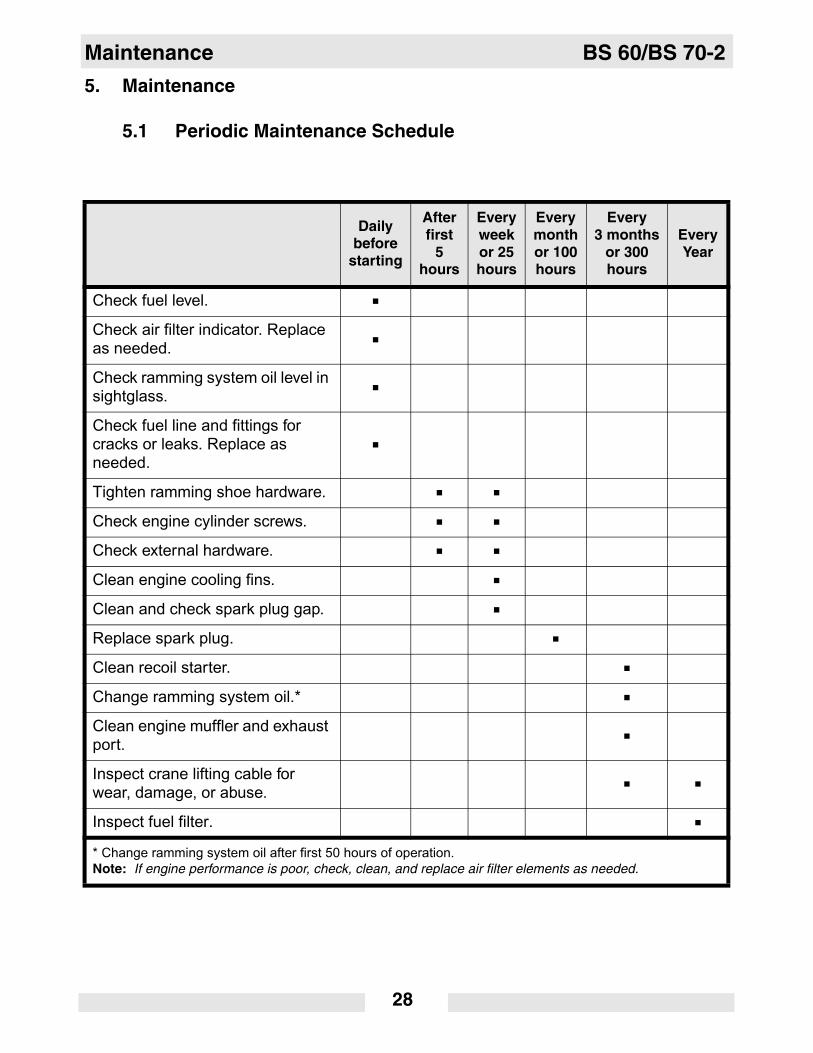
Maintenance BS 60/BS 70-2
5. Maintenance
5.1 Periodic Maintenance Schedule
Dailybefore
starting
Afterfirst
5hours
Everyweekor 25hours
Everymonthor 100hours
Every3 months
or 300hours
EveryYear
Check fuel level.
Check air filter indicator. Replace as needed.
Check ramming system oil level in sightglass.
Check fuel line and fittings for cracks or leaks. Replace as needed.
Tighten ramming shoe hardware.
Check engine cylinder screws.
Check external hardware.
Clean engine cooling fins.
Clean and check spark plug gap.
Replace spark plug.
Clean recoil starter.
Change ramming system oil.*
Clean engine muffler and exhaust port.
Inspect crane lifting cable for wear, damage, or abuse.
Inspect fuel filter.
* Change ramming system oil after first 50 hours of operation.Note: If engine performance is poor, check, clean, and replace air filter elements as needed.
28

BS 60/BS 70-2 Maintenance
5.2 Air CleanerSee Graphic: wc_gr001168
NEVER use gasoline or other types of low flash point solvents forcleaning the air filter. A fire or explosion could result.
NOTICE: NEVER run engine without main paper filter element (b).Severe engine damage will occur.
Filter Indicator
The air intake system is equipped with a filter indicator (h), whichindicates when a filter change is required. Replace the main paper filterelement (b) when the yellow plunger of the indicator appears in or nearthe red line. Push and hold in the yellow plunger on top of the indicatorto reset it after replacing the main paper filter element.
Clean elements using the following procedure:
5.2.1 Remove the air cleaner cover (a). Remove the main paper filterelement (b) and the secondary prefilter (c) and inspect them for holesor tears. Replace the elements if they are damaged.
5.2.2 Main paper filter element (b): Replace the main paper filter element ifit appears heavily soiled and/or when the yellow plunger of indicatorappears in or near the red line.
5.2.3 Prefilter (c): Clean it with low-pressure compressed air. When theprefilter is very soiled, wash it in a solution of mild detergent and warmwater. Rinse it thoroughly in clean water. Allow the prefilter to drythoroughly before reinstalling it.
Note: Do not oil the prefilter.
5.2.4 Wipe out the filter housing (d) with a clean cloth. Do not usecompressed air.
NOTICE: Do not allow dirt to get into the engine intake port (k) whilecleaning. Damage to engine will result.
5.2.5 Check that the precleaner debris ejector slot (i) is clear.
WARNING
wc_gr001168
a
b
c
d
k
i
h
29

Maintenance BS 60/BS 70-2
5.3 LubricationSee Graphic: wc_gr005326
Ramming system
Check oil level:
5.3.1 Tilt the machine backwards approximately 15° until the engine is levelby placing a wedge under the shoe.
5.3.2 Check the oil level through oil sightglass (d). Proper ramming systemlubrication is indicated when approximately 1/2–3/4 of the sightglass isfull.
5.3.3 If the oil is not visible, oil must be added through the sightglass port.Tilt rammer forward and remove sightglass (d). See Technical Datafor oil quantity and type.
5.3.4 Wrap the sightglass threads with teflon tape. Install the sightglass (d).Torque to 9 Nm.
5.3.5 Note: After transporting the rammer horizontally, upright the rammerand allow the oil to drain back through the engine. It may take up to 45minutes for the oil level to recover.
Oil change:
5.3.6 Unscrew the oil drain plug (e) located below the oil sightglass.
5.3.7 Tip the rammer back until it is resting on its handle and allow oil todrain.
Note: In the interests of environmental protection, place a plastic sheetand a container under the machine to collect any liquid which drainsoff. Dispose of this liquid in accordance with environmental protectionlegislation.
5.3.8 Screw in the oil drain plug (e). Torque to 54 Nm.
5.3.9 Remove sightglass (d) and fill with oil. See Technical Data for oilquantity and type. Wrap the sightglass threads with teflon tape. Installthe sightglass (d). Torque to 9 Nm.
30

BS 60/BS 70-2 Maintenance
wc_gr005326
31

Maintenance BS 60/BS 70-2
5.4 Fuel Lines
See Graphic: wc_gr005327
ALWAYS follow the instructions when disconnecting the fuel lines.Failure to do so may result in fuel leaking from the fuel system.
To disconnect the fuel lines:
5.4.1 Shut off the engine by moving the throttle through the detent to the offposition (a). The engine will stop and the fuel valve will close.
5.4.2 Open the fuel cap (b) to relieve normal operating pressure, and thenretighten it.
5.4.3 Remove the protective guard.
5.4.4 Pinch off both the fuel feed line (c) and the vent line (d) as close to thecarburetor as possible.
5.4.5 Carefully remove the fuel lines and drain the fuel left in the fuel linesinto an approved container.
Note: In the interests of environmental protection, place a plastic sheetand a container under the machine to collect any liquid which drainsoff. Dispose of this liquid in accordance with environmental protectionlegislation.
5.4.6 After service is complete, reconnect the lines to the proper fittings.Reconnect the fuel feed line (c) from the valve to the lower fitting andthe vent line (d) from the top of the tank to the upper fitting.
5.4.7 Replace the protective guard.
CAUTION
wc_gr005327
32

BS 60/BS 70-2 Maintenance
5.5 Shoe Hardware
See Graphic: wc_gr005384
On new machines, or after replacing shoe, check and tighten shoehardware after the first 5 hours of operation. Inspect hardware everyweek thereafter.
Torque hardware as specified.
Cast Iron Shoe Plastic Shoe
Torque Nm Ft.lbs.
T1 86 63
T4 17.6 13
T5 78.7 58
T1
T1
T5
T4
T4
T5
wc_gr005384
33

Maintenance BS 60/BS 70-2
5.6 Carburetor Adjustments
See Graphic: wc_gr004670
Refer to Technical Data for correct idle and operating rpm. For bestaccuracy, use a tachometer when making carburetor adjustments.
5.6.1 Start engine and allow it to warm up to operating temperature.
5.6.2 Set engine idle speed with engine running at idle and choke (a) fullyopen. Adjust idle speed screw (b), in or out, to obtain correct idlespeed.
NOTICE: DO NOT turn the adjusting screw in too tight or you maydamage the carburetor.
wc_gr004670
b
a
34

BS 60/BS 70-2 Maintenance
5.7 Storage
5.7.1 Drain the fuel from the tank.
5.7.2 Start the engine and run it until remaining fuel is used.
5.7.3 Remove the spark plug. Pour approximately 30 ml (1 oz.) of clean SAE10W30 engine oil into the cylinder through the spark plug opening.
5.7.4 Pull the starter rope slowly to distribute oil in the engine.
5.7.5 Re-install the spark plug.
5.8 Transportation
See Graphic: wc_gr005328
5.8.1 Always shut off the engine and close the fuel valve when transportingthe machine.
5.8.2 Make sure the lifting device has enough capacity to hold the machine(see identification plate on the machine for weight).
5.8.3 Use the central lifting point (a) when lifting the machine.
Always inspect the crane lifting cable for wear, damage, or abuse.Protect the cable from any sharp edges. Do not use the cable if thereare any signs of cut wires, excessive wear, or other defects. Replacethe damaged cable immediately to avoid injury or death.
5.8.4 Tie down the machine on the vehicle to prevent it from tipping, falling,or rolling. Lay the machine down flat and tie it to the vehicle at points(a) and (b).
NOTICE: Drain the fuel tank as required to prevent fuel leaking fromcap (c).
WARNING
wc gr005328
35

Maintenance BS 60/BS 70-2
5.9 Troubleshooting
Problem / Symptom Reason / Remedy
Engine does not start, or stalls.
• No fuel in tank.
• Spark plug fouled.
• Fuel valve closed.
Engine does not accelerate, is hard to start, or runs erratically.
• Improper fuel mix. Too much oil.
• Spark plug fouled.
• Clean muffler and exhaust port.
• Crankshaft seals are leaking.
• Check air cleaner.
Engine overheats. • Improper fuel mix. Not enough oil.
• Clean cooling fins and fan blades.
Engine runs, rammer does not tamp.
• Inspect clutch for damage. Replace if necessary.
• Broken connecting rod or crankgear.
• Low engine performance. Compression loss. Plugged exhaust port.
Engine runs, rammer operation is erratic.
• Oil/grease on clutch.
• Broken/worn springs.
• Soil buildup on ramming shoe.
• Broken parts in ramming system or crankcase.
• Engine operating speed is too high.
36

BS 60/BS 70-2 Technical Data
6. Technical Data
6.1 Rammer
Engine Power Rating
Net power rating per 80/1269/EEC and ISO 3046-1. Actual poweroutput may vary due to conditions of specific use.
Item Number:BS 60-2000941700094180009421
BS 70-20009424000942500094270620612
Rammer
Engine model type WM80
Engine speed - operating rpm 4400
Engine speed - idle rpm 1800 ± 100
Max. rated power @ rated speed
kW (Hp) 1.8 (2.4) @ 4400 rpm
Clutch engagement rpm 2500 ± 100
Spark plug type Champion RL95YC
Electrode gap mm (in) 0.5 (0.020)
Cylinder head compression (cold)
bar/cm3
(psi)8.0–9.7 (120–140)
Air cleaner type Three stage with cyclonic precleaner
Engine lubrication oil grade With standard two-cycle oil use 50:1 ratio.With Wacker Neuson two-cycle or other oil
meeting the NMMA TC-W3 specification, a ratiofrom 50:1 to 100:1 can be used.
Fuel tank capacity l (qts.) 3.0 (3.2)
Fuel consumption l(qt.)/hr 1.2 (1.3) 1.3 (1.4)
Running time hour 2.5 2.3
Ramming system lubrication
oil grade SAE 10W30
Ramming system capac-ity
ml (oz.) 890 (30)
37

Technical Data BS 60/BS 70-2
6.2 Sound Measurements
Products are tested for sound pressure level in accordance with ENISO 11204. Sound power level is tested in accordance with EuropeanDirective 2000/14/EC - Noise Emission in the Environment byEquipment for use outdoors.
• the sound pressure level at operator's location (LpA):
BS 60-2 = 96 dB(A)
BS 70-2 = 95 dB(A).
• the guaranteed sound power level (LWA) = 108 dB(A).
6.3 Vibration Measurements
Products are tested for hand/arm vibration (HAV) level in accordancewith ISO 5349, EN1033, and EN500-4 where applicable.
• HAV BS 60-2 = 7.6 m/s2
• HAV BS 70-2 = 6.8 m/s2
Refer to Section Proper Operation for further details.
38

BS 60/BS 70-2 Technical Data
6.4 Dimensions
mm (in.)
Machine Item Number Amm (in.)
Bmm (in.)
BS 60-2 000941700094180009421
280 (11.02)280 (11.02)280 (11.02)
336 (13.25)342 (13.45)336 (13.25)
BS 70-2 0009424000942500094270620612
280 (11.02)330 (12.99)280 (11.02)280 (11.02)
336 (13.25)342 (13.45)336 (13.25)336 (13.25)
wc_gr005329
343(13.5)
675(26.5)
B
965(38.0)
A
39


2008-CE-BS60-2-70-2-Q.fm
William Lahner Paul SinaVice President of Engineering Manager, Product Engineering
WACKER NEUSON CORPORATIONDate / Datum / Fecha / Date
EC DECLARATION OF CONFORMITYCE-KONFORMITÄTSERKLÄRUNG
DECLARACIÓN DE CONFORMIDAD DE LA CE DÉCLARATION DE CONFORMITÉ C.E.
WACKER NEUSON CORPORATION, N92 W15000 ANTHONY AVENUE, MENOMONEE FALLS, WISCONSIN USA
hereby certifies that the construction equipment specified hereunder / bescheinigt, daß das Baugerät / certifica que la máquina de construcción / atteste que le matériel :
1. Category / Art / Categoría / Catégorie Vibratory RammersVibrationsstampfer
Apisonadoras VibratoriasPilonneuses Vibrantes
2. Type - Typ - Tipo - Type BS 60-2, BS 60-2i, BS 70-2, BS 70-2i
3. Item number of equipment / Artikelnummer / Número de referencia de la máquina / Numéro de référence du matériel : 0009417, 0009418, 0009421, 0009419, 0009420,
0009424, 0009425, 0009427, 0009426, 0009428
4. Net installed power / absolute installierte Leistung / Potencia instalada neta / Puissance installée nette :BS 60-2, BS 60-2i 1,8 kW
BS 70-2, BS 70-2i 2,0 kWW
Has been sound tested per Directive 2000/14/EC / In Übereinstimmung mit Richtlinie 2000/14/EG bewertet worden ist / Ha sido ensayado en conformidad con la norma 2000/14/CE / A été mis à l’épreuve conforme aux dispositions de la directive 2000/14/CEE :
and has been produced in accordance with the following standards:und in Übereinstimmung mit folgenden Richtlinien hergestellt worden ist:y ha sido fabricado en conformidad con las siguientes normas:et a été produit conforme aux dispositions des directives européennes ci-après :
2000/14/EC2004/26/EC89/336/EEC98/37/EECEN 500-1EN 500-4
AUTHORIZED REPRESENTATIVE IN THE EUROPEAN UNIONBEVOLLMÄCHTIGTER VERTRETER FÜR DIE EUROPÄISCHE GEMEINSCHAFTREPRESENTANTE AUTORIZADO EN LA UNIÓN EUROPEAREPRÉSENTANT AGRÉÉ AUPRÈS DE L’UNION EUROPÉENNE
WACKER CONSTRUCTION EQUIPMENT AGPreußenstraße 4180809 München
Conformity Assessment Procedure / Konformitätsbewertungsverfahren / Procedimiento para ensayar conformidad / Procédé pour l’épreuve de conformité
Name and address of notified body / Bei folgender einbezogener Prüfstelle / Oficina matriculadora / Organisme agrée
Measured sound power level / Gemessener Schallleistungspegel / Nivel de potencia acústica determinado / Niveau de puissance acoustique fixé
Guaranteed sound power level / Garantierter Schallleistungspegel / Nivel de potencia acústica garantizado / Niveau de puissance acoustique garanti
Annex VIII / Anhang VIII Anexo VIII / Annexe VIII
BSI Product Services, Maylands Ave,
Hemel Hempstead,Herts, HP2 4SQ, UK.
BS 60-2, BS60-2i 106 dB(A)BS 70-2, BS70-2i 106 dB(A)
BS 60-2, BS60-2i 108 dB(A)BS 70-2, BS70-2i 108 dB(A)
15.07.08

Wacker Construction Equipment AG · Preußenstraße 41 · D-80809 München · Tel.: +49-(0)89-3 54 02 - 0 · Fax: +49 - (0)89-3 54 02-3 90Wacker Neuson Corporation · P.O. Box 9007 · Menomonee Falls, WI 53052-9007 · Tel. : (262) 255-0500 · Fax: (262) 255-0550 · Tel. : (800) 770-0957Wacker Asia Pacific Operations · Skyline Tower, Suite 2303, 23/F · 39 Wang Kwong Road, Kowloon Bay, Hong Kong · Tel. +852 2406 60 32 · Fax: +852 2406 60 21