b.sc. biochemistry ii cellular biochemistry unit 4 basic techniques in microbiology
TRANSCRIPT

Cellular BiochemistryUnit 4
Basic techniques in Microbiology
B.Sc Biochemistry II

Microscopy• What is microscopy?
• Why Microscope required?
• How to use microscope?
• Principle of microscope.
• Parts of Microscope.
• Types of microscope.
– Light microscope
• Bright field microscope
• The Dark-Field Microscope
• The Phase-Contrast Microscope
• The Fluorescence Microscope
– Scanning and electron microscope

Why Microscope,,,
1
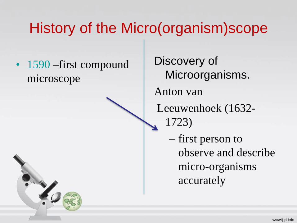
History of the Micro(organism)scope
• 1590 –first compound
microscope
Discovery of
Microorganisms.
Anton van
Leeuwenhoek (1632-
1723)
– first person to
observe and describe
micro-organisms
accurately

Microscope• Microscope is a tool
which can help you see
tiny objects and living
organisms. It makes
them look bigger.
• This ability of the
microscope is called its
magnifying power or
magnification.2
Microscope• The microscope also has the capacity to
distinguish small gaps between two
separate points which humans cannot
distinguish. It is called its resolving power
or resolution.

Light microscope
• Light microscope uses diffused light from
the sun or artificial light to illuminate the
object to be observed.

Types of Microscope
• Types of microscope.
Light microscopeBright field microscope
The Dark-Field Microscope
The Phase-Contrast Microscope
The Fluorescence Microscope
Electron microscopeScanning Electron microscope
Transmission Electron Microscope
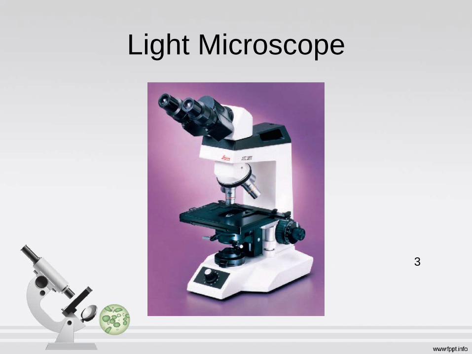
Light Microscope
3

Parts of Microscope
• Ocular (eyepiece)
• Body
• Arm
• Coarse focus
• adjustment knob
• Fine focus
• adjustment knob
• Stage adjustment
knobs
• Interpupillary
adjustment
• Nosepiece
• Objective lens (4)
• Mechanical stage
• Substage condenser
• Aperture diaphragm
control
• Base with light
source
• Field diaphragm
lever
• Light intensity
control

1.Arm
• Supports the body
tube.
4

2. Base
• Supports and
stabilizes the
microscope.
5

3. Eyepiece / ocular
lens
• Magnifies image
produced
by objective lens.
6

4. Body Tube
• Maintains the
proper distance
between the
objective and
ocular lenses.
7
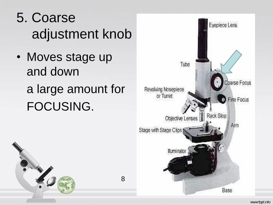
• Moves stage up
and down
a large amount for
FOCUSING.
5. Coarse
adjustment knob
8

• small, round knob on
the side of the
microscope used to
fine-tune the focus of
your specimen
• after using the coarse
adjustment knob
6. Fine adjustment
knob
8

7. Light source
• (lamp or mirror) Provides
light for viewing the slide.
• Projects light UPWARDS
through the diaphragm,
the SPECIMEN, and
the LENSES.
9

8. Diaphragm
• Controls the
amount of
light passing
through
the slide.
10

• Stage clips
- hold the slide in
place.
• Stage
- Supports the slide
being viewed.
9. Stage and stage
clips
11

Lens
Objective lens Condenser Lens
Usually you will find 3 or 4 objective lenses on
a microscope
It consist of 4X, 10X, 40X and 100X powers.
When coupled with a 10X (most common)
eyepiece lens, we get total magnifications of
40X (4X times 10X), 100X , 400X and 1000X
The purpose of the condenser lens is to focus
the light onto the specimen
Condenser lenses are most useful at the highest
powers (400X and above).
Microscopes with in stage condenser lenses
render a sharper image than those with no lens
(at 400X)
If the microscope has a maximum power of
400X, you will get the maximum benefit by
using a condenser lenses rated at 0.65 NA or
greater

10. Objective
lenses• Focus and magnify light
coming through the slide.
• Usually you will find 3 or 4
objective lenses on a
microscope. They almost
• always consist of 4X, 10X, 40X
and 100X powers. When
coupled with a 10X (most
common)
12

• eyepiece lens, we get total magnifications of 40X (4X
times 10X), 100X , 400X and 1000X. The shortest
• lens is the lowest power, the longest one is the lens with
the greatest power. Lenses are color coded.
• The high power objective lenses are retractable (i.e.
40XR). This means that if they hit a slide, the end of the
lens will push in (spring loaded) thereby protecting the
lens and the slide.
10. Objective lenses

High power objective lenses
Rotate so that the 100x oil immersion
objective touches the oil and clicks
into place.
13

Place a small drop of oil on
the slide in the center of the
lighted area. (Take care not to
dribble on the stage.)Put the
small drop of oil directly over
the area of the specimen to
be Examined.
High power objective lenses
14

Focus only with fine
focus. Hopefully, the
specimen will come
into focus easily. Do
not change focus
dramatically.
High power objective lenses

• Rotates to allow
use of
different power
objectives.
11. Revolving
nosepiece

• Supports the arm
and
controls the body
of the
microscope.
12. Inclination
joint

Bright Field microscope
• The ordinary microscope is called a bright-field microscope
because it forms a dark image against a brighter background. The
microscope consists of a sturdy metal body or stand composed of a
base and an arm to which the remaining parts are attached
• A light source, either a mirror or an electric illuminator, is
located in the base. Two focusing knobs, the fine and coarse
adjustment knobs, are located on the arm and can move either the
stage or the nosepiece to focus the image.

Microscope Vocabulary
• Magnification: increase of an object’s apparent size
• Resolution: The limit up to which two small objects are
still seen as separate entities is used as a measure of
the resolving power of a microscope. The distance
where this limit is reached is known as the effective
resolution of the microscope
• power to show details clearly
Both are needed to see a clear image

. 30
Lenses and the Bending of Light
• Light is refracted (bent) when passing from
one medium to another
• Refractive index
– a measure of how greatly a substance slows the
velocity of light , where c is the speed of light in vacuum and v is the speed of light in the substance
• Direction and magnitude of bending is
Determined by the refractive indexes of the
two media forming the interface

31
Focal point and Focal length
• Focus light rays at a specific place called the focal point
• Distance between center of lens and focal point is the focal length
• Strength of lens related to focal length
• short focal length more
magnification

32
Microscope Resolution
• Ability of a lens to separate or distinguish small objects that are close
together
• Wavelength of light used is major factor in resolution
shorter wavelength greater resolution
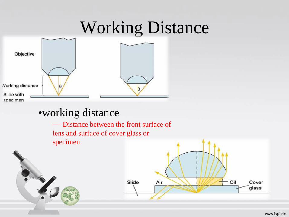
Working Distance
•working distance— Distance between the front surface of
lens and surface of cover glass or
specimen

Dark Field Microscope• Unstained cells and organisms can be observed
by simply changing the way in which they are
illuminated.
• A hollow cone of light is focused on the specimen
in such a way that unreflected and unrefracted
rays do not enter the objective.
• Only light that has been reflected or refracted by
the specimen forms an image.
• The field surrounding a specimen appears black,
while the object itself is brightly illuminated.
• Because the background is dark, this type of
microscopy is called dark-field microscopy.
Considerable internal structure is often visible
in larger eukaryotic microorganisms The dark-
field microscope is used to identify bacteria like
the thin and distinctively shaped Treponema
pallidum (figure 2.8a), the causative agent of
syphilis.

Phase-Contrast Microscope
• Unpigmented living cells are not clearly visible in
the brightfield microscope because there is little
difference in contrast between the cells and
water. Thus microorganisms often must be fixed
and stained before observation to increase
contrast and create variations in color between
cell structures.
• A phase-contrast microscope converts slight
differences in refractive index and cell density
into easily detected variations in light intensity
and is an excellent way to observe living cells.
• Phase-contrast microscopy is especially useful for
studying microbial motility, determining the shape
of living cells, and detecting bacterial components
such as endospores and inclusion bodies that
contain poly--hydroxybutyrate, olymetaphosphate,
sulfur, or other substances.15

Fluorescence Microscope• The microscopes thus far considered
produce an image from light that passes
through a specimen.
• An object also can be seen because it
actually emits light, and this is the basis of
fluorescence microscopy.
• When some molecules absorb radiant
energy, they become excited and later
release much of their trapped energy as
light.
• Any light emitted by an excited molecule
will have a longer wavelength (or be of
lower energy) than the radiation originally
absorbed.
• Fluorescent light is emitted very quickly
by the excited molecule as it gives up its
trapped energy and returns to a more
stable state.
16

Working of FM
• Fluorescence microscope exposes a specimen : ultraviolet, violet, or blue light
and forms an image of the object with the resulting fluorescent light.
• Mercury vapor arc lamp or other source produces an intense beam
• Heat transfer is limited by a special infrared filter.
• The light passes through an exciter filter that transmits only the desired wavelength.
A darkfield condenser provides a black background against which the fluorescent
objects glow.
• Usually the specimens have been stained with dye molecules, called
fluorochromes, that fluoresce brightly upon exposure to light of a specific
wavelength, but some microorganisms are auto fluorescing. The microscope forms
an image of the fluorochrome-labeled microorganisms
• A barrier filter positioned after the objective lenses removes any remaining
• ultraviolet light, which could damage the viewer’s eyes, or blue and violet light, which
would reduce the image’s contrast.
Applications of FM• The fluorescence microscope has become an essential tool is as follow:
• Medical microbiology and microbial ecology.
• Bacterial pathogens (e.g., Mycobacterium tuberculosis, the cause oftuberculosis) can be identified after staining them with fluorochromes orspecifically labeling them with fluorescent antibodies usingimmunofluorescence procedures.
• The stained organisms will fluoresce orange or green and can be detected evenin the midst of other particulate material. It is even possible to distinguishlive bacteria from dead bacteria by the color they fluoresce aftertreatment with a special mixture of stains
• Thus the microorganisms can be viewed and directly counted in arelatively undisturbed ecological niche.

Basic Microscope Technique
Rules to Follow1. If you must carry a microscope, always hold it with one hand
on the arm and the other under the base.
2. Always lower the stage or raise the objectives all the way before placing a slide under the objectives.
3. Always begin working with the LOW POWER (shortest) objective first.
4. Observe the slide from the side, not looking through the eye piece, when using the coarse focus to avoid running the objective lens into the slide.
5. Never use the coarse focus adjustment when on the medium or high power objectives. Focus on low power first and then rotate the higher power objective into place. Make final focus adjustments with the fine focus adjustment.

Electron microscope• Size of object: about 0.2 micro meter
• Object examine: viruses or the internal structures of cells
• Sources : Electrons is used instead of light.
• Resolving power: Greater than that of the other microscopes
• Images: Black and white, but they may be colored artificially to accentuate
certain details.
• Glasses: Electromagnetic lenses to focu s a beam of electrons onto a
specimen.
• Types of electron microscopes: Transmission electron microscope and
the scanning electron microscope.

Transmission Electron Microscope
• Limitation of light microscope: resolution limit of about 0.2
micrometer. The bacteria usually are around 1 micrometer in
diameter,
• General shape and major morphological features are visible in
the light microscope.
• The detailed internal structure of larger microorganisms also
cannot be effectively studied by light microscopy.
• These limitations arise from the nature of visible light waves, not
from any inadequacy of the light microscope itself.
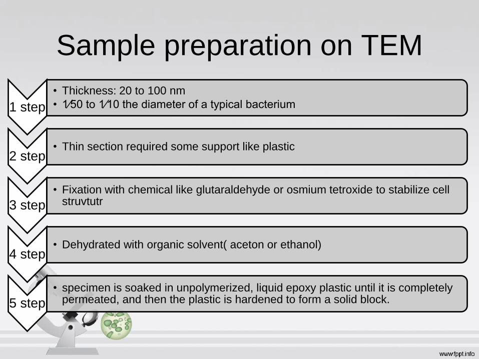
Sample preparation on TEM
1 step
• Thickness: 20 to 100 nm
• 1⁄50 to 1⁄10 the diameter of a typical bacterium
2 step• Thin section required some support like plastic
3 step
• Fixation with chemical like glutaraldehyde or osmium tetroxide to stabilize cell struvtutr
4 step• Dehydrated with organic solvent( aceton or ethanol)
5 step
• specimen is soaked in unpolymerized, liquid epoxy plastic until it is completely permeated, and then the plastic is hardened to form a solid block.

6 step
• Thin sections are cut from this block with a glass or diamond knife using a special instrument called an ultramicrotome.
7 step
• Cells usually must be stained before they can be seen clearly in the bright-field microscope;
8 step
• prepared for observation by soaking thin sections with solutions of heavy metal salts like lead citrate and uranyl acetate.
9 step
• The lead and uranium ions bind to cell structures and make them more electron opaque, thus increasing contrast in the material. Heavy osmium atoms from the osmium tetroxidefixative also “stain” cells and increase theircontrast.
9 step
• The lead and uranium ions bind to cell structures and make them more electron opaque, thus increasing contrast in the material. Heavy osmium atoms from the osmium tetroxide fixative also “stain” cells and increase their contrast.
10 step• The stained thin sections are then mounted on tiny copper grids and viewed

Working of TEM• Tungsten filament: generates a beam of
electrons that is then focused on the
specimen by the condenser
• Magnetic lenses: are used to focus the
beam
• The column containing the lenses and
specimen must be under high vacuum to
obtain a clear image because electrons
are deflected by collisions with air
molecules.
• Magnetic lenses : Form the Enlarged,
visible image of the specimen on a
fluorescent screen.
• Photographic film: The screen can also
be moved aside and the image captured
on photographic film as a permanent
record.
17

Characteristics of TEM and LM

Scanning microscope
• Specification of SM:
• Examine the surfaces of microorganisms
• Principle: “The SEM differs from other electron microscopes in
producing an image from electrons emitted by an object’s surface
rather than from transmitted electrons”.
• Specimen preparation is easy,
• Air-dried material can be examined directly.

Method and sample preparation
1 step• Fixation
2 step• Dehydrated the cell
3 step• Dried to preserve surface structure and prevent collapse of the cells when they are exposed to the SEM’s high vacuum.
4 step
• Before viewing, dried samples are mounted and coated with a thin layer of metal to prevent the buildup of an electrical charge on the surface and to give a better image.
5 step
• specimen is soaked in unpolymerized, liquid epoxy plastic until it is completely permeated, and then the plastic is hardened to form a solid block.
6 step• The SEM scans a narrow, tapered electron beam back and forth over the specimen
7 step• When the beam strikes a particular area, surface atoms discharge a tiny shower of electrons called secondary electrons.
8 step• trapped by a special detector.
9 step
• Secondary electrons entering the detector strike a scintillator causing it to emit light flashes that a photomultiplier converts to an electrical current and amplifies.

What is SEM?
It is a microscope that produces an image by using
an electron beam that scans the surface of a
specimen inside a vacuum chamber.
The SEM is designed for direct studying of the surfaces
of solid objects.
Scanning electron microscope (SEM) is a microscope
that uses electrons rather than light to form an image.
There are many advantages to using the SEM instead of a
OM.

Scanning Electron Microscope– a Totally Different Imaging Concept
Instead of using the full-field image, a point-to-
point measurement strategy is used.
High energy electron beam is used to excite the
specimen and the signals are collected and
analyzed so that an image can be constructed.
The signals carry topological, chemical and
crystallographic information, respectively, of the
samples surface.

HOW THE SEM WORKS?
The SEM uses electrons instead of light to form an
image.
A beam of electrons is produced at the top of the
microscope by heating of a metallic filament.
The electron beam follows a vertical path through
the column of the microscope. It makes its way through
electromagnetic lenses which focus and direct the
beam down towards the sample.
Once it hits the sample, other electrons
( backscattered or secondary ) are ejected from the
sample. Detectors collect the secondary or
backscattered electrons, and convert them to a signal
that is sent to a viewing screen similar to the one in an
ordinary television or computer.
18
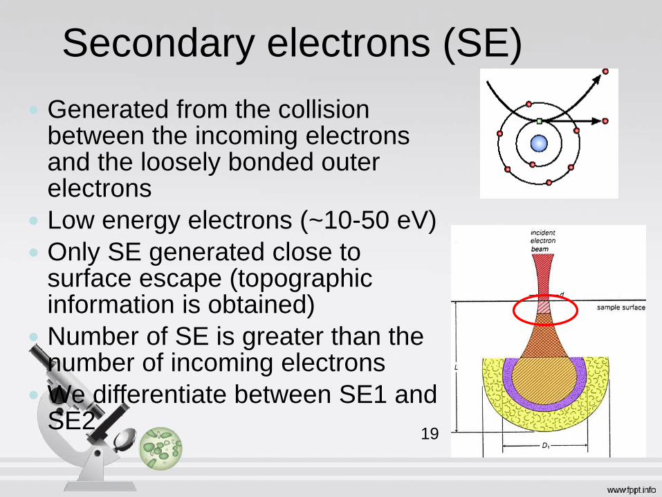
Secondary electrons (SE)
Generated from the collision between the incoming electrons and the loosely bonded outer electrons
Low energy electrons (~10-50 eV)
Only SE generated close to surface escape (topographic information is obtained)
Number of SE is greater than the number of incoming electrons
We differentiate between SE1 and SE2
19

SE1 The secondary electrons that are generated by the
incoming electron beam as they enter the surface
High resolution signal with a resolution which is only
limited by the electron beam diameter
SE2
The secondary electrons that are
generated by the backscattered
electrons that have returned to the
surface after several inelastic
scattering events
SE2 come from a surface area that
is bigger than the spot from the
incoming electrons resolution is
poorer than for SE1 exclusively
Sample
surface
Incoming electronsSE2

Backscattered electrons (BSE)
A fraction of the incident electrons is
retarded by the electro-magnetic field of
the nucleus and if the scattering angle
is greater than 180° the electron can
escape from the surface
High energy electrons (elastic
scattering)
Fewer BSE than SE
We differentiate between BSE1 and
BSE2

How do we get an image?
Image
Detector
Electron gun

Signals from the sample
Incoming electrons
Secondary electrons
Backscattered
electrons
Auger electrons
X-rays
Cathod-
luminescence (light)
Sample

How an Electron Beam is Produced?
Electron guns are used to produce a fine, controlled beam of electrons which are then focused at the specimen surface.
The electron guns may either be
thermionic gun or field-emission gun

Some comments on resolution
Best resolution that can be obtained: size of the electron spot on the sample surface The introduction of FEG has dramatically improved the
resolution of SEM’s
The volume from which the signal electrons are formed defines the resolution SE image has higher resolution than a BSE image
Scanning speed: a weak signal requires slow speed to improve signal-to-
noise ratio
when doing a slow scan drift in the electron beam can affect the accuracy of the analysis

Why Black and white image?
• The number of secondary electrons reaching the detector depends on the nature of
the specimen’s surface. When the electron beam strikes a raised area, a large
number of secondary electrons enter the detector.
• In contrast, fewer electrons escape a depression in the surface and reach the
detector.
• Thus raised areas appear lighter on the screen and depressions are darker.
• A realistic three-dimensional image of the microorganism’s surface with great depth
of focus results.
• The actual in situ location of microorganisms in ecological niches such as the human
skin and the lining of the gut also can be examined

Application of SEM
• Human skin and the lining of the gut also
can be examined.

Flowcytometry
Sorting the Cells
60

Intro
• Flow cytometry is a laser-based, biophysical technology employed majorly in cell counting and cell sorting.
• By suspending cells in a stream of fluid and passing them by an electronic detection apparatus;
• It allows simultaneous multiparametricanalysis of the physical and chemical characteristics of up to thousands of particles per second.
61
• A flow cytometer is similar to
a microscope, except that, instead of
producing an image of the cell, flow
cytometry offers "high-throughput" (for a
large number of cells)
automated quantification of set
parameters.
• For analysis, a single-cell suspension
must first be prepared.62

History• The first impedance-based flow cytometry device,
using the Coulter principle, US patent 1953, by Wallace H. Coulter.
• The Coulter Counter is a vital constituent of today's hospital laboratory.
• Its primary function being the quick and accurate analysis of complete blood counts (often referred to as CBC). The CBC is used to determine the number or proportion of white and red blood cells in the body.
• Previously, this procedure involved preparing a blood cell stain and manually counting each type of cell under a microscope.
63
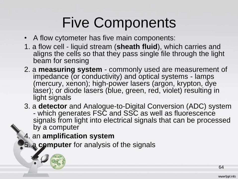
Five Components• A flow cytometer has five main components:
1. a flow cell - liquid stream (sheath fluid), which carries and aligns the cells so that they pass single file through the light beam for sensing
2. a measuring system - commonly used are measurement of impedance (or conductivity) and optical systems - lamps (mercury, xenon); high-power lasers (argon, krypton, dye laser); or diode lasers (blue, green, red, violet) resulting in light signals
3. a detector and Analogue-to-Digital Conversion (ADC) system - which generates FSC and SSC as well as fluorescence signals from light into electrical signals that can be processed by a computer
4. an amplification system
5. a computer for analysis of the signals
64

Fluorescence-activated cell sorting
(FACS)
• FACS is a specialized type of flow cytometry
• It provides a method for sorting a heterogeneous mixture of biological cells into two or more containers, one cell at a time, based upon the specific light scattering and fluorescent characteristics of each cell.
• It is a useful scientific instrument as it provides fast, objective and quantitative recording of fluorescent signals from individual cells.
• Physical separation of cells of particular interest.
65

66
19

• The cell suspension is entrained in the center
of a narrow, rapidly flowing stream of liquid.
• A vibrating mechanism causes the stream of
cells to break into individual droplets.
• The system is adjusted so that there is a low
probability of more than one cell per droplet.
• The flow passes through a fluorescence
measuring station where the fluorescent
character of interest of each cell is measured.
67

• The charge is then provided by an
electrical charging ring based on the
immediately prior fluorescence intensity
measurement as it breaks from the
stream.
• The charged droplets then fall through an
electrostatic deflection system that diverts
droplets into containers based upon their
charge.68

69
20

Applications
• The technology has applications in a number of fields, including medicine, molecular biology, pathology, immunology, plant biology and marine biology.
• Flow cytometry is routinely used in the diagnosis of health disorders, especially blood cancers, but has many other applications in basic research, clinical practice and clinical trials.
• A common variation is to physically sort particles based on their properties, so as to purify populations of interest.
70

Measurable parametersThis list is very long and constantly expanding,
• used for confirming diagnosis of chronic lymphocytic leukemia
• volume and morphological complexity of cells
• cell pigments such as chlorophyll or phycoerythrin
• total DNA content (cell cycle analysis, cell kinetics, proliferation, ploidy, aneuploidy, endoreduplication, etc.)
• total RNA content
• DNA copy number variation (by Flow-FISH or BACs-on-Beads technology)
• chromosome analysis and sorting (library construction, chromosome paint)
• protein expression and localization
71

• Protein modifications, phospho-proteins
• transgenic products in vivo, particularly the Green fluorescent protein or
related Fluorescent Proteins
• cell surface antigens (Cluster of differentiation (CD) markers)
• intracellular antigens (various cytokines, secondary mediators, etc.)
• nuclear antigens
• enzymatic activity
• pH, intracellular ionized calcium, magnesium, membrane potential
• membrane fluidity
• apoptosis (quantification, measurement of DNA degradation, mitochondrial
membrane potential, permeability changes, caspase activity)
• cell viability
• monitoring electropermeabilization of cells
• characterising multidrug resistance (MDR) in cancer cells
• cell adherence (for instance pathogen-host cell adherence)
References • Images references:
1. https://www.gotoknow.org/posts/105470
2. http://polaros.com/fulminant-community-acquired-acinetobacter-baumannii-pneumonia-as-a-
distinct-clinical-syndrome-definition-of-terms.html
3. http://classroom.sdmesa.edu/eschmid/Lecture2-Microbio.htm
4-12. http://www.microscope-microscope.org/basic/microscope-parts.htm
13. https://lh5.ggpht.com/cpmDJKCYbRS3m-
1aZ4sebX0N8CVLomv91vEWuz3o1fgDbta2PRzWdypNFK_PepEUDh2d=s94
14.https://lh3.ggpht.com/_o1NDOt21DJ6iRN_HXPvlD33VgW9TgI4R8S1h8ZM5SJV6zTEymBszraZ8
Uw9WaJc_uZx_g=s85
15.https://lh3.ggpht.com/_o1NDOt21DJ6iRN_HXPvlD33VgW9TgI4R8S1h8ZM5SJV6zTEymBszraZ8
Uw9WaJc_uZx_g=s85
16.https://lh4.ggpht.com/rkbrNOAx19H0eYFDzacAQDb4uJJ3Iir6EdnOPFJaV_tt0XwCM6F658klSf9C
G8VOwZFd=s85
17.https://lh4.ggpht.com/H139WLhETH5qmKCJN4klUnXKqK8JRO1mmxSquqPXiXYIK1OVlucstd_
NjC7hsJ7zPbaoQw=s85
18.https://lh3.ggpht.com/x9ZN7zdwK4DtGWVV1_3d2Whjp2BQG8iaHAsMWOZ9mePvXsj3zUhS5k6
0LblAlbJ4Nz4qBA=s85
19. https://lh5.ggpht.com/2QC5nq87J8qpEdrdn6XJa-
H5jpDMSY7Z2JxU6JruwVIeAbP64DvFYGiiauwYnlkXd4HgxS8=s108
20. http://en.wikipedia.org/wiki/Flow_cytometry

• Reading references:
• Cell and Molecular Biology, 6th Ed By Karp
• Molecular Cell Biology by Lodish 5th Edition