b.tech (eee iv sem) - dbit.ac.in · microprocessor & its application ... classification...
TRANSCRIPT

2018
Department of Electrical & Electronics Engineering
Student’s Handbook |
B.Tech (EEE IV Sem)
Subject Faculties
EMEC- II & Lab
Elements of Power System
Electrical & Electronics Engineering
Microprocessor & its Application
Communication Engineering
Signal & Systems
Communication Engineering Lab
18

Student’s Handbook | B.Tech (EEE IV Sem) 2018
FOREWORD
Dear Student,
We, at DBGI, are committed to facilitate all aspiring students in their selection of different streams of B.Tech. by putting our efforts in terms of commitment, providing the services of quality and skill oriented education.
The exponential expansion in the field of technology has offered a plethora of job opportunities in emerging sectors. It has also resulted in innumerable demand for qualified “skilled” manpower in these sectors.
At this crossroads of your life where a wrong turn can take you miles away from your goal. Choosing your career path is an important step because your future is at stake. It is generally
observed that a large section of students are unaware of what they want to achieve in their life.
This amounts to a situation like boarding a train without knowing one’s destination. Undoubtedly it may result in waste of precious time and money.
Student Handbook is purposely designed for the students. We have been planning for some time to provide collective information about academics as well as Institute to our new comers.
It comprises complete information of syllabi of all subjects, Lecture Plans, assignments, question bank, tutorials, marking scheme etc. However in addition to this, if students have any
problem or query they can contact Student Information Cell.
We are living in a competitive world; the key to edging out of competition is information and preparation. We hope that this booklet gives you enough leverage to understand about the institute and academics.
Success to a large extent depends on your attitude which includes your sincerity and strong
will to vigorously pursue your goal. It’s your determination to fulfill the requirements that are needed to enable you achieve your goal. It means you have to acquire the required academic
qualification and skills followed by professional qualification and training in your particular field. Once you have these, you will be able to compete.
With Best Wishes
Mr. Rohit Dobriyal (H.O.D) Department of Electrical & Electronics Engg.
Dev Bhoomi Group of Institutions
Department of Electrical & Electronics Engineering

Student’s Handbook | B.Tech (EEE IV Sem) 2018
CONTENTS
1 Evaluation Scheme
2 Syllabus 2.1 EMEC- II
2.2 Elements of Power System
2.3 Electrical & Electronics Engineering
2.4 Microprocessor & its Application
2.5 Communication Engineering 2.6 Signal & Systems 2.7 EMEC- II Lab
2.8 Microprocessor Lab
2.9 Communication Engineering Lab
2.10 General Proficiency
3 Lesson Plan 3.1 EMEC- II
3.2 Elements of Power System
3.3 Electrical & Electronics Engineering 3.4 Microprocessor & its Application
3.5 Communication Engineering
3.6 Signal & Systems
4 Assignments 4.1 EMEC- II
4.2 Elements of Power System
4.3 Electrical & Electronics Engineering
4.4 Microprocessor & its Application
4.5 Communication Engineering 4.6 Signal & Systems
5 Tutorial Sheets 5.1 EMEC- II
5.2 Elements of Power System
5.3 Electrical & Electronics Engineering
5.4 Microprocessor & its Application
5.5 Communication Engineering
5.6 Signal & Systems
6 Question Bank 6.1 EMEC- II
6.2 Elements of Power System
6.3 Electrical & Electronics Engineering 6.4 Microprocessor & its Application
6.5 Communication Engineering
6.6 Signal & Systems
Department of Electrical & Electronics Engineering

Student’s Handbook | B.Tech (EEE IV Sem) 2018
1 Evaluation Scheme
Department of Electrical & Electronics Engineering

Prerequisite: Knowledge of Basic Electronics
UNIT – I : (7L)
Bonds in solids, crystal structure, co-ordination number, atomic radius representation of plane distance b/w
two planed packing factor, Miller Indices, Bragg’s law and x-ray diffraction, structural Imperfections,
crystal growth
UNIT – II : (7L)
Polarization and Dielectric constant, Dielectric constant of mono-atomic, Poly atomic gases and solids,
frequency dependence of electronic and ionic polarisabilities, dipolar relaxation, dielectric loss,
piezoelectricity, ferroelectric materials
UNIT – III : (8L) Electron theory of metals, factors affecting electrical resistance of materials, thermal conductivity of metals, heat developed in current carrying conductors, Half effect, Drift and Diffusion
currents, continuity equation, thermoelectric effect, superconductivity and super conducting materials,
optical properties of solids
UNIT – IV : (8L)
Origin of permanent magnetic dipoles in matters, Classification Diamagnetism, Paramagnetism, Ferromagnetism, Antiferromagnetism and Ferrimagnetism, magnetostriction, Properties of magnetic
materials, soft and hard magnetic materials, permanent magnetic materials.
References : 1 Solymar, “Electrical Properties of Materials” Oxford University Press. 2. Ian P. Hones,” Material Science for Electrical and Electronic Engineering,” Oxford
University Press. 3 A.J. Dekker,”Electrical Engineering Materials” Prentice Hall of India
Course Outcome Description
CO1 To learn about various types of materials and there use in electrical & electronics
application.
CO2 To get an insight of the structure of various engg. Materials
CO3 To understand and visualize the theory of electrons and how they are affected by
different conditions to show their different properties.
CO4 T o understand about the magnetic properties of an element and different aspects of
the same.
Dev Bhoomi Institute Of Technology
SEMESTER: IV
Department of Electrical & Electronics Engineering
Course Level: Beginner Course Type:
Core
Credit: 4
Total Contact Hours: 30 LTP -2-1-0 External Marks/Internal Marks:
50/50
Course Title: ELECTRICAL &
ELECTRONICS ENGINEERING MATERIALS
Course Code: TEE403 Duration of External Exam: 2
Hours

Prerequisite: Knowledge of Digital Electronics & Design Aspect
UNIT-I: (7L)
Introduction to Microprocessors: Evolution of Microprocessors, history of computers, Timing and
control , Memory devices: Semiconductor memory organization, Category of memory
UNIT-II: (6L) 8-bit Microprocessors (8085): Architecture, Instruction Set, Addressing modes, Assembly Language
Programming
UNIT-III: ( 9 L ) 16-bit Microprocessors (8086): Architecture, Physical address, segmentation, memory
organization, Bus cycle, Instruction Set, Addressing modes, difference between 8085 & 8086 ,
Assembler Directives , Assembly Language Programming of 8086
UNIT-IV: (9L) Peripheral Interfacing: Introduction, Types of transmission, 8257 (DMA), 8255 (PPI), Serial Data
transfer (8251), Keyboard-display controller (8279), Programmable Priority Controller (8259), 8253,
ADC, Application of peripheral devices
UNIT-V: (9L) Advanced Microprocessors: Introduction to 80186, 80286, 80386, 80486, Pentium microprocessors,
introduction To Microcontroller (8051) Reference Books: 1 Gaonkar, Ramesh S, “Microprocessor Architecture, programming and applications with the 8085” Pen ram International Publishing 5th Ed. 2 Ray, A.K. & Burchandi, K.M., “Advanced Microprocessors and eripherals: Architecture, Programaming and Interfacing” Tata Mc. Graw Hill
Dev Bhoomi Institute Of Technology
SEMESTER: IV
Department of Electrical & Electronics Engineering
Course Level: Beginner Course Type:
Core
Credit: 4
Total Contact Hours: 40 LTP -3-1-0 External Marks/Internal Marks:
100/50
Course Title:
MICROPROCESSOR
Course Code: TEE404 Duration of External Exam: 3
Hours
Course Outcome Description
CO1 Knowledge of architecture of basic microprocessors .
CO2 Ability to build a microprocessor based system for practical applications
CO3 To learn the working of 16 bit microprocessor 8086 and it’s assembly language.
CO4 To understand the concept of peripheral interfacing among various devices.
CO5 Understand the advance version of microprocessors and introduction of
microcontrollers.
Prerequisite: Knowledge of Basic Electrical Unit I: (10L) Constructional features, Armature winding, EMF Equation, Winding coefficients, equivalent circuit and phasor diagram, Armature reaction, O. C. & S. C. tests, Voltage Regulation using Synchronous Impedance Method, MMF Method, Potier’s Triangle Method, Parallel Operation of synchronous generators, operation on infinite bus, synchronizing power and torque co-efficient
Unit II : (8L) Two Reaction Theory, Power flow equations of cylindrical and salient pole machines, Operating characteristics ,Synchronous Motor: Starting methods, Effect of varying field current at different loads, V Curves, Hunting & damping, synchronous condensor
Unit III : (8L) Constructional features, Rotating magnetic field, Principle of operation phasor diagram, equivalent circuit,
torque and power equations, Torque- slip characteristics, no load & blocked rotor tests, efficiency,
Induction generator
Unit IV : (8L) Starting, Deep bar and double cage rotors, Cogging & Crawling, Speed Control (with and without emf
injection in rotor circuit.)
Single phase Induction Motor
Double revolving field theory, Equivalent circuit, No load and blocked rotor tests, Starting methods, repulsion motor.AC Commutator Motors:
Unit V (6) Universal motor, Single phase a.c. series compensated motor, stepper motors Reference Books:
1. El Hawary, “Principles of Electrical Machines with Power Electronics”, Wiley India 2. D.P.Kothari & I.J.Nagrath, “Electric Machines”, Tata Mc Graw Hill
Course Outcome Description
CO1 Get exposed to various types of electrical machines and learn constructional
details principle of operation of synchronous machines.
CO2 Explain the working principle of dual winding squirrel cage induction generator
and Describe the phenomenon of cogging and crawling in induction motors.
CO3 Explain the working principle of doubly fed induction generator with sketches.
CO4 Explain the working principle of different types of stepper motors, Brushless DC
Motor and their applications and universal motor
CO5 To understand the concept of different motors with special properties.
Dev Bhoomi Institute Of Technology
SEMESTER: IV
Department of Electrical & Electronics Engineering
Course Level: Beginner Course Type:
Core
Credit: 4
Total Contact Hours: 40 LTP -3-1-0 External Marks/Internal Marks:
100/50
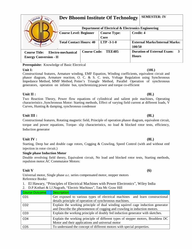
Course Title: Electro-mechanical
Energy Conversion - II Course Code: TEE405 Duration of External Exam: 3
Hours

Prerequisite: Knowledge of Basic Electrical
Unit 1: (10L)
Single line Diagram of Power system, Brief description of power system Elements: Synchronous
machine, transformer, transmission line, bus bar , circuit breaker and isolator.
Supply System
Different kinds of supply system and their comparison, choice of transmission voltage Transmission Lines: Configurations, types of conductors, resistance of line, skin effect, Kelvin’s law. Proximity effect
Unit 2 : (10L)
Calculation of inductance and capacitance of single phase, three phase, single circuit and double circuit transmission lines, Representation and performance of short, medium and long transmission lines, Ferranti effect. Surge impedance loading
Unit 3 : (7L)
Phenomenon of corona, corona formation, calculation of potential gradient, corona loss, factors affecting corona, methods of reducing corona and interference. Electrostatic and electromagnetic interference with communication lines,
Overhead line Insulators:
Type of insulators and their applications, potential distribution over a string of insulators,
methods of equalizing the potential, string efficiency.
Unit 4 : (7L)
Catenary curve, calculation of sag & tension, effects of wind and ice loading, sag template, vibration dampers.
Unit 5 : (6L)
Type of cables and their construction, dielectric stress, grading of cables, insulation resistance,
capacitance of single phase and three phase cables, dielectric loss, heating of cables.
Reference Books
1. Weedy, “Electric Power Systems”, Wiley India 2. P.S.R.Murthi, Electrical Power System. B.S. Publications
3. W. D. Stevenson, “Element of Power System Analysis”, McGraw Hill, USA
Dev Bhoomi Institute Of Technology
SEMESTER: IV
Department of Electrical & Electronics Engineering
Course Level: Beginner Course Type:
Core
Credit: 4
Total Contact Hours: 40 LTP -3-1-0 External Marks/Internal Marks:
100/50
Course Title: Element of
Power System
Course Code: TEE406 Duration of External Exam: 3
Hours
Course Outcome Description
CO1 Design of closed loop system which is used in industry by frequency response
method
CO2 Understand the concepts of economic power generation and different power
system element, substation
CO3 To determine the inductance and capacitance of all the phases & performance of
different transmission line
CO4 Analyze the corona effect produce in the overhead transmission line & line
interference
CO5 To analyze of sag & tension the and effect produce by wind and ice loading on
overhead transmission line
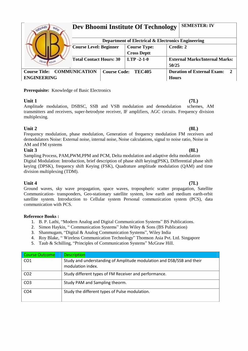
Prerequisite: Knowledge of Basic Electronics
Unit 1 (7L) Amplitude modulation, DSBSC, SSB and VSB modulation and demodulation schemes, AM
transmitters and receivers, super-hetrodyne receiver, IF amplifiers, AGC circuits. Frequency division
multiplexing.
Unit 2 (8L) Frequency modulation, phase modulation, Generation of frequency modulation FM receivers and
demodulators Noise: External noise, internal noise, Noise calculations, signal to noise ratio, Noise in AM and FM systems
Unit 3 (8L) Sampling Process, PAM,PWM,PPM and PCM, Delta modulation and adaptive delta modulation Digital Modulation: Introduction, brief description of phase shift keying(PSK), Differential phase shift
keying (DPSK), frequency shift Keying (FSK), Quadrature amplitude modulation (QAM) and time
division multiplexing (TDM).
Unit 4 (7L) Ground waves, sky wave propagation, space waves, tropospheric scatter propagation, Satellite
Communication- transponders, Geo-stationary satellite system, low earth and medium earth-orbit
satellite system. Introduction to Cellular system Personal communication system (PCS), data
communication with PCS.
Reference Books :
1. B. P. Lathi, “Modern Analog and Digital Communication Systems” BS Publications. 2. Simon Haykin, “ Communication Systems” John Wiley & Sons (BS Publication) 3. Shanmugam, “Digital & Analog Communication Systems”, Wiley India 4. Roy Blake, “ Wireless Communication Technology” Thomson Asia Pvt. Ltd. Singapore 5. Taub & Schilling, “Principles of Communication Systems” McGraw Hill.
Dev Bhoomi Institute Of Technology
SEMESTER: IV
Department of Electrical & Electronics Engineering
Course Level: Beginner Course Type:
Cross Deptt
Credit: 2
Total Contact Hours: 30 LTP -2-1-0 External Marks/Internal Marks:
50/25
Course Title: COMMUNICATION
ENGINEERING
Course Code: TEC405 Duration of External Exam: 2
Hours
Course Outcome Description
CO1 Study and understanding of Amplitude modulation and DSB/SSB and their modulation index.
CO2 Study different types of FM Receiver and performance.
CO3 Study PAM and Sampling theorm.
CO4 Study the different types of Pulse modulation.

Prerequisite: Knowledge of Basic Electrical & Mathematics
Unit-I Signals and Systems: (L8)
Continuous-time and discrete-time Signals, Transformations of the Independent Variable, Exponential and
Sinusoidal Signals, Continuous-Time and Discrete-Time LTI Systems and their properties, convolution
sum and convolution integrals, LTI System described by differential and difference equation.
Unit-II Fourier series and Fourier Transformer (L10)
The response of LTI Systems to Complex Exponentials, Fourier Series Representation of Continuous-time Periodic Signals and their Properties, Continuous time and discrete time Fourier Transforms and their properties, System Characterized by Linear Constant Coefficient Differential equations and Difference equation.
Unit-III Time and Frequency Characterization of Signals and Systems (L6)
Magnitude Phase Representation of the Fourier Transform, Magnitude Phase Representation of the Frequency response of LTI systems, Time domain Properties of Ideal Frequency Selective filter, Time Domain and Frequency Domain aspects of Non ideal filters, First Order and Second Order Continuous Time and Discrete time Systems.
Unit-IV Sampling and Laplace Transform (L8)
Signal representation by samples, sampling theorem, Impulse train sampling, sampling of discrete time signals, discrete time processing of continuous time signals. Laplace Transform, Region of convergence, inverse Laplace Transform,Analysis and characterization of LTI System, Block diagram representation, Unilateral Laplace transform.
Unit-V (L8)
Z-Transform, Region of convergence, Inverse Ztransform,analysis and characterization of LTI
system, Block diagram representation, Unilateral Z-transform.
Refrences:
1. Haykin, “Signals & Systems”, Wiley India
2 .BPLathi,Signals&Systems,BSPublication,Hyd.
Dev Bhoomi Institute Of Technology
SEMESTER: IV
Department of Electrical & Electronics Engineering
Course Level: Beginner Course Type:
Cross Deptt
Credit: 4
Total Contact Hours: 40 LTP -3-1-0 External Marks/Internal Marks:
100/50
Course Title: SIGNAL &
SYSTEM
Course Code: TEC402 Duration of External Exam: 3
Hours
Course Outcome Description
CO1 Analyze various processing steps involved in IC Fabrication and explain the fabrication process of any monolithic devices
CO2 Understand the Photo lithography and It’s types in the IC fabrication Process.
CO3 Learn about Ion Implantation, Diffusion and oxidation in the fabrication process.
CO4 Metallization in the Fabrication process of the MOSFET.
CO5 Understand the Epitexy, Eaching process in the fabrication process.

The minimum 8 experiments are to be performed from the following,
out of which there should be at least two software based experiments.
1. To perform no load and blocked rotor tests on a three phase squirrel cage induction motor and
determine equivalent circuit.
2. To perform load test on a three phase induction motor and draw:
(i) Torque -speed characteristics
(ii) Power factor-line current characteristics
3. To perform no load and blocked rotor tests on a single phase induction motor and determine
equivalent circuit.
4. To study speed control of three phase induction motor by
Keeping V/f ratio constant
5. To study speed control of three phase induction motor by varying supply voltage.
6. To perform open circuit and short circuit tests on a three phase alternator and determine
voltage regulation at full load and at unity, 0.8 lagging and leading power factors by (i) EMF
method (ii) MMF method.
7. To determine V-curves and inverted V-curves of a three phase synchronous motor.
8. To determine Xd and Xq of a three phase salient pole synchronous machine using the slip test
and draw the power-angle curve.
9. To study synchronization of an alternator with the infinite bus by using:
(i) dark lamp method (ii) two bright and one dark lamp method
Software based experiments (Develop Computer Program in ‘C’ language or use
MATLAB or other commercial software)
10. To determine speed-torque characteristics of three phase slip ring induction motor and study
the effect of including resistance, or capacitance in the rotor circuit.
11. To determine speed-torque characteristics of single phase induction motor and study the
effect of voltage variation.
12. To determine speed-torque characteristics of a three phase induction motor by (i) keeping v/f
ratio constant (ii) increasing frequency at the rated voltage.
13. Draw O.C. and S.C. characteristics of a three phase alternator from the experimental data and
determine voltage regulation at full load, and unity, 0.8 lagging and leading power factors.
14. To determine steady state performance of a three phase induction motor using equivalent
circuit.
Course Outcome Description
CO1 To prepare the students to have a basic knowledge of transformers.
CO2 To prepare the students to have a basic knowledge of induction motors.
CO3 To prepare the students to have a basic knowledge of alternators.
CO4 To know about an induction generator
Dev Bhoomi Institute Of Technology
SEMESTER: IV
Department of Electrical & Electronics Engineering
Course Level: Expert Course Type:
Core
Credit: 2
Total Contact Hours: 20 LTP -0-0-2 External Marks/Internal Marks:
50/50
Course Title: EMEC II Lab Course Code PEE- 454 Duration of External Exam: 1
Hour

A. Study Experiments
1 To study 8085 based microprocessor system
2 To study 8086 and 8086A based microprocessor system
3 To study Pentium Processor
B. Programming based Experiments (any four)
4 To develop and run a program for finding out the largest/smallest number from a given
set of numbers.
5 To develop and run a program for arranging in ascending/descending order of a set of
numbers
6 To perform multiplication/division of given numbers
7 To perform conversion of temperature from 0 F to 0 C and vice-versa
8 To perform computation of square root of a given number
9 To perform floating point mathematical operations (addition, subtraction, multiplication
and division)
C. Interfacing based Experiments (any four)
10 To obtain interfacing of RAM chip to 8085/8086 based system
11 To obtain interfacing of keyboard controller
12 To obtain interfacing of DMA controller
13 To obtain interfacing of PPI
14 To obtain interfacing of UART/USART
15 To perform microprocessor based stepper motor operation through 8085 kit
16 To perform microprocessor based traffic light control
17 To perform microprocessor based temperature control of hot water.
Course Outcome Description
CO1 To study 8085,8086 microprocessor System
CO2 To perform interfacing of RAM chip to 8085/8086,keyboard controller,DMA controller,UART/USART
Dev Bhoomi Institute Of Technology
SEMESTER: IV
Department of Electrical & Electronics Engineering
Course Level: Beginner Course Type:
Core
Credit: 2
Total Contact Hours: 20 LTP -0-0-2 External Marks/Internal Marks:
25/25
Course Title: Microprocessor Lab Course Code PEE-452 Duration of External Exam: 1
Hour

1. Study of semiconductor diode voltmeter and its us as DC average responding AC voltmeter.
2. Study of L.C.R. Bridge and determination of the value of the given components.
3. Study of distortion factor meter and determination of the % distortion of the given oscillator.
4. Study of the transistor tester and determination of the parameters of the given transistors.
5. Study of the following transducer (i) PT-100 Transducer (ii) J- type Transducer (iii) K-type
Transducer (IV) Presser Transducer
6. Measurement of phase difference and frequency using CRO (Lissajous Pattern)
7. Measurement of low resistance Kelvin’s double bridge.
8. Radio Receiver Measurements
9. Study of A to D convertor and its realization
10. Study of D to A convertor and its realization
11. Designing of some characters like A by alpha numeric Display.
Course Outcome Description
CO1 Study and understanding of Amplitude modulation and DSB/SSB and their modulation index.
CO2 Study different types of FM Receiver and performance
CO3 Study PAM and Sampling theorem
Dev Bhoomi Institute Of Technology
SEMESTER: IV
Department of Electrical & Electronics Engineering
Course Level: Beginner Course Type:
Cross Deptt.
Credit: 2
Total Contact Hours: 20 LTP -0-0-2 External Marks/Internal Marks:
25/25
Course Title: Communication
Engineering Lab
Course Code PEC-455 Duration of External Exam: 1
Hour

Student’s Handbook | B.Tech (EEE IV Sem) 2018
3 Lesson Plan
3.1 EMEC- II
DBIT DEHRADUN
LESSON PLAN
SEMESTER/YEAR: 4th
/2rd
DEPARTMENT: EEE COURSE: Electromechanical Energy Conversion- I CODE: TEE-501
Referenc No. Of Delivery Remar
S. Topic Name e/ Text Lectur Method ks
No. Book/ es
Web
(R/T/W)
1. Introduction to Induction machines , Constructional T1,R1 1 Chalk & Talk
features.
2. Rotating magnetic field, Principle of operation of T1,R1 1 Chalk & Talk
Induction motor.
3. Phasor diagram and equivalent circuit T1,T2 2 Chalk & Talk
4. Torque and power equations. T1,R1 2 Chalk & Talk
5. Torque- slip characteristics T1,R1 1 Chalk & Talk
6. no load & blocked rotor tests, T1,T2 1 Chalk & Talk
7. efficiency, Induction generator T1,R1 2 Chalk & Talk
8. Starting of induction motors. T1,R1 2 Chalk & Talk
9. Deep bar and double cage rotors. T1,R1 1 Chalk & Talk
10. Cogging & Crawling, T1,R1 1 Chalk & Talk
11. Speed Control (with and without emf injection in T1,R1 2 Chalk & Talk
rotor circuit.)
12 Single phase Induction T1,R1 1 Chalk & Talk
13. Motor Double revolving field theory, Equivalent T1,R1 1 Chalk & Talk
circuit.
14. No load and blocked rotor tests. T1,T2 2 Chalk & Talk
15. Starting methods, repulsion motor. T1,R1 2 Chalk & Talk
16. Introduction to Synchronous machines, T1,R1 1 Chalk & Talk
Constructional features.
17. Armature winding, EMF Equation, T1,R1 2 Chalk & Talk
Department of Electrical & Electronics Engineering

Student’s Handbook | B.Tech (EEE IV Sem) 2018
18. Winding coefficients, equivalent circuit and phasor T1,R1 2 Chalk & Talk
diagram
19. Armature reaction. T2,R1 1 Chalk & Talk
20. O. C. & S. C. tests T2 1 Chalk & Talk
21. Voltage Regulation using Synchronous Impedance T2,R1 2 Chalk & Talk
Method
22. MMF Method, Potier’s Triangle Method. T2 2 Chalk & Talk
23. Parallel Operation of synchronous generators T2,R1 1 Chalk & Talk
24. operation on infinite bus, synchronizing power and T2 2 Chalk & Talk
torque co-efficient.
25. More about translation: Array references in T2,R1 2 Chalk & Talk
arithmetic expressions, procedures call.
26. Two Reaction Theory. T2 2 Chalk & Talk
27. Power flow equations of cylindrical and salient pole T1 2 Chalk & Talk
machines,
28. Operating characteristics. T1 1 Chalk & Talk
29. Synchronous Motor: Starting methods T1,T2 2 Chalk & Talk
30. V Curves, Hunting & damping, synchronous T2 2 Chalk & Talk
condensor
31. Universal motor T1 2 Chalk & Talk
32. Single phase a.c. series compensated motor, T1 2 Chalk & Talk
33. stepper motors T1 2 Chalk &
Talk
Total Lectures: 52
TEXT BOOKS:
[T1] Ashfaq Hussain, "Electrical Machines", Dhanpat Rai and Company.
[T2] D.P.Kothari & I.J.Nagrath, “Electric Machines”, Tata Mc Graw Hill
REFERENCE BOOKS: [R1] P.S. Bhimbra, “ Electrical Machines”, Khanna Publication. [R2] P.S. Bhimbra, “ Generalized Theory of Electrical Machines”, Khanna Publication.
[R3] M.G Say, “ Alternating Current Machines”, Pitman & Sons.
Department of Electrical & Electronics Engineering
Student’s Handbook | B.Tech (EEE) 2018
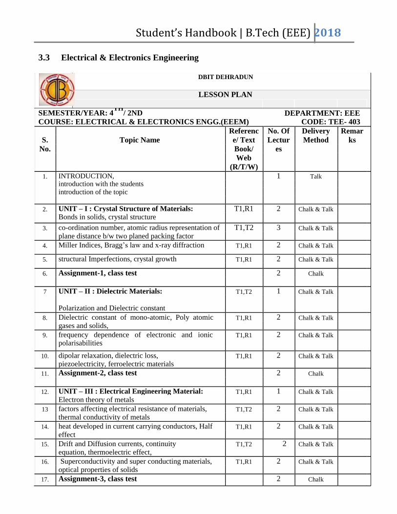
3.3 Electrical & Electronics Engineering
DBIT DEHRADUN
LESSON PLAN
SEMESTER/YEAR: 4TH
/ 2ND DEPARTMENT: EEE COURSE: ELECTRICAL & ELECTRONICS ENGG.(EEEM) CODE: TEE- 403
Referenc No. Of Delivery Remar
S. Topic Name e/ Text Lectur Method ks
No. Book/ es
Web
(R/T/W)
1. INTRODUCTION, 1 Talk
introduction with the students
introduction of the topic
2. UNIT – I : Crystal Structure of Materials: T1,R1 2 Chalk & Talk
Bonds in solids, crystal structure
3. co-ordination number, atomic radius representation of T1,T2 3 Chalk & Talk
plane distance b/w two planed packing factor
4. Miller Indices, Bragg’s law and x-ray diffraction T1,R1 2 Chalk & Talk
5. structural Imperfections, crystal growth T1,R1 2 Chalk & Talk
6. Assignment-1, class test 2 Chalk
7 UNIT – II : Dielectric Materials: T1,T2 1 Chalk & Talk
Polarization and Dielectric constant
8. Dielectric constant of mono-atomic, Poly atomic T1,R1 2 Chalk & Talk
gases and solids,
9. frequency dependence of electronic and ionic T1,R1 2 Chalk & Talk
polarisabilities
10. dipolar relaxation, dielectric loss, T1,R1 2 Chalk & Talk
piezoelectricity, ferroelectric materials
11. Assignment-2, class test 2 Chalk
12. UNIT – III : Electrical Engineering Material: T1,R1 1 Chalk & Talk
Electron theory of metals
13 factors affecting electrical resistance of materials, T1,T2 2 Chalk & Talk
thermal conductivity of metals
14. heat developed in current carrying conductors, Half T1,R1 2 Chalk & Talk
effect
15. Drift and Diffusion currents, continuity T1,T2 2 Chalk & Talk
equation, thermoelectric effect,
16. Superconductivity and super conducting materials, T1,R1 2 Chalk & Talk
optical properties of solids
17. Assignment-3, class test 2 Chalk

Student’s Handbook | B.Tech (EEE) 2018
18. UNIT – IV : Magnetic Material: T1,R1 1 Chalk & Talk
Origin of permanent magnetic dipoles in matters,
19. Classification Diamagnetism, Paramagnetism, T1,R1 3 Chalk & Talk
Ferromagnetism, Antiferromagnetismand
Ferrimagnetism, magnetostriction
20. Properties of magnetic materials, soft and hard T1,R1 2 Chalk & Talk
magnetic materials, permanent magnetic materials.
21. Assignment-4, class test 2 Chalk
22. MISCELLANEOUS ASSIGNMENT 1 Chalk
23. REVISION 2 Chalk
Total Lectures: 42
TEXT BOOKS:
1 A.J. Dekker,”Electrical Engineering Materials” Prentice Hall of India
2 Solymar, “Electrical Properties of Materials” Oxford University Press.
3. Ian P. Hones,” Material Science for Electrical and Electronic Engineering,” Oxford
University Press.
Department of Electrical & Electronics Engineering

Student’s Handbook | B.Tech (EEE) 2018
3.4 Microprocessor & its Application
DBIT DEHRADUN
LESSON PLAN
SEMESTER/YEAR: 4th
/2nd
DEPARTMENT: ECE COURSE: MICROPROCESSORS AND ITS APPLICATION CODE: TEE-404
Referenc No. Of Delivery Remar
S. Topic Name e/ Text Lectur Method ks
No. Book/ es
Web
(R/T/W) 1. Introduction to multistage Amplifiers T1,R1 1 Board and
marker
2. Need for multistage amplifer T1,R1 1 Board and
marker
3. History of computers T1,T2 1 Board and
marker
4. Timing and control T1,R1 1 Board and
marker
5. Introduction to Memory device T1,R1 1 Board and
marker
6. Category of memory T1,T2 1 Board and
marker
7 Introduction to 8-bit Microprocessors(8085) T1,R1 1 Board and
marker
8. Architecture of 8085 T1,R1 1 Board and
marker
9. Instruction set of 8085 T1,R1 1 Board and
marker
10. Adessing Modes T1,R1 1 Board and
marker
11. Assembly Language Programming T1,R1 1 Board and
marker
12. Introduction to 16-bit Microprocessors (8086) T1,R1 1 Board and
marker
13 Architecture of 8086 T1,R1 1 Board and
marker
14. Physical address in 8086 T1,T2 1 Board and
marker
15. Segmentation of Memory T1,R1 1 Board and
marker
16. Memory Organization T1,R1 1 Board and
marker
17. Bus Cycle in 8086 T1,R1 1 Board and
marker
18. Instruction set in 8086 T1,R1 1 Board and
marker
19. Addressing modes in 8086 T2,R1 1 Board and
marker
Department of Electrical & Electronics Engineering

Student’s Handbook | B.Tech (EEE) 2018
20. Difference between 8085 & 8086 T2 1 Board and
marker
21. Assembler Directives T2,R1 1 Board and
marker
22. Assembly Language Programming of 8086 T2 1 Board and
marker
23. Introduction of Peripheral Interfacing T2,R1 1 Board and
marker
24. Types of transmission T2 1 Board and
marker
25. 8257(DMA) T2,R1 1 Board and
marker
26. 8255(PPI) T2 1 Board and
marker
27. Serial Data transfer(8251) T1 1 Board and
marker
28. Keyboard –display controller (8279) R2 1 Board and
marker
29. Programmable Priority Controller (8259) T1,T2 1 Board and
marker
30. Introduction 8253 T2 1 Board and
marker
31. ADC T1 1 Board and
marker
32. Application of peripheral devices T1,R1 1 Board and
marker
33 Introduction to Advanced Microprocessors T1 1 Board and
marker
34 Introduction to 80186 T1,T2 1 Board and
marker
35 Introduction To 80286 T1 1 Board and
marker
36 Introduction To 80386 T1 1 Board and
marker
37 Introduction To 80486 T2.R2 1 Board and
marker
38 Pentium microprocessors T1R1 1 Board and
marker
39 Introduction To Microcontroller (8051) T1,R1 1 Board and
marker
Total Lectures: 40
TEXT BOOKS:
[T1] Gaonkar, Ramesh S, “Microprocessor Architecture, programming and applications with the 8085” Pen ram International Publishing 5th Ed. [T2] Ray, A.K. & Burchandi, K.M., “Advanced Microprocessors and Peripherals: Architecture, Programaming and Interfacing” Tata Mc. Graw Hill.
REFERENCE BOOKS: [R1] Liu and Gibson G.A., “Microcomputer Systems: The 8086/8088 Family” Prentice
[R2]Uffenbeck, John, “Microcomputers and Microprocessors” PHI/ 3rd Edition.
Department of Electrical & Electronics Engineering

Student’s Handbook | B.Tech (EEE) 2018
3.6 Signal & Systems
DBIT DEHRADUN
LESSON PLAN
SEMESTER/YEAR: 4th
/2Nd
DEPARTMENT: ECE
COURSE:SIGNAL&SYSTEM CODE: TEC-402
Referenc No. Of Delivery Remar
S. Topic Name e/ Text Lectur Method ks
No. Book/ es
Web
(R/T/W)
1. Signals and Systems: T1/R1 1 Chalk & Talk
2. Continuous-time and discrete-time Signals T1/R1 1 Chalk & Talk
3. Transformations of the Independent Variable T1/R1 1 Chalk & Talk
4. Exponential and Sinusoidal Signals, T1/R1 1 Chalk & Talk
5. Continuous-Time and Discrete-Time LTI Systems T1/R1 1 Chalk & Talk
6. LTI Systems properties T1/R1 2 Chalk & Talk
7. convolution sum T1/R1 2 Chalk & Talk
8. convolution integrals T1/R1 2 Chalk & Talk
9. LTI System described by differential and difference T1/R1 2 Chalk & Talk
equation
10. Fourier series and Fourier Transformer: T1/R1 1 Chalk & Talk
11. The response of LTI Systems to Complex T1/R1 2 Chalk & Talk
Exponentials
12 Fourier Series Representation of T1/R1 2 Chalk & Talk
Continuous-time Periodic Signals
13. their Properties T1/R1 2 Chalk & Talk
14. Continuous time T1/R1 2 Chalk & Talk
and discrete time Fourier Transforms
15. their properties T1/R1 1 Chalk & Talk
16. System Characterized by Linear Constant T1/R1 1 Chalk & Talk
Coefficient Differential equations and Difference
equation.
17. Time and Frequency Characterization of Signals T1/R1 1 Chalk & Talk
and Systems:
18. Magnitude Phase Representation of the Fourier T1/R1 1 Chalk & Talk
Transform,
19. Magnitude Phase Representation of the Frequency T1/R1 2 Chalk & Talk
response of LTI systems
20. Time T1/R1 2 Chalk & Talk
domain Properties of Ideal Frequency Selective

Student’s Handbook | B.Tech (EEE) 2018
filter
21. Time Domain T1/R1 1 Chalk & Talk
and Frequency Domain aspects of Non ideal filters
22. First Order and T1/R1 3 Chalk & Talk
Second Order Continuous Time and Discrete time
Systems.
23. Sampling and Laplace Transform: T1/R1 1 Chalk & Talk
24. Signal representation by samples T1/R1 1 Chalk & Talk
25. sampling theorem, T1/R1 1 Chalk & Talk
26. Impulse train sampling, sampling of discrete time T1/R1 2 Chalk & Talk
signals,
27. discrete time processing of continuous time signals. T1/R1 1 Chalk & Talk
28. Laplace Transform, T1/R1 2 Chalk & Talk
29. Region of convergence, inverse Laplace Transform T1/R1 1 Chalk & Talk
30. Analysis and characterization of LTI System T1/R1 2 Chalk & Talk
31. Unilateral Laplace transform. T1/R1 2 Chalk & Talk
32. Z-Transform: Z-Transform, T1/R1 2 Chalk & Talk
33. Region of convergence T1/R1 1 Chalk & Talk
34. Inverse Ztransform, T1/R1 2 Chalk & Talk
35. analysis and characterization of LTI system T1/R1 2 Chalk & Talk
36. Block diagram T1/R1 2 Chalk & Talk
representation, Unilateral Z-transform
Total Lectures: 56
TEXT BOOKS:
[T1] Signals and Systems : Pearson New International Edition” by Alan V Oppenheim, S. Hamid, Alan S. Willsky
[T2] Signals And Systems” by H P Hsu
REFERENCE BOOKS: [R1] “Signals And Systems” by Barry Van Veen Simon Haykin
[R2] “Circuits and Systems: A Modern Approach” by A. Papoulis
Department of Electrical & Electronics Engineering

Student’s Handbook | B.Tech (EEE) 2018
4 Assignments
4.1 EMEC- II
DEV BHOOMI INSTITUTE OF TECHNOLOGY, DEHRADUN
ASSIGNMENT SHEET
Course Name: Electromechanical Energy
Assignment No. 1
Conversion-II
Course Code:TEE-501 Branch: EEE Semester: IV
Unit/Title: 3/ Three Phase Induction Machine-I Date of Issue: Date of Submission:
1. Explain the two types of rotors of Induction Motors?
2. What is the principle of operation of Induction motor?
3. How will you change the direction of rotation of three phase induction motor?
4. What is slip?
5. List the application of slip ring induction motor?
6. Why an Induction motor is called asynchronous motor?
7. State the effect of rotor on starting torque?
8. What is crawling and cogging of an induction machine?
9. State the effect of rotor resistance on starting Torque?
10. A 3300V, 10 pole, 50 Hz three phase star connected induction motor has slip ring rotor
resistance per phase is 0.015 ohms and standstill reactance per phase is 0.25 ohm. If
the motor runs at percent slip on full load, find.
i. Slip.
ii. Speed of motor.
iii. Mechanical power developed.
iv. Rotor copper loss per phase.
v. Rotor resistance

Student’s Handbook | B.Tech (EEE) 2018
DEV BHOOMI INSTITUTE OF TECHNOLOGY, DEHRADUN
ASSIGNMENT SHEET
Course Name: Electromechanical Energy
Assignment No. 2
Conversion -II
Course Code:TEE-501 Branch: EEE Semester: IV
Unit/Title: 4/ Three Phase Induction Machine-II Date of Issue: Date of Submission:
1. What is the function of starter?
2. List the disadvantages of autotransformer starter.
3. What are the advantages of DOL starter?
4. Name the different methods of electric braking?
5. What are the advantages of dynamic braking of an induction motor?
6. How does the slip vary with load?
7. What do you mean by negative slip?
8. How does slip vary with load?
9. Is it possible to start 3 slip ring phase induction motor on load?
10. Discuss the theory of star-delta starter.
Department of Electrical & Electronics Engineering

Student’s Handbook | B.Tech (EEE) 2018
DEV BHOOMI INSTITUTE OF TECHNOLOGY, DEHRADUN
ASSIGNMENT SHEET
Course Name: Electromechanical Energy
Assignment No. 3
Conversion-II
Course Code:TEE-501 Branch: EEE Semester: IV
Unit/Title: I/ Synchronous Machines-I Date of Issue: Date of Submission:
1. State the types of synchronous generator used in hydro electric power station.
2. Name the main parts of synchronous generator.
3. Define regulation of Alternator.
4. Define synchronous speed.
5. How can D C generator be converted into alternator?
6. Describe the principle and construction of slow speed operation generator with
neat diagram?
7. For salient pole synchronous machine, prove the d-axis synchronous reactance Xd, can
be obtained from its OCC and SCC. Neglect armature resistance.
8. Explain the condition for parallel operation of 3 phase alternator with neat diagram.
9. A 3 phase 16 pole alternator has star connected winding with 144 slots and 10 conductors
per slot. The flux per pole 0.04wb and is sinusoidaly distributed. The speed is 375rpm.
Find the frequency, phase emf and line emf. The coil span is 160° electrical.
10. A three phase 16 pole alternator has star connected 2000KA for certain field excitation.
With the same excitation the open circuit voltage was 900V. The resistance between a pair
of terminal was 0.12 ohms. Find the full load regulation at UPF and 0.8pf lagging. Draw
the phasor diagram.
Department of Electrical & Electronics Engineering

Student’s Handbook | B.Tech (EEE) 2018
DEV BHOOMI INSTITUTE OF TECHNOLOGY, DEHRADUN
ASSIGNMENT SHEET
Course Name: Electromechanical Energy
Assignment No. 4
Conversion -II
Course Code:TEE-501 Branch: EEE Semester: IV
Unit/Title: 2/ Synchronous Motor-II Date of Issue: Date of Submission:
1. What are the main parts of synchronous motor?
2. Explain why synchronous motor has no starting torque?
3. What is synchronous capacitor?
4. Synchronous motor always run at synchronous speed. Why?
5. What is hunting?
6. What are V-curves?
7. What are the uses of damper winding in a synchronous motor?
8. How can you operate synchronous motor at any desired power factor?
9. What will be the power factor if synchronous motor is operated under excited?
10. Explain the method of starting of synchronous motor against high torque loads. 11. A synchronous motor having 40% reactance and negligible resistance is to be operated
at rated voltage at UPF, 0.8pf lag 0.6pf lag, 0.8pf lead and 0.6pf lead. What are the true values of induced emf?
12. A 75KW, 400V, 4 pole, 3 Phase , star connected synchronous motor runs at 1500rpm. The excitation is constant and corresponding to open circuit voltage of 2000V. The
resistance is neglegible in comparision with synchronous reactance of 3.5ohms/ph. For an armature current of 200A. Determine
i. Power Factor
ii. Power Input iii. Torque developed.
Department of Electrical & Electronics Engineering
Student’s Handbook | B.Tech (EEE) 2018
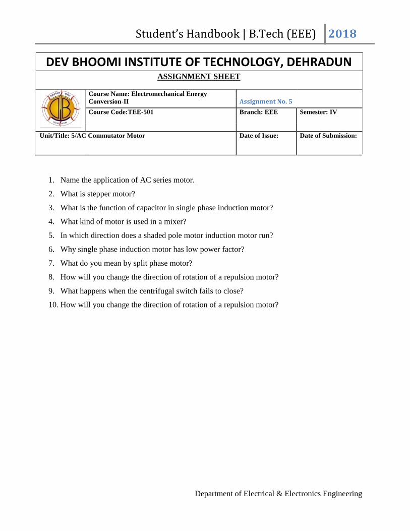
DEV BHOOMI INSTITUTE OF TECHNOLOGY, DEHRADUN
ASSIGNMENT SHEET
Course Name: Electromechanical Energy
Assignment No. 5
Conversion-II
Course Code:TEE-501 Branch: EEE Semester: IV
Unit/Title: 5/AC Commutator Motor Date of Issue: Date of Submission:
1. Name the application of AC series motor.
2. What is stepper motor?
3. What is the function of capacitor in single phase induction motor?
4. What kind of motor is used in a mixer?
5. In which direction does a shaded pole motor induction motor run?
6. Why single phase induction motor has low power factor?
7. What do you mean by split phase motor?
8. How will you change the direction of rotation of a repulsion motor?
9. What happens when the centrifugal switch fails to close?
10. How will you change the direction of rotation of a repulsion motor?
Department of Electrical & Electronics Engineering

Student’s Handbook | B.Tech (EEE) 2018
4.3 Electrical & Electronics Engineering
DEV BHOOMI INSTITUTE OF TECHNOLOGY, DEHRADUN
ASSIGNMENT SHEET
Course Name: EEEM Assignment No. 1
Course Code:TEE-401 Branch: EEE Semester: IV
Unit/Title: 1/ Crystal structure of materials Date of Issue: Date of Submission:
1. Explained the atomic radius representation of plane distance b/w two planed packing factor.
2. With the help of energy band structure, explain the insulator, semiconductor and insulator.
3. Explain Bragg’s law. How Bragg’s equation can be used to determine the lattice parameters?
4. What is the electronic configuration of the two constituents of the compound when they are in
solid form?
5. An atom has a partially filled outer shell, but can easily accept more electrons to fill it. How
would you describe this atom?
6. What type of bonding do silicon and diamonds have in common?
7. What does the term "polycrystalline" mean?
8. Assuming iron (Fe) has a lattice parameter, a, of 0.287 nm, what is the atomic radius and atomic
density of an iron crystal?
9. Calculate the packing fraction of the face-centered cubic structure.
10. Calculate the atomic density of a simple orthorhombic crystal with a = 1.046 nm, b = 1.288
nm and c = 2.448 nm.
Department of Electrical & Electronics Engineering

Student’s Handbook | B.Tech (EEE) 2018
DEV BHOOMI INSTITUTE OF TECHNOLOGY, DEHRADUN
ASSIGNMENT SHEET
Course Name: EEEM Assignment No. 2
Course Code:TEE-401 Branch: EEE Semester: IV
Unit/Title: 2/ Dielectric Materials Date of Issue: Date of Submission:
1. Briefly discuss the polarization phenomenon in dielectric materials.
2. Is the relative dielectric constant (ε r) depends on the atomic size of dielectric materials? Explain.
3. What is dielectric material? Mention the uses of dielectric materials.
4. Define the following terms (i) Dielectric Polarization, (ii) Polaris ability, (iii) Dielectric
Constant, (iv) Spontaneous polarization, (v) Electric susceptibility
5. Give name of 3 each – Ferro and Piezo- electric materials. Also point out their most important
uses in industry.
6. What is dielectric loss? Define loss-tangent of dielectric?
7. What should be the nature of relative dielectric constant (ε r) under A.C. field? How it is
related with the dielectric loss in the system?
8. What should be the effect on relative dielectric constant of ionic solid materials, when
placed under optical radiation?
Department of Electrical & Electronics Engineering

Student’s Handbook | B.Tech (EEE) 2018
DEV BHOOMI INSTITUTE OF TECHNOLOGY, DEHRADUN
ASSIGNMENT SHEET
Course Name: EEEM Assignment No. 3
Course Code:TEE-401 Branch: EEE Semester: IV
Unit/Title: 3/ Electrical Engineering materials Date of Issue: Date of Submission:
1. How to arrive at the highest temperature superconductivity?
2. Obtain an expression for current flowing through a metal with the help of Classical free electron
theory.
3. Explain the temperature dependence of static dielectric constant.
4. Explain Meissen effect. Mention and explain the classification of super conductors (soft & hard).
5. What is meant by the potential barrier across the junction? What is its significance?
6. What is Hall Effect? Obtain the expression for the Hall Effect?
7. Define Drift and Diffusion currents.
8. Define Relaxation time and Relaxation frequency for a dielectric material.
Department of Electrical & Electronics Engineering

Student’s Handbook | B.Tech (EEE) 2018
DEV BHOOMI INSTITUTE OF TECHNOLOGY, DEHRADUN
ASSIGNMENT SHEET
Course Name: EEEM Assignment No. 4
Course Code:TEE-401 Branch: EEE Semester: IV
Unit/Title: 4/ Magnetic Material Date of Issue: Date of Submission:
1. What is Bohr magneton ? Calculate its value.
2. What are the major technical/industrial uses of magnetic materials?
3. Dia-magnetic materials have –ve susceptibity – Explain briefly.
4. What are the advantages of soft ferrites in the applications of transformer cores?
5. Briefly describe the temperature effect (above and below of Curie temperature) on ferromagnetic
materials with the help of Weiss Theory.
6. What are differences of (a) Soft magnetic and (b) Hard magnetic materials? Give three
(3) examples. Also point out their uses.
7. Describe anti- ferromagnetism and Ferri-magnetism.
8. Why is permanent magnet material we concentrate our attention on its demagnetization
characteristics, (the magnetic behavior of a material in the second quadrant of the
hysteresis loop)?
9. What is meant by fringing?
10. When a steady current through a coil can establish a certain magnetic field, why do we need
permanent magnets?
11. After magnetic saturation is reached, is it possible to increase further the flux density by
increasing the applied mmf ? Explain.
Department of Electrical & Electronics Engineering

Student’s Handbook | B.Tech (EEE) 2018
4.4 Microprocessor & its Application
DEV BHOOMI INSTITUTE OF TECHNOLOGY, DEHRADUN
ASSIGNMENT
Course Name: Microprocessor and its
Assignment No. 1
Application
Course Code:TEC-404 Branch: ECE Semester: IV
Unit/Title: 1/ I Date of Issue: Date of Submission:
Q.1 Write the theory with actual fact of Evolution of Microprocessor.
Q.2 what is Microprocessor? Differentiate between microprocessor and microcontroller.
Q.3 List few applications of microprocessor-based system
Q.4 Mention the purpose of SID and SOD lines.
Q.5 what is an Opcode?
Q.6 what is an Operand?
Q.7 how many operations are there in the instruction set of 8085?
Q.8 Explain the purpose of the I/O instructions IN and OUT.
Q.9 what is the difference between the shifts and rotate instructions?
Q.10 How many address lines in a 4096 x 8 EPROM CHIP? Q.11 what are the control signals used for DMA operation Q.12What is meant by Wait State? Q.13 what is meant by polling?
Q.14 what is meant by interrupt?
Q.15 what is a microcomputer?
Student’s Handbook | B.Tech (EEE) 2018
DEV BHOOMI INSTITUTE OF TECHNOLOGY, DEHRADUN
ASSIGNMENT
CourseName:Microprocessor andits
Assignment No. 2
Application
Course Code:TEC-404 Branch: ECE Semester: IV
Unit/Title: 1/ II Date of Issue: Date of Submission:
Q1. Explain the architecture of microprocessors 8085.
Q2. Explain the pin diagram of 8085. Q3.Explain the requirement of a program counter, stack pointer and status flags in the
architecture of 8085 microprocessor. Q4.Explain the memory mapped I/O addressing scheme.
Q5.Draw and explain the timing diagram of memory read cycle.
Q6. Draw and explain the timing diagram of memory write cycle with example.
Q7. Draw and explain the timing diagram of opcode fetch cycle.
Q8. Explain the direct addressing modes and indirect addressing modes of 8085 with example. Q9. Assume that the accumulator contents data bytes 88 hand instruction MOV C, A 4FH
is fetched. List the steps decoding and executing the instruction. Q10 Draw the functional block diagram of 8085 microprocessor and explain. Q11.Write a Program to Perform the following functions and verify the output steps: a. Load the
number 5CH in register D b. Load the number 9E H in register C . Increment the Contents of
register C by one. d. Add the contents of register C and D and Display the sum at output port1. Q13.Write an assembly language program to find out the largest number from a given
unordered array of 8 bit numbers, stored in the locations starting from a known address.
Department of Electrical & Electronics Engineering

Student’s Handbook | B.Tech (EEE) 2018
DEV BHOOMI INSTITUTE OF TECHNOLOGY, DEHRADUN
ASSIGNMENT
CourseName:Microprocessor andits
Assignment No. 3
Application
Course Code:TEC-404 Branch: ECE Semester: IV
Unit/Title: III Date of Issue: Date of Submission:
Q1.How do 8086 interrupts occur? What are the 8086 interrupt types?
Q2.What is interrupt service routine?
Q3. Define BIOS. Explain PUBLIC .Explain DUP
Q4.What is the purpose of segment registers in 8086?
Q5.Discuss the function of instruction queue in 8086?
Q6. What is the maximum memory size that can be addressed by 8086?
Q7.What are the different flag available in status register of 8086?
Q8. List the various addressing modes present in 8086?
Q9.How single stepping can be done in 8086?
Q10.What is the functions of bus interface unit (BIU) in 8086?
Q11. Differentiate between absolute and linear select decoding?
Q12.What is the functions of status pins in 8086? Q13. Write briefly on LOCK and WAIT for 8086 processor? State the significance of LOCK
signal in 8086? Q14. Explain the function of Execution unit in 8086?
Q15. What do you mean by pipelining in 8086?
Q16.How the 20 bit effective address is calculated in 8086 processor?
Q17.Describe Intel 8086 Microprocessor Architecture
Department of Electrical & Electronics Engineering

Student’s Handbook | B.Tech (EEE) 2018
DEV BHOOMI INSTITUTE OF TECHNOLOGY, DEHRADUN
ASSIGNMENT
CourseName:Microprocessor andits
Assignment No. 4
Application
Course Code:TEC-404 Branch: ECE Semester: IV
Unit/Title: IV Date of Issue: Date of Submission:
Q1.What is the functional types used in control words of 8251? Q2.What is the basic modes of operation of 8255? 8. Write the features of mode 0 in 8255?
Q3.What is the features used mode 1 and mode 2 in 8255?
Q4.What is the signals used in input control signal & output control signal?
Q5.What is the different types of write operations used in 8253?
Q6.What is the modes of operations used in 8253?
Q7.Give the different types of command words used in 8259a?
Q8. Give the operating modes of 8259a? 16. Define scan counter?
Q9. What are the modes used in display modes?
Q10. What is the use of modem control unit in 8251?
Q11. Give the register organization of 8257?
Q12What is the function of DMA address register?
Q13 Interface a 10 or 12-bit D/A converter with an 8-bit microprocessor. Q14 Design a circuit to interface an 8-bit D/A converter with an 8-bit microprocessor and verify the analog output for a digital signal. Q15. Explain the block diagram of the 8155 I/O section and timer. Q16.Explain the function of Handshake signals. What is the difference between setting the
8155 I/O ports in ALT 1 and ALT 3.
Department of Electrical & Electronics Engineering

Student’s Handbook | B.Tech (EEE) 2018
DEV BHOOMI INSTITUTE OF TECHNOLOGY, DEHRADUN
ASSIGNMENT
CourseName:Microprocessor andits
Assignment No. 5
Application
Course Code:TEC-404 Branch: ECE Semester: IV
Unit/Title: V Date of Issue: Date of Submission:
Q1. Explain DJNZ instructions of Intel 8051 microcontroller? Q2. State the function of RS1 and RS0 bits in the flag register of Intel 8051 microcontroller? Q3. Write a program using 8051 assembly language to change the date 55H stored in the lower byte
of the data pointer register to AAH using rotate instruction. Q4. Explain the function of the pins PSEN and EA of 8051
Q5. Explain the 16-bit registers DPTR and SP of 8051
Q6. Name the special functions registers available in 8051.
Q7.Compare Microprocessor and Microcontroller
Q8. List the features of 8051 microcontroller. Q9. Name any four additional hardware features available in microcontrollers when compared
to microprocessors Q10. List out the Hardware Resources available in 8051 .
Q11.When 8051 is reset, all interrupts are disabled. How to enable these interrupts?
Q12.How will you double the baud rate in 8051?
Q13. Write the vector address and priority sequence of 8051 interrupts
Q14. Write a delay routine for 1 millisecond using timer 0 of 8051 for 12 MHz crystal frequency.
Q15.Differentiate RRA and RRCA instruction in 8051 microcontroller
Department of Electrical & Electronics Engineering

Student’s Handbook | B.Tech (EEE) 2018
4.5 Communication Engineering
DEV BHOOMI INSTITUTE OF TECHNOLOGY, DEHRADUN
ASSIGNMENT SHEET
Course Name: Communication Engineering Assignment No. 1
Course Code:TEC-405 Branch: EEE Semester: IV
Unit/Title: I - Amplitude Modulation Date of Issue: Date of Submission:
1. The collector-modulated class C transistor amplifier may experience a certain difficulty. What is
this difficulty? How can it be solved? Show, with a circuit diagram, one of the solutions to this
problem.
2. An AM signal is detected using an envelope detector. The carrier frequency & modulating signal
frequency are 1 MHz & 2 MHz respectively. What will be the value for the time constant of the
envelope detector?
3. A diode detector load consists of 0.01 µF capacitor in parallel with a 5 KΩ resistor. What will be
the maximum depth of modulation without diagonal clipping at modulating frequency of 100 Hz
& 10 KHz?
4. A RF carrier of 10 KV at 1 MHz is amplitude modulated by a 1 KHz signal of 6 KV peak.
The modulation is observed on a CRO calibrated suitably. What will be the voltage indicated?
5. A given AM broad cast station transmits an average carrier power output of 40 KW & uses a
modulation index of 0.707 for sine wave modulation. What is the maximum amplitude of
the output if the antenna is represented by a 50Ω resistive load?
Department of Electrical & Electronics Engineering

Student’s Handbook | B.Tech (EEE) 2018
DEV BHOOMI INSTITUTE OF TECHNOLOGY, DEHRADUN
ASSIGNMENT SHEET
Course Name: Communication Engineering Assignment No. 2
Course Code:TEC-405 Branch: EEE Semester: IV
Unit/Title: II- Angle Modulation Date of Issue: Date of Submission:
1. Explain how frequency modulation may be obtained from a phase modulator. Diagrammatically
compare the amplitude modulation, frequency modulation & phase modulation in respect of change
in amplitude, frequency & phase when the carrier is modulated with a step function.
2. A device with input x (t) & output y (t) is characterized by: y(t)=x2(t). An FM signal with
frequency deviation of 90 KHz & modulating signal bandwidth of 5 KHz is applied to
this device. What is the bandwidth of output signal?
3. Two sinusoidal signals of same amplitude & frequencies 10 KHz & 10.1 KHz are added
together. The combined signal is given to an ideal frequency detector. What will be the output of
the detector?
4. In a FM system, a carrier of 100 KHz is modulated by a sinusoidal signal of 5 KHz. The
bandwidth by Carson’s approximation is 1 MHz. If y (t) = (modulated waveform)3. What will be
the bandwidth of y(t) around 300 MHz & the spacing of spectral components by using Carson’s
approximation?
5. Why should the discriminator tuned frequency in the AFC system be as low as possible?
What lower limit is there on its value? What part can frequency division play here?
Department of Electrical & Electronics Engineering

Student’s Handbook | B.Tech (EEE) 2018
DEV BHOOMI INSTITUTE OF TECHNOLOGY, DEHRADUN
ASSIGNMENT SHEET
Course Name: Communication Engineering Assignment No. 3
Course Code:TEC-405 Branch: EEE Semester: IV
Unit/Title: III- Pulse Communication Date of Issue: Date of Submission:
1. For 10-bit PCM system, the signal to quantization noise ratio is 62 dB. If the number of bits is
increased by 2, then by what factor signal to quantization noise ratio will increase of decrease?
2. For a bit-rate of 8 Kbps, what will be the best possible value of the transmitted frequencies in
a coherent binary FSK system?
3. In a digital communication system employing FSK, the 0 & I bits are represented by sine
waves of 10 KHz & 25 KHz respectively. Find out the bit interval for which these waveforms
will be orthogonal?
4. The input to a linear Delta modulator having a step size = 0.628 is a sine wave with frequency fm &
peak amplitude Em. If the sampling frequency fs= 40 KHz, then what will be the combination of the
sine wave frequency & peak amplitude, where slope overload will take place?
5. Define signal-to-noise ratio & noise figure of a receiver. When might the latter be a more suitable
piece of information than the equivalent noise resistance?
Department of Electrical & Electronics Engineering

Student’s Handbook | B.Tech (EEE) 2018
4.6 Signal & Systems
DEV BHOOMI INSTITUTE OF TECHNOLOGY, DEHRADUN
ASSIGNMENT SHEET
Course Name: Signal & System Assignment No. 1
Course Code: TEC-402 Branch: ECE Semester: IV
Unit/Title: 1/ Signals and Systems:introduction Date of Issue: Date of Submission:
1. Determine whether the following signal is periodic or not? x (t) = sin(2) ½ πt. 2. Differentiate between energy and power signals.
3. Sketch the following signal: x(t) = exp(-a | t | ) for a>0.
Also determine whether the signal is a power signal or energy signal. 4. Prove that the average power of the signal is equal to its root mean square value. 5. Determine whether following are periodic or not and if periodic find its fundamental period.
a. Cos(nπ/3) + sin(nπ/4) b. cos²(nπ/8)
6. Explain the properties of continuous time LTI system. 7. Explain the following.
a. discrete time and continuous time signal
b. causal and non causal system
c. energy and power signal
d. stable and unstable system 8. Define a signal with suitable example. Also differentiate continuous time, discrete time,
analog and digital signals with examples. 9. Explain Continuous time And Discrete time unit step function 10. Determine the linearity, causality and time invariance of the following systems
a. y(t) = t x(t)+2
b. y(n) = cosn x(-n)
Student’s Handbook | B.Tech (EEE) 2018
DEV BHOOMI INSTITUTE OF TECHNOLOGY, DEHRADUN
ASSIGNMENT SHEET
Course Name: Signal & System Assignment No. 2
Course Code: TEC-402 Branch: ECE Semester: IV
Unit/Title: II/ Fourier series and Fourier Date of Issue: Date of Submission:
Transformer:
1. Obtain the Fourier transform of single sided exponential signal: exp - at u (t). Also draw
its spectrum.
2. . Explain the sampling function or sinc function.
3. . Find the Discrete time Fourier Transform (DTFT) of discrete time signal.
x [n] = rnu[n] , for l r l< 1.
4. Obtain the inverse Fourier transform of a rectangular pulse of period T. 5. Discuss with example the convolution property of CTFT. Also give the physical
significance of convolution property of CTFT. 6. Compute the Fourier transform of the function:
a. x(n) = 2nu (- n)
b. x(n) = (1/4)n u(n + 4)
7. Show that the Fourier transform of the convolution of two signals in the time domain can be
given by the product of the Fourier transform of the individual signals in the frequency
domain. 8. Determine the Fourier transform of the signal: x(t) = ½ [δ(t + 1) + δ(t - 1) + δ(t + 1/2) +
δ(t - 1/2)]
9. . Find the Fourier transform
x(t) = t ≥ 0
= 0 t < 0
10. Determine the Fourier transform of the function: y (n) = x(n)*h(n)
Department of Electrical & Electronics Engineering
c. d. e-at

Student’s Handbook | B.Tech (EEE) 2018
DEV BHOOMI INSTITUTE OF TECHNOLOGY, DEHRADUN
ASSIGNMENT SHEET
Course Name: Signal & System Assignment No. 3
Course Code: TEC-402 Branch: ECE Semester: IV
Unit/Title: III/ Time and Frequency Characterization Date of Issue: Date of Submission:
of Signals and Systems:
1. Determine the impulse response of first order continuous time system
2. Discuss second order continuous time LTI system regarding magnitude and phase
characteristics of its transfer function.
3. Discuss magnitude and phase representation of frequency response of continuous time and
discrete time LTI system. Define and discuss group delay
4. We have two discrete time LTI system with frequency responses:
5. State and prove initial and final value theorem
6. Determine the frequency response and magnitude response of the system given by y[n] + 1/2 y[n - 1] = x[n] – x[n - 1]
7. The input signal: x (t) = 4 sin c (2t) cos (4 πt ) is applied to a linear, time invariant system.
Determine and plot the transfer function of the system H (f) such that its response will be y
(t) = sin c (2t). 8. Consider a causal LTI system with frequency response: H(jw) = 1/ (jw + 2) for a particular
input x(t). This system is observed to produce the output y (t) = e
- 2tu (t) - e
-3tu(t) . Determine x(t).
9. Explain the discrete time processing of continuous time signal? To achieve this give the
block diagram of the system.
10. Explain the following terms in brief
a. causality condition for LTI system
b. stability condition for LTI system
Department of Electrical & Electronics Engineering

Student’s Handbook | B.Tech (EEE) 2018
DEV BHOOMI INSTITUTE OF TECHNOLOGY, DEHRADUN
ASSIGNMENT SHEET
Course Name: Signal & System Assignment No. IV
Course Code: TEC-402 Branch: ECE Semester: IV
Unit/Title: IV/ Sampling and Laplace Transform: Date of Issue: Date of Submission:
1 The differential equation of continuous time causal and stable LTI system is expressed as dy (t)/ dt + 5 y (t) = 2 x ( t)
Determine the step response of the system using Laplace transform. 2. State and prove “Sampling Theorem”. 3. What is “Aliasing effect”? find the nyquist rate and nyquist interval for the signal given below
x(t) = 1/2π cos (4000πt) cos (1000πt)
4 State and prove initial and final value theorem 5 Find the inverse laplace transform of: X(s) = 2 / (s + 4).(s - 1) for all possible signal
convergence. 6 Define the following terms
a. nyquist rate b. sampling rate c. Under, critical and over sampling.
7 What is aliasing phenomena? How can aliasing phenomena be determined? 8 Determine the laplace transform and associated ROC and pole zero plot for each of the
following function of time
a. x(t) = e-2t
u(t) + e-3t
u(t)
b. x(t) = t e-2t
c. x(t) = δ (3t) + u(t)
9 Find the nyquist rate and nyquist frequency for each of the following signals
a. x(t) = 4 sin c 2 (200 πt)
b. x(t) = -10 sin (40 πt) cos (300 πt). 10 Determine the condition as the sampling interval T so that the signal
x(t) = cos (2 πt) sin(πt)/ πt + 3 sin (6 πt) sin(2 πt)/ πt is uniquely represented by its samples.
Department of Electrical & Electronics Engineering

Student’s Handbook | B.Tech (EEE) 2018
DEV BHOOMI INSTITUTE OF TECHNOLOGY, DEHRADUN
ASSIGNMENT SHEET
Course Name: Signal & System
Assignment No. V
Course Code: TEC-402 Branch: ECE Semester: IV
Unit/Title: V/ Z-Transform Date of Issue: Date of Submission:
1.Define Z transform
.2.Define ROC.
3. Find Z transform of x(n)=1,2,3,4 4. State the convolution property of Z transform.
5. What is z-transform of (n-m)?
6. State initial value theorem.
7. List the methods of obtaining inverse Z transform.
8. Obtain the inverse z transform of X(z)=1/z-a,|z|>|a|
9.Give the relationship between z-transform and Fourier transform.
10. Determine the inverse z transform of the following
function x(z)=1 / (1 + z -1) (1 –z -1 )2 ROC : |Z>1|
11. Find the z-transform of x(n) = an u(n) and for unit impulse signal
Department of Electrical & Electronics Engineering

Student’s Handbook | B.Tech (EEE) 2018
5 Tutorial Sheets
5.1 EMEC- II
DEV BHOOMI INSTITUTE OF TECHNOLOGY, DEHRADUN
TUTORIAL SHEET
Course Name: Electromechanical Energy
Tutorial Sheet No. 1
Conversion- II
Course Code:TEE-501 Branch: EEE Semester: IV
Unit/Title: 3/ Induction Machine-I Date of Discussion:
Q1: A three phase 4 pole 50Hz induction motor runs at 1460 rpm. Find its % slip. Q2: A 12 pole 3 phase alternator driver at speed of 500 rpm. Supplies power to an 8 pole, 3 phase induction motor. If the slip of motor is 0.03p.u, calculate the speed. Q3: A motor generates set used for providing variable frequency supply consists of a 3 phase
synchronous and 24 pole 3 phase synchronous generator. The motor generate set is fed from 25 Hz, 3 phase AC supply. A 6 pole 3 phase induction motor is electrically connected to the terminal of
the synchronous generator and runs at a slip of 5 %. Find i. The frequency of generated voltage of synchronous generator.
ii. The speed at which induction motor is running.
Q4: A 3 phase, 4 pole induction motor is supplied from 3 phase 50HZ AC supply. Find i. Synchronous speed.
ii. Rotor speed when slip is 4 %. iii. The rotor frequency when runs at 600 rpm.
Q5: A three phase induction motor has starting torque of 100% and a maximum torque of 200 % of the full load torque. Determine:
a. Slip at which maximum torque occurs. b. Full load slip. c. Rotor current at starting in per unit of full- load current.
Q6: A 3-phase, 6-pole, 50Hz induction motor has a slip of 1 % at no load, and 3% at full load. Determine
a. Synchronous Speed. b. No- load speed. c. Full load speed. d. Frequency of rotor current at full load. e. Frequency of rotor current at full load.

Student’s Handbook | B.Tech (EEE) 2018
DEV BHOOMI INSTITUTE OF TECHNOLOGY, DEHRADUN
TUTORIAL SHEET
CourseName:Electromechanical Energy
Tutorial Sheet No. 2
Conversion- II
Course Code:TEE-501 Branch: EEE Semester: IV
Unit/Title: 4/ Induction Machines-II Date of Discussion:
Q1: A small three phase Induction motor has a short-circuit current equal to 5 times the full load current. Determine the starting current and starting torque if resistance starter is used to reduce the impressed voltage to 60% of normal voltage. The full load slip is 0.05.
Q2: Find the ratio of starting to full load current for a 10 KW, 400V three phase Induction motor with star- Delta starter, given that the full load efficiency is 0.86, the full load power factor is 0.8 and short circuit current is 30A at 100V. Q3:Calculate the reduction in starting current and starting torque when supply voltage to a cage motor is 75% instead of 100%. Q4: A three phase Delta- connected cage type induction motor when connected to 400V, 50Hz supply takes a starting current of 100A in each stator phase. Calculate:
i. The line current for DOL starting. ii. Line and phase currents for Star-delta starting.
Q5: A cage induction motor has a full-load slip of 0.05. The motor starting current at rated voltage is 5.5 times its full load current. Find the tapping on the auto-Transformer starter which should give full- load torque at start. Also find the line current at starting.
Department of Electrical & Electronics Engineering

Student’s Handbook | B.Tech (EEE) 2018
DEV BHOOMI INSTITUTE OF TECHNOLOGY, DEHRADUN
TUTORIAL SHEET
CourseName:Electromechanical Energy
Tutorial Sheet No. 3
Conversion- II
Course Code:TEE-501 Branch: EEE Semester: IV
Unit/Title: 1/ Synchronous Machine- I Date of Discussion:
Q1: A 3-phase, star connected alternator is rated at 1600KVA., 16500V. The armature effective resistance and synchronous reactance are 1.5 Ω and 30 Ω respectively per phase. Calculate the percentage regulation for a load of 128KW at power factor of
a. 0.8 Lead
b. 0.8 lagging
c. UPF
Q2: A 550V, 55KVA, single phase alternator has an effective resistance of 0.2 Ω. A field current of 10A produces an armature current of 200A on short circuit and an emf of 450V on open
circuit. Calculate the synchronous reactance and voltage regulation at full load with power factor
of 0.8 lagging.
Q3: A synchronous generator has a synchronous reactance of 1.2 pu. It is running overexcited with
an excitation voltage of 1.5pu and supplies a synchronous power of 0.6pu to the bus. If prime mover torque is increased by 1%, by how much will the synchronous power P and reactive power
Q change.
Q4: A 2 MVA, 3-phase, 8pole alternator runs at 750rpm in parallel with other machines on 6000V
busbars. Find the synchronizing power on full load at power factor 0.8 lagging per mechanical degree of displacement and the corresponding synchronizing torque. The synchronous reactance of
the machine is 6Ω per phase.
Q5: The stator of a three-phase, 8 pole, 750 rpm alternator has 72 slots, each of which contains 10 conductors. Calculate the rms value of the emf per phase if the flux per pole is 0.1 Wb sinusoidally distributed. Assume full-pitch coils and a winding distribution factor of 0.96.
Department of Electrical & Electronics Engineering

Student’s Handbook | B.Tech (EEE) 2018
DEV BHOOMI INSTITUTE OF TECHNOLOGY, DEHRADUN
TUTORIAL SHEET
CourseName:Electromechanical Energy
Tutorial Sheet No. 4
Conversion- II
Course Code:TEE-501 Branch: EEE Semester: IV
Unit/Title: 1/ Synchronous Machine- II Date of Discussion:
Q1: A 2000V,3 phase, star connected synchronous motor has an effective resistance and synchronous reactance of 0.2 Ω and 2.2 Ω per phase respectively. The input is 800KW at normal voltage and the induced line emf is 2500V. Calculate the line current and power factor.
Q2: The efficiency of a 3 phase, 400V, Star connected synchronous motor is 95% and it takes 24A at full load and unity power factor. What will be the induced emf and total mechanical power developed at full load and 0.9pf leading? The synchronous impedance per phase is (0.2+j2) Ω.
Q3A 6600V, 3-phase, star connected synchronous motor draws a full-load surrent of 80A at 0.8pf leading. The armature resistance is 2.2 Ω and synchronous reactance 22 Ω per phase. If the stray losses of the machine are 3200W, determine:
a. Emf induced
b. The output power
c. Efficiency.
Q4: Asynchronous reactance per phase of a 3 phase star connected 6600V synchronous motor is 20
Ω. For a certain load the input is 900KW at normal voltage and the induced line emf is 8500V.
Determine the line current and power factor.
Q5 A 3 phase, 5000KVA,11KV,50Hz, 1000rpm star connected synchronous motor operates at full load at a power factor of 0.8pf leading.
Department of Electrical & Electronics Engineering

Student’s Handbook | B.Tech (EEE) 2018
5.3 Electrical & Electronics Engineering
DEV BHOOMI INSTITUTE OF TECHNOLOGY, DEHRADUN
TUTORIAL SHEET
Course Name: EEEM Tutorial Sheet No. 1
Course Code: TEE-403 Branch: EEE Semester: IV
Unit/Title: 1/ Crystal Structure of Materials Date of Discussion:
Q1: Inert gases have completely filled outer cell yet the boiling point of these increases with the atomic
number. Explain why it is so
Q2: Find out the indices of the direction joining following points in a cubic lattice:
(a) 1,1,1 with 1,1,2 (b) -1,1,1 with -3, 2, 1 (c) 1,1,2 with 3,2,-1
Q3: Show the atomic arrangements in (111) plane of face Centre cubic structure and show the
following directions 11 0, 1 01, 011 , 2 11, 12 1, 112
Q4: Estimate the density of platinum and lead from their lattice parameters at room temperature. Both are
FCC. Compare the theoretical density with experimental values. Which is closer? Why?
Q5: What is the basic difference between engineering & stereographic projections? Show with the help of
a neat sketch the relation between a plane and a pole drawn on a projection plane.
Department of Electrical & Electronics Engineering

Student’s Handbook | B.Tech (EEE) 2018
DEV BHOOMI INSTITUTE OF TECHNOLOGY, DEHRADUN
TUTORIAL SHEET
Course Name: EEEM Tutorial Sheet No. 2
Course Code: TEE-403 Branch: EEE Semester: IV
Unit/Title: 2/Dielectric Material Date of Discussion:
Q1: Using Gauss’s Law, calculate the electric field everywhere.
Q2: Compute the electric potential difference ΔV between the two conductors.
.
Department of Electrical & Electronics Engineering
Student’s Handbook | B.Tech (EEE) 2018
DEV BHOOMI INSTITUTE OF TECHNOLOGY, DEHRADUN
TUTORIAL SHEET
Course Name: EEEM Tutorial Sheet No. 3
Course Code: TEE-403 Branch: EEE Semester: IV
Unit/Title: 3, 4/ Electrical Engg. material Date of Discussion:
Q1: Discuss electrical properties of insulating materials.
Q2: Classify the different types of insulating materials with reference to their limiting safe temperatures
for use.
Q3: Give the properties and application of brass and bronze, asbestos and glass.
Q4: Explain the factors affecting permeability and hysterisis loss.
Department of Electrical & Electronics Engineering
Student’s Handbook | B.Tech (EEE) 2018
5.4 Microprocessor & its Application
DEV BHOOMI INSTITUTE OF TECHNOLOGY, DEHRADUN
TUTORIAL SHEET
Course Name: Microprocessor and its Tutorial No. 1
Applications
Course Code:TEE-404 Branch: ECE Semester: IV
Faculty :Mr. LOKENDAR KUMAR
Unit/Title: 1/ I Date of Issue: Date of Submission:
Q1. Study 8085 based microprocessor system with the help experimental kit.
Q2. Detail study of 8086 and 8086A based microprocessor system with the help experimental kit.
Q3. Study the Pentium Processor with their specification.
Q4. Addition of 2 - 8 bit numbers with the help experimental kit.
Q5. Subtraction of 2 - 8 bit numbers with the help experimental kit.
Department of Electrical & Electronics Engineering

Student’s Handbook | B.Tech (EEE) 2018
DEV BHOOMI INSTITUTE OF TECHNOLOGY, DEHRADUN
TUTORIAL SHEET
CourseName:Microprocessor andits Tutorial No. 2
Applications
Course Code:TEE-404 Branch: ECE Semester: IV
Faculty :Mr. LOKENDAR KUMAR
Unit/Title: 1/ II Date of Issue: Date of Submission:
Q1. To develop and run a program for arranging in ascending/descending order of a set of
numbers
Q2. Write a program for finding out the largest/smallest number from a given set of numbers
with the help of experimental kit.
Q3. Write a program to study multiplication/division of given numbers.
Q4. Write a program to study conversion of temperature from 0 F to 0 C and vice-versa.
Q5. Write a program Addition of 2 - 16 bit numbers on kit.
Q6. Write a program Subtraction of 2 – 16 bit numbers on kit.
Department of Electrical & Electronics Engineering
Student’s Handbook | B.Tech (EEE) 2018
DEV BHOOMI INSTITUTE OF TECHNOLOGY, DEHRADUN
TUTORIAL SHEET
Course Name: Microprocessor and its Tutorial No. 3
Applications
Course Code:TEE-404 Branch: ECE Semester: IV
Faculty :Mr. LOKENDAR KUMAR
Unit/Title: 1/ III Date of Issue: Date of Submission:
Q1. Write a program to arrange the data in ascending order in assembly language..
Q2. Write a program to arrange the data in descending order in assembly language.
Q3. Write a program to execute the Fibonacci Series.
Q4. Write the assembly program for Sum of finite series.
Q5 Write a program to find the Factorial of Given Numbers.
Department of Electrical & Electronics Engineering

Student’s Handbook | B.Tech (EEE) 2018
DEV BHOOMI INSTITUTE OF TECHNOLOGY, DEHRADUN
TUTORIAL SHEET
Course Name: Microprocessor and its Tutorial No. 4
Applications
Course Code:TEE-404 Branch: ECE Semester: IV
Faculty :Mr. LOKENDAR KUMAR
Unit/Title: 1/ IV Date of Issue: Date of Submission:
Q1. What are the functional types used in control words of 8251?
Q2. Write a program to perform computation of square root of a given number.
Q3. Write a program to perform floating point mathematical operations (addition,
subtraction, multiplication and division).
Q4. Write a program Multiplication of 2 - 16 bit numbers.
Q5. Write a program Division of 2 - 16 bit numbers.
Department of Electrical & Electronics Engineering

Student’s Handbook | B.Tech (EEE) 2018
TUTORIAL SHEET
Course Name: Microprocessor and its Tutorial No. 5
Applications
Course Code:TEE-404 Branch: ECE Semester: IV
Faculty :Mr. LOKENDAR KUMAR
Unit/Title: 1/ V Date of Issue: Date of Submission:
Q1. Study the Comparison between the 80286 and 80386.
Q2. Study the Stepper motor rotate forward and reverse direction.
Q3. Discuss the Digital to analog conversion.
Q4. Discuss the Analog to digital conversion
Q5. Study the Interfacing of DMA controller.
Q6. Study the interfacing of PPI.
Q7. Study the interfacing of UART/USART.
Department of Electrical & Electronics Engineering

Student’s Handbook | B.Tech (EEE) 2018
5.5 Communication Engineering
DEV BHOOMI INSTITUTE OF TECHNOLOGY, DEHRADUN
TUTORIAL SHEET
Course Name: Communication Engineering Tutorial Sheet No. 1
Course Code:TEC-405 Branch: EEE Semester: VI
Unit/Title: 1-Amplitude Modulation & Angle Modulation Date of Discussion:
Q.1 Simulation of Communication system using MATLAB.
Q.2 Realization of AM modulator and demodulator using MATLAB.
Q.3 SSB-SC modulation and demodulation using MATLAB.
Q.4 DSB-SC modulation and demodulation using MATLAB.
Department of Electrical & Electronics Engineering

Student’s Handbook | B.Tech (EEE) 2018
DEV BHOOMI INSTITUTE OF TECHNOLOGY, DEHRADUN
TUTORIAL SHEET
Course Name: Communication Engineering Tutorial Sheet No. 2
Course Code: TEC-405 Branch: EEE Semester: VI
Unit/Title: 1 - Amplitude Modulation & Angle Modulation Date of Discussion:
Q.1 Design a Communication system using Simulink.
Q.2 Realization of AM modulator and demodulator with Simulink.
Q.3 SSB-SC modulation and demodulation using Simulink.
Q.4 DSB-SC modulation and demodulation with Simulink.
Department of Electrical & Electronics Engineering
Student’s Handbook | B.Tech (EEE) 2018
DEV BHOOMI INSTITUTE OF TECHNOLOGY, DEHRADUN
TUTORIAL SHEET
Course Name: Communication Engineering Tutorial Sheet No. 3
Course Code: TEC- 405 Branch: EEE Semester: VI
Unit/Title: 3- Pulse Communication Date of Discussion:
Q1: Realization of FM modulator and demodulator using MATLAB.
Q.2 Realization of Pulse code modulation in MATLAB.
Q.3 Realization of Pulse amplitude modulation in MATLAB.
Department of Electrical & Electronics Engineering

Student’s Handbook | B.Tech (EEE) 2018
5.6 Signal & Systems
DEV BHOOMI INSTITUTE OF TECHNOLOGY, DEHRADUN
TUTORIAL SHEET
Course Name : Signal & System Tutorial Sheet No. 1
Course Code: TEC-402 Branch: ECE Semester: IV
Unit/Title: 1/ Signal & System Date of Discussion:
Q1: A discrete time signal x(n) is defined as- x(k) = 1+k/3 -3 ≤ k ≤ -1
1 0 ≤ k ≤ 3 0 otherwise
a) Determine its value and sketch the signal x (k). b) Sketch the signal: x (-k+4).
Q2: . For the following system determine whether or not the system is stable, causal linear, memory less-
a) T[x(n)] = X(n-no) b) T[x(n)] = 3 exp x(n)
Q3: . Determine whether following are periodic or not and if periodic find its fundamental period.
a. Cos(nπ/3) + sin(nπ/4) b. cos²(nπ/8)
Q4: Determine the convolution sum of discrete time signal
Q5: Check whether the following system are time invariant or time variant
a. y(t) = sin x(t) b. y(t) = t x(t)
Department of Electrical & Electronics Engineering

Student’s Handbook | B.Tech (EEE) 2018
DEV BHOOMI INSTITUTE OF TECHNOLOGY, DEHRADUN
TUTORIAL SHEET
Course Name : Signal & System Tutorial Sheet No. 2
Course Code: TEC-402 Branch: ECE Semester: IV
Unit/Title: II/ Fourier series and Fourier Transformer: Date of Discussion:
Q1: . Find the Fourier Transform of gate function as shown in figure.
Q2: Determine the impulse response of h(n) for the system described by the second order difference
equation: y(n) - 4y(n -1) + 4 y(n - 2) = x(n) - x(n - 1)
when y(-1) = x(- 2) = 0
Q3 : Find the Discrete time Fourier Transform (DTFT) of discrete time signal.
x [n] = rnu[n] , for l r l< 1.
Q4: Determine the trigonometric Fourier series for following signals
Q5: Determine the output y (n) of a relaxed linear time invariant with impulse response: h (n) = an u(n), lal < 1
when the input is a unit steps sequence that is x(n) = u(n) .
Department of Electrical & Electronics Engineering

Student’s Handbook | B.Tech (EEE) 2018
DEV BHOOMI INSTITUTE OF TECHNOLOGY, DEHRADUN
TUTORIAL SHEET
Course Name : Signal & System Tutorial Sheet No. 3
Course Code: TEC-402 Branch: ECE Semester: IV
Unit/Title: III/ Time and Frequency Characterization of Date of Discussion:
Signals and Systems:
Q1: Consider a causal LTI system with frequency response: H(jw) = 1/ (jw + 2) for a particular input x(t). This
system is observed to produce the output
y (t) = e- 2t
u (t) - e-3t
u(t) . Determine x(t).
Q2: The input signal: x (t) = 4 sin c (2t) cos (4 πt ) is applied to a linear, time invariant system. Determine and plot the transfer function of the system H (f) such that its response will be y (t) = sin c (2t).
.
Q3 A causal LTI filter has the frequency response H( jw) shown in figure
Determine the filtered output y (t) if x (t) = ejt
Q4: consider a continuous ideal band pass filter whose frequency response is
H (jw) = 1 wc < w < 3wc
0 elsewhere
If h (t) is the impulse response, determine g (t) such that: h (t) = sin (wct)/πt g (t)
Q5 Discuss second order continuous time LTI system regarding magnitude and phase characteristics of its
transfer function.
Department of Electrical & Electronics Engineering

Student’s Handbook | B.Tech (EEE) 2018
DEV BHOOMI INSTITUTE OF TECHNOLOGY, DEHRADUN
TUTORIAL SHEET
Course Name : Signal & System Tutorial Sheet No. 4
Course Code: TEC-402 Branch: ECE Semester: IV
Unit/Title: IV/ Sampling and Laplace Transform: Date of Discussion:
Q1: Find the laplace transform of triangular pulse shown in figure
Q2: Determine the magnitude spectrum of the pulse signal shown in figure
Q3: Find the inverse Laplace transform of: G(s) = (10se-s
) / (s + 1) (s + 3).
Q4: Consider a frequency domain transfer H(s) of a system is given below
H(s) = (s + a) / (s + a) 2 + wo
2. Re(s) > - a.
Find h(t), the impulse response.
Q5: Determine the condition as the sampling interval T so that the signal x(t) = cos (2 πt) sin(πt)/ πt + 3 sin (6 πt) sin(2 πt)/ πt is uniquely represented by its samples.
Department of Electrical & Electronics Engineering

Student’s Handbook | B.Tech (EEE) 2018
DEV BHOOMI INSTITUTE OF TECHNOLOGY, DEHRADUN
TUTORIAL SHEET
Course Name : Signal & System Tutorial Sheet No. 5
Course Code: TEC-402 Branch: ECE Semester: IV
Unit/Title: V/ Z-Transform Date of Discussion:
Q1: Determine the inverse z transform of the following function
x(z)=1 / (1 + z -1) (1 –z -1 )2 ROC : |Z>1|
Q2 Find the z-transform of x(n) = an u(n) and for unit impulse signal
Q3: Obtain the inverse z transform of X(z)=1/z-a,|z|>|a|
Department of Electrical & Electronics Engineering

Student’s Handbook | B.Tech (EEE) 2018
QUESTION BANK
COMMUNCATION ENGG Unit -1:
1. Why do we require modulation? 2. Derive the equation that represents amplitude modulation. 3. Draw the block diagram of superhetrodyne receiver. 4. Explain a method to demodulate single side band signal. 5. Explain the square law diode modulator for AM generation. 6. Derive the power relation for amplitude modulated wave. 7. Explain the sampling theorem. What is nyquist rate? Give a brief classification of various sampling techniques. 8. Explain the Ring modulator for generation of DSB-SC signal with complete explanation of its circuit. 9. A single tone FM signal is given by v(t)= 10 cos(16πX10
6t + 20 sin 2πX10
3t) volts. Determine
the modulation index, modulating frequency, frequency deviation & the carrier frequency. 10. An AM transmitter radiates 9 KW of power when the carrier is sinusoidally modulated. Find the m
UNIT-2: 1-Define FM?derive the general expression for FM wave? 2-Give the mathematical expression for single tone freq modulation? 3-Explain the effect of variation of modulation index on the spectrum of FM signal. 4-Derive carson’s rule? 5-Describe the performance of AM &FM? 6-Give the working operation of balance freq detector? 7-What is the diff between direct &indirect method of FM generation? 8-Draw the block diag of balance freq discriminator and explain it for demodulation of FM signal?
9- Draw the block diagram of wideband FM transmitter based on Armstrong method of FM
generation 10-Explain the pre-emphasis and de-emphasis used in FM Transmitter and receiver 11-Explain flickers noise &shot noise?
12-What do you mean by white noise& explain equivalent noise bandwidth?
13-Determine noise figure for cascaded stage of amplifiers? 14-Define a) signal to noise ratio b) noise figure
c)noise temperature
Department of Electrical & Electronics Engineering

Student’s Handbook | B.Tech (EEE) 2018
UNIT -3: 1-State &prove sampling theorem in time domain? 2-Describe the effect of under sampling? 3-Give the performance comparison of various pulse analog modulation? 4- Give the performance comparison of FDM&TDM system? 5-Describe the demodulation of PAM signal? 6-Describe the various types of sampling techniques? 7-Classify the quantization process? 8-Why non uniform quantization is necessary in PCM system? 9- Explain in detail about the generation and co-herent detection of QPSK signal with neat block diagram
10-Explain the generation and detection of DPSK signal.
11. With block diagram explain M-ary PSK Receiver. Compare M-ARY Modulation schemes
12-Explain adaptive delta modulation. 13-What are the drawbacks in delta modulation and how they are overcome in adaptive delta modulation? Explain with the help of neat diagram.
14-Explain in detail the Nyquist criterion for distortion less transmission of base band PAM signal
unit-4:
1-Describe the effect of earth curvature upon space waves?
2-explain the following term as applied to radio wave propagation- a-critical freq b-maximum usable freq c-skip distance d-virtual height
3-Describe tropospheric &sky wave propagation?
4-What role does the trophospheric play in microwave comm.?
5-Give the merits “&demerit of geostationary orbit?
6-What are the basic component of satellite comm. System?
7-Specify the up and down link frequency range for Satellite communication.
8-What are the basic components of Satellite subsystem and earth station subsystem
Department of Electrical & Electronics Engineering

Student’s Handbook | B.Tech (EEE) 2018
6.6 Signal & Systems
UNIT 1
1. Explain periodic and non periodic signals with examples.
2. Determine whether the following signal is periodic or not? x (t) = sin(2) ½ πt.
3. Differentiate between energy and power signals.
4. Sketch the following signal: x(t) = exp(-a | t | ) for a>0.
Also determine whether the signal is a power signal or energy signal.
5. Differentiate between continuous time and discrete time signal.
6. Prove that the average power of the signal is equal to its root mean square value. 7. Sketch the signal x(t) = A[ u(t + a) - u(t - a)] for a>0. Also determine whether the given signal is power signal or energy signal. 8. Explain Continuous time And Discrete time unit step function. 9. Determine Whether or not signal below are periodic and for each signal that is periodic determine the fundamental period:
a. x(n) = Reexp (jnπ/12) +Im exp (jnπ/18)
b. x(n) = sin (π+0.2n)
c. x(n) = exp (jnπ/16) cos(nπ/17). 10. Find the even and odd part of the following signals
a. x[n] = u(n)
b. x[n] = an u(n)
11. Consider a discrete time system with input x[n] and output y[n].the input output relationship for this system is: y[n] = x[n] x[n-2]
a. Is this system memory less.
b. Determine the output of the system when the input is δ[n]
12. Consider a system describe by the difference equation: y[n]- y[n-1]+0.25 y[n-2] = x[n]-0.25 x[n-1]
a) Find the unit sample response of the system.
b) Find the response of the signal to x[n]=(0.25) n u(n)
13. A discrete time signal x(n) is defined as- x(k) = 1+k/3 -3 ≤ k ≤ -1
1 0 ≤ k ≤ 3 0 otherwise
a) Determine its value and sketch the signal x (k). b) Sketch the signal: x (-k+4).
14. For the following system determine whether or not the system is stable, causal linear, memory less- a) T[x(n)] = X(n-no)
b) T[x(n)] = 3 exp x(n)
15. Show that the x (t) = exp jwot complex exponential signal is periodic. Let x1(t) & x2(t) be periodic signals with fundamental period T1& T2. Under what condition S is the sum x (t) = x1(t) +x2(t) periodic. 16. Explain the properties of continuous time LTI system.
17. let x(t)*h1(t)=f1(t) and h1(t)*h2(t) = f2(t) with LTI system. Show that x(t)*f2(t) = x(t)*h1(t)*h2(t)
18. Examine the following signal :x (n) = cos (n/10)cos(nπ/10) is periodic or not
19. Consider the system describe by y(n) = x²(n). show that the system is non linear system
20. Determine the energy of the signal: x (t) = cos (n/10) u(t)x(t-2) 21. Define a signal with suitable example. Also differentiate continuous time, discrete time, analog and digital signals with examples. 22. Determine whether following are periodic or not and if periodic find its fundamental period.
a. Cos(nπ/3) + sin(nπ/4)
b. cos²(nπ/8)

Student’s Handbook | B.Tech (EEE) 2018
23. Determine the convolution sum of discrete time signal
24. Determine the linearity, causality and time invariancy of the following systems a. y(t) = t x(t)+2
b. y(n) = cosn x(-n) 25. Explain the following
a. discrete time and continuous time signal
b. causal and non causal system
c. energy and power signal
d. stable and unstable system
26. Check the linearity of the following signal
a. y(t) = x(t²) b. my(t) = A x(t) +B
27. Check whether the following system are time invariant or time variant
a. y(t) = sin x(t) b. y(t) = t x(t)
28. For the given function x(t) sketch: x(-t), -x(t), x(t-1) , x(2t) , x(t/3) , x(2t+1)
Department of Electrical & Electronics Engineering
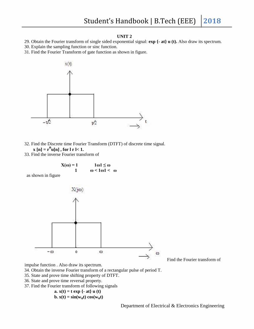
Student’s Handbook | B.Tech (EEE) 2018
UNIT 2 29. Obtain the Fourier transform of single sided exponential signal: exp - at u (t). Also draw its spectrum. 30. Explain the sampling function or sinc function.
31. Find the Fourier Transform of gate function as shown in figure.
32. Find the Discrete time Fourier Transform (DTFT) of discrete time signal.
x [n] = rnu[n] , for l r l< 1.
33. Find the inverse Fourier transform of
X(ω) = 1 1ω1 ≤ ω 1 ω < 1ω1 < ω
as shown in figure
Find the Fourier transform of impulse function . Also draw its spectrum. 34. Obtain the inverse Fourier transform of a rectangular pulse of period T.
35. State and prove time shifting property of DTFT.
36. State and prove time reversal property.
37. Find the Fourier transform of following signals a. x(t) = t exp - at u (t)
b. x(t) = sin(wot) cos(wot)
Department of Electrical & Electronics Engineering

Student’s Handbook | B.Tech (EEE) 2018
38. Find the Fourier transform of following discrete time signals
x[n] = a-n
u(-n) 1a1 > 1
x[n] = 1 1n1 ≤ N1
= 0 1n1 >N1
39. Discuss with example the convolution property of CTFT. Also give the physical significance of convolution property of CTFT. 40. Find the inverse of the discrete time Fourier transforms shown in figure.
41. Find the Fourier transform
x(t) = e-at
t ≥ 0
= 0 t < 0 42. Find the Fourier transform of signal
x(n) = A -M ≤ n ≤ M = 0 elsewhere.
43. Determine the output y (n) of a relaxed linear time invariant with impulse response: h (n) = an u(n), lal <
1 when the input is a unit steps sequence that is x(n) = u(n) .
44. Determine the Fourier transform of the function: y (n) = x(n)*h(n)
45. Compute the Fourier transform of the function:
a. x(n) = 2nu (- n)
b. x(n) = (1/4)n u(n + 4)
46. Determine the Fourier transform of a triangular function f(t) as shown in fig
47. Find the coefficient of complex exponential Fourier series for a half wave rectified sin wave, defined by
x (t) = A sin wot -To ≤ t ≤ To / 2
= 0 -To / 2 ≤ t ≤ To
Department of Electrical & Electronics Engineering

Student’s Handbook | B.Tech (EEE) 2018
With x(t) = x(t + To). 48. Determine the impulse response of h(n) for the system described by the second order difference equation: y(n) - 4y(n -1) + 4 y(n - 2) = x(n) - x(n - 1)
when y(-1) = x(- 2) = 0 49. Show that the Fourier transform of the convolution of two signals in the time domain can be given by the product of the Fourier transform of the individual signals in the frequency domain.
50. Determine the Fourier transform of the signal: x(t) = ½ [δ(t + 1) + δ(t - 1) + δ(t + 1/2) + δ(t - 1/2)] 51. What is the Dirichlets condition for the existence of Fourier transform. Determine the Fourier transform
of following signal: x(t) = e-at
u(t)
a)
b)
52. Determine the trigonometric Fourier series for following signals
Department of Electrical & Electronics Engineering

Student’s Handbook | B.Tech (EEE) 2018
Unit 3 1. Determine the impulse response of first order continuous time system. 2. A linear time LTI system is characterized by following difference equation
y[n] = a y[n - 1] + b x[n] for 0 < a <1
Find the magnitude and phase of the frequency response H (ejw
) of the system.
3. Discuss second order continuous time LTI system regarding magnitude and phase characteristics of its transfer function.
4. Determine the frequency response and magnitude response of the system given by y[n] + 1/2 y[n - 1] = x[n] – x[n - 1]
5. A causal LTI filter has the frequency response H( jw) shown in figure
Determine the filtered output y (t) if x (t) = ejt
6. Discuss magnitude and phase representation of frequency response of continuous time and discrete time LTI system. Define and discuss group delay.
7. consider a continuous ideal band pass filter whose frequency response is
H (jw) = 1 wc < w < 3wc
0 elsewhere
If h (t) is the impulse response, determine g (t) such that: h (t) =sin (wct)/πt g (t) 8. We have two discrete time LTI system with frequency responses:
H1(ejw
) = [1+(1/2)e- jw
] / [1+(1/4)e- jw
]
H2 (ejw
) = [1/2 + e -jw
] / [1+ (1/4) e- jw]
Show that | H1 (e jw
) | =| H2 (e jw
) |.
9. The input signal: x (t) = 4 sin c (2t) cos (4 πt ) is applied to a linear, time invariant system. Determine and plot the transfer function of the system H (f) such that its response will be y (t) = sin c (2t).
10. Consider a causal LTI system with frequency response: H(jw) = 1/ (jw + 2) for a particular input x(t). This system is observed to produce the output
y (t) = e- 2t
u (t) - e-3t
u(t) . Determine x(t).
00
11. When the impulse train x[n] = ∑ δ[n-4k] is the input of a particular LTI system k=-00
With frequency response H (ejw
), the output of the system is found to be y[n] = cos (5πn / 2) +( π/4)
Department of Electrical & Electronics Engineering

Student’s Handbook | B.Tech (EEE) 2018
UNIT_4
12. The differential equation of continuous time causal and stable LTI system is expressed as dy (t)/ dt + 5 y (t) = 2 x ( t)
Determine the step response of the system using Laplace transform.
13. State and prove “Sampling Theorem”. 14. What is “Aliasing effect”? find the nyquist rate and nyquist interval for the signal given
below x(t) = 1/2π cos (4000πt) cos (1000πt)
15. Find the response y(t) for the following system for the given input s(t) where : τ = RC
15. State and prove initial and final value theorem
16. Find the laplace transform of triangular pulse shown in figure
17. Determine the magnitude spectrum of the pulse signal shown in figure
18. Find the inverse laplace transform of: X(s) = 2 / (s + 4).(s - 1) for all possible signal convergence.
19. Use convolution theorem of laplace transform to find y(t) = x1(t) * x2(t) if
x1(t) = e-3t
u (t) & x2(t) = u(t-2)
Department of Electrical & Electronics Engineering

Student’s Handbook | B.Tech (EEE) 2018
20. For a system: H(s) = (s +2)/ (s2 + 5s + 4). Find the impulse response of the system function.
21. Find the Nyquist rate and Nyquist interval for each of the following signals. a) x(t) = 1 + cos (2000πt) + sin (4000 πt) b) x(t) = sin ( 4000 πt) / (πt)
22. Find the inverse Laplace transform of: G(s) = (10se-s
) / (s + 1) (s + 3).
23. Solve the differential equation d2x(t)/dt
2 + dx(t)/dt + 12x(t) = 0 for t<0 subject to initial condition x(0
-)
= 2 & dx(t)/dt at t =0- = -4.
24. Define the following terms
a. nyquist rate
b. sampling rate
c. Under, critical and over sampling.
25. What is aliasing phenomena? How can aliasing phenomena be determined? 26. Determined the Nyquist rate of following signal
x(t) = 1 + cos (2*103 πt) + sin (4*10
3 πt).
27. Determine the laplace transform and associated ROC and pole zero plot for each of the following function of time
a. x(t) = e-2t
u(t) + e-3t
u(t) b. x(t) = t e
-2t
c. x(t) = δ (3t) + u(t)
28. Explain the discrete time processing of continuous time signal? To achieve this give the block diagram of the system.
29. Find the nyquist rate and nyquist frequency for each of the following signals
a. x(t) = 4 sin c 2 (200 πt)
b. x(t) = -10 sin (40 πt) cos (300 πt).
30. Explain the following terms in brief
a. causality condition for LTI system
b. stability condition for LTI system
31. A signal has Laplace transform: X(s) = (s + a) / (s2 + 4s+5). Find the Laplace transform of following
signal y(t) = x(2t-1)u(2t-1).
32. Consider a frequency domain transfer H(s) of a system is given below
H(s) = (s + a) / (s + a) 2 + wo
2. Re(s) > - a.
Find h(t), the impulse response. 33. What is the spectrum of instantaneously sampled signal? discuss two different spectrum for it. 34. Determine the condition as the sampling interval T so that the signal
x(t) = cos (2 πt) sin(πt)/ πt + 3 sin (6 πt) sin(2 πt)/ πt is uniquely represented by its samples.
35. A continuous time signal x(t) is applied to the input of LTI system
where: x(t) = e- at
u(t) for a>0 & h(t) =u(t) . Evaluate the output y
Department of Electrical & Electronics Engineering

Student’s Handbook | B.Tech (EEE) 2018
UNIT-5 1.Define Z transform .2.Define ROC. 3. Find Z transform of x(n)=1,2,3,4
4. State the convolution property of Z transform.
5. What is z-transform of (n-m)?
6. State initial value theorem.
7. List the methods of obtaining inverse Z transform.
8. Obtain the inverse z transform of X(z)=1/z-a,|z|>|a|
9.Give the relationship between z-transform and Fourier transform. 10. Determine the inverse z transform of the following function x(z)=1 / (1 + z -1) (1 –z -1 )2 ROC : |Z>1| 11. Find the z-transform of x(n) = an u(n) and for unit impulse signal
Department of Electrical & Electronics Engineering