build your own mortising machine -...
TRANSCRIPT
From ShopNotes magazinewww.ShopNotes.com
page 1 of 10 ©2006 August Home Publishing CompanyAll rights reserved
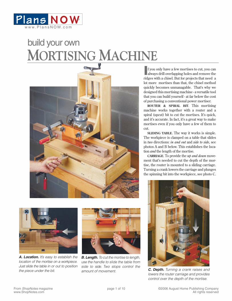
C. Depth. Turning a crank raises and lowers the router carriage and provides control over the depth of the mortise.
B. Length. To cut the mortise to length, use the handle to slide the table from side to side. Two stops control the amount of movement.
A. Location. It’s easy to establish the location of the mortise on a workpiece. Just slide the table in or out to position the piece under the bit.
If you only have a few mortises to cut, you can always drill overlapping holes and remove the
ridges with a chisel. But for projects that need a lot more mortises than that, the chisel method quickly becomes unmanagable. That's why we designed this mortising machine - a versatile tool that you can build yourself - at far below the cost of purchasing a conventional power mortiser.
ROUTER & SPIRAL BIT. This mortising machine works together with a router and a spiral (upcut) bit to cut the mortises. It’s quick, and it’s accurate. In fact, it’s a great way to make mortises even if you only have a few of them to cut.
SLIDING TABLE. The way it works is simple. The workpiece is clamped on a table that slides in two directions: in and out and side to side, see photos A and B below. This establishes the loca-tion and the length of the mortise.
CARRIAGE. To provide the up and down move-ment that’s needed to cut the depth of the mor-tise, the router is mounted to a sliding carriage. Turning a crank lowers the carriage and plunges the spinning bit into the workpiece, see photo C.
Plans N O Ww w w . P l a n s N O W. c o m
®
build your own
MORTISING MACHINE
From ShopNotes magazinewww.ShopNotes.com
page 2 of 10 ©2006 August Home Publishing CompanyAll rights reserved
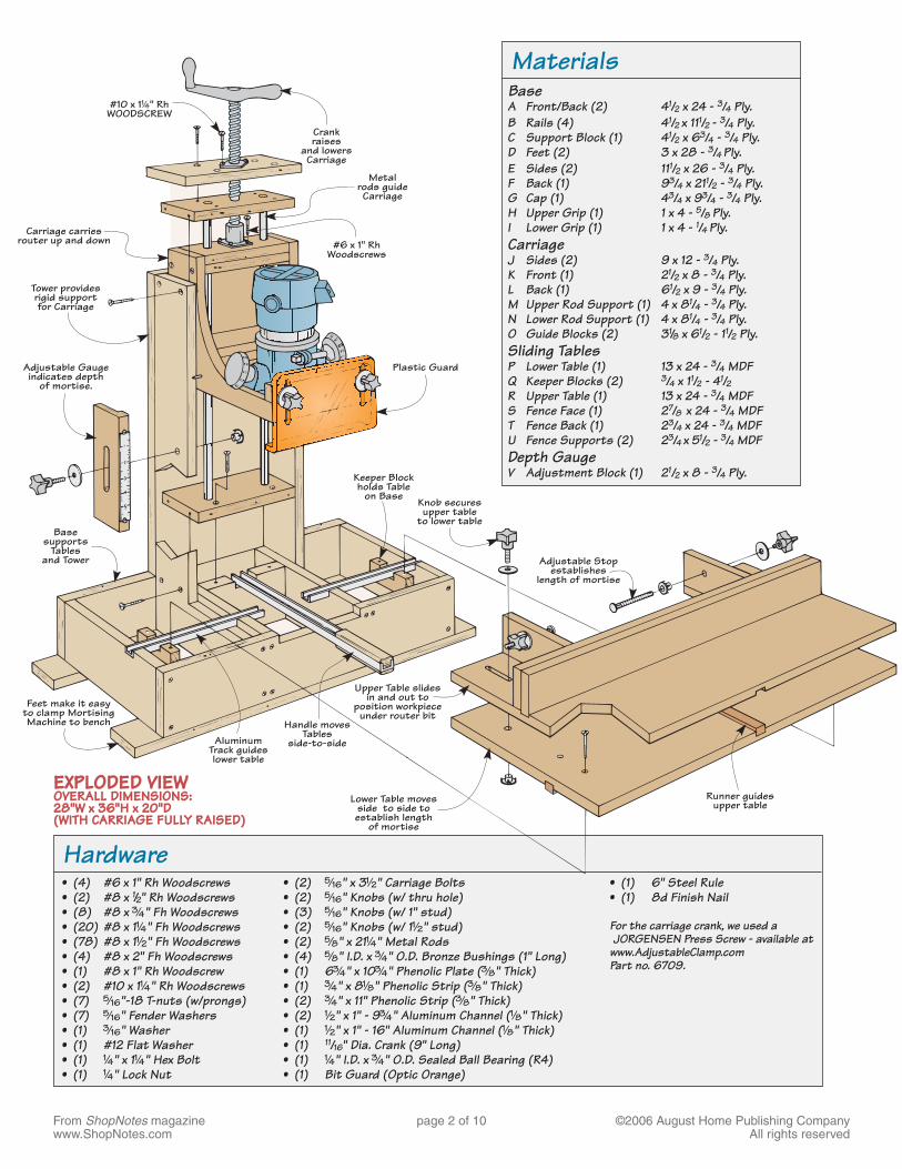
Hardware • (4) #6 x 1" Rh Woodscrews • (2) #8 x 1/2" Rh Woodscrews • (8) #8 x #/4" Fh Woodscrews • (20) #8 x 1!/4" Fh Woodscrews • (78) #8 x 1!/2" Fh Woodscrews • (4) #8 x 2" Fh Woodscrews • (1) #8 x 1" Rh Woodscrew • (2) #10 x 1!/4" Rh Woodscrews • (7) %/16"-18 T-nuts (w/prongs) • (7) %/16" Fender Washers • (1) #/16" Washer • (1) #12 Flat Washer • (1) !/4" x 1!/4" Hex Bolt • (1) !/4" Lock Nut
MaterialsBaseA Front/Back (2) 41/2 x 24 - 3/4 Ply.B Rails (4) 41/2 x 111/2 - 3/4 Ply.C Support Block (1) 41/2 x 63/4 - 3/4 Ply.D Feet (2) 3 x 28 - 3/4 Ply.E Sides (2) 111/2 x 26 - 3/4 Ply.F Back (1) 93/4 x 211/2 - 3/4 Ply.G Cap (1) 43/4 x 93/4 - 3/4 Ply.H Upper Grip (1) 1 x 4 - 5/8 Ply.I Lower Grip (1) 1 x 4 - 1/4 Ply.CarriageJ Sides (2) 9 x 12 - 3/4 Ply.K Front (1) 21/2 x 8 - 3/4 Ply.L Back (1) 61/2 x 9 - 3/4 Ply.M Upper Rod Support (1) 4 x 81/4 - 3/4 Ply.N Lower Rod Support (1) 4 x 81/4 - 3/4 Ply.O Guide Blocks (2) 31/8 x 61/2 - 11/2 Ply.Sliding TablesP Lower Table (1) 13 x 24 - 3/4 MDFQ Keeper Blocks (2) 3/4 x 11/2 - 41/2 R Upper Table (1) 13 x 24 - 3/4 MDFS Fence Face (1) 27/8 x 24 - 3/4 MDFT Fence Back (1) 23/4 x 24 - 3/4 MDFU Fence Supports (2) 23/4 x 51/2 - 3/4 MDFDepth GaugeV Adjustment Block (1) 21/2 x 8 - 3/4 Ply.
• (1) 6" Steel Rule • (1) 8d Finish Nail For the carriage crank, we used a
JORGENSEN Press Screw - available at www.AdjustableClamp.com Part no. 6709.
• (2) %/16" x 3!/2" Carriage Bolts • (2) %/16" Knobs (w/ thru hole) • (3) %/16" Knobs (w/ 1" stud) • (2) %/16" Knobs (w/ 1!/2" stud) • (2) %/8" x 21!/4" Metal Rods • (4) %/8" I.D. x #/4" O.D. Bronze Bushings (1" Long) • (1) 6#/4" x 10#/4" Phenolic Plate (#/8" Thick) • (1) #/4" x 8!/8" Phenolic Strip (#/8" Thick) • (2) #/4" x 11" Phenolic Strip (#/8" Thick) • (2) !/2" x 1" - 9#/4" Aluminum Channel (!/8" Thick) • (1) !/2" x 1" - 16" Aluminum Channel (!/8" Thick) • (1) 11/16'' Dia. Crank (9" Long) • (1) !/4" I.D. x #/4" O.D. Sealed Ball Bearing (R4) • (1) Bit Guard (Optic Orange)
From ShopNotes magazinewww.ShopNotes.com
page 3 of 10 ©2006 August Home Publishing CompanyAll rights reserved
Base ————————————————————————————————————————
21
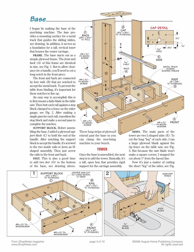
I began by making the base of the mortising machine. The base pro-vides a mounting surface for a metal track that guides the sliding tables, see drawing. In addition, it serves as a foundation for a tall, vertical tower that houses the router carriage.
FRAME. The base starts out as a simple plywood frame. The front and back (A) of this frame are identical in size, see Fig. 1. But to allow clear-ance for a handle, you’ll need to cut a long notch in the front piece.
The front and back are connected by four rails (B) that are notched to accept the metal track. To prevent the table from binding, it’s important for these notches to line up.
An easy way to accomplish this is to first mount a dado blade in the table saw. Then butt each rail against a stop block clamped to a fence on the miter gauge, see Fig. 2. After making a single pass for each rail, reposition the stop block and make a second pass to complete the notches.
SUPPORT BLOCK. Before assem-bling the base, I added a plywood sup-port block (C) to hold the end of the handle. After notching the support block to accept the handle, it’s screwed to the two inside rails to form an H-shaped assembly. Then just screw the rails to the front and back.
FEET. This is also a good time to add two feet (D) to the bottom of the base, see drawing above.
These long strips of plywood extend past the base so you can clamp the mortising machine to your bench.
TOWEROnce the base is assembled, the next step is to add the tower. Basically, it’s a tall, open box that provides rigid support for the carriage assembly.
SIDES. The main parts of the tower are two L-shaped sides (E). To cut the long “leg” of each side, I ran a large plywood blank against the rip fence on the table saw, see Fig. 3. But because the saw blade won’t make a square corner, I stopped the cut about 1'' from the layout line.
Now it’s just a matter of cutting the short “leg” of the sides, see Fig.
From ShopNotes magazinewww.ShopNotes.com
page 4 of 10 ©2006 August Home Publishing CompanyAll rights reserved
5
3
4
6a.
a.b.
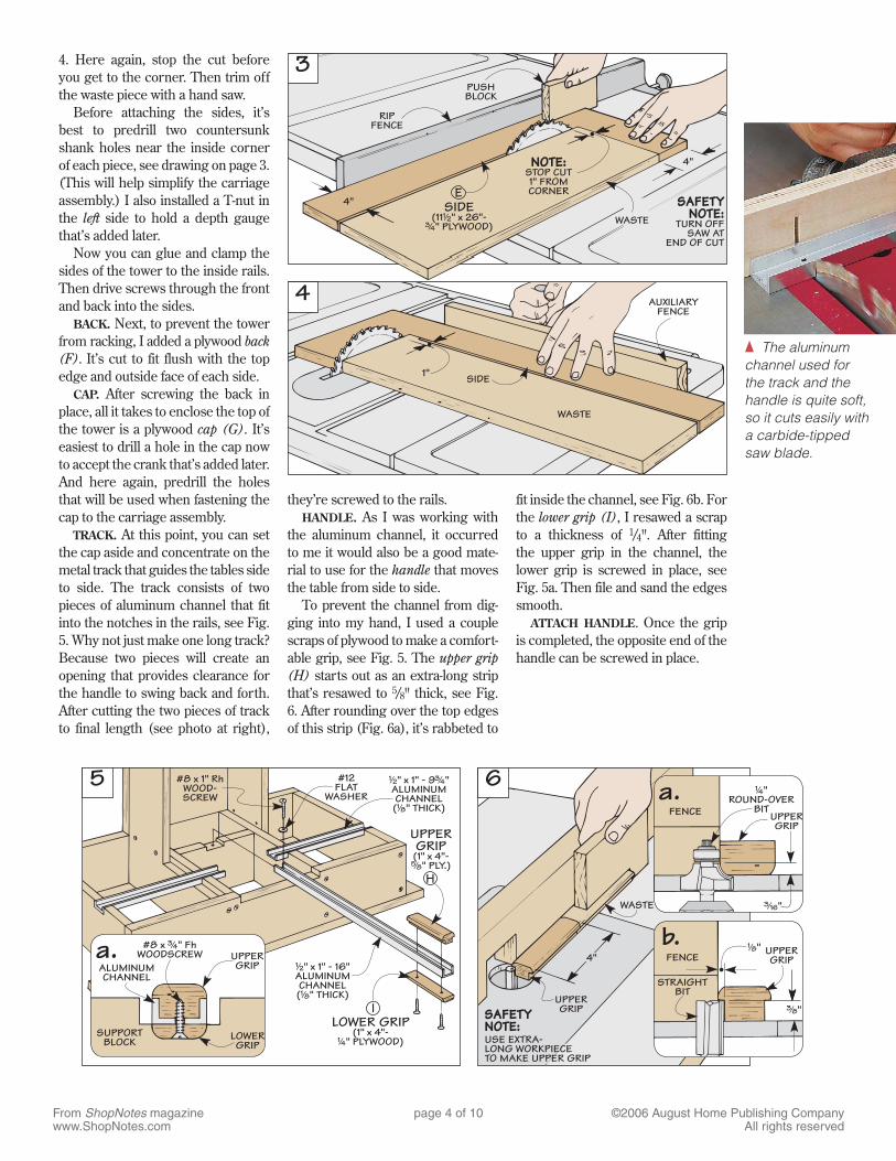
4. Here again, stop the cut before you get to the corner. Then trim off the waste piece with a hand saw.
Before attaching the sides, it’s best to predrill two countersunk shank holes near the inside corner of each piece, see drawing on page 3. (This will help simplify the carriage assembly.) I also installed a T-nut in the left side to hold a depth gauge that’s added later.
Now you can glue and clamp the sides of the tower to the inside rails. Then drive screws through the front and back into the sides.
BACK. Next, to prevent the tower from racking, I added a plywood back (F). It’s cut to fit flush with the top edge and outside face of each side.
CAP. After screwing the back in place, all it takes to enclose the top of the tower is a plywood cap (G). It’s easiest to drill a hole in the cap now to accept the crank that’s added later. And here again, predrill the holes that will be used when fastening the cap to the carriage assembly.
TRACK. At this point, you can set the cap aside and concentrate on the metal track that guides the tables side to side. The track consists of two pieces of aluminum channel that fit into the notches in the rails, see Fig. 5. Why not just make one long track? Because two pieces will create an opening that provides clearance for the handle to swing back and forth. After cutting the two pieces of track to final length (see photo at right),
they’re screwed to the rails. HANDLE. As I was working with
the aluminum channel, it occurred to me it would also be a good mate-rial to use for the handle that moves the table from side to side.
To prevent the channel from dig-ging into my hand, I used a couple scraps of plywood to make a comfort-able grip, see Fig. 5. The upper grip (H) starts out as an extra-long strip that’s resawed to 5/8'' thick, see Fig. 6. After rounding over the top edges of this strip (Fig. 6a), it’s rabbeted to
fit inside the channel, see Fig. 6b. For the lower grip (I), I resawed a scrap to a thickness of 1/4''. After fitting the upper grip in the channel, the lower grip is screwed in place, see Fig. 5a. Then file and sand the edges smooth.
ATTACH HANDLE. Once the grip is completed, the opposite end of the handle can be screwed in place.
{ The aluminum channel used for the track and the handle is quite soft, so it cuts easily with a carbide-tipped saw blade.
From ShopNotes magazinewww.ShopNotes.com
page 5 of 10 ©2006 August Home Publishing CompanyAll rights reserved
8
Carriage Assembly ——————————————————————————
9
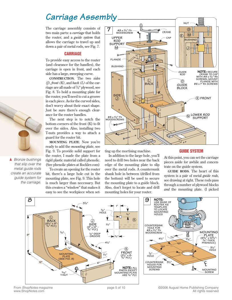
ting up the mortising machine.In addition to the large hole, you’ll
need to drill two holes near the back edge of the mounting plate to slip over the metal rods. A countersunk shank hole in between (drilled from the bottom) will be used to secure the mounting plate to a guide block. Also, don’t forget to locate and drill mounting holes for your router.
GUIDE SYSTEMAt this point, you can set the carriage pieces aside for awhile and concen-trate on the guide system.
GUIDE RODS. The heart of this system is a pair of metal guide rods, see drawing at right. These rods pass through a number of plywood blocks and the mounting plate. (I picked
a.
7The carriage assembly consists of two main parts: a carriage that holds the router, and a guide system that allows the carriage to travel up and down a pair of metal rods, see Fig. 7.
CARRIAGETo provide easy access to the router (and clearance for the handles), the carriage is open in front, and each side has a large, sweeping curve.
CONSTRUCTION. The two sides (J), front (K), and back (L) of the car-riage are all made of 3/4" plywood, see Fig. 8. To hold a mounting plate for the router, you’ll need to cut a groove in each piece. As for the curved sides, don’t worry about their exact shape. Just be sure there’s enough clear-ance for the router handles.
The next step is to notch the bottom corners of the front (K) to fit over the sides. Also, installing two T-nuts provides a way to attach a guard for the router bit.
MOUNTING PLATE. Now you’re ready to add the mounting plate, see Fig. 9. To provide solid support for the router, I made the plate from a rigid plastic material called phenolic. (See phenolic plates at Rockler.com)
To create an opening for the router bit, there’s a large hole cut in the mounting plate, see Fig. 9. This hole is much larger than necessary. But this creates a “window” that makes it easy to see the workpiece when set-
{ Bronze bushings that slip over the metal guide rods
create an accurate guide system for
the carriage.
From ShopNotes magazinewww.ShopNotes.com
page 6 of 10 ©2006 August Home Publishing CompanyAll rights reserved
10
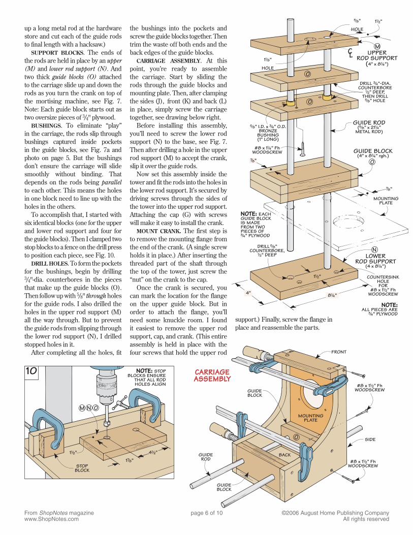
up a long metal rod at the hardware store and cut each of the guide rods to final length with a hacksaw.)
SUPPORT BLOCKS. The ends of the rods are held in place by an upper (M) and lower rod support (N). And two thick guide blocks (O) attached to the carriage slide up and down the rods as you turn the crank on top of the mortising machine, see Fig. 7. Note: Each guide block starts out as two oversize pieces of 3/4" plywood.
BUSHINGS. To eliminate “play” in the carriage, the rods slip through bushings captured inside pockets in the guide blocks, see Fig. 7a and photo on page 5. But the bushings don’t ensure the carriage will slide smoothly without binding. That depends on the rods being parallel to each other. This means the holes in one block need to line up with the holes in the others.
To accomplish that, I started with six identical blocks (one for the upper and lower rod support and four for the guide blocks). Then I clamped two stop blocks to a fence on the drill press to position each piece, see Fig. 10.
DRILL HOLES. To form the pockets for the bushings, begin by drilling 3/4"-dia. counterbores in the pieces that make up the guide blocks (O). Then follow up with 5/8" through holes for the guide rods. I also drilled the holes in the upper rod support (M) all the way through. But to prevent the guide rods from slipping through the lower rod support (N), I drilled stopped holes in it.
After completing all the holes, fit
the bushings into the pockets and screw the guide blocks together. Then trim the waste off both ends and the back edges of the guide blocks.
CARRIAGE ASSEMBLY. At this point, you’re ready to assemble the carriage. Start by sliding the rods through the guide blocks and mounting plate. Then, after clamping the sides (J), front (K) and back (L) in place, simply screw the carriage together, see drawing below right.
Before installing this assembly, you’ll need to screw the lower rod support (N) to the base, see Fig. 7. Then after drilling a hole in the upper rod support (M) to accept the crank, slip it over the guide rods.
Now set this assembly inside the tower and fit the rods into the holes in the lower rod support. It’s secured by driving screws through the sides of the tower into the upper rod support. Attaching the cap (G) with screws will make it easy to install the crank.
MOUNT CRANK. The first step is to remove the mounting flange from the end of the crank. (A single screw holds it in place.) After inserting the threaded part of the shaft through the top of the tower, just screw the “nut” on the crank to the cap.
Once the crank is secured, you can mark the location for the flange on the upper guide block. But in order to attach the flange, you’ll need some knuckle room. I found it easiest to remove the upper rod support, cap, and crank. (This entire assembly is held in place with the four screws that hold the upper rod
1!/2"
NOTE: EACHGUIDE BLOCKIS MADEFROM TWOPIECES OF
" PLYWOOD#/4
CL
4"8 "!/4
COUNTERSINKHOLEFOR
#8 x 1 " FhWOODSCREW
!/2
DRILL "COUNTERBORE,
" DEEP
%/8
!/2 LOWERROD SUPPORT
(4 x 8 ")!/4
N
#8 x 1 " FhWOODSCREW
!/4
&/8"
%/8"
HOLE
&/8" O
O
O
GUIDE BLOCK(4" x 8 " rgh.)!/4
MOUNTINGPLATE
NOTE:ALL PIECES ARE
" PLYWOOD#/4
1 "!/2
" I.D. x " O.D.BRONZE
BUSHING(1" LONG)
%/8 #/4
1 "
HOLE
!/8
MUPPER
ROD SUPPORT(4" x 8 ")!/4
DRILL "-DIA.COUNTERBORE
" DEEP,THEN DRILL
" HOLE
#/4
!/2
%/8
GUIDE ROD( " x 21 "
METAL ROD)%/8 !/4
support.) Finally, screw the flange in place and reassemble the parts.
From ShopNotes magazinewww.ShopNotes.com
page 7 of 10 ©2006 August Home Publishing CompanyAll rights reserved
Sliding Tables ———————————————————————————————11
13
a.
a.
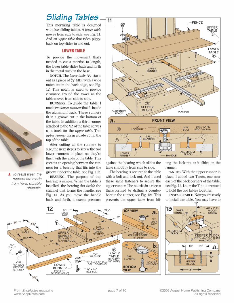
against the bearing which slides the table smoothly from side to side.
The bearing is secured to the table with a bolt and lock nut. And I used these same fasteners to secure the upper runner. The nut sits in a recess that’s formed by drilling a counter-bore in the runner, see Fig. 12a. This prevents the upper table from hit-
ting the lock nut as it slides on the runner.
T-NUTS. With the upper runner in place, I added two T-nuts, one near each of the back corners of the table, see Fig. 12. Later, the T-nuts are used to hold the two tables together.
INSTALL TABLE. Now you’re ready to install the table. You may have to
12a.
b.
{ To resist wear, the runners are made
from hard, durable phenolic.
This mortising table is designed with two sliding tables. A lower table moves from side to side, see Fig. 11. And an upper table that rides piggy-back on top slides in and out.
LOWER TABLETo provide the movement that’s needed to cut a mortise to length, the lower table slides back and forth in the metal track in the base.
NOTCH. The lower table (P) starts out as a piece of 3/4" MDF with a wide notch cut in the back edge, see Fig. 12. This notch is sized to provide clearance around the tower as the table moves from side to side.
RUNNERS. To guide the table, I made two lower runners that fit inside the aluminum track. These runners fit in a groove cut in the bottom of the table. In addition, a third runner attached to the top of the table serves as a track for the upper table. This upper runner fits in a dado cut in the top of the table.
After cutting all the runners to size, the next step is to screw the two lower runners in place so they’re flush with the ends of the table. This creates an opening between the run-ners for a bearing that fits into the groove under the table, see Fig. 12b.
BEARING. The purpose of this bearing is simple. When the table is installed, the bearing fits inside the channel that forms the handle, see Fig.11a. As you move the handle back and forth, it exerts pressure
From ShopNotes magazinewww.ShopNotes.com
page 8 of 10 ©2006 August Home Publishing CompanyAll rights reserved
14
15a.
b.a.
jockey it around a bit to fit the bearing down in the handle and to get the runners to slip into the track.
KEEPER BLOCKS. With the table in place, I added two hardwood keeper blocks (Q), see Figs. 13 and 13a. These blocks prevent the table from lifting up when working with long pieces that hang over the base. To do this, the blocks are notched to fit around the track and screwed to the table.
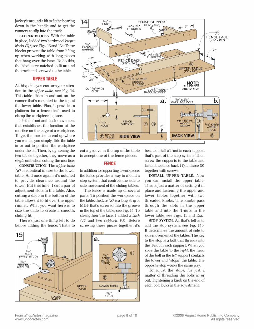
UPPER TABLEAt this point, you can turn your atten-tion to the upper table, see Fig. 14. This table slides in and out on the runner that’s mounted to the top of the lower table. Plus, it provides a platform for a fence that’s used to clamp the workpiece in place.
It’s this front and back movement that establishes the location of the mortise on the edge of a workpiece. To get the mortise to end up where you want it, you simply slide the table in or out to position the workpiece under the bit. Then, by tightening the two tables together, they move as a single unit when cutting the mortise.
CONSTRUCTION. The upper table (R) is identical in size to the lower table. And once again, it’s notched to provide clearance around the tower. But this time, I cut a pair of adjustment slots in the table. Also, cutting a dado in the bottom of the table allows it to fit over the upper runner. What you want here is to size the dado to create a smooth, sliding fit.
There’s just one thing left to do before adding the fence. That’s to
cut a groove in the top of the table to accept one of the fence pieces.
FENCEIn addition to supporting a workpiece, the fence provides a way to mount a stop system that controls the side to side movement of the sliding tables.
The fence is made up of several parts. To position the workpiece on the table, the face (S) is a long strip of MDF that’s screwed into the groove in the top of the table, see Fig. 14. To strengthen the face, I added a back (T) and two supports (U). Before screwing these pieces together, it’s
best to install a T-nut in each support that’s part of the stop system. Then screw the supports to the table and fasten the fence back (T) and face (S) together with screws.
INSTALL UPPER TABLE. Now you can install the upper table. This is just a matter of setting it in place and fastening the upper and lower tables together with two threaded knobs. The knobs pass through the slots in the upper table and into the T-nuts in the lower table, see Figs. 15 and 15a.
STOP SYSTEM. All that’s left is to add the stop system, see Fig. 14b. It determines the amount of side to side movement of the tables. The key to the stop is a bolt that threads into the T-nut in each support. When you slide the table to the right, the head of the bolt in the left support contacts the tower and “stops” the table. The opposite stop works the same way.
To adjust the stops, it’s just a matter of threading the bolts in or out. Tightening a knob on the end of each bolt locks in the adjustment.
From ShopNotes magazinewww.ShopNotes.com
page 9 of 10 ©2006 August Home Publishing CompanyAll rights reserved
Depth Gauge ———————————————————————————————
Router Bit Guard ———————————————————————————
17
16a.
a.
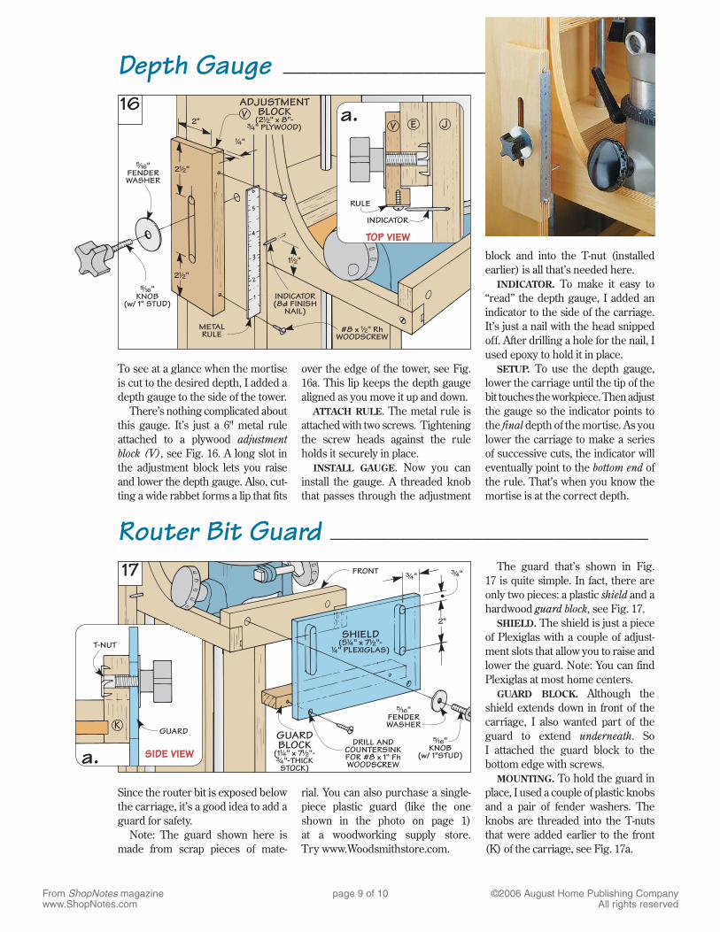
To see at a glance when the mortise is cut to the desired depth, I added a depth gauge to the side of the tower.
There’s nothing complicated about this gauge. It’s just a 6" metal rule attached to a plywood adjustment block (V), see Fig. 16. A long slot in the adjustment block lets you raise and lower the depth gauge. Also, cut-ting a wide rabbet forms a lip that fits
over the edge of the tower, see Fig. 16a. This lip keeps the depth gauge aligned as you move it up and down.
ATTACH RULE. The metal rule is attached with two screws. Tightening the screw heads against the rule holds it securely in place.
INSTALL GAUGE. Now you can install the gauge. A threaded knob that passes through the adjustment
block and into the T-nut (installed earlier) is all that’s needed here.
INDICATOR. To make it easy to “read” the depth gauge, I added an indicator to the side of the carriage. It’s just a nail with the head snipped off. After drilling a hole for the nail, I used epoxy to hold it in place.
SETUP. To use the depth gauge, lower the carriage until the tip of the bit touches the workpiece. Then adjust the gauge so the indicator points to the final depth of the mortise. As you lower the carriage to make a series of successive cuts, the indicator will eventually point to the bottom end of the rule. That’s when you know the mortise is at the correct depth.
Since the router bit is exposed below the carriage, it’s a good idea to add a guard for safety.
Note: The guard shown here is made from scrap pieces of mate-
rial. You can also purchase a single-piece plastic guard (like the one shown in the photo on page 1) at a woodworking supply store. Try www.Woodsmithstore.com.
The guard that’s shown in Fig. 17 is quite simple. In fact, there are only two pieces: a plastic shield and a hardwood guard block, see Fig. 17.
SHIELD. The shield is just a piece of Plexiglas with a couple of adjust-ment slots that allow you to raise and lower the guard. Note: You can find Plexiglas at most home centers.
GUARD BLOCK. Although the shield extends down in front of the carriage, I also wanted part of the guard to extend underneath. So I attached the guard block to the bottom edge with screws.
MOUNTING. To hold the guard in place, I used a couple of plastic knobs and a pair of fender washers. The knobs are threaded into the T-nuts that were added earlier to the front (K) of the carriage, see Fig. 17a.
From ShopNotes magazinewww.ShopNotes.com
page 10 of 10 ©2006 August Home Publishing CompanyAll rights reserved
Setup & Use ————————————————————————————————
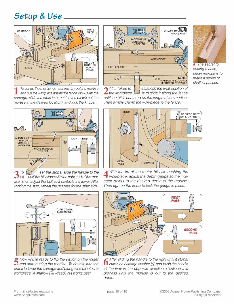
1 To set up the mortising machine, lay out the mortise and butt the workpiece against the fence. Now lower the
carriage, slide the table in or out (so the bit will cut the mortise at the desired location), and lock the knobs.
2 All it takes to establish the final position of the workpiece is to slide it along the fence
until the bit is centered on the length of the mortise. Then simply clamp the workpiece to the fence.
4 With the tip of the router bit still touching the workpiece, adjust the depth gauge so the indi-
cator points to the desired depth of the mortise. Then tighten the knob to lock the gauge in place.
6 After sliding the handle to the right until it stops, lower the carriage another 1/8" and push the handle
all the way in the opposite direction. Continue this process until the mortise is cut to the desired depth.
5 Now you’re ready to flip the switch on the router and start cutting the mortise. To do this, turn the
crank to lower the carriage and plunge the bit into the workpiece. A shallow (1/8''-deep) cut works best.
{ The secret to cutting a crisp, clean mortise is to make a series of shallow passes.
3 To set the stops, slide the handle to the left until the bit aligns with the right end of the mor-
tise. Then adjust the bolt so it contacts the tower. After locking the stop, repeat the process for the other side.

MORE WOODWORKING PLANS
One of the most important ingredients of any successful woodworking project is having accurate proven plans to work by like this one.
But doing your own plans can also be a hassle especially if you don't like to draw or don't have the time, tools or software to do your own. And after all, you want to get to the good stuff “making sawdust” as soon as possible, don’t you! Why not check out this woodworker’s ideal resource that contains all the woodworking plans you will ever want, for any project you can dream about, all in one place.
Crispin Thomas (Sawdust Addict)