building information modeling (bim) and design for ......1. explore bim tools and software platforms...
TRANSCRIPT

Building Information Modeling (BIM) and Design for Manufacturing and Assembly (DfMA)
for Mass Timber Construction
November 8, 2018
Created by:
Sheryl Staub-French, PhD, PEng Erik A. Poirier, PhD
Francisco Calderon, MASc Imen Chikhi, M. Arch.Puyan Zadeh, Dr.-Ing
Divyarajsinh Chudasma Shitian Huang
BIM TOPiCS Research LabUniversity of British Columbia
bimtopics.civil.ubc.ca

Cover photos courtesy of Lucas Epp/StructureCraft

i
Table of Contents
Executive Summary .............................................................................................................. iii
Background .................................................................................................................................. iii
Research Objectives and Methodology .......................................................................................... iii
Summary of Findings ..................................................................................................................... iv
Benefits of BIM and DfMA .............................................................................................................. v
Challenges with BIM and DfMA ..................................................................................................... vi
Industry-Focused Recommendations ............................................................................................ vii
Project-Focused Recommendations ............................................................................................. viii
Report Summary ............................................................................................................................ x
Glossary ............................................................................................................................... xi
Introduction .......................................................................................................................... 1
Background: BIM and DfMA in the Context of Mass Timber Construction ............................... 5
Core Concepts ................................................................................................................................5 Building Information Modeling ............................................................................................................................ 5 Design for Manufacture and Assembly .............................................................................................................. 10 BIM and DfMA .................................................................................................................................................... 14
Other Relevant Initiatives............................................................................................................. 17 Lean and DfMA of Mass Timber ......................................................................................................................... 17 BIM Platforms and Product Libraries for Mass Timber ...................................................................................... 18
BIM and DfMA for Other Domains: The Steel Construction Sector ................................................. 20
Conclusions ................................................................................................................................. 25
Findings: BIM and DfMA in Mass Timber Construction ......................................................... 26
DfMA and Organizing BIM Projects ............................................................................................... 26 Types of BIMs and Modeling Environments ...................................................................................................... 26 Project Organization .......................................................................................................................................... 29 Roles and Responsibilities .................................................................................................................................. 32 BIM Execution Planning ..................................................................................................................................... 32
Uses of BIM ................................................................................................................................. 33 Visualization ....................................................................................................................................................... 33 Structural Analysis .............................................................................................................................................. 34 BIM Coordination and Clash Detection .............................................................................................................. 36 Constructability Review ..................................................................................................................................... 38 Generation of Project Documentation ............................................................................................................... 39 Quantity Takeoff to Support Cost Estimating .................................................................................................... 41 Planning Construction Methods......................................................................................................................... 42 Transportation and Delivery Logistics ................................................................................................................ 43 4D Scheduling & Progress Tracking .................................................................................................................... 45 Lifting and Center of Gravity Analysis ................................................................................................................ 46 Digital Fabrication .............................................................................................................................................. 46

ii
BIM Workflows ............................................................................................................................ 47 Conceptual Design ............................................................................................................................................. 50 Design Development .......................................................................................................................................... 50 Construction Documentation ............................................................................................................................. 51 Detailing ............................................................................................................................................................. 52 Manufacturing.................................................................................................................................................... 52 Assembly ............................................................................................................................................................ 53
BIM Tools and Information Exchange ........................................................................................... 53 Common Design Tools ....................................................................................................................................... 53 Common Manufacturing Tools .......................................................................................................................... 57 Information Exchange and Interoperability ....................................................................................................... 60
Conclusions ................................................................................................................................. 63
Findings: Industry Readiness Survey ..................................................................................... 64 BIM Adoption ..................................................................................................................................................... 65 Mass Timber Construction ................................................................................................................................. 69 Adoption of DfMA Principals .............................................................................................................................. 70 Conclusions ........................................................................................................................................................ 71
Benefits, Challenges and Recommendations ........................................................................ 72
Benefits of BIM and DfMA ............................................................................................................ 72
Challenges with BIM and DfMA .................................................................................................... 73
Recommendations ....................................................................................................................... 74 Industry-Focused ................................................................................................................................................ 74 Project-Focused ................................................................................................................................................. 75
Conclusions ......................................................................................................................... 77
Acknowledgements ............................................................................................................. 78
References........................................................................................................................... 79
Appendix: Survey Questionnaire .......................................................................................... 83

iii
Executive Summary
Background The increasing appetite for innovation, performance and sustainability in the Canadian Architecture, Engineering, Construction, Owners and Operators (AECOO) community is leading to the development and deployment of approaches, be they tools, technologies, practices, etc., that are causing a significant shift in the delivery and management of built assets. When deployed correctly, these approaches promise significant benefits. On the other hand, their deployment is fraught with challenges. The study presented in this report investigates the synergies between three such approaches: Building Information Modeling (BIM), Design for Manufacturing and Assembly (DfMA) and mass timber construction. The objective is to help inform the way forward and support the deployment of these approaches within the British Columbia (BC) AECOO community. The study was initiated by BC Forestry Innovation Investment (FII) in the context of the Wood First Funding Program. The overarching goal of the program is to position British Columbia as a leader in using innovative forest products and building systems – successful deployment of these approaches, it is believed, can help achieve this goal. Synergies between these approaches have been investigated in the past. For example, BIM and DfMA has been receiving increased attention over the past decade, being the subject of government programs in Singapore and the United Kingdom and multiple research projects around the globe. From these initiatives, several lessons learned and recommendations have been put forth. Furthermore, the benefits of these approaches are becoming clearer. For instance, the Building Construction Authority (BCA) in Singapore has found that BIM for DfMA provides a number of benefits across an asset’s lifecycle Research Objectives and Methodology The study laid out in this report aims to build on the lessons learned from around the globe and in BC to promote and facilitate the deployment of BIM and DfMA in the context of mass timber construction. The study’s objectives were to:
1. Explore BIM tools and software platforms that support collaboration and optimization of design solutions as well as enable seamless exchange of information in the context of DfMA of mass-timber solutions.
2. Investigate the potential impact of the use of BIM tools and software platforms on project and team outcomes in the context of mass-timber construction.
3. Investigate how the modeling process can be streamlined to minimize waste and optimize the DfMA process in the context of mass-timber construction.
4. Investigate the readiness of manufacturers and installer/assemblers to supply BIM data for products and systems.
5. Propose recommendations to position the supply chain to design, manufacture and assemble mass-timber structures.
6. Propose recommendations that identify future training requirements for BIM enabled DfMA in the context of mass-timber construction.
iv
The findings of the study are based on a mixed-method approach to data collection and analysis, including an extensive review of the literature, interviews with a number of key stakeholders in BC, a review of existing tools and technologies as well as a survey of industry practitioners. The literature review was conducted specifically looking into research that investigated BIM and DfMA in the context of mass timber construction. Interviews were conducted with experts and key members of the mass timber industry. Several case studies were analyzed to extract lessons learned and best practices. Finally, a survey targeting key members of the mass timber industry was conducted. Summary of Findings The research presented in this report has helped to better uncover the synergies between BIM, DfMA and their application in the context of mass timber construction. Notably, it is expected that greater emphasis on these approaches will help to eliminate some of the barriers that are keeping mass timber construction from increasing its market share and allow mass timber projects to fully explore the advantages of BIM and DfMA. Indeed, it was observed that mass timber projects carry a higher cost due to additional documentation and procedures required by Authorities Having Jurisdiction (AHJ), and unfamiliarity with the systems, which are pushing owners and developers away from the use of mass timber. With high-rise wood construction being relatively uncommon, unfamiliarity can result in increased premiums due to higher perceived risks. In cases where BIM was employed, contractors were able to clearly visualize their scope of work and working conditions, resulting in more competitive bids. In fact, case studies and interviews showed that contractors working in mass timber projects usually found themselves in ideal conditions that exceeded the ones encountered on projects with other types of constructive systems. It was also noted that BIM can also help to facilitate approvals and regulatory procedures as it allows the AHJ to more clearly visualize the proposed solutions. The advantages of mass timber construction include a high precision of the as-built conditions, compressed project timelines, and an opportunity for high amounts of offsite manufacturing. BIM can potentially support all the aspects of mass timber projects, including offsite manufacture where fabrication level models can be leveraged to detail all timber elements and automate the generation of CNC codes. Additionally, when employing BIM in a mass timber project, the high level of precision that can be achieved during the installation of the structure leads to a scenario where the as-built conditions can closely match the information model(s) produced during the design stage. This eliminates a barrier that is keeping the industry from exploring higher levels of offsite manufacture, which could allow different subcontractors to achieve higher levels of efficiency and lower costs. Finally, BIM-VDC allows practitioners to simulate installation and construction sequences and different construction methods. This allows project teams to optimize the construction process, reducing the required number of workers onsite, improving safety, and further guaranteeing time savings. Mass timber construction can also benefit from the more general benefits of BIM, including higher productivity, reduced amount of change orders and issues during construction, higher quality, and reduced waste. Additionally, BIM can help to (1) bring down barriers that are keeping mass timber products from being further implemented in the local construction industry and (2)

v
allow project team members to fully explore the advantages of mass timber construction. The findings of this research project provide a series of recommendations that are meant to provide the local industry with the necessary information to successfully implement this technology and take steps towards a more widespread and comprehensive implementation of BIM and DfMA in the context of mass timber construction. Benefits of BIM and DfMA Based on the findings of the project, the benefits of BIM and DfMA can be summarized in two related categories:
1. Better information, better design, better quality The use of BIM in the context of projects where DfMA principals are deployed provides a robust infrastructure to develop better project information, if the right conditions are in place. The core principal of BIM, the “single source of truth” for an asset’s lifecycle, enables and facilitates key elements of DfMA such as analysis and optimization of parts and assemblies, and collaboration across the value chain. For instance, the use of BIM enables visualization and simulation which provides an understanding of building assemblies and the provision of feasible modeled solutions. It also supports a shared understanding of the design solution though the 3D model, which can serve to foster alignment within the project team. Of course, the very explicit nature of the 3D model eliminates the risk of error in human interpretation of 2D drawings. Combined with the possibility to produce a highly coordinated product model, including its parts and assemblies, in a machine interpretable format that can be deployed in a factory setting directly impacts the quality of the final product and is measurable in terms of indicators such as a reduction of RFI and change orders on site.
2. Faster, more efficient projects The combination of BIM and DfMA principals has been shown to greatly improve the efficiency of projects and the performance of project schedules. For instance, the use of BIM during the design stages was shown to help to reduce the time taken to convert architectural drawings into fabrication drawings and improve coordination between design office and the offsite fabrication facilities. The use of BIM and DfMA was also shown to reduce the time of the manufacturing drawing and approvals stage as well as significantly reduce the verification time of manufacturing information. The duplication of information as a source of waste was also greatly reduced or eliminated through the deployment of strategies such as the creation and use of standard component libraries. Indeed, the development of product libraries and their incorporation into the product models at design stages could reduce or eliminate the need for a design review for manufacturing purposes and enable a continuous flow of information to CNC machines.

vi
Challenges with BIM and DfMA A number of challenges were identified that impact the deployment of BIM and DfMA principles on projects and thus hinder potential reaping of benefits stated above. The key challenges identified were:
1. Lack of capabilities/maturity Lack of individual and organizational capabilities/maturity with both BIM and DfMA were amongst the biggest challenges identified. The capabilities required ranges from understanding of software tools and technologies to production workflows, analysis and optimization.
2. Lack of demand In parallel with lack of capabilities, lack of demand is a key challenge that hinders widespread adoption of BIM and DfMA principles. Many respondents noted that they do not think of deploying BIM nor DfMA simply because project clients are not asking for it. In the case of DfMA, demand will come from downstream project team members who have little to no influence on decisions early on in the project.
3. Streamlining processes and standardization Both BIM and DfMA demand an increased level of information and process standardization to be fully functional. While international standards for information exchanges, such as open standards for BIM, exist, the underlying processes to support DfMA need to be developed further and formalized. For instance, in the context of offsite fabrication, the level of development (LOD) of the models depends on the level of information required at the factory and the level prefabrication in the project. The fabrication process (automated or manual) and the use of different types of machinery governs the required level of development of the fabrication model. Another issue concerns the upstream involvement of key project team members to enable the development of a complete and coordinated model before the start of production and manufacturing. Other processes such as feedback loops and decision tracking need to be standardized to ensure continuous improvement of project delivery in this particular context.
4. Contracts, project organization and scope The advent of BIM has uncovered challenges with the sharing and the handoff of information between project team members. The application of DfMA principles exacerbates these challenges due to the necessity to involve downstream fabrication information and constraints during the early design phases. As highlighted in the findings, establishing clarity of scope and handoff of risk in the DfMA process is a key challenge that must be addressed. BIM can potentially help structure the discussion, in the context of the development of a BIM Project Execution Plan for instance, but this requires a good understanding of downstream processes and information requirements to support the uses of BIM to support DfMA.

vii
5. Asymmetry of effort and benefits In line with contractual and organizational challenges is the question of distribution of benefits. This question comes up with BIM and, again, seems exacerbated by DfMA. At its core, the challenge lies in the asymmetry of benefits across the supply chain with regards to upstream efforts deployed to create a model that will benefit downstream uses. Fee structures and project incentives need to be reviewed and adapted in the context of projects where BIM and DfMA are deployed.
The following recommendations promote adoption and facilitate implementation of BIM and DfMA for mass timber construction in the BC market. It also identifies future training requirements for BIM enabled DfMA in the context of mass-timber construction. The recommendations are articulated into two parts: industry-focused and project-focused. Industry-Focused Recommendations
1. Increasing industry awareness o Many of the concepts identified in this report, including open standards for BIM,
streamlining of workflows and information exchanges, integration of project team members, warrant a deeper investigation in order to produce practical documentation that could help organizations in the deployment of BIM and DfMA on projects in BC.
o Increasing industry awareness should target the entire supply chain with benefits clearly identified for each segment.
2. Increasing industry capabilities o Through training and education, increasing industry capabilities is key in ensuring
that these innovative approaches be deployed in a consistent and coherent manner.
o Types of training and education can take on a wide variety of formats, including webinars, pamphlets and other materials, partnerships with technical colleges and universities to develop programs, etc.
o Training requirements include, but are not limited to: Basic concepts of BIM and DfMA Software platforms for both modeling and digital fabrication Open BIM standards and information requirements formalization Integrated design processes
3. Increase industry demand
o Deployment of these approaches relies strongly on consistent demand. This demand can come from many places, including most notably clients, but also

viii
supply chain “clients” (such as general contractors of construction managers) in the context of more integrated projects.
o In this sense, increasing demand can be achieved through many channels. Demand from public bodies, such as provincial and municipal governments, through the creation of policy mandating BIM deliverables or prefabrication, has been targeted by other countries as a potential solution to deliver better built assets whilst increasing BIM and prefabrication use.
o Other approaches to stimulate demand include empowering and incentivizing supply chains through alternative procurement modes. See recommendation 07.
4. Promote local champions and capabilities o The BC industry has many very advanced companies be it in BIM or in DfMA (or
both). It would be beneficial to promote the capabilities of these companies through either webinars, case studies, etc. to help raise awareness within the BC industry and promote the benefits of these innovative practices.
5. Develop an online objects library for mass-timber (and other) components o The survey uncovered the potential usefulness of an online product library to help
streamline model creation and ensure quality of data found within models. Indeed, library-based design would speed up the process, reduce errors, and increase manufacturing efficiency.
o This should be a joint effort with others in the domain on a national and international scale.
6. Support and align with national and international efforts o buildingSMART International has launched a project to aid in the deployment of
open BIM for DfMA and lean construction and asset management. It is recommended that FII actively engage in this project as it aims, among other things, to raise awareness.
o Seeking alignment with international efforts, including …, will greatly reduce the effort required to develop materials and eliminate redundancy or contradictions.
Project-Focused Recommendations
7. Organize BIM and DfMA projects to facilitate o In deploying these practices on projects, one key element is to focus on early
design and integration to enable successful implementation. This requires a rethinking in how teams are structured, interact and are incentivized. New procurement approaches have been developed, namely integrated Project

ix
Delivery (IPD) that addresses such issues and removes barriers to full deployment of BIM and DfMA principals.
o These procurement approaches require awareness, education and demand to the same extent as BIM and DfMA to become mainstream practices. See recommendations 1, 3 and 4. To optimize the use BIM and DfMA, collaborative project delivery approaches like IPD are essential. Therefore, it is recommended that FII also promote the use of IPD or similar collaborative procurement approaches in conjunction with promoting BIM and DfMA in the delivery of mass timber projects.
8. Include the right expertise in the decision-making process o In line with recommendations 5 and 7, having the right expertise at the table,
including design, fabrication and installation expertise, throughout the design process to help in key decisions is crucial. For instance, as an interviewee mentioned during an interview: “Limiting complex assemblies to factory environment and planning for standard minimum assemblies on site are the strategies that should be used when design for efficient assembly”. Moreover, designing final assemblies on site so that they require a smaller work force is key in enabling efficiency benefits of DfMA. Collaborative project delivery approaches, such as IPD, facilitate this type of expertise being injected into the design process.
o Another key consideration is the definition of tolerance margins in the design of the connection details and their parameterization to enable manual management of adjustments that would be necessary on site. The tolerances achieved on the Brock Commons project and other similar projects could be used to establish best practices in terms of the tolerance margins to use.
9. Develop BIM workflows to support DfMA o Specific BIM workflows to support DfMA include the use of preliminary modeling
with design reviews to meet particular constraints of manufacturing and logistics, and the identification of complex assemblies for off-site construction, among others.
o The intent is to shift the complexity off of the construction site to the design and planning stages, and to prefabrication and pre-assembly in order to allow efficient and reliable process on site.
o It would be possible to identify the correct level of development (LOD) of the BIM for each stage of the project in a standardized manner, developing an Information Delivery Manual (IDM) for BIM and DfMA for mass timber, building on the work begun by Nawari (2012).

x
10. Practice through mock-ups o While the use of mock-ups is common practice in the industry to evaluate the
performance of a final assembly, in the context of BIM and DfMA, mock-ups are even more critical to review pre-assembly and optimize machining strategies during the project without having to modify the manufacturing data generation process.
11. Deploy BIM tools and uses to support DfMA objectives o DfMA being mainly process driven, working in 4D to create animations of work
sequences will help to align the program with the speed of the erection of the structure.
o Streamline focus on the modeling process with the use of prefabricated structural elements made and supplied by the manufacturer (when possible)
o Bring the first design model to an appropriate level of information with data and attributes needed for manufacturing
o Discipline and precision in the model are essential for its use in DfMA. o Choose appropriate technologies for interoperability between design software
and those for manufacturing, including IFC and other open BIM standards.
Report Summary This report aimed to build on the lessons learned from around the globe and in BC to promote and facilitate the deployment of BIM and DfMA in the context of mass timber construction. A review of past and current initiatives on BIM and DfMA in the context of mass timber construction was conducted. It was found that there is currently an appreciable amount of work being done around the globe to develop and promote materials to raise awareness on the benefits of such approaches and demonstrating potential solutions to move industry forward. Various tools and technologies were investigated, showing the range of options that are available to project teams wishing to deploy these practices. BIM uses supporting DfMA and mass-timber construction were discussed uncovering the many synergies that exist between both BIM and DfMA and demonstrating how successful deployment of both can have a significant impact on project performance. Strategies to streamline the modeling process were presented and discussed, indicating that some form of standardization would be possible, through the development of an IDM for instance, but more work is required to formalize such a solution. The results of a survey were presented, which granted a low response rate, did help identify key benefits and challenges with the deployment of BIM and DfMA, and helped confirm findings from interviews presented in section 3. Finally, a series of recommendations was presented both from an industry point of view and a project point of view to help the adoption and implementation of BIM and DfMA in the BC market.

xi
Glossary
IFC (Industry Foundation Classes) IFC is the standard format within the AEC domain that most of the developed AEC software tools adopt. IFC facilitates the interoperability of BIM software and allows other geometric applications to exchange information with a BIM tool. The latest version of it is IFC4 (2013). However, there are many tools that still follow the schema of the IFC2x3 (2006). This fact alone creates some interoperability issues in certain projects. IFC is a model-based (product-based) format and so covers most of the needs of architects, engineers, and builders in order to collect and manage geometric and non-geometric information. Especially for detailing objectives, IFC can handle models with high level of detail on the fabrication level. That said, it does not cover the processes related to each model components and therefore, it is not fully sufficient for the manufacturing purposes. A list of IFC certified software can be found under the following URL which is published by BuildingSMART alliance:
https://www.buildingsmart.org/compliance/certified-software/
STEP (Standard for the Exchange of Product model data) STEP is a standard format within the manufacturing domain that most of the developed tools in that domain adopt. STEP follows the ISO 10303 and is developed to facilitate the exchange of product’s manufacturing information between different manufacturing tools that support CAD and CAE/M. Since the STEP format includes the different manufacturing “steps,” it is very popular in being used for automation purposes such as in the manufacturing efforts using CNC machines or robotics. Nevertheless, there are still some specialty domains, such as in mass-timber manufacturing, where STEP format hasn’t been adopted completely.
BTL (Building Transfer Language) BTL is a common data interface for wood working machines. BTL is machine independent and does not contain any machine specific data. Therefore, it can be generated by different CAM systems in manufacturing domain. BTL contains a comprehensive list of processing commands specific for the wood working machines that makes it possible to automate the manufacturing of complicated timber shapes.
DXF (Drawing Exchange Format) and DWG (from Drawing) DXF and DWG are standard file formats for capturing 2D and 3D design information developed by Autodesk, and they are being commonly used in the AEC domain for producing planes and shop drawings. DXF is an old file format that was originally developed in 1982, and is not capable of dealing with more complex object types. DWG is the native file format for Autodesk’s AutoCAD, and is also supported by many other CAD tools other than Autodesk families which enables a high level of interoperability. However, DWG and DXF only support the geometric data and drawings, and they are not object-oriented file formats. Therefore, these file formats are not capable of capturing object-related information and so do not support BIM. Nevertheless, they
xii
are still being used by practitioners for produce and manipulate drawings from BIM environments.
gbXML (Green Building eXtensible Markup Language) “GbXML in an industry supported schema for sharing building information between disparate building design software tools. ” This format “facilitate the transfer of building information stored in CAD-based building information models, enabling interoperability between disparate building design and engineering analysis software tools. This is all in the name of helping architects, engineers, and energy modelers to design more energy efficient buildings.” (www.gbxml.org)
3DM “A 3DM file is an open-source 3D model format and native file format for Rhinoceros. It contains a 3D model which includes surface, points, and curve information. 3DM files allow CAD, CAM, CAE, and computer graphics software to accurately save and exchange 3D geometry using both NURBS and polygon mesh representations.” (fileinfo.com)
Conceptual Design “Conceptual Design refers to activities occurring at the initiation of a construction project. These include Space Programming, Cost Planning and other related activities. Conceptual Design is part of the Design Phase, the first of three high-level Project Lifecycle Phases.” (bimdictionary.com)
Conceptual Model A formal definition of a bounded set of facts, concepts or instructions and relationships to meet a specified requirement. (buildingSMART Glossary of Terms)
Design Model Design Model (DModel) is an object-based 3D model generated by the Design Team (individually or as a group) for the purposes of design analysis, Clash Detection and documentation. (bimdictionary.com)
Construction Model Construction Model (CModel) is an object-based 3D model generated by the Contractor or Construction Team for the purposes of construction analysis, Construction Scheduling and plant design. (bimdictionary.com)
Structural Analysis A Model Use representing how 3D models are used to analyse the behaviour of the structural system. Structural analysis typically includes the study of the effects of static/dynamic loads on buildings and how building design can be subsequently optimized. (bimdictionary.com)
Coordination Model “A model used for virtual coordination of various trades through the pre-construction and construction phases of a project.” (Glossary of AutoCAD Terms | Autodesk Knowledge Network)
Fabrication Model Highly detailed model generated by a trade to enable prefabrication and detailed virtual coordination prior to construction.
xiii
Design for Manufacturing and Assembly (DfMA) “Design for Manufacture and Assembly (DfMA) is a design approach that focuses on ease of manufacture and efficiency of assembly.” (designingbuildings.co.uk) (Link)
Building Information Modeling (BIM) “Building Information Modelling (BIM) is a set of technologies, processes and policies enabling multiple stakeholders to collaboratively design, construct and operate a Facility in virtual space.” (bimdictionary.com) BIM is “a shared digital representation of physical and functional characteristics of a facility founded on open standards for interoperability.” It is “a shared knowledge resource for information about a facility forming a reliable basis for decisions during its life-cycle from inception onward.” (buildingSMART Glossary of Terms)
Integrated Project Delivery (IPD) “Integrated Project Delivery (IPD) is a contractual relationship with a 'more equitable' approach to distributing risks and benefits amongst main Project Participants. IPD is based on several key principles including: shared risk/reward, early involvement of key participants, and open communications.” (bimdictionary.com)
Information Delivery Manual (IDM) The formal method developed and propagated by buildingSMART to establish Model View Definitions as a standard requirement for exchanging model data within the construction industry. IDM is an ISO standard intended to "facilitate interoperability between software applications used in the construction process, to promote digital collaboration between actors in the construction process and to provide a basis for accurate, reliable, repeatable and high-quality information exchange". (bimdictionary.com)
Level of Detail (LOD) “A BIM metric to identify what information to include in a model during the design and construction process.” (bimdictionary.com)
Computer-Aided Design (CAD) “Computer-Aided Design (CAD) refers to the use of digital tools generate, modify, analyze, or optimize an object or a space.” (bimdictionary.com)
Computer-Aided Manufacturing (CAM) “Computer-Aided Manufacturing (CAM) refers to the digital tools and methods used in the design and manufacturing of products.” (bimdictionary.com)

1
Introduction
The increasing appetite for innovation, performance and sustainability in the Canadian Architecture, Engineering, Construction, Owners and Operators (AECOO) community is leading to the development and deployment of approaches, be they tools, technologies, practices, etc., that are causing a significant shift in the delivery and management of built assets. When deployed correctly, these approaches promise significant benefits. On the other hand, their deployment is fraught with challenges. The study presented in this report investigates the synergies between three such approaches: Building Information Modeling (BIM), Design for Manufacturing and Assembly (DfMA) and mass timber construction. The objective is to help inform the way forward and support the deployment of these approaches within the British Columbia (BC) AECOO community. The study was initiated by BC Forestry Innovation Investment (FII) in the context of the Wood First Funding Program. The overarching goal of the program is to position British Columbia as a leader in using innovative forest products and building systems – successful deployment of these approaches, it is believed, can help achieve this goal. Taken individually, BIM, DfMA and mass timber construction cannot be considered as novel approaches. For example, mass timber, as a constructive system, has been around for centuries, while engineered mass timber, including glue laminated (glulam) timber and Cross-laminated timber (CLT) has been in use for decades. With its roots in the manufacturing, automotive and aerospace industries, DfMA and its core principles aimed at guiding the design towards ease of manufacture and ease of assembly, have been in use since the 1960’s. A key element of DfMA is its direct alignment with Lean design and construction principals, whose’ core aims are the elimination of waste and maximization of value for a built asset. Amongst the three, BIM is probably the newest approach, but has still existed since the 1980’s and has seen a rapid increase in uptake around the globe over the past two decades. BIM is conceptualized as a set of interacting tools, technologies and processes (Eastman, Teicholz, Sacks, & Liston, 2011) guided by principles, norms and rules (policies) (Succar, 2009) to support the development, delivery, management and maintenance of built assets. What is new, however, is the context in which built assets are being delivered and maintained which is pushing for more efficient and sustainable solutions in response to ever increasing economic, environmental and social demands. This new context is prompting a push towards the industrialization of the construction industry, of which BIM and DfMA are key components. Moreover, this industrialization is inherent to the context of engineered mass timber construction. Synergies between these approaches have been investigated in the past. For example, BIM and DfMA has been receiving increased attention over the past decade, being the subject of government programs in Singapore and the United Kingdom and multiple research projects around the globe. From these initiatives, several lessons learned and recommendations have been put forth. Furthermore, the benefits of these approaches are becoming clearer. For instance, the Building Construction Authority (BCA) in Singapore has found that BIM for DfMA provides a number of benefits across an asset’s lifecycle as shown in Table 1.

2
Table 1 - Benefits of BIM and DfMA (BCA, 2016)
Benefit Description Reduced cost Using BIM for more efficient design and
manufacturing processes can help reduce costs. Reduced schedule Designing DfMA components using BIM can
reduce site assembly time and overall project schedule by overlapping factory and site activities.
Improved site safety Designing DfMA components with site safety in mind and testing them in BIM models for safe erection and maintenance and fabrication in controlled factory environments can result in fewer safety incidents.
Reduced waste Identifying and using materials more efficiently in component designs and testing in the BIM models can reduce site waste.
Reduced labour Planning and scheduling in BIM enables more efficient deployment of resources.
Higher productivity Integrating fabrication with the BIM models and enabling fabrication in factory environment can reduce the labour required and improve productivity.
Improved environmental performance Developing standardized elements in BIM and fabricating in factory environment can help to track the carbon footprint.
Higher quality Building DfMA components digitally first then in factory environment with proper quality assurance reduces reworks and ensures better quality works.
Ease of reuse and construction Dismantling or removal of components to reconfigure buildings or to deploy elsewhere expends lesser resources than creating new ones.
In the context of mass timber construction, a number of projects have explored the application of BIM and DfMA principles to facilitate the design and construction process. A notable case is University of British Columbia’s Tallwood House (UBC TWH -also known as UBC Brock Commons Phase I), the world’s tallest mass timber tower at the time of completion, which successfully deployed BIM and DfMA principles to achieve the project’s objectives. On the other hand, a number of challenges and lessons learned were uncovered over the course of the project. By formalizing and expanding on these lessons learned, it is believed that the successes of the UBC TWH project can be replicated and its benefits reaped by others across BC and Canada.

3
The study laid out in this report aims to build on the lessons learned from around the globe and in BC to promote and facilitate the deployment of BIM and DfMA in the context of mass timber construction. The study’s objectives were to:
1. Explore BIM tools and software platforms that support collaboration and optimization of design solutions as well as enable seamless exchange of information in the context of DfMA of mass-timber solutions.
2. Investigate the potential impact of the use of BIM tools and software platforms on project and team outcomes in the context of mass-timber construction.
3. Investigate how the modeling process can be streamlined to minimize waste and optimize the DfMA process in the context of mass-timber construction.
4. Investigate the readiness of manufacturers and installer/assemblers to supply BIM data for products and systems.
5. Propose recommendations to position the supply chain to design, manufacture and assemble mass-timber structures.
6. Propose recommendations that identify future training requirements for BIM enabled DfMA in the context of mass-timber construction.
The findings of the study are based on a mixed-method approach to data collection and analysis, including an extensive review of the literature, interviews with a number of key stakeholders in BC, a review of existing tools and technologies as well as a survey of industry practitioners. The literature review was conducted specifically looking into research that investigated BIM and DfMA in the context of mass timber construction. Interviews were conducted with experts and key members of the mass timber industry. Several case studies were analyzed to extract lessons learned and best practices. Finally, a survey targeting key members of the mass timber industry was conducted. The research presented in this report has helped to better uncover the synergies between BIM, DfMA and their application in the context of mass timber construction. Notably, it is expected that greater emphasis on these approaches will help to eliminate some of the barriers that are keeping mass timber construction form increasing its market share and allow mass timber projects to fully explore the advantages of BIM and DfMA. Indeed, it was observed that mass timber projects carry a higher cost due to additional documentation and procedures required by Authorities Having Jurisdiction (AHJ), and unfamiliarity with the systems, which are pushing owners and developers away from the use of mass timber. With high-rise wood construction being relatively uncommon, unfamiliarity can result in increased premiums due to higher perceived risks. In cases where BIM was employed, contractors were able to clearly visualize their scope of work and working conditions, resulting in more competitive bids. In fact, case studies and interviews showed that contractors working in mass timber projects usually found themselves in ideal conditions that exceeded the ones encountered on projects with other types of constructive systems. It was also noted that BIM can also help to facilitate approvals and regulatory procedures as it allows the AHJ to more clearly visualize the proposed solutions.

4
The advantages of mass timber construction include a high precision of the as-built conditions, compressed project timelines, and an opportunity for high amounts of offsite manufacturing. BIM can potentially support all the aspects of mass timber projects, including offsite manufacture where fabrication level models can be leveraged to detail all timber elements and automatize the generation of CNC codes. Additionally, when employing BIM in a mass timber project, the high level of precision that can be achieved during the installation of the structure leads to a scenario where the as-built conditions can closely match the information model(s) produced during the design stage. This eliminates a barrier that is keeping the industry from exploring higher levels of offsite manufacture, which could allow different subcontractors to achieve higher levels of efficiency and lower costs. Finally, BIM-VDC allows practitioners to simulate installation and construction sequences and different construction methods. This allows project teams to optimize the construction process, reducing the required number of workers onsite, improving safety, and further guaranteeing time savings. Mass timber construction can also benefit from the more general benefits of BIM, including higher productivity, reduced amount of change orders and issues during construction, higher quality, and reduced waste. Additionally, BIM can help to (1) bring down barriers that are keeping mass timber products from being further implemented in the local construction industry and (2) allow project team members to fully explore the advantages of mass timber construction. The findings of this research project provide a series of recommendations that are meant to provide the local industry with the necessary information to successfully implement this technology and take steps towards a more widespread and comprehensive implementation of BIM and DfMA in the context of mass timber construction. This report is organized as follows:
• Section 1 briefly summarizes the research motivation, objectives, methods, and outcomes.
• Section 2 provides background on BIM, DfMA and other relevant initiatives. • Section 3 describes our findings about organizing projects for BIM and DfMA, and BIM
uses, workflows, tools, and information exchange. • Section 4 describes the results of our industry survey on industry readiness to implement
BIM and DfMA. • Section 5 provides a summary of our recommendations for supporting the
implementation of BIM and DfMA in mass timber construction projects.

5
Background: BIM and DfMA in the Context of Mass Timber Construction
Core Concepts
Building Information Modeling Building Information Modeling (BIM) is conceptualized as a set of interacting tools, technologies and processes (Eastman, Teicholz, Sacks, & Liston, 2011) guided by principles, norms and rules (policies) (Succar, 2009) to support the development, delivery, management and maintenance of built assets. A central tenet of BIM is multi-disciplinary collaboration (National Institute of Building Science, 2007) which enables the development of a single source of truth for lifecycle stakeholders of a built asset. Many sources posit that effective BIM-enabled collaboration shows distinct benefits leading to improved project performance and better value (eg. Eastman et al., 2011; Grilo & Jardim-Goncalves, 2010). BIM encompasses many types of interactions and supports various practices articulated around built asset lifecycle information contained within a single or a series of linked databases. One way to understand these interactions and practices is through the development of BIM uses, which are linked to specific project and/or owner goals and objectives (CIC, 2013). The figures below show two complimentary perspectives on the definition of BIM (or model) uses. Figure 1, developed by Penn State CIC, links BIM uses to specific purposes whereas Figure 2 links model uses to applications domains. Both aim to create a consistent language around how BIM is used, managed and developed throughout a built asset’s lifecycle. BIM uses in the context of Mass timber construction is discussed in the next section.
Figure 1 - BIM uses (CIC, 2013)

6
A core element related to BIM uses is the concept of Level of Development (LOD), which defines the amount of information (geometrical and non-geometrical) that is included in a specific model element at a set point in time to support a specific BIM use. According to BIM Forum (2017), “Level of Development is the degree to which the element’s geometry and attached information has been thought through – the degree to which project team members may rely on the information when using the model.” BIM Forum defines and interprets six LODs, as shown in Table 2. Figure 3 shows an example of LOD progression for a precast concrete column. Table 2 - Fundamental LOD Definitions (BIMForum, 2017)
LOD Definition BIMForum Interpretation LOD 100 The Model Element may be graphically
represented in the Model with a symbol or other generic representation, but does not satisfy the requirements for LOD 200. Information related to the Model Element (i.e. cost per square foot, tonnage of HVAC, etc.) can be derived from other Model Elements.
LOD 100 elements are not geometric representations. Examples are information attached to other model elements or symbols showing the existence of a component but not its shape, size, or precise location. Any information derived from LOD 100 elements must be considered approximate.
LOD 200 The Model Element is graphically represented within the Model as a generic system, object, or assembly with approximate quantities, size, shape, location, and orientation. Non-graphic information may also be attached to the Model Element.
At this LOD elements are generic placeholders. They may be recognizable as the components they represent, or they may be volumes for space reservation. Any information derived from LOD 200 elements must be considered approximate.
Figure 2 - Model use taxonomy, Succar, 2015)

7
LOD 300 The Model Element is graphically represented within the Model as a specific system, object or assembly in terms of quantity, size, shape, location, and orientation. Non-graphic information may also be attached to the Model Element.
The quantity, size, shape, location, and orientation of the element as designed can be measured directly from the model without referring to non-modeled information such as notes or dimension call-outs. The project origin is defined and the element is located accurately with respect to the project origin.
LOD 350 The Model Element is graphically represented within the Model as a specific system, object, or assembly in terms of quantity, size, shape, location, orientation, and interfaces with other building systems. Non-graphic information may also be attached to the Model Element.
Parts necessary for coordination of the element with nearby or attached elements are modeled. These parts will include such items as supports and connections. The quantity, size, shape, location, and orientation of the element as designed can be measured directly from the model without referring to non-modeled information such as notes or dimension call-outs.
LOD 400 The Model Element is graphically represented within the Model as a specific system, object or assembly in terms of size, shape, location, quantity, and orientation with detailing, fabrication, assembly, and installation information. Non-graphic information may also be attached to the Model Element.
An LOD 400 element is modeled at sufficient detail and accuracy for fabrication of the represented component. The quantity, size, shape, location, and orientation of the element as designed can be measured directly from the model without referring to non-modeled information such as notes or dimension call-outs.
LOD 500 The Model Element is a field verified representation in terms of size, shape, location, quantity, and orientation. Non-graphic information may also be attached to the Model Elements.
Since LOD 500 relates to field verification (i.e., the documentation of as-built conditions) and is not an indication of progression to a higher level of model element geometry or non-graphic information, this Specification does not define or illustrate it.

8
Figure 3 - LOD progression for a precast concrete column (Source unknown)
A parallel concern to the development of a BIM and its constituent elements is data and information storage, management and exchange. In the context of their Construction 2025 strategy, the UK government has mandated that BIM “Level 2” be used on all public projects since April 2016. In this regard, the UK has developed a series of tools and documents to qualify and support achievement of what they define as BIM “Level 2”. Figure 4 illustrates the UK’s BIM “wedge” as developed by Bew and Richards (2011) to illustrate the various levels of information integration in the context of BIM-enabled project delivery. One of the key elements of the diagram is the relationship between the level of integration and the supporting standards. At level 2 information integration, BIM is developed in an environment with “federated file-based electronic information with some automated connectivity”. “Level 2” BIM is supported through the PAS 1192 series of standards which, among other things, define the process for the collaborative development of asset information in a networked environment. A core element of the PAS 1192 series is the notion of Common Data Environment (CDE), which is defined as a “single source of information for any given project, used to collect, manage and disseminate all relevant approved project documents for multi-disciplinary teams in a managed process” (bsi, 2013). This notion of CDE is key in the collaborative deployment of BIM aimed at supporting the various uses that will have been identified and agreed to by project stakeholders. Moreover, data format and structure is a critical aspect of the data and information management and exchange process. Indeed, data and software interoperability is consistently ranked as one of the biggest barriers to the full deployment of BIM (Halttula et al. 2015). In this regard, buildingSMART, an international organization dedicated to the development of open standards for BIM, develops and maintains the 5 basic methodological standards that comprise open BIM:
1. The International Frameworks Dictionary (IFD) - the common definitions of objects and relationships that make up our built environment and supported through the buildingSMART Data Dictionary (bSDD)
2. The Industry Foundation Classes (IFC) - the vessel (read here the data structure) through which this data and information are structured and transported

9
3. The Information Delivery Manual (IDM) – the process through which data and information are generated and exchanged
4. The Model View Definition (MVD) – the filtering of data to support specific uses of this data
5. The BIM Collaboration Format (BCF) – the coordination of change throughout a project lifecycle.
The concept of open BIM lays the groundwork for seamless exchange of asset data and information throughout its lifecycle. It is key in supporting a broad variety of tools and uses and providing access to asset data1.
1 For a broader discussion on open BIM principals and their application in Canada, please refer to the article “building SMARTer – An introduction to open BIM as the foundation for a Canadian National BIM Standard” by Poirier and Keenliside, published in the 2018 edition of the Canada BIM Council’s Innovation Spotlight (p.19)
Figure 4 - The UK's BIM "wedge" illustrating the progressive levels of information integration (Bew and Richards, 2011)

10
Design for Manufacture and Assembly DfMA, or Design for Manufacture and Assembly, is a variant of the concept of Design for X (DfX) in which design methods have X purpose and where the design of a product is adapted to its purpose and value (Filippi & Cristofolini, 2009). A key element of DfMA is its direct alignment with Lean design and construction principals, whose’ core aims are the elimination of waste and maximization of value.
DfMA is a combination between Design for Manufacture and Design for Assembly. It is implemented through design practices whose purpose is to facilitate the manufacturing of a product, its delivery and its assembly. Both approaches respond to a number of different conditions as laid out in Table 3. Table 3 - Conditions and considerations for DfM and DfA (adapted from Fraser, Kelly and Schock, 2018) 2
Design for Manufacture Design for Assembly • Design for productivity • Minimize and manage interfaces
including templates / jigs • Design for logistics • Simplify and reduce sub-assemblies and
component parts • Design to be modular • Reduce assembly risks • Design to facilitate manufacturing • Make sub-assembly easy • Optimize design for supplier
capabilities • Design for easy handling
• Use common parts and materials • Use efficient methods of joining • Prototype and perform first run studies
As mentioned, a central element of DfMA is the prefabrication and/or preassembly of an asset’s components. Past research has identified varying levels of prefabrication as defined in Table 4.
2 Fraser, N., Kelly, R., and Schock, B., 2018, openBIM Enabling DfMA and Lean Construction and AM, buildingSMART Activity Proposal, V1
Lean construction is defined as “a way to design production
systems to minimize waste of materials, time, and effort in order
to generate the maximum possible amount of value” (Koskela,
Howell, Ballard et Tommelein, 2002)

11
Table 4 - Levels of prefabrication (adapted from Collot et al. 2016)
Level of prefabrication Definition Examples
Level 0 : material A single entity manufactured from raw materials
Gypsum wall board, stud, ducting, etc.
Level 1 : component Several finished materials or entities forming a building component or a product.
Structural element, pump, electrical panel, window, door, etc.
Level 2 : assembly Several components assembled before delivery on site
Mechanical skid, wall panel, stair, etc.
Level 3 : module Several assemblies that constitute a module that will be repeated to realize the final construction
Prefabricated bathroom unit (PBU), prefabricated pre-finished volumetric construction (PPVC) such as a residential unit or a hospital room.
Level 4 : asset A completed permanent or temporary building or infrastructure.
Bridge, hospital, hotel, site trailer, etc.
The level and type of prefabrication/preassembly will be dictated by a number of constraints relating to capacity and available resources, capabilities and level of integration among many others.
Figure 5 – Examples of components, integrated and fully integrated components (BCA, 2016)

12
DfMA introduces the need for broad involvement of the project supply chain early in the design process. Indeed, the Building Construction Authority (BCA) in Singapore put forward that DfMA: “[…] requires a change in the relationship between design and construction. The design should focus on the methods by which the project is to be delivered, using off-site manufactured components where possible and planning for efficient logistics and assembly of these components on-site” (BCA, 2016). This marks a significant departure from traditional project delivery in the AECO domain. It does however, align well with the multidisciplinary and collaborative nature of BIM. There is a considerable amount of research that has demonstrated the value of the successful application of DfMA approaches in the AECO industry. The benefits of DfMA are articulated across four categories:
1. Improved quality 2. Reduction of life-cycle costs 3. Improved environmental performance 4. Improved site safety
In their report on the adoption of transformative approaches for the UK construction industry published in the context of the Digital Built Britain initiative, Bryden Wood Technology Ltd. has created a map of the potential benefits of DfMA (Figure 6) which includes improved procurement and shorter overall project duration.

13
Figure 6 - Summary of DfMA benefits (Bryden Wood Technology Ltd., 2016)
14
Moreover, specific measured benefits of DfMA reported by RIBA (2013) include: • 20% to 60% reduction in construction time: increased productivity and reduced risk of
delays thanks to better control of the work environment • greater schedule reliability • 20% to 40% reduction in construction costs • 70% reduction in on-site labor: optimization of the number of workers and
implementation processes thanks to 4D simulation and constructability studies • Improved health and safety conditions for the workforce • Reduced need for skilled labor on site that is lacking in some sectors: Factory labor costs
less than on site and is more efficient leading to better productivity • Improved construction quality through better quality control (+/-70% reduction of defects
and rework on site) • Mitigation of environmental impacts, namely through pollution reduction due to the
elimination of the use of binding agents • reduction in the number of RFIs: the lack of on-site information related to the design
generates about 8% of the delays on site (NEC cited by RIBA 2013) • Allows flexibility of the building • Allows deconstruction of the building and reuse of components (participate in a circular
economy) BIM and DfMA Naturally, BIM and DfMA are complimentary. In domains such as aerospace and the automotive industry, the advent of 3D computer aided design (CAD) in the 1980’s acted as a catalyst to deploy DfMA principals. The virtual prototyping capacities supported by the many uses of BIM discussed above, such as visualization, coordination and interference checking, facilitate the deployment of DfMA principles in the AECO industry. More importantly, the parametric capabilities of BIM and its object oriented approach support the integration of “intelligence” directly into the production system, including specific data to support the manufacturing process, which can follow an asset across its lifecycle. In their 2016 Essential’s Guide on BIM for DfMA, BCA state that: “using BIM, digital models of the DfMA components and their connections can […] be developed with an aim to streamline the processes of manufacturing and assembling these components. Over time, the knowledge gained from adopting a DfMA approach can be embedded in a set of structured data-rich models of standardized DfMA elements […]” (BCA, 2016, p.2). Further to this, the collaborative environment offered by BIM supports DfMA’s main aim of integrating expertise throughout an asset’s lifecycle (O'Rourke, 2013). Both the UK and Singapore see BIM and DfMA as potential solutions to a) improve the performance and productivity of their AECO industry and b) increase potential for export and competitiveness on the global market. They have taken necessary steps to promote and facilitate the widespread use of BIM and DfMA in their respective AECO industries, namely by developing policy and guidelines. In their 2016 guide, BCA develop a series of key actions for the DfMA approach at various stages of an asset’s lifecycle (Figure 7). They also define model progression

15
throughout these various stages, which relates back to the concept of LOD discussed above (Figure 8).
Figure 7 - Key BIM actions for the DfMA approach at the various stages (Adapted from BCA, 2016)

16
Figure 8 - Model development and data required at the various stages (Adapted from BCA, 2016)
17
Other Relevant Initiatives Due to its flexibility and method of production, mass timber construction lends itself well to the deployment and application of BIM and DfMA principles. An increasing amount of projects and initiatives are showing up around the world to support this deployment. A number of these initiatives have been developed in Europe where there is a framework for alignment between member countries in these same areas, through pilot research projects such as the LeanWood program or international meetings such as WoodRise (Bordeaux 2017). These events provide an overview of the projects developed and the results of research and initiatives that may be highly relevant to the Canadian context. Most notable is the LeanWood programme3, a European initiative led by a group of 20 academic and industry partners whose “[…] main goal is to develop new cooperation and process models for prefabricated timber construction.”4 Their final report presents the results of a 3 year research program aimed at applying “[…] the main features of lean management to the complete planning and building process added-value chain […]” in the context of mass timber construction. The program had many interesting outcomes touching on the various research areas including general context, training, planning, workflows and processes, models of cooperation and approaches such as Life Cycle Costing. Certain findings are particularly relevant in the context of BIM and DfMA for mass timber, namely that in some of the case studies, the teams experienced difficulties in exploiting the full potential of the BIM since the technologies and the workflows were not well adapted to the realities of mass timber construction. Lean and DfMA of Mass Timber As mentioned, an overarching goal of the LeanWood program was to adapt the lean philosophy and define lean approaches to project delivery in the context of mass timber construction. The program defines what it calls the “big picture” to support a more efficient and productive mass timber project delivery process (Figure 9). The process described by LeanWood is one where feedback and control are key components – elements which are at the very core of lean production. The approach intersects with key DfMA concepts as well, seeking for upstream involvement of key stakeholders and increased collaboration throughout the planning and execution phases of a project, themes that have been found abundantly in past research (Nawari 2012, Collot and Forgues 2016, Leanwood 2015, LeanWood 2017, Al Hussein 2016).
3 Innovative lean processes and cooperation models for planning, production and maintenance of urban timber buildings (leanWOOD) realized under the WoodWisdom-NET ERA-NET+ funding scheme 4 http://www.holz.ar.tum.de/leanwood/home/ accessed may 17, 2018

18
Figure 9 - The Big Picture, Lean Wood (2015)
BIM Platforms and Product Libraries for Mass Timber Mass timber construction, as any other construction system, benefits from application of BIM across its lifecycle. That being said, amongst the major constructive systems (steel, concrete, timber), timber is the system that has received perhaps the least amount of attention in terms of tool and platform development to support BIM processes. For example, it has been found that current data standards are not well adapted to the development of BIM models that support the design and analysis of mass timber structures (Nawari, 2012). This finding is echoed by the LeanWood research group (Leroux 2016) who reiterate that a standardized data exchange format is necessary to support collaborative project development and the significant planning and collaboration to enable DfMA (Nawari, 2012, Leroux 2016).On the other hand, many European countries have developed complementary programs (add-ins) and object libraries to facilitate the use of mass timber in construction. Some examples of these initiatives are shown in Table 5.

19
Table 5 –Relevant International initiatives around BIM and wood-specific platforms, software and object libraries
Austria National BIM initiative • BIM appliance in timber industry
• Legal and normative framework • National task force for BIM in timber industry • Standardization committees
BIM for Mass Timber • BIMM.EU with Dietrich (Plug-in for Autodesk Revit) o www.dietrichs.com o www.bimm.eu
• CREE : Generic BIM Objects o www.creebryhomberg.com
France National BIM initiative • National Plan for Building’s Digital Transition (PTNB)
• French experimental norm to meet European norm • Mediaconstruct • CTSB • Object libraires
o Polantis o datBIM
BIM for Mass Timber • BIM & Wood stream 2015 – Filière BIM et Bois • CODIFAB
UK National BIM initiative • Construction 2025
• Digital Built Britain • LEXiCON for BIM data
BIM for Mass Timber • Object libraries o BIM object o NBS national BIM library o BIMstore.co.uk
Switzerland National BIM initiative • Bauen Digital Schweiz (Digital Built Switzerland) BIM for Mass Timber • Working groups dedicated to BIM and R&D initiatives
o Forest and wood 4.0 o IDM for wood construction
• Object libraries o Swiss BIM Library
North America National BIM initiative • National BIM Standard V3.0 BIM for Mass Timber • Woodworks.com library

20
BIM and DfMA for Other Domains: The Steel Construction Sector Over the past decade, there have been many developments regarding BIM tools, technologies and processes in other domains, the most relevant being in steel construction. This section reviews those developments and investigates how they enabled adoption within this industry sector. Organizational Considerations In many structural steel construction projects, architectural, structural engineering, steel detailing, steel product manufacturing, plant scheduling and management, and steel erection disciplines are often integrated early on in the project, which enables them to work collaboratively and optimize information sharing across the project lifecycle. Because of its maturity, roles and responsibilities are well established. For instance, there is a clear demarcation between the structural engineering and the steel detailing roles though these two different disciplines usually work collaboratively with each other. While it is the steel detailer’s responsibility to design the connections and their detailing, the outcome of the detailing stage will be analyzed and reviewed by the structural engineer. For manufacturing of the prefabricated steel components, the major roles include the steel product manufacturer and the plant scheduling and management department. The product manufacturer usually looks after ordering appropriate material, shop scheduling, and production management. The plant scheduling and management department performs time, cost, and labour estimation for the production, and reviews connection design and detailing for the manufacturing. This department is responsible for production schedule development and for coordination between the manufacturer and onsite construction/erection crew. In the context of mass-timber construction, providing more clarity in the roles and responsibilities and the engagement of the right people early on in the project is critical. Also, it may make sense to also have separate detailing disciplines responsible for inserting fabrication detailing in the model for fabrication. This detailing discipline could be a separate department from structural engineer and steel manufacturer that can coordinate design intent to the manufacturer precisely. Similarly, the steel construction industry has separate plant scheduling and management departments, which work very closely for manufacturing, managing production, and estimating prefabrication time/cost. In mass-timber construction, it is the construction manager’s responsibility to coordinate the manufacturing with onsite installation and to estimate prefabrication cost and time. This responsibility could be transfered to the specialized management department for better coordination and to achieve just-in-time delivery. Process-based Considerations The AISC has developed a process map of the structural steel project development process (Figure 10), which outlines the different activities and information exchanges between various project stakeholders that are necessary to deliver a structural steel project. Below we summarize key considerations for the six primary stages required for steel construction projects.

21
Figure 10 - Process Map in Steel Construction Projects ©AISC
1. Preliminary Project Description Architectural:
• Building layout • Physical geometry • Spatial breakdown information • Steel member end-points
Structural: • Initial span and occupancy requirements for load definitions, • Initial selection of structural framing system, • Main foundation locations for vertical load transfer
Steel detailing: • Preliminary detailing of designed structural steel system

22
2. Design Development stage Architectural:
• Final building layout, • Detailed geometry information, • Steel member end-points and physical properties of steel members
Structural: • Span and occupancy requirements for uniform vertical dead/live(seismic) load definitions • Structural framing system selection and primary span directions. (space framed vs. load
wall) • Primary foundation locations for vertical load transfer • Primary lateral bracing systems mode selection and layout • Primary major process loads, area and compartmentalization requirements • Structural design and analysis
3. Construction Documentation stage Purpose:
• To provide sufficient architectural and structural information to other disciplines (like structural detailing, steel manufacturer, construction manager etc.) for their use.
It includes: • Detailed information of physical geometry, spaces and specific loads • Design information of steel members (beams, columns, joists, joist girders, braces, base
plates, etc.) including member types, member work points, optimized sizes and weights, section size
• Different load types including surface loads, line loads and concentrated loads • Camber and Stud Requirements • Material specifications
Steel Detailing: • Member ID, and piece marks • Material specifications, • Member sizes including all required dimensions for manufacturing, • Welding information including type, size, electrode series, and length • Bolting information including size, material, slip critical, and hole types • Surface preparation and painting requirements • Grid systems • Design of assemblies and assembly hierarchy • Detailed design of steel connections • Steel quantities • Beam copes • Modeling all minor pieces of steel like ladders, handrails, stairs, hoppers, bins, checkered
plates.

23
4. Product Development stage • Final reviews from structural engineer on detailing developed by steel detailing engineer
including final structural analysis of the model and integration of structural system. • The detailing remains the same as above mentioned but updated as review comments
received from the structural engineer and further detailed/ finalized for fabrication.
5. Fabrication stage • Development of production schedule based on developed installation sequence • Production of steel members
6. Erection stage • Construction coordination and monitoring • Coordination between manufacturer and steel erector for just-in-time approach
Mass timber projects could implement a similar workflow. In particular, in steel construction, the steel detailer is involved from the very beginning of the design stage to define preliminary and detailed steel layout system parallel with the design development of the building. Although currently there is not a separate discipline involved in mass-timber projects for inserting fabrication detailing, the manufacturer can be involved in the design stage for their reviews and developing detailed designs for fabrication. Technological Considerations The Computer Integrated Manufacturing of Constructional Steelwork (CIMSteel) Integration Standards (CIS/2) is the product model and data exchange file format that is widely used for information exchanges between different software systems in the structural steel supply chain (NIST, 2011/2017). The American Institute of Steel Construction (AISC) has adopted CIS/2 as their standard format for electronic data exchange in the steel industry (Moor and Faulkner, 2017). It has been implemented as a file exchange standard by many steel design and fabrication software packages and enables seamless exchange between design and detailing programs. The CIS/2 standard covers the entire production and supply line of structural steel products including nuts and bolts, materials, loads calculation and assemblies (NIST, 2011).
The CIS/2 and the Industry Foundation Classes (IFC) work seamlessly to ensure the delivery of structural steel projects and helps to eliminate the redundant and error-prone re-entry of information (NIST, 2011). Information exchange can also be done in IFC format if any discipline in the supply chain uses different software suite which does not support CIS/2 format.

24
Figure 1 Conceptual Relationship between CIS/2 and IFC (Khemlani, 2007) There are number of software tools available for designing and analysing steel structures on the market. Examples include RAM (Bentley systems), Revit Structure (Autodesk), Tekla Structures (Tekla) etc. Evidence suggests that most steelwork contractors use Tekla Structures to design and manufacture structural steelwork (NSC, 2016). Tekla technology unites design and manufacturing process as designers and manufacturers can work in one system that allows to coordinate all solutions in a detail level (bimsolutions, 2017). It can also automatically generate and integrate detailed fabrication and erection drawings, reports, and CNC information from the model (Tekla, 2016). Autodesk has also developed Advanced Steel software which is a 3D modeling software for steel detailing. This is used by structural engineering professionals to accelerate design, steel detailing, steel fabrication, and steel construction process. It contains ready-to-use parametric steel connections for modeling and it also can automatically generate accurate shop drawings from the model. Advance Steel is highly compliant with the latest CIS/2 standard as well and possesses good interoperability with other tools. The mass timber sector could follow the lead from the steel construction sector by adopting common data exchange formats throughout its supply chain from design through fabrication. Efforts should be put for smooth data exchanges between designers and manufacturers specifically. Data exchange formats between these two disciplines should be standardized by analyzing various tools used by those disciplines and investigating their compatibility.
25
Conclusions The approaches and tools presented in this section lay the ground work for a better, more efficient path to the delivery of the built environment. The concepts laid out here show the synergies between BIM and DfMA, with information flow and collaboration at their core. Many countries have developed initiatives to support adoption and implementation of both approaches, Singapore and the UK, chiefly among them. Moreover, several countries have seen the potential of these approaches in the context of mass timber construction. Countries such as Switzerland, Austria and France have developed initiatives specifically aimed at promoting BIM use and DfMA for mass timber construction, such as product librairies. This section has also looked at the steel construction sector, which is seen as analogous to the mass timber sector whilst having a more mature supply chain both in terms of technology adoption an organizational alignment. The steel construction sector is known for the integration of fabricators and erectors at an early stage in the project to provide valuable input during the design stage. Moreover, the structural steel industry has benefitted of decades of tool development, notably in terms of digital information exchange mechanisms and formats. In the context of mass timber construction, these developments still require considerable efforts to achieve the maturity of the steel construction sector, developments that require support and initiative on the parts of the many actors that constitute its supply chain.

26
Findings: BIM and DfMA in Mass Timber Construction
This section describes the findings of our investigation into the application of BIM and DfMA in the design, manufacturing and assembly of mass-timber buildings. This investigation covered a broad range of topics that influence the effectiveness and efficacy of the BIM-based project delivery process. Specifically, this section will cover the following topic areas:
1. DfMA and Organizing BIM Projects: The organizational considerations required to implement DfMA in BIM-based project delivery.
2. Uses of BIM: The different types of BIMs created in a typical BIM project and the different uses of BIM throughout the project lifecycle.
3. BIM workflows: The workflows implemented between the different members of the supply chain throughout the project lifecycle.
4. BIM tools and information exchanges: The different tools used to design and manufacture mass-timber components, and the different information exchanges between different tools and members of the supply chain.
DfMA and Organizing BIM Projects To implement DfMA principles, it is essential that projects are organized to facilitate collaboration between all the key stakeholders in the project team. In many ways, the procurement mode is one of the most critical decisions on a project in terms of driving the successful implementation of BIM and DfMA principles. As stated in the BIM for DfMA Essential Guide:
“DfMA also requires planning, adapting and optimising the design at the early stage to facilitate the fabrication of components or modules off-site and subsequently assembly on-site. Hence, the use of BIM as an object-driven tool and as an integrated collaborative environment provides potential benefits when leveraged on to drive the DfMA process.” (Building and Construction Authority and Bryden Wood Singapore 2016)
This section describes different types of BIM project organization, procurement modes that facilitate collaborative BIM, BIM execution planning, and the roles and responsibilities of project participants in BIM projects. Types of BIMs and Modeling Environments Different project participants create different types of BIMs to support different uses throughout the project lifecycle (Figure 11). Figure 11 shows the different types of models that are typically produced on BIM-based projects in the mass timber sector, including four distinct types of BIM:
(1) Design Model: The model developed by the structural engineer to support design, typically modeled to LOD 300. (2) Coordination Model: The integrated model consisting of all discipline-specific models,
typically in a federated environment. (3) Fabrication Model: The model created to support digital fabrication, typically modeled to
LOD 400. (4) Assembly Model: The model created to support construction execution.

27
Coordination Model Fabrication Model Assembly Mo
• Clash Detection• Design Coordination
• Shop Drawing Review
• Planning
Figure 11: Types and uses of BIM throughout the project lifecycle. (Images courtesy of CADMakers)
BIM is typically implemented on projects using a multi-disciplinary model structure that is federated, as opposed to unified or integrated. This federated environment continues to be the standard within the AEC industry as it facilitates model management (reducing size and scope) and allows each discipline to model using the software that works for them. According to a local architect,
“The normal procedure around here is currently that everyone [architectural, structural, mechanical, and electrical consultants] create their own Revit models…The architect acts as a coordinating modeler by taking everyone’s independent stuff and importing it back into their base model and doing clash detection and stuff like that.” (Project Engineer)
Figure 12 shows an example of a federated environment showing the different models created by the various disciplines on the Royal Alberta Museum project, which was made up of eight distinct models.
Figure 12: Example of a 'federated' BIM environment as executed by the project team on the Royal Alberta Museum project using Autodesk Revit and other discipline-specific platforms.

28
In contrast, Figure 13 shows an integrated model created for the Brock Commons building project, which was created by a VDC Integrator using Catia, a platform typically used in the aerospace industry. On Brock Commons, the VDC Integrator, CADMakers, worked with the project team to create an integrated model consisting of architecture, structure, and MEP. Catia is a very powerful tool but is uncommon in the building industry. However, it does illustrate the potential ‘ideal’ where all members of the project team could potentially contribute to a shared model. According to an engineer we spoke to, this could help to address the current challenges of implementing BIM in a collaborative environment:
“It doesn’t really work as well as people think it does [the BIM-VDC integration process conducted by architects], mostly because consultants are producing 2D PDF contract documents, so it is really all about what it looks like in the 2D PDF drawings and the model isn’t necessarily harnessing as much as it could be, so people don’t really take as much care in making sure everything is modeled to the millimeter and in the perfect position.... [This] Revit models should not be considered at all a fabrication model, they are more of a 3D virtual representation of the building, and you can take that to any degree of detail that you please, but because consultants hand over 2D PDF contract documents to the contractors we find that typically their Revit models aren’t necessarily as detailed as they could be… One way that it could work better is the way that Revit was set up to work, which is that everyone works in a centralized model, instead of creating their own separate models, stored in one server and we all go in and modify components that we have ownership of, and is all right there in real time…Less than 5% of all projects are set up this way.” (Project Engineer)
Figure 13: Example of an 'integrated' BIM environment as executed by the 'VDC Integrator' on the Brock Commons project using Catia. (image courtesy of CADMakers)
29
Project Organization Although BIM can provide an ‘integrated collaborative environment’ to support DfMA, this must be coupled with project procurement modes that facilitate collaboration and early engagement of construction professionals, and BIM execution planning processes that ensure the successful implementation of model development and information sharing protocols and procedures. As stated by local industry experts:
“[When suppliers and installers participate in the design phase] a better design is achieved and you have less change orders once you go to build it because it has been thought through.” (Project Engineer). “We typically recommend that we get brought in earlier, like design assist type role or design-build…if we are brought in earlier it allows us to have more input, including more cost-efficient details that can be installed easily...[When not participating in the design] we encounter expensive connection detailing, we encounter structures that are very difficult or time consuming to install, we encounter a much longer shop drawing process with way more RFIs required.” (Fabricator, Engineering + 3D Manager). “The construction industry is fragmented and that works against taking advantage of something like BIM that demands us to be integrated and working together…Practice is not oriented towards everyone working together the way BIM wants.” (Design Applications Manager)
Several procurement modes facilitate collaboration, early engagement of construction disciplines, and information sharing, including design-build (DB), construction management (CM), and integrated project delivery (IPD). The emerging project delivery mode for BIM projects is IPD, which is defined as:
“a project delivery approach that integrates people, systems, business structures and practices into a process that collaboratively harnesses the talents and insights of all participants to optimize project results, increase value to the owner, reduce waste, and maximize efficiency through all phases of design, fabrication, and construction.” (Integrated Project Delivery: A Guide 2007)
IPD principles can be applied to a variety of contractual relationships, and in the United States, IPD agreements are increasingly being used on BIM projects. The fundamental principles of IPD include (Integrated Project Delivery: A Guide 2007):
1) Mutual respect and trust 2) Shared risk and reward 3) Collaborative innovation and decision-making 4) Early involvement of key participants 5) Early goal definition 6) Intensified planning 7) Open and enhanced communication 8) Appropriate technology 9) Virtual organization and leadership

30
Figure 14 graphically shows the differences between a traditional and integrated project delivery process. This figure illustrates the significant changes in the sequencing, timing and involvement of the different project participants, which is summarized below:
“Input from the broader integrated team coupled with BIM tools to model and simulate the project enable the design to be brought to a higher level of completion before the documentation phase is started. Thus the Conceptualization, Criteria Design, and Detailed Design phases involve more effort than their counterparts in the traditional flow. This higher level of completion allows the Implementation Documents phase to be shorter than the traditional CD phase, and the early participation of regulatory agencies, subcontractors, and fabricators allows shortening of the Agency review and Buyout phases. The combined effect is that the project is defined and coordinated to a much higher level prior to construction start, enabling more efficient construction and a shorter construction period.” (Integrated Project Delivery: A Guide 2007):
Figure 14: Differences between Integrated and Traditional Project Delivery (AIA California Council 2007)
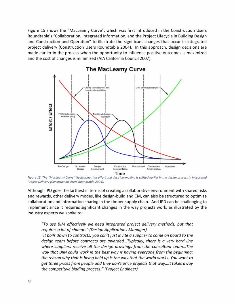
31
Figure 15 shows the “MacLeamy Curve”, which was first introduced in the Construction Users Roundtable’s “Collaboration, Integrated Information, and the Project Lifecycle in Building Design and Construction and Operation” to illustrate the significant changes that occur in integrated project delivery (Construction Users Roundtable 2004). In this approach, design decisions are made earlier in the process when the opportunity to influence positive outcomes is maximized and the cost of changes is minimized (AIA California Council 2007).
Figure 15: The “MacLeamy Curve” illustrating that effort and decision-making is shifted earlier in the design process in Integrated Project Delivery (Construction Users Roundtable 2004).
Although IPD goes the farthest in terms of creating a collaborative environment with shared risks and rewards, other delivery modes, like design-build and CM, can also be structured to optimize collaboration and information sharing in the timber supply chain. And IPD can be challenging to implement since it requires significant changes in the way projects work, as illustrated by the industry experts we spoke to:
“To use BIM effectively we need integrated project delivery methods, but that requires a lot of change.” (Design Applications Manager) “It boils down to contracts, you can’t just invite a supplier to come on board to the design team before contracts are awarded…Typically, there is a very hard line where suppliers receive all the design drawings from the consultant team…The way that BIM could work in the best way is having everyone from the beginning; the reason why that is being held up is the way that the world works. You want to get three prices from people and they don’t price projects that way…It takes away the competitive bidding process.” (Project Engineer)

32
Roles and Responsibilities It’s important to consider the roles and responsibilities of modeling when trying to create a collaborative BIM environment. Typically, the structural engineer will model to the level of detail that suits their purposes, with the primary use being the production of drawings. On collaborative projects, engineers will share their model with downstream users, including the Fabricator, but there are often many challenges for the Fabricator to use the Engineer’s models. First, the models may not be created as accurately as required by the Fabricator, which often leads them to simply create the fabrication model from scratch. Second, in the timber sector there is no design tool that works for engineers and fabricators so there may be issues with data exchange. And lastly, structural engineers’ focus on producing drawings, which remain the contract requirement even on BIM projects, may lead to disconnects between the drawings and the model. These challenges were highlighted by the industry experts we spoke to:
“[In our models and drawings] we [the consultants] don’t show the connection details, we don’t show nails and rivets and welding. That is added by the subcontractor…The [structural] engineer reviews them [the connections], but they are designed by the fabricator. The [structural] engineer specifies the loads, then the fabricator goes and details it and the [structural] engineer reviews it.” (Design Applications Manager) “It really depends on how well the model has been produced and how many details have been managed. If there is a lot of discrepancies between the model and the drawings, it would be simpler to build the model form scratch than to go through the whole thing and try to pick apart all the things that are wrong.” (Fabricator, Project Manager). “Their Revit models are wrong…Our modelers imported the Revit model, and then you look at the contract documents, which are the 2D plans, and it’s wrong…The consultants modified the 2D version of the plan to be right in 2D but is wrong in 3D, all the time, everywhere.” (Fabricator, Engineering + 3D Manager).
BIM Execution Planning Several government- and industry-led efforts from around the world have developed different guides or manuals to facilitate BIM implementation. However, few have gone as far as Penn State in defining best practices in BIM design and execution planning. The Computer Integrated Construction Research Program at Penn State University developed the BIM Project Execution Planning Guide —a buildingSMART alliance project (CIC 2010). This guide provides a practical manual that can be used by project teams to design their BIM strategy and develop a detailed BIM Project Execution Plan (or the ‘BIM Plan’). The BIM Plan outlines the overall vision along with implementation details for the team to follow throughout the project to effectively integrate BIM into the project delivery process. This guide outlines a four-step procedure (see Figure 16) to develop a detailed BIM Plan. The four steps consist of identifying the appropriate BIM goals and uses on a project, designing the BIM execution process, defining the BIM deliverables, and identifying the supporting infrastructure to successfully implement the plan.

33
Figure 16: The BIM Project Execution Planning Procedure developed by Penn State (CIC 2010)
This BIM guide helps project teams to provide a roadmap for BIM implementation that explicitly defines the roles and responsibilities of all the members of the supply chain, the BIM uses that will be implemented, the information exchanges that will occur, and the deliverables that will be produced. Uses of BIM Several uses of BIM in mass timber projects have been identified and are presented in Figure 11, which illustrates how different phases of a mass timber project can be supported by BIM. Although BIM can support a variety of construction projects and most of these uses are not only applicable to mass timber projects, this report emphasizes the specific benefits and synergies that a mass timber project can obtain when using BIM. Visualization Information models provide the opportunity to digitally represent the different systems of a building in a clear and comprehensive manner (Figure 17). BIM also allows users to visualize all the different systems of a building together, which enhances communication among consultants and between consultants and contractors.

34
Figure 17: Examples of enhanced visualization enabled by BIM (TWPC, 2016)
Locally, mass timber projects may be particularly challenged by construction codes that can lead to the development of specific site regulations and the proposal of alternative solutions. In these situations, BIM allows authorities and code consultants to clearly visualize the project and proposed solutions, which can facilitate the approval process. Owners also benefit as they are able to visualize the end-product early on, including interior spaces as shown in Figure 17. Structural Analysis Using virtual models to conduct structural analysis is another important potential use of BIM. Software packages that are being used include RFEM and ETABS, and are able to run an analysis of mass timber structures. The interviews conducted revealed that these models can be generated by employing several different workflows. In the most advanced workflows, the geometry of the structure can be imported from an information model, with RVT and DXF files being successfully used. In some cases, the structural engineer would export the structure from a previously developed information model. In other cases, the structure can be exported from a model developed by the architect. Figure 18 shows the mass timber structural models developed by Fast + Epp and Figure 19 shows a structural model developed by the fabricator StructureCraft for UBC’s Brock Commons project.

35
Figure 18. Sample Mass Timber Structural Models (courtesy of Fast+Epp)
Figure 19: Sample Structural Model created by the manufacturer StructureCraft (image courtesy of StructureCraft).
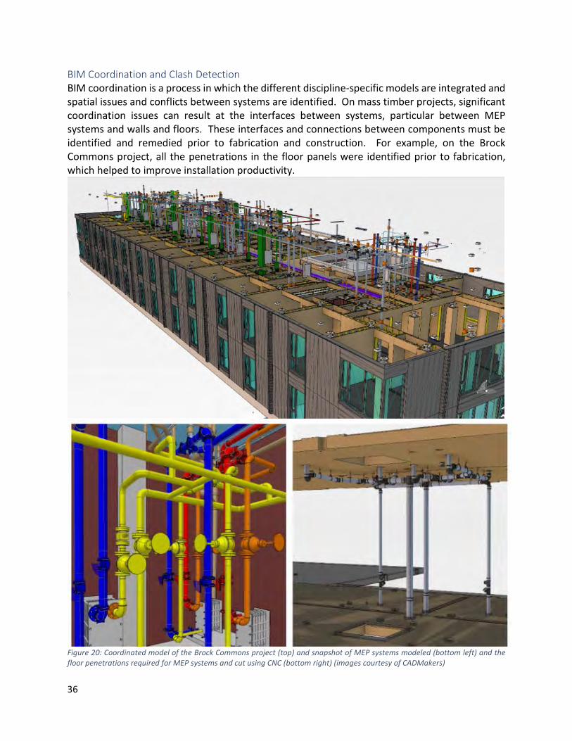
36
BIM Coordination and Clash Detection BIM coordination is a process in which the different discipline-specific models are integrated and spatial issues and conflicts between systems are identified. On mass timber projects, significant coordination issues can result at the interfaces between systems, particular between MEP systems and walls and floors. These interfaces and connections between components must be identified and remedied prior to fabrication and construction. For example, on the Brock Commons project, all the penetrations in the floor panels were identified prior to fabrication, which helped to improve installation productivity.
Figure 20: Coordinated model of the Brock Commons project (top) and snapshot of MEP systems modeled (bottom left) and the floor penetrations required for MEP systems and cut using CNC (bottom right) (images courtesy of CADMakers)

37
Clash Detection software is typically used during the coordination process to identify physical conflicts between building systems in 3D. The goal of clash detection is to eliminate the major system conflicts prior to installation. BIM-based coordination through the model enables numerous benefits, namely, the capacity to resolve spatial conflicts early on and the reduction or elimination of field conflicts, which directly impacts productivity and reduces construction costs and schedule. Figure 21 shows a picture of a design coordination meeting (top left), a coordinated model (top right), and a clash report (bottom) for the Brock Commons project.
Figure 21: Snapshots of a coordination meeting (top-left), a coordinated model (top-right), and a clash report (bottom). (images courtesy of CADMakers)

38
Constructability Review BIM can enhance constructability reviews by allowing professionals to identify suboptimal and infeasible working conditions (see Figure 22). According to a local manufacturer, many things are often overlooked during design that can have a significant impact on fabrication and installation:
[Things that typically get overlooked are] “choice of different types of fasteners, or different types of connectors that are not used in modern mass timber…people aren’t thinking about detailing for movement [due to moisture] and how you detail your connections need to account for that…consultants often don’t understand what a cost-efficient detail is, including the choice of screws or nails, or patterns.” (Fabricator, Engineering + 3D Manager).
The exercise of constructing the project virtually allows constructability issues to be identified quickly and resolved prior to construction. Figure 22 shows an example constructability issue that was identified using the BIM for the Brock Commons project, which could have had a significant impact on construction if it had not been identified early.
Figure 22. Sample constructability issue identified through BIM (image courtesy of CADMakers)
Constructability reviews are enhanced by the development of virtual construction sequences, also referred to as 4D simulations, where temporal structural bracing of the mass timber elements can be evaluated. In the case of the Brock Commons, a potential delay of six to eight weeks was avoided by correcting constructability issues in the proposed installation method of formwork at the concrete cores. The subcontractor corrected the issues after visualizing the model and a corrected method was developed virtually (Figure 23).

39
Figure 23. Corrected sequence for formwork installation enabled through 4D simulation (images courtesy of CadMakers)
Generation of Project Documentation Although BIM adoption has grown significantly within the building design sector, 2D documentation is still the industry norm and the contract deliverable required on most projects. Projects modeled with BIM, however, typically generate this 2D documentation directly from the model after it has been coordinated within the BIM environment. In some cases, consultants are using BIM to generate construction documents that are submitted for tender and specialty trades are using it to generate shop and installation drawings. The generation of these drawings can be achieved through different levels of automation, allowing time-savings across the supply chain. Figure 24 shows the shop drawings that were generated from the Brock Commons model for the timber columns and Figure 25 shows the shop drawings for the timber panels. Figure 26 shows installation drawings that were generated from the model.
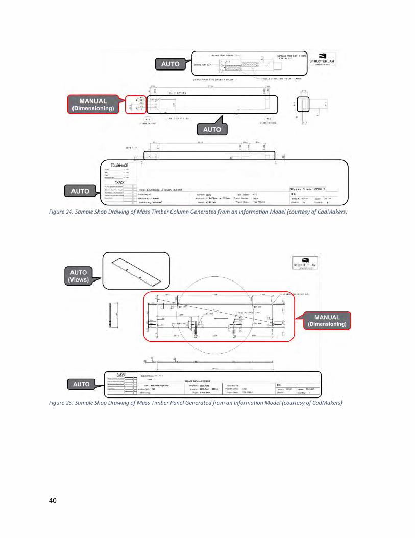
40
Figure 24. Sample Shop Drawing of Mass Timber Column Generated from an Information Model (courtesy of CadMakers)
Figure 25. Sample Shop Drawing of Mass Timber Panel Generated from an Information Model (courtesy of CadMakers)
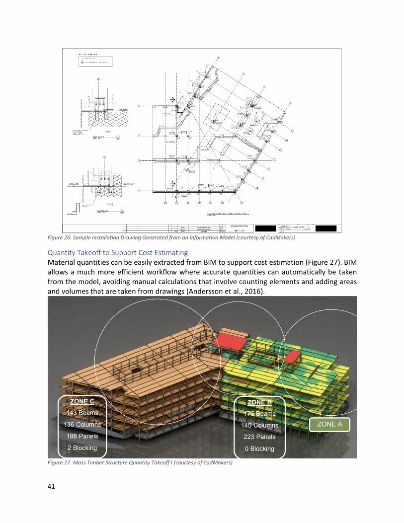
41
Figure 26. Sample Installation Drawing Generated from an Information Model (courtesy of CadMakers)
Quantity Takeoff to Support Cost Estimating Material quantities can be easily extracted from BIM to support cost estimation (Figure 27). BIM allows a much more efficient workflow where accurate quantities can automatically be taken from the model, avoiding manual calculations that involve counting elements and adding areas and volumes that are taken from drawings (Andersson et al., 2016).
Figure 27. Mass Timber Structure Quantity Takeoff I (courtesy of CadMakers)

42
Figure 28. Mass Timber Structure Quantity Takeoff II (courtesy of CadMakers)
Mass timber greatly synergizes with BIM as it is a material that can achieve exceptionally high levels of precision. In mass timber projects, it is not only that BIM can be used to clearly specify the elements of the different systems, but the tight tolerances that are met with wood allow project teams to achieve as-built conditions that match the model. This allows MEP and other trades to explore higher levels of offsite fabrication and trust the bills of materials that are produced from the information model (Figure 29) before manufacture and procurement.
Figure 29. MEP Bill of Materials and As-Built Conditions Brock Commons
Planning Construction Methods BIM allows project teams to study construction sequences at different levels of granularity. This can lead to an early resolution of problems and allow project teams to find optimal solutions. An example of a detailed developed sequence is presented in Figure 30, which illustrates the

43
different components that will be installed at different points in time. Other types of planning can be facilitated using BIM, including safety and water management planning. According to a local contractor with expertise in mass timber construction, it is important to incorporate the participation of the key trades involved in the installation. Having supervisors and workers (and not just high-level management) at meetings to review the installation sequence helps everyone to visualize, agree, and buy into the established timing and methods. This helps to coordinate the work in a comfortable environment, with parties feeling at ease, as opposed to trying to solve a problem onsite when things are not going as planned and emotions are running high in the team. (Contractor, Project Manager)
Figure 30: Example of a mass timber construction sequence (Image Source: Woodworks)
Transportation and Delivery Logistics BIM can also help the installer and manufacturer to coordinate the delivery of the structural elements. On the Brock Commons project, BIM was used to plan out the delivery and unloading cycles for the timber elements (Figure 31). Additionally, each timber element had a pre-established position in the truck (Figure 32). This exercise helps to avoid the misplacement of elements and plan just-in-time delivery conditions for construction sites where space is limited and elements cannot be stored onsite.

44
Figure 31. Brock Commons sequencing including delivery and unloading (courtesy of CadMakers)
Figure 32. Sample Mass Timber Structure Loading Plan
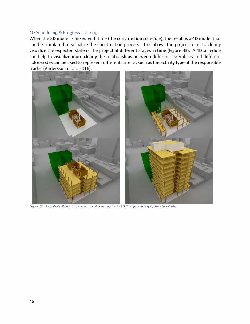
45
4D Scheduling & Progress Tracking When the 3D model is linked with time (the construction schedule), the result is a 4D model that can be simulated to visualize the construction process. This allows the project team to clearly visualize the expected state of the project at different stages in time (Figure 33). A 4D schedule can help to visualize more clearly the relationships between different assemblies and different color-codes can be used to represent different criteria, such as the activity type of the responsible trades (Andersson et al., 2016).
Figure 33. Snapshots illustrating the status of construction in 4D (image courtesy of StructureCraft)

46
BIM can also facilitate more detailed tracking of the state of the project, making it easy to compare the scheduled or planned state of the project to the actual state. As with 4D scheduling, a color-code can be developed to indicate the delayed and impacted work (Figure 34).
Figure 34. Sample BIM Project Tracking (source unknown)
Lifting and Center of Gravity Analysis BIM can also be used to facilitate lifting and center of gravity (COG) analysis of mass timber elements, especially mass timber panels. The elements will typically come with pre-installed fasteners that work as lifting anchors. This process helps to increase crane efficiencies and decrease the lifting cycles. Onsite safety can also be enhanced by this practice. Figure 35 shows the model used to identify the COG and the lifting points (left) and snapshots of the mass timber panels being placed on site (right). Using BIM tools, practitioners can write scripts that can automatically locate the COG and generate the lifting points details. The elements will typically come to the site with pre-installed fasteners that work as lifting anchors. Digital Fabrication One of the main drivers of the use of wood as a construction material are the technological advances enabled by digital manufacturing (Mayo, 2015). These technological advances include the replacement of carpentry shops by computer-assisted design and processes and robotic

47
controlled precision tools (Mayo, 2015). Computer numerical controlled (CNC) machines have become more common and advanced. While CNC machines that can cut in three axes are common in wood manufacturing, we are now seeing high-tech CNC machines that resemble robotic arms allowing highly crafted and unique elements to be fabricated with an accuracy in the ranges of 0.05 to 0.1mm (Mayo, 2015). Figure 35 shows a digital representation of a fabrication model from CADMakers, fabricated components at Structurelam, and the pictures of the actual installation on the Brock Commons site. A more detailed discussion of digital fabrication tools is provided in a subsequent section. According to a leading Architect, for digital fabrication to work, fabricators have to be able to trust the as-built conditions to be in accordance with the project documents, which can increase their levels of offsite fabrication. This practice is often required in local concrete projects since typical discrepancies between the structure and drawings can require some elements to be adjusted and dimensions to be changed. (Architect, Principal)
Figure 35: Snapshots of fabrication models from CADMakers, actual fabrication at Structurelam, and installation on the Brock Commons site.
This section reviewed the many different uses of BIM for the mass timber sector. To support these different uses, the workflows between the different stakeholders must be managed and supported to successfully implement BIM. BIM Workflows BIM workflows vary depending on the particular procurement method used and whether the fabricator and installer are engaged early. This section presents the typical sequence of processes for implementation of BIM in mass-timber construction projects and identifies the typical information exchanges between different organizations across the different stages of development. We focus on the workflows across the following six project stages:
1. Conceptual Design 2. Design Development 3. Construction Documentation

48
4. Detailing 5. Fabrication 6. Assembly
There are different disciplines that can be involved in a prefabricated mass-timber project. The diversity of organizations involved is strongly dependent on the project circumstances and the complexity of the project context, i.e., the project delivery type, contractual conditions, the level of prefabrication, and the complexity of modular components. Since the most observed mass-timber projects in this study followed more of an integrated delivery approach, we assume that the different project stages contain simultaneous collaborations between different disciplines as separate, independent organizations. Thus, the typical disciplines involved in a prefabricated mass-timber project besides the owner can be categorized as following:
1. Architect 2. Structural Consultant 3. MEP Consultant 4. Construction Manager 5. Mass-timber Manufacturer (Detailing and Fabrication) 6. Mass-timber Installer
Figure 36 shows the ‘ideal’ workflows in collaborative BIM-enabled projects where there is significant collaboration and early engagement of the mass timber manufacturer and installer. The workflow diagram shows the processes and information exchanges between different disciplines from the conceptual design stage to the assembly stage based on the process map developed by AISC (American Institute of Steel Construction) for steel construction projects [1]. In this diagram, all BIM-based processes are shown as blue boxes. The white boxes represent the exchanged information and process outcomes, such as current models, documents, reviews, comments, and drawings. The abbreviations in the white boxes indicate the sender and receiver of the exchanged information as well as the corresponding stage. For example, “AS-1” shows that the architect (A) is sending some information or documents to the structural engineer (S) in stage 1 (conceptual design stage). The light green boxes show the specific processes that are enabled by greater collaboration with the mass timber manufacturer and installer.

49
Figure 36: BIM Workflows in Mass-Timber Construction Projects highlighting typical processes and information exchanges (blue) and processes that are enabled by greater collaboration and early engagement of fabricators and installers (light green).

50
Conceptual Design In construction projects with high levels of prefabrication, integrative delivery approaches are essential. Therefore, it is very valuable to involve the structural and MEP consultants in addition to the architect from the very beginning of the project. In such project settings, the architect should develop the main conceptual architectural model and share this with the structural and MEP engineer (AS-1, AE-1). In this way, an iterative approach between these project participants should begin. Based on feedback from other disciplines (SA-1, EA-1), the typical architectural conceptual model should be developed in this stage, which usually includes the:
1. Building shape, layout, height, and number of stories 2. Site plan 3. Space allocation
The structural engineer’s review process should include the preliminary load estimation, investigation of different structural systems for the building to withstand vertical and lateral loads, and determination of the most appropriate structural system for the building. The structural engineer should then break down the structure into the site-built concrete part and the prefabricated timber part after consultation with the manufacturer to avoid manufacturability issues in the later stages. After development of structural preliminary model, the design is ready to be sent to the architect along with the potential probable design change requests in the layout or in other general architectural properties of the building (SA-1). The manufacturer and construction manager should be involved in design-assist role to have a higher level of integration in the project and to implement DfMA approach efficiently. The integration of these downstream project participants with advisory and consultative involvement from the very beginning of the project in this stage can help the design team to identify and address many manufacturing, transportation, material, and installation limitations of the design. The manufacturer should help the design team in breaking down the structure into prefabricated components such that the wastage of raw materials is minimized. Another benefit of their involvement is instant review on the manufacturability of prefabricated components for their shapes, sizes, and material based on available equipment and technology used in the factory (MA-1). Similarly, the construction manager should also evaluate the design based on available space onsite, and any other site obstruction that needs to be considered as site limitations (CA-1) early on in the project. Similar to the structural consultant, the MEP consultant should also develop their preliminary MEP design models based on the conceptual architectural model and send it back to the architect (EA-1). These processes and information exchanges should be iterated between the architect, and the structural, MEP engineer, and manufacturer until they come up with an acceptable solution. After a coordinated preliminary design is developed, the architect should send the design model to the construction manager for preliminary estimation of the project (AC-1) and then the construction manager sends the initial estimation report back to the architect (CA-1). Design Development After the preliminary design stage and the approval of its outcome by the stakeholders, the disciplines-specific models are ready to be further developed and detailed. In this stage, the

51
architect should commence working on the design model and finalizing the plans. Similar to the previous stage, the processes here are also iterative. The architect should develop the design model to a certain level of detail (LOD) so that the structural and MEP consultant can start designing and modeling the building’s structural and MEP components. Then the architect should send the detailed architectural model to the structure engineer and MEP engineer for their disciplinary design model development (AS-2 & AE-2). In this stage, the architect should revise the architectural design model iteratively based on the feedback received from the structural engineer (SA-2) and MEP engineer (EA-2). In the design development stage, the structural engineer should incorporate details related to the structural systems and structural members from the preliminary structural model. After achieving sufficient level of detail of structural systems and frames of the building, the model should be exported from the structural BIM to appropriate structural analysis programs for conducting the necessary structural simulations and analysis. In this way, a detailed structural model should be developed by specifying structural members of the building, and should be sent to the architect (SA-2). Similarly, the involved MEP consultant should develop detailed mechanical, electrical, and plumbing design layout in this stage. After development of MEP design layouts, they are ready to be sent to the architect for coordination (EA-2). Once the detailed and discipline specific design models are developed by all the involved disciplines, it is (depending on the project circumstances and contractual conditions) usually the architect’s responsibility to carry out the coordination between different models. In this process, all disciplinary design models should be merged into an appropriate BIM coordination tool, such as Autodesk Navisworks, to identify the potential design issues and discuss further solution options. This process needs to be carried out through various collaborative meetings that are known as “coordination meetings.” Once all the clashes are resolved through such coordination, each discipline-specific model is called as a coordinated model, which means that this model is coordinated with other disciplines and does not have any clashes with other models from other disciplines. The construction manager and the manufacturer should also be involved in the design development stage as a part of integrative approach and should participate in coordination meetings to review each different design models. Their main input during the coordination meeting would be to identify the manufacturability and constructability issues in the design based on their experience and knowledge (CA-2, MA-2), as explained above. Once the coordinated design model of the building is developed, the architect should send the design model to the manufacturer for further fabrication-level detailing. The coordinated design model should also be sent to the construction manager to support construction. Construction Documentation Once the coordinated detailed discipline-specific design model is developed, the structural engineer and MEP engineer should send their disciplinary contract model to the architect along with the design documents (SA-3 & EA-3). The architect then should send the coordinated design

52
model to the construction manager for detailed time, cost, and labour estimation (AC-3). The construction manager directly takes-off the quantity from the coordinated design model and calculates detailed future costs by considering material cost, labour cost, equipment rental cost etc. They also should develop the detailed construction schedule of the project. From the coordinated design model, the construction manager develops bids for the sub-contracting fabrication, installation work and sends the bid information to the design team (CA-3). Detailing In this stage, the manufacturer receives the coordinated design models from the architect and the structural engineer for further detailing and developing the required shop drawings (SM-3 & AM-3). Ideally, the manufacturer should import the design model into their appropriate BIM authoring tools and insert detailing information, such as connections, screws, bolts, penetration etc. BIMs created by the Manufacturers for mass-timber usually use CNC machines to manufacture the timber components. For this aim, different BIM tools offer solutions to generate CNC machine commands (the next section describes this in detail). Furthermore, they should also produce shop drawings directly from the fabrication model. This approach is much more efficient, reliable and accurate but requires significant coordination and collaboration. The added fabrication information and the detailing of the shop drawings are mainly based on the empirical knowledge of the manufacturer. After shop drawings are developed, they should be sent to the design teams for their review and confirmation of the consistency between the shop drawings and the design models (MA/S-4). In the fabrication design review process, the architect and the structural engineer should comment on the fabrication design (AM-4 & SM-4), noting any discrepancies found with their designs. The manufacturer should also share this detailing information with the installer to check that there are no constructability issues. The installer should analyze the fabrication model to check that each connection is constructible and there is sufficient working space for installation (IM-4). For example, the installer may find insufficient working place at some place to connect the panels and tighten the bolt. These identified issues then should be addressed and corrected in the detailing stage. Manufacturing Once the shop drawings are reviewed and approved by the architect and structural engineer, the mass-timber manufacturer should share the installation drawings and documents with the installer (MI-5). The mass-timber installer should analyze the different installation sequences from the installation drawings and documents, and should generate an optimized installation sequence. The installer develops the optimized installation sequence through an iterative process with the construction manager (IC-5 & CI-5). The installer should also share the optimized installation sequence with the manufacturer (IM-5), so that they can develop the production plan of the prefabricated components. The manufacturer should share the production plan with the construction manager and the installer (MC/I-5) for their reviews (IM-5 & CM-5) and for necessary updates.

53
Using the approved fabrication model, the manufacturer can create the CNC commands and start the fabrication process with the coordinated sequence. As mentioned earlier, there are BIM tools and extensions that provide solutions for generating commands for CNC machines. In this stage, the construction manager should work with the installer to coordinate the fabrication process of the timber components according to the installation sequence to achieve just-in-time delivery of the timber components. Furthermore, in this stage, the construction manager should develop an onsite coordination strategy for the assembly process, and should identify and resolve potential onsite conflicts between different trades working simultaneously during the assembly of the prefabricated components. Such information could be used for the development of the 4D simulation showing the virtual construction of the building process, which can help to improve the productivity of the onsite crew. Assembly Design models along with the 2D plans should be used during the assembly stage in weekly or bi-weekly meetings for effective communication between different disciplines. The mass-timber installer should continuously give updates about the installation status to the construction manager (IC-6) to update the model and coordinate with other ongoing processes on the site. The updated detailed model should be used by the construction manager for quality control of the installation process and identification of deficiencies such as displaced installation of the prefabricated components from the planned location. The updated 4D simulations could be used to track the onsite construction activities in a timely manner and compare it with planned schedule. For this aim, it is necessary to continuously update the schedule and the corresponding models. It should be noted that quantity take-offs from updated models and 4D simulations can be used for ordering material and procuring equipment in a timely manner, and also to follow a just-in-time delivery approach for prefabricated components from the factory. BIM Tools and Information Exchange Based on the many uses of BIM described in Section 2 and the many information exchanges described in Section 3, we will now describe the BIM tools used to design and manufacture timber components and then describe the interoperability issues that may result when sharing BIM data across different disciplines in the supply chain. We first describe common design tools used by design consultants, including architects and structural engineers, and then describe manufacturing tools commonly used in the mass timber sector. Common Design Tools This section will describe the common design tools used by structural engineers and manufacturers in the mass timber industry. 1. Autodesk Revit
Autodesk Revit is BIM authoring software developed by Autodesk, which has many features tailored for modeling and management of architectural, structural, and MEP models. This has made it an essential tool for architects, engineers from different disciplines and construction

54
professionals. Revit has become the most dominant BIM software tool in North America and many European countries. Revit is a parametric modeling tool that can be used for conceptual design, construction documentation, structural design, and MEP building system design. Moreover, it has several embedded analysis tools for building performance analysis, heating and cooling, daylight, (artificial) lighting, structural calculations, spaces and zones, etc. There are several specialized Revit extensions developed for design and construction of timber projects that are available on the Autodesk App Store. These extensions facilitate timber framing, the generation of shop drawings, and communication between Revit and the CNC machine. In particular, “hsbTimber” by hsbcad is an extension to Revit specifically developed for detailing timber models and is able to generate BTL files from BIM (Figure 37).
Figure 37: Snapshot of hsbTimber extension for Autodesk Revit to support timber detailing.
Revit supports a variety of different BIM and CAD formats including IFC, DWG, DXF, FBX, gbXML, SAT, and SKP. This allows the Revit users to exchange and share models with many different software tools, which subsequently increases the level of collaboration between different project disciplines in a project. However, Revit natively does not support STEP files, which is a very common standard format for manufacturers ‒ including mass-timber ‒ to produce prefabricated building components. Another drawback with Revit is importing models from other tools, such as DWG, which causes loss in data exchange and makes it difficult to use as an information management tool for collaboration and manufacturing purposes. Furthermore, Revit does not nest information regarding the fabrication of building components so that they can be used in the manufacturing process. It only manages geometric and non-geometric information regarding the objects and the project, and not how their manufacturing process should be executed.

55
Therefore for DfMA purposes, Revit needs to be used in combination with other complementary manufacturing tools, which are discussed in the next sub-section. 2. Tekla Structure (Tekla)
Tekla is a powerful BIM tool developed by Trimble that primarily specializes in structural steel and concrete detailing and fabrication, though their support for timber is growing. Tekla is unique in that it enables users from design through detailing and fabrication. Figure 38 Tekla also supports numerous file formats, including IFC, STEP, DXF, DWG, and SKP. Tekla is capable of interacting with most planning and manufacturing automation systems that the fabricators of steel structures and precast concrete elements use. Furthermore, the information, such as logistic plans, assembly status, schedules and material traceability, can be also included in a Tekla model, which helps to plan and monitor the project processes. Tekla has recently included some basic wood components, such as wood frames and wood connectors in the software releases after 2017. All timber structures are detailed with Tekla Structure, and the working plan to CNC machine is made with hsbcad. Figure 39 shows a timber model created using Tekla for a large timber campus project in Finland.
Figure 38: Tekla supports design, issue tracking, shop drawing review, and detailing, as shown for the steel models created for the Vancouver Convention Centre project (images courtesy of Glotman Simpson and Dowco)
Figure 39: Snapshot of Tekla timber model created for a large timber campus project in Finland (image source: Tekla website)
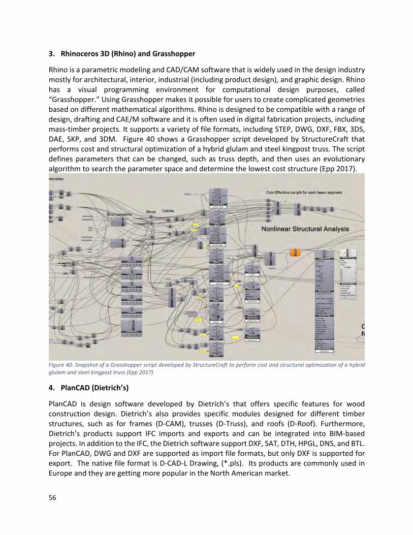
56
3. Rhinoceros 3D (Rhino) and Grasshopper
Rhino is a parametric modeling and CAD/CAM software that is widely used in the design industry mostly for architectural, interior, industrial (including product design), and graphic design. Rhino has a visual programming environment for computational design purposes, called “Grasshopper.” Using Grasshopper makes it possible for users to create complicated geometries based on different mathematical algorithms. Rhino is designed to be compatible with a range of design, drafting and CAE/M software and it is often used in digital fabrication projects, including mass-timber projects. It supports a variety of file formats, including STEP, DWG, DXF, FBX, 3DS, DAE, SKP, and 3DM. Figure 40 shows a Grasshopper script developed by StructureCraft that performs cost and structural optimization of a hybrid glulam and steel kingpost truss. The script defines parameters that can be changed, such as truss depth, and then uses an evolutionary algorithm to search the parameter space and determine the lowest cost structure (Epp 2017).
Figure 40: Snapshot of a Grasshopper script developed by StructureCraft to perform cost and structural optimization of a hybrid glulam and steel kingpost truss (Epp 2017)
4. PlanCAD (Dietrich’s)
PlanCAD is design software developed by Dietrich’s that offers specific features for wood construction design. Dietrich’s also provides specific modules designed for different timber structures, such as for frames (D-CAM), trusses (D-Truss), and roofs (D-Roof). Furthermore, Dietrich’s products support IFC imports and exports and can be integrated into BIM-based projects. In addition to the IFC, the Dietrich software support DXF, SAT, DTH, HPGL, DNS, and BTL. For PlanCAD, DWG and DXF are supported as import file formats, but only DXF is supported for export. The native file format is D-CAD-L Drawing, (*.pls). Its products are commonly used in Europe and they are getting more popular in the North American market.

57
5. ArchiCAD
ArchiCAD is BIM software specializing in architectural design developed by Graphisoft. Although ArchiCAD is not as dominant as Autodesk Revit in the AEC domain, it is being widely used by architecture firms in over 100 countries, such as US, UK and Australia. For dealing with the wooden components, such as wooden envelope (wall framing, column and beam), floor and roof, ArchiCAD has a specific add-on called ArchiFrame, which is capable of interacting with CNC machines. ArchiCAD supports different CAD and geometric formats, such as IFC, DWG, DXF, and 3DM (Rhino), although it does not support STEP files natively.
Figure 41: Snapshot of ArchiCAD with add-on ArchiFrame to support timber design and detailing.
Common Manufacturing Tools
1. Cadwork
Cadwork is the leading 3D CAD/CAM software specializing in timber construction, and is mainly used for architecture and fabrication modeling purposes. Cadwork is specifically developed for timber construction modeling and has various timber specific features from joint details to element modules for complete buildings. Complete walls, floor and roof systems can be built in Cadwork with a range of preset wood panel construction, stud frame construction, and other system methods. Furthermore, Cadwork provides special details, like joints between timber components, as the parameter-configured terminal-types, and the user is able to save these details for the following fabrication steps. Cadwork supports IFC, SAT, 3DM, DTH, IGES, DXF/DWG, STEP and BLT files, which makes it a great tool in collaborative projects. Shop drawings of every piece of building model can be exported directly from Cadwork, which facilitates the information exchange between the engineer, the modeler and the installer. With the Cadwork Machine Module, the 3D model of components can be sent directly to the CNC machines used for fabrication of timber building elements. This direct connection to the CNC cutting machine prevents data loss and human error created in other approaches where the direct connection between the model and the CNC machine does not exist.

58
2. Autodesk Inventor
Inventor is developed by Autodesk as a tool to support engineers in the manufacturing domain in tasks related to parametric modeling, 3D mechanical design, documentation, and product simulation. It has specific features for simulation analysis, basic stress analysis and surface modeling with broad application in industrial equipment design, automotive design, fabrication, and building product design. Inventor has not been widely used in mass-timber projects as a parametric modeling tool. However, Autodesk is continuing to work on the new features for Inventor to make it more attractive to the manufacturing domain and make it more competitive with tools like CATIA. Nevertheless, Inventor has a fully integrated extension for woodworking, called “Woodwork” that is developed external to Autodesk. This tool is developed for designing wooden furniture with the capability of preparing CNC files that can be used for timber fabrication as well. Inventor supports different file types, including STEP, IGES, IDW, DWG, IPT, IAM, and IPN, which gives Inventor users the option to collaborate with other disciplines who use tools other than Autodesk products. 3. SEMA software
SEMA software is a German software company, specializing in the development of timber construction software. It is a 3D CAD/CAM software for planning, designing and production for timber and stairs construction. This software is specifically developed for timber construction modelling and it contains standardized component libraries and families for roof, wall, and stairs construction. SEMA also offers suitable timber fasteners/connections, which are easy to insert into detailed drawings. It can also generate direct plans, material lists, quantities, and piece lists from the model. SEMA software supports IFC, BTL, DXF/DWG, SCI, SCI-XML, RCE, and MXF files to support an integrated approach in timber construction. It can also generate shop drawings from the model, and can communicate directly with CNC machines used in fabrication of the building element. This again, helps in reducing data losses and human errors created in other approaches where direct connection between the model and CNC machine does not exist.

59
Figure 42: Snapshots from SEMA Software
4. CATIA
CATIA is one of the leading engineering and design software in the manufacturing domain developed by the French company Dassault Systèmes. It is mainly developed to address challenges regarding CAD and CAE/M, and so it is widely used in the automobile and aerospace industry. In the AEC domain, CATIA is also being used to a very limited extent for preparing prefabrication models to ease the manufacturing process. Currently, there are limited construction-specific features included, i. e., no predefined and standardized building components, building related object relations and rules (for instance, a window has to be attached to a wall, etc.). However, CATIA is a parametric modeling tool and has the capability of creating useful construction related features by users. Dassault Systèmes is currently working on solutions suitable for the AEC domain and CATIA might be used more in this domain in the future. CATIA is included in this report because it was the software used to design and detail the mass timber structure for the Brock Commons Project by CADMakers, an integrated technology company working in the construction and manufacturing space. CADMakers have developed significant capability in the design and manufacturing of mass timber elements using Catia that

60
allows them to model parametrically and develop scripts that can automatically generate many aspects of design and manufacturing information. Figure 43 shows a snapshot provided by CADMakers illustrating the Catia interface and relevant data for CLT Panel installation. We have provided numerous examples throughout this report showing the use of Catia in mass timber construction for the Brock Commons project.
Figure 43: Snapshot of Catia interface for CLT panel installation developed by CADMakers (image source CadMakers).
5. Cambium
Cambium is a software that can communicate with all machines produced by the company Hundegger and is able to manage and optimize the production processes. Cambium is tailored to meet the needs of timber construction and fabrication with simple operation inputs. Furthermore, it can map the entire processes from the design throughout the production of wood elements. Cambium can import data from commonly used CAD systems, such as Cadwork. As illustrated in this section, a variety of BIM tools are available to support the design, detailing, and fabrication of mass timber components. Given the increasing specialization and growing number of BIM tools, information exchange between systems remains a significant issue. Although data standards help to address some of these issues, challenges remain in sharing non-geometric data in particular, and supporting translation that works for a variety of CNC machines. Information Exchange and Interoperability BIM-based DfMA projects with high degrees of prefabrication require higher levels of accuracy, which must be enabled by interoperability between design and fabrication software tools. Exchanging information within each project stage is usually a less complicated operation, since most software developers try to support data exchanges between similar platforms. For instance, in the design stage, Autodesk Revit, ArchiCAD, and Tekla can exchange models using the IFC format. However, there might be application-specific objects that are not supported by IFC and

61
they can be lost during model exchange. Another issue is related to the different versions of IFC. The latest version is IFC4 (2013), however, many tools still follow the schema of IFC2x3 (2006), which may create interoperability issues. Similarly, software from the manufacturing domain can exchange models using STEP files. Interoperability issues appear when it is necessary that software from different domains exchange information. For instance, importing STEP files in Revit and Tekla is not directly supported, and CATIA and Cadwork still have some issues integrating IFC files. The data exchange between IFC and STEP can result in loss of information, since the IFC is developed for capturing different characteristics of building components and STEP has more of a focus on product manufacturing. This difference is clearly visible when, for instance, comparing Autodesk Revit with CATIA. Revit works with object classes (called Families) that can be created within Revit or imported from external libraries, whereas in CATIA, each object in the model needs to have information regarding its manufacturing, including the order of different actions, like cutting, drilling, folding, etc. Figure 44 shows the representation of the same model that was exchanged between different software systems.
Figure 44: Representations of the same model exchanged between different software using STEP.

62
It should be noted that many design tools can be used for detailing purposes, such as Tekla. However, in the context of mass-timber, many still lack appropriate timber-related features. For instance, in mass-steel manufacturing, Revit can be used to create the detailing, but the same tools are not suitable for mass-timber manufacturing. This reality forces the project participants to switch between tools and therefore, the possibility of facing model exchange issues in mass-timber projects is generally higher than mass-steel projects. Since the tools that are used for controlling and operating the CNC machines are originally developed for the manufacturing domain, the workflows that include mainly software from this domain generally have a less error prone process. For instance, using CATIA for the design and detailing, then Cadwork for finalizing the detailing and generating machine commands, and finally using Cambium to operate the CNC machines, has a relatively high efficiency from a data exchange perspective. However, in this workflow the advantages of BIM in project design and coordination are limited because these tools are typically only used by manufacturers. On the contrary, when BIM tools are used for the design and even for the detailing, at some stage the model needs to be transferred to a middleware software like Cadwork to prepare the machine commands and finalize the detailing. This process is, as mentioned above, combined with exchange issues and careful quality control is necessary. Figure 44 shows an example of geometric information exchange from Rhino into Cadwork as a workaround. Although Rhino is widely used in design firms, it is not a BIM tool and does not contain semantic information, though it can be used as a middleware for geometry transformation.
Figure 45: STEP file in Rhino (left) and Cadwork (right)
Table 6 gives an overview of the different software tools described above and the common file formats that they support. Note that these supported formats should be used with caution, and it is highly recommended to establish rigorous quality control measures for reducing the amount of data loss in a project.

63
Table 6: An overview about the supported common formats by different design and manufacturing tools (I: Import, E: Export, W: with extra extension)
Native File Format
IFC (*.ifc)
STEP (*.stp)
BTL (*.btl)
DWG (*.dwg)
DXF (*.dxf)
Autodesk Revit *.rvt I/E - W I/E I/E
ArchiCAD *.pln I/E W - I/E I/E
Tekla Structure *.db1 I/E I/E - I/E I/E
Rhinoceros 3D *.3dm W I/E - I/E I/E
PlanCAD *.pls I/E - I/E - I/E
CATIA *.part - I/E - I/E I/E
Cadwork *.3d I I/E I - E
Autodesk Inventor
*.ipt, *.iam, *.ipj
- I/E W I/E I/E
SEMA
Conclusions BIM coupled with DfMA creates the ideal situation where the team is organized from the start to develop and optimize BIM for the project lifecycle. It is critical that the project is organized with early engagement of key project stakeholders, particularly the fabricator, detailer and installer for mass timber projects, and that everyone is incentivized to work together. BIM uses throughout the project timeline must be determined early on and BIM execution planning must clearly articulate the roles and responsibilities, the level of model development, and the timing for BIM deliverables. To maximize digital fabrication, all relevant systems must be modeled with precision so that all connections and penetrations are clearly identified. BIM workflows between the different project stakeholders and specific information exchanges and model ‘handoffs’ should be mapped out. BIM tools for mass timber design and manufacturing provide significant functionality to support design and manufacturing but there are challenges. To ensure that the models are reliable and useful, structural engineers must work closely with the detailer/fabricator to ensure that the model is created to an appropriate level of detail and accuracy. Otherwise, it may be more efficient for the fabricator to start from scratch, thereby diminishing the efficiency of modeling. In contrast with mass steel construction, there are no software tools that are being used by both structural engineers and fabricators. As a result, interoperability will remain an issue that has to be managed for mass timber projects.

64
Findings: Industry Readiness Survey
A survey was conducted between April and June 2018. The survey was distributed through FII and the local and regional construction associations such as BC Construction Association, Vancouver Regional Construction Association and the BC Construction Roundtable. A total of 27 responses were recorded with 20 surveys completed. Table 7 shows the distribution of survey respondents. All respondents were located in BC, with some respondents employed for companies that have offices across Canada or around the globe. Table 7 - Distribution of survey respondents
Architecture 5 Engineering - Structural 4 General Contractor 2 Manufacturer/supplier 3 Other (please specify) 6
*Other include: clients, geotechnical engineers, and construction engineers and managers The survey touched on three topics as outlined in this report: BIM adoption, experience with Mass timber construction and use of DfMA principles. The respondent pool had a good rate of adoption of BIM and experience in mass timber construction. DfMA adoption rates are lower.
All architects, engineers and manufacturers surveyed had adopted BIM whereas only 50% of general contractors had. All general contractors and manufacturers had worked with mass timber construction. Further to this, DfMA adoption rates were highest amongst suppliers and
10%
65%
25%
Mass timber construction
No Yes N/A
35%
35%
30%
DfMA adoption
No Yes N/A
10% 5%
85%
BIM adoption
No What is BIM? Yes
Figure 46 - BIM, Mass timber construction and DfMA Adoption rates

65
manufacturers (66.7% adoption rates) with general contractors and structural engineers showing 50% adoption rates among respondents from that category. Finally, all respondents who adopted DfMA principals had adopted BIM. BIM Adoption For the respondents who indicated having adopted BIM, 75% qualified themselves as expert or advanced. The remaining 25% were evenly distributed across the three lower capability levels. Capabilities were rated according to the scale below:
• Expert - use of parametric design, complex analysis, etc. on all projects • Advanced - BIM is used on all projects in an extensive fashion. • Intermediate - BIM is used on most projects, but in a limited fashion • Beginner - BIM used for 2D documents, visualization and some analysis on a small
number of projects • Novice - very basic skills, BIM used for 2D documents and visualization on a small
number of projects
When asked about the top BIM uses in their organizations, respondents indicated that documentation, visualization and coordination were the top uses of BIM (Figure 47).
Figure 47 - Top BIM uses
0%2%4%6%8%
10%12%14%16%18%20%

66
The respondents also identified challenges associated to BIM adoption and implementation. Lack of capabilities (internally or generally within the local industry) was seen as the biggest challenge. Other challenges included software capabilities, change management, including rethinking coordination workflows, standardization and demonstrating the value of BIM (Figure 48)
Figure 48 - Top challenges to BIM adoption
Interoperability between project team members and the different software platforms did arise as a challenge for a number of respondents. As previously mentioned, open standards for BIM provide a framework to overcome these interoperability issues. When asked if they had used open BIM on projects in the past, namely IFC files for information exchanges, only 33% of respondents indicated that they had; 25% of respondents had never heard of open standards for BIM. When asked about software platforms in use, Autodesk Revit as a BIM tool came out on top among respondents. As identified in the interviews, Cadworks was a popular choice for manufacturers. Rhino 3D, Trimble SketchUp, Nemestcheck Vectorworks and Autodesk Navisworks were also indicated as used by multiple respondents. Analysis software such as ETABS and SAP 2000 were solely used by structural engineers. Figure 49 indicates the different BIM tools in use by discipline.
0%
1%
2%
3%
4%
5%
6%
7%
8%
9%
10%

67
Figure 49 - BIM tool use by discipline
0 1 2 3 4 5 6 7 8
Bently - Microstation
Dassault Systems - Enovia
Dassault Systems - Smarteam
Dassault Systems - 3D experience
Synchro
mSIX
Trimble - Total Station
Trimble - Vico Office
Robot Structural Analysis
Autodesk - BIM 360 suite
Dassault Systems - Catia
Dassault Systems - Solidworks
Solibri Model Checker
Tekla
Tekla BIMsight
3D Laser Scanner (Trimble, Leica or other)
SAP 2000
Graphisoft - ArchiCad
ETABS
RFEM
Autodesk - Navisworks
Nemestchek - Vectorworks
Trimble - SketchUP
Rhinoceros 3D
CADWORKS
Other (please specify)
Autodesk - Revit
Architecture Engineering - Structural General Contractor Manufacturer/supplier Other (please specify)

68
Another question looked at the use of third party content within models. When asked whether respondents used third party content downloaded from the internet, 92% indicated that they did. Moreover, when asked if a regional or national BIM object library would be useful to the respondent or the respondent’s organization, nearly 40% indicated that it would be either very or extremely useful (Table 8). Table 8 - Utility of a regional or national BIM object library
Extremely useful 17% Very useful 25% Somewhat useful 33% Not very useful 8% N/A 17%
With regards to the benefits of BIM, respondents identified the top three that they have been getting on their projects. The biggest benefits of BIM identified were reduction in errors and rework and better visualization of projects leading to better project understanding. Other benefits included improved coordination, accuracy, and overall better information (Figure 50).
Figure 50 - Benefits of BIM
For the respondents who had not adopted BIM, all respondents indicated that they had the intention of adopting BIM within the next 6 to 24 months. Reasons to not adopt BIM included, lack of skills, lack of demand for BIM, and costs of implementation.
0%
2%
4%
6%
8%
10%
12%
14%
16%
18%
20%

69
Mass Timber Construction The respondents who indicating having experience with mass timber construction were surveyed on how mass timber projects have been delivered compared to other types of construction systems (concrete and steel). The level of project integration was surveyed with respondents indicating that the mass timber projects in which they were involved were more integrated that other projects (Table 9). Moreover, 83% or respondents indicated that the mass timber projects they had worked on used some form of digital fabrication. 62% of respondents indicated that digital models were developed in-house to support the manufacturing process. Table 9 - Level of project integration
Much more integrated 25% More integrated 58% No change 8% Much less integrated 8%
The manufacturers surveyed indicated that they usually or only sometimes obtained models from the project team to support their process. In the cases they did receive models from project team members, a great deal or a lot of work is commonly required to modify/edit the base model and produce the in-house information model. The responses were more varied for other professionals as shown in Figure 51.
Figure 51 - Amount of work required to edit base model
0% 10% 20% 30% 40% 50% 60% 70% 80% 90% 100%
Architecture
Engineering - Structural
General Contractor
Manufacturer/supplier
Other (please specify)
A great deal A lot A moderate amount A little N/A

70
Adoption of DfMA Principals For the respondents who indicated having adopted DfMA principals, the range of capabilities was distributed evenly across the scale indicated below:
• Expert — DfMA principals deployed on all projects • Advanced — More advanced set of DfMA principals applied to a large number of
projects • Intermediate — More advanced set of DfMA principals applied to a small number of
projects • Beginner — Basic DfMA principals applied to a small number of projects • Novice — Basic DfMA principals applied to a very limited number of projects
The challenges of adopting DfMA principals identified by survey respondents were: the standardization of processes, ensuring that the design optimization/process is actually optimising for the correct things in the fabrication and installation, standardization of feedback loops between Shop/Site/Office and tracking pros/cons of decisions made early in the DfMA process, and establishing clarity of scope and handoff of risk in the DfMA process. The main benefits of DfMA identified by survey respondents were: greater team buy-in to concepts and projects, increase in efficiency, more cost-effective projects, production to standards, quality control, speed of execution and upfront involvement in the project. Interestingly enough, one respondent indicated that DfMA principally benefits the manufacturer, demonstrating an asymmetry of project incentives. For the respondents not having adopted DfMA principals, a majority indicated not having the intention or intending to adopt DfMA on a 5 year + horizon. The reasons respondents didn’t adopt DfMA were articulated around 4 main reasons: lack of awareness, lack of demand, lack of capabilities, and lack of suitability. Figure 52 shows the percentage of each reason.
Figure 52 - Reasons to not adopt DfMA principals
0%
5%
10%
15%
20%
25%
30%
35%
40%
lack of awareness lack of suitability lack of demand lack of capabilities

71
Conclusions Given the low response rate, it is difficult to generalize the findings from this survey to the entire BC AEC industry. For instance, the BIM adoption rate is higher than expected in the general industry, although there lacks data to confirm this expectation. The survey did help however to gain useful insight into the deployment of BIM and DfMA for Mass timber construction given the general high level of capability with BIM, mass timber and DfMA for those respondents that had indicated having adopted one or more of these approaches or systems. The main purpose of the survey was to gauge industry readiness regarding the adoption of BIM and DfMA for mass timber construction, principally from the manufacturer/supplier side. As mentioned, while it is difficult to give an overall quantitative measure of readiness due to the low response rate, the survey did give insight into steps that should be taken to promote adoption and raise awareness. That being said, the manufacturers and suppliers surveyed demonstrated advanced capabilities in both BIM and the application of DfMA principals. The next sections provides recommendations to promote adoption and facilitate implementation of BIM and DfMA and thus position the supply chain to design, manufacture and assemble mass-timber structures as well as to identify future training requirements for BIM enabled DfMA in the context of mass-timber construction.

72
Benefits, Challenges and Recommendations
This section summarizes the benefits and challenges of implementing BIM and DfMA for the mass timber sector, and then presents some recommendations to advance BIM and DfMA adoption in the BC construction industry. Benefits of BIM and DfMA Based on the findings of the project, the benefits of BIM and DfMA can be developed in two related categories:
1. Better information, better design, better quality The use of BIM in the context of projects where DfMA principals are deployed provides a robust infrastructure to develop better project information, if the right conditions are in place. The core principal of BIM, the “single source of truth” for an asset’s lifecycle, enables and facilitates key elements of DfMA such as analysis and optimization of parts and assemblies, and collaboration across the value chain. For instance, the use of BIM enables visualization and simulation which provides an understanding of building assemblies and the provision of feasible modeled solutions. It also supports a shared understanding of the design solution though the 3D model, which can serve to foster alignment within the project team. Of course, the very explicit nature of the 3D model eliminates the risk of error in human interpretation of 2D drawings. Combined with the possibility to produce a highly coordinated product model, including its parts and assemblies, in a machine interpretable format that can be deployed in a factory setting directly impacts the quality of the final product and is measurable in terms of indicators such as a reduction of RFI and change orders on site.
2. Faster, more efficient projects The combination of BIM and DfMA principals has been shown to greatly improve the efficiency of projects and the performance of project schedules. For instance, the use of BIM during the design stages was shown to help to reduce the time taken to convert architectural drawings into fabrication drawings and improve coordination between design office and the offsite fabrication facilities. The use of BIM and DfMA was also shown to reduce the time of the manufacturing drawing and approvals stage as well as significantly reduce the verification time of manufacturing information. The duplication of information as a source of waste was also greatly reduced or eliminated through the deployment of strategies such as the creation and use of standard component libraries. Indeed, the development of product libraries and their incorporation into the product models at design stages could reduce or eliminate the need for a design review for manufacturing purposes and enable a continuous flow of information to CNC machines.

73
Challenges with BIM and DfMA A number of challenges were identified that impact the deployment of BIM and DfMA principles on projects and thus hinder potential reaping of benefits stated above. The key challenges identified were:
1. Lack of capabilities/maturity Lack of individual and organizational capabilities/maturity with both BIM and DfMA were amongst the biggest challenges identified. The capabilities required ranges from understanding of software tools and technologies to production workflows, analysis and optimization.
2. Lack of demand In parallel with lack of capabilities, lack of demand is a key challenge that hinders widespread adoption of BIM and DfMA principles. Many respondents noted that they do not think of deploying BIM nor DfMA simply because project clients are not asking for it. In the case of DfMA, demand will come from downstream project team members who have little to no influence on decisions early on in the project.
3. Streamlining processes and standardization Both BIM and DfMA demand an increased level of information and process standardization to be fully functional. While international standards for information exchanges, such as open standards for BIM, exist, the underlying processes to support DfMA need to be developed further and formalized. For instance, in the context of offsite fabrication, the level of development (LOD) of the models depends on the level of information required at the factory and the level prefabrication in the project. The fabrication process (automated or manual) and the use of different types of machinery governs the required level of development of the fabrication model. Another issue concerns the upstream involvement of key project team members to enable the development of a complete and coordinated model before the start of production and manufacturing. Other processes such as feedback loops and decision tracking need to be standardized to ensure continuous improvement of project delivery in this particular context.
4. Contracts, project organization and scope The advent of BIM has uncovered challenges with the sharing and the handoff of information between project team members. The application of DfMA principles exacerbates these challenges due to the necessity to involve downstream fabrication information and constraints during the early design phases. As highlighted in the findings, establishing clarity of scope and handoff of risk in the DfMA process is a key challenge that must be addressed. BIM can potentially help structure the discussion, in the context of the development of a BIM Project Execution Plan for instance, but this requires a good understanding of downstream processes and information requirements to support the uses of BIM to support DfMA.

74
5. Asymmetry of effort and benefits In line with contractual and organizational challenges is the question of distribution of benefits. This question comes up with BIM and, again, seems exacerbated by DfMA. At its core, the challenge lies in the asymmetry of benefits across the supply chain with regards to upstream efforts deployed to create a model that will benefit downstream uses. Fee structures and project incentives need to be reviewed and adapted in the context of projects where BIM and DfMA are deployed.
Recommendations This section provides recommendations to promote adoption and facilitate implementation of BIM and DfMA for mass timber construction in the BC market. It also identifies future training requirements for BIM enabled DfMA in the context of mass-timber construction. The recommendations are articulated into two parts: industry-focused and project-focused. Industry-Focused
1. Increasing industry awareness o Many of the concepts identified in this report, including open standards for BIM,
streamlining of workflows and information exchanges, integration of project team members, warrant a deeper investigation in order to produce practical documentation that could help organizations in the deployment of BIM and DfMA on projects in BC.
o Increasing industry awareness should target the entire supply chain with benefits clearly identified for each segment.
2. Increasing industry capabilities o Through training and education, increasing industry capabilities is key in ensuring
that these innovative approaches be deployed in a consistent and coherent manner.
o Types of training and education can take on a wide variety of formats, including webinars, pamphlets and other materials, partnerships with technical colleges and universities to develop programs, etc.
o Training requirements include, but are not limited to: Basic concepts of BIM and DfMA Software platforms for both modeling and digital fabrication Open BIM standards and information requirements formalization Integrated design processes
3. Increase industry demand
o Deployment of these approaches relies strongly on consistent demand. This demand can come from many places, including most notably clients, but also

75
supply chain “clients” (such as general contractors of construction managers) in the context of more integrated projects.
o In this sense, increasing demand can be achieved through many channels. Demand from public bodies, such as provincial and municipal governments, through the creation of policy mandating BIM deliverables or prefabrication, has been targeted by other countries as a potential solution to deliver better built assets whilst increasing BIM and prefabrication use.
o Other approaches to stimulate demand include empowering and incentivizing supply chains through alternative procurement modes. See recommendation 07.
4. Promote local champions and capabilities o The BC industry has many very advanced companies be it in BIM or in DfMA (or
both). It would be beneficial to promote the capabilities of these companies through either webinars, case studies, etc. to help raise awareness within the BC industry and promote the benefits of these innovative practices.
5. Develop an online objects library for mass-timber (and other) components o The survey uncovered the potential usefulness of an online product library to help
streamline model creation and ensure quality of data found within models. Indeed, library-based design would speed up the process, reduce errors, and increase manufacturing efficiency.
o This should be a joint effort with others in the domain on a national and international scale.
6. Support and align with national and international efforts o buildingSMART International has launched a project to aid in the deployment of
open BIM for DfMA and lean construction and asset management. It is recommended that FII actively engage in this project as it aims, among other things, to raise awareness.
o Seeking alignment with international efforts, including …, will greatly reduce the effort required to develop materials and eliminate redundancy or contradictions.
Project-Focused 7. Organize BIM and DfMA projects to facilitate
o In deploying these practices on projects, one key element is to focus on early design and integration to enable successful implementation. This requires a rethinking in how teams are structured, interact and are incentivized. New procurement approaches have been developed, namely integrated Project

76
Delivery (IPD) that addresses such issues and removes barriers to full deployment of BIM and DfMA principals.
o These procurement approaches require awareness, education and demand to the same extent as BIM and DfMA to become mainstream practices. See recommendations 1, 3 and 4. To optimize the use BIM and DfMA, collaborative project delivery approaches like IPD are essential. Therefore, it is recommended that FII also promote the use of IPD or similar collaborative procurement approaches in conjunction with promoting BIM and DfMA in the delivery of mass timber projects.
8. Include the right expertise in the decision-making process o In line with recommendations 5 and 7, having the right expertise at the table,
including design, fabrication and installation expertise, throughout the design process to help in key decisions is crucial. For instance, as an interviewee mentioned during an interview: “Limiting complex assemblies to factory environment and planning for standard minimum assemblies on site are the strategies that should be used when design for efficient assembly”. Moreover, designing final assemblies on site so that they require a smaller work force is key in enabling efficiency benefits of DfMA. Collaborative project delivery approaches, such as IPD, facilitate this type of expertise being injected into the design process.
o Another key consideration is the definition of tolerance margins in the design of the connection details and their parameterization to enable manual management of adjustments that would be necessary on site. The tolerances achieved on the Brock Commons project and other similar projects could be used to establish best practices in terms of the tolerance margins to use.
9. Develop BIM workflows to support DfMA o Specific BIM workflows to support DfMA include the use of preliminary modeling
with design reviews to meet particular constraints of manufacturing and logistics, and the identification of complex assemblies for off-site construction, among others.
o The intent is to shift the complexity off of the construction site to the design and planning stages, and to prefabrication and pre-assembly in order to allow efficient and reliable process on site.
o It would be possible to identify the correct level of development (LOD) of the BIM for each stage of the project in a standardized manner, developing an Information Delivery Manual (IDM) for BIM and DfMA for mass timber, building on the work begun by Nawari (2012).

77
10. Practice through mock-ups o While the use of mock-ups is common practice in the industry to evaluate the
performance of a final assembly, in the context of BIM and DfMA, mock-ups are even more critical to review pre-assembly and optimize machining strategies during the project without having to modify the manufacturing data generation process.
11. Deploy BIM tools and uses to support DfMA objectives o DfMA being mainly process driven, working in 4D to create animations of work
sequences will help to align the program with the speed of the erection of the structure.
o Streamline focus on the modeling process with the use of prefabricated structural elements made and supplied by the manufacturer (when possible)
o Bring the first design model to an appropriate level of information with data and attributes needed for manufacturing
o Discipline and precision in the model are essential for its use in DfMA. o Choose appropriate technologies for interoperability between design software
and those for manufacturing, including IFC and other open BIM standards.
Conclusions
This report aimed to build on the lessons learned from around the globe and in BC to promote and facilitate the deployment of BIM and DfMA in the context of mass timber construction. A review of past and current initiatives on BIM and DfMA in the context of mass timber construction was conducted. It was found that there is currently an appreciable amount of work being done around the globe to develop and promote materials to raise awareness on the benefits of such approaches and demonstrating potential solutions to move industry forward. Various tools and technologies were investigated, showing the range of options that are available to project teams wishing to deploy these practices. BIM uses supporting DfMA and mass-timber construction were discussed uncovering the many synergies that exist between both BIM and DfMA and demonstrating how successful deployment of both can have a significant impact on project performance. Strategies to streamline the modeling process were presented and discussed, indicating that some form of standardization would be possible, through the development of an IDM for instance, but more work is required to formalize such a solution. The results of a survey were presented, which granted a low response rate, did help identify key benefits and challenges with the deployment of BIM and DfMA, and helped confirm findings from interviews presented in section 3. Finally a series of recommendations was presented both from an industry point of view and a project point of view to help the adoption and implementation of BIM and DfMA in the BC market.

78
Acknowledgements
We acknowledge the following people and organizations for their assistance in the production of this report:
• Russell Acton, Acton Ostry Architects • Nate Bergen, Seagate • Jason Chiu, UBC CAWP • Lucas Epp, StructureCraft Builders • Karla Fraser, Urban One Builders • Javier Glatt, CADMakers • Helen Goodland, Brantwood Consulting • Robert Jackson, Fast + Epp • Derek Newby, Perkins + Will • Victor Okhoya, Perkins + Will • Nicholas Sills, Structurlam

79
References
3D CAD Modeling Software Features | Inventor 2019 | Autodesk. (n.d.). Retrieved August 13, 2018, from https://www.autodesk.ca/en/products/inventor/features
AIA. (2007). Integrated Project Delivery: A Guide. American Institute of Architects. Retrieved from https://info.aia.org/SiteObjects/files/IPD_Guide_2007.pdf
Andersson, L., Farrell, K., Moshkovich, O., & Cranbourne, C. (2016). Implementing virtual design and construction using BIM: current and future practices. Abingdon, Oxon ; New York, NY: Routledge, Taylor & Francis Group.
Azhar, S. (2011). Building information modeling (BIM): Trends, benefits, risks, and challenges for the AEC industry. Leadership and Management in Engineering, 11(3), 241–252.
Azhar, S., Nadeem, A., Mok, J. Y., & Leung, B. H. (2008). Building Information Modeling (BIM): A new paradigm for visual interactive modeling and simulation for construction projects. In Proc., First International Conference on Construction in Developing Countries (Vol. 1, pp. 435–446).
Barrett, N. (2015, May 5). Steel is ready for BIM. Retrieved April 30, 2018, from http://www.newsteelconstruction.com/wp/steel-is-ready-for-bim/
Building and Construction Authority, Bryden Wood. (2016). BIM for DFMA (Design for Manufacturing and Assembly) Essential Guide, Singapore.
Canadian Practice Manual for BIM, vol.1 : A Primer, IBC, 2016 CIC. (2010). BIM Project Execution Planning Guide Version 2.0. The Computer Integrated
Construction Research Program. Retrieved from https://www.engr.psu.edu/ae/cic/bimex/downloads/guide/bim_pxp_guide-v2.0.pdf
Collaboration, Integrated Information, and the-Project Lifecycle in Building Design, Construction and Operation. (2004). The Construction Users Roundtable. Retrieved from https://kcuc.org/wp-content/uploads/2013/11/Collaboration-Integrated-Information-and-the-Project-Lifecycle.pdf
Collot, P., Forgues, D., Rivsest, L. (2016). Étude d'opportunité du BIM pour la préfabrication des bâtiments résidentiels (Rapport de recherche). Montréal : GRIDD-ÉTS, SHQ.
Collot, P., Forgues, D., Rivsest, L. (2016). Analysis framework of off-site manufacturing solutions : case study of a powerhouse complex. Modular and Off-site Construction, Edmonton, Canada, September 29- October 01, 2016.
Compatible formats | Tekla User Assistance. (n.d.). Retrieved August 13, 2018, from https://teklastructures.support.tekla.com/2018/en/int_compatible_formats
Connected Fabrication - The BIM Implementation Guide. (n.d.). Retrieved April 30, 2018, from https://www.autodesk.com/campaigns/connected-fab-ebook
Construction Product Association. (2016) The Future for Construction Product Manufacturing, Digitilisation, Industry 4.0 and the Circular Economy. London : CPA
D-CAM Module. (2018, July 11). Retrieved August 13, 2018, from http://www.dietrichs.com/na/modules/d-cam-module/
Delavar, M., Dickinson, J., & Bitsuamlak, G. (2017). BIM Assisted Design Process Automation for Pre-Engineered Buildings (PEB).
80
Dietrich’s - 3D - CAD / CAM Software for Carpentry and Timber Construction Industry - Software is our Business and Wood our Passion. (n.d.). Retrieved August 13, 2018, from https://www.dietrichs.com/en/
Eadie, R., Odeyinka, H., Browne, M., McKeown, C., & Yohanis, M. (2013). An analysis of the drivers for adopting building information modelling. Journal of Information Technology in Construction (ITcon), 18(17), 338–352.
Eastman, C., Listonm K., Sacks, R., & Teicholz, P. (2008) BIM Handbook : A Guide to Building Information Modeling for Owners, Managers, Designers, Engineers, and Contractors, John Wiley & Sons, Inc.
Eastman, C., Teicholz, P., Sacks, R., & Liston, K. (2011). BIM Handbook: A Guide to Building Information Modeling for Owners, Managers, Designers, Engineers and Contractors. New York, US: John Wiley & Sons, Incorporated. Retrieved from http://ebookcentral.proquest.com/lib/ubc/detail.action?docID=698898
Egan, John. (1998). Rethinking construction. Department of Environment, Transport and the Region.
Fallahi, A., Poirier, E.A., Staub-French, S., Glatt, J., & Sills, N. (2016), Designing for Pre-Fabrication and Assembly in the Construction of UBC’s Tall Wood Building. Modular and Off-site Construction, Edmonton, Canada, September 29- October 01, 2016.
Fallahi, A., Poirier, E.A., Moudgil, M., Tannert, T., & Staub-French, S. (2016). UBC Tall Wood Building Case Study, (design and preconstruction phase), Forestry Innovation Investment BC Wood first program.
Fallahi, A., Kasbar, M., Poirier, E. A., & Staub-French, S. (2017). UBC Tall Wood Case Study, (Construction phase), Forestry Innovation Investment BC Wood first program.
Fereday, S., Potter, M. (2013). From Lonely BIM to Design for Manufacture and Assembly (DfMA): a learning curve for SME. www.thestructuralengineer.org
Filippi, S., Cristofolini, I. (2010). The Design Guidelines Collaborative Framework, A Design for Multi-X Method for Product Development, Springer-Verlag, London.
Fisher, M., Kunz, J. (2012). Virtual Design and Construction: Themes, Case Studies and Implementation Suggestions, CIFE Working Paper #097, Version 14, Stanford : CIFE.
FPInnovations. (2013).Technical Guide for the Design and Construction of Tall Wood Buildings in Canada.
Green, M. (2012). Tall Wood, the Case Study for all Tall Wood Buildings, How Mass Timber Offers a Safe, Economical, and Environmentally Friendly Alternative for Tall Building Structures. Canadian Wood Council.
Hautala, K., Järvenpää, M.-E., & Pulkkinen, P. (2017). Digitalization transforms the construction sector throughout asset’s life-cycle from design to operation and maintenance. Stahlbau, 86(4), 340–345. https://doi.org/10.1002/stab.201710474
Huang, S., Zhang, H., Kuo, T. (2001) Design for Manufacture and Design for « X » : Concepts, Applications, and Perspectives. Computers & Industrial Engineering, 41, 241-260.
HM Government (2013) Construction 2025, Industrial Strategy : government and industry in partnership, United-Kingdom.
Import and use STEP data | Inventor Products | Autodesk Knowledge Network. (n.d.). Retrieved August 13, 2018, from https://knowledge.autodesk.com/support/inventor-products/learn-
81
explore/caas/CloudHelp/cloudhelp/2014/ENU/Inventor/files/GUID-92E9766E-9348-425E-98E9-840BB897BF45-htm.html
Import/Export File Formats in ARCHICAD | Help Center | ARCHICAD, BIMx, BIM Server knowledge base from GRAPHISOFT. (n.d.). Retrieved August 13, 2018, from https://helpcenter.graphisoft.com/technotes/setup/software-technologies/file-formats-in-archicad/
Johnson, J., Heptonstall, I., Fraser, N., Mc Carthy, S., Davie, K., Magdani, N., Stacey, S. (2013). RIBA Plan of Work 2013, Designing for Manufacture and Assembly, Newcastle upon Tyne 2016.
Jureidini, J., Al-Hussein, M., & al. (2016). 3D/4D Visualization Framework for Modelling off-site Productivity of Modular Construction Housing. Modular and Off-site Construction, Edmonton, Canada, September 29- October 01, 2016.
Karl, C. K., & Spengler, A. J. (2018). Einfluss der Digitalisierung auf die Kommunikation und Kooperation in der Stahlbauausführung. Stahlbau, 87(2), 102–107. https://doi.org/10.1002/stab.201810570
Kaustinen, M., Kuan, S. (2016). What is Holding Back the Expanded Use of Prefabricated Wood Building Systems? White Paper Innovation Series 2016, FPInnovations.
Khanzode, A., Staub-French, S. (2007). 3D and 4D Modelling for Design and Construction Coordination: Issues and Lessons Learned. ITcon, 12. Pp 381-407.
Khanzode, A., Fischer, M., Reed, D., Ballard, G. (2006). A Guide to Applying the Principles of Virtual Design & Construction (VDC) to the Lean Project Delivery Process, CIFE Working Paper #093, Stanford : CIFE.
Koskela, LJ, Ballard, G, Howell, G and Tommelein, I. (2002). The foundations of lean construction. Design and construction: building in value, Butterworth Heinemann, Oxford, United-Kingdom, pp. 211-226.
Larsson, M., Kaiser, A., Girhammar, U.A. (2012). Case Study Houses 2.0 : Mass-Customized Multi-Storey Timber Buildings - Competitivie high-rise timber structures from an architectural and engineering point of view. World Conference on Timber Engineering, Auckland, New Zeeland, July 15-19, 2012.
LeanWood Project http://www.holz.ar.tum.de/leanwood/about-leanwood/ Le Roux, S., & al. (2016). Investigating the Interaction of Building Information Modelling and Lean
Construction in the Timber Indusrty. World Conference on Timber Engineering, Vienna, Austria, August 22-25, 2016.
Machado, M., Underwood, J., & Fleming, A.J. (2016). Implementing BIM to streamline a design, manufacture, and fitting workflow: a case study on a fit-out SME in the UK, Manchester : University of Salford.
Mandujano, M.,G., KUNZ., & al., .(2015) Use of Virtual Design and Construciton, and its Inefficiencies, from Lean Thinking Perspective. Proc. 23rd Annual Conference of the Int’l. Group for Lean Construction. Perth, Australia, July 29-31, 2015. pp. 836-845.
Mayo, J. (2015). Solid wood: case studies in mass timber architecture, technology and design. London ; New York: Routledge.
McCann-Bartlett, S. (n.d.). Steel is already delivering the benefits of BIM. Retrieved April 30, 2018, from https://www.buildingcentre.co.uk/news/steel-is-already-delivering-the-benefits-of-bim

82
Molenaar, K., Leicht, R., Messner, J., Franz, B., & Esmaeili, B. (2015). Examining the role of integration in the success of building construction projects. https://doi.org/10.13140/RG.2.1.5165.2648
Münzner, H., & Schmidt, I. (2017). Digitales Planen und Bauen – Vorteile im Stahlbau. Stahlbau, 86(3), 208–216. https://doi.org/10.1002/stab.201710472
Nawari, N. (2012). BIM Standardization and Wood Structures. Pro. ASCE International Conference on Computing in Civil Engineering. Clearwater Beach, FL, June 17-20, 2012.
Nawari, N. O. (2012). BIM Standard in Off-Site Construction. Journal of Architectural Engineering, 18(2), 107–113. https://doi.org/10.1061/(ASCE)AE.1943-5568.0000056
O’Rourke, O. (2013). The Future of DfMA is the Future of Construction, Engineering Excellence Journal, 2013.
reThink Wood (2016) , Mass Timber in North America, Expanding the possibilities of wood building design.
Sacks, R., Dave, B., Koskela, L. J., & Owen, R. L. (2009). Analysis framework for the interaction between Lean Construction and Building Information Modelling. Manchester: University of Salford.
Smart Hospitality: The Future of Hotel Construction. (n.d.). Retrieved April 30, 2018, from https://hospitalitytech.com/smart-hospitality-future-hotel-construction
Supported file formats and applications for Autodesk Navisworks | Navisworks Products | Autodesk Knowledge Network. (n.d.). Retrieved August 13, 2018, from https://knowledge.autodesk.com/support/navisworks-products/learn-explore/caas/sfdcarticles/sfdcarticles/Supported-file-formats-and-applications-for-Autodesk-Navisworks-2009-to-2012.html
Sutter Medical Center Castro Valley. (2013, June 10). Retrieved April 30, 2018, from https://www.tekla.com/us/node/624
The Company. (2018, July 11). Retrieved August 13, 2018, from http://www.dietrichs.com/na/about-us/the-company/
Usai, S., Stehling, H. (2018). La Seine Musicale, A Case Study on Design for Manufacture and Assembly. Humanizing Digital Reality, Paris, 2018. https://doi.org/10.1007/978-981-10-6611-5_18
Wong et al., (2010), Attributes of building information modelling implementation in various countries, Architectural Engineering and Design Management, 2010, vol.6, 288-302.
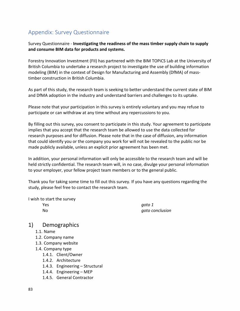
83
Appendix: Survey Questionnaire
Survey Questionnaire - Investigating the readiness of the mass timber supply chain to supply and consume BIM data for products and systems. Forestry Innovation Investment (FII) has partnered with the BIM TOPiCS Lab at the University of British Columbia to undertake a research project to investigate the use of building information modeling (BIM) in the context of Design for Manufacturing and Assembly (DfMA) of mass-timber construction in British Columbia. As part of this study, the research team is seeking to better understand the current state of BIM and DfMA adoption in the industry and understand barriers and challenges to its uptake. Please note that your participation in this survey is entirely voluntary and you may refuse to participate or can withdraw at any time without any repercussions to you. By filling out this survey, you consent to participate in this study. Your agreement to participate implies that you accept that the research team be allowed to use the data collected for research purposes and for diffusion. Please note that in the case of diffusion, any information that could identify you or the company you work for will not be revealed to the public nor be made publicly available, unless an explicit prior agreement has been met. In addition, your personal information will only be accessible to the research team and will be held strictly confidential. The research team will, in no case, divulge your personal information to your employer, your fellow project team members or to the general public. Thank you for taking some time to fill out this survey. If you have any questions regarding the study, please feel free to contact the research team. I wish to start the survey Yes goto 1 No goto conclusion 1) Demographics
1.1. Name 1.2. Company name 1.3. Company website 1.4. Company type
1.4.1. Client/Owner 1.4.2. Architecture 1.4.3. Engineering – Structural 1.4.4. Engineering – MEP 1.4.5. General Contractor

84
1.4.6. Specialty contractor – Structure 1.4.7. Specialty contractor – Other 1.4.8. Manufacturer/supplier 1.4.9. Other
1.5. Role 1.5.1. Architect 1.5.2. Engineer 1.5.3. Project manager 1.5.4. Project coordinator 1.5.5. BIM manager / coordinator 1.5.6. General director 1.5.7. Other
1.6. Has your organization worked with Mass Timber construction (incl. CLT panels, Glulam or other engineered timber product – “stick build” construction is not applicable)
1.6.1. Yes 1.6.2. No
1.7. Have you worked on projects where digital fabrication was used? (i.e. direct, electronic information flow between design and fabrication)
2) BIM 1.8. Has your company implemented building information modeling (BIM) (i.e. BIM tools,
technologies and/or processes) 1.8.1. Yes goto 3 1.8.2. No goto 4 1.8.3. What is BIM? goto 5
3) BIM - YES
1.9. How many projects has your firm completed using BIM? 1.10. How advanced/proficient would you say your organization is with BIM?
1.10.1. Novice – very basic skills, BIM used for 2D documents and visualization on a small number of projects
1.10.2. Beginner - BIM used for 2D documents, visualization and some analysis on a 1.10.3. Intermediate – BIM is used on most projects, but in a limited fashion 1.10.4. Advanced – BIM is used on all projects in an extensive fashion. 1.10.5. Expert – use of parametric design, complexe analysis, etc. on all projects
1.11. Have you ever used open standards for BIM (the Industry Foundation Classes as developed by buildingSMART)?
1.12. What have been the top three challenges in deploying BIM within your organization and / or projects?
1.13. What have been the top three benefits in deploying BIM within your organization and / or projects?
1.14. Have you used objects developed by third parties downloaded from the internet in your projects?

85
1.14.1. Yes 1.14.2. No
1.15. Would a regional or national BIM object library be useful to you or your organization in your day-to-day practice? ( A BIM object library is a cloud-based repository for BIM content that is produced and updated by manufacturers and suppliers)
1.15.1. Extremely useful 1.15.2. Very useful 1.15.3. Somewhat useful 1.15.4. Not very useful 1.15.5. Not useful at all
1.16. Would your organization be interested in participating or contributing content to such an object library?
1.16.1. Yes 1.16.2. No
4) BIM - NO
1.17. Do you believe your organization will adopt BIM within the next: 1.17.1. 6 months 1.17.2. 12 months 1.17.3. 24 months 1.17.4. 5 years 1.17.5. Never
1.18. What are the top three reasons why your organization hasn’t adopted BIM?
5) DfMA 1.19. Has your company been involved in projects or have adopted principals of
Design for Manufacturing and Assembly (DfMA) 1.19.1. Yes goto 6 1.19.2. No goto 7 1.19.3. What is DfMA?
6) DfMA - YES
1.20. How many projects has your firm completed using DfMA principals? 1.21. How advanced/proficient would you say your organization is with DfMA?
1.21.1. Novice – Basic DfMA principals applied to a very limited number of projects 1.21.2. Beginner – Basic DfMA principals applied to a small number of projects 1.21.3. Intermediate - – More advanced set of DfMA principals applied to a small
number of projects 1.21.4. Advanced – More advanced set of DfMA principals applied to a large number of
projects 1.21.5. Expert – DfMA principals deployed on all projects

86
1.22. What have been the top three challenges in deploying DfMA within your organization and / or projects?
1.23. What have been the top three benefits in deploying DfMA within your organization and / or projects?
7) DfMA - NO
1.24. Do you believe your organization will adopt DfMA principals within the next: 1.24.1. 6 months 1.24.2. 12 months 1.24.3. 24 months 1.24.4. 5 years 1.24.5. Never
1.25. What are the top three reasons why your organization hasn’t adopted DfMA principals?
8) Conclusion
Thank you for your time and input. If you wish to remain up-to-date on the progress of this research please provide us with your e-mail address.