building subdivision guidelines use of buildings to define ... · building subdivision guidelines...
TRANSCRIPT
Building Subdivision Guidelines Use of buildings to define boundaries

Contents
Introduction ...................................................................................................................................................................................................................................... 2 General.............................................................................................................................................................................................................................................. 2 Boundary location definitions ........................................................................................................................................................................................................ 3 Interior face....................................................................................................................................................................................................................................... 3 Regulation 10 (4) (a) Interior face examples – walls, vertical boundaries (defining horizontal extent).................................................................................. 4 Regulation 10 (4) (a) Interior face examples – floors/ceilings, horizontal boundaries (defining vertical extent) .................................................................. 4 Cross section – Regulation 10 (4) (a) Interior face horizontal boundaries (defining vertical extent) ..................................................................................... 6 Median (floor and ceiling) ............................................................................................................................................................................................................... 7 Median (wall, window, door, balustrade)....................................................................................................................................................................................... 8 Exterior face ................................................................................................................................................................................................................................... 12 Exterior face examples – walls – vertical boundaries (defining horizontal extent) ................................................................................................................ 12 Exterior face – floors/roofs – horizontal boundaries (defining vertical extent) ...................................................................................................................... 12 Some other location ...................................................................................................................................................................................................................... 15 Notations – Interior face................................................................................................................................................................................................................ 16 Notations – Median ........................................................................................................................................................................................................................ 18 Notations – Exterior/Interior face combination........................................................................................................................................................................... 18 Notations – Common Property..................................................................................................................................................................................................... 18 Notations – Hatching ..................................................................................................................................................................................................................... 18 Method of showing boundaries on a plan................................................................................................................................................................................... 19 Cross sections/elevations............................................................................................................................................................................................................. 21 Projections...................................................................................................................................................................................................................................... 21
Building Subdivision Guidelines – Use of buildings to define boundaries Page 2
Introduction Boundaries shown on a plan of subdivision become title boundaries when the plan is registered. A plan may utilise structure of a building to specify the location of boundaries. Boundaries fixed in this manner and depicted appropriately on the plan are referred to as building boundaries. On 8 October 2011 the Subdivision (Registrars Requirements) Regulations 2011 came into effect. Former Regulations 10, 11 and 12 of the Subdivision (Procedures) Regulations 2000 have been restructured into Regulations 10 and 11 of the Subdivision (Registrars Requirements) Regulations 2011. The Subdivision (Registrars Requirements) Regulations 2011 are aimed at narrowing the interpretation of building boundaries. This legislation is not retrospective and does not apply to plans of subdivision already registered. Plans of subdivision, staged (sec 37) plans, section 32 amendment plans and the like, signed on or after 8 October 2011, are affected. A transition period of 12 months up until 8 October 2012 will apply. These guidelines have been developed by Land Victoria as a guide to the preparation of plans of subdivision under the Subdivision (Registrars Requirements) Regulations 2011, where building boundaries are being used. General It must be clear to owners, purchasers, licensed surveyors, Land Victoria, relevant council officers, solicitors and owners corporation managers, where boundaries within a development are located. When a plan contains building boundaries, the plan must define the location of those boundaries by stating whether those boundaries lie along the ‘Interior face', ‘Exterior face’ or the ‘Median’ of the relevant building structure. See Regulations 10 (3) and Regulations 10 (4) (a),(b), (c) & (d). The position, within the structure, of boundaries defined in this manner will be set by application of the relevant regulation and no further definition is required. It is important to note that the context of the words ‘interior’ and ‘exterior’ when used to define the location of parcel boundaries is in ‘reference to a BUILDING’ (Regulation 10 Subdivision (Registrars Requirements) Regulations 2011. Alternately, Regulation 10 (3) (e) enables boundaries to be located in ‘some other location’ relative to the structure providing they can be fixed and are clearly described on the plan. This applies to parcel, easement and common property boundaries. Where a building boundary is defined in some other location as per Regulation 10 (3) (e), the description cannot be vague or ambiguous and must specify the location of the boundary with respect to the relevant part of the building structure. See ‘Some other location.’
Building Subdivision Guidelines – Use of buildings to define boundaries Page 3
Boundary location definitions Definitions of Interior face, Exterior face and Median building boundaries with respect to how they are applied to a number of common structure types have been adopted. These boundary location definitions are set out in Regulation 10 (4). The definitions and examples of how they are to be applied to various building structures are discussed below. Land Victoria understands that no one set of boundary definitions can be applied to all building subdivisions. Surveyors are asked to consider how the location of building boundaries, as shown on the plan they are preparing, is to be applied to the structure of the building being subdivided. In cases where the definitions are not appropriate or not applicable, notation(s) must be shown on the plan detailing how boundary definitions are to be applied to the building structure. Interior face REGULATION 10 (4). Unless otherwise specified on the plan the location of any building boundary defined as: (a) Interior face: lies along the interior face of any wall, floor (upper surface of elevated floor if any), ceiling (underside of suspended ceiling if any), window, door or balustrade of the relevant part of the building. Any internal coverings, water proof membranes and fixtures attached to walls, floors, and ceilings are included within the relevant parcel; Interior face building boundaries are generally adopted to exclude the parcel from ownership of the relevant building structure, e.g: if that part of the building structure is to be included into common property. If boundaries are to be adopted on the plan as interior face under this regulation, simply identify the boundaries to which it will apply and state they are ‘Interior face’ e.g.: Interior face: All boundaries………or……..Interior face: All floors and ceilings……..or……..Interior face: Boundaries marked ‘F’…….. etc. **Where horizontal boundaries (defining vertical extent) exist, appropriate cross section/s must be shown. Those boundaries will lie along the Interior face of any: Wall: being the internally exposed face of the permanent building structure excluding fixtures such as tiles, cupboards, splashbacks etc. Typically this would mean the internally exposed face of the plaster (if any), cement sheet or concrete render. Floor: being the upper face of the permanent building structure excluding fixtures such as tiles, carpet or floating floors. Typically this would mean the upper face of floorboards (if any), elevated floor (if any) or concrete slab. Ceiling: being the lower face of the permanent building structure excluding fixtures. Typically this would mean the lower face of the ceiling plaster or suspended ceiling. Window/door/balustrade: being the interior face of the relevant feature. Any internal coverings, water proof membranes and fixtures attached to walls, floors, and ceilings are included within the relevant parcel. See Regulation 10 (4) (a).

Regulation 10 (4) (a) Interior face examples – walls, vertical boundaries (defining horizontal extent)
Regulation 10 (4) (a) Interior face examples – floors/ceilings, horizontal boundaries (defining vertical extent)
Building Subdivision Guidelines – Use of buildings to define boundaries Page 4

Plan view – (Interior Face) – Vertical Boundaries (defining horizontal extent)
Building Subdivision Guidelines – Use of buildings to define boundaries Page 5

Cross section – Regulation 10 (4) (a) Interior face horizontal boundaries (defining vertical extent)
Building Subdivision Guidelines – Use of buildings to define boundaries Page 6
In the above examples, adopting interior face (as the exaggerated ‘actual location’ diagram confirms) indicates that the entire structure of the relevant wall, window, floor/ceiling etc. is contained in Common Property No.1.

Median (floor and ceiling) REGULATION 10 (4). Unless otherwise specified on the plan the location of any building boundary defined as: (b) Median: (floor and ceiling) lies within the middle of the building structure of any floor or ceiling of the relevant part of the building which defines a boundary. Any elevated floor or suspended ceiling does not form part of the building structure; Median building boundaries are adopted when ownership of the relevant building structure (boundary) is required to be split between the abutting proprietors. Horizontal median boundaries, being those which define the vertical extent of the parcel must be depicted by cross section (or acceptable notation in some circumstances). If boundaries are to be adopted on the plan as Median under this regulation, simply identify the boundaries to which it will apply and state they are ‘Median’. e.g.: Median: All boundaries ……….or……..Median: All floors and ceilings……….or……….Median: Boundaries marked ‘M’ etc. Those boundaries will lie along the centreline of what would be regarded as the core building structure of the relevant part of the building if they are floors, ceilings or similar (horizontal boundaries) and along the mid point between exposed surfaces of any wall (vertical boundaries) – see Regulation 10 (4) (c). For example, in the case where the relevant building structure is a concrete slab, the median boundary is within the centre of the slab, ignoring all material structures or fixtures which may lie above, below or be attached to the slab.
Similarly, in the case where the relevant building structure is joists, trusses or the like, the median boundary is within the centre of those joists or trusses, ignoring all material structures or fixtures which may lie above, below or be attached to them.
Building Subdivision Guidelines – Use of buildings to define boundaries Page 7
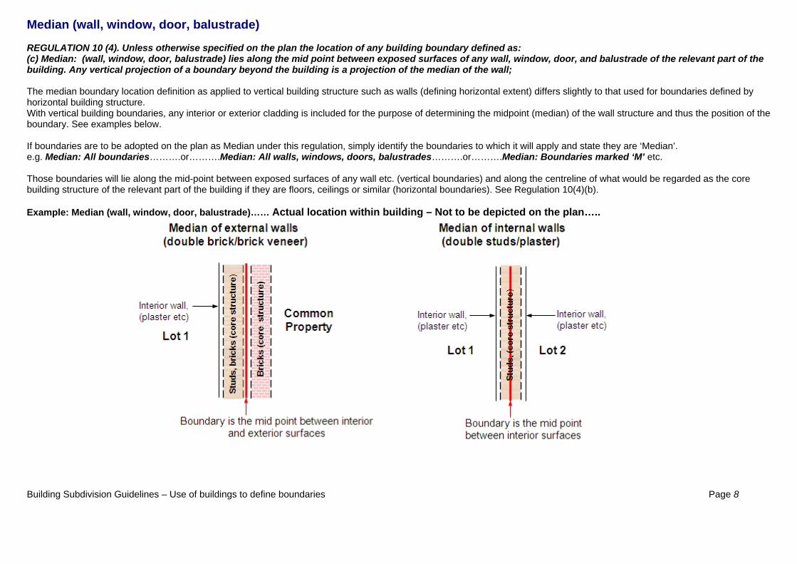
Median (wall, window, door, balustrade) REGULATION 10 (4). Unless otherwise specified on the plan the location of any building boundary defined as: (c) Median: (wall, window, door, balustrade) lies along the mid point between exposed surfaces of any wall, window, door, and balustrade of the relevant part of the building. Any vertical projection of a boundary beyond the building is a projection of the median of the wall; The median boundary location definition as applied to vertical building structure such as walls (defining horizontal extent) differs slightly to that used for boundaries defined by horizontal building structure. With vertical building boundaries, any interior or exterior cladding is included for the purpose of determining the midpoint (median) of the wall structure and thus the position of the boundary. See examples below. If boundaries are to be adopted on the plan as Median under this regulation, simply identify the boundaries to which it will apply and state they are ‘Median’. e.g. Median: All boundaries……….or……….Median: All walls, windows, doors, balustrades……….or……….Median: Boundaries marked ‘M’ etc. Those boundaries will lie along the mid-point between exposed surfaces of any wall etc. (vertical boundaries) and along the centreline of what would be regarded as the core building structure of the relevant part of the building if they are floors, ceilings or similar (horizontal boundaries). See Regulation 10(4)(b). Example: Median (wall, window, door, balustrade)…… Actual location within building – Not to be depicted on the plan…..
Building Subdivision Guidelines – Use of buildings to define boundaries Page 8

Application of Median to a typical single storey building….. Actual location within building – Not to be depicted on the plan
Building Subdivision Guidelines – Use of buildings to define boundaries Page 9

Multi storey plan example….
Building Subdivision Guidelines – Use of buildings to define boundaries Page 10

In the above examples, adopting median without further detailed notation (as the exaggerated ‘Actual location’ diagrams confirm) indicates that the ‘inner half’ of the wall on the ground storey lies within Lot 1. Above and below the structure of the wall the boundary is defined by a (vertical) projection of the said median of the wall. This example depicts the application of Median boundaries to a common form of building structure.
Building Subdivision Guidelines – Use of buildings to define boundaries Page 11

Exterior face REGULATION 10 (4).. Unless otherwise specified on the plan the location of any building boundary defined as: (d) Exterior Face: lies along the exterior face of any wall (and vertical projection thereof), door, window, balustrade, foundation, overhanging roof, eave or guttering of the relevant external part of the building. Any vertical projection of a boundary beyond the building is a projection of the exterior face of the wall. Exterior face building boundaries are generally adopted to include with the parcel, ownership of the relevant building structure including the roof, eaves and guttering (topmost/single storey where applicable). In the absence of building structure (e.g: above the roof/eave and below the foundation) the parcel boundary is taken to be a vertical projection of the exterior face of the wall. Both the plan (view) diagram and any cross section will show these building boundaries as being in the position of the exterior face of the wall and ignore any recesses that exist around windows and doors etc. and any protrusions that exist around eaves and foundations etc. See Regulation 11 (8). It must be noted that any reference to Exterior face refers to an exterior face ‘of the building’ not the lot. If boundaries are to be adopted on the plan as Exterior face under this regulation, simply identify the boundaries to which it will apply and state they are ‘Exterior face’ e.g: Exterior face: All boundaries……….or……….Exterior face: All walls, windows, doors, balustrades……….or……….Exterior face: Boundaries marked ‘E’ etc. Exterior face examples – walls – vertical boundaries (defining horizontal extent)
Building Subdivision Guidelines – Use of buildings to define boundaries Page 12

Exterior face – floors/roofs – horizontal boundaries (defining vertical extent) The use of Exterior face to define upper or lower boundaries is unusual and often implausible. Detailed cross section/s and notations would be required to precisely identify what part of the structure is being utilized as a building boundary. Plan view – (Exterior face) – vertical boundaries (defining horizontal extent)
Building Subdivision Guidelines – Use of buildings to define boundaries Page 13
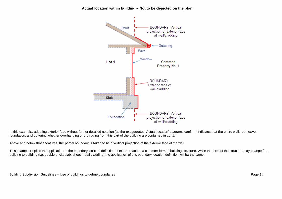
Actual location within building – Not to be depicted on the plan
In this example, adopting exterior face without further detailed notation (as the exaggerated ‘Actual location’ diagrams confirm) indicates that the entire wall, roof, eave, foundation, and guttering whether overhanging or protruding from this part of the building are contained in Lot 1. Above and below those features, the parcel boundary is taken to be a vertical projection of the exterior face of the wall. This example depicts the application of the boundary location definition of exterior face to a common form of building structure. While the form of the structure may change from building to building (i.e. double brick, slab, sheet metal cladding) the application of this boundary location definition will be the same.
Building Subdivision Guidelines – Use of buildings to define boundaries Page 14
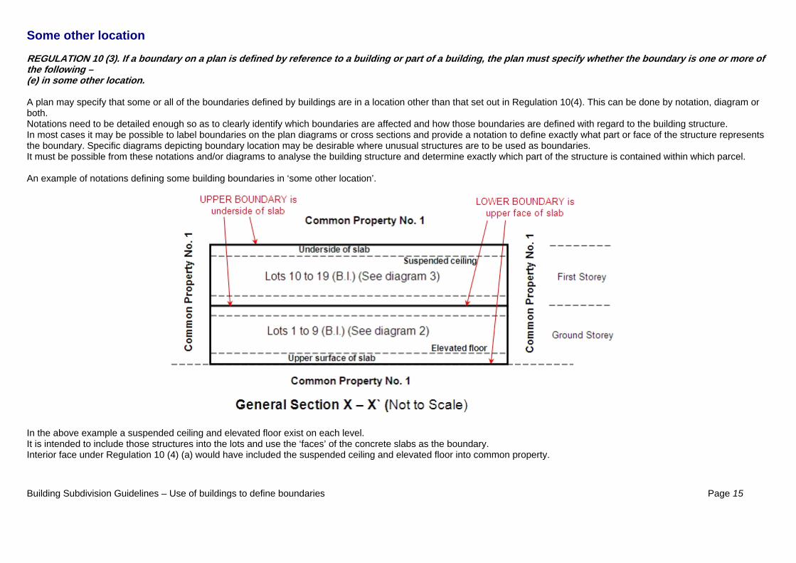
Some other location REGULATION 10 (3). If a boundary on a plan is defined by reference to a building or part of a building, the plan must specify whether the boundary is one or more of the following – (e) in some other location. A plan may specify that some or all of the boundaries defined by buildings are in a location other than that set out in Regulation 10(4). This can be done by notation, diagram or both. Notations need to be detailed enough so as to clearly identify which boundaries are affected and how those boundaries are defined with regard to the building structure. In most cases it may be possible to label boundaries on the plan diagrams or cross sections and provide a notation to define exactly what part or face of the structure represents the boundary. Specific diagrams depicting boundary location may be desirable where unusual structures are to be used as boundaries. It must be possible from these notations and/or diagrams to analyse the building structure and determine exactly which part of the structure is contained within which parcel. An example of notations defining some building boundaries in ‘some other location’.
Building Subdivision Guidelines – Use of buildings to define boundaries Page 15
In the above example a suspended ceiling and elevated floor exist on each level. It is intended to include those structures into the lots and use the ‘faces’ of the concrete slabs as the boundary. Interior face under Regulation 10 (4) (a) would have included the suspended ceiling and elevated floor into common property.
Building Subdivision Guidelines – Use of buildings to define boundaries Page 16
Notations that would be included on the plan… Subdivision (Registrars Requirements) Regulations 2011 apply. Location of boundaries defined by buildings – Interior Face: All boundaries unless otherwise specified Faces of concrete slab: All floors and ceilings. Common Property No. 1 is all the land in the plan except the lots and includes the structure of all walls, floors, ceilings, windows, doors, roofing etc which define boundaries except where indicated otherwise. Notations Notations – Interior face Selecting Interior face as the parcel boundary generally means the structure of the relevant wall, floor etc. is to be contained in common property. However, without further notation it is possible (particularly with an internal wall) to draw the conclusion that only one face of the wall is the boundary and that the wall may be contained in the abutting lot. Example 1 (below): Without further clarification it may be argued that in example 1 below, the Interior face within lot 1 is the only boundary present and the structure of the wall is contained in lot 2, or vice versa. Therefore further notations are required to be shown on the plan to eliminate this uncertainty by spelling out that the structure is included in the common property. If Interior face (Regulation 10(4)(a) is adopted each side of the specified structure may be a boundary**, in which case the structure and any cavities which lie between these boundaries will be common property. See examples set out below… Note: detail of these individual features are not depicted on the plan of subdivision; however, they must be considered as representing the actual location of the boundary and the extent of the parcel. ** In the case of Internal walls, further notation on the plan is required to clarify this. See notations and examples below….

Example 2 (below): Depicts what is usually intended as the parcel boundaries, i.e. that a boundary exists on the interior face of the wall of each lot and that the wall structure is contained in common property.
Where interior face (of both lots) is used to define the location of boundaries defined by buildings, and the structure of all walls, floors, ceilings, windows, doors and balustrades which define boundaries and all service installations or appurtenances of the building are within common property….. the following notations (or as much as is applicable) should be shown on the plan – ‘The structure of any wall, floor, ceiling, window, door, balustrade (other …..**) which define boundaries** are contained within Common Property No.# except where indicated otherwise**.’ or ‘Common Property No.# is all the land in the plan except the lots (and Roads and /or Reserves**) and includes the structure of all wall, floor, ceiling, window, door, balustrade (other**) which define boundaries** except where indicated otherwise** ’. ** = optional inclusion Boundaries set out in this manner and clarified with the above notations remove any confusion around ownership of the relevant building structure or the interpretation of ‘interior’ as applying to the building or the lot.
Building Subdivision Guidelines – Use of buildings to define boundaries Page 17

Building Subdivision Guidelines – Use of buildings to define boundaries Page 18
Notations – Median Where a plan specifies the median to define the location of boundaries, the said boundaries are the median of the relevant building structure (see Regulation 10 (4) (b) & (c) resulting in shared ownership of the relevant structure . While some notations may be necessary, there are no ‘generic’ notations relating to the building structure required to accompany ‘Median’. Notations – Exterior/Interior face combination Where a plan specifies Exterior face to define location of boundaries, the said boundaries are the exterior of the building, not exterior of the lot. There are no generic notations to accompany ‘Exterior face’, however if a plan uses exterior face, interior face of a building or a combination of both to define boundaries, the extent of the building must be clearly identifiable on the plan by either depiction or notation. i.e. The extent of the building includes those spaces defined by balconies, enclosed courtyards and the entrance to the underground car park (other…). Notations – Common Property REGULATION 10 (5) Subject to Sub regulation (4)(a), if all structures defining building boundaries and service installations or appurtenances not shown on the plan are within common property, a notation to that effect must be shown on the plan. Unless the extent of the common property is fully defined, plans containing common property must at least include a notation that states: ‘Common Property No.# is all the land in the plan except the lots (and Roads and /or Reserves**)’ Notations regarding building structure being contained in common property can be found under ‘Notation – Interior face’ above. The following notation (or as much as is relevant) may be required regarding additional service installations which are also to be included as part of the common property: ‘All internal columns, service ducts, pipe shafts and cable ducts, service installations (or other) within the building are deemed to be part of common property (...). The positions of these columns, service ducts, pipe shafts and cable ducts, service installations (or other**) may not have been shown on the diagrams contained herein’. ** = optional inclusion Notations – Hatching REGULATION 11 (4) If the position of hatching along a parcel boundary, easement boundary, or feature of a building is used to define the location of the structure of a building, an appropriate notation to this effect must be shown on the plan. Hatching may be used in a plan to assist in depicting the inclusion of structure into an adjacent parcel where that structure forms a boundary. The following notation (or as much as is relevant) must be shown on the plan: ‘Hatching within a parcel indicates that the relevant structure is contained within that parcel.’

Building Subdivision Guidelines – Use of buildings to define boundaries Page 19
This method may be particularly useful when:
some building structure defining boundaries lies within lots and some within common property. two separate walls ‘abut’ and the intention is to include the structure of each wall into the relevant lot. In this case the use of ‘median’ is not correct, and the description of
‘exterior face’ may be ambiguous. Providing the plan contains common property, a single line with hatching depicted on both sides would be the clearest representation of this.
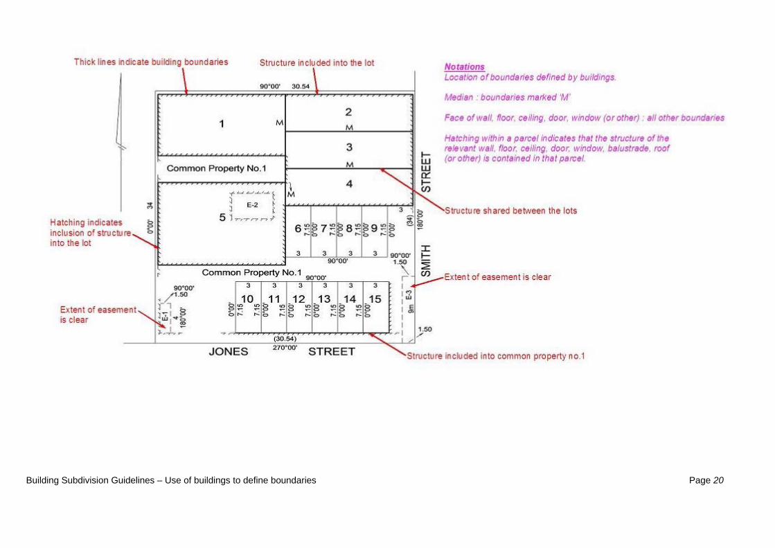
Method of showing boundaries on a plan REGULATION 11 (1) Subject to this regulation, a boundary must be shown on a plan by a continuous thin line. In the plan, all parcel boundaries must be shown by a continuous line unless the boundary is a projection shown in a cross section. (2) The depiction of any structure or feature of a building on a plan that does not constitute a parcel boundary must differ significantly to that of an easement on the same plan, unless the structure or feature is the easement. It is very important to avoid confusion between line work used to depict ‘non-boundary’ building structure, and the line work depicting an easement. Commonly these features are both shown with thin broken lines. However when both are to be depicted in the same plan, the line style for each must differ significantly so as to be easily understood. Where the structure forms an easement boundary, this should also be clear on the plan. (3) If the whole or part of a boundary is defined by a building or part of a building, the relevant boundaries must be identified on the plan by one or more of the following: (a) a thick continuous line (subject to this regulation); or (b) notation. Building boundaries are to be represented on the plan as thick continuous lines. This need not be stated on the plan. It may be acceptable to identify building boundaries by notation, such as ‘hatched continuous lines’ providing a notation stating such fact is shown on the plan. (4) If the position of hatching along a parcel boundary, easement boundary, or feature of a building is used to define the location of the structure of a building, an appropriate notation to this effect must be shown on the plan. Hatching along a boundary (within a parcel) may also be used to show that the structure which forms the boundary is included in that parcel, again, providing there is a notation on the plan to indicate this. This method is useful when it is intended to apply combinations of Interior face, Exterior face and Median building boundaries within the one plan, i.e: where some ‘boundary’ structure is shared, some is wholly contained in the lot and some is in common property. The need to make clear what is interior and what is exterior to the building in the diagram, is also redundant. It achieves very simply what would otherwise require detailed descriptive notations and numerous individual boundary labels. See following example…..
Building Subdivision Guidelines – Use of buildings to define boundaries Page 20

Building Subdivision Guidelines – Use of buildings to define boundaries Page 21
Cross sections/elevations A cross section is a ‘cut’ through a building and representative of only those lots directly affected by the ‘cut’. It must be clear from viewing the plan view diagram and cross section the full extent of the relevant parcel both vertically and horizontally. Where a ‘Typical Cross Section’ is used to define multiple parcels in the plan which may lie beyond the location of the ‘cut’, the cross section must be labelled as ‘Typical’ and the parcels to which it applies must be identified. When is a cross section required? REGULATION 11 (5) If parcels are located above or below each other or above or below parcels not in the plan, a cross section or diagram must be shown on the plan. Method of showing boundaries (Cross sections/elevations) (6) Unless defined by dimensions, a cross section must indicate the extent of relevant parcels by identifying the specific features of any buildings that define a boundary. Similar rules apply to the representation of boundaries in a cross section (or elevation) to those in plan view, whether defined by building structure or otherwise. Boundary Location Definitions (Interior, Exterior, Median) also apply to cross sections. (7) The information required by sub-regulations (5) and (6) may be approximately to scale. (8) Sub-regulations (5) and (6) do not include those parts of parcels located above or below each other created by the location of the boundary defined in regulation 10 (4). As is understood from regulation 10 (4), building boundaries may follow features of a wall such as windows, doors, eaves and foundations. These features may protrude inward or outward from the wall, however are not to be depicted in either plan view or cross section. Only the position of the wall as defining the boundary is to be shown. Projections REGULATION 11 (9) Projections of building boundaries on a cross section must be shown as thick broken lines and clarified by an appropriate notation if required. A parcel boundary can be defined by a projection of a building boundary. A projection can be of a vertical or horizontal building boundary shown in a cross section. (10) Only vertical or near vertical projections can be depicted in plan view. Vertical building boundaries (shown in plan view), such as a wall, cannot be projected horizontally under any circumstances. Vertical building boundaries can only be projected vertically (above or below). (11) Vertical or near vertical projections in plan view must be shown by thick continuous lines and clearly identified by notation. In a multi-level building subdivision, a plan view diagram of a particular level may depict a boundary as being defined by building structure, when in fact at that level no structure exists. This may occur when those boundaries are defined by a vertical projection of structure which lies on another level. This may cause confusion to registered proprietors and others.
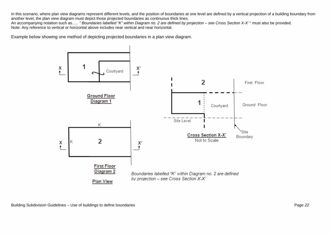
In this scenario, where plan view diagrams represent different levels, and the position of boundaries at one level are defined by a vertical projection of a building boundary from another level, the plan view diagram must depict those projected boundaries as continuous thick lines. An accompanying notation such as….. “ Boundaries labelled “K” within Diagram no. 2 are defined by projection – see Cross Section X-X’ “ must also be provided. Note: Any reference to vertical or horizontal above includes near vertical and near horizontal. Example below showing one method of depicting projected boundaries in a plan view diagram.
Building Subdivision Guidelines – Use of buildings to define boundaries Page 22

In a cross section……
thick broken lines are projections of boundaries defined by a building, as per Reg. 11 (9) lines which are not parcel boundaries may be shown as thin broken lines vinculums must not be used the arrows and cross section identifiers shown in plan view indicate the orientation and extent of the cross section cut notations should be used if required to further clarify a boundary or projection.
Building Subdivision Guidelines – Use of buildings to define boundaries Page 23

General Elevations A General Elevation is a ‘side view’ of a building and representative of all lots within the building where upper and lower boundaries are consistent throughout each level.
Building Subdivision Guidelines – Use of buildings to define boundaries Page 24

Vinculums Historically vinculums have been used in various plans and titles to ‘link’ parcels. Vinculums are no longer used for this purpose in plan diagrams. Each severed part of the one parcel in a plan of subdivision, must be described with the prefix “Pt” or the word Part. Vinculums are only used in plan view diagrams to represent a change in height within a parcel or part of a parcel. Vinculums are not used in cross sections.
Building Subdivision Guidelines – Use of buildings to define boundaries Page 25

Building Subdivision Guidelines – Use of buildings to define boundaries Page 26
Stairs Defining stairs in most cases should be fairly simple. For enclosed concrete stairs or similar, common methods of defining boundaries include underside of stairs, upper face of stairs or simply to include the structure “which defines boundaries” into common property… In all cases the relevant boundary should only be shown on the plan as a single inclined line and not depicted as individual steps or treads. Landings should be depicted.