bulletin 113 operation and maintenance · pdf fileoperation and maintenance instructions for...
TRANSCRIPT

OPERATION AND MAINTENANCE INSTRUCTIONS
For EVAPCO Induced Draft and Forced Draft Cooling Towers
Bulletin 113
®
For EVAPCO Authorized Parts and Service, Contact Your Local EVAPCO Representative or the Local Mr. GoodTower® Service Provider
www.evapco.com www.mrgoodtower.com
AT USS UT UBT REP LSTB LPT

2
Table of Contents
Introduction.................................................................................................................................................. 3Safety Precautions ...................................................................................................................................... 3Checklists..................................................................................................................................................... 4 Initial and Seasonal Start-Up Checklist ............................................................................................. 4 Maintenance Checklist ...................................................................................................................... 5 Seasonal Shut-Down Checklist ......................................................................................................... 7Fan System .................................................................................................................................................. 7 Fan Motor Bearings .......................................................................................................................... 7 Fan Shaft Bearings ........................................................................................................................... 7 Recommended Bearing Lubricants .................................................................................... 7 Fan Belt Adjustment .......................................................................................................................... 8 Fan and Motor Sheave Alignment ..................................................................................................... 8 Fan System Capacity Control ......................................................................................................... 10 Fan Motor Cycling ............................................................................................................ 10 Two Speed Motors ........................................................................................................... 10 Variable Frequency Drives ............................................................................................... 11Recirculated Water System Routine Maintenance .................................................................................12 Cold Water Basin ............................................................................................................................ 12 Suction Strainer Assembly .............................................................................................................. 12 Operating Water Levels .................................................................................................................. 12 Water Make Up Valve ..................................................................................................................... 13 Pressurized Water Distribution System ........................................................................................... 13 Drift Eliminator Orientation ............................................................................................... 15Water Treatment and Water Chemistry of the Recirculated Water System.......................................... 16 Bleed Off ......................................................................................................................................... 16 Biological Contamination ................................................................................................................ 16 Air Contamination ........................................................................................................................... 16 Water Chemistry Parameters .......................................................................................................... 17 Passivation of Galvanized Steel ..................................................................................................... 18 White Rust ....................................................................................................................... 18 Use of Soft Water ............................................................................................................................ 19 Use of Gray Water ...........................................................................................................19Stainless Steel ........................................................................................................................................... 19 Maintaining the Appearance of Stainless Steel ............................................................................... 20 Cleaning Procedures for Stainless Steel ........................................................................................ 20Cold Weather Operation ........................................................................................................................... 21Replacement Parts .................................................................................................................................... 25 Part Identifi cation Drawings ............................................................................................................ 26 AT/USS/UBT – 8’ and 8.5’ Wide Cells .............................................................................. 26 AT/USS/UBT – 12’ and 14’ Wide Cells ............................................................................. 27 ICT – All Models ............................................................................................................... 28 LPT – All Models .............................................................................................................. 29 LSTA – 4’ Wide Units ....................................................................................................... 30 LSTB – All Models ............................................................................................................ 31 REP – 8.5’ Wide Cells ...................................................................................................... 32 REP – 12’ Wide Cells ....................................................................................................... 33 UT – 8.5’ Wide Cells ........................................................................................................34 UT – 12’ and 14’ Wide Cells ............................................................................................. 35
3
Introduction
Congratulations on the purchase of your EVAPCO evaporative cooling unit. EVAPCO equipment is constructed of the highest quality materials and designed to provide years of reliable service when properly maintained.
Evaporative cooling equipment is often remotely located and periodic maintenance checks are often overlooked. It is important to establish a regular maintenance program and be sure that the program is followed. This bulletin should be used as a guide to establish a program. A clean and properly serviced unit will provide a long service life and operate at peak effi ciency.
This bulletin includes recommended maintenance services for unit start up, unit operation and unit shutdown and the frequency of each. Please note: the recommendations of frequency of service are minimums.Services should be performed more often when operating conditions necessitate.
Become familiar with your evaporative cooling equipment. Refer to the isometric drawings located on pages 26-35 for information on the arrangement of components in your equipment.
If you should require any additional information about the operation or maintenance of this equipment, contact your local EVAPCO representative. You may also visit www.evapco.com or www.mrgoodtower.com for more information.
Safety Precautions
Qualifi ed personnel should use proper care, procedures and tools when operating, maintaining or repairing this equipment in order to prevent personal injury and/or property damage. The warnings listed below are to be used as guidelines only.
WARNING: This equipment should never be operated without fan screens and access doors properly secured and in place.
WARNING: A lockable disconnect switch should be located within sight of the unit for each fan motor associated with this equipment. Before performing any type of service or inspection of the unit make certain that all power has been disconnected and locked in the “OFF” position.
WARNING: The top horizontal surface of any unit is not intended to be used as a working platform. No routine service work is required from this area.
WARNING: The recirculating water system may contain chemicals or biological contaminants including Legionella Pneumophila, which could be harmful if inhaled or ingested.Direct exposure to the discharge airstream and the associated drift generated during operation of the water distribution system and/or fans, or mists generated while cleaning components of the water system require respiratory protection equipment approved for such use by governmental occupational safety and health authorities.
4
Initial and Seasonal Start-Up Checklist
General 1. Verify that the overall installation refl ects the requirements of the installation guidelines found
in EVAPCO Bulletin 112 – Equipment Layout Manual.2. For multi-speed fan motors, verify that 30 second or greater time delays are provided for speed
changes when switching from high to low speed. Also check to see if interlocks are provided to prevent simultaneously energizing high and low speed.
3. Verify all safety interlocks work properly.4. For units operating with a variable frequency drive, make certain that minimum speed
requirements have been set. Check with VFD manufacturer for recommended minimum speeds.
5. Verify that the sensor used for fan sequencing and by-pass valve control is located downstream of the point where the by-pass water mixes with the condenser supply water,
if applicable.6. Verify that a water treatment plan has been implemented including passivation of galvanized
steel units. See “Water Treatment” section for more details.
BEFORE BEGINNING ANY MAINTENANCE, BE CERTAIN THAT THE POWER IS TURNED OFF AND THE UNIT IS PROPERLY LOCKED AND TAGGED OUT!
Initial and Seasonal Start-Up1. Clean and remove any debris, such as leaves and dirt from the air inlets.2. Flush the cold water basin (with the strainer screens in place) to remove any sediment or dirt.3. Remove the strainer screen, clean and reinstall.4. Check mechanical fl oat valve to see if it operates freely.5. Inspect water distribution system nozzles and clean as required. Check for proper orientation.
(This is not required at initial start-up. The nozzles are clean and set at the factory).6. Check to ensure drift eliminators are securely in place.7. Adjust fan belt tension as required.8. Lubricate fan shaft bearings prior to seasonal start-up. (This is not required at initial start-up.
The bearings have been lubricated at the factory prior to shipment).9. Turn the fan(s) by hand to insure it turns freely without obstructions.10. Visually inspect the fan blades. Blade clearance should be approximately ½” from tip of blade
to the fan cowl. The fan blades should be securely tightened to the fan hub.11. If any stagnant water remains in the system including “dead legs” in the piping, the unit must
be disinfected prior to the fans being energized. Please refer to ASHRAE Guideline 12-2000 and CTI Guideline WTP-148 for more information.
12. Fill the cold water basin manually up to the overfl ow connection.
After the unit has been energized, check the following:1. Adjust mechanical fl oat valve as required. 2. Unit basin should be fi lled to the proper operating level. See “Recirculating Water System
– Operating Levels” section for more details.3. Verify fan is rotating in proper direction.4. Measure voltage and current on all three power leads. The current must not exceed the
motor nameplate full load amp rating. 5. Adjust bleed valve to proper fl ow rate. Maximum bleed off is 3 US GPM per 100 tons.

5
MAINTENANCECHECKLIST
PROCEDURE JAN FEB MAR APR MAY JUN JUL AUG SEP OCT NOV DEC
1. Clean pan strainer – monthly or as needed
2. Clean and flush pan** – quarterly or as needed
3. Check bleed-off valve to make sure it is operative – monthly
4. Check operating level in pan and adjust float valve if necessary – monthly
5. Check water distribution system and spray pattern – monthly
6. Check drift eliminators – quarterly
7. Check the fan blades for cracks, missing balancing weights, and vibrations - quarterly
8. Lubricate fan shaft bearings* - every 1000 hours of operation or every three months
9. Lubricate fan motor bearings – see mfg’s instructions. Typically for non-sealed bearings, every 2-3 years
10. Check belt tension and adjust – monthly
11. Sliding motor base – Inspect and grease – annually or as needed
12. Check fan screens, inlet louvers and fans. Remove any dirt or debris - monthly
13. Inspect and clean protective finish – annually
-Galvanized: scrape and coat with ZRC
-Stainless: clean and polish with a stainless steel cleaner.
14. Check water quality for biological contamination. Clean unit as needed and contact a water treatment company for recommended water treatment program** – regularly
OPTIONAL ACCESSORIES:
1. Gear Reducer – Check oil level with unit stopped – 24 hours after start-up & monthly
2. Gear Reducer/Piping – Do visual inspection for oil leaks, auditory inspection for unusual noises and vibrations – monthly
3. Gear Reducer - Replace oil – semi-annually
4. Oil Pump – Do visual inspection for leaks and proper wiring – monthly
5. Gear Reducer/Coupling – Check alignment of the system – 24 hours after start-up & monthly
*See maintenance manual for start-up instructions and lubrication recommendations
** Cooling Towers must be cleaned on a regular basis to prevent the growth of bacteria including Legionella Pneumophila
®

6
MAINTENANCECHECKLIST
PROCEDURE JAN FEB MAR APR MAY JUN JUL AUG SEP OCT NOV DEC
6. Coupling/Shaft – Inspect flex elements and hardware for tightness, proper torque & crack/deterioration – monthly
7. Heater Controller – Inspect controller and clean probe ends – quarterly
8. Heater – Inspect junction box for loose wiring and moisture – one month after start-up and semi-annually
9. Heater – Inspect elements for scale build-up – quarterly
10. Electronic Water Level Controller – Inspect junction box for loose wiring and moisture – semi-annually
11. Electronic Water Level Controller – Clean probe ends of scale build-up – quarterly
12. Electronic Water Level Controller –Clean inside the standpipe – annually
13. Solenoid Make-up Valve – Inspect and clean valve of debris – as needed
14. Vibration Switch (mechanical) – Inspect enclosure for loose wiring and moisture – one month after start-up and monthly
15. Vibration Switch – Adjust the sensitivity – duringstart-up and annually
16. Sump Sweeper Piping – Inspect and clean piping of debris – semi-annually
17. Water Level Indicator – Inspect and clean – annually
DURING IDLE PERIODS:
1. Few Weeks: Run gear reducer for 5 minutes – weekly
2. Several Weeks: Completely fill gear reducer with oil. Drain to normal level prior to running.
3. One Month or longer: Rotate motor shaft/fan 10 turns– bi-weekly
4. One Month or longer: Megger test motor windings – semi-annually
®

7
Seasonal Shut-Down Checklist
When the system is to be shut down for an extended period of time, the following services should be performed.
1. The evaporative cooling unit should be drained.2. The cold water basin should be fl ushed and cleaned with the suction strainer
screens in place.3. The suction strainer screens should be cleaned and re-installed.4. The cold water basin drain should be left open.5. The fan shaft bearings and motor base adjusting screws should be lubricated.6. The water make up valve needs to be closed. All water make-up piping needs to
be drained, if not heat traced and insulated.7. The fi nish of the unit should be inspected. Clean and refi nish as required.8. The fan bearings and motor bearings need to be turned at least once a month by
hand. This can be accomplished by making sure the unit’s disconnect is locked and tagged out, and grasping the fan assembly, rotating it several turns.
Fan System
The fan systems of both centrifugal and axial driven units are rugged, however, the fan system must be checked regularly and lubricated at the proper intervals. The following maintenance schedule is recommended.
Fan Motor BearingsEVAPCO evaporative cooling units use either a T.E.A.O. (Totally Enclosed Air Over) or a T.E.F.C. (Totally Enclosed Fan Cooled) fan motor. These motors are built to “Cooling Tower Duty” specifi cations. They are supplied with permanently lubricated bearings and special moisture protection on the bearings, shaft and windings. After extended shut-downs, the motor should be checked with an insulation tester prior to restarting the motor.
Fan Shaft Ball BearingsLubricate the fan shaft bearings every 1,000 hours of operation or every three months for induced draft units. Lubricate the fan shaft bearings every 2,000 hours of operation or every six months for forced draft units. Use any of the following synthetic waterproof, polyurea inhibited greases which are suitable for operation between -20°F and 350°F. (For colder operating temperatures, contact the factory).
Mobil – Polyrex EM Chevron - SRI
Feed grease slowly into the bearings or the seals may be damaged. A hand grease gun is recommended for this process. When introducing a new grease, all grease should be purged from the bearings.
All EVAPCO units are supplied with extended grease lines to allow easy lubrication of the fan shaft bearings.

8
Unit Description Location of Lube Line Fittings
Induced Draft Units – 8’ wide Located just beside the fan casing access door
Induced Draft Units – 8.5’ wide Located just beside the fan casing access door
Induced Draft Units – 12’ wide Located inside the fan casing access door
Induced Draft Units – 17’ wide Located just beside the fan casing access door
Induced Draft Units – 14’ wide Located inside the fan casing access door
Induced Draft Units – 24’ wide Located inside the fan casing access door
Induced Draft Units – 28’ wide Located inside the fan casing access door
LSTB Forced Draft Units Located on the front of the unit
LPT Forced Draft Units Located on the front of the unit
Table 1 – Location of Grease Lube Line Fittings for Belt Driven UnitsPlease note, the removal of the fan screens is not necessary on forced draft units to access the extended lube line fi ttings.
Fan Shaft Sleeve Bearings – (4’ wide LSTA units only)Lubricate the intermediate sleeve bearing(s) before unit start up. The reservoir should be checked several times during the fi rst week to ensure that the oil reserve is brought to full capacity. After the fi rst week of operation, lubricate the bearing(s) every 1,000 hours of operation or every three months (whichever occurs fi rst). High temperatures or poor environmental conditions may necessitate more frequent lubrication. The oil reservoir consists of a large felt packed cavity within the bearing housing. It is not necessary to maintain the oil level within the fi ller cup.
Use one of the following industrial grade, non-detergent mineral oils. Do not use a detergent based oil or those designated heavy duty or compounded. Different oils may be required when operating at temperatures below 30°F continuously. Table 2 provides a short list of approved lubricants for each temperature range. Most automotive oils are detergent based and may not be used. Detergent oils will remove the graphite in the bearing sleeve and cause bearing failure.
Ambient Temp Texaco Drydene Exxon
30°F to 100°F Regal R&O 220 Paradene 220 Terrestic 220
-25°F to 30°F Capella WF 32 Refrig. Oil 3G ------------------
Table 2 - Sleeve Bearing Lubricants
All bearings used on EVAPCO equipment are factory adjusted and self aligning. Do not disturb bearing alignment by tightening the sleeve bearing caps.
Fan Belt AdjustmentThe fan belt tension should be checked at start up and again after the fi rst 24 hours of operation to correct for any initial stretch. To properly adjust the belt tension, position the fan motor so that the fan

9
belt will defl ect approximately ½” when moderate pressure is applied midway between the sheaves. Figure 1 and Figure 2 show two ways to measure this defl ection. Belt tension should be checked on a monthly basin. A properly tensioned belt will not “chirp” or “squeal” when the fan motor is started.
Figure 1 – Method 1 Figure 2 – Method 2
On induced draft belt driven units provided with externally mounted motors (8, 8.5 and 17 foot wide units), Figure 3, and LSTB forced draft units, Figure 4, both J-type adjustment bolts on the adjustable motor base should have an equal amount of exposed thread for proper sheave and belt alignment.
Figure 3 – Externally Mounted Motors Figure 4 – LSTB Externally Mounted Motor
Figure 5 – Internally Mounted Motors
On induced draft belt driven units with internally mounted motors (12, 14, 24 and 28 foot wide units), Figure 5, and LPT units, Figure 6, a motor adjustment tool is provided. The tool will be found on the adjustment nut. To use, place the hex end over the adjustment nut. Tension the belt by turning the nut counterclockwise. When the belts are properly tensioned, tighten the lock nut.

10
Figure 6 – LPT Motor Adjustment
Direct drive fan units do not require any adjustment.
Fan System — Capacity Control
There are several methods for capacity control of the evaporative cooling unit. Methods include: Fan motor cycling, the use of two speed motors and the use of variable frequency drives (VFD’s).
Fan Motor CyclingFan Motor Cycling requires the use of a single stage thermostat which senses the water temperature. The contacts of the thermostat are wired in series with the fan motor’s starter holding coil.
Fan Motor Cycling is often found to be inadequate where the load has a wide fl uctuation. In this method, there are only two stable levels of performance: 100% of capacity when the fan is on and approximately 10% of capacity when the fan is off. Please note, rapid cycling of the fan motors can cause the fan motor to overheat. Controls should be set to only allow a maximum of six (6) start/stop cycles per hour.
Two Speed MotorsThe use of a two speed motor provides an additional step of capacity control when used with the fan cycling method. The low speed of the motor will provide 60% of full speed capacity.
Two speed capacity control systems require not only a two speed motor, but a two stage thermostat and the proper two speed motor starter. The most common two speed motor is a single winding type. This is also known as a consequent pole design. Two speed two winding motors are also available. All multi-speed motors used in evaporative cooling units should be variable torque design.
It is important to note that when two speed motors are to be used, the motor starter controls must be equipped with a decelerating time delay relay. The time delay should be a minimum of a 30 second delay when switching from high speed to low speed.

11
Sequence of Operation for Two Fan Units with Two Speed Motors During Peak Load1. Both fan motors on full speed – full water fl ow over both cells2. One fan motor on high speed, one fan motor on low speed – full water fl ow over both cells3. Both fan motors on low speed – full fl ow over both cells4. One fan motor on low speed, one fan motor off – full water fl ow over both cells5. Both fan motors off – full water fl ow over both cells6. Both fan motors off – full single cell fl ow through one cell
Variable Frequency DrivesThe use of a variable frequency drive (VFD) provides the most precise method of capacity control. A VFD is a device that converts a fi xed AC voltage and frequency and changes it into an AC adjustable voltage and frequency used to control the speed of an AC motor. By adjusting the voltage and frequency, the AC induction motor can operate at many different speeds.
The use of VFD technology can also benefi t the life of the mechanical components with fewer and smoother motor starts and built in motor diagnostics. VFD technology has particular benefi t on evaporative cooling units operating in cold climates where airfl ow can be modulated to minimize icing and reversed at low speed for de-icing cycles. Applications using a VFD for capacity control must also use an inverter duty motor built in compliance with NEMA standard MG-1. This is an available option from EVAPCO. The standard fan motors supplied by EVAPCO are not intended for use with VFD’s.
The type of motor, manufacturer of the VFD, motor lead lengths (between the motor and the VFD), conduit runs and grounding can dramatically affect the response and life of the motor. The motor lead length restrictions vary with the motor vendor. Regardless of motor supplier, minimizing motor lead length between the motor and the drive is good practice.
Sequence of Operation for Multi-fan Units with a VFD During Peak Load1. The VFDs should all be synchronized to speed up and slow down uniformly.2. The VFDs need to have a pre-set shutoff to prevent water temperatures
from becoming too cold and to prevent the drive from trying to turn the fan at near zero speed.
3. Operating below 25% of motor speed achieves very little return in fan energy savings and capacity control. Check with your VFD supplier if operating below 25% is possible.
For more details on the use of variable frequency drives, please request a copy of EVAPCO’s Engineering Bulletin 39.

12
Recirculated Water System – Routine Maintenance
Suction Strainer in Cold Water BasinThe pan strainer should be removed and cleaned monthly or as often as necessary. The suction strainer is the fi rst line of defense in keeping debris out of the system. Make certain that the strainer is properly located over the pump suction, alongside the anti-vortexing hood.
Figure 7 – Single Strainer Assembly Figure 8 – Dual Strainer Assembly
Cold Water BasinThe cold water basin should be fl ushed out quarterly, and checked monthly or more often if necessary, to remove any accumulation of dirt or sediment which normally collects in the basin. Sediment can become corrosive and cause deterioration of basin materials. When fl ushing the basin, it is important to keep the suction strainers in place to prevent any sediment from entering the system. After the basin has been cleaned, the strainers should be removed and cleaned before refi lling the basin with fresh water.
Operating Level of Water in Cold Water BasinThe operating level should be checked monthly to make sure the water level is correct. Refer to Table 3 for unit specifi c levels.
Model Number OperatingDepth*
ICTICT
3-634-54
throughthrough
3-934-912
6”7”
UBTUBT
8-56B24-524B
throughthrough
24-918B24-936B
9”11”
AT/USS/UTAT/USS/UT
19-56424-024
throughthrough
224-918428-948
9”11”
REP/UT 217-111 through 224-920 9”
LSTALSTBLSTB
4-61511210112
throughthroughthrough
4-1858P53610636
9”9”
13”
LPT 316 through 8812 8”
* Measured from lowest point on basin fl oor.
Table 3 Recommended Operating Water Level

13
At initial start up or after the unit has been drained, the unit must be fi lled to the overfl ow level. Overfl ow is above the normal operating level and accommodates the volume of water normally in suspension in the water distribution system and some of the piping external to the unit.
The water level should always be above the strainer. Check by running the pump with the fan motors off and observing the water level through the access door or remove the air inlet louver.
Water Make Up ValveA mechanical fl oat valve assembly is provided as standard equipment on the evaporative cooling unit (unless the unit has been ordered with an optional electronic water level control package or the unit is arranged for remote sump operation). The make up valve is easily accessible from outside the unit through the access door or removable air inlet louver. The make up valve is a bronze valve connected to a fl oat arm assembly and is activated by a large foam fi lled plastic fl oat. The fl oat is mounted on an all thread rod held in place by wing nuts. The water level in the basin is adjusted by repositioning the fl oat and all thread using the wing nuts. Refer to Figure 9 for details.
Figure 9 – Mechanical Water Make Up Valve
The make up valve assembly should be inspected monthly and adjusted as required. The valve should be inspected annually for leakage and if necessary, the valve seat should be replaced. The make up water pressure should be maintained between 20 and 50 PSIG.
Pressurized Water Distribution SystemsAll EVAPCO cooling towers are supplied with wide orifi ce water diffusers. The water distribution system should be checked monthly to make sure it is operating properly. Always check the spray system with the pump on and the fans off (locked and tagged out).
On forced draft units (LSTB, LPT and LSTA models), remove one or two eliminator sections from the top of the unit and observe the operation of the water distribution system.
On induced draft units (AT, USS, REP, UT, UBT and ICT models), lifting handles are provided on several sections of eliminators within reach of the access door. Eliminators can be easily removed from outside of the unit to observe the water distribution system. The diffusers are essentially non-clogging and should seldom need cleaning or maintenance.

14
If the water diffusers are not functioning properly, it is a sign that the suction strainer has not beenworking properly and that foreign matter or dirt has accumulated in the water distribution pipes. Thenozzles can be cleared by taking a small pointed probe and moving it back and forth in the diffuseropening.
If an extreme build up of dirt or foreign matter occurs, remove the end cap in each branch to fl ush thedebris from the header pipe. The spray branches and header can be removed for cleaning, but shouldonly be done if absolutely necessary.
After the water distribution system has been cleaned, the suction strainer should be checked to makesure it is in good operating condition and positioned properly so that cavitation or air entrapment doesnot occur.
When inspecting and cleaning the water distribution system, always check that the orientation of thewater diffusers is correct as shown below for LSTB, LPT, LSTA, ICT and UBT models in Figure 10and as shown in Figure 11 for AT, USS, REP and UT models. The top of the EVAPCO logo on thenozzle is parallel with the top of the water distribution pipe.
THREADED END CAP
Figure 10 - Water Distribution
Figure 11 - Water Distribution
15
Drift Eliminators Induced Draft Units (AT, USS, REP, UT, UBT and ICT Models)Orientation of the eliminator sections on induced draft units is not critical. Note though, that the eliminator sections must fi t tightly together within the fan section of the unit.
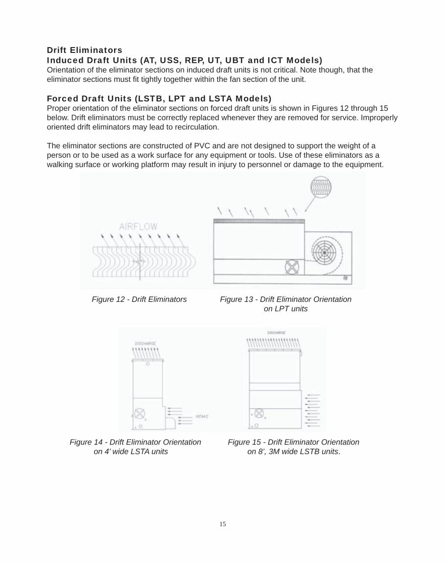
Forced Draft Units (LSTB, LPT and LSTA Models)Proper orientation of the eliminator sections on forced draft units is shown in Figures 12 through 15 below. Drift eliminators must be correctly replaced whenever they are removed for service. Improperly oriented drift eliminators may lead to recirculation.
The eliminator sections are constructed of PVC and are not designed to support the weight of a person or to be used as a work surface for any equipment or tools. Use of these eliminators as a walking surface or working platform may result in injury to personnel or damage to the equipment.
Figure 12 - Drift Eliminators Figure 13 - Drift Eliminator Orientation on LPT units
Figure 14 - Drift Eliminator Orientation Figure 15 - Drift Eliminator Orientation on 4’ wide LSTA units on 8’, 3M wide LSTB units.

16
Water Treatment and Water Chemistry of the Recirculated Water System
It is recommended that a qualifi ed water treatment company be contacted to design a water treatment protocol specifi cally for equipment and location.
Evaporative cooling equipment rejects heat by evaporating a portion of the recirculated water and discharging it into the atmosphere in the hot, saturated discharge air. As the water evaporates, it leaves behind all the mineral content and impurities. If the water chemistry is not controlled properly, the residuals may become concentrated and lead to corrosion, scaling, sludge build up and biological fouling. Corrosion would be identifi ed as red rust on steel components or white rust on galvanized steel. Corrosion will adversely affect the longevity of the tower. Scale reduces heat transfer effi ciency and system effi ciency, while scale and sludge can both lead to under deposit corrosion. Biological fouling such as slime and algae may reduce the unit’s heat transfer, promote corrosion and possibly harbor pathogens such as Legionella Pneumophila.
Bleed OffAs a minimum, to avoid the build up of residuals in the water distribution system, water must be drained out of the system at a rate large enough to the control the system water chemistry. The maximum amount of bleed is equal to the rate of evaporation.
Open cooling towers need to have a bleed line installed on the discharge side of the system pump. A metering device and globe valve should also be provided. The metering device is used to determine the bleed water volume. The globe valve is used to regulate fl ow.
Another method to remove residuals is to use a conductivity controlled blowdown device. This method should also be considered for water savings.
Biological ContaminationWater quality should be checked regularly for biological contamination. If biological contamination is detected, a more aggressive water treatment and mechanical cleaning program is required. The water treatment program should be performed in conjunction with a qualifi ed water treatment company. It is important that all internal surfaces be kept clean of accumulated dirt or sludge. In addition, the drift eliminators should be kept in good operating condition to minimize water from exiting the evaporative cooling unit in the discharge air.
To minimize the risk of biological contamination, at initial start up or after an extended shut down, it is recommended that the entire system (cooling tower, system piping, heat exchanger, etc.) be properly treated. Clean all debris such as leaves and dirt from the unit. Completely fi ll the basin to the overfl ow level with fresh water. Initiate a biocide water treatment or shock treatment program prior to operating the unit. It is preferable that all such procedures be conducted or supervised by a water treatment specialist.
Air ContaminationIf the unit is located in an area where there are contaminents such as: chemical fumes, industrial smoke, salt or heavy dust, the impurities in the air will be washed out in the recirculated water and may cause scaling, corrosion or accelerated biological growth. It is important not to locate the unit next to smokestacks, discharge ducts, vents, fl ue gas exhausts, etc. because the unit will draw in these fumes which may lead to extremely corrosive conditions. It is also important to locate the unit
17
away from the building’s fresh air intakes to prevent any drift or other unit discharge from entering the building’s air system. The quantity of impurities in the air will determine the frequency of the maintenance program. Bleeding off the impurities will help, but if there are any signs of corrosion, scaling or biological growth, the qualifi ed water treatment specialist should be contacted.
Water Chemistry ParametersA proper water treatment program is an essential part of routine maintenance to ensure the safe operation and longevity of this unit. A water treatment company familiar with local water conditions should be consulted.
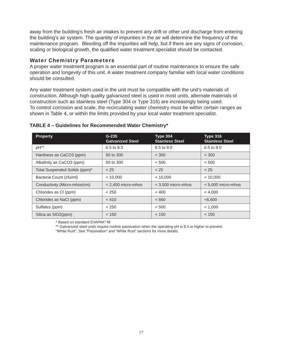
Any water treatment system used in the unit must be compatible with the unit’s materials of construction. Although high quality galvanized steel is used in most units, alternate materials of construction such as stainless steel (Type 304 or Type 316) are increasingly being used.To control corrosion and scale, the recirculating water chemistry must be within certain ranges as shown in Table 4, or within the limits provided by your local water treatment specialist.
TABLE 4 – Guidelines for Recommended Water Chemistry*
Property G-235 Galvanized Steel
Type 304 Stainless Steel
Type 316 Stainless Steel
pH** 6.5 to 8.3 6.5 to 9.0 6.5 to 9.0
Hardness as CaCO3 (ppm) 50 to 300 < 300 < 300
Alkalinity as CaCO3 (ppm) 50 to 300 < 500 < 500
Total Suspended Solids (ppm)* < 25 < 25 < 25
Bacteria Count (cfu/ml) < 10,000 < 10,000 < 10,000
Conductivity (Micro-mhos/cm) < 2,400 micro-mhos < 3,500 micro-mhos < 5,000 micro-mhos
Chlorides as Cl (ppm) < 250 < 400 < 4,000
Chlorides as NaCl (ppm) < 410 < 660 <6,600
Sulfates (ppm) < 250 < 500 < 1,000
Silica as SiO2(ppm) < 150 < 150 < 150
* Based on standard EVAPAK® fi ll** Galvanized steel units require routine passivation when the operating pH is 8.3 or higher to prevent “White Rust”. See “Passivation” and “White Rust” sections for more details.

18
If a chemical water treatment program is used, the chemicals selected must be compatible with the unit materials of construction as well as other materials used in the system. The chemicals must be accurately metered and concentrations properly controlled. Chemicals should be introduced through automatic feeders at a point in the system where total mixing can occur before reaching the evaporative cooling equipment. Chemicals should never be batch fed directly into the unit’s basin or water distribution system. The use of acid should be avoided. If acid cleaning is required, only inhibited acids recommended for use with the unit’s materials of construction should be used.
Passivation of Galvanized SteelPassivation is the formation of a protective zinc carbonate layer on galvanized steel. The zinc carbonate layer protects the galvanized surface by sacrifi cing itself slowly over time. This layer can be diminished by walking on the surface or by pressure washing.
Heavy mill galvanizing provides an excellent corrosion resistant barrier for the substrate steel on an evaporative cooling unit. The zinc fi nish is a reactive metal which acts as a sacrifi cial anode to protect the steel substrate. Units that are operated within the recommended pH levels of 6.5 to 8.3 and are passivated allow a surface barrier of non-porous zinc carbonate and zinc hydroxide to form which prevents rapid galvanic corrosion. This basic zinc carbonate barrier must be allowed to form in order to provide maximum protection for the mill galvanized steel.
Steel mills producing galvanized steel perform a passivation wash after processing the steel. Thismill applied passivation is only a temporary passivation program. The unit must be passivated during the unit start up phase and must be part of the water treatment program. Passivation of the galvanized steel surface is critical to prevent the formation of “white rust” and to extend the life of evaporative cooling equipment.
To prevent the formation of “white rust” (porous zinc carbonate cells), the interior of the unit must be passivated during start up and monitored periodically as part of the water treatment program. A qualifi ed water treatment program should be designed to inhibit zinc corrosion while maintaining chemical concentrations within recommended levels. Since re-passivation may be necessary during normal operation, the water treatment program should be continually monitored.
The passivation program should operate for a period of 45 to 60 days. The pH of the circulating water must be between 7.0 and 8.0; hardness measured as CaCO3 should be between 100-300 ppm; and alkalinity measured as CaCO3 should be between 100-300 ppm.
If white zinc deposits form on the galvanized steel surfaces after the pH is returned to normal operating levels, it may be necessary to repeat the passivation process. These deposits should not be removed with pressure washing, wire brushing or by any other mechanical means. See Section titled “White Rust” for more information.
White RustWhite rust is defi ned as “the rapid formation of non-protective zinc carbonate cells on the surface of galvanized steel”. These deposits appear as white powdery cells and are considered to be a zinc corrosion by-product. These cells are porous and allow continued corrosion of any non-passivatedgalvanized steel surface. This type of corrosion is most prevalent in the wetted areas of evaporative cooling products. Water chemistry that promotes the formation of “white rust” includes:
19
1. pH levels greater than 8.32. Calcium hardness as CaCO3 less than 50 ppm3. Anions of sulfates, chlorides and nitrates greater than 250 ppm4. Soft water with calcium hardness (CaCO3) less than 50 ppm combined with
a high alkalinity greater than 300 ppm (CaCO3) and a pH greater than 8.3
It should be noted that not all white deposits found on galvanized steel surfaces are due to white rust. As a result, it is imperative to determine the inorganic content of the deposit. The deposits may be calcium based and not zinc based.
For more information, please request a copy of EVAPCO’s Engineering Bulletin 36 on White Rust.
Soft WaterThe use of soft water with a galvanized steel unit is not recommended. Soft water is corrosive to galvanized steel.
In general, both Type 304 and Type 316 stainless steel exhibit good corrosion resistance to soft water. However, soft water is usually generated from water softeners which typically use a brine solution (concentrated salt water) to regenerate. After regeneration, this brine is fl ushed. If the softener is out of adjustment, not all the brine will fl ush out and this salt (NaCl) will be carried out with the fi nished water. This poses the risk of high chlorides in the unit’s recirculated water. Type 304 stainless steel is susceptible to corrosion at high chloride levels. Type 316 stainless steel is more resistant to this corrosion.
Gray WaterGray water is broadly defi ned as any water that has been used in a home or commercial environment, except water from toilets. The use of gray water can be considered as long as the water chemistry conforms to the parameters found in the Water Treatment section of this bulletin and understanding the risks of fouling or biological contamination when gray water is used. Gray water should be avoided unless all of the risks are understood and taken into account.
Stainless Steel
Stainless steel is the most cost effective material of construction available to extend the life of an evaporative cooling unit.
The stainless steel sheet material utilized by EVAPCO is Type 304 and Type 316 with a No. 2B unpolished fi nish. Type 304 stainless steel is a basic chromium-nickel austenitic stainless steel and is suitable for a wide range of applications. It is readily available throughout the world and is easy to form during the fabrication process. Type 316 stainless steel offers more corrosion resistance than Type 304 due to the addition of molybdenum and a higher nickel content, which provides greater resistance to pitting and crevice corrosion in the presence of chlorides. As a result, Type 316 stainless steel is desirable in heavy industrial, marine environments and where make up water quality requires it.
Stainless steel provides its superior corrosion resistance by developing a surface fi lm of chromium oxide during the manufacturing process. In order to ensure maximum corrosion protection, stainless steel must be kept clean and have an adequate supply of oxygen to combine with the chromium in the stainless steel to form “chromium-oxide”, a protective passivation layer. The protective layer of chromium-oxide develops during routine exposure to the oxygen content in the

20
atmosphere. This occurs during the milling process and continuously as the stainless is formed and shaped for its fi nal use.
Maintaining the Appearance of Stainless SteelIt is a common misconception that stainless steel is stain and rust proof, making surface maintenance not required at all. This is simply not true. Like mill galvanized steel, stainless steel is most effective when kept clean. This is especially true when located in atmospheres with chloride salts, sulfi des or other rusting metals. In these environments, stainless steel can discolor, rust or corrode.
Once the unit arrives at the job site, the most effective way of maintaining the stainless steel fi nish is to keep it clean! At a minimum, the unit should be washed down annually to reduce residual dirt or surface deposits on the stainless steel. In addition, this wash down will keep the stainless steel components free from the corrosive elements in the atmosphere including chlorides and sulfi des which are damaging to stainless steel.
Cleaning of Stainless Steel Routine Maintenance – Mild Cleaning
Simple pressure washing (of sheet metal components only), using household cleaners, detergents or ammonia annually (more frequently in marine or industrial environments) will help maintain the fi nish and keep it free of atmospheric contaminants.
Minor Surface Dirt – Mildly Aggressive CleaningUse of a sponge or bristle brush with a non-abrasive cleaner is recommended. After cleaning, rinse with warm water from a hose or pressure washer. Towel dry cleaned area and coat area with a high quality wax to provide extra protection.
More Aggressive Cleaning – Removal of Fingerprints or GreaseRepeat processes 1 and 2, then use a hydro-carbon solvent like Acetone or alcohol. As with any hydro-carbon solvent, caution must be taken when using the product. Do not use in confi ned spaces or while smoking. Keep solvents out of contact with hands and skin. Household glass cleaner, Spic n’ Span are other options for cleaners. After cleaning, towel dry and apply a coat of high quality wax for extra protection.
Aggressive Cleaning – Removing Stains or Light RustIf iron contamination or surface staining is suspected, immediately remove the stain or rust using a chrome, brass or silver cleaner. The use of mild non-scratching creams and polishes are also recommended. When the cleaning procedure is complete; use a high quality wax for extra protection.
Most Aggressive Cleaning – Removing Heavy Rust Deposits, Iron Contamination, Spot Weld Discoloration and Weld Spatter using AcidFirst try processes 1 through 4. If the stain or rust is not removed, the following should be used as a last resort. Rinse the surface with hot water. Use a saturated solution of oxalic or phosphoric acid (10 to 15% acid solution). This should be applied with a soft cloth and allowed to stand for a few minutes – do not rub. This acid should etch out the iron particles. Follow this with an ammonia and water rinse. Rinse the surface again with hot water; coat with a high quality wax for added protection. Use extreme caution when working with acids! Synthetic rubber gloves should be used, goggles and aprons are advisable.
DO NOT USE THIS METHOD IF THE UNIT HAS GALVANIZED STEEL COMPONENTS.

21
As a minimum, these guidelines should be followed to maintain and clean the stainless steel unit. When cleaning stainless steel, NEVER use coarse abrasives or steel wool, NEVER clean with mineral acids and NEVER leave stainless in contact with iron or carbon steel.
For more information on cleaning stainless steel, please request a copy of EVAPCO’S Engineering Bulletin 40.
Cold Weather Operation
EVAPCO counterfl ow evaporative cooling equipment is well suited to operate in cold weather conditions. The counterfl ow cooling tower design encases the heat transfer media (fi ll) completely and protects it from the outside elements such as wind which can cause freezing in the unit.
When the evaporative cooling unit is going to be used during cold weather conditions, several items need to be considered. These include: unit layout; unit piping; unit accessories and capacity control of the units.
Unit LayoutAdequate unobstructed air fl ow must be provided for both the intake and discharge from the unit. It is imperative that the equipment minimize the risk of recirculation. Recirculation can result in condensation freezing the inlet louvers, fans and fan screens. The buildup of ice on these areas can adversely affect air fl ow and in more severe cases, lead to failure of these components. Prevailing winds can create icing conditions on the inlet louvers and fan screens adversely affecting airfl ow to the unit.
For additional information on unit layout, please refer to EVAPCO’s Equipment Layout Manual.
Unit PipingAll external piping (water make up lines, equalizers, riser piping) that is not drained needs to be heat traced and insulated to make certain it does not freeze. All piping should be fi tted with drain valves to avoid dead legs which can lead to Legionella contamination. System piping accessories (make up valves, control valves, water circulation pumps and water level control packages) also require heat tracing and insulation. If any of these items are not properly heat traced and insulated, the ensuing ice formation may result in component failure and cause a shutdown of the cooling unit.
The use of a bypass should also be considered. Typically, winter loads are less than peak summer loads. When this is the case, a cooling tower bypass needs to be incorporated into the system design to allow water to “bypass” the tower’s water distribution system as a means of capacity control. EVAPCO recommends that the cooling tower bypass be installed in the condenser water piping system. Bypasses installed in this manner require a section of piping between the condenser water supply and return leading to and from the cooling tower. Never use a partial bypass during cold weather operation. Reduced water fl ow can result in uneven water fl ow over the heat transfer media (fi ll), which can cause ice formation.
Please note: bypasses should be periodically fl ushed to minimize stagnant water conditions, unless the bypass is piped directly into the unit’s cold water basin.
22
Unit AccessoriesThe appropriate accessories to prevent or minimize ice formation during cold weather operation are relatively simple and inexpensive. These accessories include cold water basin heaters, the use of a remote sump, electric water level control and vibration cut out switches. Each of these optional accessories ensure that the cooling tower will function properly during cold weather operation.
Cold Water Basin HeatersOptional basin heaters can be furnished with the cooling tower to prevent the water from freezing in the basin when the unit is idle during low ambient conditions. The basin heaters are designed to maintain 40° F basin water temperature at a 0° F ambient temperature. The heaters are only energized when the condenser water pumps are off and no water is fl owing over the tower. As long as there is a heat load and water is fl owing over the tower, the heaters do not need to operate. Other types of basin heaters to consider would include: hot water coils, steam coils or steam injectors.
Remote SumpsA remote sump located in an indoor heated space is an excellent way to prevent freezing in the cold water basin during idle or no load conditions because the basin and associated piping will drain by gravity whenever the circulating pump is idle. EVAPCO can provide connections in the cold water basin to accommodate for remote sump installations.
Electric Water Level Control Optional electric water level control packages can be furnished to replace the standard mechanical fl oat and valve assembly. The electric water level control eliminates the freezing problems experienced by the mechanical fl oat. In addition, it provides accurate control of the basin water level and does not require fi eld adjustment even under varying load conditions. Please note: the standpipe assembly, make up piping and solenoid valve must be heat traced and insulated to prevent them from freezing.
Vibration Cut Out SwitchesDuring severe cold weather conditions, ice can form on the fans of cooling towers causing excessive vibration. The optional vibration switch shuts the fan off avoiding potential damage to or failure of the drive system.
Capacity Control Methods for Cold Weather OperationInduced draft and forced draft cooling towers require separate guidelines for capacity control during cold weather operation.
The sequence of control for a cooling tower operating at low ambient conditions is much the same as a cooling tower operating under summer conditions provided that the ambient temperature is above freezing. When the ambient temperatures are below freezing, additional precautions must be taken to avoid the potential for damaging ice formation.
It is very important to maintain close control of the cooling tower during winter operation. EVAPCO recommends that an absolute MINIMUM leaving water temperature of 42° F must be maintained; obviously, the higher the water temperature from the tower, the lower the potential for ice formation. This assumes that proper water fl ow over the tower is maintained.

23
Induced Draft Unit Capacity Control The simplest method of capacity control is cycling the fan motor on and off in response to the leaving water temperature of the tower. However, this method of control results in larger temperature differentials and longer periods of down time. During extremely low ambient conditions, the moist air may condense and freeze on the fan drive system. Therefore, fans must be cycled during extremely low ambient conditions to avoid long periods of idle time whether water is fl owing over the fi ll or in bypass. The number of start/stop cycles must be limited to no more than six per hour.
A better method of control is the use of two speed fan motors. This allows an additional step of capacity control. This additional step reduces the water temperature differential, and therefore, the amount of time the fans are off. In addition, two speed motors provide savings in energy costs, since the tower has the potential to operate on low speed for the reduced load requirements.
The best method of capacity control during cold weather operation is the use of a variable frequency drive (VFD). This allows the closest control of the leaving water temperature by allowing the fan(s) to run at the appropriate speed to closely match the building load. As the building load decreases, the VFD control system may operate for long periods of time at fan speeds below 50 percent. Operating a low leaving water temperature and low air velocity through the unit can cause ice to form. It is recommended that the minimum speed of the VFD be set at 50 percent of full speed to minimize the potential for ice to form in the unit.
Forced Draft Unit Capacity Control The most common methods of capacity control are cycling the single speed fan motors, using two speed motors or pony motors and utilizing variable frequency drives to control the tower fans. Although capacity control methods for forced draft units are similar to those used for induced draft units, there are slight variations.
The simplest method of capacity control for forced draft units is to cycle the fan(s) on and off. However, this method of control results in larger temperature differentials and periods of time with the fans off. When the fans are cycled off, the water falling through the unit can draw air fl ow into the fan section. During extremely low ambient conditions, this moist air may condense and freeze on the cold components of the drive system. When conditions change and cooling is needed, any amount of ice that has formed on the drive system can severely damage the fans and fan shafts. Therefore, fans MUST be cycled during low ambient operation to avoid long periods of idle fan operation. Excessive cycling can damage the fan motors; limit the number of cycles to a maximum of six per hour.
Two speed or pony motors offer a better method of control. This additional step of capacity control will reduce water temperature differentials and the amount of time that the fans are off. This method of capacity control has proven effective for applications where load variations are excessive and cold weather conditions are moderate.
The use of a variable frequency drive provides the most fl exible method of capacity control for forced draft units. The VFD control system allows the fans to run at nearly an infi nite range of speeds to match the unit capacity to the system load. During periods of reduced load and
24
low ambient temperatures, the fans can be maintained at a minimum speed which will ensure a positive air fl ow through the unit. This positive air fl ow in the unit will prevent moist air from migrating towards the cold fan drive components reducing the potential for condensation to form and freeze on them. The VFD control system should be implemented for applications that experience fl uctuating loads and severe cold weather conditions.
Ice ManagementWhen operating an evaporative cooling unit in extreme ambient conditions, the formation of ice is inevitable. The key to successful operation is to control or manage the amount of ice that builds up in the unit. If extreme icing occurs, it can lead to severe operational diffi culties as well as potentially damaging the unit. Following these guidelines will minimize the amount of ice that forms in the unit leading to better operation during the cold weather season.
Induced Draft UnitsWhen operating an induced draft unit during the cold weather season, the control sequence must have a method to manage the formation of ice in the unit. The simplest method of managing the amount of ice buildup is by cycling the fan motors off. During these periods of idle fan operation, the warm water that is absorbing the building load fl ows over the unit to help melt the ice that has formed in the fi ll, basin or louver areas.
In more severe climates, the incorporation of a defrost cycle can be used to manage the formation of ice in the unit. During the defrost cycle, the fans are reversed at half speedwhile the system pump fl ows water through the unit’s water distribution system. Operating the unit in reverse will melt any ice that has formed in the unit or on the air intake louvers. Please note that the fans may need to be cycled off prior to a defrost cycle to allow the water temperature to rise. The defrost cycle requires the use of two speed motors with reverse cycle starters or reversible variable frequency drives. All motors supplied by EVAPCO are capable of reverse operation.
The defrost cycle should be incorporated into the normal control scheme of the cooling tower system. The control system should allow for either a manual or automatic method of controlling frequency and length of time required to completely defrost the ice from the unit. The frequency and length of the defrost cycle is dependent on the control methods and ambient cold weather conditions. Some applications will build ice quicker than others which may require longer and more frequent defrost periods. Frequent inspection of the unit will help “fi ne tune” the length and frequency of the defrost cycle.
Forced Draft UnitsDefrost cycles are NOT recommended for forced draft units, since allowing the leaving water temperature set point to rise causes the fans to be off for very long periods of time. This is not recommended for forced draft towers because of the potential for freezing the fan drive components. Therefore, the defrost cycle is an inappropriate method of ice management for forced draft units. However, low speed fan operation or variable frequency drives maintain a positive pressure in the unit which helps prevent ice formation on the fan drive components.
For more information on cold weather operation, please request a copy of EVAPCO’s Engineering Bulletin 23

25
Replacement Parts
EVAPCO has replacement parts available for immediate shipment. Most orders ship within 24 hours from time of order!
To order replacement parts, please contact your local EVAPCO representative or Mr. GoodTower Service Center. The EVAPCO representative with contact information is located on the unit’s nameplate or can be found by visiting either www.evapco.com or www.mrgoodtower.com.
The local EVAPCO representative or Mr. GoodTower Service Center can provide FREE unit inspections to help ensure your equipment operates at peak performance regardless of the original manufacturer!

26
AT / USS / UBT 8’ & 8.5’ WIDE CELLS
FAN & FILLCASING SECTION
PAN SECTION
DRIFT ELIMINATORS
FAN
FILL
SPRAY BRANCHACCESS DOOR
TEFC FAN MOTOR
FAN MOTOR SHEAVE
FAN BELT
SWING OUTMOTOR COVER
FAN SCREEN
FAN CYLINDER
BEARING SUPPORT
FAN SHAFT
BEARING
FAN SCREENSUPPORT
MAKE-UP VALVEWITH ADJUSTABLE FLOAT
WATER OUTLETCONNECTION
COLD WATER BASIN
FRAMED AIRINLET LOUVER
AIR INLETLOUVER MEDIA
SUCTION HOOD& STRAINER

27
AT / USS / UBT 12’ & 14’ WIDE CELLS
FAN & FILLCASING SECTION
PAN SECTION
FRAMED AIRINLET LOUVER
WATER OUTLETCONNECTION
SUCTION HOOD& STRAINER
MAKE-UP VALVEWITH ADJUSTABLE FLOAT
COLD WATER BASIN
AIR INLETLOUVER MEDIA
FAN SCREEN
FAN SCREEN SUPPORT
FAN
ACCESS DOOR
TEAO FAN MOTOR
DRIFT ELIMINATORS
FILL
WATER DISTRIBUTIONSPRAY BRANCH
MECHANICALEQUIPMENT SUPPORT
SLIDING MOTOR BASEALUMINUM FAN SHEAVE
FAN BELT
FAN CYLINDER

28
ICT UNITS
FAN & FILLCASING SECTION
AIR INLET LOUVER
SUCTION HOOD & STRAINERS
MAKE-UP VALVEWITH ADJUSTABLE FLOAT
OUTLET CONNECTION
FAN CYLINDER
FAN SCREENFAN SCREEN SUPPORT
FAN
TEAO FAN MOTOR
WATER INLET CONNECTION
WATER DISTRIBUTION SPRAY BRANCH(UNDER DRIFT ELIMINATOR SUPPORT)
DRIFT ELIMINATOR
FILLACCESS DOOR
PAN SECTION

29
LPT UNITS
FILL CASINGSECTION
PAN SECTION
WATER OUTLETCONNECTION
ACCESS DOOR
MOTOR ACCESS DOOR
SUCTION HOOD
SUCTION STRAINER
FAN SHEAVE
FAN BELT
FAN WHEEL
MAKE-UP VALVEWITH ADJUSTABLE FLOAT
TEFC FAN MOTOR
FAN HOUSING
FAN WRAPPER
WATER INLETCONNECTION
FILL
WATER DISTRIBUTIONSPRAY BRANCH
DRIFT ELIMINATORS
DRIFT ELIMINATORSUPPORT
FILL SUPPORT CHANNEL
WATER DISTRIBUTIONSPRAY BRANCH SUPPORT
CASING

30
LSTA UNITS - 4’ WIDE UNITS
FILL CASINGSECTION
PAN SECTION
DRIFT ELIMINATORS
FILL
WATER DISTRIBUTIONSPRAY BRANCH
WATER INLETCONNECTION
CASING
FILL SUPPORT CHANNEL
WATER DISTRIBUTIONSPRAY BRANCH SUPPORT
MOTOR COVER
WRAPPER
FAN HOUSING
BEARINGSUPPORT
MIGRATIONBAFFLE
ACCESSDOOR
MOTOR BASE
SUCTION STRAINER
MAKE-UP VALVEWITH ADJUSTABLE FLOAT
WATER OUTLETCONNECTION

31
LSTB UNITS
FILL CASINGSECTION
PAN SECTION
FAN HOUSING
MIGRATIONBAFFLE
ACCESSDOOR
BEARINGSUPPORT
WRAPPER
MOTOR BASEWATER OUTLETCONNECTION
OUTLET HOOD& STRAINER
FAN SCREENS NOTSHOWN FOR CLARITY
DRIFT ELIMINATORS
FILL
WATER DISTRIBUTIONSPRAY BRANCH
WATER INLET CONNECTION
CASINGFILL SUPPORT CHANNEL
WATER DISTRIBUTIONSPRAY BRANCH SUPPORT

32
REP 8.5’ WIDE CELLS
FAN & FILLCASING SECTION
PAN SECTION
MAKE-UP VALVEWITH ADJUSTABLE FLOAT
WATER OUTLETCONNECTION
COLD WATER BASIN
FRAMED AIRINLET LOUVER
AIR INLETLOUVER MEDIA
SUCTION HOOD& STRAINER
DRIFT ELIMINATORS
FAN
FILL
WATER DISTRIBUTION SPRAY BRANCH ACCESS DOOR
TEFC FAN MOTOR
FAN MOTOR SHEAVE
FAN BELT
SWING OUTMOTOR COVER
FAN SCREEN
FAN CYLINDER
BEARING SUPPORT
FAN SHAFT
FAN BEARING
FAN SCREENSUPPORT
WATER DISTRIBUTION HEADER BOXWATER INLET CONNECTION

33
REP 12’ WIDE CELLS
FAN & FILLCASING SECTION
PAN SECTION
FAN SCREEN
FAN SCREEN SUPPORT
FAN
ACCESS DOOR
TEAO FAN MOTOR
DRIFT ELIMINATORS
FILL
WATER DISTRIBUTION SPRAY BRANCH
MECHANICALEQUIPMENT SUPPORT
SLIDING MOTOR BASE
ALUMINUM FAN SHEAVEFAN BELT
FAN CYLINDER
WATER INLET CONNECTION
WATER DISTRIBUTIONHEADER BOX
FRAMED AIRINLET LOUVER
WATER OUTLETCONNECTION
SUCTION HOOD& STRAINER
MAKE-UP VALVEWITH ADJUSTABLE FLOAT
COLD WATER BASIN
AIR INLETLOUVER MEDIA

34
UT 8.5’ WIDE CELLS
FAN & FILLCASING SECTION
PAN SECTION
MAKE-UP VALVEWITH ADJUSTABLE FLOAT
WATER OUTLETCONNECTION
COLD WATER BASIN
FRAMED AIRINLET LOUVER
AIR INLETLOUVER MEDIA
SUCTION HOOD& STRAINER
ACCESS DOORFAN BELT
FAN MOTOR SHEAVETEFC FAN MOTOR
SWING OUTMOTOR COVER
FAN CYLINDER
BEARING SUPPORT
FAN SCREENFAN SCREEN
SUPPORT
SUPER LOW SOUND FAN
FAN SHAFT
FAN BEARING
DRIFT ELIMINATORS
FILL
WATER DISTRIBUTIONSPRAY BRANCH

35
UT 12’ & 14’ WIDE CELLS
FAN & FILLCASING SECTION
PAN SECTION
FRAMED AIRINLET LOUVER
WATER OUTLETCONNECTION
SUCTION HOOD& STRAINER
MAKE-UP VALVEWITH ADJUSTABLE FLOAT
COLD WATER BASIN
AIR INLETLOUVER MEDIA
ACCESS DOOR
TEAO FAN MOTOR
SLIDING MOTOR BASE
MECHANICALEQUIPMENT SUPPORT
FAN SCREEN
SUPER LOW SOUND FAN
FAN SCREENSUPPORT
FAN CYLINDER
DRIFT ELIMINATORS
FILL
ALUMINUM FAN SHEAVE
FAN BELT
SPRAY BRANCH

©2006 EVAPCO, Inc. 2.5M/0306/YGS