bulletin 792c - sigma-aldrich
TRANSCRIPT
Bulletin 792C
595 North Harrison Road
Bellefonte, PA 16823-0048 USA
Telephone 800-247-6628 ● 814-359-3441
Fax 800-447-3044 ● 814-359-3044
email: [email protected]
sigma-aldrich.com/supelco
sigma-aldrich.com/supelco
Packed Column GC Troubleshooting Guide:How to Locate Problems and Solve Them
By applying a systematic approach to troubleshooting,you can solve many GC problems on your own. The realtask is identifying the cause of a problem in the shortestpossible time. This guide outlines techniques that willenable you to troubleshoot your problem step-by-step.You’ll reduce repair costs and instrument downtime.
Suggestions for Effective TroubleshootingThere are five major sources of problems in gas chromatography:(1) the operator, (2) the sample, (3) the column, (4) the equipmentor electronics, and (5) the gas flow system. Eliminate these sourcesin a systemic manner to isolate the cause of a problem.A few basic rules make troubleshooting faster and easier. Mostimportant are maintaining close observation of operating param-eters and a good record keeping system (temperatures, flow rates,chart speeds, column type, stationary phase type and amount, solidsupport type and mesh size, etc.) Also of primary importance arereference chromatograms and reference standards containingknown concentrations of the components in your samples, with noextraneous components. Many hours can be wasted huntingproblems within an instrument or column, when the problem is, infact, the sample being analyzed. If your chromatographic systemseparates the reference standard well and reproducibly, any prob-lem most likely is related to the sample.
Your troubleshooting will progress more smoothly if you also haveon hand:
1. A duplicate analytical column – one you know will provideacceptable separation under proper conditions
Try this duplicate column in your malfunctioning system. If itcorrects your problem, the problem is related to the original column.
2. A new syringe, to help isolate the source of ghost peaks
Repeat the analysis with a new, clean syringe. If your troubledisappears, the problem is isolated to a defective or dirtysyringe used during the original analysis.
3. Leak detection aids
Use these to ensure that your entire system is free of leaks, asis mandatory for proper operation. We strongly recommendusing electronic leak-detecting units, rather than liquids.
4. Spare septa and high temperature septa
These help to identify problems with reproducibility or ghostpeaks caused by a leaking or bleeding septum. Replace yourseptum with a new duplicate septum, or with a higher tempera-
ture septum. If the symptom disappears, the trouble was aleaking or bleeding septum.
5. Detector cleaner
A dirty detector creates noisy baselines. Flame ionizationdetectors (FIDs) can be cleaned by using either Freon® TF, an in-place cleaner, or an ultrasonic bath filled with an immersioncleaner. Tools for disassembly of seals and fittings, may benecessary for proper cleaning.
6. Thermometer
To verify the oven temperature, ruling out defective tempera-ture control.
7. Spare ferrules
To eliminate leaks in connections.
8. Flow meter
To check gas flows.
9. Spare recorder and electrometer cables
To eliminate the recording system as a source of trouble.
10. Instrument manual
Isolating the Problem SourceTo define your problem, refer to the Symptoms Index on page 4.Locate your trouble symptom (e.g., broad peaks, unresolved peaks,long retention times), then go to the appropriate point in theTroubleshooting Table ( pages 5-18). If there is more than onesymptom, note the possible cause for each. If one cause is commonto all symptoms, this most likely is the source of your problem. Notethat while the troubleshooting table contains most of the symp-toms you will encounter, it cannot cover all potential problems.When you cannot find a rapid solution by using the troubleshoot-ing table, you must systematically isolate the trouble by sequentiallyeliminating the five potential sources of the problem:
1. Rule out operator error by double checking all operatingparameters, such as temperature, carrier gas flow, columndescription, etc.
2. Check for a sample problem by injecting a reference standard.If you get a good chromatogram, the problem most likely issample related. If the chromatogram is not satisfactory, theproblem probably is column or instrument related.
3. Check for a column problem by replacing the column with aduplicate column, one known to provide good results underproper conditions. If results are good, the problem is relatedto the original column. If the symptom persists, the problemis related to the instrument.
SUPELCOBulletin 792C
2
4. Isolate equipment related problems by listing the equipmentsystems which can cause the observed symptoms (e.g., broadpeaks with long retention times can be caused by problems in(1) carrier gas system, (2) column heating system, or (3) injectionport heating system). Next, isolate the problem by examiningeach suspected system.
Isolate possible electronic system malfunctions (detector, elec-trometer, recorder, wiring) by performing the following checks.If your instrument is equipped with dual channels (detector,electrometer, recorder, etc.) see paragraph (c).
(a)
Check the recorder by setting the gas chromatograph attenu-ation to infinity. The recorder pen should go to electronic zero.If the symptom (baseline drift, noise, etc.) disappears, therecorder is not the problem. If the symptom continues, refer tothe recorder instruction manual.
(b)
To isolate the detector (FID) as the source of trouble, turn offthe instrument and disconnect the cable (at the detector end)from the detector to the electrometer. If the symptom disap-pears when power is on, the problem is in the detector. If thesymptom continues, disconnect the same cable at the elec-trometer. If the symptom now disappears, the cable is defec-tive. If the symptom still continues, refer to the electrometerinstrument manual. (Note: To prevent inducing extraneousnoise onto the cable, it may be necessary to install a coaxial capon the free end.)
(c)
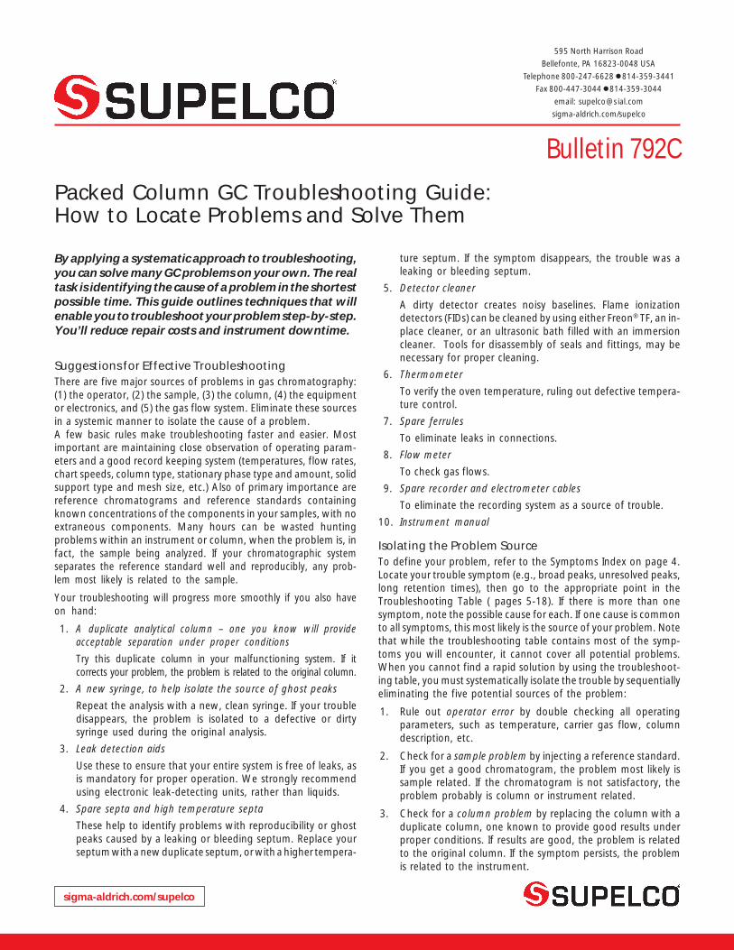
If your chromatograph is equipped with dual detector chan-nels, you have a simple but effective alternate means ofidentifying the problem source. If the symptom occurs inchannel A, disconnect at the detectors the cables which con-nect channels A and B detector outputs to channels A and Belectrometer inputs (Figure A). Reconnect the cable fromelectrometer B input to detector A output. This applies thesignal from the channel A detector output to the channel Belectrometer input and recorder. If the symptom does notappear on recorder channel B after this cable change, either thechannel A electrometer, recorder, or cable(s) is defective. If thesymptom is not eliminated, the channel A detector is theproblem source.
5. To check the carrier gas system for possible problems, refer tothe following section, Checking the Carrier Gas System.
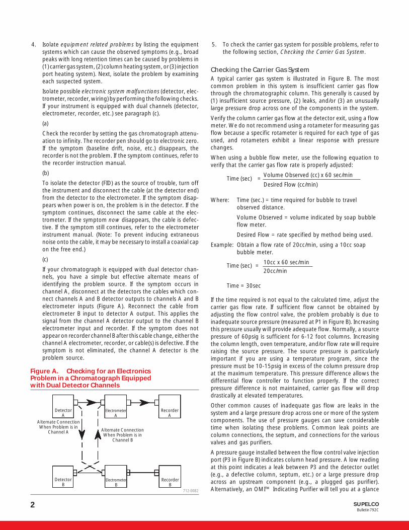
Checking the Carrier Gas SystemA typical carrier gas system is illustrated in Figure B. The mostcommon problem in this system is insufficient carrier gas flowthrough the chromatographic column. This generally is caused by(1) insufficient source pressure, (2) leaks, and/or (3) an unusuallylarge pressure drop across one of the components in the system.
Verify the column carrier gas flow at the detector exit, using a flowmeter. We do not recommend using a rotameter for measuring gasflow because a specific rotameter is required for each type of gasused, and rotameters exhibit a linear response with pressurechanges.
When using a bubble flow meter, use the following equation toverify that the carrier gas flow rate is properly adjusted:
Volume Observed (cc) x 60 sec/minTime (sec) =
Desired Flow (cc/min)
Where: Time (sec.) = time required for bubble to travelobserved distance.
Volume Observed = volume indicated by soap bubbleflow meter.
Desired Flow = rate specified by method being used.
Example: Obtain a flow rate of 20cc/min, using a 10cc soapbubble meter.
10cc x 60 sec/minTime (sec) =20cc/min
Time = 30sec
If the time required is not equal to the calculated time, adjust thecarrier gas flow rate. If sufficient flow cannot be obtained byadjusting the flow control valve, the problem probably is due toinadequate source pressure (measured at P1 in Figure B). Increasingthis pressure usually will provide adequate flow. Normally, a sourcepressure of 60psig is sufficient for 6-12 foot columns. Increasingthe column length, oven temperature, and/or flow rate will requireraising the source pressure. The source pressure is particularlyimportant if you are using a temperature program, since thepressure must be 10-15psig in excess of the column pressure dropat the maximum temperature. This pressure difference allows thedifferential flow controller to function properly. If the correctpressure difference is not maintained, carrier gas flow will dropdrastically at elevated temperatures.
Other common causes of inadequate gas flow are leaks in thesystem and a large pressure drop across one or more of the systemcomponents. The use of pressure gauges can save considerabletime when isolating these problems. Common leak points arecolumn connections, the septum, and connections for the variousvalves and gas purifiers.
A pressure gauge installed between the flow control valve injectionport (P3 in Figure B) indicates column head pressure. A low readingat this point indicates a leak between P3 and the detector outlet(e.g., a defective column, septum, etc.) or a large pressure dropacross an upstream component (e.g., a plugged gas purifier).Alternatively, an OMI™ Indicating Purifier will tell you at a glance
Figure A. Checking for an ElectronicsProblem in a Chromatograph Equippedwith Dual Detector Channels
712-0082
DetectorA
ElectrometerA
RecorderA
DetectorB
RecorderB
Alternate ConnectionWhen Problem is in
Channel A Alternate ConnectionWhen Problem is in
Channel B
ElectrometerB
3SUPELCOBulletin 792C
whether leaks are present (see products pages). A high pressurereading at P3 indicates an over-tightened septum, dirty detector,too-tightly packed column, etc. Low pressure readings on a pressuregauge at P2 will reveal an exhausted High Capacity Gas Purifier(larger than normal pressure drop). Routine observation of thispressure will enable you to determine when the gas purifier shouldbe changed.
NOTE: Many chromatographs have an intentional crimp in the carriergas line between the flow controller and the injection port, or employcapillary tubing with a small internal diameter. Consequently, thepressure reading at point P3 will be different from the column headpressure reading taken through the septum. These restrictions alsocan make it difficult to obtain sufficient carrier gas flow, particularlywhen converting an instrument for use with capillary columns.
Testing for LeaksThe most common method of leak testing is to apply a liquid (e.g.,Snoop® or HT-Leak Detector) and watch for bubbles to appear.These liquids can be aspirated into the GC system, however, and cancause unstable baselines and ghost peaks in subsequent chromato-grams. To eliminate the risk of contamination, use a thermalconductivity leak detector, such as a GOW-MAC unit. These unitsare extremely sensitive to helium or hydrogen leaks, and are equalto liquids in sensitivity for nitrogen and other heavy gases.
A simple technique for detecting septum leaks, while avoidingcontamination, is to use a Supelco™ Leak Tester – a plastic tube withconical ends. When one end is dipped in Snoop, capillary actionpulls a small amount of the liquid into the tube. If a leak is present,bubbles appear at this end when the opposite end is pressedagainst the septum nut. Because the liquid does not contact theinstrument, there is no risk of contamination.
Problems Related to Column and Septum Removaland InstallationImproperly installed columns and septa are a frequent source ofleaks, and are the most common cause of glass column breakage.An incorrectly tightened septum nut presents problems such asexcessive septum bleed, premature septum leaks, and low carriergas flow rates. We offer two torque wrenches to help ensure correctinstallation of columns and septa. The Glasrench™, used forinstalling columns, is available in two torque settings to provide thecorrect torque for the various types of ferrules. The Supelco septumnut torque wrench ensures that the correct torque is consistentlyapplied when installing septum nuts. These tools save time andmoney by eliminating over-tightening, minimizing leaks and col-umn breakage.
When changing columns or septa, it is important that you first turnoff the chromatograph oven and allow the column to cool for 10-15 minutes, then turn off the carrier gas. This procedure protectsyour column in two ways: allowing the column to cool beforeturning off the carrier gas prevents oxidation of the column packing,which can occur when a hot column is exposed to oxygen in the air.Allowing the column pressure to drop to ambient pressure preventsthe packing from blowing out of the column ends. A sudden changein pressure, when a column or a septum is removed with the carriergas flowing, can blow packing from the column.
NOTE: When storing columns, cap the ends with metal Swagelok®
caps to prevent diffusion of air into the column (and subsequentoxidation). Plastic caps do not prevent diffusion of air into a column.
Sample InjectionImproper sample injection can cause many problems in gas chro-matography. To ensure that your injections are accurate and repro-ducible, we recommend the following general guidelines andprocedures:
A. Syringe Size: Always use a syringe large enough that the desiredsample volume does not fill it to capacity, and small enoughthat the sample volume is not less than approximately 10% ofits capacity.
B. Injection Technique: Sample injection should be smooth andrapid, with quick removal of the syringe after injection, in orderto avoid peak broadening.
C. Sample Size Reproducibility: Many problems in chromatogra-phy result from difficulties in reproducing the size of a sample.Some techniques which will help ensure reproducible samplesare:
1) Automatic Injectors: These devices improve sample repro-ducibility by virtue of consistent mechanical operation. Eachstep (sampling, sample injection, syringe cleaning) is repeatedprecisely.
2) Sampling Valve Injection: Sample size is determined solelyby sample loop size, and injection is rapid and precise.Reproducibility is improved because chances for variability aregreatly reduced.
3) Solvent Flush Technique: This technique (Figure C) re-duces the problem of irreproducible injection volumes whenmaking syringe injections by hand.
a) Eliminate sample hang-up in the needle by first cleaningthe syringe, then drawing in a small aliquot of solvent.
b) Remove the syringe from the solvent and draw in a smallamount of air.
Figure B. Typical Carrier Gas System
G001131*NOTE: Our High Capacity Gas Purifier combines the functions of a moisture trap
and an oxygen trap (see products pages).
Carrier GasSource
P1
MoistureTrap
OxygenTrap
P2
ParticleTrap
TypicalLocation
FlowControlValve
P3
IdealLocation
OMI IndicatingPurifier
Septum
Injection Port
Column
Detector

SUPELCOBulletin 792C
4
c) Draw in the desired amount of sample.
d) Remove the syringe from the sample and draw in a littlemore air.
e) Verify the amount of sample in the syringe barrel. Thisis only possible with syringes that do not have plungersin the needle.
f) Quickly and smoothly inject sample into thechromatograph.
4) Syringes with Needle Plungers: Improve sample reproducibil-ity by using a syringe with a plunger in the needle. Thiseliminates sample retention in the needle dead volume. Thesolvent flush technique, above, may be useful, since a smallamount of sample hang-up can still occur.
Publication 395082Leak-resisting, low bleed septa improve baseline stability andreduce the occurrence of leak-associated problems. This publica-tion describes tests that show Thermogreen LB-2 septa exhibit lowbleed at inlet temperatures up to 350°C.
Gas Chromatography Troubleshooting TableAbbreviationsECD – electron capture detector
FID – flame ionization detector
FPD – flame photometric detector
NPD – nitrogen phosphorous detector
TCD – thermal conductivity detector
Symptoms IndexSymptom Symptom No.
Baselinechanging 23cycling 9dip 25,26drift 7drop 24noise 8off scale (zeroing problem) 6rise 22spikes, irregular 11spikes, regular 10
Carrier Gaslow flow rate 32
Column Lifeshort 33
Column Packingcompacted 31gaps in 30
Detector Responselow 3,4
Peak Shapes Incorrectcigar top 20clipped 21round top 19skewed (leading edge) 16split 17square top 18tailing 15
Peaksbroad (solvent) 27missing (all) 1missing (some) 2negative 12random extra peaks 14sample memory peaks 13unresolved 29
Quantificationirreproducible 5
Retention Timeprolonged or shortened 28
Figure C. Solvent Flush Technique
G001132,1 133
D. Proper Vapor Expansion Volume: The expansion volume of theliquid sample injected varies with the solvent and the speed ofthe injection. Too large a sample or too quick an injection willallow vaporized sample to flash backwards into the injectorport pneumatics and can cause irreproducible results. Col-umns with 2mm ID should have 2.5 cm to 10 cm of unpackedspace at the column inlet or a suitable size injection port linerplaced ahead of the column.
Other Useful PublicationsIn addition to the information presented in this guide, helpful tipsto save time and money in chromatography are offered in thefollowing FREE Supelco technical literature:
Bulletin 741The ideal ferrule provides a leak-tight seal, accommodates columnOD variations, seals with minimum torque, and does not stick to thecolumn or fitting. This bulletin offers valuable information aboutchoosing the best ferrule for various applications.
Bulletin 783Provides instructions for cleaning dirty flame ionization detectors(FIDs) and offers hints to help prevent contamination.
Bulletin 898Provides valuable information about installing and troubleshoot-ing gas delivery systems for single GC or multiple GC systems.
Bulletin 918The best gas purifier system includes multiple purifiers that helpprotect each other while protecting columns and detectors. Thisbulletin includes information needed to select suitable purifiers forcarrier gas, and for air and hydrogen used as fuel gases.
Plunger
SolventSample
Plunger
Solvent
Air
Air Air
5SUPELCOBulletin 792C
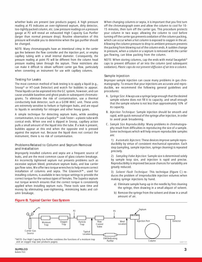
Troubleshooting TableSymptom Possible Cause Remedy
1. Check detector, electrometer settings,and fuses.
2. Reinject sample in proper column.
3. Use mirror over exhaust to check FID. Iflit, water condenses on mirror. If not lit,light flame. Check hydrogen and airflows.
4. Measure flow at detector or columnexit. If no flow, check for leaks orobstructions at column connection andseptum.
5. Replace syringe.6. Replace septum. Check column
connections.7. Increase injection port temperature (but
not in excess of liquid phase temperaturelimit) or inject sample directly ontocolumn packing.
8. Check recorder connections.Check recorder zero.Troubleshoot recorder according toinstruction manual.
9. Check collector voltage and connectionsper instrument manual.
10. Check collector spring clip connection.
1. Detector or electrometer power off /fuse blown.
2. Sample injected in wrong column(multiple-column chromatograph).
3. FID not lit.
4. No carrier gas flow.
5. Defective syringe.6. Column or septum leak.
7. Injection port temperature too low –sample not vaporized.
8. Defective recorder.
9. Defective detector, electrometer, orcable.
10. Bad connection between FID collectorand voltage source.
Normal
Problem
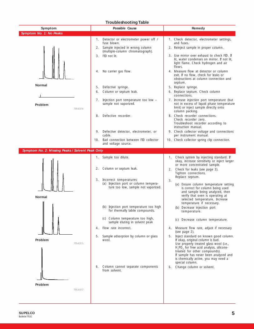
1. Check system by injecting standard. Ifokay, increase sensitivity or inject largeror more concentrated sample.
2. Check for leaks (see page 3).Tighten connections.Replace septum.
3.(a) Ensure column temperature setting
is correct for column being usedand sample being analyzed, thenverify that oven is operating atselected temperature. Increasetemperature if necessary.
(b) Decrease injection porttemperature.
(c) Decrease column temperature.
4. Measure flow rate, adjust if necessary(see page 2).
5. Inject standard on known good column.If okay, original column is bad.Use properly treated glass wool (i.e.,H
3PO
4 for free acid analysis, silicone-
treated for other compounds).If sample has never been analyzed andis chemically active, you may need aspecial column.
6. Change column or solvent.
1. Sample too dilute.
2. Column or septum leak.
3. Incorrect temperatures:(a) Injection port or column tempera-
ture too low, sample not vaporized.
(b) Injection port temperature too highfor thermally labile compounds.
(c) Column temperature too high,sample eluting in solvent peak
4. Flow rate incorrect.
5. Sample adsorption by column or glasswool.
6. Column cannot separate componentsfrom solvent.
Problem
Problem
Normal
Symptom No. 2: Missing Peaks / Solvent Peak Only
Symptom No. 1: No Peaks
795-0314
795-0315
795-0317
SUPELCOBulletin 792C
6
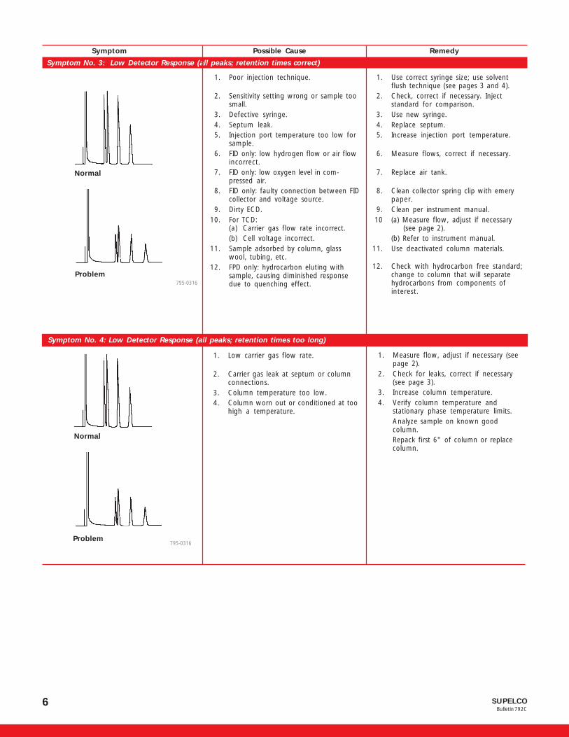
1. Use correct syringe size; use solventflush technique (see pages 3 and 4).
2. Check, correct if necessary. Injectstandard for comparison.
3. Use new syringe.4. Replace septum.5. Increase injection port temperature.
6. Measure flows, correct if necessary.
7. Replace air tank.
8. Clean collector spring clip with emerypaper.
9. Clean per instrument manual.10 (a) Measure flow, adjust if necessary
(see page 2).(b) Refer to instrument manual.
11. Use deactivated column materials.
12. Check with hydrocarbon free standard;change to column that will separatehydrocarbons from components ofinterest.
Symptom Possible Cause Remedy
Normal
Problem
1. Poor injection technique.
2. Sensitivity setting wrong or sample toosmall.
3. Defective syringe.4. Septum leak.5. Injection port temperature too low for
sample.6. FID only: low hydrogen flow or air flow
incorrect.7. FID only: low oxygen level in com-
pressed air.8. FID only: faulty connection between FID
collector and voltage source.9. Dirty ECD.
10. For TCD:(a) Carrier gas flow rate incorrect.(b) Cell voltage incorrect.
11. Sample adsorbed by column, glasswool, tubing, etc.
12. FPD only: hydrocarbon eluting withsample, causing diminished responsedue to quenching effect.
Symptom No. 3: Low Detector Response (all peaks; retention times correct)
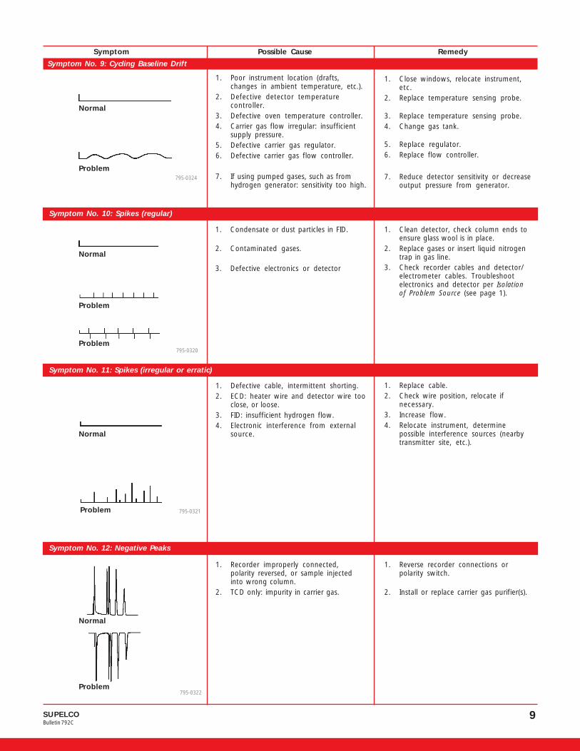
Symptom No. 4: Low Detector Response (all peaks; retention times too long)
1. Low carrier gas flow rate.
2. Carrier gas leak at septum or columnconnections.
3. Column temperature too low.4. Column worn out or conditioned at too
high a temperature.
Problem
1. Measure flow, adjust if necessary (seepage 2).
2. Check for leaks, correct if necessary(see page 3).
3. Increase column temperature.4. Verify column temperature and
stationary phase temperature limits.Analyze sample on known goodcolumn.Repack first 6" of column or replacecolumn.
795-0316
Normal
795-0316

7SUPELCOBulletin 792C
a. Retention times correct. Componentswith longest retention times show lowvalues when using normalizationtechniques.
b. Retention times correct. Differentcomponents not yielding similar peakareas for same amount.
c. Quantification varies for one compo-nent eluting over wide time span, evenusing internal standard technique.
d. Inconsistent quantification for samesample on successive analyses.
e. Low values for minor compounds.
f. Increased peak response with succes-sive injections.
1. Wrong sample.a1. Incomplete sample injection.
a2. Injection port or column tempera-ture too low or too high.
a3. Incorrect slope sensitivity withelectronic integrator.
b1. Differing detector response fordifferent components.
b2. Adsorption of components bypacking, glass wool, tubing, ortransfer lines
c1. Internal standard not compensatingfor all components in sample.
c2. Slope sensitivity of integration nothigh enough for late eluters.
d. Insufficient resolution of peaks, orpeak tailing.
e. Sample too small for accuratecounting by integrator.
f. Adsorption of components andsaturation of active sites withsample (priming the column).
1. Verify using known standard.a1. Use solvent flush technique (see
pages 3 and 4).a2. Adjust temperature
a3. Adjust slope sensitivity.
b1. Determine correction factors and/or use internal standards tech-nique.
b2. Use deactivated system.
c1. Use multiple internal standards.
c2. Use multiple internal standards.
d. Modify operating parameters orreplace column to improveresolution and eliminate tailing.
e. Increase sample size or electrom-eter range setting.
f. Use deactivated system.
Symptom Possible Cause Remedy
Symptom No. 5: Quantification Not Reproducible
Symptom No. 6: Baseline Off Scale, Cannot Zero
1. Column not conditioned properly, orcontaminated, or temperature too high.
2. Recorder problem.
3. Septum leak.
4. Wrong gas (e.g., argon/methane withFID).
5. Contamination.
6. Too much/too little gas flow.
7. TCD: imbalance in column flow.8. Contaminated detector (e.g., NPD
contaminated with Snoop, ECDcontaminated with chlorinated solvents).
9. Electrometer or detector problem.
1. Reduce column temperature toambient. If baseline normal, checksystem with good column. If okay,recondition original column.
2. Set attenuation to infinity. If recorderdoes not go to electrical zero,troubleshoot recorder per manual.
3. Check for leaks, correct if necessary(see page 3).
4. Verify gases are correct for instrumentand detector as specified in manual.
5. Turn off injection port heat. If zeroingcapability returns, clean injection portliners, etc.
6. Check flow, adjust to within manualspecifications.
7. Check flow, adjust as necessary.8. Avoid sources of contamination.
9. Troubleshoot per instrument manual.
Normal
Problem
Symptom No. 6: Baseline OffScale, Cannot Zero
795-0318
100
100
0
0

SUPELCOBulletin 792C
8
Symptom No. 8: Irregular or Unstable Baseline (baseline nosie)
1. Column bleed or contamination.
2. Contaminated detector or injectionport.
3. Carrier gas leak.
4. Poor carrier gas regulation.
5. Gas impurities/contaminated gas line.
6. Gas flows not within minimum/maximum limits (including hydrogen andair for FID) or poorly regulated flow.
7. Defective electrometer, detector, orcable.
8. FID only: collector incorrectly aligned.
9. ECD only: heater wire too close todetector wire, causing AC noise.
1. Replace column with known goodcolumn; if results okay, reconditionoriginal column.
2. Clean detector and/or injection port.
3. Check for leaks, correct as necessary(see page 3).
4. Check gas supply for sufficientpressure. Replace tank if near empty.
5. Change gas tank, clean metal tubing,use gas purifier(s).
6. Measure flows and verify againstmanual specifications.
7. Troubleshoot per Isolation of ProblemSource (see page 1).
8. Realign as required.
9. Reposition heater wire.
Normal
Problem
1. Carrier gas flow changing withtemperature during emperatureprogramming.
2. Septum or column leak.
3. Septum bleed or septum fragments incolumn.
4. Column bleed or contamination.
5. Gas flows not within minimum/maximum limits (including hydrogen andair for FID) or poorly related flow.
6. Insufficient instrument warm-up time ortemperature equilibration time.
7. Defective electrometer or detector.
8. Contaminated detector or injectionport.
1. Increase source pressure to 15psigabove column head pressure.
2. Check, correct as necessary (seepage 3).
3. Replace septum with higher tempera-ture type; repack column inlet.
4. Replace column with known goodcolumn. If results okay, reconditionoriginal column.
5. Measure flows and verify againstmanual specifications.
6. Allow time for instrument to equilibratewhen changing operating temperatureor installing another column.
7. Troubleshoot per Isolation of ProblemSource (see page 1).
8. Clean as recommended in instrumentmanual.
Normal
Problem
Symptom Possible Cause Remedy
Symptom No. 7: Baseline Drift
795-0319
795-0323
9SUPELCOBulletin 792C
Symptom Possible Cause Remedy
Symptom No. 9: Cycling Baseline Drift
1. Poor instrument location (drafts,changes in ambient temperature, etc.).
2. Defective detector temperaturecontroller.
3. Defective oven temperature controller.4. Carrier gas flow irregular: insufficient
supply pressure.5. Defective carrier gas regulator.6. Defective carrier gas flow controller.
7. If using pumped gases, such as fromhydrogen generator: sensitivity too high.
1. Close windows, relocate instrument,etc.
2. Replace temperature sensing probe.
3. Replace temperature sensing probe.4. Change gas tank.
5. Replace regulator.6. Replace flow controller.
7. Reduce detector sensitivity or decreaseoutput pressure from generator.
Normal
Problem
Symptom No. 10: Spikes (regular)
1. Condensate or dust particles in FID.
2. Contaminated gases.
3. Defective electronics or detector
1. Clean detector, check column ends toensure glass wool is in place.
2. Replace gases or insert liquid nitrogentrap in gas line.
3. Check recorder cables and detector/electrometer cables. Troubleshootelectronics and detector per Isolationof Problem Source (see page 1).
Problem
Problem
Symptom No. 11: Spikes (irregular or erratic)
1. Defective cable, intermittent shorting.2. ECD: heater wire and detector wire too
close, or loose.3. FID: insufficient hydrogen flow.4. Electronic interference from external
source.
1. Replace cable.2. Check wire position, relocate if
necessary.3. Increase flow.4. Relocate instrument, determine
possible interference sources (nearbytransmitter site, etc.).
Problem
Symptom No. 12: Negative Peaks
1. Recorder improperly connected,polarity reversed, or sample injectedinto wrong column.
2. TCD only: impurity in carrier gas.
1. Reverse recorder connections orpolarity switch.
2. Install or replace carrier gas purifier(s).
Normal
Problem
795-0324
795-0320
795-0322
Normal
795-0321
Normal

SUPELCOBulletin 792C
10
Problem(solvent injected after sample)
Normal(solvent injected after sample)
Symptom Possible Cause RemedySymptom No. 13: Extra Peaks (peaks similar to previous sample appear when solvent alone is injected)
Symptom No. 14: Extra Peaks (unlike peaks in previous sample)
1. Septum bleed, particularly in tempera-ture program.
2. Peaks from previous runs, particularly ifvery broad with short retention time.
3. Impurities from sample, solvent, samplecontainer (e.g., plasticizer from capliners or contaminated glassware),labware, or reagents used in samplepreparation, particularly when excessreagents are concentrated in work-up.
4. Condensed carrier gas impurities elutingduring temperature programming.
5. Trace impurities in lab atmosphere.
6. Air peaks or water peaks.
7. Multiple or incomplete derivativesformed in sample work-up.
8. Sample decomposition.
1. Turn off injector heater. If extra peaksdisappear, operate at lower injectortemperature or use high temperaturesepta.
2. Let analysis run longer, then repeat.
3. Run solvent blank with clean syringe. Ifextra peaks appear, change solvent; ifno extra peaks appear, run solventblank through entire sample work-up. Ifno extra peaks appear, impurities arefrom sample. If extra peaks appear,repeat analysis of solvent blank foreach step of work-up to isolate source.
4. Install or replace carrier gas purifier(s).
5. Analyze lab environment, takecorrective action as necessary.
6. Normal with TCD, using syringe injectionor aqueous samples.
7. Re-evaluate derivatization procedure.
8. Reduce temperature and/or usedifferent column.
Normal
Problem
Problem
795-0336
1. Dirty syringe.
2. Column adsorbing, then desorbingsample (particularly in temperatureprogram).
3. Adsorption in transfer line.
1. Try new syringe and clean solvent. Ifextra peaks disappear, clean syringesmore thoroughly.
2. Use more inert column materials(tubing, packing, glass wool).
3. Use glass-lined stainless steel fortransfer lines.
Previous Sample

11SUPELCOBulletin 792C
Symptom Possible Cause Remedy
Symptom No. 15: Tailing Peaks
1. Column or injection port temperaturetoo low.
2. Column deteriorating.
3. Active sample adsorbing on injectionport, transfer lines, column, or glasswool.
4. Two compounds co-eluting.
5. Needle hitting packing in column inlet(breaks particles and creates activesites).
1. Increase temperature (do not exceedmaximum temperature for column).
2. If retention times have not changedfrom when column was new, replacingfirst 6" of packing or replacing pre-column may help. If retention timeshave changed, replace column.
3. Use more inert system: all glass,Teflon®, specially designed packing, on-column injection, proper glass wooltype, etc.
4. Increase sensitivity, reduce sample size,reduce temperature approximately20°C, look for partial separation.
5. Remove several cm of packing frominlet.
Normal
Problem
Symptom No. 16: Leading Peaks
1. Column overload.
2. Two components co-eluting.
3. Sample condensation.
4. Sample decomposition.
1. Decrease sample size or select anothercolumn with higher stationary phaseloading. Alternatively, select a differentstationary phase with greater solubilityfor the component exhibiting thisbehavior.
2. Increase sensitivity, reduce sample size,reduce temperature approximately20°C, look for partial separation.
3. Check injection port and columntemperatures, increase if necessary.
4. Use inert system and deactivatedpacking.Normal
Problem 795-0340
795-0339

SUPELCOBulletin 792C
12
Symptom Possible Cause RemedySymptom No. 17: Split Peaks
Normal
Problem
1. Gross detector overload.2. Sample flashing prior to injection –
simulates two injections.
1. Reduce sample size.2. Use solvent flush technique, so sample is
contained in barrel, not in needle (seepages 3 and 4).Use less volatile solvent.
Symptom No. 18: Squared (Flat-Topped) Peaks
Normal
Problem
1. Electrometer saturated (normal forsolvent).
2. Recorder defective.
1. Reduce sample size.
2. Troubleshoot per instruction manual.
Symptom No. 19: Round-Topped Peaks
Normal
Problem
1. FID: detector overload.2. Recorder gain too low.
1. Decrease sample size.2. Adjust control.
795-0341
795-0343
795-0342

13SUPELCOBulletin 792C
Symptom Possible Cause RemedySymptom No. 20: Cigar-Top Peaks
Normal
Problem
ECD: detector overload. Reduce sample size.
Symptom No. 21: Clipped Peaks – Column Efficiency Exceptionally High
Normal
Problem
Recorder or instrument zero below minimummoveable range of recorder pen.
Shunt recorder leads and set recorderbaseline adjustment zero to approximately5% of full scale.
Symptom No. 22: Baseline Rise Before or After Peak
Normal
ProblemProblem
Sample decomposition. Use inert column and packing.
795-0344
795-0345
795-0346

SUPELCOBulletin 792C
14
Symptom Possible Cause Remedy
Symptom No. 23: Baseline Change After Large Peak
Normal
Problem
Problem
1. Contamination – water or largecomponent stripping contaminants fromcolumn.
2. Column not conditioned properly – liquidphase being stripped.
3. Pressure imbalance when gas samplingvalve activated.
1. Repack first 6" of column or replacepre-column.
2. Recondition column.
3. Correct pressure imbalance.
Symptom No. 24: Baseline Drop After Peak (FID only – flame extinguished)
1. Sample too large.2. Incorrect gas flows.
3. Flame tip plugged.4. Collector and flame tip not located
properly (whistling or humming noiseoften heard).
1. Decrease sample size.2. Check and adjust carrier gas, hydrogen,
and air.3. Clean or replace flame tip.4. Adjust collector position.
795-0347
795-0348
Normal
Problem

15SUPELCOBulletin 792C
Symptom Possible Cause Remedy
Symptom No. 25: Negative Dips After Peaks
1. Only after large peak such as solvent:sample too large.
2. After all peaks with ECD: dirty detectorcell.
1. Decrease sample size.
2. Clean detector.
Symptom No. 26: Negative Dip Before Peak
Pressure imbalance when gas sampling valveactivated.
Correct pressure imbalance.
Symptom No. 27: Broad Solvent Peaks
1. Dead volume in injection port due topoor column installation.
2. Normal with very dilute sample, as intrace analysis.
3. Poor injection technique.
4. Injection port temperature too low.5. Sample solvent interacts with detector.6. Sample solvent retained by column
(e.g., methanol by active column).
1. Use on-column injection. Ensure propercolumn connections, particularly whenchanging from one column diameter toanother.
2. —
3. Make smooth, rapid injections (seepage 3).
4. Increase injection port temperature.5. Change sample solvent.6. Change sample solvent.
Normal
Problem
Normal
Problem795-0349
G0001158
Normal
Problem
795-0350
SUPELCOBulletin 792C
16
Symptom Possible Cause Remedy
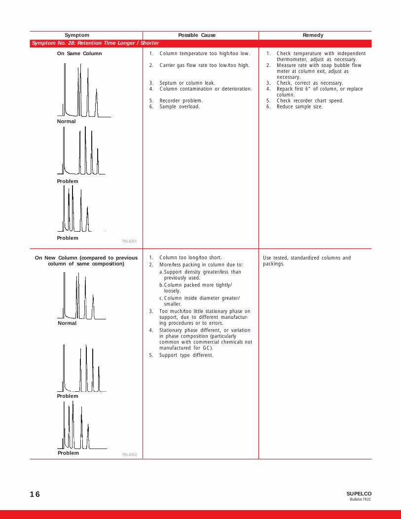
Symptom No. 28: Retention Time Longer / Shorter
On Same Column 1. Column temperature too high/too low.
2. Carrier gas flow rate too low/too high.
3. Septum or column leak.4. Column contamination or deterioration.
5. Recorder problem.6. Sample overload.
1. Check temperature with independentthermometer, adjust as necessary.
2. Measure rate with soap bubble flowmeter at column exit, adjust asnecessary.
3. Check, correct as necessary.4. Repack first 6" of column, or replace
column.5. Check recorder chart speed.6. Reduce sample size.
Normal
On New Column (compared to previouscolumn of same composition)
Normal
1. Column too long/too short.2. More/less packing in column due to:
a.Support density greater/less thanpreviously used.
b.Column packed more tightly/loosely.
c.Column inside diameter greater/smaller.
3. Too much/too little stationary phase onsupport, due to different manufactur-ing procedures or to errors.
4. Stationary phase different, or variationin phase composition (particularlycommon with commercial chemicals notmanufactured for GC).
5. Support type different.
Use tested, standardized columns andpackings.
795-0351
795-0352
Problem
Problem
Problem
Problem

17SUPELCOBulletin 792C
Symptom Possible Cause Remedy
Symptom No. 29: Unresolved Peaks
After Previous Column of SameComposition Produced Good Results
1. Column too long/too short.2. More/less packing in column due to:
a. Support density greater/less thanpreviously used.b. Column packed more tightly/loosely.c. Column inside diameter greater/smaller.
3. Too much/too little stationary phase onsupport, due to different manufactur-ing procedures or to errors.
4. stationary phase different, or variationin phase composition (particularlycommon with commercial chemicals notmanufactured for GC).
5. Support type different.
Use tested, standardized columns andpackings.
Normal
Problem
Problem795-0355
On Column Which Previously ProducedGood Results
1. Wrong column temperature.2. Wrong carrier gas flow rate.3. Sample problem:
a. Sample too large.b. Sample concentration different fromprevious analysis – minor peak“swamped” by major peak.
4. Poor injection technique (slow).5. Column contaminated or deteriorated.
1. Check and adjust temperature.2. Check and adjust flow rate.3.
a. Reduce sample size.b. Reduce sample size.
4. Make smooth, rapid injections.5. Repack first 6'” of column, or replace
column.Normal795-0356
Problem
Problem795-0354
SUPELCOBulletin 792C
18
1. Overtightened septum.2. Insufficient carrier gas source pressure.3. Insufficient source pressure for
temperature program.
4. Plugged injection port, carrier gas line,or gas purifier(s).
5. Column over-packed or glass wool tootight.
1. Loosen septum.2. Increase pressure by 10psig.
3. Flow control must have 10-15psighigher than maximum pressure(reached at maximum temperature) tofunction properly.
4. Replace tubing or gas purifier(s) asnecessary.
5. Increase carrier gas pressure. If flow stillinsufficient, install another column.(Note: not all packings have samepressure drop.) If flow okay, originalcolumn was problem. If flow low, checkplumbing system for flow restrictions(plugged detector, plugged gas filter,etc.).
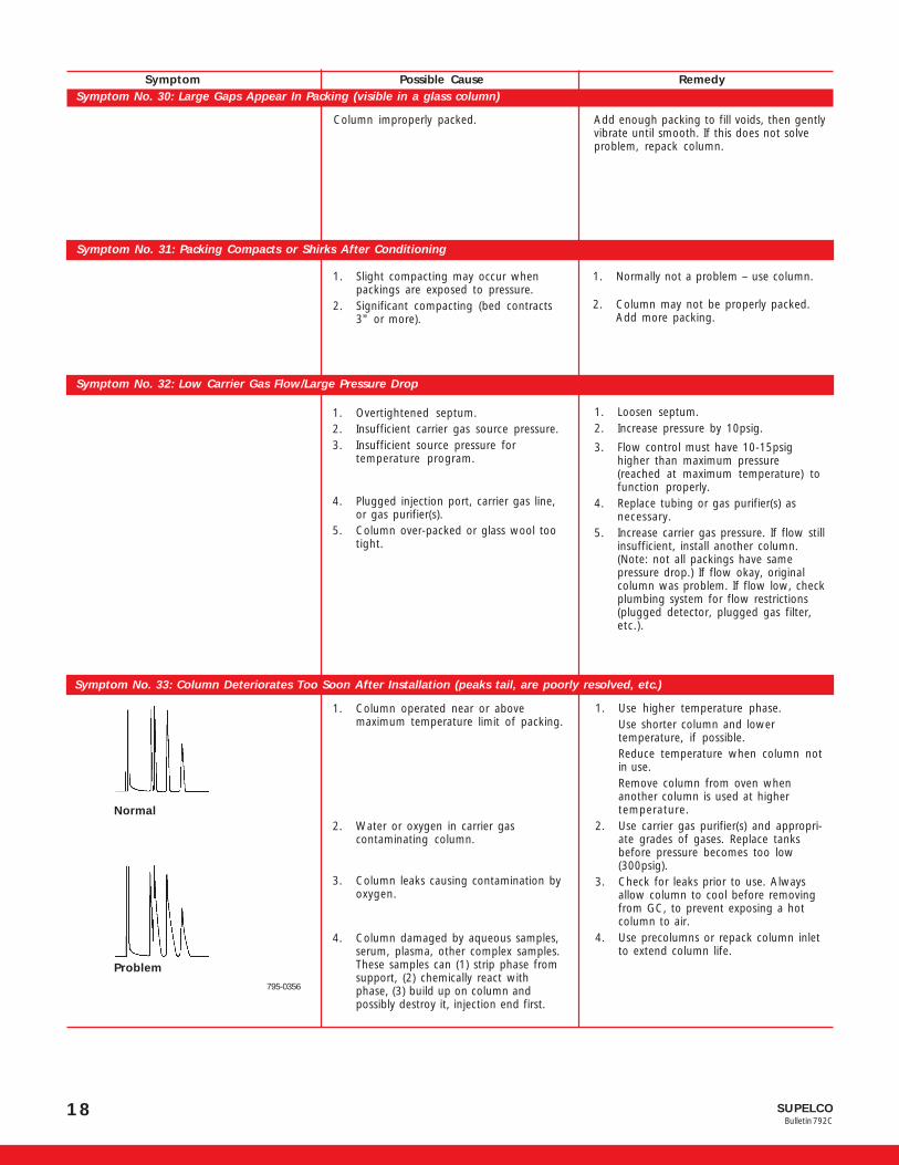
Symptom No. 33: Column Deteriorates Too Soon After Installation (peaks tail, are poorly resolved, etc.)
1. Column operated near or abovemaximum temperature limit of packing.
2. Water or oxygen in carrier gascontaminating column.
3. Column leaks causing contamination byoxygen.
4. Column damaged by aqueous samples,serum, plasma, other complex samples.These samples can (1) strip phase fromsupport, (2) chemically react withphase, (3) build up on column andpossibly destroy it, injection end first.
1. Use higher temperature phase.Use shorter column and lowertemperature, if possible.Reduce temperature when column notin use.Remove column from oven whenanother column is used at highertemperature.
2. Use carrier gas purifier(s) and appropri-ate grades of gases. Replace tanksbefore pressure becomes too low(300psig).
3. Check for leaks prior to use. Alwaysallow column to cool before removingfrom GC, to prevent exposing a hotcolumn to air.
4. Use precolumns or repack column inletto extend column life.
Normal
Problem
795-0356
Column improperly packed. Add enough packing to fill voids, then gentlyvibrate until smooth. If this does not solveproblem, repack column.
Symptom Possible Cause RemedySymptom No. 30: Large Gaps Appear In Packing (visible in a glass column)
Symptom No. 31: Packing Compacts or Shirks After Conditioning
1. Slight compacting may occur whenpackings are exposed to pressure.
2. Significant compacting (bed contracts3" or more).
1. Normally not a problem – use column.
2. Column may not be properly packed.Add more packing.
Symptom No. 32: Low Carrier Gas Flow/Large Pressure Drop

19SUPELCOBulletin 792C
Thermogreen™ LB-2 Septa● Extremely low bleed from 100°C to 350°C
● Already conditioned, ready to use
● Easier needle penetration, high puncture tolerance
Disc Diametermm Inch Qty. Cat. No.
5.0 3/16 50 206386.0 1/4 50 206519.0 11/32 50 28021-U9.5 3/8 50 206529.5 3/8 250 206669.5 3/8 1000 20677
10.0 13/32 1000 2315711.0 7/16 50 2065411.0 7/16 250 2316311.0 7/16 1000 2316411.5 11/24 50 2315412.5 1/2 50 20660-U12.5 1/2 250 2067814.0 9/16 50 20662-U16.0 5/8 50 2066317.0 21/32 50 23159
Cylindrical, for Shimadzu® instrumentsPlug Type 10 20608Plug Type 50 20633
Drilled, for Solid Phase Microextraction9.5 1 3/8 25 231619.5 1 3/8 50 23162-U
11.0 7/16 25 2316711.0 7/16 50 23168
Thermogreen LB-1 Septa● Inlet temperature: 50°C to 300°C
Disc Diametermm Inch Qty. Cat. No.
9.5 3/8 50 20659-U10.0 13/32 50 20657-U11.0 7/16 50 2065812.5 1/2 50 20661
Cylindrical, approx. 6mm diameter x 9mmThru-Hole Type 100 20667Half-Hole Type 100 20668
Pyrosep™ S-1 SeptaInlet Temperature: 300°C to 400°C. Because they are relativelyhard, Pyrosep S-1 septa must be used with a needle guide (to preventthe needle from buckling) and only at high temperatures.
Disc Diametermm Inch Qty. Cat. No.
6 1/4 10 223699.5 3/8 10 22370-U
Adapter Rings (pk. of 2)9.5mm OD x 6mm ID1 223381 Use with 6mm septa, to replace 9.5mm septa.
Septum Nuts
P00261
Description Cat. No.
Septum Nut N-1Stainless Steel1 22399
Septum Nut N-2All Aluminum 22402
1 Aluminum needle guide.
9130363
Description Cat. No.
Torque Wrench 22661
The handle of the Supelco septum nut torque wrench slips whenpreset torque (8 inch-lbs.) is reached. Helps prevent leaking septa,excess bleed, and difficult septum penetration. Deepwell socket (9/16") fits over the Supelco septum nut even with a needle guideattached.
The needle guide in Supelco septum nutsensures that the needle consistently pen-etrates the septum in the same place,prolonging septum life. The guide alsoprevents the needle from striking the edgeof the column or bending during inser-tion. The 9/16" hexagonal nut head ac-commodates our torque wrench for con-sistent, optimum tightening. Each nut issupplied with easily interchanged 1/2"and 1" guides. Use 9.5mm septa witheach nut.
The stainless steel nuts hold up under heavy use (e.g., when septaare replaced daily). We also recommend using them for reactivesamples, such as chlorinated pesticides. Aluminum nuts offereconomy in light use or when samples are nonreactive (i.e., whenmetal columns are used).
Nut N-1 fits PE-3920, 900, Sigma series, HP-5700, other portsaccepting 1/4" Swagelok nut, 7/16" threads, 20/inch.
Nut N-2 fits Varian 3700, other ports accepting 1/4" nut, 7/16"threads, 24/inch.
Use with packed columns only.
Torque Wrench

SUPELCOBulletin 792C
20
Glasrench Wrench
9130289
Our Glasrench lets you consistently apply just the correct forceneeded to tighten the ferrule – the wrench slips when too muchforce is applied. You know when to stop tightening and you don’tdamage your column. Because different ferrules require differentamounts of tightening force, we offer two color-coded models.9/16", for 1/4" fittings.
Leak Tester KitEliminates placing leak detection fluid, a potential contaminant,directly onto the septum. Dip one end of the leak tester tube intoSnoop and place the other end into the septum nut or needle guide.Bubbles indicate a leak. Kit includes 10 leak tester tubes and 8ounces of Snoop.
Leak-Tec® Leak DetectorUse at temperatures up to 210°C – Leak-Tec leak detector will notbubble on a heated part unless there is a leak. 283g pressurized can.
Select the best ferrule for your application:
Ferrule Max. Temp. Characteristics
Supeltex M-1 250°C Ideal for connections to mass spectrometers. High reusabilityceramic-filled Teflon Isothermal use only
Supeltex M-2 350°C High reusabilitydu Pont VESPEL® SP-1(100% polyimide)
Supeltex M-2A 400°C Seals at 1/4 turn past fingertight. High reusabilitydu Pont VESPEL SP-21 Won’t stick to metal or glass.(85% polyimide/15% graphite)
Supeltex M-2B 350°C Conforms easily to capillary column, ensuring an effective seal anddu Pont VESPEL SP-211 less chance of breakage.(10% Teflon graphite/75% polyimide)
Supeltex M-4 450°C Seals at 1/4 turn past fingertight. Maximum sealing surface contact,flexible graphitere reduced risk of column contamination at installation.
O-Ring 200°C Seals column having OD over or under specifications.silicone
Description Cat. No.
Leak Tester Kit 22660-USnoop, 8oz. bottle 20434Leak-Tec Leak Detector, 283g 20566
P000182
Description Cat. No.
GlasrenchModel A (for Supeltex M-1, Supeltex M-2 ferrules) 22901Model C (for Supeltex M-2A, Supeltex M-4 ferrules) 22903
Supeltex Ferrules for Packed ColumnsSupeltex Column ODFerrule Type 1/4" 6mm 1/8" 1/16"(Temp. Limit) Cat. No. Cat. No. Cat. No. Cat. No. Qty.
M-1 22086-U 22089-U 22496 22386 10(250°C) 22087-U – 22309 – 100
M-2 22320-U – 22321 20644-U 10(350°C) 22475 – 22476 – 50
M-2A 22481 22393 22483-U 22487-U 10(400°C) 22471 – 22472 – 50
Indented Blank1 – – – 22488 10
M-4 22492 22493 22491 22495-U 10(450°C) 22478 – – – 50
O-Rings(200°C) 20407 – – – 100
Ferrule ID: 1/4" 6mm 1/8" 1/16"
1Drill to fit your column.
TrademarksBransonic – Branson Cleaning Equipment Co.CapSeal Bullet, Glasrench, OMI, PureCol, Pyrosep, Supelco, Supeltex, Thermogreen
– Sigma-Aldrich Co.Freon, VESPEL – E.I. du Pont de Nemours & Co., Inc.GOW-MAC – GOW-MAC Instrument Co.Hamilton – Hamilton Co.Hewlett-Packard – Hewlett-Packard Corp.Leak-Tec – American Gas & Chemical Co., Ltd.Perkin-Elmer – Perkin-Elmer Corp.Shimadzu – Shimadzu Corp.Snoop – Nupro Co.Swagelok – Crawford Fitting Co.
Supeltex™ ferrules form leaktight seals without sticking to yourcolumn. And they don’t require back ferrules.
We highly recommend:
● Supeltex M-4 and Supeltex M-2A ferrules for glass columns
● Supeltex M-2A and Supeltex M-2 ferrules for metal columns22492

21SUPELCOBulletin 792C
713-0449
PureCol™ Column Inlet LinersWhen nonvolatiles accumulate in the column inlet, you must replace several inches of packing – or the entire column. Asilanized glass PureCol liner, inserted in the column inlet, solves this problem simply and inexpensively. When columnperformance begins to deteriorate, you can quickly and conveniently replace the insert – often without removing thecolumn from the instrument. Replacement time is comparable to replacing a septum. Replace the PureCol liner when youchange the septum, or when you analyze a new type of sample.
PureCol liners are available in two sizes. The smaller size fits 2mm ID glass columns with chamfered ends and 7cm of straight,unpacked inlet. The larger size fits any 4mm ID glass column that has 7cm of straight, unpacked inlet. Use PureCol linerswith a 2" (5cm) 21-gauge or finer needle.
G000405-412
Deactivated Glass Liners for Packed Column Injection PortsWe can prepare liners to your specifications. Just call our Ordering and Customer Service Departments for a quote.
These deactivated glass liners prevent reaction between active sample components and the injection port’s metal surfaces.
Instrument Liner Mfr.Manufacturer & Model Description Part No. Qty. Cat. No.
Hewlett-Packard® 5700, 5830/40A, 5880A, 5890A
Glass liner 5080-8732 5 2050891.5mm x 3mm OD 1.8mm ID 25 20511
Perkin-Elmer® 3920Glass liner 0009-1958 1 –2.75mm IDGlass liner (small bore) 0009-1614 1 26301
143mm x 4.6mm OD 1.5mm ID
Perkin-Elmer 8000, Sigma 2000/2100, Sigma 1B-4B & 300 manufactured 1978 or laterGlass liner 0330-2221 1 26300-U2.75mm ID 5 26409Glass liner (small bore) 0330-2243 25 –
101mm x 4.6mm OD, 1.5mm ID 1 –
Perkin-Elmer Auto System, Model 9000Unpacked
Packed column N610-1048 1 –3mm ID 5 26316,05
112mm x 6mm OD 25 26316,25Packed (deactivated glass wool)
For dirty samples 1 –3mm ID 5 26317,05
112mm x 6mm OD 25 26317,25
ShimadzuWool packed
104mm x 4.5mm OD 3mm ID 221-14755 1 –
Varian Universal Flash Injectors 1060-60, 3300, 3400, 3500-3600, older 3700/VISTAGlass injector insert 37-000813-00 1 26369(wool packed) 5 26426
72mm x 6.3mm OD 25 26481
Varian Moduline and Other Older ModelsGlass insert 6-000107-01 10 26370-U
5½”/14cm x 1/8" ID 1.8mm ID
Description Qty. Cat. No.
For 2mm ID Columns (chamfered inlet only)10 2053450 20536
For 4mm ID Columns10 20540-U50 20543
Order your glass column with a PureCol liner already in place – atno extra cost. Just specify “glass column with PureCol liner” on yourorder.

SUPELCOBulletin 792C
22
P000218
Humonics Veri-Flow 500 Electronic Flowmeter Humonics Optiflow Flowmeters
P000221
● Calibrated for nitrogen, helium, hydrogen, air, 5% argon/methane (certificate supplied)
● Range of 5-500mL/min; accurate to within ±2% of readingor 0.25mL (whichever value is larger)
● Continuous readings in volume, linear velocity, or split ratio● EPC compatible● 9-pin RS 232 communication port for recording data● Power adapter jack and recharger● Only 4 x 5 x 3" (10 x 12.5 x 7.5cm)
P000222
Humonics Model 1000 Liquid Flowmeter
●●●●● Easy set-up and operation
●●●●● NIST traceable
Humonics digital liquid flowmetersreplace the tedious and time-consum-ing glass burette and stopwatch tra-ditionally used to measure flow rates– a microcomputer and infrared op-tics are used to track a rising volumeof liquid within a tube of precision-bore glass. Absolute accuracy is es-tablished by comparing the perfor-mance of the instrument to an NIST-registered burette.
An outstanding instrument foranalysts who want a simple, con-tinuous-reading flowmeter forgeneral GC applications.
The Veri-Flow 500 Electronic Flow-meter is multiple-point calibratedto NIST-certified volumetric stan-dards, for superior accuracy and tohelp you comply with ISO 9000,GLP, and other stringent qualitycontrol protocols. Operation is pulse-free, unaffected by tempera-ture or pressure changes, and the unit is fully compatible withelectronic pressure control systems. Operates on internal recharge-able batteries. Very low power consumption and automatic shut-off.
Description Cat. No.
Veri-Flow 500 Electronic Flowmeter1
110VAC 23143with universal charger, 110-240VAC, 50/60Hz2 231421 CE approved
● Four flow ranges available;accurate to within ±2 or±3% of any reading
● Portable – includes stan-dard 9-volt battery
● Patented U-tube designfor lighter-than-air gases
● Fault condition display● Automatic power-off for
extended battery life● Low battery indicator
● Field replaceable tubes
● Compatible with electronic pressure control
● Computer interface capability on Model 650
These high-precision instruments combine the simplicity and ver-satility of a bubble meter with the speed and accuracy of a micro-processor, providing you with a reliable means of measuring gasflow.
The versatile units can be used with all gases. And they feature aneasy-to-read, accurate digital display, eliminating the need fortedious bubble watching, timing, and flow rate/time conversions.The bubble is visible for your observation.
Optiflow Digital Flowmeters help you comply with the qualityprotocols of the American Society for Quality Control, ISO 9000,and Good Laboratory Practice. Each unit is individually calibrated tothe registered standards of the National Institute of Standards andTechnology and comes with a certificate of calibration. A recalibrationservice is available.
Optiflow 420 Digital FlowmeterFlow Range: 0.5-50mL/minAccuracy: ±3% of any readingDisplay: mL/min or linear velocity
Optiflow 570 Digital FlowmeterFlow Range: 0.5-700mL/minAccuracy: ±2% of any readingDisplay: mL/min or split ratio
Optiflow 650 Digital FlowmeterFlow Range: 5-5000mL/minAccuracy: ±2% of any readingDisplay: mL/min or split ratio
Description Cat. No.
Model 1010 Liquid Flowmeter 110VAC –Model 1010 Liquid Flowmeter 220VAC –Model 1000 Liquid Flowmeter 110VAC 55090-UOptiflow 420 Digital Flow Meter 22806Replacement Flow Tube 22779-UOptiflow 520 Digital Flow Meter 22910Replacement Flow Tube 22776Optiflow 570 Digital Flow Meter 22741-UReplacement Flow Tube 22777Optiflow 650 Digital Flow Meter 22912Replacement Flow Tube 22778
Model Flow Range (mL/min) Resolution Calibration Points
1010 0.100 - 1.999 0.001 0.5, 1.5, 5mL/m in2.00 - 6.00 0.01
1000 0.100 1.999 0.001 1.5, 3, 5mL/min2.00 - 9.99 0.0110.0 - 30.0 0.1

23SUPELCOBulletin 792C
P000330
GOW-MAC® Gas Leak Detectors
Using liquids to detect gas leaks can be poor economy, especially ina capillary GC system. Even a small amount of liquid leak detector thatseeps into a fitting, or through the septum, can damage your columnor create baseline noise. GOW-MAC gas leak detectors easily andquickly pinpoint gas leaks too small to detect with soap solution.
GOW-MAC gas leak detectors operate on the same principle as athermal conductivity detector – they respond to any gas mixture thathas a thermal conductivity value different from that of air. With anintrinsically high signal-to-noise ratio, amplification provides maxi-mum usable sensitivity: helium leaks of 1.0 x 10⁻⁵ cc/sec andrefrigerant leaks of 1.0 x 10⁻⁴ cc/sec are easily detected.
Both models have a 1-year warranty from GOW-MAC.
Specifications: Deluxe DetectorOutput: Audio. Frequency changes with concentration;
adjustable threshold and speaker volume.Range: High: x1; Low: x100
Dimensions: 10 3/4 x 8 1/4 x 3 5/8" (27 x 21 x 9cm)(excluding handle)
Weight: 9lb/4.1kg (shipping wt.: 12lb/5.4kg)Power: Rechargeable lead/acid gel battery, 8V, selectable
115/230VAC, 50/60 Hz
Specifications: Miniature DetectorOutput: Visual LED bar graph alerts you to leaksRange: High: x1; Low: x100
Dimensions: 3 1/4 x 1 13/16 x 5 1/4" (8 x 4.5 x 13cm)Weight: >1lb/474g, without charger
Line Voltage: Rechargeable Ni-Cd battery, 7.2V/ 800mAmp/hr;recharger included: 115VAC/60Hz or 230VAC/50Hz
Description Cat. No.
GOW-MAC Gas Leak DetectorsDeluxe Model 21-2501 22409
Mini Detector: Model 21-050with 115VAC/60Hz recharger 22807with 230VAC/50Hz recharger2 22808Carrying Case for Mini Detector 22809
1Does not have a CE mark.2CE approved.
NOTE: These GOW-MAC gas leak detectors are not intended for determining leaksof combustible gases. They are intended for nonspecific applications, todetermine low level leaks of gases with thermal conductivity different from thatof air. We recommend a combustible gas detector for monitoring combustiblegases in possibly hazardous situations.
Bransonic® Ultrasonic CleanerUltrasonic cleaning is fast, effective, and safe, and this Bransoniccleaner has more ultrasonic power than most comparable models.Ensures faster, more thorough cleaning of dirt, protein residue, etc. fromyour glassware, fittings, syringes and needles, and other apparatus.Recessed cleaning tank is enclosed in durable, solvent and impactresistant plastic, for longer life.Tank Size:
5 1/2" x 6" x 4" deep (14 x 15 x 10cm);1/2 gallon/1.8 liter capacity
Overall Size:7 1/2" x 8 1/2" x 9" (19 x 22 x 23cm)
Weight:7 lbs. (3.2kg)
Immersion CleanerAn aqueous and nontoxic surfactant solution that removes heavydeposits of silica from a detector. Recommended for dirty detectorsnot effectively cleaned by our in-place detector cleaner (Cat. No.33000-U). Mix concentrate 1:10 with water.
In-Place Detector CleanerA halocarbon liquid that cleans the detector in place. Just injectmicroliter quantities into a packed column while it is connected toa lighted flame detector. HF, produced by combustion of thecleaner, removes silica deposits from detector electrodes. Alsouseful for removing greases and oils from glassware, syringes, etc.100mL bottle.
Jet and Needle Cleaning KitTen wires in each of five sizes (0.00350, 0.00497, 0.00659, 0.00815,and 0.01207" OD), plus a bottle of syringe cleaning solution. Perfectfor cleaning small orifices such as FID jets and syringe needles.Packaged in a reusable box that prevents wires from being damagedduring storage.
Wire Brush Detector Cleaning KitA collection of wire brushes specially tailored to clean FIDs andinjection ports that accept 1/4" columns. Brass brushes preventscratching and marring of expensive FID components and savedowntime by allowing the detector to be cleaned while hot.
Each kit includes two detector brushes, one injection port tubebrush, a brass toothbrush (for cleaning jets and other odd surfaces),and a piece of fine emery cloth to clean electrical contacts.Just measure your collector assembly ID and choose the closest kit.Instructions are included.
Description Cat. No.
Bransonic Ultrasonic Cleaner1
110VAC 22326220VAC 22336Cleaning Solution, 1 quart (0.9 liter) 22335Immersion Cleaner, 100mL 22662In-Place Detector Cleaner 33000-UJet and Needle Cleaning Kit 21578
Wire Brush Detector Cleaning KitCollector Assembly ID
0.145" (e.g., HP 5700, 5830) 224030.187" (e.g., PerkinElmer Sigma Series 3900, 900) –0.235" (e.g., Varian 3700, 1400, 2700) 22404
1 CE approved.

We are committed to the success of our Customers, Employees and Shareholders through leadership in Life Science, High Technology and Service.
The SIGMA-ALDRICH Family® ® ™
©2004 Sigma-Aldrich Co. Printed in USA. Supelco brand products are sold through Sigma-Aldrich, Inc. Sigma-Aldrich, Inc. warrants that its products conform to theinformation contained in this and other Sigma-Aldrich publications. Purchaser must determine the suitability of the product(s) for their particular use. Additional termsand conditions may apply. Please see reverse side of the invoice or packing slip. Supelco is a registered trademark of Sigma-Aldrich Co.AIS T109792C
®
Order/Customer Service 800-247-6628, 800-325-3010Fax 800-325-5052 ● E-mail [email protected]
Technical Service 800-359-3041, 814-359-3041Fax 800-359-3044, 814-359-5468 ● E-mail [email protected]
SUPELCO ●●●●● 595 North Harrison Road, Bellefonte, PA 16823-0048 ●●●●● 814-359-3441
sigma-aldrich.com/supelco
P000356
High Capacity Gas Purifier
To reliably protect your GC columns and detectors from oxygen andwater vapor damage, you should use a gas purifier specificallydesigned to ensure maximum gas purity. The Supelco High CapacityGas Purifier tube is heated inside an oven, and oxygen and waterreact with the gettering material in the tube. Chemical reaction withthe gettering material prevents these contaminants from returningto the gas stream. The High Capacity Gas Purifier also removescarbon monoxide and carbon dioxide.
A single, replaceable High Capacity Gas Purifier tube can remove 14liters of oxygen or 35 liters of water vapor (STP). It removes oxygenand water from at least 60 tanks of heavily contaminated gas — gascontaining 100ppm of oxygen and/or water. It efficiently removesoxygen and water at gas flow rates up to 1100mL/minute, and youcan use it with any common carrier gas except hydrogen.
The stainless steel converter tube is 10" x 1/2" OD. The split-sidedheater is 10" long. An integral mounting bracket allows you to boltthe unit to a bench top or wall. The 90 watt power consumptionmakes the unit as economical to operate as a light bulb.1-year guarantee; elements guaranteed for 90 days.
Description Cat. No.
High Capacity Gas Purifier110VAC, 1/8" Fittings1 23800-U110VAC, 1/4" Fittings1 23802220VAC, 1/8" Fittings1 23801220VAC, 1/4" Fittings1 23803
Replacement Purifier Tubes1/8" Fittings 223961/4" Fittings 22398
1CE approved.
Pressure Gauge KitUse to indicate when the high capacity gaspurifier tube should bereplaced. 2"/5cm gauge (0-100psi), NPT to Swagelok adapter, 18"/1/2m of 1/8" copper line, 1/8" tee, installation instructions.
Description Cat. No.
Pressure Gauge Kit 20392
OMI Indicating Purifiers
P000245
● Simultaneously remove O2, water va-por, CO, CO2, most sulfur compounds,most halogen compounds, alcohols,phenols to less than 10ppb
● Purify helium, hydrogen, nitrogen,argon-methane
● Color change indicates purifier ex-haustion
● Glass body does not diffuse air or off-gas
● Ideal for Hall, ECD, GC/MS detectionsystems
● OMI-4 purifier protects multiple instruments (three times thecapacity of OMI-2 tubes)
Install an OMI purifier downstream from your primary gas purifyingdevice, and tell at a glance whether or not oxygen and water vaporare being effectively eliminated from your system. The OMI purifierwill provide point-of-use gas polishing and final visual assuranceof gas quality before the gas enters the GC. OMI purifier tubescontain Nanochem resin, developed for the demanding gas purityneeds of the semiconductor manufacturing industry. As little as1ppm of oxygen or water will change the indicating resin from blackto brown.
Dimensions of OMI PurifiersOMI-2
Tube: 6"/15.2cm x 5/8"/1.6cm ODTube Holder: 10"/25.4cm x 1 1/2"/3.8cm OD
Endfittings: 2 1/2"/6.4cmOMI-4
Tube: 12"/30.5cm x 1"/2.5cm ODTube Holder: 16"/40.6cm x 1 1/2"/3.8cm OD
Endfittings: 2 1/2"/6.4cm
Description Cat. No.
OMI-2 Purifier Tube1 23906OMI-2 Tube Holder, 1/8" fittings1 23921Seal Kit for OMI-2 Tube Holder(includes 2 Teflon seals and tool) 23917
OMI-4 Purifier Tube1 23909OMI-4 Tube Holder, 1/8" fittings1 23926OMI-1 Replacement Tube2
(includes 2 ferrules) 23900-U3/8" Ferrules (pk. of 10) 223111/4" to 1/8" Swagelok SS Reducer 215171 First time users must order both purifier tube and corresponding holder. Holder is
reusable.2 Will not fit OMI-2 tube holder – use with OMI-1 installation kit only (kit no longer
available).
Change purifier tube whenpressure drop exceeds 10psi.