bulletin no.: date: may 2016 recall bulletinmodels: 1995-1997 cadillac deville concours, seville,...
TRANSCRIPT

Copyright 2016 General Motors. All Rights Reserved.
Recall Bulletin
Bulletin No.: Date:
04014E May 2016
PRODUCT SAFETY RECALL
SUBJECT: Engine Fuel Rail - Replace
MODELS: 1995-1997 Cadillac DeVille Concours, Seville, Eldorado 1996-1997 Cadillac DeVille Equipped with 4.6L V8 (RPO LD8 – VIN Y; RPO L37 – VIN 9) Engine 1995-1997 Oldsmobile Aurora Equipped with 4.0L V8 (RPO L47 – VIN C) Engine
Information regarding parts ordering been revised in the Part Information section. Please discard all copies of bulletin 04014D.
It is a violation of Federal law for a dealer to deliver a new motor vehicle or any new or used item of motor vehicle equipment (including a tire) covered by this notification under a sale or lease until the defect or noncompliance is remedied.
All involved vehicles that are in dealer inventory must be held and not delivered to customers, dealer traded, or used for demonstration purposes until the repair contained in this bulletin has been performed on the vehicle.
CONDITION
General Motors has decided that a defect which relates to motor vehicle safety exists in all 1995-1997 Cadillac DeVille Concours, Seville and Eldorado, 1996-1997 Cadillac DeVille; and 1995-1997 Oldsmobile Aurora model vehicles. These vehicles have a condition in which the original equipment nylon tubing used in the fuel rail construction may degrade and crack. Additionally, the 1995 Oldsmobile Aurora uses a unique underhood fuel return line that may crack at unusually high rates. Cracking of the fuel rail can result in a fuel leak into the engine compartment. The operator may experience fuel odor and possibly engine stalling due to loss of fuel pressure to the engine. If this event were to occur, and if an ignition source were present, an engine compartment fire could occur.
CORRECTION
Dealers are to inspect and, if necessary, replace the engine fuel rail with a new stainless steel fuel rail. Dealers will also replace the chassis fuel lines on 1995 Oldsmobile Aurora model vehicles.
Page 2 May 2016 Bulletin No.: 04014E
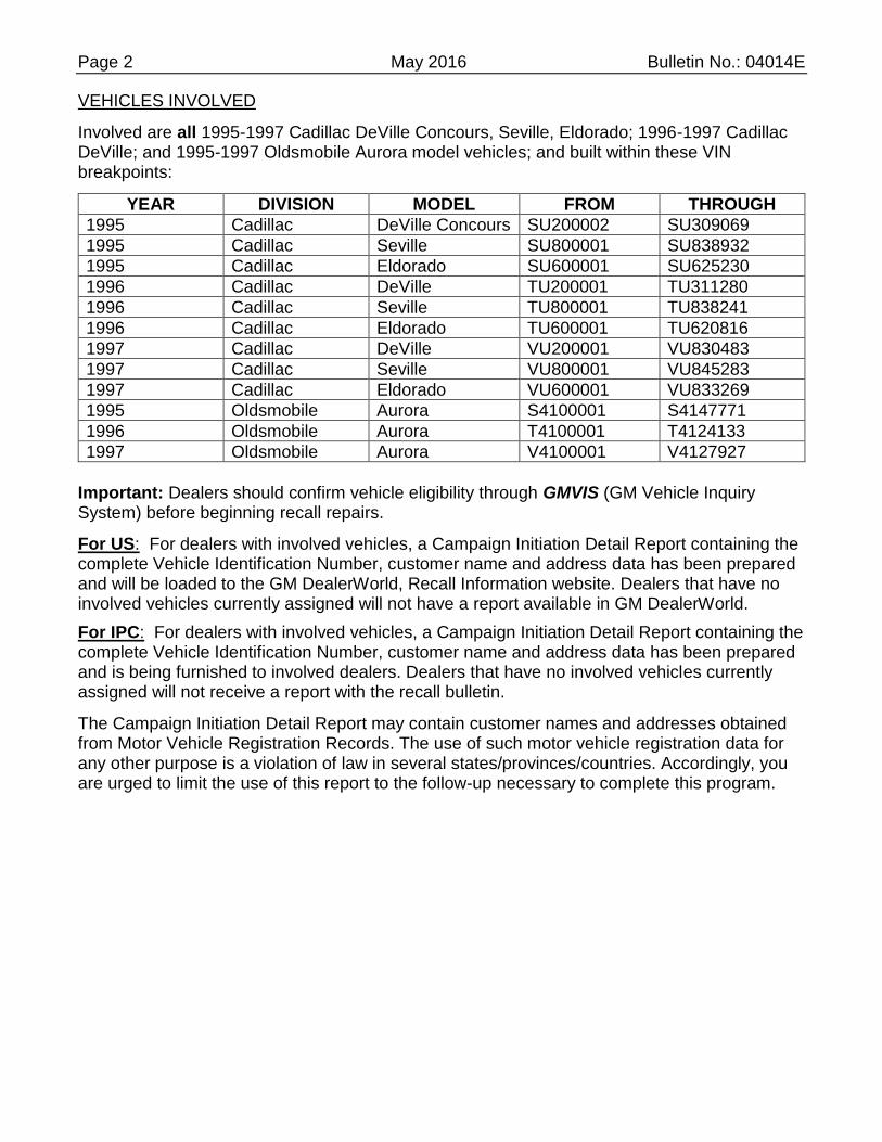
VEHICLES INVOLVED
Involved are all 1995-1997 Cadillac DeVille Concours, Seville, Eldorado; 1996-1997 Cadillac DeVille; and 1995-1997 Oldsmobile Aurora model vehicles; and built within these VIN breakpoints:
YEAR DIVISION MODEL FROM THROUGH
1995 Cadillac DeVille Concours SU200002 SU309069
1995 Cadillac Seville SU800001 SU838932
1995 Cadillac Eldorado SU600001 SU625230
1996 Cadillac DeVille TU200001 TU311280
1996 Cadillac Seville TU800001 TU838241
1996 Cadillac Eldorado TU600001 TU620816
1997 Cadillac DeVille VU200001 VU830483
1997 Cadillac Seville VU800001 VU845283
1997 Cadillac Eldorado VU600001 VU833269
1995 Oldsmobile Aurora S4100001 S4147771
1996 Oldsmobile Aurora T4100001 T4124133
1997 Oldsmobile Aurora V4100001 V4127927
Important: Dealers should confirm vehicle eligibility through GMVIS (GM Vehicle Inquiry System) before beginning recall repairs.
For US: For dealers with involved vehicles, a Campaign Initiation Detail Report containing the complete Vehicle Identification Number, customer name and address data has been prepared and will be loaded to the GM DealerWorld, Recall Information website. Dealers that have no involved vehicles currently assigned will not have a report available in GM DealerWorld.
For IPC: For dealers with involved vehicles, a Campaign Initiation Detail Report containing the complete Vehicle Identification Number, customer name and address data has been prepared and is being furnished to involved dealers. Dealers that have no involved vehicles currently assigned will not receive a report with the recall bulletin.
The Campaign Initiation Detail Report may contain customer names and addresses obtained from Motor Vehicle Registration Records. The use of such motor vehicle registration data for any other purpose is a violation of law in several states/provinces/countries. Accordingly, you are urged to limit the use of this report to the follow-up necessary to complete this program.
Page 3 May 2016 Bulletin No.: 04014E
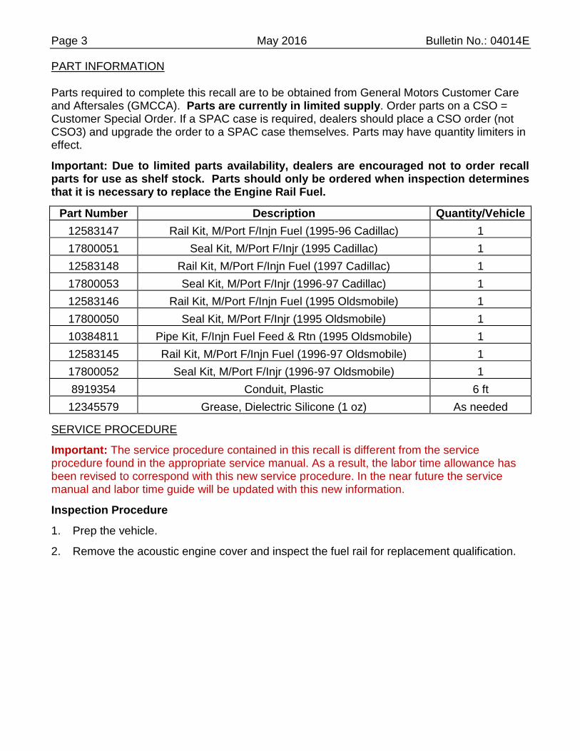
PART INFORMATION
Parts required to complete this recall are to be obtained from General Motors Customer Care and Aftersales (GMCCA). Parts are currently in limited supply. Order parts on a CSO = Customer Special Order. If a SPAC case is required, dealers should place a CSO order (not CSO3) and upgrade the order to a SPAC case themselves. Parts may have quantity limiters in effect.
Important: Due to limited parts availability, dealers are encouraged not to order recall parts for use as shelf stock. Parts should only be ordered when inspection determines that it is necessary to replace the Engine Rail Fuel.
Part Number Description Quantity/Vehicle
12583147 Rail Kit, M/Port F/Injn Fuel (1995-96 Cadillac) 1
17800051 Seal Kit, M/Port F/Injr (1995 Cadillac) 1
12583148 Rail Kit, M/Port F/Injn Fuel (1997 Cadillac) 1
17800053 Seal Kit, M/Port F/Injr (1996-97 Cadillac) 1
12583146 Rail Kit, M/Port F/Injn Fuel (1995 Oldsmobile) 1
17800050 Seal Kit, M/Port F/Injr (1995 Oldsmobile) 1
10384811 Pipe Kit, F/Injn Fuel Feed & Rtn (1995 Oldsmobile) 1
12583145 Rail Kit, M/Port F/Injn Fuel (1996-97 Oldsmobile) 1
17800052 Seal Kit, M/Port F/Injr (1996-97 Oldsmobile) 1
8919354 Conduit, Plastic 6 ft
12345579 Grease, Dielectric Silicone (1 oz) As needed
SERVICE PROCEDURE
Important: The service procedure contained in this recall is different from the service procedure found in the appropriate service manual. As a result, the labor time allowance has been revised to correspond with this new service procedure. In the near future the service manual and labor time guide will be updated with this new information.
Inspection Procedure
1. Prep the vehicle.
2. Remove the acoustic engine cover and inspect the fuel rail for replacement qualification.

Page 4 May 2016 Bulletin No.: 04014E
4375760
2.1 If the fuel rail has the words “GM213M Type F” or “M-Bond” written on the tubing with a dot ink-jet type white/yellow printing, it is a service fuel rail with the M-Bond tubing and does not need replacement. Submit a claim for inspect only and close the recall.
4375762
2.2 If the fuel rail is a stainless steel material, it is a service fuel rail and does not need replacement. Submit a claim for inspect only and close the recall.

Page 5 May 2016 Bulletin No.: 04014E
2.3 If the words “GM213M Type F” or “M-Bond” are not clearly readable on the tubing or the rail is not constructed of stainless steel, the fuel rail requires replacement. Continue with the fuel rail removal and replacement procedure.
Fuel Rail Removal and Replacement Procedure
Tools Required
J 34730-1A Fuel Pressure Gauge
J 37088-A Fuel Line Disconnect Tool Set
J 41081 Injector Remover
Notice: Do NOT remove the air cleaner assembly, intake air duct, throttle body or EGR pipe. The replacement fuel rail does not require the removal of these components due to the revised design. Removal of components not necessary for this procedure will require replacement of damaged gaskets and EGR pipe.
Fuel Rail Removal
1. Allow the engine too cool to ambient temperature.
2. Note the customer's radio settings.
3. Raise the hood.
Aurora
1461407
Page 6 May 2016 Bulletin No.: 04014E
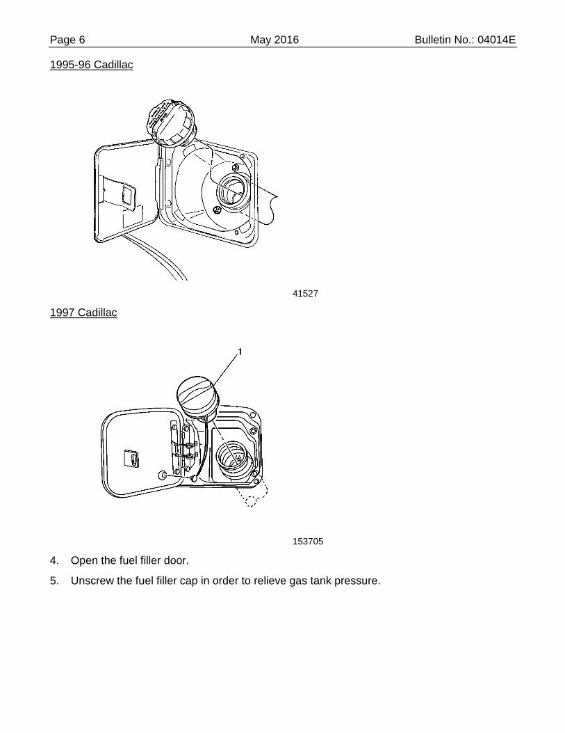
1995-96 Cadillac
41527
1997 Cadillac
153705
4. Open the fuel filler door.
5. Unscrew the fuel filler cap in order to relieve gas tank pressure.
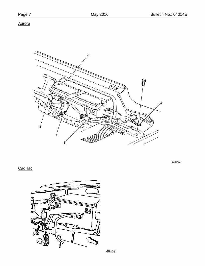
Page 7 May 2016 Bulletin No.: 04014E
Aurora
228002
Cadillac
48462

Page 8 May 2016 Bulletin No.: 04014E
Caution: Before servicing any electrical component, the ignition key must be in the OFF or LOCK position and all electrical loads must be OFF, unless instructed otherwise in these procedures. If a tool or equipment could easily come in contact with a live exposed electrical terminal, also disconnect the negative battery cable. Failure to follow these precautions may cause personal injury and/or damage to the vehicle or its components.
6. Disconnect the negative cable at the battery.
Aurora
42751
Cadillac
20426
7. Remove the 4 fuel injector sight shield nuts.
8. Remove the fuel injector sight shield.

Page 9 May 2016 Bulletin No.: 04014E
180378
Caution: Relieve the fuel system pressure before servicing fuel system components in order to reduce the risk of fire and personal injury.
After relieving the system pressure, a small amount of fuel may be released when servicing the fuel lines or connections. In order to reduce the chance of personal injury, cover the regulator and the fuel line fittings with a shop towel before disconnecting. This will catch any fuel that may leak out. Place the towel in an approved container when the disconnection is complete.
9. Relieve the fuel rail pressure at test port connection with the J 34730-1A.
9.1 Wrap a shop towel around test port connection while connecting gauge to avoid spillage.
9.2 Connect the gauge to the test port connection.
9.3 Install the bleed hose into an approved container.
9.4 Open bleed valve to bleed system pressure.
9.5 Drain any fuel remaining in the J 34730-1A into an approved container.

Page 10 May 2016 Bulletin No.: 04014E
Aurora
1461407
1995-96 Cadillac
41527

Page 11 May 2016 Bulletin No.: 04014E
1997 Cadillac
153705
10. Tighten the fuel filler cap.
11. Close the fuel filler door.
Important: Steps 12–18 MY1995-96 Cadillac ONLY.
12. Disconnect the vacuum manifold from the intake manifold adapter and reposition.
13. Disconnect the transmission vent tube from the retainer on the cruise control servo bracket.
14. Release the retainer holding the vacuum hoses onto the cruise control servo bracket.
15. Remove the cruise control servo bracket bolts.
16. Disconnect the vacuum hoses from the cruise control servo.
17. Disconnect the cruise control servo cable from the throttle body cruise control servo cam.
18. Reposition the cruise control servo.
Caution: Wear safety glasses when using compressed air, as flying dirt particles may cause eye injury.
19. Blow dirt out from around fuel injectors, fuel pressure regulator, and the fuel injector wiring harness connectors using compressed air.
Page 12 May 2016 Bulletin No.: 04014E
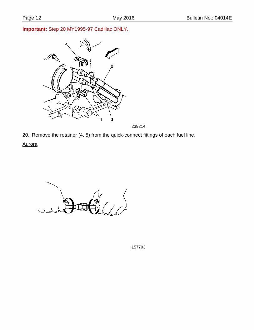
Important: Step 20 MY1995-97 Cadillac ONLY.
239214
20. Remove the retainer (4, 5) from the quick-connect fittings of each fuel line.
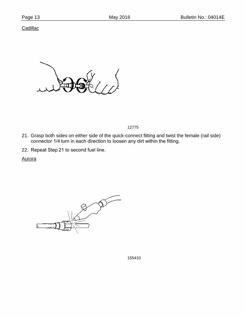
Aurora
157703
Page 13 May 2016 Bulletin No.: 04014E
Cadillac
12775
21. Grasp both sides on either side of the quick-connect fitting and twist the female (rail side) connector 1/4 turn in each direction to loosen any dirt within the fitting.
22. Repeat Step 21 to second fuel line.
Aurora
155410

Page 14 May 2016 Bulletin No.: 04014E
Cadillac
154410
23. Blow dirt out of the fittings using compressed air.
Important: Steps 24-29 MY1995-97 Cadillac ONLY.
1461176
24. Remove the fuel rail bracket nut from the EGR stud.
25. Place a shop towel below the fuel line fittings while disconnecting to avoid spillage.

Page 15 May 2016 Bulletin No.: 04014E
12780
26. Using the proper sized tool for the upper fuel line (J 37088-1, 3/8 in) from the J 37088-A tool set, insert the tool into the female connector and push in, in order to release the locking tabs.
12782
27. Pull the upper fuel line connection apart.
28. Using the proper sized tool for the lower fuel line (J 37088-2, 5/16 in) from the J 37088-A tool set, insert the tool into the female connector and push in, in order to release the locking tabs.
29. Pull the lower fuel line connection apart.
Important: Steps 30-34 MY1995-97 Aurora ONLY.
30. Place a shop towel below the fuel line fittings while disconnecting to avoid spillage.

Page 16 May 2016 Bulletin No.: 04014E
12777
31. Squeeze the plastic retainer tabs in order to release the locking tabs.
12778
32. Pull the upper fuel line connection apart.
33. Repeat Steps 31 and 32 for the lower fuel line.
34. Remove the PCV rear hose.
Important: Step 35 MY1997 Cadillac ONLY.
35. Disconnect and remove the PCV front hose.

Page 17 May 2016 Bulletin No.: 04014E
71512
36. Remove the spark plug harness retainer from the fuel injector sight shield stud.
37. Disconnect the front spark plug wires from the front spark plugs and reposition.
Important: Steps 38-41 MY1997 Cadillac ONLY.
38. Disconnect and remove the PCV front hose.
39. Disconnect and remove the brake booster hose.
40. Disconnect and remove the EVAP tube between the intake manifold adapter and the EVAP solenoid.
1461178
41. Disconnect and remove the fuel pressure regulator hose.
Important: Steps 42-47 MY 1995-97 Cadillac ONLY.
42. Disconnect the remove the PCV rear hose.
43. Disconnect the brake booster hose from the intake manifold adapter and reposition.

Page 18 May 2016 Bulletin No.: 04014E
44. Disconnect and remove the fuel pressure regulator hose.
1461180
45. Remove any retainers and pull the throttle body heater pipe off of the fuel injector sight shield studs and reposition.
46. Remove the fuel injector sight shield studs and spacers.
47. Disconnect the fuel injector wiring harness from the 8 fuel injectors and reposition the fuel injector wiring harness.
Important: Steps 48-51 MY 1995-97 Aurora ONLY.
48. Disconnect the fuel regulator hose from the fuel regulator.
95 Aurora
1463373

Page 19 May 2016 Bulletin No.: 04014E
96-97 Aurora
1461652
49. Remove the fuel rail bracket bolt from the engine lift bracket.
50. Remove the fuel injector sight shield studs and spacers.
51. Disconnect the fuel injector wiring harness from the 8 fuel injectors and reposition the fuel injector wiring harness.
1461182
52. Remove the grounding harness bolt from the front of the right (rear) cylinder head.
53. Remove the fuel rail ground harness.

Page 20 May 2016 Bulletin No.: 04014E
Notice: Use the correct fastener in the correct location. Replacement fasteners must be the correct part number for that application. Fasteners requiring replacement or fasteners requiring the use of thread locking compound or sealant are identified in the service procedure. Do not use paints, lubricants, or corrosion inhibitors on fasteners or fastener joint surfaces unless specified. These coatings affect fastener torque and joint clamping force and may damage the fastener. Use the correct tightening sequence and specifications when installing fasteners in order to avoid damage to parts and systems.
54. Reinstall the grounding harness bolt with the ECM/ignition coil ground harness. Tighten Tighten the grounding harness to 25 Nm (18 lb ft).
Aurora
1461622
Aurora
1461625
Page 21 May 2016 Bulletin No.: 04014E
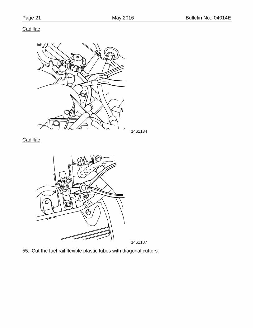
Cadillac
1461184
Cadillac
1461187
55. Cut the fuel rail flexible plastic tubes with diagonal cutters.

Page 22 May 2016 Bulletin No.: 04014E
1461192
56. Release the locking tabs holding the fuel rail to the intake manifold.
Notice:
Remove the fuel rail assembly carefully in order to prevent damage to the injector electrical connector terminals and the injector spray tips. Support the fuel rail after the fuel rail is removed in order to avoid damaging the fuel rail components.
Cap the fittings and plug the holes when servicing the fuel system in order to prevent dirt and other contaminants from entering open pipes and passages.
57. Remove the fuel rail and fuel injectors as an assembly from the intake manifold. Use the J 41801 to aid in removing any injectors stuck in the intake manifold. Place the J 41081 between the intake manifold and the bottom of the fuel injector.
1461196
Important: Step 58 MY1995-97 Cadillac ONLY.
58. In order to pull the metal fuel line out from under the intake manifold adapter, using pliers collapse the left (front) metal line tube at the right (rear) side of the intake manifold

Page 23 May 2016 Bulletin No.: 04014E
adapter. Weakening the tube will allow the left (front) metal line tube to be pulled out from under the intake manifold adapter on the right (rear) side of the intake manifold adapter.
1461197
59. Place the old fuel rail assembly on a clean, flat surface next to and in the same orientation as the new fuel rail assembly.
1995 Oldsmobile Aurora Fuel Chassis Line Removal and Installation
The following procedure is for replacing the fuel lines from the fuel rail on the engine back to and including the fuel filter under the vehicle. The new fuel lines come complete with all necessary retainers. It applies only to the 1995 Oldsmobile Aurora and is based on the fuel rail being replaced at the same time. Therefore the steps or procedures for relieving fuel pressure, disconnecting the lines from the fuel rail, etc., can be found in the fuel rail replacement section of this recall bulletin.
1461197
1. Disconnect the fuel lines (5) from the underhood retainers on the throttle body and body sheet metal (4).
2. Separate the cruise control cable from the retainer.

Page 24 May 2016 Bulletin No.: 04014E
3. Remove the retainers from the body sheet metal and throttle body and discard.
1507509
4. Using a sharp utility knife, cut off the plastic fuel lines where they meet the steel fuel lines (1) near the vacuum brake booster.
5. Disconnect the evaporative emission hose.
155531
6. Remove the two nuts that attach the ABS module to the left strut (shock) tower.
7. Remove the ABS module and disconnect the electrical connector.
8. Partially raise the vehicle on a suitable hoist and support.
9. Remove the left front tire and wheel assembly.
10. Remove the 7 push-in type retainers attaching the rear of the left front wheelhouse liner and reposition the liner as necessary to access the transmission mount and the brace connecting the body rail and the lower cowl.
11. Raise the vehicle fully.

Page 25 May 2016 Bulletin No.: 04014E
12. Support the rear of the engine frame (cradle) as necessary.
13. Remove the four rear cradle bolts.
14. Remove the two nuts attaching the left side transmission bracket to the body mount.
Notice: When lowering the cradle in the next step, pay close attention to the intermediate steering shaft between the steering gear and the steering column. Do not allow the engine and cradle to be supported by the shaft.
15. Lower the rear of the cradle as necessary.
283578
16. Remove the four bolt (4) attaching the brace (3) between the body rail (2) and the lower cowl sheet metal. Remove the brace.
13606
17. Remove the bolt attaching the fuel line retainer (2) to the lower cowl sheet metal.
18. Remove the fuel lines from that retainer.
19. From underneath the vehicle, release the four fuel line retainers (3) from the underbody.

Page 26 May 2016 Bulletin No.: 04014E
20. Unclip the fuel lines from the retainers.
21. Disconnect the fuel feed line at the quick connect on the rearward end of the fuel filter (5).
22. Disconnect the remaining two lines at the quick connects rearward (6) of the fuel filter.
23. Remove the fuel lines and all retainers from the vehicle.
Important: Do NOT bend the new fuel lines when installing in the next step.
24. Position the NEW fuel lines under the vehicle and route the engine end of the lines up into the engine compartment.
4375763
25. Install the new fuel lines and retainers to the floor pan.
Caution: In order to reduce the risk of fire and personal injury, before connecting fuel pipe fittings, always apply a few drops of clean engine oil to the male pipe ends. This will ensure proper reconnection and prevent a possible fuel leak. During normal operation, the O-rings located in the female connector will swell and may prevent proper reconnection if not lubricated.
26. Apply a few drops of clean engine oil to the male ends of the quick connect pipes.
27. Install the NEW fuel filter to the fuel line and quick connect fitting. Push both sides of the fitting together to cause the retaining tabs/fingers to snap into place. Tighten Tighten the flare nut to 30 Nm (22 lb ft).
28. Connect the remaining quick-connect fittings under the vehicle. Push both sides of the fittings together to cause the retaining tabs/fingers to snap into place.
29. Pull on both sides of all quick-connect fittings to ensure connections are secure.

Page 27 May 2016 Bulletin No.: 04014E
30. Install the fuel lines to the retainer. Position the retainer to the lower cowl sheet metal and install the bolt. Tighten Tighten the bolt to 9 Nm (7 lb ft).
31. Position the brace between the body rail and the lower cowl sheet metal. Install the four bolts. Tighten Tighten to 50 Nm (37 lb ft).
32. Raise the rear of the engine cradle and install the four bolts. Tighten Tighten to 100 Nm (74 lb ft).
33. Install the two nuts attaching the left side transmission bracket to the body mount. Tighten Tighten to 35-45 Nm (47-61 lb ft).
34. Position the left front wheelhouse liner and install the seven push-in retainers.
35. Install the left front tire and wheel. Tighten Tighten the nuts to 140 Nm (100 lb ft).
36. Lower the vehicle.
37. Connect the electrical connector to the ABS module.
38. Position the ABS module to the left strut (shock) tower and install the two nuts. Tighten Tighten to 11 Nm (96 lb in).
Caution: In order to reduce the risk of fire and personal injury, before connecting fuel pipe fittings, always apply a few drops of clean engine oil to the male pipe ends. This will ensure proper reconnection and prevent a possible fuel leak. During normal operation, the O-rings located in the female connector will swell and may prevent proper reconnection if not lubricated.
39. Apply a few drops of clean engine oil to the male ends of the quick connect pipes.
40. Connect the quick-connect fittings on the plastic tubing to the fuel lines. Push both sides of the fitting together to cause the retaining tabs/fingers to snap into place.
41. Pull on both sides of all quick-connect fittings on the plastic tubing to the fuel lines. Push both sides of the fitting together to cause the retaining tabs/fingers to snap into place.
42. Attach the fuel line retainer to the body sheet metal and throttle body.
43. Connect the cruise control cable to the retainer.
44. Attach the new evaporative emissions hose.
45. Refer to the fuel rail replacement procedure for connecting fuel liens to the fuel rail and the remainder of the recall procedure.

Page 28 May 2016 Bulletin No.: 04014E
Fuel Rail Disassembly and Assembly
190817
Notice:
Do not use compressed air to test or clean a fuel pressure regulator. Excessive air pressure can damage the fuel pressure regulator.
Do not immerse the fuel pressure regulator in a cleaning solvent in order to prevent damage to the regulator.
Use ONLY clean engine oil to lubricate O-rings. In order to prevent damage to the fuel pressure regulator, do NOT use any other type of lubricant.
1. Remove the fuel regulator from the old fuel rail assembly.
1.1 Remove the fuel pressure regulator retaining clip (3).
1.2 Lift, twist and remove the fuel rail regulator (6) from the fuel rail socket.
1537210

Page 29 May 2016 Bulletin No.: 04014E
2. Install the NEW fuel pressure regulator seals, back-up spacer and filter from the seal kit (P/N 17800050, 51, 52 or 53) onto the existing fuel pressure regulator in proper order.
2.1 Install the NEW O-ring back-up (1) onto the fuel pressure regulator.
2.2 Coat the NEW large O-ring (2) with clean engine oil and install onto the fuel regulator.
2.3 Install the NEW regulator filter screen (3) onto the fuel regulator.
2.4 Coat the NEW small O-ring (4) with clean engine oil and install onto the fuel regulator.
1537212
3. Install the fuel pressure regulator assembly into the NEW fuel rail (P/N 12583145, 46 or 47).
3.1 Insert the assembled fuel pressure regulator (1) into the fuel rail socket using a turning motion to properly seat the O-rings.
3.2 Install the NEW fuel pressure regulator retaining clip (2).
168577

Page 30 May 2016 Bulletin No.: 04014E
4. Exchange each fuel injector from the old fuel rail assembly to the NEW fuel rail assembly one at a time in order to keep each injector in its original position.
4.1 Spread and release the fuel injector clip from the old fuel rail assembly.
4.2 Remove the fuel injector assembly (1).
4.3 Remove the upper (3) and lower (2) fuel injector O-rings.
Important: Use ONLY clean engine oil to lubricate O-rings. Do NOT use any other type of lubricant or grease.
4.4 Coat with clean engine oil the NEW O-rings and install onto the fuel injector assembly.
1461203
4.5 Install the fuel injector assembly into the same location on the NEW fuel rail assembly with the wiring harness connector facing outboard direction.
1461208
4.6 Install the NEW fuel injector clip onto the NEW fuel rail assembly.
4.7 Repeat Steps 4.1 through 4.6 on the remaining fuel injectors.

Page 31 May 2016 Bulletin No.: 04014E
Important: Step 5 MY 1995-97 Aurora ONLY.
5. Transfer the plastic fuel line retainers from the old fuel rail to the NEW fuel rail.
Fuel Rail Installation
1. Place the NEW fuel rail assembly into position.
1.1 Align the fuel injectors to the fuel injector bores in the intake manifold.
1.2 Align the fuel injector assembly bracket to the engine lift bracket (Aurora); or EGR valve stud (Cadillac).
1.3 Apply pressure to fuel rail assembly to seat fuel injectors into fuel injector bores in the intake manifold.
Notice: Use the correct fastener in the correct location. Replacement fasteners must be the correct part number for that application. Fasteners requiring replacement or fasteners requiring the use of thread locking compound or sealant are identified in the service procedure. Do not use paints, lubricants, or corrosion inhibitors on fasteners or fastener joint surfaces unless specified. These coatings affect fastener torque and joint clamping force and may damage the fastener. Use the correct tightening sequence and specifications when installing fasteners in order to avoid damage to parts and systems.
Important: Steps 2-8 MY1995-97 Cadillac ONLY.
1461176
2. Install the nut retaining the fuel rail assembly bracket to the EGR stud. Tighten Tighten the nut retaining the fuel rail assembly bracket to the EGR stud to 8 Nm (71 lb in).
3. Install the fuel rail injector sight shield spacers and studs. Tighten Tighten the fuel injector sight shield studs to 12 Nm (106 lb in).

Page 32 May 2016 Bulletin No.: 04014E
1461210
4. Align the throttle body heater pipe onto the fuel injector sight shield studs and install any retainers onto the fuel injector sight shield studs.
5. Connect the fuel injector wiring harness to the 8 fuel injectors and reinstall the fuel injector wiring harness.
6. Install and connect the NEW fuel pressure regulator hose to the fuel regulator and the vacuum port of the intake manifold.
7. Install and connect the brake booster hose.
8. Install and connect the PCV rear hose.
Important: Steps 9-10 MY1997 Cadillac ONLY.
9. Install and connect the PCV front hose.
10. Install and connect the EVAP tube between the intake manifold adapter and the EVAP solenoid.
Important: Steps 11-15 MY1995-97 Aurora ONLY.
11. Install the fuel rail injector sight shield spacers and studs. Tighten Tighten the fuel rail injector sight shield studs to 12 Nm (106 lb in).

Page 33 May 2016 Bulletin No.: 04014E
95 Aurora
1463373
96-97 Aurora
1461652
12. Install the bolt retaining the fuel rail assembly bracket to the engine lift bracket. Tighten Tighten the fuel rail assembly bracket bolt to 6 Nm (53 lb in).
13. Connect the fuel injector wiring harness to the 8 fuel injectors and reinstall the fuel injector wiring harness.
14. Connect the NEW fuel regulator hose to the fuel regulator and the vacuum port on the intake manifold.
15. Install the PCV rear hose.
16. Apply dielectric grease, GM P/N 12345579 (Canadian P/N 1974984) to each spark plug boot. Route and connect the front spark plug wires to the front spark plugs.

Page 34 May 2016 Bulletin No.: 04014E
1461226
Important: Conduit installed in next step may be obtained locally if conduit ID and underhood temperature specifications are equivalent.
17. Install wire conduit, GM P/N 8919354 or equivalent, over each of the front spark plug wires where the spark plug wires lay across the fuel rail on both sides (approximately 6 feet required per vehicle).
o Between the spark plug boot and the retainer in the center of the intake manifold, add a 300 mm (12 in) section of conduit on each of the left side spark plug wires.
o Between the retainer in the center of the intake manifold and the conduit already installed, add the following sections of conduit on each left side spark plug wires:
- 230 mm (9 in) on the number 2 spark plug wire
- 150 mm (6 in) on the number 4 spark plug wire
- 110 mm (4.5 in) on the number 6 and 8 spark plug wire
Important: Step 18 MY1995-97 Aurora ONLY.
18. Install the fuel line connections.
Notice: If necessary, remove rust or burrs from the fuel pipes with an emery cloth. Use a radial motion with the fuel pipe end in order to prevent damage to the O-ring sealing surface. Use a clean shop towel in order to wipe off the male tube ends. Inspect all the connections for dirt and burrs. Clean or replace the components and assemblies as required.
19. Clean the quick-connect fittings.

Page 35 May 2016 Bulletin No.: 04014E
Aurora
155425
Cadillac
12784
Caution: In order to reduce the risk of fire and personal injury, before connecting fuel pipe fittings, always apply a few drops of clean engine oil to the male pipe ends. This will ensure proper reconnection and prevent a possible fuel leak. During normal operation, the O-rings located in the female connector will swell and may prevent proper reconnection if not lubricated.
20. Apply a few drops of clean engine oil to the male ends of the engine fuel rail inlet and outlet pipes.
Page 36 May 2016 Bulletin No.: 04014E
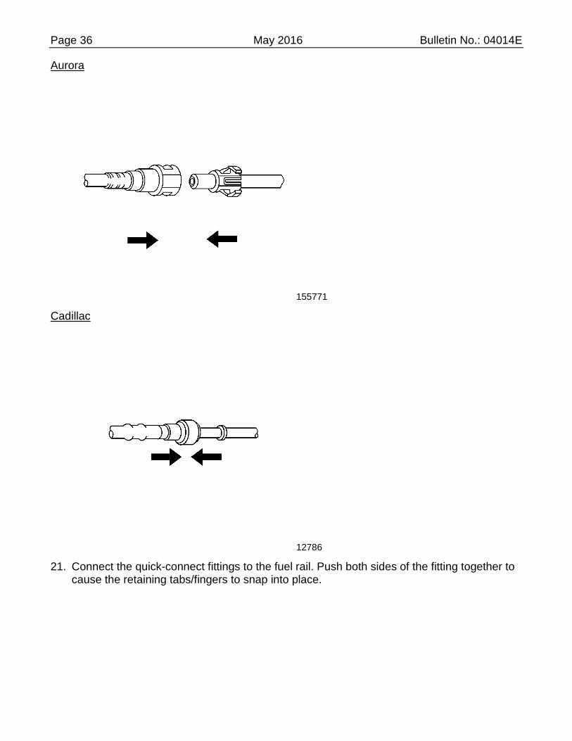
Aurora
155771
Cadillac
12786
21. Connect the quick-connect fittings to the fuel rail. Push both sides of the fitting together to cause the retaining tabs/fingers to snap into place.

Page 37 May 2016 Bulletin No.: 04014E
Aurora
155399
Cadillac
12787
22. Pull on both sides of the fitting to ensure connection is secure once installed.
Page 38 May 2016 Bulletin No.: 04014E
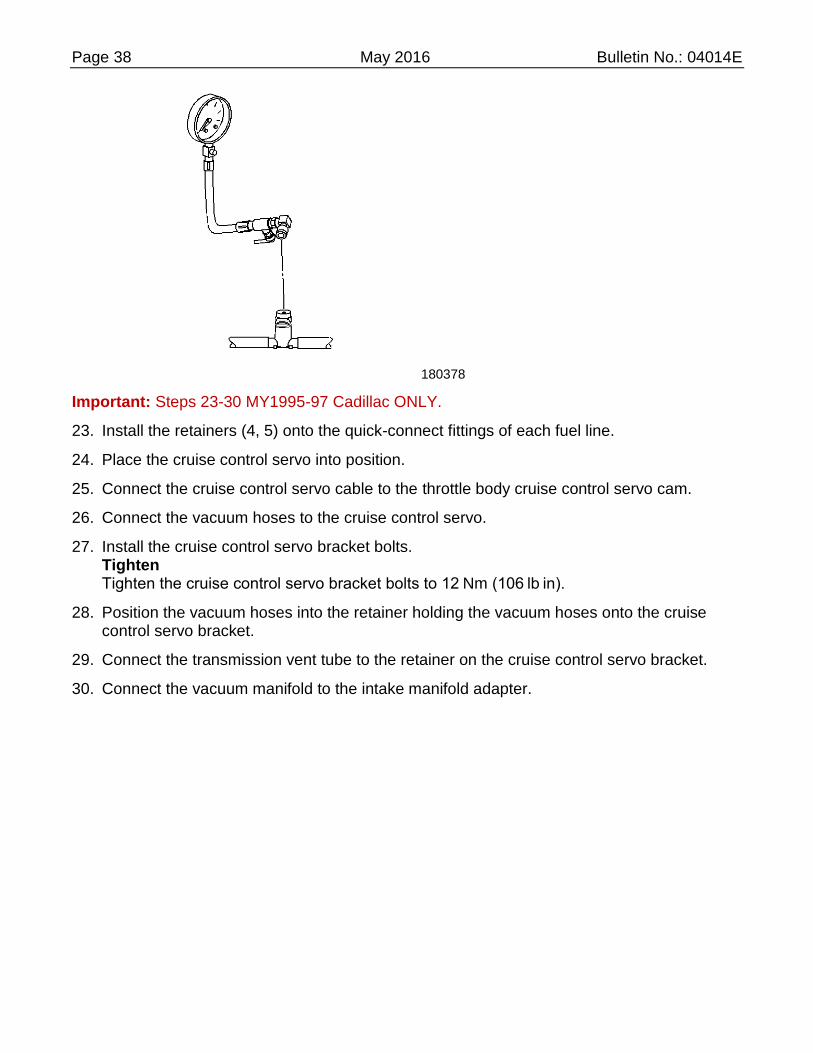
180378
Important: Steps 23-30 MY1995-97 Cadillac ONLY.
23. Install the retainers (4, 5) onto the quick-connect fittings of each fuel line.
24. Place the cruise control servo into position.
25. Connect the cruise control servo cable to the throttle body cruise control servo cam.
26. Connect the vacuum hoses to the cruise control servo.
27. Install the cruise control servo bracket bolts. Tighten Tighten the cruise control servo bracket bolts to 12 Nm (106 lb in).
28. Position the vacuum hoses into the retainer holding the vacuum hoses onto the cruise control servo bracket.
29. Connect the transmission vent tube to the retainer on the cruise control servo bracket.
30. Connect the vacuum manifold to the intake manifold adapter.

Page 39 May 2016 Bulletin No.: 04014E
Aurora
228002
Cadillac
48462
Page 40 May 2016 Bulletin No.: 04014E
31. Connect the negative battery cable.
32. Tighten the negative cable bolt at the battery. Tighten Tighten the negative cable bolt to 15 Nm (11 lb ft).
33. Check for fuel leaks.
33.1 Turn the ignition switch ON for 2 seconds.
33.2 Turn the ignition switch OFF for 10 seconds.
33.3 Turn the ignition switch ON.
33.4 Check for fuel leaks.
33.5 Start the vehicle and allow engine to reach operating temperature while observing for fuel leaks.
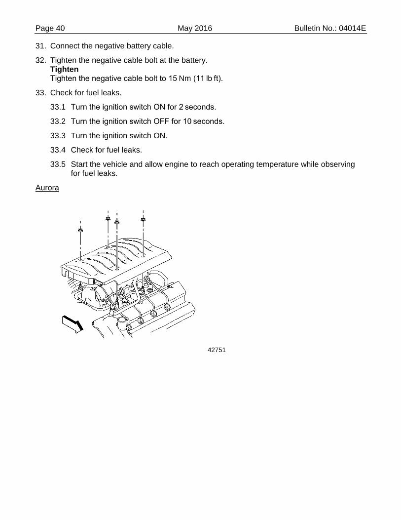
Aurora
42751

Page 41 May 2016 Bulletin No.: 04014E
Cadillac
20426
34. Install the fuel injector sight shield.
35. Install the 4 fuel injector sight shield nuts. Tighten Tighten the fuel injector sight shield nuts to 3 Nm (27 lb in).
36. Close the hood and reset the customer's radio setting.
CUSTOMER REIMBURSEMENT - For US
All customer requests for reimbursement for previous repairs for the recall condition will be handled by the Customer Assistance Center, not by dealers.
A General Motors Product Recall Customer Reimbursement Procedure Form is included with the customer letter.
Important: Refer to the GM Service Policies and Procedures Manual, section 6.1.12, for specific procedures regarding customer
Page 42 May 2016 Bulletin No.: 04014E
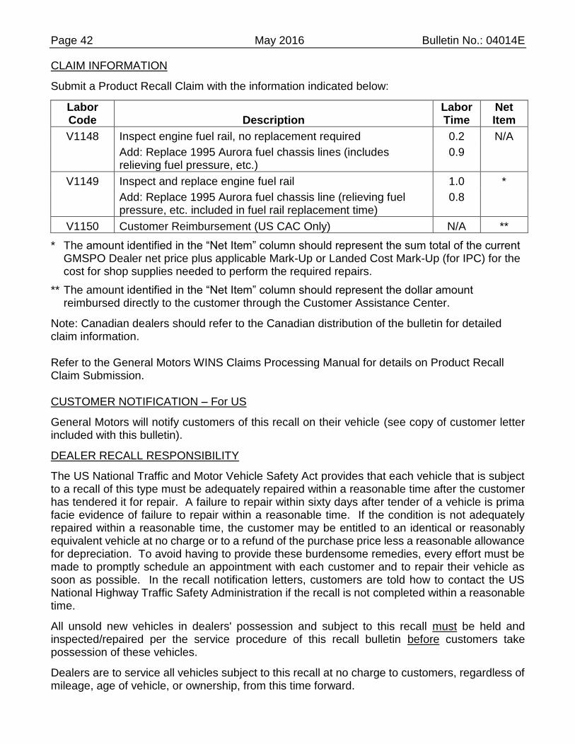
CLAIM INFORMATION
Submit a Product Recall Claim with the information indicated below:
Labor Code Description
Labor Time
Net Item
V1148 Inspect engine fuel rail, no replacement required 0.2 N/A
Add: Replace 1995 Aurora fuel chassis lines (includes relieving fuel pressure, etc.)
0.9
V1149 Inspect and replace engine fuel rail 1.0 *
Add: Replace 1995 Aurora fuel chassis line (relieving fuel pressure, etc. included in fuel rail replacement time)
0.8
V1150 Customer Reimbursement (US CAC Only) N/A **
* The amount identified in the “Net Item” column should represent the sum total of the current GMSPO Dealer net price plus applicable Mark-Up or Landed Cost Mark-Up (for IPC) for the cost for shop supplies needed to perform the required repairs.
** The amount identified in the “Net Item” column should represent the dollar amount reimbursed directly to the customer through the Customer Assistance Center.
Note: Canadian dealers should refer to the Canadian distribution of the bulletin for detailed claim information.
Refer to the General Motors WINS Claims Processing Manual for details on Product Recall Claim Submission.
CUSTOMER NOTIFICATION – For US
General Motors will notify customers of this recall on their vehicle (see copy of customer letter included with this bulletin).
DEALER RECALL RESPONSIBILITY
The US National Traffic and Motor Vehicle Safety Act provides that each vehicle that is subject to a recall of this type must be adequately repaired within a reasonable time after the customer has tendered it for repair. A failure to repair within sixty days after tender of a vehicle is prima facie evidence of failure to repair within a reasonable time. If the condition is not adequately repaired within a reasonable time, the customer may be entitled to an identical or reasonably equivalent vehicle at no charge or to a refund of the purchase price less a reasonable allowance for depreciation. To avoid having to provide these burdensome remedies, every effort must be made to promptly schedule an appointment with each customer and to repair their vehicle as soon as possible. In the recall notification letters, customers are told how to contact the US National Highway Traffic Safety Administration if the recall is not completed within a reasonable time.
All unsold new vehicles in dealers' possession and subject to this recall must be held and inspected/repaired per the service procedure of this recall bulletin before customers take possession of these vehicles.
Dealers are to service all vehicles subject to this recall at no charge to customers, regardless of mileage, age of vehicle, or ownership, from this time forward.

Page 43 May 2016 Bulletin No.: 04014E
Customers who have recently purchased vehicles sold from your vehicle inventory, and for which there is no customer information indicated on the dealer listing, are to be contacted by the dealer. Arrangements are to be made to make the required correction according to the instructions contained in this bulletin. A copy of the customer letter is provided in this bulletin for your use in contacting customers. Recall follow-up cards should not be used for this purpose, since the customer may not as yet have received the notification letter.
In summary, whenever a vehicle subject to this recall enters your vehicle inventory, or is in your dealership for service in the future, you must take the steps necessary to be sure the recall correction has been made before selling or releasing the vehicle.
GM bulletins are intended for use by professional technicians, NOT a "do-it-yourselfer". They are written to inform these technicians of conditions that
may occur on some vehicles, or to provide information that could assist in the proper service of a vehicle. Properly trained technicians have the tools,
equipment, safety instructions, and know-how to do a job properly and safely. If a condition is described, DO NOT assume that the bulletin applies to
your vehicle, or that your vehicle will have that condition. See your dealer for information on whether your vehicle may benefit from the information.
We Support
Voluntary Technician
Certification

Page 44 May 2016 Bulletin No.: 04014E
October 2004
Dear General Motors Customer:
This notice is sent to you in accordance with the requirements of the National Traffic and Motor Vehicle Safety Act. Federal regulation requires that any vehicle lessor receiving this recall notice must forward a copy of this notice to the lessee within ten days.
Reason For This Recall: General Motors has decided that a defect which relates to motor vehicle safety exists in all 1995-1997 Cadillac DeVille Concours, Seville, Eldorado, 1996-97 Cadillac DeVille; and 1995-1997 Oldsmobile Aurora model vehicles. These vehicles have a condition in which the original equipment nylon tubing used in the fuel rail construction may degrade and crack. Additionally, the 1995 Oldsmobile Aurora uses a unique underhood fuel return line that may crack at unusually high rates. Cracking of the fuel rail can result in a fuel leak into the engine compartment. The operator may experience fuel odor and possibly engine stalling due to loss of fuel pressure to the engine. If this event were to occur, and if an ignition source were present, an engine compartment fire could occur.
What Will Be Done: Your dealer will inspect and, if necessary, replace the engine fuel rail with a new stainless steel fuel rail. Oldsmobile dealers will also replace the chassis fuel lines on 1995 Oldsmobile Aurora model vehicles. This service will be performed for you at no charge.
How Long Will The Repair Take: This service correction will take approximately one hour, and the service correction for the 1995 Oldsmobile Aurora will take an additional 50 minutes. However, due to service scheduling requirements, your dealer may need your vehicle for a longer period of time.
Contacting Your Dealer: To limit any possible inconvenience, we recommend that you contact your Oldsmobile dealer as soon as possible to schedule an appointment for this repair. By scheduling an appointment, your dealer can ensure that the necessary parts will be available on your scheduled appointment date. Should your dealer be unable to schedule a service date within a reasonable time, you should contact the appropriate Customer Assistance Center at the number listed below.
Division Number Text Telephones
(TTY)
Oldsmobile 1-800-630-6537 1-800-833-6537
Cadillac 1-866-982-2339 1-800-833-2622
Puerto Rico – English 1-800-496-9992
Puerto Rico – Español 1-800-496-9993
Virgin Islands 1-800-496-9994
If, after contacting the appropriate customer assistance center, you are still not satisfied that we have done our best to remedy this condition without charge and within a reasonable time, you may wish to write the Administrator, National Highway Traffic Safety Administration, 400 Seventh Street SW, Washington, DC 20590 or call 1-888-327-4236.
Customer Reply Form: The enclosed customer reply form identifies your vehicle. Presentation of this form to your dealer will assist in making the necessary correction in the shortest possible time. If you no longer own this vehicle, please let us know by completing the form and mailing it back to us.

Page 45 May 2016 Bulletin No.: 04014E
Customer Reimbursement: The enclosed form explains what reimbursement is available and how to request reimbursement if you have paid for repairs for the recall condition.
Recall Information Online: More information about this recall (including answers to frequently asked questions) is available online at the Owner Center at My GMLink. This free online service offers vehicle and ownership related information and tools tailored to your specific vehicle. To join, visit www.mygmlink.com and enter your vehicle's 17-character vehicle identification number (VIN) shown on the enclosed form to get the most personalized information for your vehicle. We are sorry to cause you this inconvenience; however, we have taken this action in the interest of your safety and continued satisfaction with our products.
General Motors Corporation
Enclosure 04014B

Page 46 May 2016 Bulletin No.: 04014E
GENERAL MOTORS PRODUCT PROGRAM CUSTOMER REIMBURSEMENT PROCEDURE
If you have paid to have this recall condition corrected prior to receiving this notification, you may be eligible to receive reimbursement.
Requests for reimbursement may include parts, labor, fees and taxes. Reimbursement may be limited to the amount the repair would have cost if completed by an authorized General Motors dealer. Your claim will be acted upon within 60 days of receipt.
If your claim is:
Approved, you will receive a check from General Motors.
Denied, you will receive a letter from General Motors with the reason(s) for the denial, or
Incomplete, you will receive a letter from General Motors identifying the documentation that is needed to complete the claim and offered the opportunity to resubmit the claim when the missing documentation is available.
Please follow the instructions on the Claim Form provided on the reverse side to file a claim for reimbursement. If you have questions about this reimbursement procedure, please call the toll-free telephone number provided at the bottom of the form. If you need assistance with any other concern, please contact the appropriate Customer Assistance Center at the number listed below. The Customer Assistance Center hours of operation are from 8:00 AM – 11:00 PM eastern standard time Monday through Friday.
Division Number Text Telephones (TTY)
Oldsmobile 1-800-630-6537 1-800-833-6537
Cadillac 1-866-982-2339 1-800-833-2622
Puerto Rico – English 1-800-496-9992
Puerto Rico - Español 1-800-496-9993
Virgin Islands 1-800-496-9994

Page 47 May 2016 Bulletin No.: 04014E
GENERAL MOTORS PRODUCT PROGRAM CUSTOMER REIMBURSEMENT CLAIM FORM
THIS SECTION TO BE COMPLETED BY THE CLAIMANT
Date Claim Submitted:
17-Digit Vehicle Identification Number (VIN):
Mileage at Time of Repair:
Date of Repair:
Claimant Name (please print):
Street Address or PO Box Number:
City, State, ZIP Code:
Daytime Telephone Number (include Area Code):
Evening Telephone Number (include Area Code):
Amount of Reimbursement Requested: $
THE FOLLOWING DOCUMENTATION MUST ACCOMPANY THIS CLAIM FORM Original or clear copy of all receipts, invoices and/or repair orders that show:
The name and address of the person who paid for the repair.
The Vehicle Identification Number (VIN) of the vehicle that was repaired.
What problem occurred, what repair was done, when it was done and who did it.
The total cost of the repair expense that is being claimed.
Payment for the repair in question and the date of payment.
(copy of front and back of cancelled check, or copy or credit card receipt.)
My signature to this document attests that all attached documents are genuine and I request reimbursement for the expense I incurred for the repair covered by this special policy.
Claimant's Signature:

Page 48 May 2016 Bulletin No.: 04014E
Please mail this claim form and the required documents to:
General Motors Corporation
P.O. Box 33170
Detroit, MI 48232-5170
All recall reimbursement questions should be directed to the following number: 1-800-204-0261.