by marcus o. durham, karen d. durham,by marcus o. durham, karen d. durham, & robert a. durham...
TRANSCRIPT
31
IEE
EIN
DU
ST
RY
AP
PL
ICA
TIO
NS
MA
GA
ZIN
E•
SE
PT
|O
CT
20
02
•W
WW
.IEE
E.O
RG
/IA
S
B Y M A R C U S O . D U R H A M ,
K A R E N D . D U R H A M ,
& R O B E R T A . D U R H A M
RANSIENT-VOLTAGE SURGE
SUPPRESSION (TVSS) is a very neces-
sary ingredient for most electronic and
computer devices that are exposed to tele-
communications or power lines. Nevertheless, effective ap-
plication, design, and manufacturing still tends to be more
art than science. We have conducted over 100 tests of various
commercial devices. As a part of the project, the design of effec-
tive devices was pursued. Fortunately, the best devices are actu-
ally quite inexpensive.
T
A performance evaluationof TRANSIENT-VOLTAGE SURGESUPPRESSION designs.
1077-2618/02/$17.00©2002 IEEE
©C
OM
ST
OC
K,I
NC
.199
8

The purpose of the TVSS application influences the de-sign. This may be to clamp voltage, shunt current, filterfrequency, dissipate energy, or a combination. The ele-ments may consist of air gaps, passive elements, or semi-conductor electronics. Verification and performancetesting is an area often overlooked. Proper installation, in-cluding grounding, is critical to the success of the circuit.
There are numerous devices on the market that make var-ious claims. Most standards and traditional works addressclassical lightning arrester protection without detailed con-siderations of component design [1]-[5]. Most engineers donot have the instrumentation, equipment,laboratory, or resources to validate thesedevices for their applications. This articlewill discuss various approaches to protec-tion system design. Numerous differentcomponents and systems were tested as afollow-up and result of research for severalprevious grounding papers [6]-[8]. Inade-quate protection can result in equipmentfailure and downtime. Both cause lost rev-enue. Conversely, proper protection im-proves the bottom line.
ANSI Standard WaveformsDetermination of the current capacity and wave response ofprotection networks requires very sophisticated laboratoryinstruments. Any comparison requires a standardized testprocedure. ANSI C62 describes the industry-acceptedwaveform, applications, and test procedures [9]-[12].
A 1.2/50 wave-shape is used to evaluate open circuit orvoltage responses. This is shown as channel 1 (volts) of theoscillographs. For short circuit or current responses, an8/20 wave-shape is used. This is channel 2 (amps). Some os-cillograph traces show an output voltage from inline de-vices on a third channel.
A 1.2/50 wave-shape describes an impulse signal thatrises from virtually zero to its crest in 1.2 µs and declines toone-half crest value in 50 µs. The microsecond units are notusually applied to the designation of the wave.
Fig. 1. is a standard voltage waveform in response to anopen circuit. The voltage peaks and dissipates in the stan-dard period of time. There is no current flow.
Fig. 2. is the response to a short circuit. The voltage isvery limited, while the current peaks and dampens veryquickly with a very minor ringing or oscillation.
The test equipment applied both of these signals to thecircuit. The resulting wave-shape was displayed and cap-tured on a quad-channel digital recording oscilloscope.
The maximum deliverable voltage is selected prior tothe test. After firing, the voltage and current maximumand minimums that passed through the suppressor werecaptured.
Protection DevicesProtection devices are added to an electrical system to aidin managing surges. The devices may shunt current, block
energy from traveling down the wire, fil-ter certain frequencies, clamp voltagelevels, or perform a combination of thesetasks [7].
Protection devices are selected basedon the voltage, frequency, exposure, andground system of the circuit. Regardlessof the function, only a few basic compo-nents are available to economically pro-tect an electrical system. Fig. 3 shows acomplete system with all types of com-ponents.
The simplest protection arrangementis physical separation. Gaps may be used
to provide arc paths above a certain level. These may be airgaps or may have a dielectric material between conductors.Classical lightning arresters fit in this category. The crosssymbols in Fig. 3 represent these components.
Often the devices are built so that the path will be-come low impedance once breakdown occurs. Siliconcarbide (SiC) is traditionally used in high-energy de-vices [10], [13].
32
IEE
EIN
DU
ST
RY
AP
PL
ICA
TIO
NS
MA
GA
ZIN
E•
SE
PT
|O
CT
20
02
•W
WW
.IE
EE
.OR
G/
IAS
–200
0
200
400
600
800
1,000
–10 0 10 20 30 40–200
–100
0
100
200
300
400
500
Vol
ts
Am
ps
Standard 1.2/50 voltage.
1
500 500
400 400
300300
200200
100100
0
0
–100
–100
–200
Vol
ts
Am
ps
–10 0 10 20 30 40
Standard 8/20 current.
2
Protection scheme.
3
THE PURPOSEOF TVSS
APPLICATIONDETERMINES THE
DESIGN.
One brand uses a unique insulation material. It is essen-tially sand with spaced out probes. This device providesvirtually no protection.
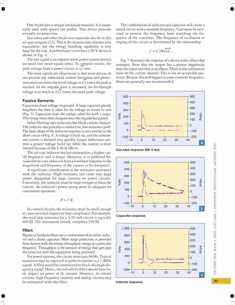
Gas tubes and other break-over materials also fit in thisair-gap category [12]. This is the slowest class of protectionequipment, but the energy handling capability is verylarge for the cost. A performance curve for a 120-V device isshown in Fig. 4.
The test signal is an impulse while power system devicesare rated root mean square (rms). To compare results, thepeak voltage from a power circuit is 2 rms.
The most significant observation is that most devices donot provide any substantial current limitation and protec-tion until two times the rated voltage or 2 times the peak isreached. As the impulse level is increased, the let-throughvoltage is as much as 2 2 times the rated peak voltage.
Passive ElementsCapacitors shunt voltage to ground. A large capacitor greatlylengthens the time it takes for the voltage to return to zero(Fig. 5). Capacitors store the energy when hit with a surge.The energy must then dissipate once the impulse has passed.
Inline filtering uses inductors that block current changes.The inductor also provides a conductive, low resistance path.The basic shape of the inductor response is very similar to theshort circuit of Fig. 6. A voltage is built up, and the substan-tial current is damped very quickly. Larger inductance per-mits a greater voltage build up, while the current is morelimited because of the L di/dt effects.
The air-core inductor has less attenuation, a higher cut-off frequency, and is larger. However, it is preferred be-cause ferrite-core inductors have a nonlinear response to themagnitude and frequency of the current to be dissipated.
A significant consideration is the resistance associatedwith the inductor. High resistance can cause very largepower dissipation for large currents on power circuits.Conversely, the inductor must be large enough to limit thecurrent. An inductor’s power rating must be adequate forcontinuous operation.
P I R= 2 .
In control circuits, the resistance must be small enoughto cause minimal impact on loop compliance. For example,the total loop resistance for a 4-20-mA circuit is typically600 Ω. The instrument already comprises 250 Ω.
FiltersBypass or bandpass filters are a combination of an inline induc-tor and a shunt capacitor. More surge protection is providedfrom devices with the lowest throughput energy at a particularfrequency. Throughput is the amount of energy that gets pastthe protector onto the equipment being protected.
For power systems, the circuit must pass 60 Hz. Typicaltransients may be expected to perform similar to a 1-MHzsignal. A filter would be constructed to block this high-fre-quency signal. Hence, the roll-off of a filter should have lit-tle impact on power or dc circuits. However, in controlcircuits, high frequency counters and analog circuits maybe attenuated with this filter.
The combination of inductor and capacitor will create atuned circuit with a resonant frequency. Care must be exer-cised to prevent the frequency from matching the fre-quency of the transients. The frequency of oscillation orringing of the circuit is determined by the relationship
f LC=1 2π .
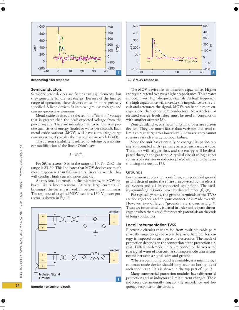
Fig. 7 illustrates the response of a device with a filter thatresonates. Note that the output has a greater magnitudethan the input and that it oscillates. There is also substantialnoise on the current channel. This is not an acceptable pro-tector. Because this will happen at some transient frequency,filters are generally not recommended.
33
IEE
EIN
DU
ST
RY
AP
PL
ICA
TIO
NS
MA
GA
ZIN
E•
SE
PT
|O
CT
20
02
•W
WW
.IEE
E.O
RG
/IA
S
Gas tube response 500-V test.
4
Capacitor response.
5
–200
0
200
400
600
800
1,000
–10 0 10 20 30 40–200
–100
0
100
200
300
400
500
Vol
ts
Am
ps
Inductor response.
6
SemiconductorsSemiconductor devices are faster than gap elements, butthey generally handle less energy. Because of the limitedrange of operation, these devices must be more preciselyspecified. Silicon devices fit into two groups: voltage- andcurrent-protective elements.
Metal-oxide devices are selected for a “turn on” voltagethat is greater than the peak expected voltage from thepower supply. They are manufactured to handle very pre-cise quantities of energy (joules or watts per second). Eachmetal-oxide varistor (MOV) will have a resulting surgecurrent rating. Typically the material is zinc oxide (ZnO).
The current capability is related to voltage by a nonlin-ear modification of the linear Ohm’s law
I kV= α .
For SiC arresters, α is in the range of 10. For ZnO, therange is 25-60. This indicates that MOV devices are muchmore responsive than SiC arresters. In other words, theywill conduct high current more quickly.
At very small currents, in the microamps, an MOV be-haves like a linear resistor. At very large currents, inkiloamps, the current is fixed. In between, it is nonlinear.The response of a typical MOV used in a 130-V power pro-tector is shown in Fig. 8.
The MOV device has an inherent capacitance. Higherenergy units tend to have a higher capacitance. This createsa problem with high-frequency signals. At high frequency,the high capacitance will increase the impedance of the cir-cuit and attenuate the signal. MOVs can handle more en-ergy alone than other semiconductors. Nevertheless, atelevated energy levels, they must be used in conjunctionwith another arrester [8].
Zener, avalanche, or silicon junction diodes are currentdevices. They are much faster than varistors and tend tolimit voltage surges to a lower level. However, they cannotsustain as much energy without failure.
Since the unit has essentially no energy dissipation rat-ing, it is coupled with a primary arrester such as a gas tube.The diode will trigger first, and the energy will be dissi-pated through the gas tube. A typical circuit using a zenerconsists of a resistor or inductor placed inline and the zenershunting the output [7].
GroundsFor transient protection, a uniform, equipotential groundgrid is desired under the entire area covered by the electri-cal system and all its connected equipment. The facil-ity-grounding network provides this reference [6]-[8].
For typical systems, the ground terminals of the TVSSare tied together, and only one connection is made to earth.However, two different “grounds” are shown in Fig. 9.These are intentionally isolated in order to dissipate the en-ergy or when there are different earth potentials on the endsof long conductors.
Local Instrumentation TVSSElectronic circuits that are fed from multiple cable pairsshare the surge energy between the pairs; therefore, less en-ergy is imposed on each piece of electronics. The mode ofprotection depends on the connection of the protection cir-cuit. Differential-mode units are connected between thetwo signal wires of a circuit. A common-mode unit is con-nected between a signal wire and ground.
Where a common ground is available, as a minimum, acommon-mode device should be placed on both ends ofeach conductor. This is shown in the top part of Fig. 9.
Many commercial protection modules have differentialprotection and an inductor to limit current changes. Theseinductors detrimentally impact the impedance and fre-quency response of the circuit.34
IEE
EIN
DU
ST
RY
AP
PL
ICA
TIO
NS
MA
GA
ZIN
E•
SE
PT
|O
CT
20
02
•W
WW
.IE
EE
.OR
G/
IAS
–200
0
200
400
600
800
1,000
–10 0 10 20 30 40–200
–100
0
100
200
300
400
500
Vol
ts
Am
ps
Resonating filter response.
7
500 500
400 400
300300
200200
100100
0
0
–100
–100
–200–10 0 10 20 30 40
Vol
ts
Am
ps
130-V MOV response.
8
Isolated SignalGround
+ +
++
– –
––
s
s
xmitter
xmitter
Remote transmitter circuit.
9
Most commercial units have a common-mode connec-tion to the earth. While this may be acceptable inside theplant ground grid area, it often contributes to failures ontransmitters remote from the signal power source, becauseof circulating currents.
Remote Instrumentation TVSSFor remote instrumentation, the primary requirement is toisolate the unshielded cable from both the transmitter andthe distributed control system (DCS) input card. Isolatedinline protectors should be placed on the transmitter usingdifferential mode. Shunt devices should be placed on theDCS ends of the cables using common mode.
A very effective inductor is 20 turns of the circuit wire.This should be on an air core that has a radius at least seventimes the wire diameter. For typical instrumentation wire,this can be wrapped around a pencil for shape.
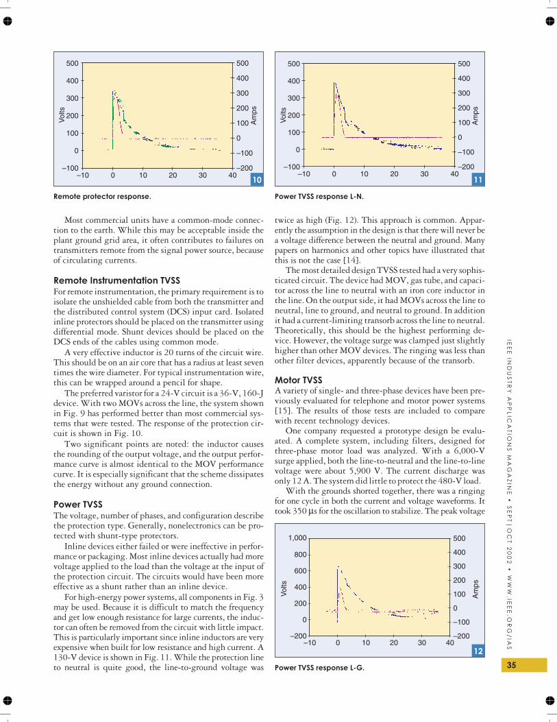
The preferred varistor for a 24-V circuit is a 36-V, 160-Jdevice. With two MOVs across the line, the system shownin Fig. 9 has performed better than most commercial sys-tems that were tested. The response of the protection cir-cuit is shown in Fig. 10.
Two significant points are noted: the inductor causesthe rounding of the output voltage, and the output perfor-mance curve is almost identical to the MOV performancecurve. It is especially significant that the scheme dissipatesthe energy without any ground connection.
Power TVSSThe voltage, number of phases, and configuration describethe protection type. Generally, nonelectronics can be pro-tected with shunt-type protectors.
Inline devices either failed or were ineffective in perfor-mance or packaging. Most inline devices actually had morevoltage applied to the load than the voltage at the input ofthe protection circuit. The circuits would have been moreeffective as a shunt rather than an inline device.
For high-energy power systems, all components in Fig. 3may be used. Because it is difficult to match the frequencyand get low enough resistance for large currents, the induc-tor can often be removed from the circuit with little impact.This is particularly important since inline inductors are veryexpensive when built for low resistance and high current. A130-V device is shown in Fig. 11. While the protection lineto neutral is quite good, the line-to-ground voltage was
twice as high (Fig. 12). This approach is common. Appar-ently the assumption in the design is that there will never bea voltage difference between the neutral and ground. Manypapers on harmonics and other topics have illustrated thatthis is not the case [14].
The most detailed design TVSS tested had a very sophis-ticated circuit. The device had MOV, gas tube, and capaci-tor across the line to neutral with an iron core inductor inthe line. On the output side, it had MOVs across the line toneutral, line to ground, and neutral to ground. In additionit had a current-limiting transorb across the line to neutral.Theoretically, this should be the highest performing de-vice. However, the voltage surge was clamped just slightlyhigher than other MOV devices. The ringing was less thanother filter devices, apparently because of the transorb.
Motor TVSSA variety of single- and three-phase devices have been pre-viously evaluated for telephone and motor power systems[15]. The results of those tests are included to comparewith recent technology devices.
One company requested a prototype design be evalu-ated. A complete system, including filters, designed forthree-phase motor load was analyzed. With a 6,000-Vsurge applied, both the line-to-neutral and the line-to-linevoltage were about 5,900 V. The current discharge wasonly 12 A. The system did little to protect the 480-V load.
With the grounds shorted together, there was a ringingfor one cycle in both the current and voltage waveforms. Ittook 350 µs for the oscillation to stabilize. The peak voltage
35
IEE
EIN
DU
ST
RY
AP
PL
ICA
TIO
NS
MA
GA
ZIN
E•
SE
PT
|O
CT
20
02
•W
WW
.IEE
E.O
RG
/IA
S
500 500
400 400
300300
200200
100100
0
0
–100
–100
–200–10 0 10 20 30 40
Vol
ts
Am
ps
Remote protector response.
10
500 500
400 400
300300
200200
100100
0
0
–100
–100
–200–10 0 10 20 30 40
Vol
ts
Am
ps
Power TVSS response L-N.
11
–200
0
200
400
600
800
1,000
–10 0 10 20 30 40–200
–100
0
100
200
300
400
500
Vol
ts
Am
ps
Power TVSS response L-G.
12
was 5,679 V with a current of 544 A. It is very obvious thatcommon grounds can cause a coupling back to the filter.
A pure resistive load was applied to the output. Thiscaused harmonic spikes every 10 µs. This reflects the earlierdiscussion of sensitivity of the filter to tuned frequencies.
After a number of different scenarios, a very interestingobservation was found; a TVSS with MOV arresters was aseffective for a 60-Hz, 480-VAC circuit as the circuit withfilters. In a more advanced design, primary arresters en-hance the ability of the MOV to sustain large surges.
TVSS Challenges
Follow-ThroughWhen a protector device fires, the arrester will continueconducting for an extended time. The protector shorts thecircuit during the triggered time. Consequently, the sys-tem experiences false alarms and shutdowns. Gas tubes areparticularly susceptible to this problem and may nevershut-off. Specific arc-extinguishing circuits are required.By comparison, zener diodes clear very quickly whileMOVs may take up to 15 s to clear.
DegradationAn MOV degrades with time as it ages from taking surges.Manufacturers grade MOVs on the amount of energy theMOV can withstand after so many hits. Select devices withthe desired energy rating with a lifetime hit to exceed100,000. As long as a zener’s range is not exceeded, the de-vice does not significantly age. However, because of thevery limited current capability, a zener without a primaryarrester will fail often.
CatastropheSilicon semiconductors, MOVs, and gas tubes will fail in ashorted mode when at the end of their life or when over-powered. At very excessive power levels, the device maymelt and become an open circuit. Open circuits are seldomfound until the device did not do its job. For gas tubes, theopen occurs at power levels that deteriorate the elements sothe gas will not ignite. Properly designed gas tube circuitscan work to the limits of lightning levels.
RepresentativeA variety of TVSS devices were used. After analyzing theliterature, it was determined the devices fit a particular de-sign. During tests, the shape of the waveforms could usu-ally be used to determine the circuits, even in potted units.Therefore, the results of the analyses appear to be represen-tative of the state of the art.
SummaryThere are numerous different considerations for each type ofsystem. Nevertheless, there is a key concern for each. Thegoal is to make these seemingly conflicting requirementscompatible. A complete TVSS system consists of shunt pro-tectors on the input and output. Other components may in-clude the input shunted with a capacitor and an inductorplaced inline. The grounds are isolated on the input and out-put. For low energy systems, an MOV is often the only de-vice used. This may be effective if it is adequately sized and
has not deteriorated. For circuits exposed to higher energyand for power circuits, another primary arrester should beincluded. The fastest system uses avalanche diodes with aprimary arrester to dissipate the larger energy.
For adequate protection, three conditions are critical. Asemiconductor device is required. A high-energy primaryarrester is used in conjunction. The configuration is ar-ranged for all possible scenarios.
Finally, protection will generally be inappropriatewithout a very effective ground grid.
References[1] R.T. Hasbrouck, “Lightning—Understanding it and protecting sys-
tems from its effects,” Lawrence Livermore National Laboratory,
Livermore, CA, Tech. Rep. UCRL-53925, 1989.
[2] Lightning Protection Code, ANSI/NFPA 780, 2001.
[3] IEEE Recommended Practice for Grounding of Industrial and Com-
mercial Power Systems (Green Book), ANSI/IEEE Std142, 1991.
[4] IEEE Recommended Practice for Powering and Grounding Sensitive
Electronic Equipment (Emerald Book), ANSI/IEEE Std1100-1992.
[5] National Electrical Code, ANSI/NFPA 70, 2002.
[6] M.O. Durham and R. Durham, “Grounding system design for iso-
lated locations and plant systems,” IEEE Trans. Ind. Applicat., vol.
33, pp. 374-382, Mar./Apr. 1997.
[7] M.O. Durham and R.Durham, “Lightning, grounding, and protec-
tion for control systems,” IEEE Trans. Ind. Applicat., vol. 31, pp.
45-54, Jan./Feb. 1995.
[8] M.O. Durham and R.A. Durham, “Interaction and design of
grounded systems for tanks and vessels,” in Proc. IEEE Petroleum
and Chemical Industry Conf., 1999, pp. 195-202.
[9] IEEE Standard for Gapped Silicon-Carbide Surge Arresters for AC
Power Circuits, ANSI/IEEE Std C62.1-1989.
[10] IEEE Guide for the Application of Gapped Silicon-Carbide Surge Ar-
resters for Alternating Current Systems, ANSI/IEEE Std C62.2-1987.
[11] IEEE Guide for the Connection of Surge Arresters to Protect Insu-
lated, Shielded Electric Power Cable Systems, ANSI/IEEE Std
C62.22.1-1996.
[12] IEEE Standard Test Specification for Gas-Tube Surge Protective De-
vices, ANSI/IEEE Std C62.31-1987.
[13] Distribution System Protection Manual. Canonsburg, PA: McGraw
Edison.
[14] M.O. Durham, R.D. Strattan, and D. Carter, “Harmonic impact on
power system design,” Int. J. Power and Energy Syst., vol. 203, p.
1012, Feb. 1994.
[15] R. Sharma, “Transient voltage surge suppression analysis,” M.S.
thesis, Dept. Elect. Eng., Univ. of Tulsa, Tulsa, OK, 1996.
[16] D. Fink and W. Beaty, Standard Handbook for Electrical Engineers,
13th ed. New York: McGraw Hill, 1993.
[17] J. Rowland, Linear Control Systems. New York: Wiley, 1986.
Marcus O. Durham ([email protected]) is with THEWAY Corp.in Tulsa, Oklahoma, USA. Karen D. Durham is with NATCOin Tulsa, Oklahoma, USA. Robert A. Durham is with D2 Tech-nology in Broken Arrow, Oklahoma, USA. M. Durham is a Fel-low of the IEEE. K. Durham and R. Durham are members of theIEEE. This article first appeared in its original format at the 2000IEEE Petroleum and Chemical Industry Technical Conference.36
IEE
EIN
DU
ST
RY
AP
PL
ICA
TIO
NS
MA
GA
ZIN
E•
SE
PT
|O
CT
20
02
•W
WW
.IE
EE
.OR
G/
IAS