c-dias ipc with lx800 and vm 052 · in display d1, 05 is shown and in display d2, the version...
TRANSCRIPT

C-DIAS IPC WITH LX800 AND VM 052
12.10.2017 Page 1
C-DIAS IPC with LX800 and VM 052 Compact DIAS
Industrial
Personal
Computer The C-IPC is a C-DIAS industrial PC with an AMD Geode LX800 processor. A 7-segment display and 3 status LEDs provide information on the actual status of the CPU. 2 compact flash cards can be used as program memory. The C-IPC also has an S-DVI interface for a terminal and a USB V1.1 interface. An integrated expan-sion card provides the C-IPC with three VARAN Out interfaces.
Compatibility
Completely PC-compatible. The C-IPC works with standard PC BIOS; no SIGMATEK-specific BIOS is therefore needed. LASAL is provided as the operating system.
Technical Data
Performance data
Processor AMD GEODE LX800
Internal program memory (Compact Flash) 2x Compact Flash Type I or II
Internal program memory (SRAM) 256 Kbytes (battery powered)
Internal program memory (DDR-RAM) 256 – 512 MB DDR RAM

C-DIAS IPC WITH LX800 AND VM 052
Page 2 12.10.2017
Interface connections 1x Ethernet 10/100 Mbits (RJ45)
1x RS 232 – COM1
1x RS232/ RS485/ RS422 – COM2
1x DIAS intelligent (Weidmüller plug and 14-Pin ribbon cable)
1x CAN for a PLC
1x CAN for a Terminal
1x S-DVI interface for a terminal (TFT display, USB, CAN keyboard)
1x USV
1x USB V1.1
Over an integrated VM052 expansion card:
3x VARAN-Out (RJ45)
Data buffer Lithium battery
Status display Yes
Status LEDs Yes
Real-time clock Yes
Electrical requirements
Supply voltage 24 – 30 V DC
Supply voltage current consumption Up to 4 A (depending on the CPU and external devices)
Starting current For a very short time (~5 ms) : 15 A
Available current for DIAS (+5 V) Maximum 1 A
Available current for S-DVI (+24 V) Maximum 2 A

C-DIAS IPC WITH LX800 AND VM 052
12.10.2017 Page 3
Miscellaneous
Article number AMD LX800, 256 MB, DDR RAM 128 MB Compact Flash, VM 052 01-450-031-V
Module identification on DIAS bus
No
Hardware Version 1.x
Standard UL (E247993)
Project back-up Internally on Compact Flash
A CAN terminations is provided on the CAN bus.
Environmental conditions
Storage temperature -20 – +85 °C
Environmental temperature +5 – +50 °C
Max. Process temperature +85 °C (automatic cut-off)
Humidity 0 - 95 %, uncondensed
EMV stability According to EN 50082 section 2 (industry area)
Shock resistance EN 60068-2-27 150 m/s²
Protection Type EN 60529 IP 20
Standard configuration
Ethernet IP: 10.10.150.1 Subnet-Mask: 255.0.0.0
CAN bus PLC Station: 00 Baud rate: 01 = 500 kBaud
CAN bus Terminal Station: 00 Baud rate: 01 = 500 kBaud
COM 1 (RS232) 57600 Baud
COM 2 (RS232) 57600 Baud

C-DIAS IPC WITH LX800 AND VM 052
Page 4 12.10.2017
The CAN bus terminal is initialized by the FPGA and is limited in use! Several CAN objects of the CAN bus terminal are not available.
Le moniteur de bus CAN est initialisé par le FPGA et son domaine d'utilisation est
limité. En conséquence plusieurs objets Can du moniteur de bus CAN ne sont pas disponibles.
Problems can arise if a control is connected to an IP network, which contains mod-
ules that do not contain a SIGMATEK operating system. With such devices, Ethernet
packets could be sent to the control with such a high frequency (i.e. broadcasts),
that the high interrupt load could cause a real-time runtime error or runtime error. By
configuring the packet filter (Firewall or Router) accordingly however, it is possible
to connect a network with SIGMATEK hardware to a third party network without trig-
gering the error mentioned above.
Des problèmes peuvent survenir si un automate est connecté à un réseau IP conte-
nant des modules qui ne fonctionnent pas sous un système d'exploitation SIGMA-
TEK. Avec de tels dispositifs, les paquets Ethernet peuvent être envoyés à
l’automate avec une fréquence tellement élevée (càd. diffusion), que les interrup-
tions ainsi générées peuvent provoquer une erreur d'exécution. En configurant
d’une façon appropriée le filtre de paquets (pare-feu ou un routeur) il est toutefois
possible de connecter un réseau avec le matériel SIGMATEK à un réseau tiers sans
déclencher l'erreur mentionnée ci-dessus.

C-DIAS IPC WITH LX800 AND VM 052
12.10.2017 Page 5
Xilinx Version Directly after the C-IPC is turned on, the Xilinx version number is shown in the display. In display D1, 05 is shown and in display D2, the version number can be seen. This info-mation can also be found on the identification label. (I.e.: X 1.8)
Postcodes
During startup, the BIOS-dependent postcodes are shown in the display. It is important to note these codes in order to simplify troubleshooting if an error occurs.
Pendant le démarrage les BIOS power-on self-test codes sont affichés à l'écran. Il est important de noter ces codes afin de rendre le dépannage plus facile si le S-IPC ne dé-
marre pas.

C-DIAS IPC WITH LX800 AND VM 052
Page 6 12.10.2017
Mechanical Dimensions

C-DIAS IPC WITH LX800 AND VM 052
12.10.2017 Page 7
Connector Layout
C-DIAS IPC WITH LX800 AND VM 052
Page 8 12.10.2017
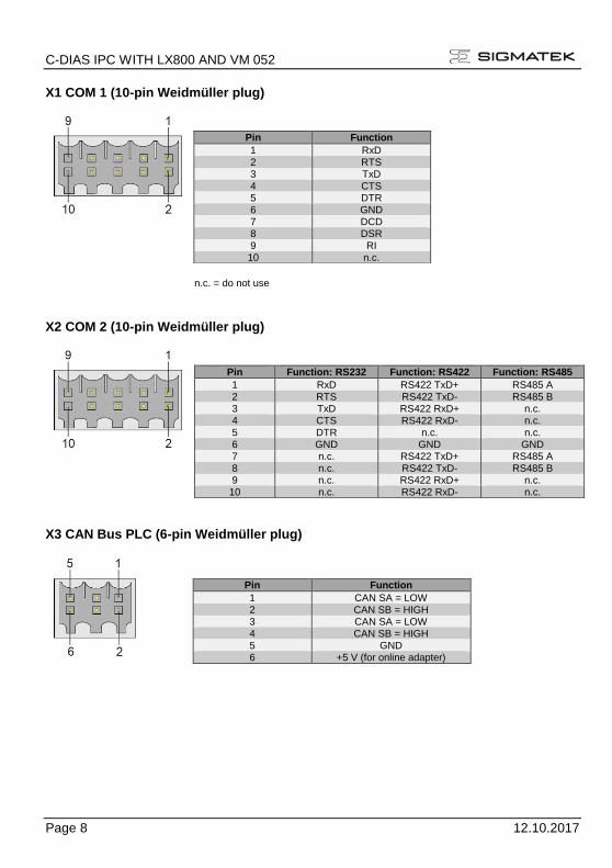
X1 COM 1 (10-pin Weidmüller plug)
n.c. = do not use
X2 COM 2 (10-pin Weidmüller plug)
X3 CAN Bus PLC (6-pin Weidmüller plug)
Pin Function
1 RxD 2 RTS 3 TxD 4 CTS 5 DTR 6 GND 7 DCD 8 DSR
9 RI 10 n.c.
Pin Function: RS232 Function: RS422 Function: RS485
1 RxD RS422 TxD+ RS485 A 2 RTS RS422 TxD- RS485 B
3 TxD RS422 RxD+ n.c. 4 CTS RS422 RxD- n.c. 5 DTR n.c. n.c. 6 GND GND GND 7 n.c. RS422 TxD+ RS485 A 8 n.c. RS422 TxD- RS485 B 9 n.c. RS422 RxD+ n.c. 10 n.c. RS422 RxD- n.c.
Pin Function
1 CAN SA = LOW 2 CAN SB = HIGH 3 CAN SA = LOW 4 CAN SB = HIGH 5 GND 6 +5 V (for online adapter)

C-DIAS IPC WITH LX800 AND VM 052
12.10.2017 Page 9
X4 CAN Bus Terminal (6-pin Weidmüller plug)
X5 DIAS Bus (6-pin Weidmüller plug)
X6 USB (Type A)
X7 S-DVI (26-pin HD-DSUB)
Pin Function
1 CAN A = LOW 2 CAN B = HIGH 3 CAN A = LOW 4 CAN B = HIGH 5 GND 6 n.c.
Pin Function
1 MBUS+ 2 MBUS- 3 SBUS+ 4 SBUS- 5 GND 6 n.c.
Pin Function
1 +5 V 2 D0- 3 D0+ 4 GND
Pin Function Pin Function
1 DVI1+ 14 Shielded 2 DVI1- 15 Shielded 3 DVI2+ 16 Shielded 4 DVI2- 17 Shielded 5 DVI3+ 18 Shielded 6 DVI3- 19 +24 V 7 DVIC+ 20 +24 V 8 DVIC- 21 USB Ext. In+ 9 Reserved 22 USB Ext. In-
10 GND 23 USB Ext. Out+ 11 GND 24 USB Ext. Out- 12 Shielded 25 CAN A 13 Shielded 26 CAN B
a

C-DIAS IPC WITH LX800 AND VM 052
Page 10 12.10.2017
X8 Ethernet 1 (8-pin RJ45)
8 1
Problems can arise if a control is connected to an IP network, which contains mod-
ules that do not contain a SIGMATEK operating system. With such devices, Ethernet
packets could be sent to the control with such a high frequency (i.e. broadcasts),
that the high interrupt load could cause a real-time runtime error or runtime error. By
configuring the packet filter (Firewall or Router) accordingly however, it is possible
to connect a network with SIGMATEK hardware to a third party network without trig-
gering the error mentioned above.
Des problèmes peuvent survenir si un automate est connecté à un réseau IP conte-
nant des modules qui ne fonctionnent pas sous un système d'exploitation SIGMA-
TEK. Avec de tels dispositifs, les paquets Ethernet peuvent être envoyés à
l’automate avec une fréquence tellement élevée (càd. diffusion), que les interrup-
tions ainsi générées peuvent provoquer une erreur d'exécution. En configurant
d’une façon appropriée le filtre de paquets (pare-feu ou un routeur) il est toutefois
possible de connecter un réseau avec le matériel SIGMATEK à un réseau tiers sans
déclencher l'erreur mentionnée ci-dessus.
X9 Video (RGB)
Pin Function
1 TD+ 2 TD– 3 RD+ 4 n.c. 5 n.c. 6 RD– 7 n.c. 8 n.c.
Pin Function
1 Red
2 GND
3 Green
4 GND
5 Blue
6 GND
7 Vsync
8 GND
9 Hsync
10 GND

C-DIAS IPC WITH LX800 AND VM 052
12.10.2017 Page 11
X10 Power Supply 18 - 30 Volts DC 2-pin Phoenix 3,5 mm (power supply)
X11 External UPS Connection 6-pin Phoenix 3,5 mm (UPS)
Applicable connectors
COM1/COM2: 10-pin Weidmüller plug B2L3, 5/10
CAN/ DIAS bus: 6-pin Weidmüller connector plug B2L3, 5/6
USB: Type A
Ethernet/VARAN: 8-pin RJ 45
Video: 10-pin RM 2.54
Power: 2-pin Phoenix FK-MCP 1.5/2-ST-3.5
USV: 6-pin Phoenix FK-MCP 1.5/6-ST-3.5
The complete C-DIAS CKL 012 connector set with spring terminals is available from SIG-MATEK under the article number 12-600-012.
S-DVI Cable 0.3 m 2 m 3 m 3.5 5 m 7 m 10 m 15 m
Art.Nr.: 05-950-003 Art.Nr.: 05-950-020 Art.Nr.: 05-950-030 Art.Nr.: 05-950-035 Art.Nr.: 05-950-050 Art.Nr.: 05-950-070 Art.Nr.: 05-950-100 Art.Nr.: 05-950-150
Pin Function
1 +24 V 2 GND
Pin Function
1 RxD 2 TxD 3 RTS (USV Off) 4 CTS (+24 V OK) 5 DCD (Battery weak) 6 GND
1
1

C-DIAS IPC WITH LX800 AND VM 052
Page 12 12.10.2017
NOTE:
Connecting the S-DVI cable under voltage can damage the S-DVI interface; it is not
hot-plug capable.
Bottom Connectors
X12 C-DIAS Bus Connector
16 1
c
b
a
X13 DIAS Bus Connector
1
14
Caution! To connect the DIAS module to X13 of the C-IPC, a DIAS power module (power booster)
between the C-IPC and DIAS module is required. The measure is necessary to protect the C-IPC from EMV-noise and to unburden the DCDC converter in the C-IPC (reducing power
loss in the C-IPC).
ATTENTION! Pour pouvoir brancher le module DIAS sur X13 du C-IPC, un module d’alimentation DIAS (puissance d'appoint) est nécessaire entre les modules C-IPC et DIAS. Il est également
nécessaire de protéger le C-IPC contre les perturbations électromagnétique et de soulager le convertisseur DCDC dans le C-IPC (réduisant les pertes de puissance dans le C-IPC).
Pin Function
1 GND
2 MBUS+
3 MBUS- 4 GND
5 SBUS+
6 SBUS- 7 GND
8 DCOK
9 - 13 +5 V
14 GND
b

C-DIAS IPC WITH LX800 AND VM 052
12.10.2017 Page 13
Connection to the C-IPC (X13)
Connection to the 1st DIAS-module
DPB 002 05-002-002l

C-DIAS IPC WITH LX800 AND VM 052
Page 14 12.10.2017
Expansion Card Connections

C-DIAS IPC WITH LX800 AND VM 052
12.10.2017 Page 15
X14/X15: VARAN-Out 1/2/3 (8-pin RJ45)
More information on the VARAN bus can be found in the VARAN bus specifications !
Pin Function
1 TX/RX+ 2 TX/RX- 3 RX/TX+ 4 Not used 5 Not used 6 RX/TX- 7 Not used
8 Not used
C-DIAS IPC WITH LX800 AND VM 052
Page 16 12.10.2017
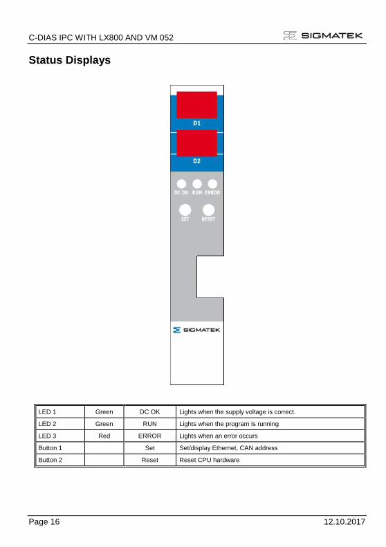
Status Displays
LED 1 Green DC OK Lights when the supply voltage is correct.
LED 2 Green RUN Lights when the program is running
LED 3 Red ERROR Lights when an error occurs
Button 1 Set Set/display Ethernet, CAN address
Button 2 Reset Reset CPU hardware

C-DIAS IPC WITH LX800 AND VM 052
12.10.2017 Page 17
LED 4 Yellow Active VARAN 1 Lights when data is exchanged over VARAN-Out 1
Green Link VARAN 1 Lights with a connection to VARAN-Out 1
LED 5 Yellow Active VARAN 2 Lights when data is exchanged over VARAN-Out 2
Green Link VARAN 2 Lights with a connection to VARAN-Out 2
LED 6 Yellow Active Ethernet 2 Lights when data is exchanged over Ethernet 2
Green Link Ethernet 2 Lights with a connection to Ethernet 2

C-DIAS IPC WITH LX800 AND VM 052
Page 18 12.10.2017
SIGMATEK Components
• 7-segment display for CPU status
• Reset button
• Set button
• DC OK LED
• Error LED
• Run LED
• Timer - 1 µs precision with Interrupt capability
• EEPROM for configuration and version management
• S-DVI interface including: - Keyboard - USB - Touch - Chip card - PC speakers - 18-Bit TFT, TMDS coded signal (3x data, 1x clk), max. resolution 1024x768

C-DIAS IPC WITH LX800 AND VM 052
12.10.2017 Page 19
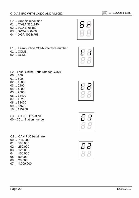
Setting C-IPC Parameters with the SET Button (with the LASAL operating system only) To enter the mode to change settings, press and hold the SET button while the C-IPC is booting When the following display appears
the SET button can be released. The upper section of the display shows which setting can be changed; the lower section of the display shows the set value. The blinking part of the display can be set with a short press of the SET button: If the upper section is blinking, the various settings can be viewed by quickly pressing the set button multiple times. To change between the setting and the value, the Set button must be pressed for about 1.5 s. Once the desired changes are made, press the SET button for about 5 seconds to end the process. If the changes are to be discarded, press the RESET button to restart the C-IPC The settings for the IP address, subnet mask and gateway are hexadecimal, whereas in the left and right digits, 0 - F must be entered separately. The changeover is triggered by pressing the SET button for about 1.5 s When changing the graphic resolution, a special feature is available: Because the BIOS must first read the new value, the computer must be restarted (Reset value, current supply) The values from AUTOEXEC.LSL are used as the standard settings; changes are written back to this file. Before this, the original content of the file is written to AUTOEXEC.BAK.
C-DIAS IPC WITH LX800 AND VM 052
Page 20 12.10.2017
Gr ... Graphic resolution 01 ... QVGA 320x240 02 ... VGA 640x480 03 ... SVGA 800x600 04 … XGA 1024x768 L1 … Lasal Online COMx interface number 01 ... COM1 02 ... COM2 L2 .. Lasal Online Baud rate for COMx 00 ... 300 01 ... 600 02 ... 1200 03 ... 2400 04 ... 4800 05 ... 9600 06 ... 14400 07 ... 19200 08 ... 38400 09 ... 57600 10 ... 115200 C1 ... CAN PLC station 00 – 30 ... Station number C2 ... CAN PLC baud rate 00 ... 615.000 01 … 500.000 02 … 250.000 03 … 125.000 04 … 100.000 05 … 50.000 06 … 20.000 07 … 1.000.000

C-DIAS IPC WITH LX800 AND VM 052
12.10.2017 Page 21
I1, I2, I3, I4 IP Address I1.I2.I3.I4, hexadecimal 00-FF each S1,S2,SI3,S4 Subnet Mask SI1SI2.S3.S4, hexadecimal 00-FF respectively G1,G2,G3,G4 Gateway G1,G2.G3.G4, hexadecimal 00-FF respectively
C-DIAS IPC WITH LX800 AND VM 052
Page 22 12.10.2017
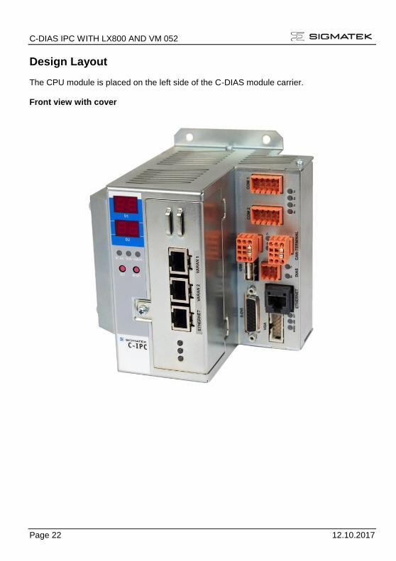
Design Layout The CPU module is placed on the left side of the C-DIAS module carrier.
Front view with cover

C-DIAS IPC WITH LX800 AND VM 052
12.10.2017 Page 23
Rear view with cover

C-DIAS IPC WITH LX800 AND VM 052
Page 24 12.10.2017
Front view without cover

C-DIAS IPC WITH LX800 AND VM 052
12.10.2017 Page 25
Exchanging the Compact Flash Card To exchange the Compact Flash card, remove the screws and carefully tilt the cover to the front as shown below.
Next, remove the old flash card and insert the new card as shown. Finally, replace the cover and tighten the screws.

C-DIAS IPC WITH LX800 AND VM 052
Page 26 12.10.2017
Exchanging the Battery The battery can only be exchanged when the C-IPC is OFF! To exchange the battery, remove the screws and carefully tilt the cover to the front as shown below.
Next, remove the old battery from the fixture and insert the new one. When inserting the new battery, ensure the polarity is correct. Finally, replace the cover and tighten the screws.

C-DIAS IPC WITH LX800 AND VM 052
12.10.2017 Page 27
CAN Bus Termination In a CAN bus system, both end modules must be terminated. This is necessary to avoid transmission errors caused by reflections in the line.
Module1 Module 2 Module 3 Module n
I.e. CPUDCP 160
I.e. TerminalET 081
CAN bus connection
DSUB plugwith terimatingresistors
I.e. TerminalET 805
If the C-IPC is an end module, it can be terminated by placing a 150-Ohm resistor between CAN-A (Low) and CAN-B (High).
1 x 150R Widerstand

C-DIAS IPC WITH LX800 AND VM 052
Page 28 12.10.2017
USB Interface Connections The C-IPC has a USB interface connection that can used in LASAL to connect various USB devices (keyboard, mouse, storage media, hubs …). Several USB devices, which are fully functional in LASAL, can be connected using a hub. The following restriction applies to the BIOS setup:
The BIOS setup can only be operated when the USB keyboard is connected directly
to the USB socket. Using a USB hub can cause errors in the BIOS setup!
La configuration du BIOS est accessible uniquement si le clavier est connecté direc-
tement à la prise USB. L'utilisation d'un concentrateur USB peut provoquer des er-
reurs dans la configuration du BIOS!
It should be noted that many of the USB devices on the market do not comply with USB specifications; this can lead to device malfunctions. It is also possible that these devices
will not be detected at the USB port or function correctly. Therefore, it is recommended that every USB stick be tested before actual use.
DIAS Bus Termination In a DIAS bus system, both end modules must be terminated. This is necessary to avoid transmission errors caused by reflections in the line.
The DIAS bus termination is integrated in the C-IPC and must no longer be built into
the DIAS bus connector.

C-DIAS IPC WITH LX800 AND VM 052
12.10.2017 Page 29
The DIAS Bus Connection To ensure a good bus connection, several wiring guidelines must be followed:
• The cable used must be designed for the data transfer speed: Data cables (10Mbit, 2 x 2 wire TWISTED PAIR, shielded) i.e.: LAPPKABEL / UNITRONIC-BUSLEITUNG FD P LD
• Because of the internal resistance of the module, the cable impedance should be 100 Ohms.
• With twisted-pair cables, ensure that the correct pairs are connected to one another: 2x2 pair cables: Pair 1 MBUS+ MBUS- Pair 2 SBUS+ SBUS-
• The shielding must be connected over a large area and the shortest possible route.
• To connect the individual wires to the connector, the insulation must be removed and the exposed shielding shifted to the side. Only remove as much of the insulation and shielding as needed.
• The send and receive modules must have the same GND potential.
The maximum length allowed for twisted-pair cables per DIAS bus connector is 20 M
(when using the UNITRONIC BUS cable FD P LD / Fa. LAPPKABEL)
La longueur maximale totale d'un câble à paire torsadée est de 20m (lors de l'utilisa-
tion UNITRONIC BUS FD P LD / Fa. LAPPKABEL).

C-DIAS IPC WITH LX800 AND VM 052
Page 30 12.10.2017
Example
The C-IPC can also be connected to a DIAS module. However, the DIAS modules require a power supply (a DPS 001, for example) as well as an adapter module for connect the twisted-pair cable to the ribbon cable connector (i.e.: DKO 012 /013).
z.B.: C-IPC
C-DIAS IPC WITH LX800 AND VM 052
12.10.2017 Page 31
Connecting DIAS Modules The C-IPC can also be connected to DIAS modules. Here, 2 options are available:
1. Connection over a DIC 121
The DIAS bus connection between the C-IPC and DIC 121 is a point-to-point connec-tion and must therefore be terminated on both sides. The DIC 121 has an integrated bus termination Wiring the C-IPC:
o X1: Install bus termination (2x 100 Ω) o X2: Connect to DIC 121
2. Connection over a DKO 011 or DKO 013:
If both DIAS bus connectors on the C-IPC are needed, a DKO 011 or DKO 013 can be used in combination with a DPS 001 power supply module. Wiring the DIAS modules with a DPS 001:
o Left: DPS 001 power supply module o Right: DKO 011 or DKO 013 adapter module
Wiring the C-IPC:
o X1: DIAS bus to CIC interface modules or bus termination (2 x 100 Ω) o X2: Connection to DKO 011 or DKO 013 adapter module

C-DIAS IPC WITH LX800 AND VM 052
Page 32 12.10.2017
Buffer Battery The exchangeable buffer battery ensures that programs and data in the user memory (RAM) are preserved in the absence of a supply voltage. A lithium battery is installed at the manufacturer. The battery has enough capacity to preserve data in the absence of a supply voltage for up to 3 years. We recommend however, that the battery be replaced annually to ensure optimal perfor-mance.
Battery order number: 01-690-028
MANUFACTURER TYPE DATA
Lithium battery RENATA CR2032 3 V
Replace battery with RENATA Part No. CR2032 only. Use of other battery may
present a risk of fire or explosion. See owner's manual for safety instructions.
N'utilisez que des piles RENATA CR2032! Avec d'autres piles, un risque d'incendie
ou d'explosion existe!
Caution: The battery can only be changed when the C-IPC is off! After the +24 V supply is removed,
the battery is buffered for approximately 15 minutes (via ELKO). The battery must be changed within this period or data loss occurs.
Attention: La pile ne doit être changée que si le C-IPC est éteint! Après avoir débranché l'alimenta-
tion +24 V, la pile est tamponnée pendant 15 minutes (via ELKO). La pile doit être rempla-cée pendant ce laps de temps sinon les données seront perdues.

C-DIAS IPC WITH LX800 AND VM 052
12.10.2017 Page 33
Storage Media
It is recommended that only storage media provided by SIGMATEK
(CompactFlash cards, microSD cards etc.) be used.
The number of read and write actions have a significant influence on the
lifespan of the storage media.
Il est recommandé d’utiliser uniquement les supports de stockage fournis par
SIGMATEK (Cartes CompactFlash, cartes microSD, etc).
Le nombre de lectures et d'écritures ont un effet significatif sur la durée de vie du
support de stockage.
Cooling The terminal's power loss can reach up to 50 Watts. The built-in fan removes most of the generated heat. Also when mounted, heat dissipation must be ensured.
At processor temperatures above the allowed limit, the C-IPC will shut down auto-
matically! The C-IPC will only resume normal operation after a sufficient cooling period (1 minute). After an emergency shutdown, the fan function and environmental conditions should be
checked.
Le S-IPC s'arrête automatiquement en présence d’une température trop élevée du
processeur! Le C-IPC revient au fonctionnement normal après une phase de refroidissement suffisante (1 minute). Après un arrêt d'urgence, le fonctionnement correct du ventilateur ainsi que les
conditions d'environnement doivent être vérifiés.

C-DIAS IPC WITH LX800 AND VM 052
Page 34 12.10.2017
System Boot Checkpoints
The checkpoints are shown on the 7-segment display before the LASAL CLASS software status and error messages. Since this involves checkpoints, it should be interpreted as errors when the system stops at a checkpoint.
Number Meaning Cause/solution
1F The operating system or application cannot be started
- Check operating system/boot medium
- Boot medium not inserted
- Boot medium defective
- No operating system on the boot medium
A5, BF Error in RAM - The module detected an error in the RAM during the
self-test.

C-DIAS IPC WITH LX800 AND VM 052
12.10.2017 Page 35
Status and Error Messages Status and error messages are shown in the status test of the LASAL CLASS software. If the CPU has a status display, the status or error number is also show here as well. POINTER or CHKSUM messages can also be shown on the terminal screen.
Number Message Definition Cause/solution
00 RUN RAM The user program is currently running in RAM.
The display is not affected.
01 RUN ROM The user program stored in the program memory module has been loaded into the RAM is currently running.
The display is not affected.
02 RUNTIME The total time for all cyclic objects exceed the maximum time; the time can be configured using two system variables:
-Runtime: time remaining
-SWRuntime: pre-selected value for the runtime counter
03 POINTER Incorrect program pointers were detected before running the user program
Possible Causes:
- The program memory module is missing, not programmed or defect.
- The program in the user program memory (RAM) is not executable.
- The buffering battery has failed.
- The user program is overwriting a software error
Solution:
- Reprogram the memory module, if the error reoccurs exchange the module.
- Exchange the buffering battery
- Correct programming error
04 CHKSUM An invalid checksum was detected before running the user program.
Cause/solution: s. POINTER

C-DIAS IPC WITH LX800 AND VM 052
Page 36 12.10.2017
05 WATCHDOG The program was interrupted through the watchdog logic.
Possible Causes:
- Interrupts blocked by the user program for an extensive period of time (STI instruction forgotten).
- Programming error in a hardware interrupt.
- INB, OUTB, INW, OUTW instruc-tions used incorrectly.
- The processor is defect.
Solution:
- Correct programming error.
- Exchange CPU.
06 GENERAL
ERROR General error
07 PROM DE-
FECT An error has occurred while programming the memory module.
Cause:
- The program memory module is defect.
- The user program is too large.
- The program memory module is
missing.
Solution:
- Exchange the program memory module
08 RESET The CPU has received the reset signal and is waiting for further instructions.
The user program is not processed.
09 WD DEFEKT The hardware monitoring circuit (watch-dog logic) is defect.
After power-up, the CPU checks the watchdog logic function. If an error occurs during this test, the CPU deliber-ately enters an infinite loop from which no further instructions are accepted.
Solution: Exchange CPU.
10 STOP
11 PROG BUSYS
12 PROGRAM
LENGTH
13 PROG END The memory module was successfully completed.
14 PROG MEMO The CPU is currently programming the memory module.
C-DIAS IPC WITH LX800 AND VM 052
12.10.2017 Page 37
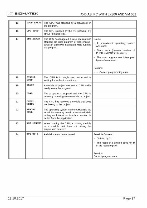
15 STOP BRKPT The CPU was stopped by a breakpoint in the program.
16 CPU STOP The CPU stopped by the PG software (F6 HALT in status test).
17 INT ERROR The CPU has triggered a false interrupt and stopped the user program or has encoun-tered an unknown instruction while running the program.
Cause:
- A nonexistent operating system was used.
- Stack error (uneven number of PUSH and POP instructions).
- The user program was interrupted by a software error.
Solution:
- - Correct programming error.
18 SINGLE
STEP The CPU is in single step mode and is waiting for further instructions.
19 READY A module or project was sent to CPU and is ready to run the program
20 LOAD The program is stopped and the CPU is
currently receiving a new module or project.
21 UNZUL.
MODUL The CPU has received a module that does not belong to the project.
22 MEMORY
FULL The operating system memory /Heap) is too small. No memory could be reserved while calling an internal or interface function is called from the application.
23 NOT LINKED When starting the CPU, a missing module or a module that does not belong the project was detected.
24 DIV BY 0 A division error has occurred. Possible Causes:
- Division by 0.
- The result of a division does not fit in the result register.
Solution: Correct program error

C-DIAS IPC WITH LX800 AND VM 052
Page 38 12.10.2017
25 DIAS ERROR While accessing a DIAS module, an error has occurred.
Possible Causes:
- An attempt is made to access a nonexistent DIAS module.
- DIAS bus error.
Solution:
- Check the DIAS bus
- Check the termination resis-tors.
26 WAIT The CPU is busy.
27 OP PROG The operating system is currently being reprogrammed.
28 OP INSTALLED The operating system has been reinstalled.
29 OS TOO LONG The operating system cannot be loaded; too little memory.
30 NO OPERATING SYSTEM Boot loader message.
No operating system found in
RAM.
31 SEARCH FOR OS The boot loader is searching for the operating system in RAM.
32 NO DEVICE
33 UNUSED CODE
34 MEM ERROR The operating system loaded does not match the hardware configura-tion.
35 MAX IO
36 MODULE LOAD ERROR The LASAL Module or project cannot be loaded.
37 GENERELLER BS-FEHLER A general error has occurred while loading the operating system.
38 APPLMEM ERROR An error has occurred in the application memory (user heap).
39 OFFLINE
40 APPL LOAD
41 APPL SAVE

C-DIAS IPC WITH LX800 AND VM 052
12.10.2017 Page 39
44 VARAN MANAGER ERROR In the VARAN Manager, an error number was stored and the pro-gram execution was stopped.
Possible causes:
- Real network does not match the project
Solution:
- Read log file
45 VARAN ERROR A required VARAN Client was removed or a communication error has occurred. The program execu-tion has stopped.
Possible causes:
- Damaged wiring
- Missing energy supply for
decentralized modules
Solution:
- Read Log file
- Analyze error tree
46 APPL-LOAD-ERROR An error has occurred while loading the application.
47 APPL-SAVE-ERROR An error has occurred while attempting to save the application.
50 ACCESS-EXCEPTION-
ERROR A read or write access of a re-
stricted memory area. (I.e. writing to the NULL pointer).
51 BOUND EXCEEDED An exception error caused by exceeding the memory limits
52 PRIVILEDGED INSTRUC-
TION An unauthorized instruction for the current CPU level was given. For example, setting the segment register.
53 FLOATING POINT ERROR An error has occurred during a floating-point operation.
60 DIAS-RISC-ERROR Error from the Intelligent DIAS-
Master.
64 INTERNAL ERROR An internal error has occurred, all applications are stopped.
Restart; report error to Sigmatek.
65 FILE ERROR An error has occurred during a file operation.
66 DEBUG ASSERTION
FAILED Internal error. Restart; report error to Sigmatek.
67 REALTIME RUNTIME The total time for all real time objects exceeds the maximum time allowed. The time cannot be
configured.
2 ms for 386 CPUs
1 ms for all other CPUs
Starting from Version 1.1.7

C-DIAS IPC WITH LX800 AND VM 052
Page 40 12.10.2017
68 BACKGROUND RUNTIME The total time for all background objects exceed the maximum time; the time can be configured using two system variables:
-BTRuntime: time remaining
-SWBTRuntime: pre-selected value for the runtime counter
70 C-DIAS ERROR An error occurred in connection with a C-DIAS module.
Cause:
- The reason for this error is documented in the log file
Solution:
- Depends on the cause
72 S-DIAS ERROR A connection error with a S-DIAS module has occurred.
Possible causes:
- real network does not match the project
- S-DIAS client is defective
Solution:
- analyze logfile
73 EEPROM
ERROR An error has occurred while reading
the CPU EEPROM.
Cause:
- Accessing I²C has failed multiple times due to a hardware defect.
Solution:
- Restart the CPU - After repeated failure, exchange CPU
75 SRAM ERROR An error occurred while initializing, reading or writing SRam data.
Possible Causes:
- SRam configured incorrectly
- Battery fort he internal pro-gram memory supply is empty
Solution:
- Analyze log file (Event00.log, Event19.log)
- Check configuration
- Change internal program memory supply battery
95 USER DEFINED 0 User-definable code.
96 USER DEFINED 1 User-definable code.
97 USER DEFINED 2 User-definable code.
98 USER DEFINED 3 User-definable code.
99 USER DEFINED 4 User-definable code.

C-DIAS IPC WITH LX800 AND VM 052
12.10.2017 Page 41
100 C_INIT Initialization start; the configuration is run.
101 C_RUNRAM The LASAL project was successfully started from RAM.
102 C_RUNROM The LASAL project was successfully started from ROM.
103 C_RUNTIME
104 C_READY The CPU is ready for operation.
105 C_OK The CPU is ready for operation.
106 C_UNKNOWN_CID An unknown object from a stand-alone or embedded object, or an unknown base class was detected.
107 C_UNKNOWN_CONSTR The operating system class cannot be created; the operating system is probably wrong.
108 C_UNKNOWN_OBJECT Indicates an unknown object in an interpreter program; more the one
DCC080 object.
109 C_UNKNOWN_CHNL The hardware module number is greater than 60.
110 C_WRONG_CONNECT No connection to the required chan-nels.
111 C_WRONG_ATTR Wrong server attribute.
112 C_SYNTAX_ERROR Non-specific error. Recompile and download all project sections.
113 C_NO_FILE_OPEN An attempt was made to open an
unknown table.
114 C_OUTOF_NEAR Memory allocation error
115 C_OUT OF_FAR Memory allocation error
116 C_INCOMAPTIBLE An object with the same name already exists but has a different class.
117 C_COMPATIBLE An object with the same name and class already exists but must be updated.
224 LINKING The application is currently linking.
225 LINKING ERROR An error has occurred while linking. An error messaged is generated in the LASAL status window.

C-DIAS IPC WITH LX800 AND VM 052
Page 42 12.10.2017
226 LINKING DONE Linking is complete.
230 OP BURN The operating system is currently being burned into the Flash memory.
231 OP BURN FAIL An error has occurred while burning the operating system.
232 OP INSTALL The operating system is currently being installed.
240 USV-WAIT The power supply was disconnected;
the UPS is active.
241 REBOOT The operating system is restarted.
242 LSL SAVE
243 LSL LOAD
252 CONTINUE
253 PRERUN The application is started.
254 PRERESET The application is ended.
255 CONNECTION BREAK

C-DIAS IPC WITH LX800 AND VM 052
12.10.2017 Page 43
Recommended Shielding for VARAN The real-time VARAN Ethernet bus system exhibits very robust characteristics in industrial environments. Through the use of IEEE 802.3 standard Ethernet physics, the potentials between an Ethernet line and sending/receiving components are separated. Messages to a bus participant are immediately repeated by the VARAN Manager in the event of an error. The shielding described below is principally recommended. For applications in which the bus is run outside the control cabinet, the correct shielding is required. Especially when for structural reasons, the bus line must be placed next to strong electromagnetic interference. It is recommended to avoid placing Varan bus lines parallel to power cables whenever possible. SIGMATEK recommends the use of CAT5e industrial Ethernet bus cables. For the shielding, an S-FTP cable should be used. An S-FTP bus is a symmetric, multi-wire cable with unshielded pairs. For the total shield-ing, a combination of foil and braiding is used. A non-laminated variant is recommended.
The VARAN cable must be secured at a distance of 20 cm from the connector for
protection against vibration!
C-DIAS IPC WITH LX800 AND VM 052
Page 44 12.10.2017
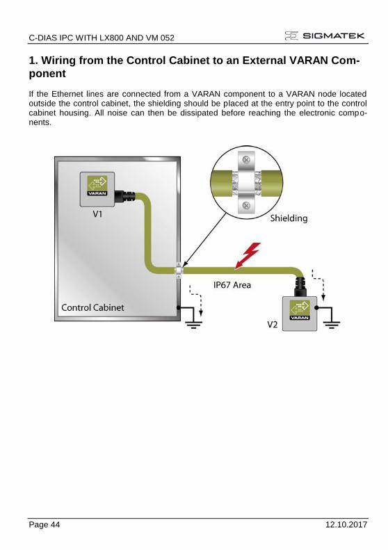
1. Wiring from the Control Cabinet to an External VARAN Com-
ponent If the Ethernet lines are connected from a VARAN component to a VARAN node located outside the control cabinet, the shielding should be placed at the entry point to the control cabinet housing. All noise can then be dissipated before reaching the electronic compo-nents.
C-DIAS IPC WITH LX800 AND VM 052
12.10.2017 Page 45
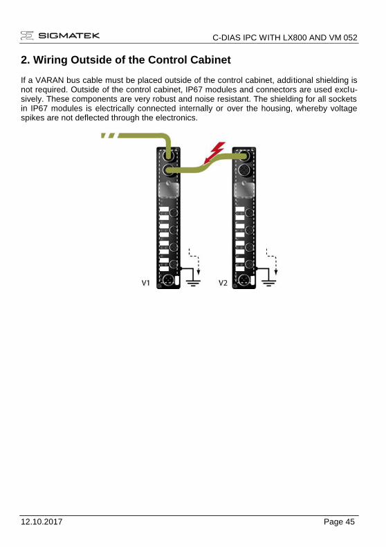
2. Wiring Outside of the Control Cabinet If a VARAN bus cable must be placed outside of the control cabinet, additional shielding is not required. Outside of the control cabinet, IP67 modules and connectors are used exclu-sively. These components are very robust and noise resistant. The shielding for all sockets in IP67 modules is electrically connected internally or over the housing, whereby voltage spikes are not deflected through the electronics.
C-DIAS IPC WITH LX800 AND VM 052
Page 46 12.10.2017
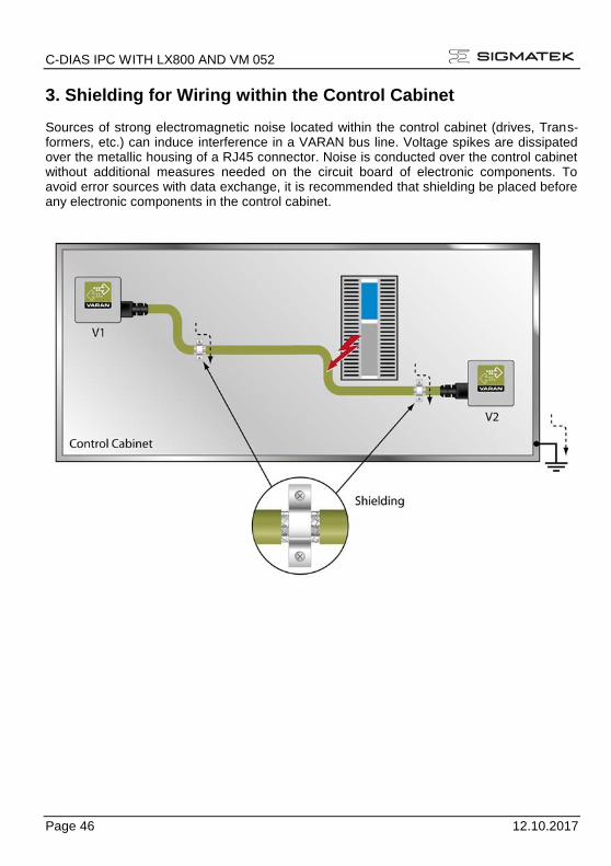
3. Shielding for Wiring within the Control Cabinet Sources of strong electromagnetic noise located within the control cabinet (drives, Trans-formers, etc.) can induce interference in a VARAN bus line. Voltage spikes are dissipated over the metallic housing of a RJ45 connector. Noise is conducted over the control cabinet without additional measures needed on the circuit board of electronic components. To avoid error sources with data exchange, it is recommended that shielding be placed before any electronic components in the control cabinet.

C-DIAS IPC WITH LX800 AND VM 052
12.10.2017 Page 47
4. Connecting Noise-Generating Components. When connecting power lines to the bus that generate strong electromagnetic noise, the correct shielding is also important. The shielding should be placed before a power element (or group of power elements).

C-DIAS IPC WITH LX800 AND VM 052
Page 48 12.10.2017
5. Shielding Between Two Control Cabinets If two control cabinets must be connected over a VARAN bus, it is recommended that the shielding be located at the entry points of each cabinet. Noise is therefore prevented from reaching the electronic components in both cabinets.