c. lu, rpc system installation workshop, 6/11/2009, cuhk 1 1 rpc gas system installation (step by...
Post on 21-Dec-2015
220 views
TRANSCRIPT
C. Lu, RPC System Installation Workshop, 6/11/2009, CUHK 1 1
RPC gas system installation(step by step plan)
(CUHK, 6/11/2009)
Changguo Lu, Kirk McDonald
Princeton University
C. Lu, RPC System Installation Workshop, 6/11/2009, CUHK 2 2
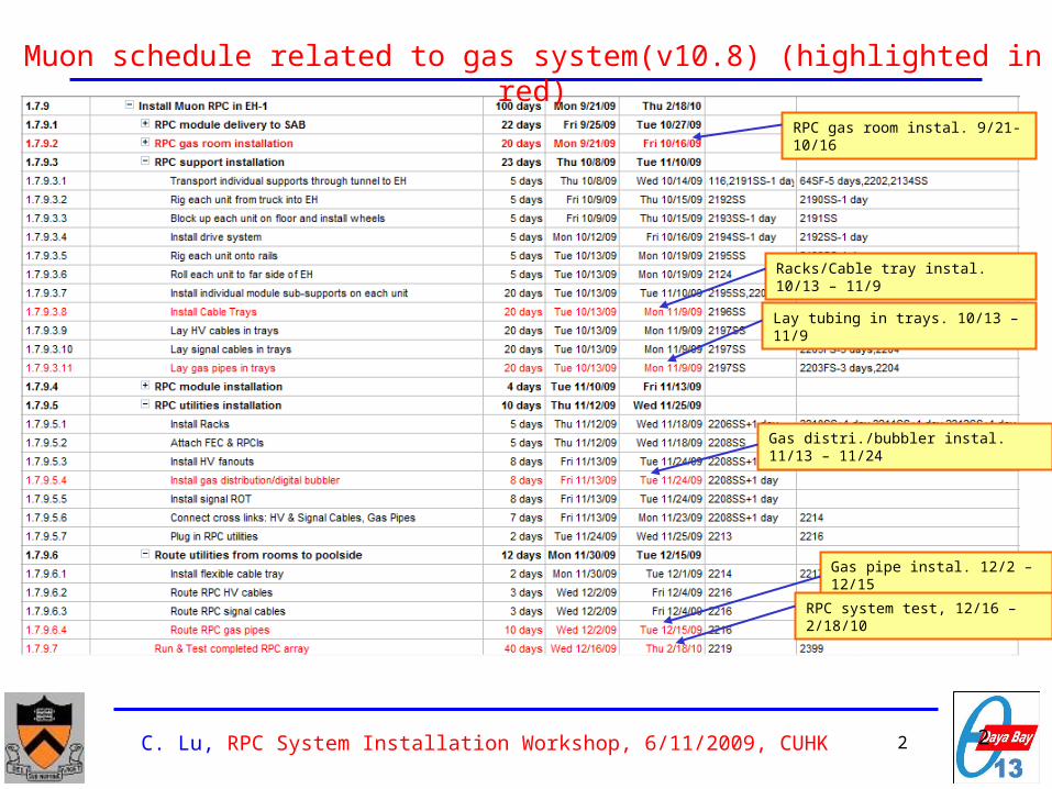
RPC gas room instal. 9/21-10/16
Racks/Cable tray instal. 10/13 – 11/9
Gas distri./bubbler instal. 11/13 – 11/24
Lay tubing in trays. 10/13 – 11/9
Gas pipe instal. 12/2 – 12/15
RPC system test, 12/16 – 2/18/10
Muon schedule related to gas system(v10.8) (highlighted in red)
C. Lu, RPC System Installation Workshop, 6/11/2009, CUHK 3 3
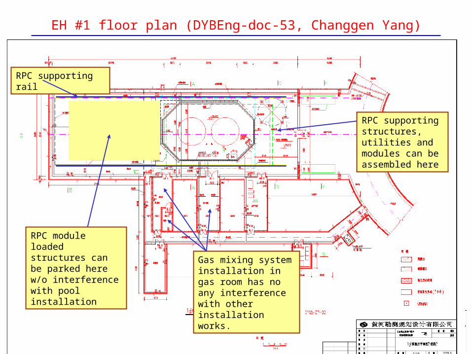
EH #1 floor plan (DYBEng-doc-53, Changgen Yang)
RPC supporting rail
RPC module loaded structures can be parked here w/o interference with pool installation
RPC supporting structures, utilities and modules can be assembled here
Gas mixing system installation in gas room has no any interference with other installation works.

C. Lu, RPC System Installation Workshop, 6/11/2009, CUHK 4 4
Step 1: Lay down gas tubing into cable tray.
Location: EH#1, Entrance area, where the supporting structure being assembled.
Supervisor: Princeton.
Installation team: Local.
Task: Cut the tube to right length; cap and stick labels to two ends; lay down the tube into the right cable tray and tie a bundle together.
Work load: 216 tubes into 9 cable trays.

Layout of gas tubingNote for calculation of RPC system cable/tube length, 5/2009, Guan Mengyun, IHEP

C. Lu, RPC System Installation Workshop, 6/11/2009, CUHK 6 6
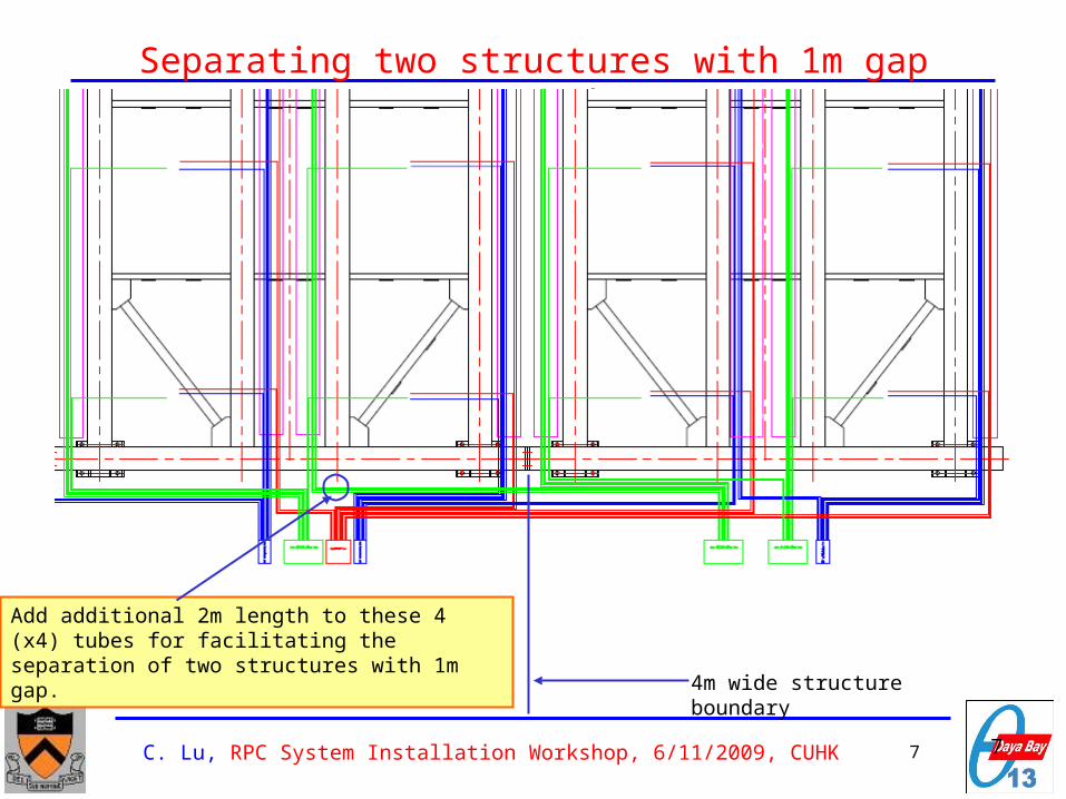
Separating two structures with 1m gap
4m wide structure boundary
Add 2m additional length to these 4 (x4) tubes for facilitating the separation of two structures with 1m gap.
C. Lu, RPC System Installation Workshop, 6/11/2009, CUHK 7 7
Separating two structures with 1m gap (cont’d)
4m wide structure boundary
Add additional 2m length to these 4 (x4) tubes for facilitating the separation of two structures with 1m gap.

C. Lu, RPC System Installation Workshop, 6/11/2009, CUHK 8 8
Individual tube length (m)
Tubing lengthColum
nRow1 Row2 Row3 Row4 Row5 Row6
1 5.48 7.48 9.48 11.48 13.48 15.48
2 6.39 8.39 10.39 12.39 14.39 16.39
3 4.48 6.48 14.48 16.48 18.48 20.48
4 6.79 8.79 10.39 12.39 14.39 16.39
5 4.88 6.88 8.88 10.88 12.88 14.88
6 6.39 8.39 10.39 12.39 14.39 16.39
7 4.48 6.48 14.48 16.48 18.48 20.48
8 6.79 8.79 10.39 12.39 14.39 16.39
9 4.88 6.88 8.88 10.88 12.88 14.88
total inlet/outlet618.1
6
total(2 inlet/outlet)2472.
6

C. Lu, RPC System Installation Workshop, 6/11/2009, CUHK 9 9
Individual tube labelInlet tubing label Column Row1 Row2 Row3 Row4 Row5 Row6
Branch 1 1H1C1R1B1I
nH1C1R2B1I
nH1C1R3B1I
nH1C1R4B1I
nH1C1R5B1I
nH1C1R6B1I
n
2H1C2R1B1I
nH1C2R2B1I
nH1C2R3B1I
nH1C2R4B1I
nH1C2R5B1I
nH1C2R6B1I
n
3H1C3R1B1I
nH1C3R2B1I
nH1C3R3B1I
nH1C3R4B1I
nH1C3R5B1I
nH1C3R6B1I
n
4H1C4R1B1I
nH1C4R2B1I
nH1C4R3B1I
nH1C4R4B1I
nH1C4R5B1I
nH1C4R6B1I
n
5H1C5R1B1I
nH1C5R2B1I
nH1C5R3B1I
nH1C5R4B1I
nH1C5R5B1I
nH1C5R6B1I
n
6H1C6R1B1I
nH1C6R2B1I
nH1C6R3B1I
nH1C6R4B1I
nH1C6R5B1I
nH1C6R6B1I
n
7H1C7R1B1I
nH1C7R2B1I
nH1C7R3B1I
nH1C7R4B1I
nH1C7R5B1I
nH1C7R6B1I
n
8H1C8R1B1I
nH1C8R2B1I
nH1C8R3B1I
nH1C8R4B1I
nH1C8R5B1I
nH1C8R6B1I
n
9H1C9R1B1I
nH1C9R2B1I
nH1C9R3B1I
nH1C9R4B1I
nH1C9R5B1I
nH1C9R6B1I
n
Column Row1 Row2 Row3 Row4 Row5 Row6
Branch 2 1H1C1R1B2I
nH1C1R2B2I
nH1C1R3B2I
nH1C1R4B2I
nH1C1R5B2I
nH1C1R6B2I
n
2H1C2R1B2I
nH1C2R2B2I
nH1C2R3B2I
nH1C2R4B2I
nH1C2R5B2I
nH1C2R6B2I
n
3H1C3R1B2I
nH1C3R2B2I
nH1C3R3B2I
nH1C3R4B2I
nH1C3R5B2I
nH1C3R6B2I
n
4H1C4R1B2I
nH1C4R2B2I
nH1C4R3B2I
nH1C4R4B2I
nH1C4R5B2I
nH1C4R6B2I
n
5H1C5R1B2I
nH1C5R2B2I
nH1C5R3B2I
nH1C5R4B2I
nH1C5R5B2I
nH1C5R6B2I
n
6H1C6R1B2I
nH1C6R2B2I
nH1C6R3B2I
nH1C6R4B2I
nH1C6R5B2I
nH1C6R6B2I
n
7H1C7R1B2I
nH1C7R2B2I
nH1C7R3B2I
nH1C7R4B2I
nH1C7R5B2I
nH1C7R6B2I
n
8H1C8R1B2I
nH1C8R2B2I
nH1C8R3B2I
nH1C8R4B2I
nH1C8R5B2I
nH1C8R6B2I
n
9H1C9R1B2I
nH1C9R2B2I
nH1C9R3B2I
nH1C9R4B2I
nH1C9R5B2I
nH1C9R6B2I
n
C. Lu, RPC System Installation Workshop, 6/11/2009, CUHK 10 10
Question #1
The prototype gas system at IHEP has used 6mm OD tubing while the fitting used in this gas system is ¼” OD polyflo fitting.
Can we decide the tube size for the gas system at EH#1 (and near future #2 and #3) is 6mm OD, and ordered in China? Can IHEP provide the local company’s name?
C. Lu, RPC System Installation Workshop, 6/11/2009, CUHK 11 11
Step 2: Install gas mixing system in gas room.
Location: Gas room.
Supervisor: Princeton.
Installation team: Princeton and local.
Task: Install the gas control crates and mixing panel onto racks, install gas cabinet, connect gas cylinders and exhaust duct, install GC system and connect to gas mixture, install 1 PC in gas room, test entire mixing system.
Work load: 1 mixing panel, 4 crates, 1 gas cabinet, 1 auto switchover, 3 manual switchover panels, 2 6-pack Ar, 2 isobutane, 2 SF6, 2 R134A cylinders, 1 exhaust duct.

C. Lu, RPC System Installation Workshop, 6/11/2009, CUHK 12 12
Step 3: Install gas distribution/digital bubbler crates onto racks.
Location: EH#1 (Entrance area?) and gas mixing room.
Supervisor: Princeton.
Installation team: Princeton, local.
Task: Mount the distribution/digital bubbler readout crates onto racks, filling oil into bubblers, connect gas tubes into correct channels (both inlet and outlet), connect flat cable, USB extenders, Ethernet cable, USB-RS232 cables, install 1 PCs in electronics room. Test the entire system with Ar gas.
Work load: 7 gas distribution/digital bubbler crates, 108 gas inlet/108 gas outlet tubes connection, 1 PC, 1 Ethernet cable, 7 flat cables, 7 USB-RS232 converters.

C. Lu, RPC System Installation Workshop, 6/11/2009, CUHK 13 13
Question #2
The PC installed in gas mixing room will have one Ethernet cable that needs to be connected to the digital bubbler readout crate at EH#1.
Can we use the same hole for the gas pipe on the wall to install this cable?
C. Lu, RPC System Installation Workshop, 6/11/2009, CUHK 14 14
Step 4: Install copper tubing from gas room to EH#1 :
Location: EH#1 and gas room.
Supervisor: Princeton.
Installation team: Local.
Task: Route ¾” copper tubing from gas room to EH #1 to reach the flexible gas hose. Install 12.3m long braided PTFE hose into flexible cable tray (see next slide).
Work load: Layout the route, cut copper tubing to right length, connect the copper tubes piece by piece, install the fixture at both ends.

C. Lu, RPC System Installation Workshop, 6/11/2009, CUHK 15 15
Flexible cable tray to avoid disconnecting the cables
The configuration of the flexible cable tray is shown in the above plot,
One end of the flexible cable tray is fixed at the trench , the other end is fixed at the center of RPC support structure, (details in next slides)
Given R=0.2m, offset=1m, we need 12.3m flexible cable tray for each site,
The RPC’s will move as a single unit except for repairing.
Far site pool
Total Length = 9.65m + π*R+ 2*offset
R is the bending radius,
Offset gives convenience to installation
(DocDB #2370, Guan Mengyun, Yang Changgen)

C. Lu, RPC System Installation Workshop, 6/11/2009, CUHK 16 16
Question #3
Can we decide the length of the flexible gas hose now? 12.3m?
Can we hire local skilled technician for installing the polyflo tubing, gas pipe, gas cylinders clamping fixtures, gas switchover panels? How to share the labor cost?

C. Lu, RPC System Installation Workshop, 6/11/2009, CUHK 17 17
Step 5: Test entire system with RPC modules.
Location: EH#1, gas mixing room.
Supervisor: Princeton.
Installation team: Princeton, local.
Task: Install GC system, check the gas mixing ratio through GC; check the bubbling rate for each sub-branch, stability of the system, interlock system functioning.

Summary of the installation steps