c520u_c531u_elect_repair_manual -...
TRANSCRIPT

C520U/C531U Repair Manual

Table of Contents
1-1-1. Display Picture – C520/C531 1-2-1. Component Placement - C520U/C531U Display 1-2-2. Component Placement - C520U/C531U Lower Body 1-3-1. Block Diagram - C520U/C531U Electronics 1-4-1. Wire Connections - C520U/C531U Display 1-4-2. Wire Connections - C520U/C531U Drive Board 1-5-1. LED Indicators - C520U / C531U Display Board 1-5-2. LED Indicators - C520U/C531U Drive Board 1-6-1. C520U/C531U Display Specifications 2-1-1. Display Malfunction Troubleshooting Table - C520U/C531U 2-1-2. Display Malfunction Troubleshooting Table - C520U/C531U, Continued. 3-1-1. Malfunction: Unit will not start (alternator). 3-2-1. Malfunction: Unit will not start (battery). 3-3-1. Malfunction: No RPM value 3-4-1. Malfunction: No resistance 3-5-1. Malfunction: Resistance is heavy. 3-6-1. Malfunction: Telemetry heart rate malfunction. 3-7-1. Malfunction: HTR heart rate malfunction 4-1-1. Mechanical Maintenance Schedule - C531U/C520U 4-2-1. Mechanical Troubleshooting Chart - C520U/C531U.

1-1. Display Picture - C520U/C531U
1-1-1

1-2. Component Placement - C520U/C531U Display
1-2-1
HR telemetry receiver board
HTR board
Display board

1-2. Component Placement - C520U/C531U Lower Body
1-2-2
Electro-magnet
Drive board
Flywheel with built-in alternator
Battery
Reed switch

1-3. Block Diagram - C520U/C531U Electronics
1-3-1
Display Board
Drive Board
Electro-magnet
Reed switch Battery
HTR board HR receiver
board
Sensor – L
Sensor – R
Alternator
Battery charger

1-4. Wire Connections - C520U/C531U Display
1-4-1
To HTR contact plates (left and right)
LED1 �Display power
supply
To drive board
To HTR board
To HR receiver
To display

1-4. Wire Connections - C520U/C531U Drive Board
1-4-2
To display board
To battery charger
To reed switch To battery
To electro-magnet To alternator
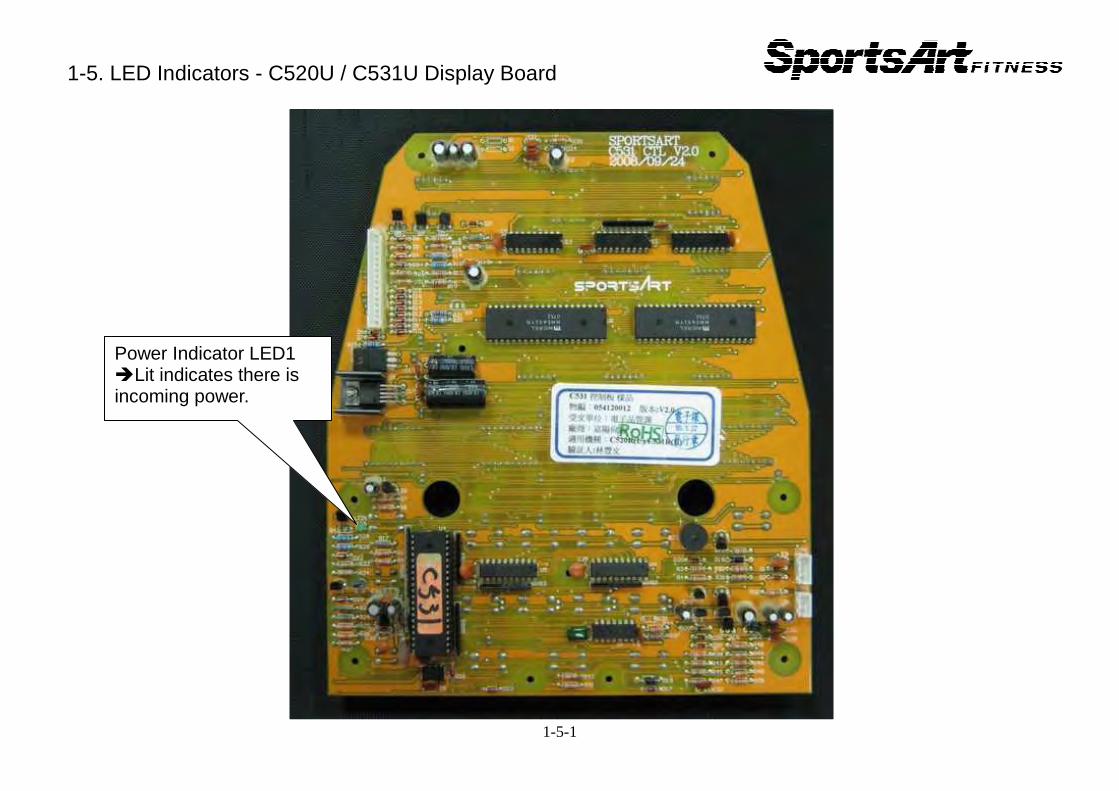
1-5. LED Indicators - C520U / C531U Display Board
1-5-1
Power Indicator LED1 �Lit indicates there is incoming power.

1-5. LED Indicators - C520U/C531U Drive Board
1-5-2
Alternator fuse F1
Battery fuse F2
CLK Indicator �LED flashes when pedals move.
Drive board power �Lit indicates there is incoming power.
Battery charge �Lit indicates there is incoming power to recharge the battery.
Exterior battery charger fuse F3

1-6. C520U/C531U Display Specifications
Specification Contents Notes Power supply AC alternator
Backup power supply
6.4 VA battery Battery automatically recharges or can be recharged via an exterior
charger.
Resistance Electro-magnet Speed detection Reed switch Resistance LEVEL 1 - LEVEL 20 Display method Segment array and numerical LEDs Main window Dot matrix
Character window
65% HR TARGET, Heart rate, 80% HR TARGET WORKOUT LEVEL / CALORIES / TIME / RPM DISTANCE / CAL/HR / WATTS / SPEED
Workout programs
INTERVAL / RANDOM / HILL / TRACK / ZONE TRAINER / CARDIO / WT LOSS
Heart rate control programs
CARDIO, WT LOSS, ZONE TRAINER
Heart rate Telemetry heart rate detection User IDs Four user IDs(USER1- USER4) Motion Belt operated
1-6-1

2-1. Display Malfunction Troubleshooting Table - C520U/C531U Malfunction Circumstance Inspection and Test Points Suggested
Components Notes
Cannot start unit
The display is not lit; I pedal the bike; but the display still doesn’t light.
1. Inspect cable connections. 2. Inspect drive board fuse. 3. Inspect drive board power LED. 4. Inspect the alternator.
1. drive board fuse
2. drive board 3. alternator
Cannot start unit
When I don’t pedal the bike, the display does not light.
1. Inspect battery fuse on the drive board. 2. Measure battery voltage. Battery voltage should be 5.5V
or more. 3. If battery voltage is under 5.5V, pedal the unit at over 50
RPM to recharge the battery. 4. Replace the battery if voltage is under 2.0 and it won’t
recharge.
1. battery fuse on the drive board
2. battery
Display won’t operate
I start pedaling the bike, but the display shows no reaction, and values don’t change.
RPM signal didn’t enter the display IC. Inspect RPM signal. 1. Inspect cable connections and the bridge board. 2. Inspect the reed switch and magnet. 3. Inspect the drive board CLK LED. 4. Inspect the reed switch and its wire.
1. magnet 2. reed switch
No resistance
I pedal the bike and press resistance keys. Resistance values on the display change. But there is no resistance.
1. Inspect cable connections. 2. Inspect alternator startup. If alternator will not start unit,
there will be no resistance. 3. Inspect the electro-magnet and its wires. 4. Test whether the drive board emits voltage to the electro-magnet.
1. drive board
2-1-1

Telemetry heart rate detection malfunction
Telemetry heart rate malfunction
1. Inspect heart rate transmitter and its batteries. Replace batteries if batteries haven’t been replaced for a long time. 2. Inspect heart rate receiver board cable connections. 3. Test or replace the heart rate receiver board. 4. Inspect environment for sources of interference, such as speakers and lights.
2. telemetry heart rate transmitter
3. telemetry heart rate receiver board
Contact heart rate malfunction
Contact heart rate malfunction
1. Inspect bridge board HTR cable. 2. Inspect HTR indicator LED on the drive board. 3. Replace the HTR board.
1. HTR board C531U
Key malfunction (display)
No key function, or continual key function
1. Replace the display key switches. 1. display keys
Remote malfunction
Press remote keys; display shows no reaction.
1. Inspect the remote and bridge board wire connections. 2. Replace the remote controller.
1. remote control
C531U
Excessive resistance
Pedal on the unit; resistance is too heavy.
1. Inspect all wire connections and whether screws have created an electrical short.
2. Move the flywheel with your hand to see whether the electro-magnet is stuck on the flywheel.
3. Inspect whether drive board components have an electrical short, sending maximum power to the electro-magnet, causing excessive resistance.
1. drive board
Total distance 1. Press workout level<▲>+<▼>+<stop> to see total distance.
2-1-2

Troubleshooting Model: C520U/C531U Malfunction: Unit will not start (alternator). Circumstance: Pedal on the unit; the display does not light. Possible causes: 1. Wires are not connected. 2. Drive board is malfunctioning. Troubleshooting: 1. Inspect wire and bridge board connections. 2. Inspect the alternator wires. 3. Inspect wire connections and fuse F1 and power indicator LED on the drive board. 4. Replace the drive board. 5. Inspect the display board IC pins.
3-1-1
Drive Board
Display board
Alternator
Reed switch
Drive board
F1 fuse
Inspect power and CLK LED indicators.
Inspect alternator wire connections.
Inspect IC
Display power indicator LED1
Inspect reed switch

Troubleshooting Model: C520U/C531U Malfunction: Unit will not start (battery). Circumstance: Display shuts off when no one pedals. Possible causes: 1. Wires are not connected. 2. Battery voltage is too low. Troubleshooting: 1. Inspect all wire and bridge board connections. 2. Inspect battery voltage. Normal: 5.5V or more. 3. Inspect the drive board F2 fuse. 4. If battery voltage is lower than 5.5V, pedal at over 50 RPM to recharge the battery.
3-2-1
Drive Board
Display board
Battery
F3 fuse
Power LED
Test battery voltage. Display requires 5.3V or more to operate.
Inspect IC
Display power supply LED1.
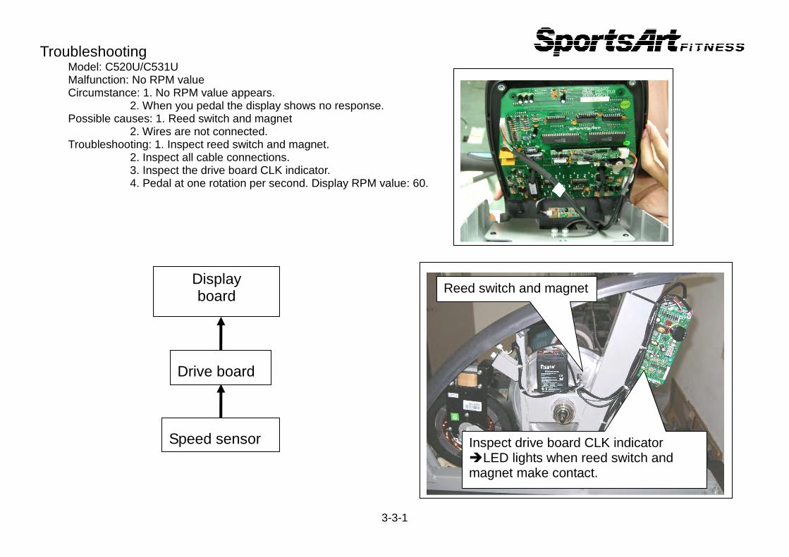
Troubleshooting Model: C520U/C531U Malfunction: No RPM value Circumstance: 1. No RPM value appears. 2. When you pedal the display shows no response. Possible causes: 1. Reed switch and magnet 2. Wires are not connected. Troubleshooting: 1. Inspect reed switch and magnet. 2. Inspect all cable connections. 3. Inspect the drive board CLK indicator. 4. Pedal at one rotation per second. Display RPM value: 60.
3-3-1
Display board
Drive board
Speed sensor
Reed switch and magnet
Inspect drive board CLK indicator �LED lights when reed switch and magnet make contact.

Troubleshooting Model: C520U/C531U Malfunction: No resistance Circumstance: Pedal the unit. There is no resistance. Possible causes: 1. Wires are not connected. 2. Drive board is defective. Troubleshooting: 1. Inspect all cable connections. 2. Inspect whether RPM value appears when one pedals. If not, inspect the reed switch wires. 3. Inspect whether alternator can start unit. 4. Inspect drive board fuse. Inspect whether the drive board emits voltage to
the electro-magnet. 5. Inspect the electro-magnet wires and whether the electro-magnet attracts metal.
3-4-1
Drive board
Display board
Alternator
Reed switch
Electro- magnet
F1 fuse
Inspect drive board CON2 voltage LEV 5 � 6.3V
LEV 15� 10V

Troubleshooting Model: C520U/C531U Malfunction: Resistance is excessive. Circumstance: Pedal the bike; resistance is excessively heavy. Possible causes: 1. There is an electrical short in the cables. 2. Drive board components have an electrical short. Troubleshooting: 1. Inspect all cable connections. Inspect cables for damage. 2. Inspect drive board power components for a short. 3. Replace the drive board.
3-5-1
Drive board
Display board
Electro- magnet
Inspect IGBTs for a short

Troubleshooting Model: C520U/C531U Malfunction: Telemetry heart rate malfunction Circumstance: Heart rate value does not appear. Possible causes: 1. Telemetry transmitter batteries. 2. Heart rate receiver board malfunction. 3. Environmental interference, possibly from lights or speakers. Troubleshooting: 1. Replace the heart rate transmit- ter strap or its batteries. 2. Inspect heart rate receiver board connections. 3. Inspect the HTR board LEDs.
3-6-1
Display board
HR receiver board
Telemetry heart rate receiver board

Troubleshooting Model: C531U Malfunction: HTR heart rate malfunction Circumstance: Hold HTR contacts with both hands; Heart rate values are incorrect. Possible causes: 1. HTR wires are not connected. 2. HTR board is defective. 3. Display wires are not connected. Troubleshooting: 1. Inspect display wire connections. 2. Inspect bridge board HTR wires. 3. Inspect HTR contact wires. 4. Inspect HTR board indicators. 5. Replace the HTR board.
3-7-1
Display board
HTR board
SE
NS
OR
-L
SE
NS
OR
-R
HTR board indicator LEDs LED Name Explanation
LED1 Telemetry Flashes to indicate incoming telemetry signal. LED2 HTR contact Lights to indicate hands on contact plates. LED3 HTR output Flashes to indicate incoming HTR (contact)
signal. LED4 Heart rate
signal output Flashes to indicate heart rate signal output to the display

4-1. Mechanical Maintenance Schedule - C531U/C520U
Item Inspect and maintain Daily Weekly Monthly 1 Wipe clean unit
exterior. ◎
2 Level unit. ◎
3 Inspect screws. ◎
4 Inspect pedals for noise.
◎
5 Inspect seat height adjustment.
◎
6 Inspect seat fore/aft adjustment.
◎
4-1-1