ca-nv awwa 2013 annual fall...
TRANSCRIPT

Well Pump Selection To Match
System Hydraulics
John Fawcett, PE
Luhdorff and Scalmanini
Consulting Engineers
CA-NV AWWA 2013 ANNUAL FALL CONFERENCE

GROUNDWATER USE
• Well pumps used in over 10,000 public supply groundwater wells in CA
• Pumping groundwater accounts for 25 to 40% of CA’s water supply
• Nearly 15 billion gallons of groundwater per day in CA

GOAL OF PRESENTATION
• To educate participants using real world examples that inform them of the importance of efficiently well pump selection
• Provide the participants with the tools needed to select a well pump should they be involved with equipping one of the 10,000 CA public supply groundwater well projects
IMPORTANCE OF
UNDERSTANDING WELL PUMPING
HYDRAULICS• Pumping Groundwater is a Major Cost For
Many Cities and Water Districts
• Head losses account for one third of all energy
• Good Hydraulic Design = Less Energy = Less Greenhouse Emissions
Presentation Content
• Well & Well Pump Hydraulics
• Well Pump Selection
• VFD & Well Pump Performance
• Examples
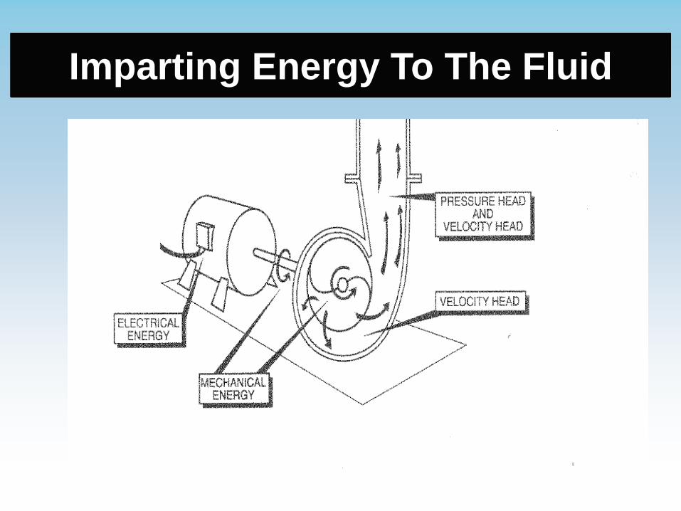
Imparting Energy To The Fluid

Eye Of An Enclosed Impeller

Sectional View Of A Pump Bowl
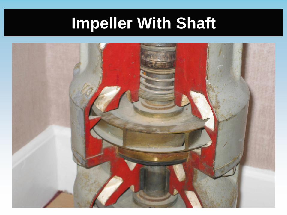
Impeller With Shaft
Submersible Pumps
General Uses:
• Water well duty
Advantages:
• Wide range of capacities
Disadvantages:
• Minimum flow required for cooling motor
• Power cable vulnerability
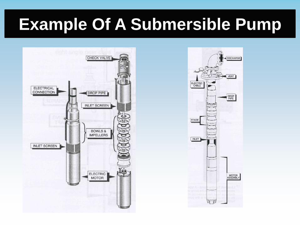
Example Of A Submersible Pump

Discharge Head For Submersible
Pumps

Submersible Pump and Motor

Vertical Lineshaft Pumps
General Uses:
• Water well duty
• Booster duty
Advantages:
• Wide range of capacities and heads
• High operating efficiency
Disadvantages:
• Minimum operational speed required to cool motor and bowl
assembly
• Well alignment concerns

Example Of A Lineshaft Pump

Deep Well Product Lubricated
Lineshaft Pump

Water Lube Lineshaft Pump

Submersible and Lineshaft Pumps
Advantages and Disadvantages
Variable Submersible Turbine
1. Noise X
2. Motor Serviceability X
3. Initial Capital Cost X
4. Operating Cost (Electrical) X
5. Service Life X
6. Flexibility (Use of Different Primer
Movers)
X
7. Well Alignment Problem X
X Denotes Advantage

Why is Proper Well Pump Selection
Important?
• Well Pump Stations Have a High
Capital Cost
• Reliability
• Operational Flexibility
• Efficiency/Operational Cost
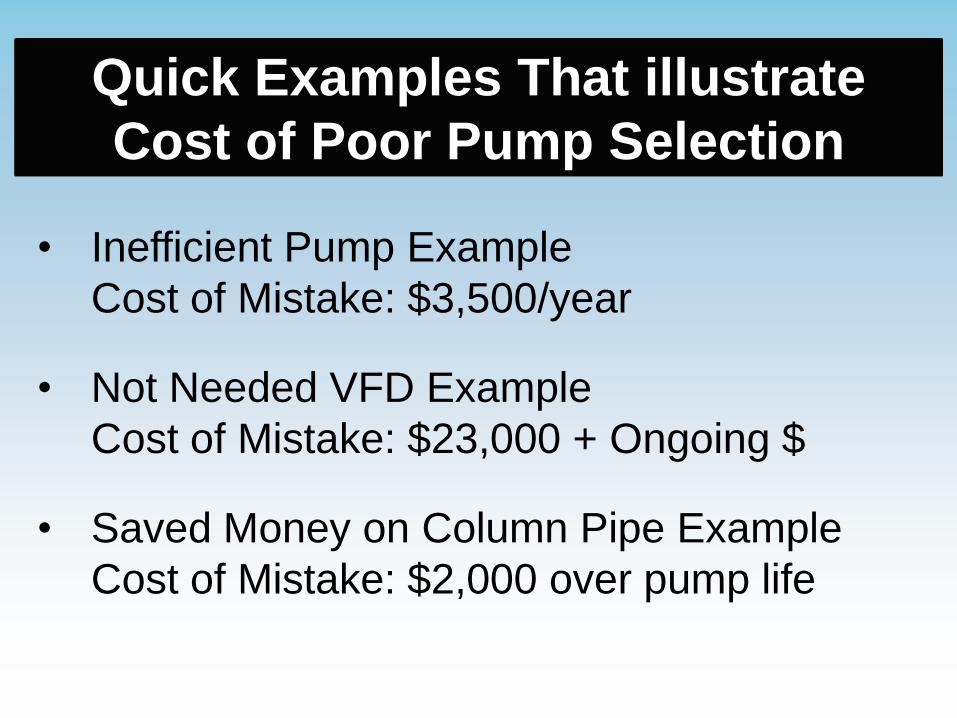
Quick Examples That illustrate
Cost of Poor Pump Selection
• Inefficient Pump Example
Cost of Mistake: $3,500/year
• Not Needed VFD Example
Cost of Mistake: $23,000 + Ongoing $
• Saved Money on Column Pipe Example
Cost of Mistake: $2,000 over pump life
Well/Aquifer Data Link To Pump
Selection
• Water Level
• Well Design Capacity
• Well Tests/Specific Capacity
• Mutual Pumping Interference
• Well Physical Characteristics
• Well Plumbness and Alignment Tests

Typical Well Pump
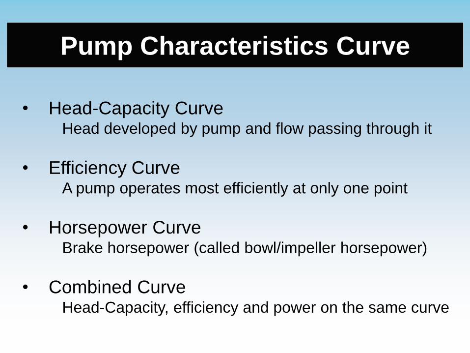
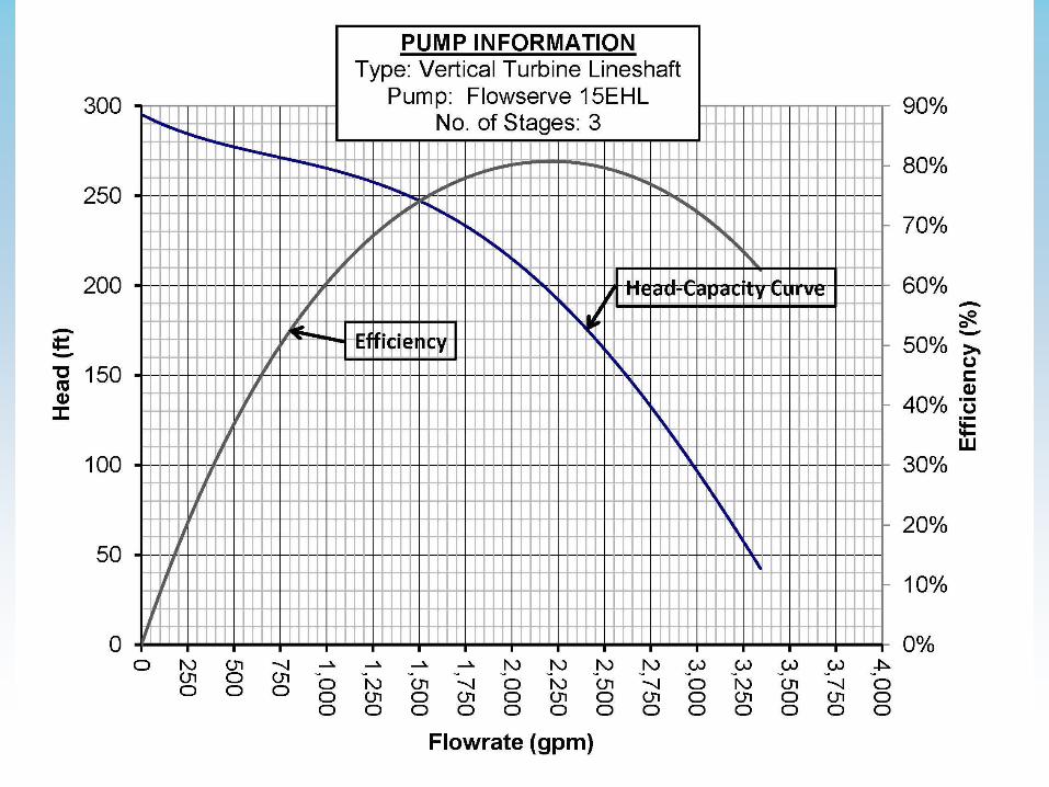
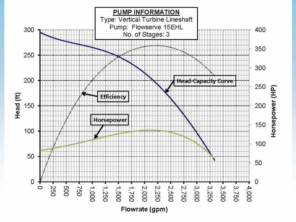
Pump Characteristics Curve
• Head-Capacity CurveHead developed by pump and flow passing through it
• Efficiency CurveA pump operates most efficiently at only one point
• Horsepower CurveBrake horsepower (called bowl/impeller horsepower)
• Combined CurveHead-Capacity, efficiency and power on the same curve

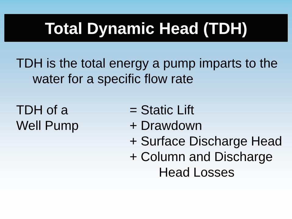
Total Dynamic Head (TDH)
TDH is the total energy a pump imparts to the
water for a specific flow rate
TDH of a = Static Lift
Well Pump + Drawdown
+ Surface Discharge Head
+ Column and Discharge
Head Losses

System Curves
Definition: Graphical plot of the TDH required by the
system for a change in flow rate
Used Two Ways:
• One-point Method – Conditions Not Changing
Pump not expected to change over time (e.g.,
pumping from tank to reservoir)
• Two-point Method – Pump Conditions
Changing
(e.g., seasonal lowering of water level in well)
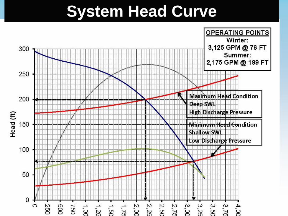
System Head Curve

Well Pump Acquisition
• Specify Well Pump Operation Points Using
Two-point Method
• Specify Pump Supplier Provide All Pump
System Appurtenances
• Require Certified Factory Curve
• Specify OPE & Vibration Testing by
Independent Contractor
Variable Frequency Drive (VFD)
VFD Advantages
• Potential Power Savings
• Enhances Operational Flexibility
• Soft/Start Lowers In-rush Current &
Reduces Mechanical Stress
• Reduces Chance of Water Hammer

Throttle Control Is Not Efficient
Shutting Valves To Control Flow Wastes EnergyReference: USDA ,MT-14 , January 2010
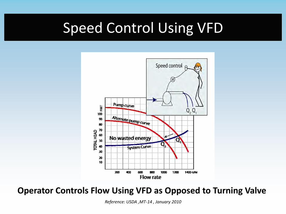
Speed Control Using VFD
Operator Controls Flow Using VFD as Opposed to Turning ValveReference: USDA ,MT-14 , January 2010

Affinity Laws and VFDs
Laws of affinity express mathematical
relationship between flow, pump speed, head
and power consumption for well pumps
Where
Q = Capacity, GPM
H = Total Head, Feet
BHP = Brake
Horsepower
N = Pump Speed, RPM
Affinity Laws and VFDs
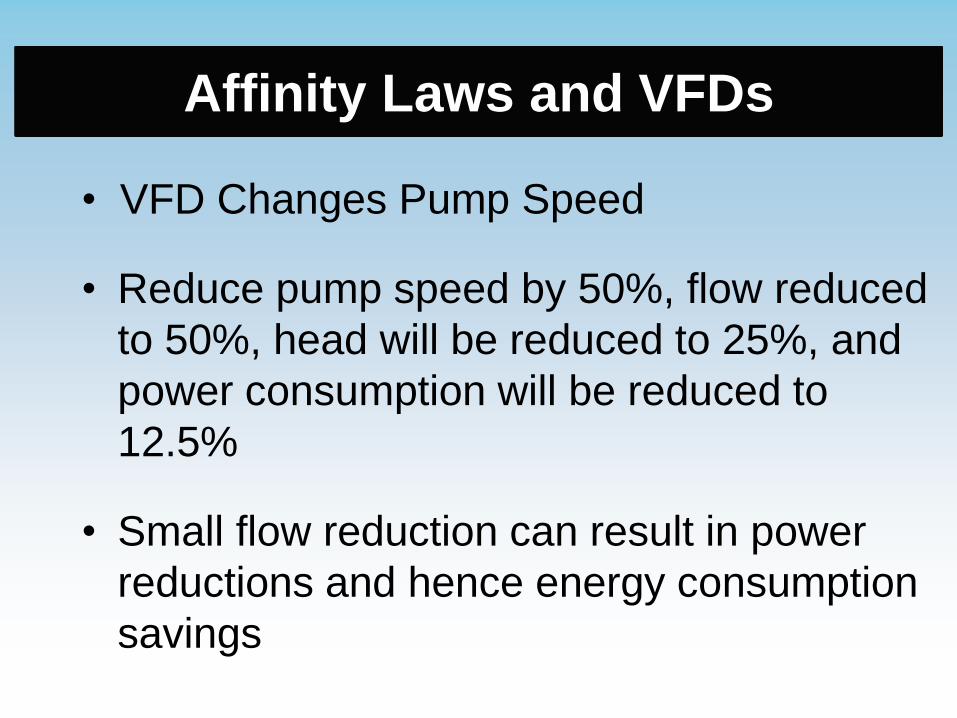
• VFD Changes Pump Speed
• Reduce pump speed by 50%, flow reduced
to 50%, head will be reduced to 25%, and
power consumption will be reduced to
12.5%
• Small flow reduction can result in power
reductions and hence energy consumption
savings

Working Examples

Typical Well Pump

Example TDH Calculations
Static Water Level (no pumping) = 100 feet
Drawdown = 30 feet
Discharge pressure = 60 PSI
Pump bowl settling below ground = 200 feet
800 GPM, 8” column pipe, 1.5” shaft with a type A discharge
head
Find: Pump Total Dynamic Head required, TDH
Formula: TDH = Static Lift + Drawdown + Friction + Discharge
Pressure

TDH Solution
Solution:
Determine the column and discharge head friction loss for a deep well
turbine are determined.
Column Hf = (2.6 feet/100‘) x 200 feet = 5.2 feet
Discharge head Hf for 8” Type A = 0.3 feet
TDH = Static Lift + Drawdown + Friction + Discharge Pressure
= 100’ + 30‘ + (60 PSI x 2.31’/PSI) + 5.2 ft + 0.3 ft
= 274 feet
NOTE: For a submersible well pump, the friction loss in the discharge pipe
obtained using the same length of straight pipe made of the same
material (no shaft or oil tube in the column pipe to cause extra friction)
Power Delivered In Three Places
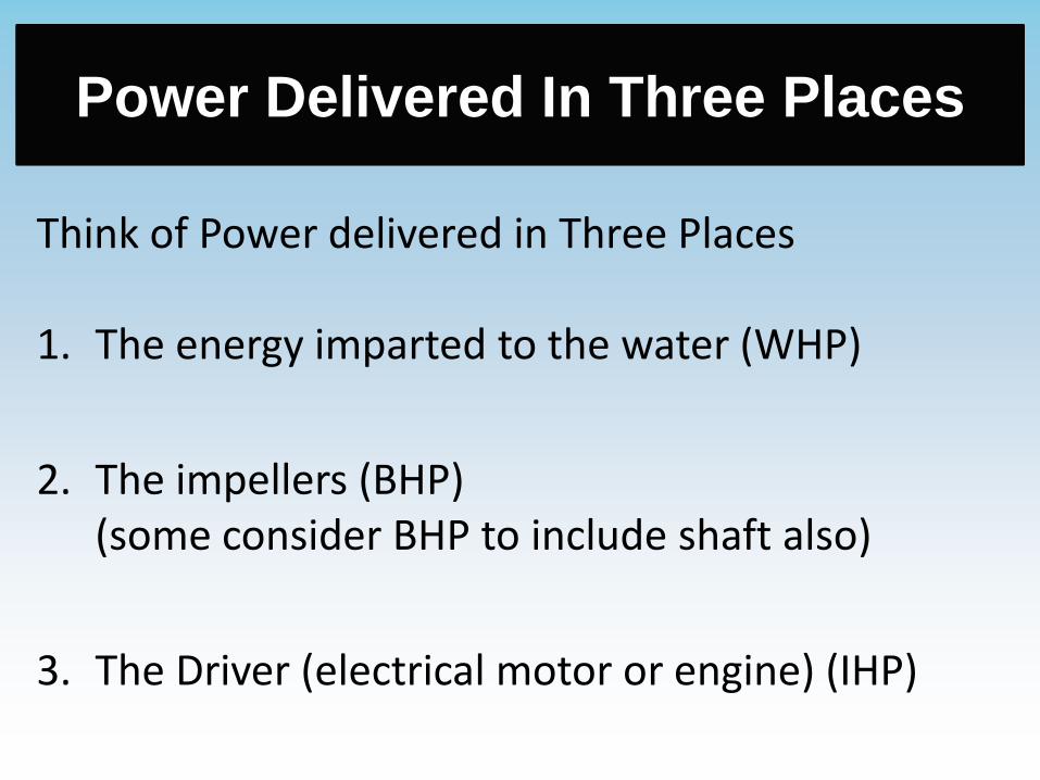
Think of Power delivered in Three Places
1. The energy imparted to the water (WHP)
2. The impellers (BHP)(some consider BHP to include shaft also)
3. The Driver (electrical motor or engine) (IHP)

Example Water Horsepower (WHP)
Where the flow rate is measured in Gallons Per Minute (GPM)
and the Total Dynamic Head (TDH) is measured in feet:
Find: Water Horsepower (WHP)
Formula: WHP =
Solution: WHP =
= 55.4 HP
Brake Horsepower (BHP)
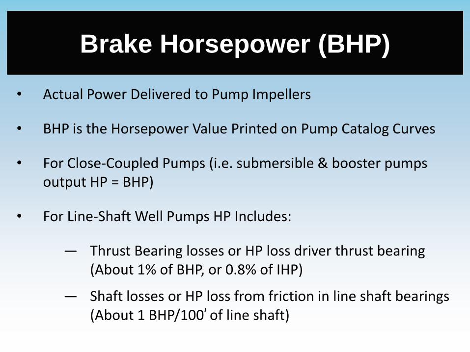
• Actual Power Delivered to Pump Impellers
• BHP is the Horsepower Value Printed on Pump Catalog Curves
• For Close-Coupled Pumps (i.e. submersible & booster pumps output HP = BHP)
• For Line-Shaft Well Pumps HP Includes:
— Thrust Bearing losses or HP loss driver thrust bearing (About 1% of BHP, or 0.8% of IHP)
— Shaft losses or HP loss from friction in line shaft bearings (About 1 BHP/100‘ of line shaft)
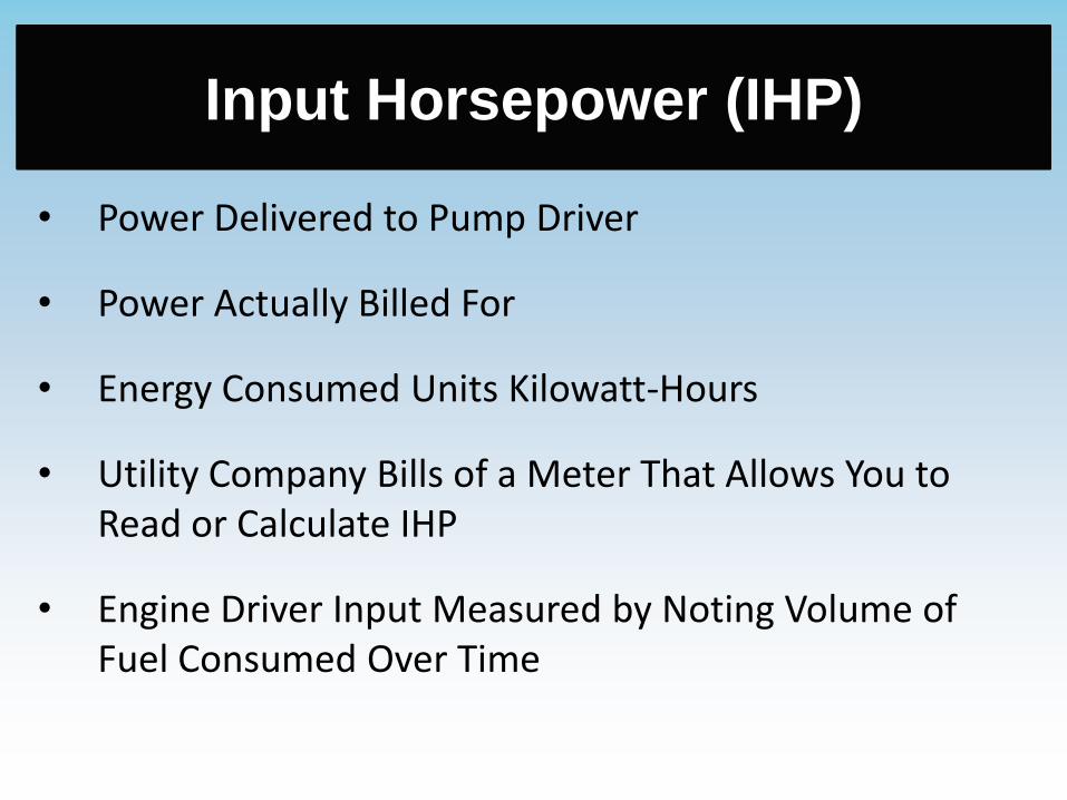
Input Horsepower (IHP)
• Power Delivered to Pump Driver
• Power Actually Billed For
• Energy Consumed Units Kilowatt-Hours
• Utility Company Bills of a Meter That Allows You to Read or Calculate IHP
• Engine Driver Input Measured by Noting Volume of Fuel Consumed Over Time

Efficiencies
• Impellers Don’t Convert All Mechanical to Hydraulic Energy Typical: 70% (+)
• Vertical Turbine Motors Don’t Convert All Electrical to Mechanical Energy:
Standard Efficient: 88 – 92%
Premium Efficient: 93 – 96%
Submersibles: 83 – 87%
• Engine Drivers Don’t Convert All Input Energy (Fuel) Into Mechanical Energy
Typical: Internal Combustion Engine = 33%

Determine Motor Size Example
Given: A well pump
Floway 10LKM at 1770 RPM, impeller trim “A”
Flow rate (Q) = 500 GPM
Total Dynamic Head (TDH) = 150 feet
Shaft HP Loss = 2 HP
Thrust = 0.5 HP
Find: a) WHP
b) BHP
c) Required Motor Size
d) Estimated Input HP to the Pumping Plant (IHP)
e) Overall Pumping Plant Efficiency (OPE)
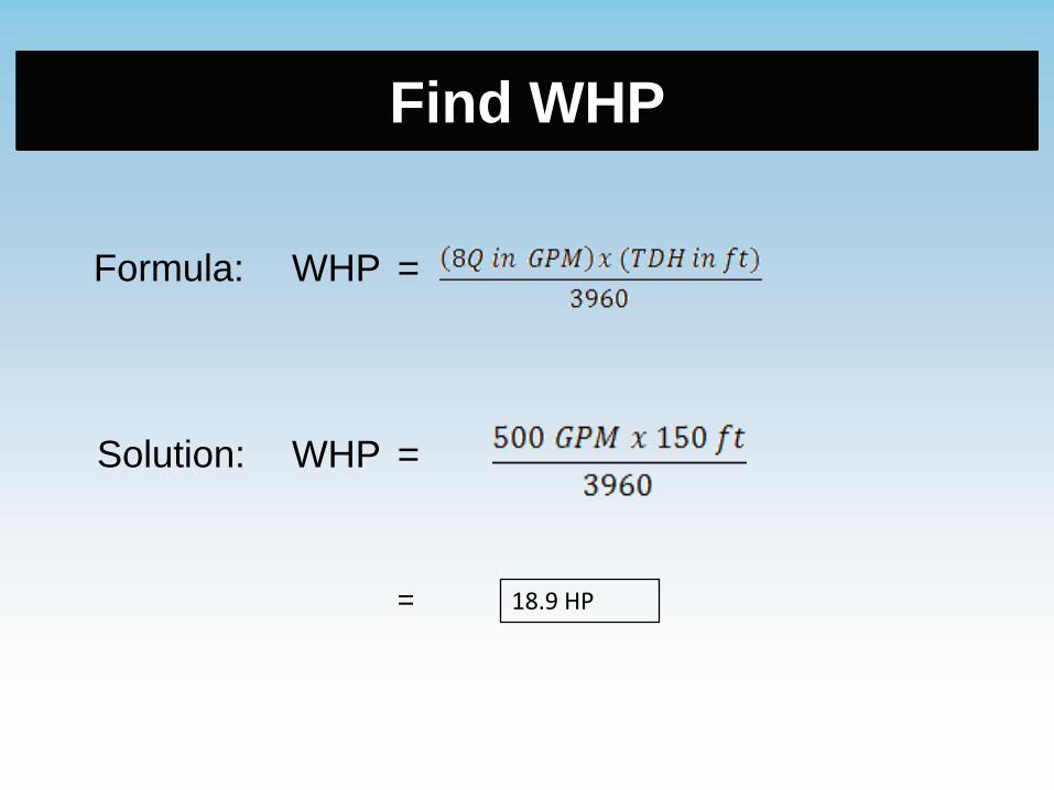
Find WHP
Formula: WHP =
Solution: WHP =
= 18.9 HP

Find BHP
Formula: BHP =
p VI-38, TDH, Ei = 78%
Solution: BHP =
= 24.3 HP

BHP From Pump Curve
One can determine the BHP directly from
the pump performance curve itself.
BHP = 8.1 per stage (impeller)
= 8.1/stage x 3 stages
= 24.3 HP
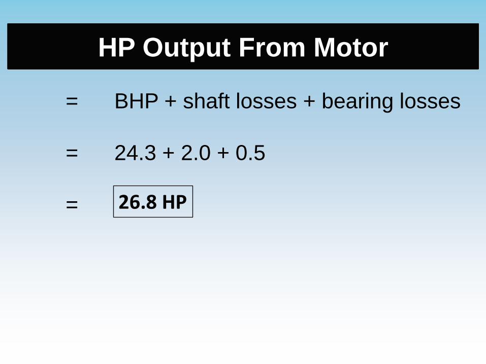
HP Output From Motor
= BHP + shaft losses + bearing losses
= 24.3 + 2.0 + 0.5
= 26.8 HP

Service Factor:
Don’t Overload Motor
1. A motor should not be overloaded by more than the service factor stamped on its nameplate
2. 25 HP motor having a service factor of 1.1 should not be loaded to greater than 25 HP x 1.1 = 27.5 HP
3. If there is no service factor on the motor nameplate, then do not overload motor
4. Conclusion: In this case choosing a 25 HP motor is OK, but LSCE does not usually recommend exceeding nameplate HP

Input HP to the Motor
=
=
=
= 30.1 HP
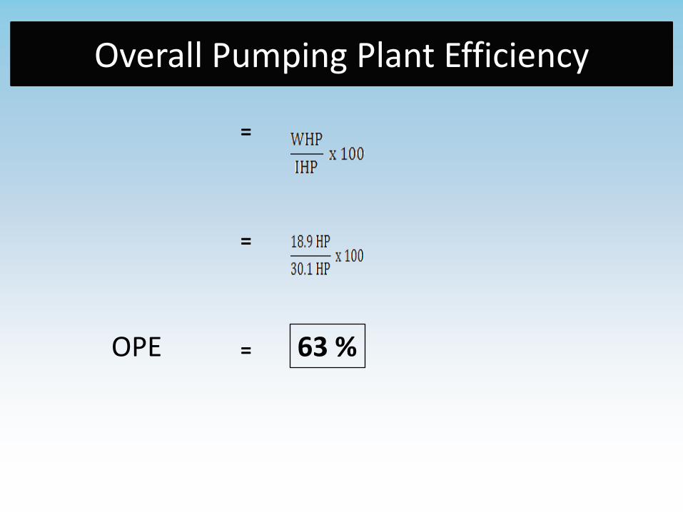
Overall Pumping Plant Efficiency
=
=
= 63 %OPE

Questions