cable current transformers types: kolma,...
TRANSCRIPT
CABLE CURRENT TRANSFORMERStypes: KOLMA, KOLA, KOKM, KOKU, KOLT
Catalogue
2 ABB
CONTENT page
1. KOLMA, KOLADescription ........................................................................... 3How to select the correct residual current transformers ..... 3Technical data ...................................................................... 4Installation ............................................................................ 4Ordering data ....................................................................... 6Overall dimensions ............................................................... 6
2. KOKM ...................................................................................... 9Technical data ...................................................................... 9Ordering data ..................................................................... 10Instruction for installation .................................................. 10Overall dimensions ............................................................. 12
3. KOKU..................................................................................... 17Technical data .................................................................... 17Overall dimensions ............................................................. 19
4. KOKM (for ZX panells) ......................................................... 22Technical data .................................................................... 22Overall dimensions ............................................................. 23
5. KOLT ...................................................................................... 31Dimensional drawing .......................................................... 31Technical data .................................................................... 32
3ABB
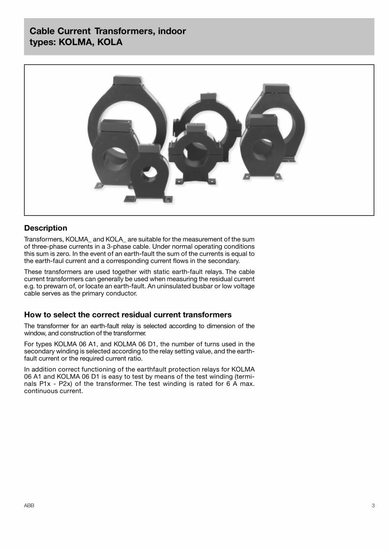
Cable Current Transformers, indoortypes: KOLMA, KOLA
DescriptionTransformers, KOLMA_ and KOLA_ are suitable for the measurement of the sumof three-phase currents in a 3-phase cable. Under normal operating conditionsthis sum is zero. In the event of an earth-fault the sum of the currents is equal tothe earth-faul current and a corresponding current flows in the secondary.
These transformers are used together with static earth-fault relays. The cablecurrent transformers can generally be used when measuring the residual currente.g. to prewarn of, or locate an earth-fault. An uninsulated busbar or low voltagecable serves as the primary conductor.
How to select the correct residual current transformersThe transformer for an earth-fault relay is selected according to dimension of thewindow, and construction of the transformer.
For types KOLMA 06 A1, and KOLMA 06 D1, the number of turns used in thesecondary winding is selected according to the relay setting value, and the earth-fault current or the required current ratio.
In addition correct functioning of the earthfault protection relays for KOLMA06 A1 and KOLMA 06 D1 is easy to test by means of the test winding (termi-nals P1x - P2x) of the transformer. The test winding is rated for 6 A max.continuous current.
4 ABB
Type Window diam. Construction Weightmm kg
KOLMA 06 A1 90 Ring core, multi-tap secondary 7.0KOLMA 06 A2 58 Ring core 2.9
KOLMA 06 B2 100 Ring core 5.4
KOLMA 06 D1 180 Ring core, multi-tap secondary 11.5KOLMA 06 D2 180 Ring core 11.4
KOLA 06 B2 100 Split ring core 6.0KOLA 06 D2 180 Split ring core 11.0
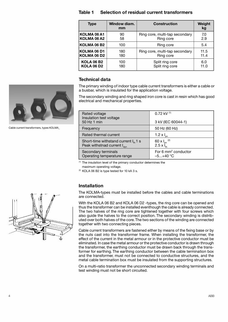
Technical dataThe primary winding of indoor type cable current transformers is either a cable ora busbar, which is insulated for the application voltage.
The secondary winding and ring shaped iron core is cast in resin which has goodelectrical and mechanical properties.
Rated voltage 0.72 kV (1)
Insulation test voltage50 Hz 1 min 3 kV (IEC 60044-1)
Frequency 50 Hz (60 Hz)
Rated thermal current 1.2 x Ipn
Short-time withstand current Ith 1 s 60 x Ipn (2)
Peak withstnad current Idyn 2.5 x IthSecondary terminals For 6 mm2 conductorOperating temperature range –5...+40 °C
(1) The insulation level of the primary conductor determines themaximum operating voltage.
(2) KOLA 06 B2 is type tested for 10 kA 3 s.
Cable current transformers, types KOLMA_
InstallationThe KOLMA-types must be installed before the cables and cable terminationsare connected.
With the KOLA 06 B2 and KOLA 06 D2 -types, the ring core can be opened andthus the transformer can be installed eventhough the cable is already connected.The two halves of the ring core are tightened together with four screws whichalso guide the halves to the correct position. The secondary winding is distrib-uted over both halves of the core. The two sections of the winding are connectedtogether with two connecting pieces.
Cable current transformers are fastened either by means of the fixing base or bythe nuts cast into the transformer frame. When installing the transformer, theeffect of the current in the metal armour or in the protective conductor must beeliminated. In case the metal armour or the protective conductor is drawn throughthe transformer, the earthing conductor must be drawn back through the trans-former for earthing. The earthing conductor between the cable termination boxand the transformer, must not be connected to conductive structures, and themetal cable termination box must be insulated from the supporting structures.
On a multi-ratio transformer the unconnected secondary winding terminals andtest winding must not be short circuited.
Table 1 Selection of residual current transformers
5ABB
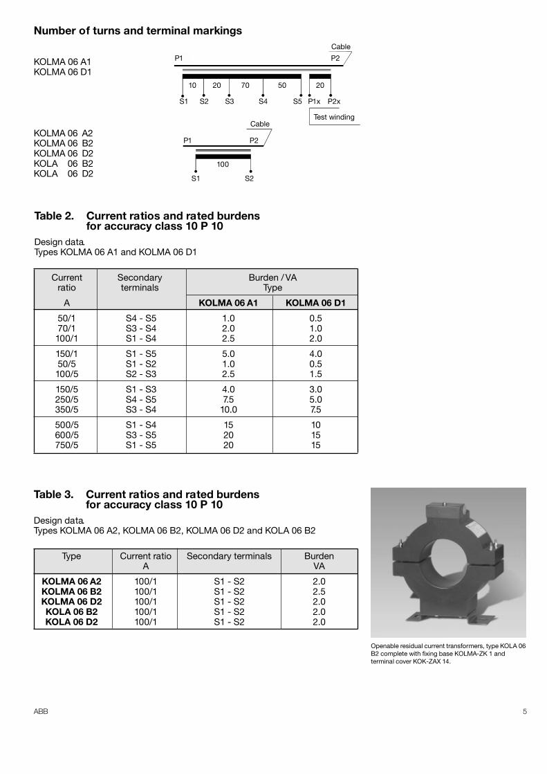
Table 3. Current ratios and rated burdensfor accuracy class 10 P 10
Design data.Types KOLMA 06 A2, KOLMA 06 B2, KOLMA 06 D2 and KOLA 06 B2
Type Current ratio Secondary terminals BurdenA VA
KOLMA 06 A2 100/1 S1 - S2 2.0KOLMA 06 B2 100/1 S1 - S2 2.5KOLMA 06 D2 100/1 S1 - S2 2.0KOLA 06 B2 100/1 S1 - S2 2.0KOLA 06 D2 100/1 S1 - S2 2.0
Table 2. Current ratios and rated burdensfor accuracy class 10 P 10
Design data.Types KOLMA 06 A1 and KOLMA 06 D1
Current Secondary Burden / VAratio terminals Type
A KOLMA 06 A1 KOLMA 06 D1
50/1 S4 - S5 1.0 0.570/1 S3 - S4 2.0 1.0100/1 S1 - S4 2.5 2.0
150/1 S1 - S5 5.0 4.050/5 S1 - S2 1.0 0.5100/5 S2 - S3 2.5 1.5
150/5 S1 - S3 4.0 3.0250/5 S4 - S5 7.5 5.0350/5 S3 - S4 10.0 7.5
500/5 S1 - S4 15 10600/5 S3 - S5 20 15750/5 S1 - S5 20 15
S1 S2
100
P1 P2
S1 S2 S3 S4 S5 P1x P2x
50 20702010
P1 P2
CableTest winding
Cable
Number of turns and terminal markings
KOLMA 06 A1KOLMA 06 D1
KOLMA 06 A2KOLMA 06 B2KOLMA 06 D2KOLA 06 B2KOLA 06 D2
Openable residual current transformers, type KOLA 06B2 complete with fixing base KOLMA-ZK 1 andterminal cover KOK-ZAX 14.
6 ABB
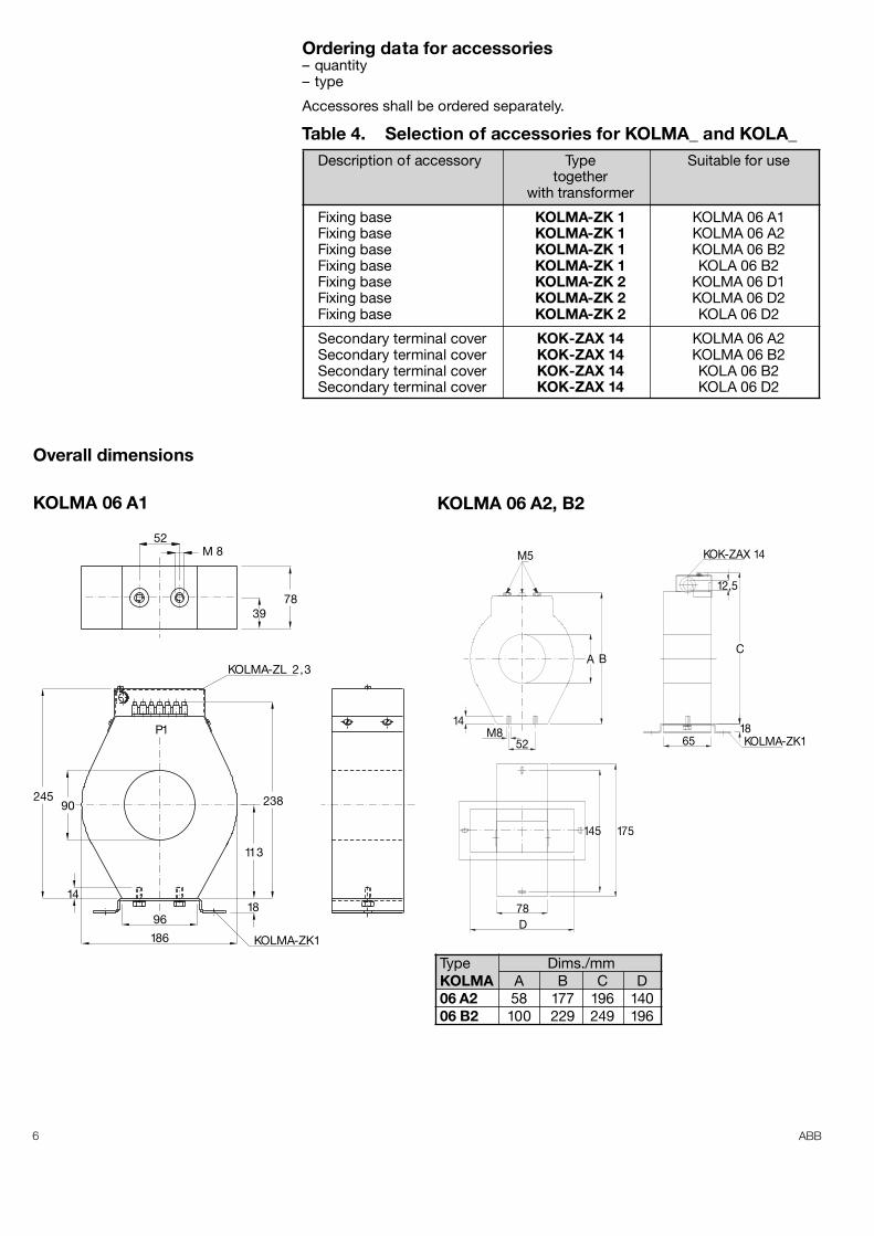
KOLMA 06 A1 KOLMA 06 A2, B2
Type Dims./mmKOLMA A B C D06 A2 58 177 196 14006 B2 100 229 249 196
Table 4. Selection of accessories for KOLMA_ and KOLA_
Ordering data for accessories– quantity– type
Accessores shall be ordered separately.
Overall dimensions
P1
90
14
245
113
238
186
9618
KOLMA-ZK1
52M 8
3978
KOLMA-ZL 2,3
M5
14M8
52
A B
KOK-ZAX 14
12,5
C
18KOLMA-ZK165
175145
78D
Description of accessory Type Suitable for usetogether
with transformer
Fixing base KOLMA-ZK 1 KOLMA 06 A1Fixing base KOLMA-ZK 1 KOLMA 06 A2Fixing base KOLMA-ZK 1 KOLMA 06 B2Fixing base KOLMA-ZK 1 KOLA 06 B2Fixing base KOLMA-ZK 2 KOLMA 06 D1Fixing base KOLMA-ZK 2 KOLMA 06 D2Fixing base KOLMA-ZK 2 KOLA 06 D2
Secondary terminal cover KOK-ZAX 14 KOLMA 06 A2Secondary terminal cover KOK-ZAX 14 KOLMA 06 B2Secondary terminal cover KOK-ZAX 14 KOLA 06 B2Secondary terminal cover KOK-ZAX 14 KOLA 06 D2
7ABB
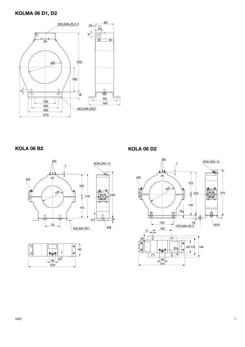
KOLMA 06 D1, D2
1518
17
2325
80KOLMA-ZL2,3
KOLMA-ZK2
270190150130 145
115
140
335180
P1
KOK-ZAX 14M5
M5 P1
7
52
100
KOLMA-ZK1
109
110
219 238
18
M8
14
85
228
2036
P1
a b
ba
1 2
KOK-ZAX 147
180
KOLMA-ZK 2
M5
M5
153
293
16
140
315
3
M1018150
13011
20
31536
20 85 115 145
KOLA 06 B2 KOLA 06 D2
8 ABB
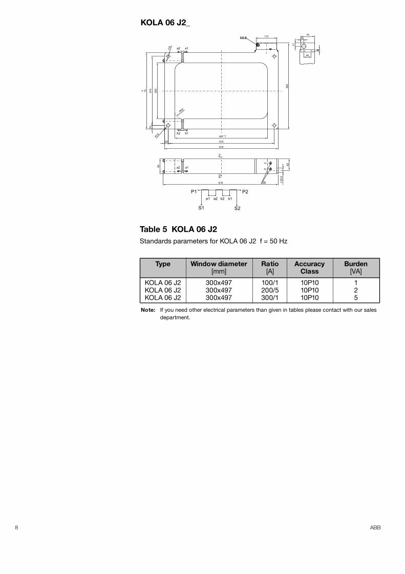
Table 5 KOLA 06 J2Standards parameters for KOLA 06 J2 f = 50 Hz
Type Window diameter Ratio Accuracy Burden[mm] [A] Class [VA]
KOLA 06 J2 300x497 100/1 10P10 1KOLA 06 J2 300x497 200/5 10P10 2KOLA 06 J2 300x497 300/1 10P10 5
Note: If you need other electrical parameters than given in tables please contact with our salesdepartment.
S1
P1 P2
S2
P1
P2
a1 a2 b2 b1
90
113M6
497 0+3
570
610
R40
R14
20
30
0
37
0
4 10
20
46
2
75
40
16
17
6
a1ø15
a2
b2 b1
a2 a1
62
22
,5ø
S1
S2
M5619
KOLA 06 J2_
9ABB
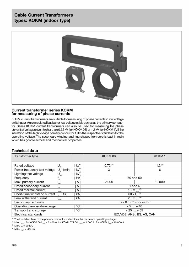
Cable Current Transformerstypes: KOKM (indoor type)
Technical dataTransformer type KOKM 06 KOKM 1
Rated voltage Um [ kV ] 0.72 (1) 1.2 (1)
Power frequency test voltage Up 1min [ kV ] 3 6Lighting test voltage Upp [ kV ] - -Frequency fn [ Hz ] 50 and 60Max. primary current Ipn [ A ] 2 000 10 000Rated secondary current Isn [ A ] 1 and 5Rated thermal current Icont [ A ] 1,2 x Ipn
(2)
Short-time withstand current Ith 1s [ kA ] 60 x Ipn (3)
Peak withstand current Idyn [ kA ] 2,5 x Ith (4)
Secondary terminals For 6 mm2 conductorOperating temperature range [ °C ] - 5 … + 40Transport and storage [ °C ] - 25 … + 55Electrical standards IEC, VDE, ANSI, BS, AS, CAN
(1) The insulation level of the primary conductor determines the maximum operating voltage.(2) Max. Icont for KOKM 06 Icont = 2 400 A, for KOKU 072 G4 Icont = 1 000 A, for KOKM Icont= 10 000 A(3) Max. Ith = 90 kA,(4) Max. Idyn = 225 kA
Current transformer series KOKMfor measuring of phase currentsKOKM current transformers are suitable for measuring of phase currents in low voltageswitchgear. An uninsulated busbar or low voltage cable serves as the primary conduc-tor. Series KOKM current transformers can also be used for measuring the phasecurrent at voltages even higher than 0,72 kV (for KOKM 06) or 1,2 kV (for KOKM 1), if theinsulation of the high voltage primary conductor fulfils the respective standards for theoperating voltage. The secondary winding and ring shaped iron core is cast in resinwhich has good electrical and mechanical properties.
10 ABB
Instructions for installationMounting of the cable current transformers
The cable current transformer may be installed either in vertical or in horizontal posi-tion. It can be mounted either by using bottom inserts or by using a separate fixingbase, which in turns is fixed to the bottom inserts. When using the bottom inserts formounting, the screws (M8) shall not be tightened in excess of the nominal torque; 9Nm, for the screws (M6) 3.3 Nm, otherwise damage may occur. Use a torque span-ner if necessary. The current transformer can be fastened to the cable which acts asprimary conductor by means of a special fixing piece. In such cases it must beinsured that the cable endures the strain caused by the weight of the transformer,especially in circumstances where vibration is involved. The secondary terminalscrews, size M5, must not be tightened in excess of 2.5 Nm (M4 1.0 Nm).
Fastening of the primary cable
The cable acting as primary winding shall be entered through the opening in thecable current transformer. This must be done before the cable box belonging to thecable inserted through the primary opening is installed. If the cable box can beentered through the primary opening even when it is installed on the cable, theinstallation of the cable box can also be done before. With the KOLA 06 J2, thecable current transformer can be opened and thus the transformer can be in-stalled even though the cable is already connected. The two halves of the ring coreare tightened together with four screws which also guide the halves to the correctposition. The secondary winding is distributed over both halves of the core. Thetwo section of the winding are connected together with two connecting pieces.
Note:
The secondary terminals of the current transformer should never be left open-circuited, because in that case hazardous high voltages will be induced betweenthe secondary terminals.
Instructions for maintenance
Cable current transformers do not need to be maintained. However, excessive dust orother kind of dirt can be brushed off the transformer. Dirty transformers can be cleanedwith water, spirit, petrol or toluene. Traces of arcs and minor surface damages can beeasily removed with sandpaper after which the surface is to be treated with siliconepaste. Epoxy resin surfaces of the current transformer have also a high resistance tochemicals.
Ordering dataEnquires for these transformers should mention the following data:
1.Quantity,2.Type, (example: KOKM 1 DC 10 (1), KOKU 1 KL 12 (2), KOKM 06 J29 (3),
KOKU 072 G4 (4))3.Current ratio Ipn/Isn (A),4.Burden (VA),5.Accuracy class,6.Electrical standards,7. Window dimension (mm),8.Other limiting data such as instrument security, dimensions of transformer,
fixing of transformer (fixing base) etc.,9.Indoor or outdoor use.(1) Other name of Type for KOKM 1 you can choose from table 6.(2) Other name of Type for KOKU 1 you can choose from table 8.(3) Other name of Type for KOKM 06 you can choose from table 7.(4) Electrical parameters and window dimension for KOKU 072 G4 include table 9.
Terminal markings
P2S2S1
P1 P11S1 1S2
P22S22S1
P1S2S1
P2S3
one secondary windingexample: 100/1 [A/A]
multi-tap secondary windingexample: 50-100/1 [A/A]
two secondary windingsexample: 800/5/5 [A/A/A]
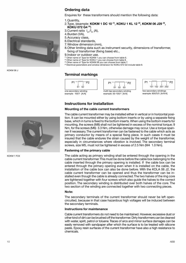
KOKM 06 J
KOKM 1 FC6
11ABB
The transformers can be used in areas, where the atmosphere includes corrosivegases such as sulphuric and nitrogenous compounds provided that secondary termi-nals and fixing base of the transformers have been ordered to meet the demands ofthe operating atmosphere. Instructions for repairing greater surface damages (suchas cracks) must be requested from the manufacturer.
Storage instructions
For current transformers, the allowed storage temperature is - 40°C …+ 55°C.The transformers shall be protected against direct sun light.
Package, Transport and Storage
Transformers assigned for export are packed in wooden cases lined with the asphaltbuilding paper. During the transport of transformers one should pay attention toproper position of wooden cases in accordance with inscription and marks given onthem and their protection against the influence of weather conditions. Transformershould be stored in dry and clean accommodations, protecting direct influence ofprecipitation and frost.
Warranty
The factory grants 24 months of warranty from the day of put to use of the trans-former, but no longer than 36 months from the day of sell. The warranty concernsonly manufacturing defects and does not include defects arose because of:
– improper transport,– improper storage,– not abiding of the instruction before installing and during operating
of the transformers,– improper selection of the transformer for the electric power system.
Procedure regarding the products after the end of their use.
The manufacturer gets back or indicates the store place for instrument transformersof its own production, which the period of use is finished, in order to their recycling.
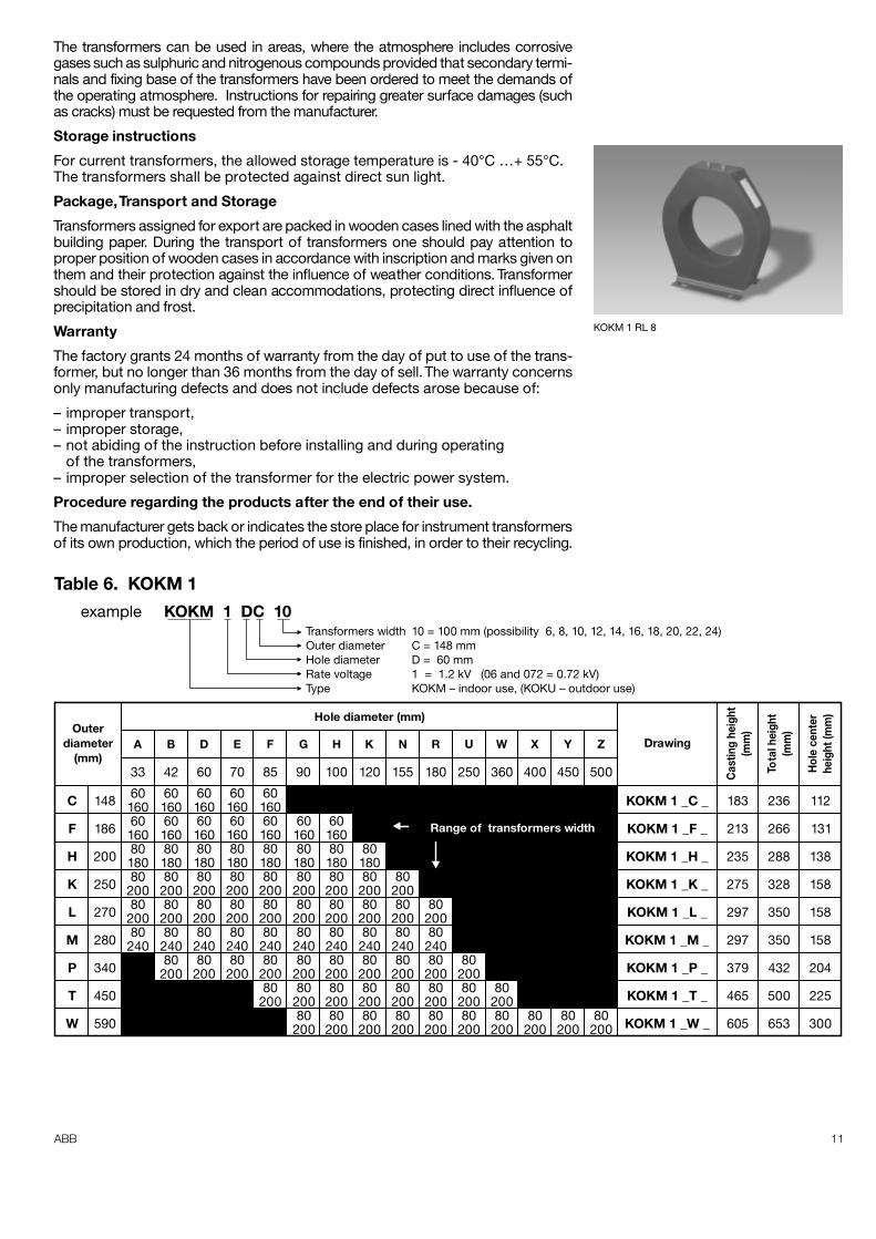
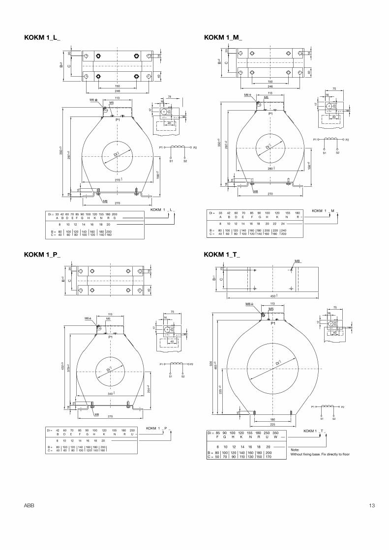
Table 6. KOKM 1example KOKM 1 DC 10
Transformers width 10 = 100 mm (possibility 6, 8, 10, 12, 14, 16, 18, 20, 22, 24)Outer diameter C = 148 mmHole diameter D = 60 mmRate voltage 1 = 1.2 kV (06 and 072 = 0.72 kV)Type KOKM – indoor use, (KOKU – outdoor use)
Outerdiameter
(mm)A B D E F G H K N R U W X Y Z
C
F
H
K
L
M
P
T
W
KOKM 1 _C _
KOKM 1 _F _
KOKM 1 _H _
KOKM 1 _K _
KOKM 1 _L _
KOKM 1 _M _
KOKM 1 _P _
KOKM 1 _T _
KOKM 1 _W _
112
131
138
158
158
158
204
225
300
236
266
288
328
350
350
432
500
653
183
213
235
275
297
297
379
465
605
60160601608018080
20080
20080
240
60160601608018080
20080
20080
24080
200
60160601608018080
20080
2008024080
200
148
33 42 60 70 85 90 100 120 155 180 250 360 400 450 500
186
200
250
270
280
340
450
590
60160601608018080
20080
2008024080
200
60160601608018080
20080
2008024080
20080
200
601608018080
20080
2008024080
20080
20080
200
601608018080
20080
2008024080
20080
20080
200
8018080
20080
2008024080
20080
20080
200
8020080
20080
24080
20080
20080
200
8020080
24080
20080
20080
200
8020080
20080
200
8020080
20080
20080
20080
200
Hole diameter (mm)
DrawingC
astin
g he
ight
(mm
)
Tota
l hei
ght
(mm
)
Hol
e ce
nter
heig
ht (m
m)
Range of transformers width
KOKM 1 RL 8
12 ABB
±2
S1 S2
P2P1
+20±2
±3±2
±2
6
40
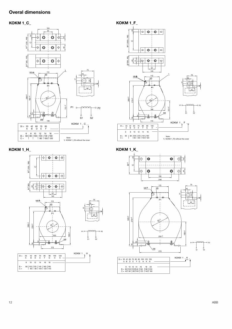
KOKM 1 _ C __
M8
M5
P1
Di = 33 42 60 70 85A B D E F
6 8 10 12 14 16B = 60 80 100 120 140 160C = 80 100 120
1) KOKM 1_C6 without the coverNote:
M61
1617
75
23
112
148
Di
14
183
18
236
113
1140
52124
C20
B
(12
0...1
60)
B
(60
...10
0)
±2
±2
P1
S1 S2
P2
P1
+30
M5
P1
M61
75
40
6
23
16
17
131
170
14
18
186
Di
213
±2
266
±3
113
140
52
1140
B
(60.
..80)
C
B
(100
0...1
60)
±2
20
KOKM 1 _ F __Di = 33 42 60 70 85 90 100
A B D E F G H
6 8 10 12 14 16
B = 60 80 100 120 140 160C = 60 80 100 120
M8
1) KOKM 1_F6 without the coverNote:
150
246
1440
20CB
±2
P1
S1
P1 P2
S2M8
M6
M5
Di = 33 42 60 70 85 90 100 120A B D E F G H K
8 10 12 14 16 18
B = 80 100 120 140 160 180C = 60 80 100 120 140
±2
+30
16
75
17
6
40
138200
170
14
18
Di
235±
2
288
±3
113
52
140
1140
B
(80)
±2
C
B
(100
...18
0)±2
KOKM 1 _ H _
P1
P1
S1
P2
S2
M5M6
M8
Di = 33 42 60 70 85 90 100 120 155A B D E F G H K N
8 10 12 14 16 18 20B = 80 100 120 140 160 180 200C = 40 60 80 100 120 140 160
±2
0-2
+30
16
75
640
17
23
158
270
Di
250
15
1827
5±2
328±
3
113
KOKM 1 _ K _
Overal dimensions
KOKM 1_C_ KOKM 1_F_
KOKM 1_H_ KOKM 1_K_
13ABB
P1
P1
S1
P2
S215
8
M5M6
M8
Di = 33 42 60 70 85 90 100 120 155 180 200A B D E F G H K N R S
8 10 12 14 16 18 20
B = 80 100 120 140 160 180 200C = 40 60 80 100 120 140 160
±2
+30
0-2
74
16
17
23
40
6270
270
Di
15
1829
7±235
0±3
113
150
246
20CB
±2
1440
KOKM 1 _ L _
S1
P2
S2
P1
P1
M5M6
M8
Di = 33 42 60 70 85 90 100 120 155 180A B D E F G H K N R
8 10 12 14 16 18 20 22 24
B = 80 100 120 140 160 180 200 220 240C = 40 60 80 100 120 140 160 180 200
±2
0-2
+30
16
75
23
17
6
40
158
280
270
15
1829
7±2
350
±3
Di
113
150
246
1440
20CB
±2
KOKM 1 _ M _
0-3
M8
450
15CB
±1
P1
P1
S1 S2
P2
M6 M5
M8
Di = 42 60 70 85 90 100 120 155 180 250B D E F G H K N R U
8 10 12 14 16 18 20
B = 80 100 120 140 160 180 200C = 40 60 80 100 120 140 160
±2
+30
0-2
16
75
23
17
6
40
204
270
340
15
1837
9±2
432±
3
Di
113
20CB
±2
1440
KOKM 1 _ P _
P1
P1
S1
P2
S2
M6M5
Di = 85 90 100 120 155 180 250 350F G H K N R U W
8 10 12 14 16 18 20
B = 80 100 120 140 160 180 200C = 50 70 90 110 130 150 170
+40
Note:Without fixing base. Fix directly to floor
75
1617 23
40
6
180
225
Di
15
225
±3
465
±3500
113
KOKM 1 _ T _
KOKM 1_L_ KOKM 1_M_
KOKM 1_P_ KOKM 1_T_
14 ABB
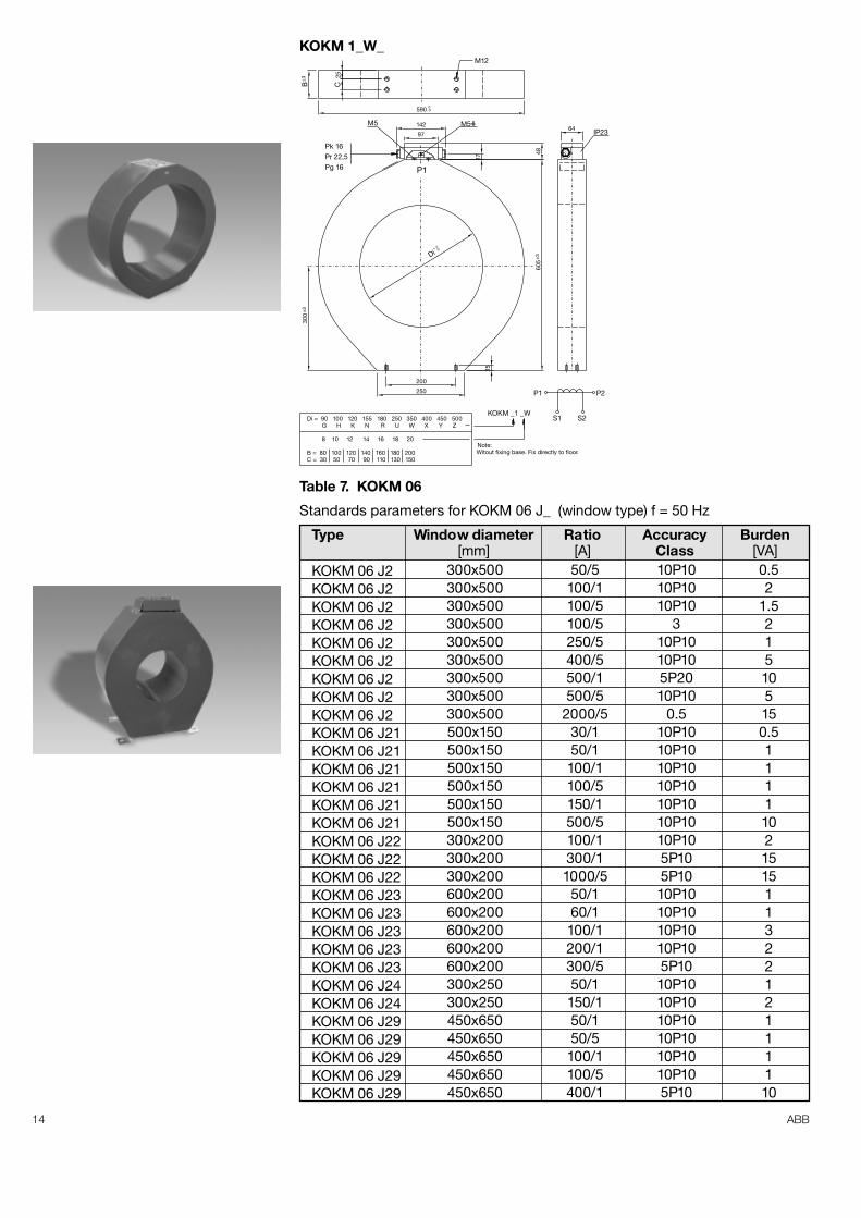
Table 7. KOKM 06
Standards parameters for KOKM 06 J_ (window type) f = 50 Hz
Type Window diameter Ratio Accuracy Burden[mm] [A] Class [VA]
KOKM 06 J2KOKM 06 J2KOKM 06 J2KOKM 06 J2KOKM 06 J2KOKM 06 J2KOKM 06 J2KOKM 06 J2KOKM 06 J2KOKM 06 J21KOKM 06 J21KOKM 06 J21KOKM 06 J21KOKM 06 J21KOKM 06 J21KOKM 06 J22KOKM 06 J22KOKM 06 J22KOKM 06 J23KOKM 06 J23KOKM 06 J23KOKM 06 J23KOKM 06 J23KOKM 06 J24KOKM 06 J24KOKM 06 J29KOKM 06 J29KOKM 06 J29KOKM 06 J29KOKM 06 J29
300x500300x500300x500300x500300x500300x500300x500300x500300x500500x150500x150500x150500x150500x150500x150300x200300x200300x200600x200600x200600x200600x200600x200300x250300x250450x650450x650450x650450x650450x650
50/5100/1100/5100/5250/5400/5500/1500/5
2000/530/150/1100/1100/5150/1500/5100/1300/11000/5
50/160/1100/1200/1300/550/1150/150/150/5100/1100/5400/1
10P1010P1010P10
310P1010P105P2010P10
0.510P1010P1010P1010P1010P1010P1010P105P105P1010P1010P1010P1010P105P1010P1010P1010P1010P1010P1010P105P10
0.52
1.5215105150.5111110215151132212111110
P1
±3
±3±3
M5 M5IP23
Di = 90 100 120 155 180 250 350 400 450 500G H K N R U W X Y Z
8 10 12 14 16 18 20
B = 80 100 120 140 160 180 200C = 30 50 70 90 110 130 150
Witout fixing base. Fix directly to floor.Note:
64
200
250
15
605
0+ 4
Di
300
17
48
97
142
Pk 16Pr 22,5Pg 16
M12
B
25C
0-3590
P1 P2
S1 S2KOKM _1 _W
KOKM 1_W_
15ABB
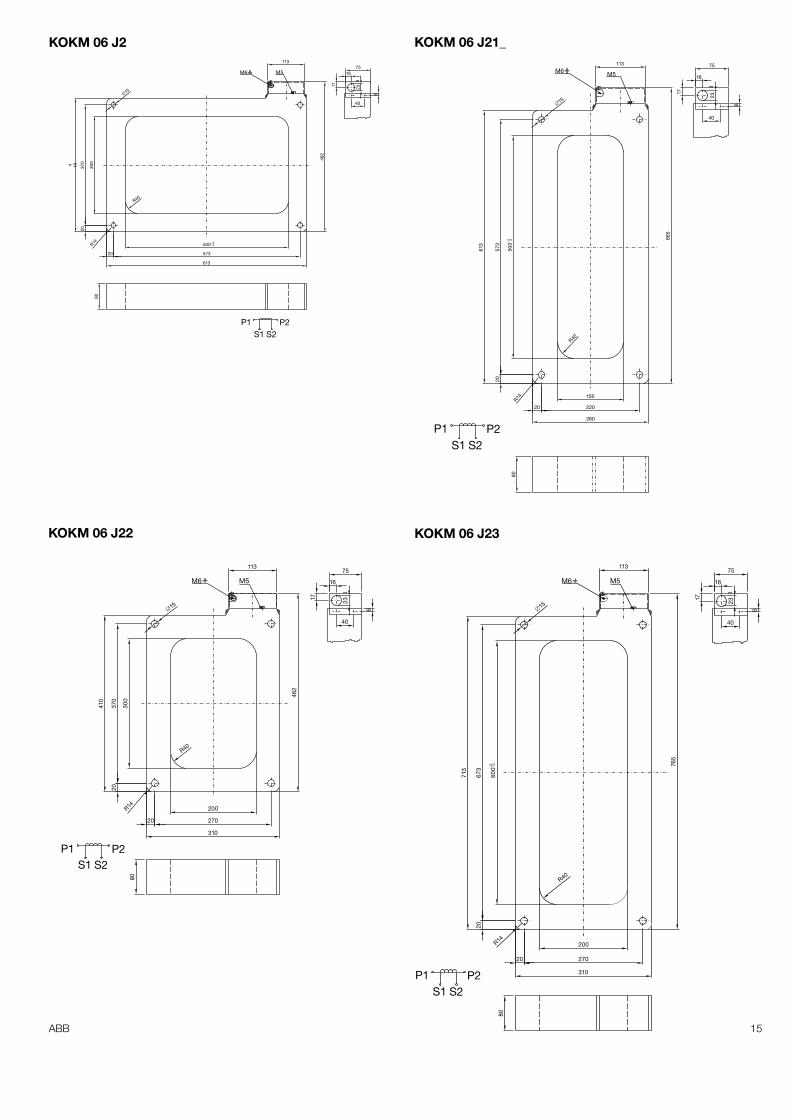
500 0+3
573
613
R40
R14
20
300
3704 10
20
462
80
113
M5M6
�15
75
40
23
16
17
6
S1P1 P2
S2
S2S1P1 P2
M5M6113
80R14
R40
150
220
260
20
500+3 0
573
613
665
�15
20
75
40
23
16
17
6
S1P1 P2
S2
80
113
M5M6
�15
200
270
310
R40
R14
20
300
370
410
20
462
75
40
23
16
17
6
KOKM 06 J2 KOKM 06 J21_
KOKM 06 J22
S1P1 P2
S2
M5M6
80
200
270
310
R14
R40
600
0+3
673
713
20
20
765
113
�15
75
40
23
16
17
6
KOKM 06 J23
16 ABB
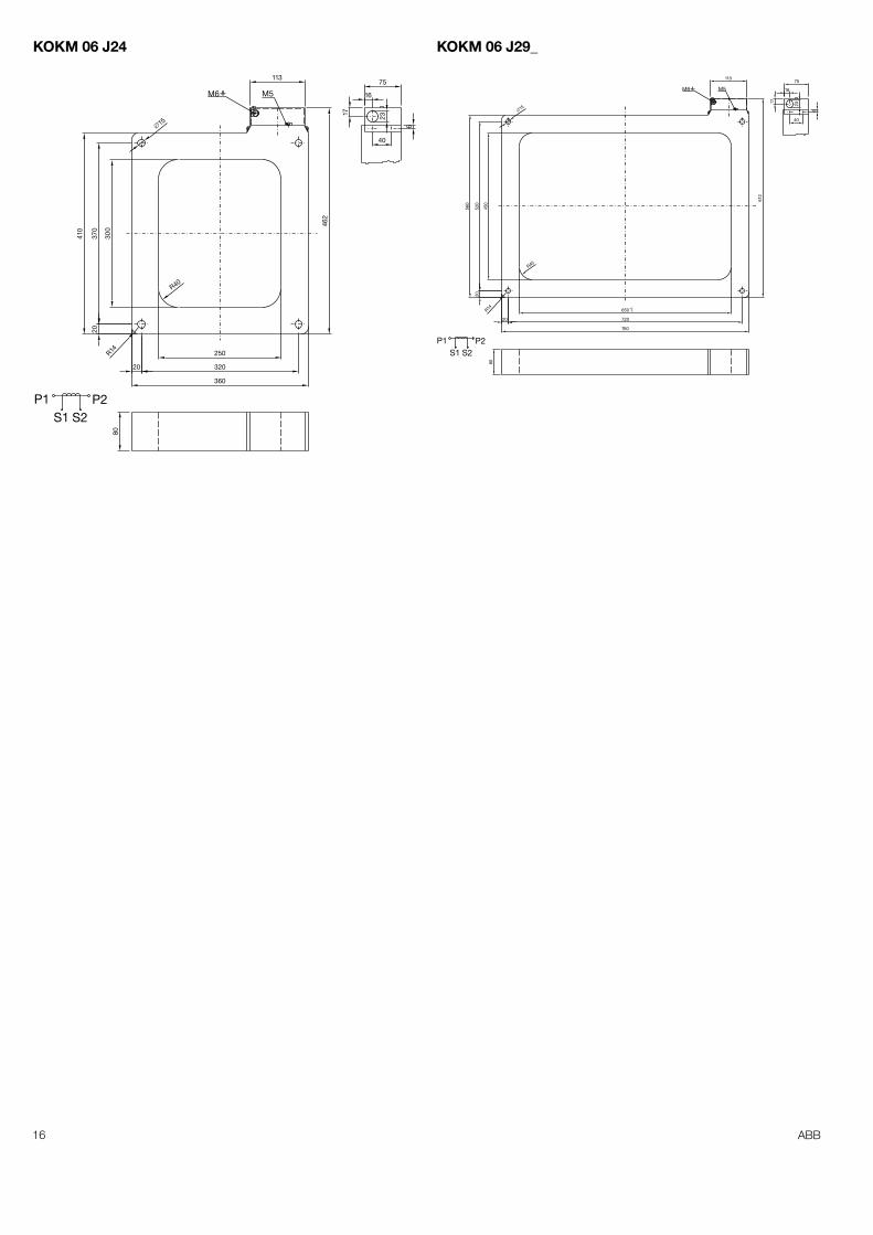
KOKM 06 J24 KOKM 06 J29_
S1P1 P2
S2
80
113
M5M6
�15
250
320
360
R40
R14
20
300
370
410
20
462
75
40
23
16
17
6
S1P1 P2
S2
80
113
M5M6
�15
650
720
760
R40
R14
20
450
520
560
20
612
0+3
17
16
23
40
6
75
17ABB
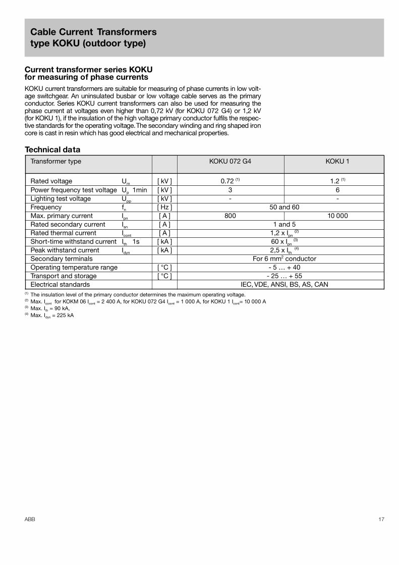
Cable Current Transformerstype KOKU (outdoor type)
Technical dataTransformer type KOKU 072 G4 KOKU 1
Rated voltage Um [ kV ] 0.72 (1) 1.2 (1)
Power frequency test voltage Up 1min [ kV ] 3 6Lighting test voltage Upp [ kV ] - -Frequency fn [ Hz ] 50 and 60Max. primary current Ipn [ A ] 800 10 000Rated secondary current Isn [ A ] 1 and 5Rated thermal current Icont [ A ] 1,2 x Ipn
(2)
Short-time withstand current Ith 1s [ kA ] 60 x Ipn (3)
Peak withstand current Idyn [ kA ] 2,5 x Ith (4)
Secondary terminals For 6 mm2 conductorOperating temperature range [ °C ] - 5 … + 40Transport and storage [ °C ] - 25 … + 55Electrical standards IEC, VDE, ANSI, BS, AS, CAN
(1) The insulation level of the primary conductor determines the maximum operating voltage.(2) Max. Icont for KOKM 06 Icont = 2 400 A, for KOKU 072 G4 Icont = 1 000 A, for KOKU 1 Icont= 10 000 A(3) Max. Ith = 90 kA,(4) Max. Idyn = 225 kA
Current transformer series KOKUfor measuring of phase currentsKOKU current transformers are suitable for measuring of phase currents in low volt-age switchgear. An uninsulated busbar or low voltage cable serves as the primaryconductor. Series KOKU current transformers can also be used for measuring thephase current at voltages even higher than 0,72 kV (for KOKU 072 G4) or 1,2 kV(for KOKU 1), if the insulation of the high voltage primary conductor fulfils the respec-tive standards for the operating voltage. The secondary winding and ring shaped ironcore is cast in resin which has good electrical and mechanical properties.
18 ABB
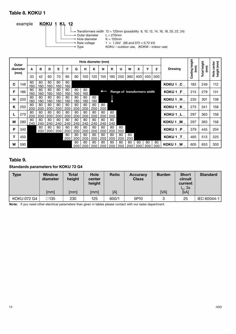
example KOKU 1 KL 12
Transformers width 12 = 120mm (possibility 8, 10, 12, 14, 16, 18, 20, 22, 24)Outer diameter L = 270mmHole diameter K = 120mmRate voltage 1 = 1.2kV (06 and 072 = 0.72 kV)Type KOKU – outdoor use, (KOKM – indoor use)
Outerdiameter
(mm)A B D E F G H K N R U W X Y Z
C
F
H
K
L
M
P
T
W
80160801608018080
20080
20080
240
80160801608018080
20080
20080
24080
200
80160801608018080
20080
20080
24080
200
148
33 42 60 70 85 90 100 120 155 180 250 360 400 450 500
186
200
250
270
280
340
450
590
80160801608018080
20080
2008024080
200
80160801608018080
20080
2008024080
20080
200
801608018080
20080
2008024080
20080
20080
200
801608018080
20080
2008024080
20080
20080
200
8018080
20080
2008024080
20080
20080
200
8020080
2008024080
20080
20080
200
8020080
24080
20080
20080
200
8020080
20080
200
8020080
20080
20080
20080
200
Hole diameter (mm)
Drawing
Cas
ting
heig
ht(m
m)
Tota
l hei
ght
(mm
)
Hol
e ce
nter
heig
ht (m
m)
KOKU 1 _C _
KOKU 1 _F _
KOKU 1 _H _
KOKU 1 _K _
KOKU 1 _L _
KOKU 1 _M _
KOKU 1 _P _
KOKU 1 _T _
KOKU 1 _W _
183
213
235
275
297
297
379
465
605
249
279
301
341
363
363
445
513
653
112
131
138
158
158
158
204
225
300
Range of transformers width
Table 8. KOKU 1
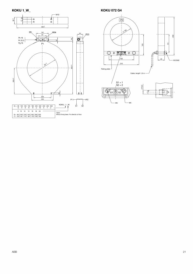
Table 9.Standards parameters for KOKU 72 G4
Type Window Total Hole Ratio Accuracy Burden Short Standarddiameter height center Class circuit
height currentIth, 3s
[mm] [mm] [mm] [A] [VA] [kA]
KOKU 072 G4 ∅ 135 230 125 600/1 5P10 3 25 IEC 60044-1Note: If you need other electrical parameters than given in tables please contact with our sales department.
19ABB
±2
140
52
1140
B
(80)
CB(1
000.
..160
)±2
±2±2
20
1152707518
78
B
(60.
..140
)
80
B
(16
0)
±2
S1 S2
P2P1
+20
±2
±3±2
±2
IP44
16
17
M5 M5
Pr 22,5Pk 16
Pg 16
97142
249
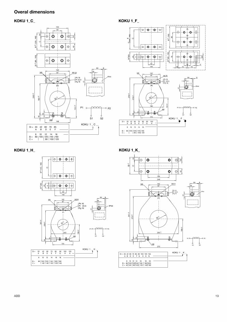
KOKU 1 _ C __
M8
P1
Di = 33 42 60 70 85A B D E F
8 10 12 14 16B = 80 100 120 140 160C = 80 100 120
112
148
Di
14
183
18
1140
52124
C20
B
(12
0...1
60)
B
(80
...10
0)
864
150
1440
20CB
±2
52
1140
B
(80)
±2
C
B
(100
...18
0)±2
±2
P1
S1 S2
P2
P1
+30
P1
131
170
14
18
186
Di
213
±2
±3
864
17
16
97142
279
IP44
M5
Pk 16Pr 22,5PG 16
M5
KOKU 1 _ F __Di = 33 42 60 70 85 90 100
A B D E F G H
8 10 12 14 16
B = 80 100 120 140 160C = 80 100 120
M8
P1
S1
P1 P2
S2M8
Di = 33 42 60 70 85 90 100 120A B D E F G H K
8 10 12 14 16 18
B = 80 100 120 140 160 180C = 60 80 100 120 140
±2
+30
138200
170
14
18
Di
235±
2
301
±3
140
IP44
16
64 8
17
M5M5
Pg 16
Pk 16Pr 22,5
97142
KOKU 1 _ H _
P1
P1
S1
P2
S2M8
Di = 33 42 60 70 85 90 100 120 155A B D E F G H K N
8 10 12 14 16 18 20B = 80 100 120 140 160 180 200C = 40 60 80 100 120 140 160
±2
0-2
+30
158
270
Di
250
15
1827
5±2
341
±3
246
IP44
16
64 817
M6
Pk 16Pr 22,5Pg 16
M597142
KOKU 1 _ K _
KOKU 1_C_ KOKU 1_F_
KOKU 1_H_ KOKU 1_K_
Overal dimensions
20 ABB
150
1440
20CB
±2
150
20CB
±2
1440
P1
P1
S1
P2
S2
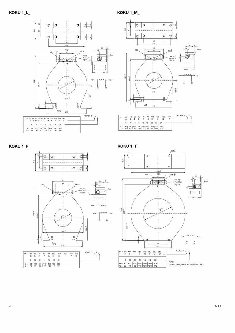
Di = 85 90 100 120 155 180 250 350F G H K N R U W
8 10 12 14 16 18 20
B = 80 100 120 140 160 180 200C = 50 70 90 110 130 150 170
0-3
M8
+40
Note:Without fixing base. Fix directly to floor
180
225
Di
15
225
±3
465
±3513
450
15CB
±1
IP44
17
1664 8
M5M5
Pk 16Pr 22,5Pg 16
97142
KOKU 1 _ T _
P1
P1
S1 S2
P2
M8
Di = 42 60 70 85 90 100 120 155 180 250B D E F G H K N R U
8 10 12 14 16 18 20
B = 80 100 120 140 160 180 200C = 40 60 80 100 120 140 160
±2
+30
0-2
204
270
340
15
1837
9±244
5±3
Di
20CB
±2
1440
.IP44
16
64 8
17
M5 M5
Pr 22,5Pg 16
Pk 16
97
142
KOKU 1 _ P _
Di = 33 42 60 70 85 90 100 120 155 180
B = 80 100 120 140 160 180 200 220 240C = 40 60 80 100 120 140 160 180 200
S1
P2
S2
P1
P1
M8
A B D E F G H K N R
8 10 12 14 16 18 20 22 24
±2
0-2
+30
158
280
270
15
1829
7±236
3±3
Di
246
IP4416
64 8
17
M5
Pg 16
Pk 16Pr 22,5
M597142
KOKU 1 _ M _
P1
P1
S1
P2
S215
8
M8
Di = 33 42 60 70 85 90 100 120 155 180 200A B D E F G H K N R S
8 10 12 14 16 18 20
B = 80 100 120 140 160 180 200C = 40 60 80 100 120 140 160
±2
+30
0-2270
270
Di
15
1829
7±236
3±3
246
IP44
17
16
64 8
Pk 16Pr 22,5Pg 16
M5M6 97142
KOKU 1 _ L _
KOKU 1_L_ KOKU 1_M_
KOKU 1_P_ KOKU 1_T_
21ABB
±3
M12B
25C
0-3590
P1
±3
±3
M5 M5IP23
Di = 90 100 120 155 180 250 350 400 450 500G H K N R U W X Y Z
8 10 12 14 16 18 20
B = 80 100 120 140 160 180 200C = 30 50 70 90 110 130 150
Witout fixing base. Fix directly to floor.Note:
64
200
250
15
605
0+ 4
Di
300
17
48
97
142
Pk 16Pr 22,5Pg 16
P1 P2
S1 S2KOKU _1 _W
S2S1
P2
S1 S2
Cable, length 1,6 m
Rating plate
M5 M5
M12X60
�135
125
150
210
45
111
230
�13
,3
1
S2 = 2
2
S1 = 1
KOKU 1_W_ KOKU 072 G4
22 ABB
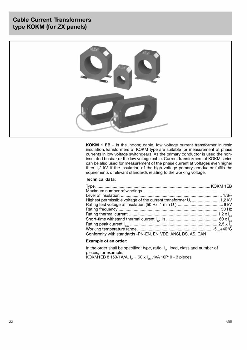
KOKM 1 EB – is the indoor, cable, low voltage current transformer in resininsulation.Transformers of KOKM type are suitable for measurement of phasecurrents in low voltage switchgears. As the primary conductor is used the non-insulated busbar or the low voltage cable. Current transformers of KOKM seriescan be also used for measurement of the phase current at voltages even higherthen 1,2 kV, if the insulation of the high voltage primary conductor fulfils theequirements of elevant standards relating to the working voltage.
Technical data:
Type ................................................................................................... KOKM 1EBMaximum number of windings .......................................................................... 1Level of insulation ....................................................................................... 1/6/-Highest permissible voltage of the current transformer Ur ........................ 1,2 kVRating test voltage of insulation (50 Hz, 1 min Up) ....................................... 6 kVRating frequency ....................................................................................... 50 HzRating thermal current ............................................................................ 1,2 x IpnShort-time withstand thermal current Ith, 1s ............................................. 60 x IpnRating peak current Idyn ........................................................................... 2,5 x IthWorking temperature range ................................................................ -5...+40°CConformity with standards -PN-EN, EN, VDE, ANSI, BS, AS, CAN
Example of an order:
In the order shall be specified: type, ratio, Ith , load, class and number ofpieces, for example:KOKM1EB 8 150/1A/A, Ith = 60 x Ipn ,1VA 10P10 - 3 pieces
Cable Current Transformerstype KOKM (for ZX panels)
23ABB
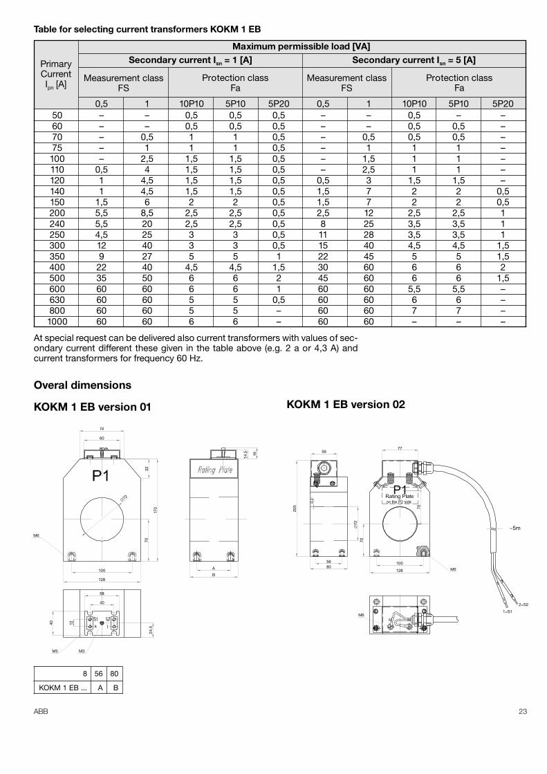
0,5 1 10P10 5P10 5P20 0,5 1 10P10 5P10 5P2050 – – 0,5 0,5 0,5 – – 0,5 – –60 – – 0,5 0,5 0,5 – – 0,5 0,5 –70 – 0,5 1 1 0,5 – 0,5 0,5 0,5 –75 – 1 1 1 0,5 – 1 1 1 –100 – 2,5 1,5 1,5 0,5 – 1,5 1 1 –110 0,5 4 1,5 1,5 0,5 – 2,5 1 1 –120 1 4,5 1,5 1,5 0,5 0,5 3 1,5 1,5 –140 1 4,5 1,5 1,5 0,5 1,5 7 2 2 0,5150 1,5 6 2 2 0,5 1,5 7 2 2 0,5200 5,5 8,5 2,5 2,5 0,5 2,5 12 2,5 2,5 1240 5,5 20 2,5 2,5 0,5 8 25 3,5 3,5 1250 4,5 25 3 3 0,5 11 28 3,5 3,5 1300 12 40 3 3 0,5 15 40 4,5 4,5 1,5350 9 27 5 5 1 22 45 5 5 1,5400 22 40 4,5 4,5 1,5 30 60 6 6 2500 35 50 6 6 2 45 60 6 6 1,5600 60 60 6 6 1 60 60 5,5 5,5 –630 60 60 5 5 0,5 60 60 6 6 –800 60 60 5 5 – 60 60 7 7 –1000 60 60 6 6 – 60 60 – – –
PrimaryCurrentIpn [A]
Measurement classFS
Protection classFa
Measurement classFS
Protection classFa
Secondary current Isn = 1 [A] Secondary current Isn = 5 [A]Maximum permissible load [VA]
At special request can be delivered also current transformers with values of sec-ondary current different these given in the table above (e.g. 2 a or 4,3 A) andcurrent transformers for frequency 60 Hz.
Table for selecting current transformers KOKM 1 EB
74
60
32
170
70
M6
100
128
58
40
40 12
M3M5
24,5
1914,5
A
B
�72
KOKM 1 EB version 01
7756
5680
205
�72
0,5°
70
70
128
100M6
M61=S1
2=S2
~5m
KOKM 1 EB version 02
8 56 80
KOKM 1 EB ... A B
Overal dimensions
24 ABB
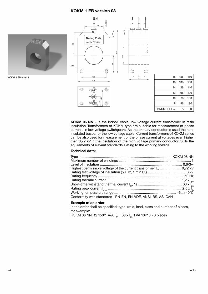
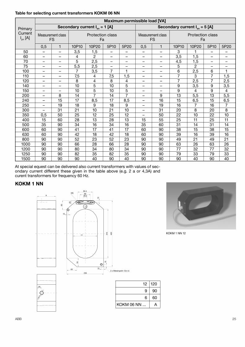
KOKM 06 NN – is the indoor, cable, low voltage current transformer in resininsulation. Transformers of KOKM type are suitable for measurement of phasecurrents in low voltage switchgears. As the primary conductor is used the non-insulated busbar or the low voltage cable. Current transformers of KOKM seriescan be also used for measurement of the phase current at voltages even higherthen 0,72 kV, if the insulation of the high voltage primary conductor fulfils theequirements of elevant standards elating to the working voltage.
Technical data:
Type ............................................................................................... KOKM 06 NNMaximum number of windings .......................................................................... 1Level of insulation .................................................................................... 0,6/3/-Highest permissible voltage of the current transformer Ur ...................... 0,72 kVRating test voltage of insulation (50 Hz, 1 min Up) ....................................... 3 kVRating frequency ....................................................................................... 50 HzRating thermal current ............................................................................ 1,2 x IpnShort-time withstand thermal current Ith, 1s ............................................. 60 x IpnRating peak current Idyn ........................................................................... 2,5 x IthWorking temperature range ................................................................ -5...+40°CConformity with standards - PN-EN, EN, VDE, ANSI, BS, AS, CAN
Example of an order:In the order shall be specified: type, ratio, load, class and number of pieces,for example:KOKM 06 NN; 12 150/1 A/A, Ith = 60 x Ipn,1 VA 10P10 - 3 pieces
18 156 180
16 136 160
14 116 140
12 96 120
10 76 100
8 56 80
KOKM 1 EB ... A B
KOKM 1 EB version 03
ok. 5
000
8
74
32
90
70
170
�72
max
6
M6
100
128
130
9050
3S
2S
1S
0,5°
A
BKOKM 1 EB 8 ver. 1
25ABB
0,5 1 10P10 10P20 5P10 5P20 0,5 1 10P10 10P20 5P10 5P2050 – – 3,5 1,5 – – – – 3 1 – –60 – – 4 2 – – – – 3,5 1,5 – –70 – – 5 2,5 – – – – 4,5 1,5 – –75 – – 5,5 2,5 – – – – 5 2 – –100 – – 7 3,5 7 1 – – 6 2,5 6 1110 – – 7,5 4 7,5 1,5 – – 7 3 7 1,5120 – – 8 4 8 4 – – 7 2,5 7 2,5140 – – 10 5 10 5 – – 9 3,5 9 3,5150 – – 10 5 10 5 – – 9 4 9 4200 – 8 14 7 14 7 – 9 13 5,5 13 5,5240 – 15 17 8,5 17 8,5 – 16 15 6,5 15 6,5250 – 19 18 9 18 9 – 19 16 7 16 7300 – 31 21 10 21 10 – 31 20 8 20 8350 0,5 50 25 12 25 12 – 50 22 10 22 10400 15 60 28 13 28 13 15 55 25 11 25 11500 35 90 34 16 34 16 35 60 31 14 31 14600 60 90 41 17 41 17 60 90 38 15 38 15630 60 90 42 18 42 18 60 90 39 16 39 16800 90 90 52 23 52 23 90 90 49 21 49 211000 90 90 66 28 66 28 90 90 63 26 63 261200 90 90 80 34 80 34 90 90 77 32 77 321250 90 90 82 35 82 35 90 90 79 33 79 331500 90 90 90 40 90 40 90 90 90 40 90 40
PrimaryCurrentIpn [A]
Measurement classFS
Protection classFa
Measurement classFS
Protection classFa
Secondary current Isn = 1 [A] Secondary current Isn = 5 [A]Maximum permissible load [VA]
At special equest can be delivered also current transformers with values of sec-ondary current different these given in the table above (e.g. 2 a or 4,3A) andcurent transformers for frequency 60 Hz.
Table for selecting current transformers KOKM 06 NN
A
95.569
26.5M5
60
13
22
10
420
310
15
152 x Messingrohr 12x1,5
55
65
235
30
∅20
.5
KOKM 1 NN
12 120
9 90
6 60
KOKM 06 NN ... A
KOKM 1 NN 12
26 ABB
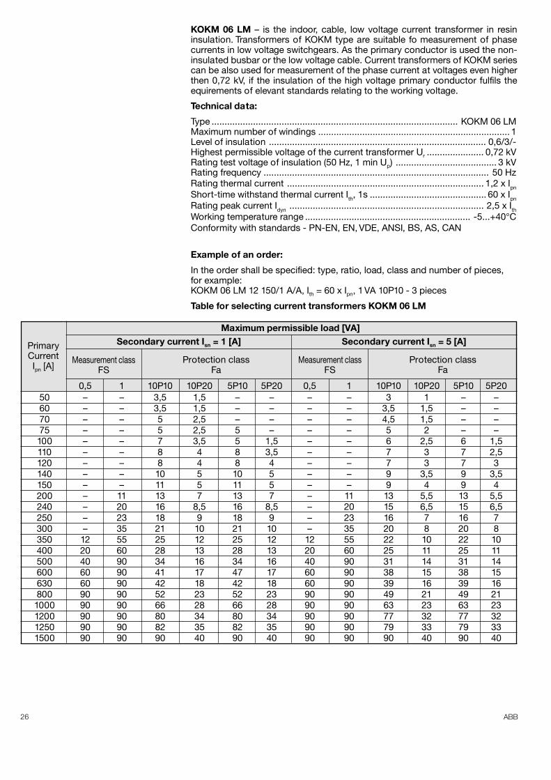
KOKM 06 LM – is the indoor, cable, low voltage current transformer in resininsulation. Transformers of KOKM type are suitable fo measurement of phasecurrents in low voltage switchgears. As the primary conductor is used the non-insulated busbar or the low voltage cable. Current transformers of KOKM seriescan be also used for measurement of the phase current at voltages even higherthen 0,72 kV, if the insulation of the high voltage primary conductor fulfils theequirements of elevant standards relating to the working voltage.
Technical data:
Type ............................................................................................... KOKM 06 LMMaximum number of windings .......................................................................... 1Level of insulation .................................................................................... 0,6/3/-Highest permissible voltage of the current transformer Ur ...................... 0,72 kVRating test voltage of insulation (50 Hz, 1 min Up) ....................................... 3 kVRating frequency ....................................................................................... 50 HzRating thermal current ............................................................................ 1,2 x IpnShort-time withstand thermal current Ith, 1s ............................................. 60 x IpnRating peak current Idyn ........................................................................... 2,5 x IthWorking temperature range ................................................................ -5...+40°CConformity with standards - PN-EN, EN, VDE, ANSI, BS, AS, CAN
Example of an order:
In the order shall be specified: type, ratio, load, class and number of pieces,for example:KOKM 06 LM 12 150/1 A/A, Ith = 60 x Ipn, 1 VA 10P10 - 3 pieces
Table for selecting current transformers KOKM 06 LM
0,5 1 10P10 10P20 5P10 5P20 0,5 1 10P10 10P20 5P10 5P2050 – – 3,5 1,5 – – – – 3 1 – –60 – – 3,5 1,5 – – – – 3,5 1,5 – –70 – – 5 2,5 – – – – 4,5 1,5 – –75 – – 5 2,5 5 – – – 5 2 – –100 – – 7 3,5 5 1,5 – – 6 2,5 6 1,5110 – – 8 4 8 3,5 – – 7 3 7 2,5120 – – 8 4 8 4 – – 7 3 7 3140 – – 10 5 10 5 – – 9 3,5 9 3,5150 – – 11 5 11 5 – – 9 4 9 4200 – 11 13 7 13 7 – 11 13 5,5 13 5,5240 – 20 16 8,5 16 8,5 – 20 15 6,5 15 6,5250 – 23 18 9 18 9 – 23 16 7 16 7300 – 35 21 10 21 10 – 35 20 8 20 8350 12 55 25 12 25 12 12 55 22 10 22 10400 20 60 28 13 28 13 20 60 25 11 25 11500 40 90 34 16 34 16 40 90 31 14 31 14600 60 90 41 17 47 17 60 90 38 15 38 15630 60 90 42 18 42 18 60 90 39 16 39 16800 90 90 52 23 52 23 90 90 49 21 49 211000 90 90 66 28 66 28 90 90 63 23 63 231200 90 90 80 34 80 34 90 90 77 32 77 321250 90 90 82 35 82 35 90 90 79 33 79 331500 90 90 90 40 90 40 90 90 90 40 90 40
PrimaryCurrentIpn [A]
Measurement classFS
Protection classFa
Measurement classFS
Protection classFa
Secondary current Isn = 1 [A] Secondary current Isn = 5 [A]Maximum permissible load [VA]
27ABB
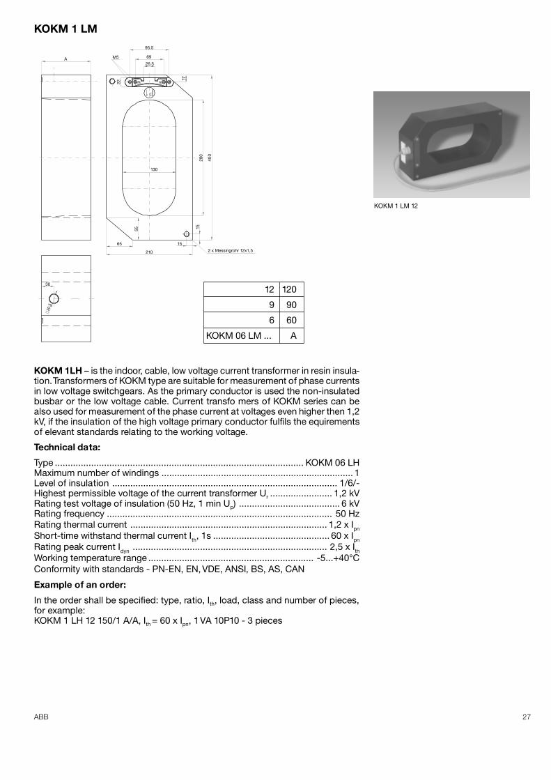
KOKM 1 LM
A M5
95.5
69
26.5
17
22
400
280
130
55
65
30
210
15
15
2 x Messingrohr 12x1,5
∅20
.5
12 120
9 90
6 60
KOKM 06 LM ... A
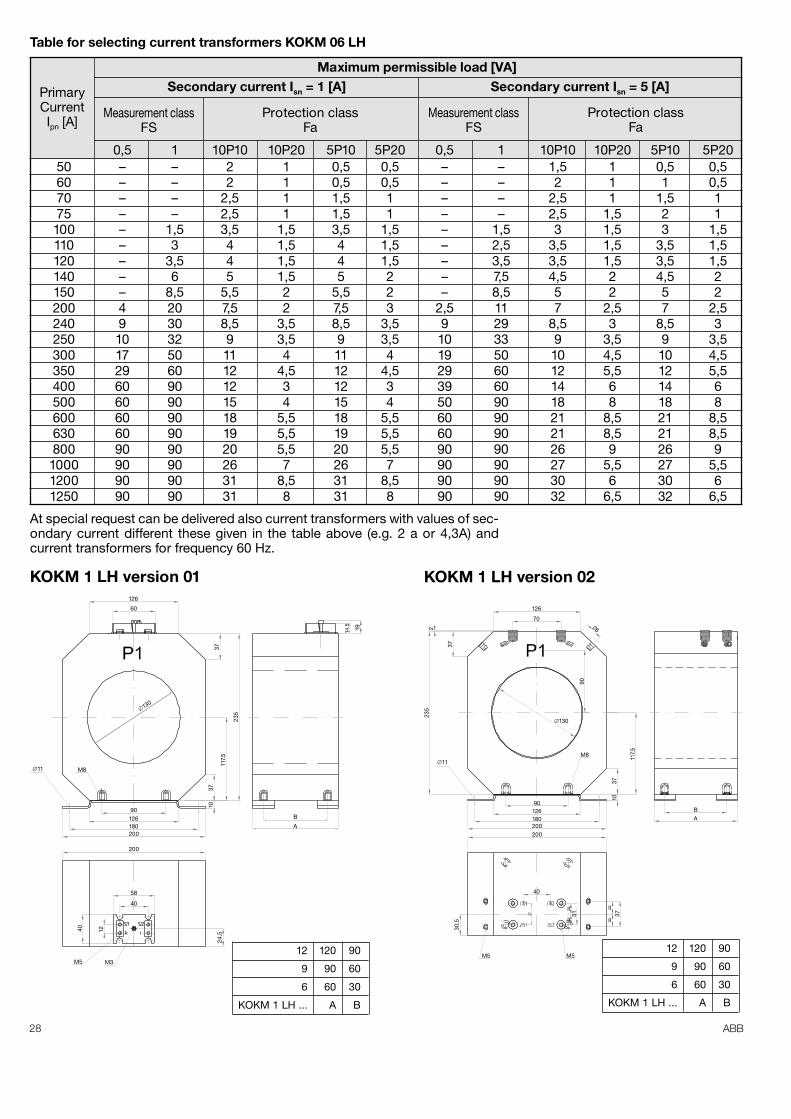
KOKM 1LH – is the indoor, cable, low voltage current transformer in resin insula-tion. Transformers of KOKM type are suitable for measurement of phase currentsin low voltage switchgears. As the primary conductor is used the non-insulatedbusbar or the low voltage cable. Current transfo mers of KOKM series can bealso used for measurement of the phase current at voltages even higher then 1,2kV, if the insulation of the high voltage primary conductor fulfils the equirementsof elevant standards relating to the working voltage.
Technical data:
Type ................................................................................................ KOKM 06 LHMaximum number of windings .......................................................................... 1Level of insulation ....................................................................................... 1/6/-Highest permissible voltage of the current transformer Ur ........................ 1,2 kVRating test voltage of insulation (50 Hz, 1 min Up) ....................................... 6 kVRating frequency ....................................................................................... 50 HzRating thermal current ............................................................................ 1,2 x IpnShort-time withstand thermal current Ith, 1s ............................................. 60 x IpnRating peak current Idyn ........................................................................... 2,5 x IthWorking temperature range ................................................................ -5...+40°CConformity with standards - PN-EN, EN, VDE, ANSI, BS, AS, CAN
Example of an order:
In the order shall be specified: type, ratio, Ith, load, class and number of pieces,for example:KOKM 1 LH 12 150/1 A/A, Ith = 60 x Ipn, 1 VA 10P10 - 3 pieces
KOKM 1 LM 12
28 ABB
0,5 1 10P10 10P20 5P10 5P20 0,5 1 10P10 10P20 5P10 5P2050 – – 2 1 0,5 0,5 – – 1,5 1 0,5 0,560 – – 2 1 0,5 0,5 – – 2 1 1 0,570 – – 2,5 1 1,5 1 – – 2,5 1 1,5 175 – – 2,5 1 1,5 1 – – 2,5 1,5 2 1100 – 1,5 3,5 1,5 3,5 1,5 – 1,5 3 1,5 3 1,5110 – 3 4 1,5 4 1,5 – 2,5 3,5 1,5 3,5 1,5120 – 3,5 4 1,5 4 1,5 – 3,5 3,5 1,5 3,5 1,5140 – 6 5 1,5 5 2 – 7,5 4,5 2 4,5 2150 – 8,5 5,5 2 5,5 2 – 8,5 5 2 5 2200 4 20 7,5 2 7,5 3 2,5 11 7 2,5 7 2,5240 9 30 8,5 3,5 8,5 3,5 9 29 8,5 3 8,5 3250 10 32 9 3,5 9 3,5 10 33 9 3,5 9 3,5300 17 50 11 4 11 4 19 50 10 4,5 10 4,5350 29 60 12 4,5 12 4,5 29 60 12 5,5 12 5,5400 60 90 12 3 12 3 39 60 14 6 14 6500 60 90 15 4 15 4 50 90 18 8 18 8600 60 90 18 5,5 18 5,5 60 90 21 8,5 21 8,5630 60 90 19 5,5 19 5,5 60 90 21 8,5 21 8,5800 90 90 20 5,5 20 5,5 90 90 26 9 26 91000 90 90 26 7 26 7 90 90 27 5,5 27 5,51200 90 90 31 8,5 31 8,5 90 90 30 6 30 61250 90 90 31 8 31 8 90 90 32 6,5 32 6,5
PrimaryCurrentIpn [A]
Measurement classFS
Protection classFa
Measurement classFS
Protection classFa
Secondary current Isn = 1 [A] Secondary current Isn = 5 [A]Maximum permissible load [VA]
At special request can be delivered also current transformers with values of sec-ondary current different these given in the table above (e.g. 2 a or 4,3A) andcurrent transformers for frequency 60 Hz.
Table for selecting current transformers KOKM 06 LH
126
60
37
235
117.
5
3710
200
20018012690
M8�11
B
A
1914.5
58
40
24,5
40 12
M3M5
�130
KOKM 1 LH version 01
12 120 90
9 90 60
6 60 30
KOKM 1 LH ... A B
126
70
37
2 26
90
235
117,
5
3710
M8�11
�130
BA
90126180200200
37
II
II
II
II
31
40
M5M5
30,5
KOKM 1 LH version 02
12 120 90
9 90 60
6 60 30
KOKM 1 LH ... A B
29ABB
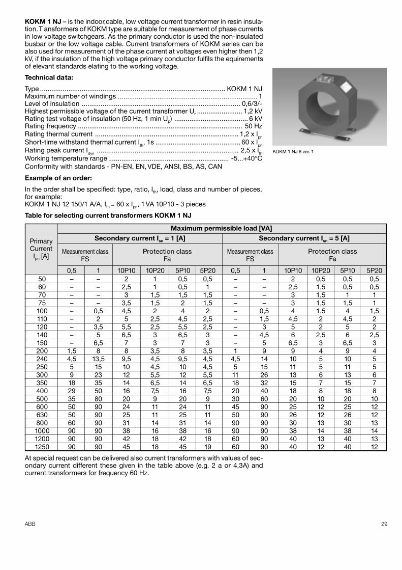
KOKM 1 NJ – is the indoor,cable, low voltage current transformer in resin insula-tion. T ansformers of KOKM type are suitable for measurement of phase currentsin low voltage switchgears. As the primary conductor is used the non-insulatedbusbar or the low voltage cable. Current transformers of KOKM series can bealso used for measurement of the phase current at voltages even higher then 1,2kV, if the insulation of the high voltage primary conductor fulfils the equirementsof elevant standards elating to the working voltage.
Technical data:
Type .................................................................................................. KOKM 1 NJMaximum number of windings .......................................................................... 1Level of insulation .................................................................................... 0,6/3/-Highest permissible voltage of the current transformer Ur ........................ 1,2 kVRating test voltage of insulation (50 Hz, 1 min Up) ....................................... 6 kVRating frequency ....................................................................................... 50 HzRating thermal current ............................................................................ 1,2 x IpnShort-time withstand thermal current Ith, 1s ............................................. 60 x IpnRating peak current Idyn ........................................................................... 2,5 x IthWorking temperature range ................................................................ -5...+40°CConformity with standards - PN-EN, EN, VDE, ANSI, BS, AS, CAN
Example of an order:
In the order shall be specified: type, ratio, Ith, load, class and number of pieces,for example:KOKM 1 NJ 12 150/1 A/A, Ith = 60 x Ipn, 1 VA 10P10 - 3 pieces
Table for selecting current transformers KOKM 1 NJ
0,5 1 10P10 10P20 5P10 5P20 0,5 1 10P10 10P20 5P10 5P2050 – – 2 1 0,5 0,5 – – 2 0,5 0,5 0,560 – – 2,5 1 0,5 1 – – 2,5 1,5 0,5 0,570 – – 3 1,5 1,5 1,5 – – 3 1,5 1 175 – – 3,5 1,5 2 1,5 – – 3 1,5 1,5 1100 – 0,5 4,5 2 4 2 – 0,5 4 1,5 4 1,5110 – 2 5 2,5 4,5 2,5 – 1,5 4,5 2 4,5 2120 – 3,5 5,5 2,5 5,5 2,5 – 3 5 2 5 2140 – 5 6,5 3 6,5 3 – 4,5 6 2,5 6 2,5150 – 6,5 7 3 7 3 – 5 6,5 3 6,5 3200 1,5 8 8 3,5 8 3,5 1 9 9 4 9 4240 4,5 13,5 9,5 4,5 9,5 4,5 4,5 14 10 5 10 5250 5 15 10 4,5 10 4,5 5 15 11 5 11 5300 9 23 12 5,5 12 5,5 11 26 13 6 13 6350 18 35 14 6,5 14 6,5 18 32 15 7 15 7400 29 50 16 7,5 16 7,5 20 40 18 8 18 8500 35 80 20 9 20 9 30 60 20 10 20 10600 50 90 24 11 24 11 45 90 25 12 25 12630 50 90 25 11 25 11 50 90 26 12 26 12800 60 90 31 14 31 14 90 90 30 13 30 131000 90 90 38 16 38 16 90 90 38 14 38 141200 90 90 42 18 42 18 60 90 40 13 40 131250 90 90 45 18 45 19 60 90 40 12 40 12
PrimaryCurrentIpn [A]
Measurement classFS
Protection classFa
Measurement classFS
Protection classFa
Secondary current Isn = 1 [A] Secondary current Isn = 5 [A]Maximum permissible load [VA]
At special request can be delivered also current transformers with values of sec-ondary current different these given in the table above (e.g. 2 a or 4,3A) andcurrent transformers for frequency 60 Hz.
KOKM 1 NJ 8 ver. 1
30 ABB
74
8
32
ok 5
000
max
6
70
�72
170
0,5°
90
120
148
M6
A
B
130
9050
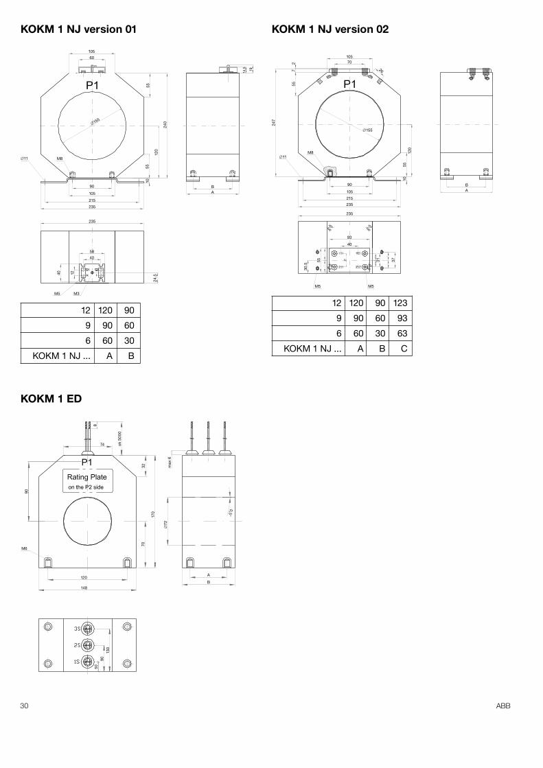
KOKM 1 ED
10570
26
�155
27
55
247
M8�11
5512
010
90
105
215
235
235
93
40
55
30.5
3731
M5 M5
AB
KOKM 1 NJ version 02
12 120 90 123
9 90 60 93
6 60 30 63
KOKM 1 NJ ... A B C
105
60
55
240
120
5510
�155
90
105
215
235
M8�11
235
24.540 12
58
40
M3M5
1914.5
BA
KOKM 1 NJ version 01
12 120 90
9 90 60
6 60 30
KOKM 1 NJ ... A B
31ABB
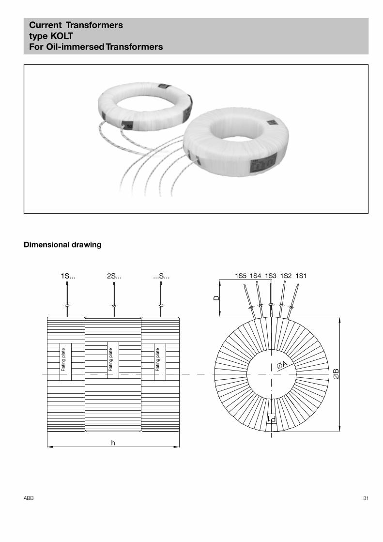
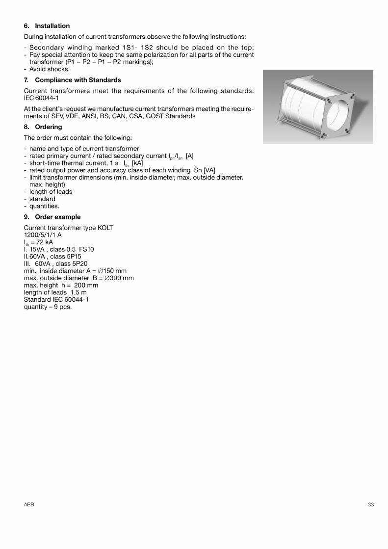
Current Transformerstype KOLTFor Oil-immersed Transformers
Dimensional drawing
1S... 2S... ...S...
D
1S5 1S4 1S3 1S2 1S1
�B
�A
h
Rat
ing
plat
e
Rat
ing
plat
e
Rat
ing
plat
e
P1
32 ABB
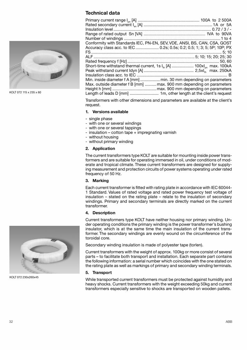
Technical dataPrimary current range Ipn [A] ..................................................... 100A to 2 500ARated secondary current Isn [A] ........................................................... 1A or 5AInsulation level .................................................................................... 0.72 / 3 / -Range of rated output Sn [VA] ..................................................... 1VA to 90VANumber of windings ................................................................................... 1 to 4Conformity with Standards IEC, PN-EN, SEV, VDE, ANSI, BS, CAN, CSA, GOSTAccuracy class acc. to IEC .................... 0.2s; 0.5s; 0.2; 0.5; 1; 3; 5; 5P; 10P; PXFS ................................................................................................................ 5; 10ALF ....................................................................................... 5; 10; 15; 20; 25; 30Rated frequency f [Hz] ............................................................................... 50, 60Short-time withstand thermal current, 1s Ith [A] ................... 100xIpn max. 100kAPeak withstand current Idyn [A] ........................................... 2,5xIth max. 250kAInsulation class acc. to IEC .............................................................................. BMin. inside diameter f A [mm] ................. min. 30 mm depending on parametersMax. outside diameter f B [mm] ..........max. 900 mm depending on parametersHeight h [mm] ......................................max. 900 mm depending on parametersLength of leads D [mm] ......................... 1m, other length at the client’s request
Transformers with other dimensions and parameters are available at the client’srequest.
1. Versions available
- single phase- with one or several windings- with one or several tappings- insulation – cotton tape + impregnating varnish- without housing- without primary winding
2. Application
The current transformers type KOLT are suitable for mounting inside power trans-formers and are suitable for operating immersed in oil, under conditions of mod-erate and tropical climate. These current transformers are designed for supply-ing measurement and protection circuits of power systems operating under ratedfrequency of 50 Hz.
3. Marking
Each current transformer is fitted with rating plate in accordance with IEC 60044-1 Standard. Values of rated voltage and rated power frequency test voltage ofinsulation – stated on the rating plate – relate to the insulation of secondarywindings. Primary and secondary terminals are directly marked on the currenttransformer.
4. Description
Current transformers type KOLT have neither housing nor primary winding. Un-der operating conditions the primary winding is the power transformer’s bushinginsulator, which is at the same time the main insulation of the current trans-former. The secondary windings are evenly wound on the circumference of thetoroidal core.
Secondary winding insulation is made of polyester tape (torlen).
Current transformers with the weight of approx. 100kg or more consist of severalparts – to facilitate both transport and installation. Each separate part containsthe following information: a serial number which coincides with the one stated onthe rating plate as well as markings of primary and secondary winding terminals.
5. Transport
While transported current transformers must be protected against humidity andheavy shocks. Current transformers with the weight exceeding 50kg and currenttransformers especially sensitive to shocks are transported on wooden pallets.
KOLT 072 115 x 235 x 60
KOLT 072 230x260x45
33ABB
6. Installation
During installation of current transformers observe the following instructions:
- Secondary winding marked 1S1- 1S2 should be placed on the top;- Pay special attention to keep the same polarization for all parts of the current
transformer (P1 – P2 – P1 – P2 markings); .- Avoid shocks.
7. Compliance with Standards
Current transformers meet the requirements of the following standards:IEC 60044-1
At the client’s request we manufacture current transformers meeting the require-ments of SEV, VDE, ANSI, BS, CAN, CSA, GOST Standards
8. Ordering
The order must contain the following:
- name and type of current transformer- rated primary current / rated secondary current Ipn/Isn [A]- short-time thermal current, 1 s Ith [kA]- rated output power and accuracy class of each winding Sn [VA]- limit transformer dimensions (min. inside diameter, max. outside diameter,
max. height)- length of leads- standard- quantities.
9. Order example
Current transformer type KOLT1200/5/1/1 AIth = 72 kAI. 15VA , class 0.5 FS10II.60VA , class 5P15III. 60VA , class 5P20min. inside diameter A = ∅150 mmmax. outside diameter B = ∅300 mmmax. height h = 200 mmlength of leads 1,5 mStandard IEC 60044-1quantity – 9 pcs.

34 ABB
Note

35ABB

ABB Sp. z o.o.Power Technologies Divisionul. Leszno 5906-300 Przasnysz, PolandPhone: (+48 22) 52 52 838, 51 52 831
(+48 29) 75 33 223, 75 33 240Fax: +48 22 51 52 659, +48 29 75 33 327
www.abb.com