cable support in longwall gate roads · cable support in longwall gate roads ... cable bolting was...
TRANSCRIPT

165
CABLE SUPPORT IN LONGWALL GATE ROADS
By Dennis R. Dolinar1 and Lewis A. Martin2
ABSTRACT
Cable bolt technology used by the U.S. coal industry was developed to a large extent in the 1990s. Today,these cable systems include both cable bolts and cable trusses to provide supplemental and secondary supportin gate roads. This cable technology is significantly different than the cable systems in use in either U.S. hard-rock mines or Australian coal mines. Development of this technology was initiated and spurred by researchefforts of the U.S. Bureau of Mines, and has continued under the health and safety programs of the NationalInstitute for Occupational Safety and Health (NIOSH). It was also followed up by work of roof supportmanufacturers to create an essentially new support system. In this paper, the important support characteristicsof both cable bolts and cable trusses are discussed. The design of cable systems and the basis for that designfor tailgate and headgate situations are reviewed and explained. Case histories are presented on the applicationof these support systems based on experience gained at a number of in situ test sites.
1Mining engineer, Pittsburgh Research Laboratory, National Institute for Occupational Safety and Health, Pittsburgh, PA. 2Mechanical engineer, Spokane Research Laboratory, National Institute for Occupational Safety and Health, Spokane, WA.

166
INTRODUCTION
Cable bolting was introduced into the U.S. coal industry in1992 through the research efforts of the U.S. Bureau of Mines.This original work was conducted at a longwall operation inwestern Colorado for the purpose of finding alternative secondarytailgate support [Tadolini and Koch 1993]. For the initial test,cable design and installation were based on cable technologydeveloped for the hard-rock mine industry [Goris et al. 1993;Goris 1990; Goris 1991; Goris et al. 1994]. This involved theinstallation of the cables by hand and using a fully grouted cablewith a pumpable grout system. This technology was certainlyadequate for the hard-rock industry, but not for a high-productionlongwall. Initially, a crew could install 8 to 12 cables per shift,but with experience this number increased to 30 cables per shift.
From this beginning, the cable bolt system used todayquickly evolved until an essentially new product was created.The result was a headed cable bolt installed by machine andanchored with a resin grout cartridge and a partial grout column[McDonnell et al. 1995]. Furthermore, resin manufacturersdeveloped special resins for cable bolt anchors. With these newcable bolt systems, it is now possible to install up to 70 or morecables per shift with a double-boom bolter.
A driving force behind the development and use of cablebolts as secondary support in the tailgate was to replace woodcribs. Wood cribs, especially in the West, were becomingexpensive because of a shortage of timber and a lessening oftimber quality. A typical longwall gate road in the Westsupported by wood cribs requires about 248 acres of timber[Tadolini and Koch 1993]. Cutting this amount of timber hasan environmental impact. The installation of wood cribs islabor intensive and materials handling is a significant problem,not only from a logistic consideration, but also from an injurystandpoint. Especially in the West, where seam are high, alarge number of injuries result from crib installation. The highdensity of the wood cribs necessary in a gate road restrictsventilation and impedes the use of the tailgate as an escapeway[Kadnuck 1994]. All of these considerations can put constraintson the development of super longwall systems.
From a ground control standpoint, wood cribs are far fromideal. Four-point wood cribs are regarded as a soft supportsystem. Improperly built cribs can result in a wide variation inthe performance of individual cribs, thus exacerbating groundconditions. In many western mines, yield pillars are used, andby design the tailgate will be subjected to large amounts ofdeformation, much of which is the result of roof-to-floorconvergence. Yet crib systems will resist this deformation,
taking up a large portion of crib capacity. Wood cribs also haveproblems handling the large lateral movements associated withyield pillar designs.
Today, cable bolts are competing against other newlydeveloped types of standing support developed to replace thewood cribs [Barczak et al. 1996; Mucho et al. 1999]. Thesenew systems are definite improvements over wood cribs. Still,from a ground control standpoint these standing supportsystems use a significant portion of their capacity to resist mainroof-to-floor convergence and limit full access by equipment tothe face.
Cable bolts are used not only as tailgate support but also forsupport in bleeders [Tadolini et al. 1993; McDonnell et al.1995]. They are used as supplemental support, not only inlongwall operations, but also in room-and-pillar mines. Thereare also efforts to adapt cable bolts as primary support becausethey can be installed so they are much longer than the height ofthe opening, a factor that could improve roof support in thin-seam mines. Some consideration is also being given to usinga single-pass system in gate roads, where the cable bolts will beused both as the primary support for development and second-ary support when the panel is mined.
The Australians had used cable bolts in their coal mines asboth supplemental and secondary support [Gale 1987; Gale etal. 1987]. The cables were normally 10 m (33 ft) long, fullygrouted, and installed with a pumpable grout system. Becausethe Australians used a two-entry system with large abutmentpillars and 60 to 120 m (200 to 400 ft ) between entries, thedesign and use of their cable system offered little that could beadapted to use in a U.S. longwall tailgate.
The development of cable bolts also spurred the de-velopment and use of cable trusses. Cable slings had been usedon a limited basis since the 1970s [Mangelsdorf 1982; Scott1989]. However, anchoring the cables was a problem until asystem was devised that used anchorage systems based on aresin cartridge inserted into the drill hole. These truss systemscan be installed with the assistance of a roof bolting machine,though installation can still be accomplished in the traditionalmanner with small drills. Cable trusses are now used as sup-plemental support in headgate entries, especially where hori-zontal stress causes damage. Cable trusses have been used inopen entry recovery rooms and to a limited extent, as secondarysupport in tailgates.
This paper will discuss cable bolts and trusses and the designof cable systems for the support of longwall gate road entries.
CABLE BOLT
Cable bolts are made from a high-strength steel cable. Themost common cable used is seven strands 1.52 to 1.59 cm (0.6to 0.625 in) in diameter (Goris et al. 1994; McDonnell et al.1995). The cable consists of six outer strands wrapped around
a middle or king wire strand (figure 1). The cross-sectionalarea of the steel for the cable is 0.55 cm2 (0.217 in2). Cablebolts can be of any length, but typically range from 2.4 to 6.1 m(8 to 20 ft) for use in a coal mine. The cables bolts are

167
Figure 1.–Seven strand steel cable used to make cable bolts.
Figure 2.–Cable bolt and cable bolt components.
anchored in the roof with resin grout cartridges using only apartial grout column. This leaves a free cable length in thelower portion of the hole. Cable diameters range from 1.27 to2.29 cm (0.5 to 0.9 in), but only the properties of the 1.52-cm(0.6-in) in diameter cable bolts will be discussed in thefollowing sections.
Figure 2 shows the components of a typical cable bolt. Acable bolt consists of a cable head that ties the cable strandstogether and allows the bolt to be installed and rotated with aroof bolter. For ground control, the head is necessary for theungrouted portion of the cable to take load and resist rockmovement. The head also permits the installation of bearingplates and other surface control devices. A barrel-and-wedgesystem is used to attach the head on the cable.
A stiffener is necessary to install the cable bolt and insert itthrough the resin cartridge with a roof bolter. Without thestiffener, the cable is too flexible to be pushed through the resincartridge and will bend outside the hole. If possible, thestiffener should be long enough to be in the hole before thecartridge is punctured by the cable and yet short enough to beinstalled at a given mining height. A stiffener that is as long asthe resin cartridge will allow this to occur. Another function ofthe stiffener is to prevent the cable from being nicked by thebearing plate during installation, which reduces the potential forcorrosion of the cable.
To assist in anchoring the cables and mixing the resin,anchor buttons, "birdcages," nut cases, or bulbs are used in theupper or anchor portion of the cable. These systems are de-signed for specific hole diameters, usually for holes 2.5 to 3.5cm (1 to 1-3/8-in) in diameter. An end button holds the cableend together and assists in inserting the cable through the resin.
A resin keeper or dam keeps the resin confined along the sec-tion of cable to be anchored and also compresses it. The neces-sity of the resin keeper will depend on resin viscosity, holediameter, and cable bolt design.
Other designs allow the cables to be tensioned. This isusually done at the head of the bolt through the wedge-and-barrel-head or by a threaded bar attached to the end of the cable.Tensioning the head and wedge is done by hand while thethreaded rebar can be tensioned by the roof bolter. Cables withyieldable heads are available where large roof deformation isexpected, and loads will exceed cable strength [Tadolini andMcDonnell 1998; Vandekraats et al. 1996].

168
Figure 3.–Cable bolt system installed in a tailgate.
Figure 4.–Load-deformation curve from a laboratorytensile test of a cable.
Figure 5.–Load-deformation curve from a pull test of a cablebolt underground.
CABLE SYSTEM CHARACTERISTICS
The cable system consists of a cable bolt with a ungroutedor free length of cable and a resin grout anchor. The bearingplate and other surface control devices held in place by thecable bolt are also part of the system. The performance of thecable support will depend on how well these components acttogether as a system. Figure 3 shows a cable system installedin a tailgate. In general, the cable should be the weakest part ofthe system where the other components should be designed toreach the ultimate strength of the cable. This includes the head,anchor, and bearing plate. An exception is the speciallydesigned cable head that allow for controlled yield below cablecapacity.
CABLE BOLT CAPACITY
Cable ultimate strength will usually be between 244.7 and266.6 kN (55,000 and 60,000 lbf) and will normally exceed 260kN (58,600 lbf), while elongation of the cable at failure can rangefrom 3.5% to 8%. Cables will begin to yield at about 1% strain.Figure 4 shows a typical test for a cable conducted in thelaboratory where ultimate strength exceeded 260 kN (58,600 lbf).The load deformation curve from an underground pull test of aresin-anchored cable bolt is shown in figure 5. In this pull test,the cable length was 0.3 m (10 ft) and the grout anchor 0.9 m (3ft). A maximum load of 268.7 kN (30.2 tons) was achieved withthe cable failing during the test, indicating that the anchorageexceeded cable strength. In this case, two strands were broken onthe cable, which is typical failure for a cable. When a cablebreaks, there is a sudden, drop in load, often to near zero. This isthen followed by some load recovery, but this is limited by thestrength of the remaining strands and can be highly variable. Theload will drop again when the remaining intact strands begin tobreak. Essentially, the final residual strength of the cable will bezero although the cable will have some intermediate residualstrength. From pull tests, the elongation at failure is usually lessthan 4% strain [Barczak et al. 1996].
CABLE SYSTEM STIFFNESS
The stiffness of a cable bolt will be determined by the freecable length in the hole and the elongation properties of thecable. However, elongation in the resin-anchored section of thecable will influence stiffness and must also be considered. Thedeformation properties of a cable consist of three components-aconstruction, elastic, and rotational elongation. Constructionstiffness is permanent but is usually small. The rotational com-ponent is due to the rotation of the cable about the axis duringa test or as the cable is loaded. The elastic component isdependent in part on the elastic modulus of the steel composingthe cable. The elastic modulus of the steel is 203.4 GPa (29.5million lbf/in2). However, the elastic modulus of the cable is

169
also dependent on the construction of the cable, which involvesthe lay length. The lay length is the distance one strand takesto make a complete revolution around the cable [Maryland andAmerican Iron 1985]. The stiffness can be calculated from thefollowing equations.
K ' E x A /(L) (1)
where K ' stiffness, kN/cm (lbf /in),
A ' area of cable, cm2 (in 2 ),
L ' free cable length, cm (in),
and E ' elastic modulus of the cable, GPa (lbf/in2 ).
Knowing the elastic modulus, length, and area, the cablestiffness can be calculated for a given load. Cable stiffness hasbeen measured underground using a pull test on cables installedin a limestone roof [Zelanko et al. 1995]. For a 3-m-(10-ft-long) cable bolt with a 1.5-m (5-ft) resin anchor and thereforea 1.5-m (5-ft) free length of cable, the initial cable stiffnessbelow the system yield was 106 kN/cm (30.4 tons/in) for cablesinstalled in a 2.5-cm (1-in) in diameter hole, and 98 kN/cm (28tons/in) for a cable installed in 3.5-cm (1-3/8-in) in diameterhole.
Based on these stiffness values, the deformation modulusof the cables can be calculated from the stiffness equations.However, a correction must be applied to the free length ofcable to allow for elongation of the cable in the anchor. Fromthe load transfer characteristics and distances determinedexperimentally for grouted rebar, the elongation of the cable inthe anchor can be approximated by an additional 20 cm (8 in)of free cable length [Serbousek et al. 1987]. Although the an-chors will affect the load transfer, any error in determining theadditional free cable length from cable stretch in the anchorportion of the cable will have only a small effect on stiffnesscalculations. From the above test results, for the 106-kN/cm(30.4-tons/in) stiffness, a free cable length 1.72 m (5 ft 8 in) ,and an area of 0.55 cm2 (0.217 in2), the calculated cablemodulus is 132 GPa (19.1 million lbf/in2).
Using this calculated elastic modulus and the stiffnessequation, the stiffness of cables bolts with different free lengthscan be determined. For a 4.3-m (14-ft) cable with a 1.2-m (4-ft)anchor and 3.0 m (10 ft) of free cable length, cable stiffnesswould be 56.4 kN/cm (16.1 ton/in). The assumption is madethat the anchor has sufficient length where the anchor will notslip and a portion of the anchor will have little or no load belowthe yield of the system.
The stiffness of the support will determine how quickly thesupport will develop resistance and load as the roof deforms.The cable bolt stiffness can be compared to the stiffness ofother support systems. For a 1.5-m (5-ft), long No. 6, fullygrouted rebar bolt, the stiffness is 700 kN/cm (200 tons/in), and
for a 1.8-m (6-ft) long, 1.9-cm (3/4-in) in diameter point-anchorsystem , the stiffness is 175 kN/cm (50 tons/in) [Karabin andHoch 1979].
Cable bolts have much less stiffness than most primary sup-port systems. Although the cables are more flexible, the lowerstiffness indicates that they will not resist movement as much asother primary support for a given load. For secondary support, afour-point poplar wood crib is 1.8 m (6 ft) high will have astiffness of 75.3 kN/cm (21.5 tons/in) [Mucho et al. 1999]. Thisis equivalent to a cable bolt with a 2.3 m (7.5 ft) free length.However, in a tailgate support system, at least two or three cablebolts would be used in place of a single crib. In this case, thecable system would be two or three times stiffer than a crib.
SHEAR CHARACTERISTICS
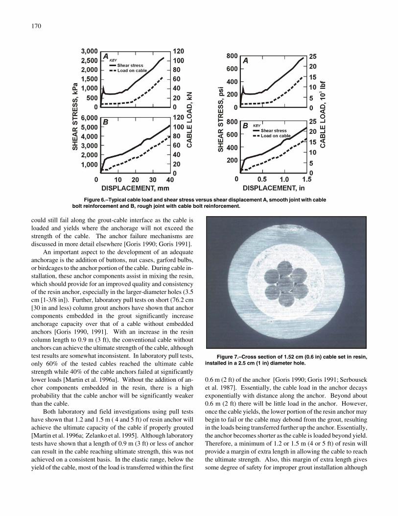
Resistance to shear and lateral movement can be developedalong the free length of the cable and result in cable loading.To determine the shear characteristics of the cables, a series oflaboratory tests were conducted where both ungrouted andgrouted cables were installed across the block boundary in pairsof concrete blocks [Goris et al. 1995; Goris et al. 1996]. Theblocks were sheared parallel to the contact surface and per-pendicular to the installed cable bolt. The results showed thatthe initial peak shear strength was not changed, but that theresidual shear strength at 3.8 cm (1.5 in) of displacement wasdoubled (figure 6). The cables were not immediately activated,but required about 1.0 cm (0.4 in) of displacement beforeresisting the shear for a 3.5-cm (1-3/8 in) in diameter hole andabout 1.52 cm (0.6 in) before significant resistance occurred.Essentially, shear is resisted only when sufficient movementhas occurred and the roof has already been mobilized.
In this series of tests, the maximum lateral displacement onthe cables was about 3.8 cm (1.5 in). None of the cables failedas a result of this level of displacement. At this point, thecables were loaded to about 60 kN (13,500 lbf), still well belowthe ultimate strength. However, in a field study, where about0.3 to 0.46 m (1 to 1.5 ft) of lateral movement occurred acrossthe entry, several cable bolts had failed. It is estimated that thecable bolts failed at between 5 to 10 cm (2 to 4 in) of lateralmovement [Dolinar et al. 1996]. The failures occurred from acombination of shear and tension.
RESIN ANCHOR
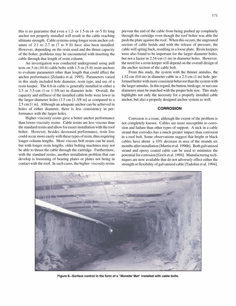
Several factors influence the effectiveness of the resinanchor, including anchor length, type of resin, and holediameter [Zelanko et al. 1995]. Figure 7 shows a cross sectionof a cable installed in resin. The cables will transfer the loadthrough the anchor to the rock with all the load transfer takingplace within the anchor length. However, if the anchor is tooshort, the anchor could slip (rock-grout interface failure),especially in weak rock. With a longer anchor, the anchor
170
Figure 6.–Typical cable load and shear stress versus shear displacement A, smooth joint with cablebolt reinforcement and B, rough joint with cable bolt reinforcement.
Figure 7.–Cross section of 1.52 cm (0.6 in) cable set in resin,installed in a 2.5 cm (1 in) diameter hole.
could still fail along the grout-cable interface as the cable isloaded and yields where the anchorage will not exceed thestrength of the cable. The anchor failure mechanisms arediscussed in more detail elsewhere [Goris 1990; Goris 1991].
An important aspect to the development of an adequateanchorage is the addition of buttons, nut cases, garford bulbs,or birdcages to the anchor portion of the cable. During cable in-stallation, these anchor components assist in mixing the resin,which should provide for an improved quality and consistencyof the resin anchor, especially in the larger-diameter holes (3.5cm [1-3/8 in]). Further, laboratory pull tests on short (76.2 cm[30 in and less) column grout anchors have shown that anchorcomponents embedded in the grout significantly increaseanchorage capacity over that of a cable without embeddedanchors [Goris 1990, 1991]. With an increase in the resincolumn length to 0.9 m (3 ft), the conventional cable withoutanchors can achieve the ultimate strength of the cable, althoughtest results are somewhat inconsistent. In laboratory pull tests,only 60% of the tested cables reached the ultimate cablestrength while 40% of the cable anchors failed at significantlylower loads [Martin et al. 1996a]. Without the addition of an-chor components embedded in the resin, there is a highprobability that the cable anchor will be significantly weakerthan the cable.
Both laboratory and field investigations using pull testshave shown that 1.2 and 1.5 m ( 4 and 5 ft) of resin anchor willachieve the ultimate capacity of the cable if properly grouted[Martin et al. 1996a; Zelanko et al. 1995]. Although laboratorytests have shown that a length of 0.9 m (3 ft) or less of anchorcan result in the cable reaching ultimate strength, this was notachieved on a consistent basis. In the elastic range, below theyield of the cable, most of the load is transferred within the first
0.6 m (2 ft) of the anchor [Goris 1990; Goris 1991; Serbouseket al. 1987]. Essentially, the cable load in the anchor decaysexponentially with distance along the anchor. Beyond about0.6 m (2 ft) there will be little load in the anchor. However,once the cable yields, the lower portion of the resin anchor maybegin to fail or the cable may debond from the grout, resultingin the loads being transferred further up the anchor. Essentially,the anchor becomes shorter as the cable is loaded beyond yield.Therefore, a minimum of 1.2 or 1.5 m (4 or 5 ft) of resin willprovide a margin of extra length in allowing the cable to reachthe ultimate strength. Also, this margin of extra length givessome degree of safety for improper grout installation although
171
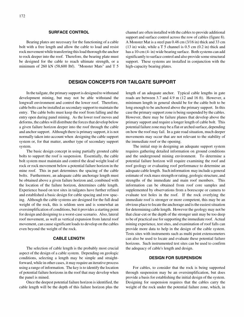
Figure 8.–Surface control in the form of a "Monster Mat" installed with cable bolts.
this is no guarantee that even a 1.2- or 1.5-m (4- or-5 ft) longanchor not properly installed will result in the cable reachingultimate strength. Cable systems using longer resin anchor col-umns of 2.1 to 2.7 m (7 to 9 ft) have also been installed.However, depending on the resin used and the thrust capacityof the bolter, problems may be encountered with inserting thecable through that length of resin column.
An investigation was conducted underground using pulltests on 3-m (10-ft) cable bolts with 1.5-m (5-ft) resin anchorsto evaluate parameters other than length that could affect theanchor performance [Zelanko et al. 1995]. Parameters variedin this study included hole diameter, resin type, and use of aresin keeper. The 0.6-in cable is generally installed in either a2.5 or 3.5-cm (1-or 1-3/8-in) in diameter hole. Overall, thecapacity and stiffness of the installed cable bolts were lower inthe larger-diameter holes (3.5 cm [1-3/8 in] as compared to a2.5 cm [1 in]. Although an adequate anchor can be achieved inholes of either diameter, there is less consistency in per-formance with the larger holes.
Higher-viscosity resins gave a better anchor performancethan lower-viscosity resins. Cable resins are less viscous thanthe standard resins and allow for easier installation with the roofbolter. However, besides decreased performance, resin losscould occur more easily with these types of resin, thus requiringlonger column lengths. More viscous bolt resins can be used,but with longer resin lengths, older bolting machines may notbe able to thrust the cable through the cartridge. Furthermore,with the standard resins, another installation problem that candevelop is loosening of bearing plates or plates not being incontact with the roof. In such cases, the higher- viscosity resins
prevent the end of the cable from being pushed up completelythrough the cartridge even though the roof bolter was able thepush the plate against the roof. When this occurs, the ungroutedsection of cable bends and with the release of pressure, thecable will spring back, resulting in a loose plate. Resin keeperswere also found to be important for the larger-diameter holes,but not a factor in 2.54-cm (1-in) in diameter holes. However,the need for a resin keeper will depend on the overall design ofthe anchor section of the cable bolt.
From this study, the system with the thinner annulus, the1.52-cm (0.6-in) in diameter cable in a 2.5-cm (1-in) hole, per-formed better with more consistent behavior than the system withthe larger annulus. In this regard, the button, birdcage, or nut casediameters must be matched with the proper hole size. This studyhighlights not only the necessity for a properly installed cableanchor, but also a properly designed anchor system as well.
CORROSION
Corrosion is a issue, although the extent of the problem isnot completely known. Cables are more susceptible to corro-sion and failure than other types of support. A nick in a cablestrand that corrodes has a much greater impact than corrosionin a roof bolt. Some observations suggest that bright or blackcables have about a 10% decrease in area of the strands sixmonths after installation [Martin et al. 1996b]. Both galvanizedstrand and epoxy coated cable can be used to minimize thepotential for corrosion [Goris et al. 1994]. Manufacturing tech-niques are now available that do not adversely effect either thestrength or flexibility of galvanized cable [Tadolini et al. 1994].
172
SURFACE CONTROL
Bearing plates are necessary for the functioning of a cablebolt with a free length and allow the cable to load and resistrock movement while transferring this load thorough the anchorto rock deeper into the roof. Therefore, the bearing plate mustbe designed for the cable to reach ultimate strength, or aminimum of 260 kN (58,600 lbf). "Monster Mats" and T 5
channel are often installed with the cables to provide additionalsupport and surface control across the row of cables (figure 8).A Monster Mat is a steel pan 0.48 cm (3/16 in) thick and 33 cm(13 in) wide, while a T 5 channel is 0.5 cm (0.2 in) thick andhas a 10-cm (4- in) wide bearing surface. Both systems can addsignificantly to surface control and also provide some structuralsupport. These systems are installed in conjunction with thehigh-capacity bearing plates.
DESIGN CONCEPTS FOR TAILGATE SUPPORT
In the tailgate, the primary support is designed to withstanddevelopment mining, but may not be able withstand thelongwall environment and control the lower roof. Therefore,cable bolts can be installed as secondary support to maintain theentry. The cable bolts must keep the roof from falling and theentry open during panel mining. As the lower roof moves anddeforms, the cables will distribute the forces that develop belowa given failure horizon deeper into the roof through the cableand anchor support. Although there is primary support, it is notnormally taken into account when designing the cable supportsystem or, for that matter, another type of secondary supportsystem.
The basic design concept in using partially grouted cablebolts to support the roof is suspension. Essentially, the cablebolt system must maintain and control the dead weight load ofrock or rock movement below a potential failure horizon in themine roof. This in part determines the spacing of the cablebolts. Furthermore, an adequate cable anchorage length mustbe obtained above a given failure horizon and, combined withthe location of the failure horizon, determines cable length.Experience based on test sites in tailgates have further refinedand established a basic design for cable spacing and row spac-ing. Although the cable systems are designed for the full deadweight of the rock, this is seldom seen and is somewhat anoversimplification of conditions, but it provides a starting pointfor design and designing to a worst-case scenario. Also, lateralroof movement, as well as vertical expansion from lateral roofmovement, can cause significant loads to develop on the cableseven beyond the weight of the rock.
CABLE LENGTH
The selection of cable length is the probably most crucialaspect of the design of a cable system. Depending on geologicconditions, selecting a length may be simple and straight-forward, while in other cases, it may require an iterative processusing a range of information. The key is to identify the locationof potential failure horizons in the roof that may develop whenthe panel is mined.
Once the deepest potential failure horizon is identified, thecable length will be the depth of this failure horizon plus the
length of an adequate anchor. Typical cable lengths in gateroads are between 3.7 and 4.9 m (12 and 16 ft). However, aminimum length in general should be for the cable bolt to belong enough to be anchored above the primary support. In thiscase the primary support zone is being suspended by the cables.However, there may be failure planes that develop above theprimary support and require a longer length of cable bolt. Thispotential failure zone may be a flat or arched surface, dependingon how the roof may fail. In a gate road situation, much deepermovements may occur that are not relevant to the stability ofthe immediate roof or the opening.
The initial step in designing an adequate support systemrequires gathering detailed information on ground conditionsand the underground mining environment. To determine apotential failure horizon will require examining the roof androof geology or evaluating roof performance to determine anadequate cable length. Such information may include a generalestimate of rock mass strength or rating, geologic structure, andstrengths of the immediate and main roof members. Thisinformation can be obtained from roof core samples andsupplemented by observations from a borescope or camera toevaluate test holes in the roof. If the rock overlying theimmediate roof is stronger or more competent, this may be anobvious place to locate the anchorage and is the easiest situationfor determining cable length. However the geology may not bethat clear-cut or the depth of the stronger unit may be too deepto be of practical use for supporting the immediate roof. Actualmining experience, test sites, and examination of roof falls canprovide more data to help in the design of the cable system.Tests sites with instruments such as multi point extensometerscan also be used to locate and evaluate these potential failurehorizons. Such instrumented test sites can be used to confirmthe adequacy of cable's length and design.
DESIGN FOR SUSPENSION
For cables, to consider that the rock is being supportedthrough suspension may be an oversimplification, but doesprovide a basis for establishing the initial design of the system.Designing for suspension requires that the cables carry theweight of the rock under the potential failure zone, which, in

173
Figure 9.–Detached block of failed roof supported by cables.
many situations, is the worst case scenario [McDonnell et al.1995]. In some situations, there will be loads that actuallyexceed rock load because of geology, horizontal stress, lateralrock movement, and mining-induced loads.
For suspension, the simplest approach is to identify aparting plane or a flat-lying, potential failure plane above thebolted roof horizon where the roof will shear at the pillar edgeof the opening and the entire weight of the rock must besupported as a detached block (figure 9). The weight of thematerial can be determined from the following equations.
Fw ' We Hp , (2)γ
where Fw ' weight of rock per linear length, kN/m (lbf/ft),
We ' effective width of opening, m (ft),
Hp ' distance from coal roof to parting plane, m (ft) ,
and ' rock density, kN/ m3 (lb/ft3).γ
If an arched roof failure is formed with the pillars carryingsome of the weight, the cables need only support the weight of therock under the arch (figure 10). The height of the arch will be de-termined by a combination of the geology, as well as by the ver-tical and horizontal stresses acting on the roof and the inducedmining stresses. Obviously, the length and the number of cables
will depend on the height of the arch, and therefore this requiresthe identification of the failure surface. The weight of the mater-ial within the arch can be estimated from the following equation.
Fa 'π4
we Ha γ , (3)
where Fa ' weight of rock under pressure arch per linear
foot, kN/m (lbf/ft),
and Ha ' height of pressure arch, m (ft).
The behavior of the pillar under different loading con-ditions will affect the width of the opening and therefore theweight of the rock that must be supported (figure 11). Thedepth of the yield zone can be determined from equationsdeveloped by Wilson and depend on the strength of the coalpillar [Wilson 1972]. The following equations can be used toestimate the depth of the yield zone. w ' pillar width in meters(feet).
(1) Rigid floor conditionsB
w ' 2 mF
ln qp % pN
(4)

174
Figure 10.–Formation of pressure arch of failed mine roof material.
Figure 11.–Formation of yield zone in coal pillar, (We '''' effective width of opening; yp1 '''' yield zone of pillar 1; yp2
'''' yield

175
w ' m qp % pN
1k& 1
&1 (5)
F 'k & 1
k%
(k & 1)2
ktan&1 k , (6)
Figure 12. –Design chart to determine yield zone width incoal pillars. A, yielding roof; B, rigid floor.
Figure 13.–Cable support design chart, where the effectivewidth of opening (We )'''' 7.6 m (25 ft) and rock density ( ) '''' 2,403γkg/m3 150 lb/ft3 [McDonnell et al. 1995].
(2) Yielding roof-floor conditionsB
where tan&1/k is expressed in radians,
m ' seam height, m (ft),
q ' overburden load, t/m2 (st/ft2),
p ' artificial edge restraint, 0 t/m2 (st/ft2),
pN ' uniaxial strength of fractured coal, 1/m2 (st/ft2),
and k ' triaxial factor ' , where N ' angle of1 % sin φ1 & sin φ
interval friction, deg.
Figure 12 shows charts developed from these equations tocalculate the depth of the yield zone. The charts were createdusing a angle of internal friction of 35E. The effective openingor roof width can then be determined from the followingequation:
We ' W + Yp1 + Yp2, (7)
where W ' mined width of opening, m (ft),
Yp1 ' yield zone for pillar 1, m (ft),
and Yp2 ' yield zone for pillar 2, m (ft).
Based on the weight of material that must be supported, thespacing of cable bolts across the opening, as well as rowspacing, can be calculated. Using a cable with a capacity of260 kN (58,600 lbf) and varying the number of cables acrossthe opening and row spacing, a design can be determined fordifferent thicknesses of rock that must be supported. Figure 13shows this design chart for an effective width of 7.6 m (25 ft)and a rock density of 2,403 kg/m3 (150 lb/ft3). This chart isbased on a flat failure surface developing at the given horizonwith the additional weight of material for the yield zone. Aseparation at 2.4 m (8 ft) would require four cables per rowwith 2.4-m (8-ft) row spacing. However, there are no safetyfactors calculated into these charts.
PERFORMANCE OF CABLE BOLTS WITH RESPECTTO TAILGATE INTERACTION ZONES
When using cable bolts for secondary support in thetailgates, there are three zones that must be considered inevaluating the design and performance of the cable systems.These zones are the outby abutment zone for both vertical and
176
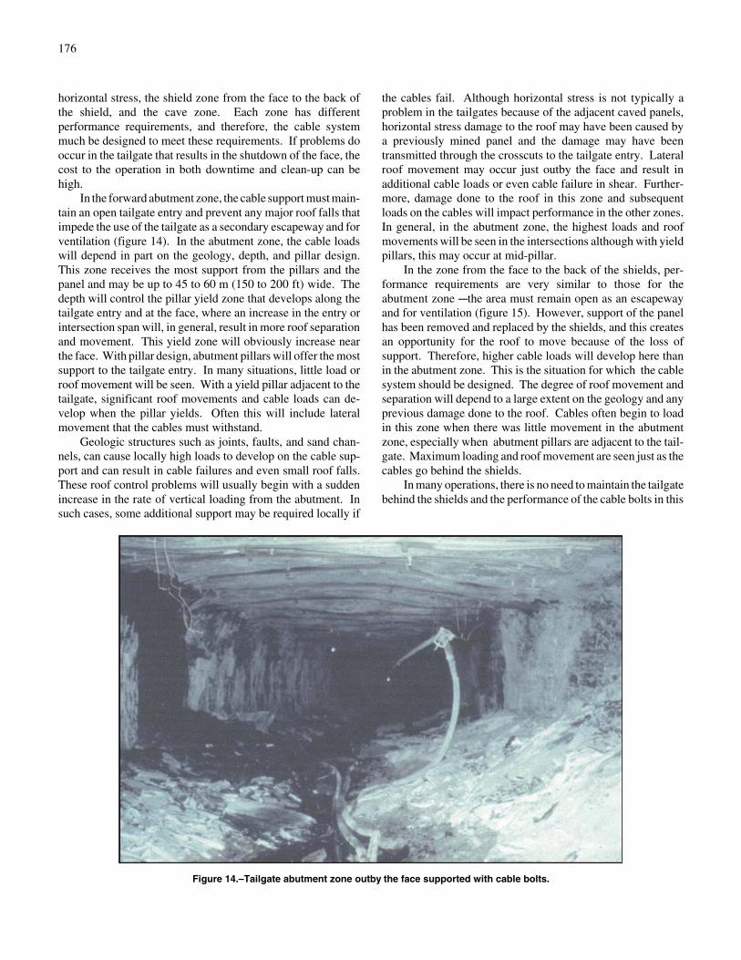
Figure 14.–Tailgate abutment zone outby the face supported with cable bolts.
horizontal stress, the shield zone from the face to the back ofthe shield, and the cave zone. Each zone has differentperformance requirements, and therefore, the cable systemmuch be designed to meet these requirements. If problems dooccur in the tailgate that results in the shutdown of the face, thecost to the operation in both downtime and clean-up can behigh.
In the forward abutment zone, the cable support must main-tain an open tailgate entry and prevent any major roof falls thatimpede the use of the tailgate as a secondary escapeway and forventilation (figure 14). In the abutment zone, the cable loadswill depend in part on the geology, depth, and pillar design.This zone receives the most support from the pillars and thepanel and may be up to 45 to 60 m (150 to 200 ft) wide. Thedepth will control the pillar yield zone that develops along thetailgate entry and at the face, where an increase in the entry orintersection span will, in general, result in more roof separationand movement. This yield zone will obviously increase nearthe face. With pillar design, abutment pillars will offer the mostsupport to the tailgate entry. In many situations, little load orroof movement will be seen. With a yield pillar adjacent to thetailgate, significant roof movements and cable loads can de-velop when the pillar yields. Often this will include lateralmovement that the cables must withstand.
Geologic structures such as joints, faults, and sand chan-nels, can cause locally high loads to develop on the cable sup-port and can result in cable failures and even small roof falls.These roof control problems will usually begin with a suddenincrease in the rate of vertical loading from the abutment. Insuch cases, some additional support may be required locally if
the cables fail. Although horizontal stress is not typically aproblem in the tailgates because of the adjacent caved panels,horizontal stress damage to the roof may have been caused bya previously mined panel and the damage may have beentransmitted through the crosscuts to the tailgate entry. Lateralroof movement may occur just outby the face and result inadditional cable loads or even cable failure in shear. Further-more, damage done to the roof in this zone and subsequentloads on the cables will impact performance in the other zones.In general, in the abutment zone, the highest loads and roofmovements will be seen in the intersections although with yieldpillars, this may occur at mid-pillar.
In the zone from the face to the back of the shields, per-formance requirements are very similar to those for theabutment zone Cthe area must remain open as an escapewayand for ventilation (figure 15). However, support of the panelhas been removed and replaced by the shields, and this createsan opportunity for the roof to move because of the loss ofsupport. Therefore, higher cable loads will develop here thanin the abutment zone. This is the situation for which the cablesystem should be designed. The degree of roof movement andseparation will depend to a large extent on the geology and anyprevious damage done to the roof. Cables often begin to loadin this zone when there was little movement in the abutmentzone, especially when abutment pillars are adjacent to the tail-gate. Maximum loading and roof movement are seen just as thecables go behind the shields.
In many operations, there is no need to maintain the tailgatebehind the shields and the performance of the cable bolts in this

177
Figure 15.–Tailgate shield zone supported by cable bolts.
area is not a factor. However, in some mines, ventilation re-quirements necessitate that the gateroad be kept at least partiallyopen to the nearest crosscut behind the face, a distance ofusually 30 to 45 m (100 to 150 ft). The maintenance of thissection of the tailgate by the cables is dependent to a largedegree on the geology and the cave and only to a limited degreeon cable system design. In the tailgate adjacent to the cave, theroof develops into a cantilever that must be supported. If theroof is not strong enough and the cave goes above the cablesthen the cantilever could fail and close most of the entry (figure16). If the roof is strong enough to maintain the cantilever, thenthe cables will help to maintain any lower weaker roof. Thecritical factors are whether the cave develops above the cablesand if the zone is strong enough to maintain the cantilever. Thecables probably add little overall strength to the cantilever.However, there are cases where the entry has stayed open morethan 45 m (100 ft) behind the face [Koehler et al. 1996; Martinet al. 1996; Mucho et al. 1996] (figure 17).
Geologic structures such as joints can cause periodic failureof even a competent roof behind the face. Essentially, there isno guarantee with cables that this zone can be maintained to thenext crosscut. If the tailgate must be kept open, then othertypes of support should be considered. However, even if theroof fails, a portion of the tailgate alongside the pillar willusually remain open, although this is a restricted area [Molindaet al. 1997].
DESIGN BASED ON TEST SITES
Test sites have been used to establish, evaluate, andconfirm cable system designs. Besides being a good practice,test sites may be required by MSHA when cable systems areused for the first time at a mine. Test sites can also be used tomodify existing cable system designs. Although observationcan be used to judge the successes of the design, instrumentsthat monitor both roof movement and separation and cableloads to quantify the results and confirm the design are pre-ferred. Monitoring of roof movement is especially useful whenevaluating cable length. Final cable system designs should bebased on evaluation of test sites.
The design most used in tailgates has been one in whichthere are four cable bolts per row. Although three bolts canprovide adequate support with the same safety factors, fourbolts per row have certain advantages. This number providesgood coverage across the entry, thus maintaining an effectivesupport front, especially as the cable row goes behind the face.Also, in a given row, the failure of a single cable represents aloss of support of only 25% with four cables per row and 33%for three cables per row. Although the cable support is de-signed on the basis of an area of support, as the support goesbehind the face, the performance of a single row or the line ofsupport becomes important. Finally, with the use of double-boom bolters, it is usually more efficient to install four bolts

178
Figure 16.–Tailgate behind the shields has caved thoughsupported with cable bolts.
Figure 17.–Tailgate behind the shields kept open with cable bolts.
than three bolts per row. Row spacing has varied from 1.2 to1.8 m (4 to 6 ft). With row spacings wider than 1.8 m (6 ft),interaction between rows can be lost and the effectiveness ofthe reinforcement as a system reduced.
Additional support to the crosscuts must also be consideredwhen using cable bolts because of the increased spans in theintersections and any damage in the crosscuts from previouspanels. Generally, this support can consist of one or two rowsof cables installed in the crosscuts. Instead of (or inconjunction with) the cables, cribs can also be set in thecrosscuts. Another modification to the design is to angle theoutside cable bolts toward the pillars and panel. This angle isusually about 10E from vertical and will allow the anchorage tobe in a more stable roof zone.
DESIGNS FOR LATERAL MOVEMENT
Cable bolts will offer resistance to lateral movement, al-though shear is resisted to a large degree only after the peak rockstrength has been exceeded. Essentially, the rock has failed andis now mobilized where the cables will offer significant post-failure resistance by significantly increasing the residual shear ofthe rock [Goris et al. 1995, 1996]. However, in some cases, be-cause of large lateral deformations, the cables may not be able tostop or limit this displacement prior to failing. At a mine inwestern Colorado, a tailgate supported with cable bolts wassubjected to large lateral deformation. This occurred as the ad-jacent panel was being mined, with the horizontal stress abutmentin the headgate causing roof damage not only to the headgate,
but also to the tailgate of the next panel through the crosscuts[Dolinar et al. 1996]. This panel was supported with cable boltsand rigid trusses. About 0.3 to 0.45 m (1 to 1.5 ft) of lateralmovement occurred in places along this entry. All the rigid trusscross bars had been thrown from the anchor bolts while about20% of the cable bolts failed. It is estimated that the cableswithstood about 5 to 10 cm (2 to 4 in) of lateral movement beforefailure. These are very tough ground conditions where few sup-port systems could be expected to prevent movement of thismagnitude. With shear or lateral movement, the flexibility of thecable bolts is not fully utilized.

179
Obviously, it may be difficult or impossible to stop suchlarge movements with support, and other approaches may needto be considered to prevent support failure. If the support doesnot fail, then it can support the damaged roof by suspension.However, there are some alternative approaches that can beused to minimize the impact of large lateral movements oncable supports. One approach is to keep the cable bolts out ofthe highest zones of shear or differential lateral movements thatoccur near the edge of the pillar. To do this, cables can be po-sitioned 0.6 to 0.9 m (2 to 3 ft) from the rib. Another successful
approach is to use cable bolts with a yielding head. Theseheads will allow the cable system to yield in a controlledmanner at loads below the ultimate capacity of the cables[Tadolini and McDonnell 1998; Vandekraats and Watson1996]. Some of these heads will allow up to 50 cm (20 in) ofcontrolled movement, thus letting the cable deform with theroof. With nonyielding cable heads, the head will lock in thebolt, and stretch in the system must take place as the bolt goesinto a yield condition.
CASE HISTORIES OF CABLE BOLTS AS SECONDARY SUPPORT IN TAILGATES
The following section gives case histories for tailgatessupported with cable bolts either as the main or only secondarysupport system. In each of these cases, a 1.52-cm (0.6-in) indiameter cable bolt with an ultimate capacity of 260 kN (58,600lbf) was used. At these test sites, cable loads were monitoredusually with hydraulic U-cells and pressure pads, while dif-ferential roof sag measurements were made within and abovethe cable horizon. Roof-to-floor convergence measurementswere also obtained at some sites. Usually, several intersectionsas well as midpillar locations were monitored.
CASE HISTORY 1
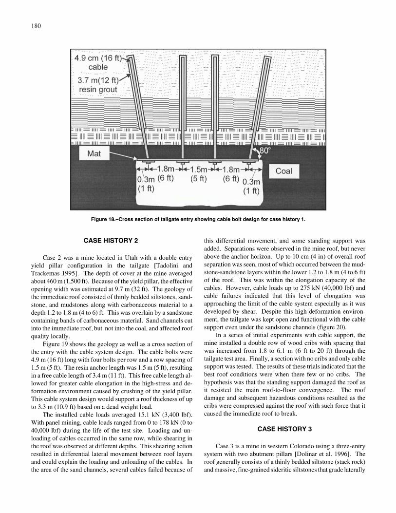
This mine is located in western Colorado and used a yield-abutment pillar configuration. Three different cable bolt systemdesigns were tested in a 274-m-(900- ft-long) section of thetailgate. They included a passive system, a stiff passive system(increased grout anchorage length), and a tensionable system[McDonnel et al. 1995; Tadolini and Koch 1993; Tadolini andKoch 1994]. The roof geology consisted of 1.2 m (4 ft) of coaloverlain by 0.6 m (2 ft) of silty shale and 1.2 m (4 ft) ofinterbedded shale, silty shale, and sandstone. After evaluatingthe geologic data on the roof, it was thought that roof separationwould most likely occur in the silty shale although separationmight also develop higher in the interbedded shale andsandstone. Above the immediate roof was a 4.9-m-(16- ft-)thick massive sandstone. This sandstone provided a good an-chorage from which to suspend the lower roof. The entry widthwas 5.8 m (19 ft), but with pillar yield, the effective width fordesign was assumed to be 7.9 m (26 ft).
Figure 18 shows a tailgate entry cross section with thecable configuration where four cables per row were installed on1.5-m (5-ft) row spacings. The cable bolts were 4.9 m (16 ft)long. With this configuration, the cables would have justenough capacity to hold up 3 m (10 ft) of rock if the separationoccurred at this level and the full weight had to be supported bythe cables. For surface control, bearing plates, monster mats,and wire mesh were used. For the passive site, the cables wereinstalled with a resin grout length of 1.7 m (5.7 ft), which
assured adequate anchorage in the sandstone and resulted in afree cable length of 3.1 m (10.3 ft). For the stiff passivesystem, the resin anchor length was 3.7 m (12 ft), leaving only1.2 m (4 ft) of free cable length. In the tensional section, theresin length was again 1.7 m (5.7 ft) with a free cable length of3.1 m (10.3 ft). These cables were tensioned to 35 kN (8,000lbf). Because of the thrust from the roof bolter, the cables in thepassive sections were installed with 6.7 to 22.2 kN (1,500 to5,000 lbf) of load.
With panel mining in the passive area, the maximum totalroof separation was about 0.6 cm (0.25 in) in an intersection.In the stiff and tensional areas, the maximum total separationwas between 3.2 and 3.8 cm (1.25 and 1.5 in) in both sections.The movement and separation took place within 30 m (100 ft)of the face and did not affect functioning of the tailgate or loadthe support beyond the cable's strength. Cable loads in thepassive section ranged from 0 to 107 kN (0 to 24,000 lbf) andaveraged 21.3 kN (4,800 lbf). In the stiff section, cable loadsalongside the shields ranged from 71 to 116 kN (16,000 to26,000 lbf). For the tensioned cable site, the loads ranged from18.2 to 151 kN (4,100 to 34,000 lbf). However, in thetensioned test site area, several geologic features, including coalspars and a clay dike, were observed in the roof. In one smallarea, the cables were loaded to over 133 kN (30,000 lbf), whilethe roof was broken and fractured. In this area, some cablesappeared to have failed or the cable heads had slipped. Ninewood posts were set to provide additional support, although thesection through the area was mined without incident. In thepassive area, the roof remained open 30 to 45 m (100 to 150 ft)behind the face, while for the stiff system, the entry remainedopen about 30 m (100 ft) behind the face.
All three systems worked extremely well and were able tokeep the tailgate open through the abutment zone, alongside theshields, and even for a distance behind the shields. However,from these test sites, it could not be determined if there were anydifference in performance among the systems. In the tensionalarea, localized geologic structure in the immediate roof did inducehigher cable loads and possibly cable failures, but no significantproblems were apparent in controlling the roof.
180
Figure 18.–Cross section of tailgate entry showing cable bolt design for case history 1.
CASE HISTORY 2
Case 2 was a mine located in Utah with a double entryyield pillar configuration in the tailgate [Tadolini andTrackemas 1995]. The depth of cover at the mine averagedabout 460 m (1,500 ft). Because of the yield pillar, the effectiveopening width was estimated at 9.7 m (32 ft). The geology ofthe immediate roof consisted of thinly bedded siltstones, sand-stone, and mudstones along with carbonaceous material to adepth 1.2 to 1.8 m (4 to 6) ft. This was overlain by a sandstonecontaining bands of carbonaceous material. Sand channels cutinto the immediate roof, but not into the coal, and affected roofquality locally.
Figure 19 shows the geology as well as a cross section ofthe entry with the cable system design. The cable bolts were4.9 m (16 ft) long with four bolts per row and a row spacing of1.5 m (5 ft). The resin anchor length was 1.5 m (5 ft), resultingin a free cable length of 3.4 m (11 ft). This free cable length al-lowed for greater cable elongation in the high-stress and de-formation environment caused by crushing of the yield pillar.This cable system design would support a roof thickness of upto 3.3 m (10.9 ft) based on a dead weight load.
The installed cable loads averaged 15.1 kN (3,400 lbf).With panel mining, cable loads ranged from 0 to 178 kN (0 to40,000 lbf) during the life of the test site. Loading and un-loading of cables occurred in the same row, while shearing inthe roof was observed at different depths. This shearing actionresulted in differential lateral movement between roof layersand could explain the loading and unloading of the cables. Inthe area of the sand channels, several cables failed because of
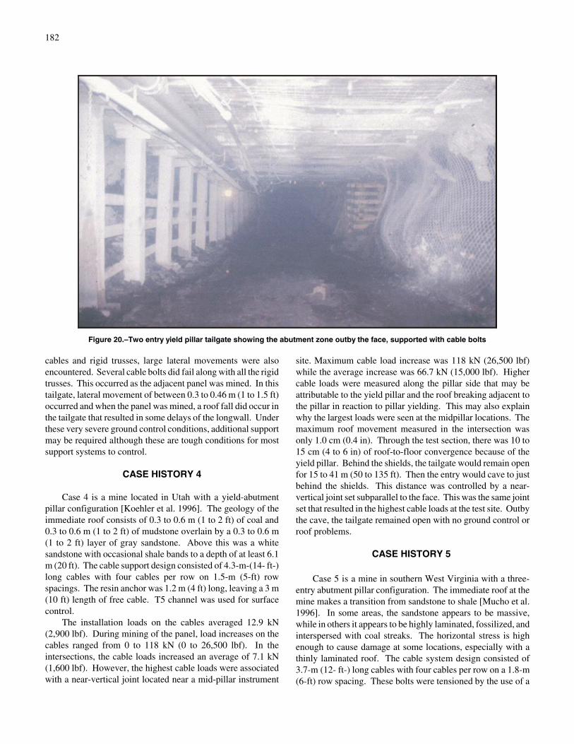
this differential movement, and some standing support wasadded. Separations were observed in the mine roof, but neverabove the anchor horizon. Up to 10 cm (4 in) of overall roofseparation was seen, most of which occurred between the mud-stone-sandstone layers within the lower 1.2 to 1.8 m (4 to 6 ft)of the roof. This was within the elongation capacity of thecables. However, cable loads up to 275 kN (40,000 lbf) andcable failures indicated that this level of elongation wasapproaching the limit of the cable system especially as it wasdeveloped by shear. Despite this high-deformation environ-ment, the tailgate was kept open and functional with the cablesupport even under the sandstone channels (figure 20).
In a series of initial experiments with cable support, themine installed a double row of wood cribs with spacing thatwas increased from 1.8 to 6.1 m (6 ft to 20 ft) through thetailgate test area. Finally, a section with no cribs and only cablesupport was tested. The results of these trials indicated that thebest roof conditions were when there few or no cribs. Thehypothesis was that the standing support damaged the roof asit resisted the main roof-to-floor convergence. The roofdamage and subsequent hazardous conditions resulted as thecribs were compressed against the roof with such force that itcaused the immediate roof to break.
CASE HISTORY 3
Case 3 is a mine in western Colorado using a three-entrysystem with two abutment pillars [Dolinar et al. 1996]. Theroof generally consists of a thinly bedded siltstone (stack rock)and massive, fine-grained sideritic siltstones that grade laterally

181
Figure 19.–Cross section of tailgate entry showing cable bolt design for case history 2.
to a dark gray limestone and to sandstone. Another seam over-lies the mined seam at distances ranging from 0.9 to 5.5 m (3 to18 ft). The thickness of the interburden is important to the roofcontrol problems that develop at the mine. The mine is alsosubjected to high horizontal stresses with a ratio of maximumhorizontal to vertical stresses of 1.7.
Test sites were established in tailgates of two adjacentpanels. Figure 21 shows the geologic column and an entrycross section with the cable support design. The cables were4.9 m (16 ft) long with four cables per row with a row spacingof 1.5 m (5 ft). Anchorage length was 1.5 m (5 ft), leaving afree cable length of 3.4 m (11 ft). In addition, high-capacitydome-bearing plates as well as monster mats were installed forsurface control. At the initial test site, the interburden was 1.8m (6 ft). Since this was the first use of cables at this operation,a double row of cribs was installed as additional support. Evenwith the crib support, cable loads averaged 98 kN (22,000 lbf),while a total of nine cables failed in the 122-m (400-ft) testzone. The failure was due to the large lateral movements thatoccurred in the interburden. Roof separation ranged from 2.0to 5.3 cm (0.8 to 2.1 in) and occurred between 1.2 to 1.8 m (4
to 6 ft) into the roof. Cribs in the test site were highly deformedby the lateral roof movement.
At the second site in the adjacent panel, interburdenthickness was 5.5 m (18 ft). The maximum increase in cableloads was 56.9 kN (12,800 lbf) with an average increase of only2.2 kN (500 lbf). The different sag stations showed less than1.8 cm (0.7 in) of movement. Roof conditions remained ex-cellent, and no roof control problems were encountered in theentire cable section. Often the roof would remain standing oneor more crosscuts behind the face, a distance of about 45 to 90m (150 to 300 ft).
The difference between the two sites was the interburden.The thinner interburden consisted of weaker layers rock (stackrock) subject to horizontal stress damage and lateral movement.With the extensive lateral movement at the first site, acombination of cribs and cables did maintain the tailgate.However, the cribs did little to stop the lateral movement, andthe cables may have been able to maintain the gate road withoutthe cribs. With less lateral movement, the gate road probablycould have been easily maintained with the cable support. In athird tailgate with a thin interburden and supported only by
182
Figure 20.–Two entry yield pillar tailgate showing the abutment zone outby the face, supported with cable bolts
cables and rigid trusses, large lateral movements were alsoencountered. Several cable bolts did fail along with all the rigidtrusses. This occurred as the adjacent panel was mined. In thistailgate, lateral movement of between 0.3 to 0.46 m (1 to 1.5 ft)occurred and when the panel was mined, a roof fall did occur inthe tailgate that resulted in some delays of the longwall. Underthese very severe ground control conditions, additional supportmay be required although these are tough conditions for mostsupport systems to control.
CASE HISTORY 4
Case 4 is a mine located in Utah with a yield-abutmentpillar configuration [Koehler et al. 1996]. The geology of theimmediate roof consists of 0.3 to 0.6 m (1 to 2 ft) of coal and0.3 to 0.6 m (1 to 2 ft) of mudstone overlain by a 0.3 to 0.6 m(1 to 2 ft) layer of gray sandstone. Above this was a whitesandstone with occasional shale bands to a depth of at least 6.1m (20 ft). The cable support design consisted of 4.3-m-(14- ft-)long cables with four cables per row on 1.5-m (5-ft) rowspacings. The resin anchor was 1.2 m (4 ft) long, leaving a 3 m(10 ft) length of free cable. T5 channel was used for surfacecontrol.
The installation loads on the cables averaged 12.9 kN(2,900 lbf). During mining of the panel, load increases on thecables ranged from 0 to 118 kN (0 to 26,500 lbf). In theintersections, the cable loads increased an average of 7.1 kN(1,600 lbf). However, the highest cable loads were associatedwith a near-vertical joint located near a mid-pillar instrument
site. Maximum cable load increase was 118 kN (26,500 lbf)while the average increase was 66.7 kN (15,000 lbf). Highercable loads were measured along the pillar side that may beattributable to the yield pillar and the roof breaking adjacent tothe pillar in reaction to pillar yielding. This may also explainwhy the largest loads were seen at the midpillar locations. Themaximum roof movement measured in the intersection wasonly 1.0 cm (0.4 in). Through the test section, there was 10 to15 cm (4 to 6 in) of roof-to-floor convergence because of theyield pillar. Behind the shields, the tailgate would remain openfor 15 to 41 m (50 to 135 ft). Then the entry would cave to justbehind the shields. This distance was controlled by a near-vertical joint set subparallel to the face. This was the same jointset that resulted in the highest cable loads at the test site. Outbythe cave, the tailgate remained open with no ground control orroof problems.
CASE HISTORY 5
Case 5 is a mine in southern West Virginia with a three-entry abutment pillar configuration. The immediate roof at themine makes a transition from sandstone to shale [Mucho et al.1996]. In some areas, the sandstone appears to be massive,while in others it appears to be highly laminated, fossilized, andinterspersed with coal streaks. The horizontal stress is highenough to cause damage at some locations, especially with athinly laminated roof. The cable system design consisted of3.7-m (12- ft-) long cables with four cables per row on a 1.8-m(6-ft) row spacing. These bolts were tensioned by the use of a

183
Figure 21.–Cross section of tailgate entry showing cable bolt design for case history 3.
threaded rebar head at the bottom end of the cable. The resinanchor was 1.5 m (5 ft) long.
When the panel was mined, less than 0.25 cm (0.1 in) ofroof separation was recorded and cable loads increased onaverage only 8.9 kN (2,000 lbf). Maximum loads and roofseparations occurred as the instruments went behind the shields.The tailgate roof area was extremely stable outby the
cave. Behind the face, the roof stayed up for a distance of 23 m(75 ft) before the roof caved to just behind the shields. Thiscyclical caving of the tailgate roof occurred throughout the testarea. In addition, when the adjacent panel was mined, therewas almost no floor heave in the cable section (tenths of inches)as compared to the crib section where several inches occurred.

184
CABLE TRUSSES
Cables trusses are anchored over the pillars and panelsoutside the potential failure envelope and provide resistance toroof movement along the roof line. Because cable trusses havea high strength and flexibility and a low stiffness, they cansurvive in a high-deformation and stress environment whereother supports would fail. Essentially, cable trusses move anddeform with the rock with the truss providing only limitedresistance to vertical movement [Scott 1994]. Some systemscan be pretensioned, but tensioning is probably not significantto improved ground control, but that assures the truss is tightwhen installed and therefore can respond immediately to roofmovement. Cable trusses have been used in mines since at leastthe 1970s, but on a limited basis [Scott 1989; Mangelsdorf1982]. However, in the 1990's with the advent of cable boltingin U.S. coal mines, newly designed cable truss systems that canbe installed with roof bolters and anchored with resin groutcartridges are now being used much more extensively assupplemental support, especially in headgate entries.
DESCRIPTION
Cable trusses are constructed from a seven strand cableusually having a diameter of 1.52 cm (0.6 in) and an ultimatestrength of 260 kN (58,600 lbf). However, cables with adiameter of 1.27 cm (0.5 in) are also used. Cable trusses arenormally installed in a hole 3.5 cm (1-3/8 in) in diameter,although the system can be installed in a 2.5-cm (1-in) hole.The drill holes are typically up 2.4 m (8 ft) deep and drilled 0.6m (2 ft) from the rib at an angle of about 45E over the coal rib.Domed and grooved bearing plates usually 15 by 40 cm (6 by16 in) in size are used as bearing surfaces for the rock andcable. This allows for a two-point contact along the roof atinstallation. At the drill hole-roof interface, the cable will alsobe in contact with the rock, and a crushed zone may develop asthe cable loads. Cable trusses may be composed of either singleor multiple pieces, which affect how the systems are installedbut not their function.
A one-piece truss consists of a single, continuous cablewith anchorage buttons and a resin mixer on each end of thecable in the anchor zone (figure 22) [Dolinar et al. 1996]. Thetruss uses a no-spin system to mix the resin while a push buttonon the cable and a special bolter wrench allow for the insertionof the cable into the hole and through the resin with the roofbolter. The procedure is that one end is installed, and the resinis allowed to cure. Then the other end of the cable is placedinto the hole on the opposite side of the entry and thrust throughthe resin with the roof bolter.
With this system, installed cable truss loads ranging from15.1 to 51.6 kN (3,400 to 8,200 lbf) have been measured. Thegoal is not to develop large loads in the roof but to simply
tighten the truss so that it will provide some immediateresistance to rock movement.
The three-piece cable truss consists of two angle cablebolts and a horizontal cable member (figure 23) [Oldsen et al.1995]. The angle bolts can be constructed with nuts orbirdcages for anchorage as well as resin keepers. The cablebolts are pushed and rotated into the hole and through the resinusing a special wrench and a roof bolter. A splice tubeassembly is attached to the angle and the horizontal cables,which allows the pieces to be connected and the system to betensioned. The housing and wedge assembly that form thecable heads are installed in the field and allow the cables to betensioned against the splice tube. A tensioner powered by thehydraulics of the bolter is used to tension the system and at upto 71.2 kN (16,000 lbf) of preload.
ANALYSIS OF CABLE TRUSS LOADING
The loads developed in a truss can be evaluated by simplestatics. Figure 24 shows a simple free-body diagram of theloads for a half of a truss. The following equations can be usedto describe the relationship between the reaction force R brokeninto horizontal and vertical components and the cord tensions.
Yr'T sin % (8)
Xr' H-T cos % (9)
where T ' tension in the diagonal member,
H ' tension in the horizontal member,
Yr ' vertical reaction force,
Xr ' horizontal reaction force,
and % ' angle of inclination of the cable.
The reaction force R may be a compilation of severalforces, especially in the case where the inclined cable bearsagainst the roof at the drill hole. However, these equations arestill valid for describing the vertical force Yr applied to the rockby the truss or to the truss by the rock [Mangelsdorf 1979].With a cable truss, the tension transfer between the horizontalcord and the diagonal cords becomes more complex. Figure 25shows a free-body diagram for the more complex loadingconditions for a cable truss. Essentially, tension load transferwill take place by slippage of the cable over the bearing blockor plate, the bearing block or plate over the rock, or the cable

185
Figure 22.– Single piece cable truss.
Figure 23.–Three piece cable truss.
over the rock at the edge of the borehole. These load transfersare dependent on overcoming these frictional forces. Becauseof these complex loading conditions, the tension in all three legs
of the truss must be measured along with roof sag to evaluatefield performance.

186
Figure 24.–Free body diagram of half truss showing the truss loads.
Figure 25.–Free body diagram of half cable truss, showing static loads that develop.
LABORATORY TESTS TO EVALUATE CABLETRUSS PERFORMANCE
Laboratory investigations have been conducted to evaluatethe loading characteristics of cable trusses where special loadframes have been constructed to approximate the field con-ditions. The results from a series of tests conducted at the Uni-versity of Pittsburgh indicate that only about 80% of the load istransferred from the angle member to the horizontal member asa result of friction across the contact blocks or bearing plates[Mangelsdorf 1979]. In these tests, the angle member was at a45E angle to the horizontal. When tested to failure, the load inthe diagonal cord member was 88.9 kN (20,000 lbf) where theultimate strength of the 1.27-cm (0.5-in) in diameter cable was102.3 kN (23,000 lbf). The angle member achieved only 87%of the ultimate load of the cable, with failure resulting from
bending of the cable over the contact block, which caused apoint of stress concentration and reduced the range of inelasticdeformation of the truss. The truss had reached the yield pointat the same approximate level as cable yield. At failure, thevertical load calculated from the load measured in the cablediagonal was 62.3 kN (14,000 lbf). The measured verticalstiffness for a half truss was 8.8 kN/cm (2.5 tons/in ) and rep-resents a stiffness of 17.5 kN/cm (5 tons/in) for the full truss.
Investigators at the University of West Virginia have alsoconducted laboratory tests with cable trusses in a speciallydesigned truss frame [Oldsen et al. 1995]. The results of thesetests were similar to those in the University of Pittsburgh study.This study did however, provide some further insight into fric-tional losses and load transfer between sections of the cable andapplied loads. In these tests, a 1.52-cm (0.6-in) in diametercable truss with an ultimate strength of 260 kN (58,600 lbf) was

187
used, although the cables were not taken to failure. Again, theangle between the angle and horizontal members was 45E.
However, there are differences of interpretation of the dataregarding the vertical load capabilities of the truss. In the Uni-versity of West Virginia report, it is stated that the load on thediagonal is 222 kN (50,000 lbf) when the total applied verticalload or plate loads is 400 kN (90,000 lbf). There are twoproblems with this interpretation. First, the data are being ex-trapolated beyond the actual test data. Second, the plate loadsare assumed to be the vertical loads. Extrapolation beyond thetest data can at times be questionable, while using loads appliedat the plates as vertical stress involves uncertainties about thefrictional conditions within both the jacks used to load thetrusses and the test frame, as well as the angle of the appliedload between the test frame and the cable. Essentially, the onlyreliable measurement of vertical load should be that calculatedfrom the diagonal member. By using the diagonal load, theresult is that the vertical truss load is only 311 kN (70,000 lbf).Assuming this is near cable failure, the ratio of a vertical loadof 311 kN (70,000 lbf) to an ultimate cable load of 260 kN(58,600 lbf) is 120%. The ratio of the vertical load to the ul-timate cable strength from the University of Pittsburgh testswas 124.6:102.3 kN (28,000:23,000 lb) or 122%. Thesecalculations were based on symmetrical loading at the plates.
FIELD EVALUATION OF CABLE TRUSSPERFORMANCE
Headgate
Trusses are now being used extensively to provide supple-mental support to the headgate entry where the damage to theheadgate entry is often the result of high horizontal stresses[Mark et al. 1998; Oldsen et al. 1995]. The ability of cabletrusses to handle headgate conditions is illustrated by thefollowing case.
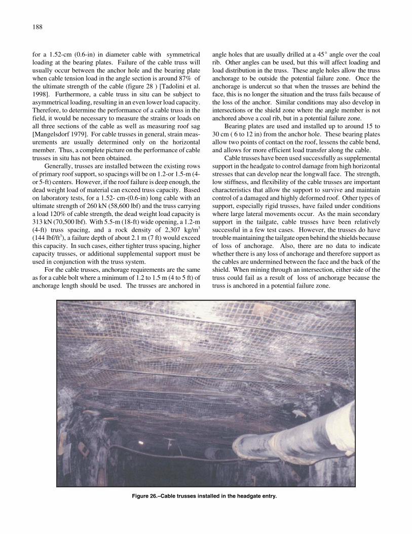
A mine located in western Colorado had roof damage in theheadgate ahead of the face as the panel was mined [Dolinar etal. 1996]. This was the result of horizontal stress concentrationahead of the face and geologic features susceptible to stressdamage. (See case 1 for a more detailed description of thegeology.) A single-piece cable truss with a diameter of 1.52 cm(0.6 in) was installed on 1.2-m (4-ft) centers in the headgateentry (figure 26). To evaluate loading during installation andas the panel was mined, special cable strain gages were installedon the horizontal section of some of the trusses. The installedload on the trusses ranged from 15.1 to 36.9 kN (3,400 to 8,200lbf). From mining, the maximum load was 74.7 kN (16,800lbf) for a truss just inby the face, an increase of 55.2 kN (12,400lbf). This shows that the cable trusses were loading and resist-ing the roof movement. The cable trusses were able to controlthe roof conditions that developed in the headgate successfullydespite the lateral movement and roof damage (figure 27).
Other investigators have measured 17.8 to 26.7 kN (4,000 to6,000 lbf) of increase resulting from horizontal stress damageand cutters in headgate situations [Oldsen et al. 1997]. In thesecases, the cable trusses also successfully controlled the roof.No cables trusses failed while the ridged trusses had.However, if failure progresses a sufficient depth into the roof,the dead weight load of the rock could exceed truss capacity.This occurred at a mine in western Kentucky where cabletrusses were installed on 1.2-m (4-ft) centers [Miller 1996].The roof failed to a rider seam when the distance to the riderwas under 3 m (10 ft) and resulted in truss failure when theweight of the rock exceeded truss capacity.
Tailgate Support
Rigid trusses have been successfully tested as the onlysecondary support in a tailgate at a test area established in amine in southwest Pennsylvania [Stankus et al. 1994]. In thetest, a section of tailgate entry 112.7 kN (370 ft) long was sup-ported by trusses on 1.2-m (4-ft) centers. Loads on thehorizontal members increased by 44.5 kN (10,000 lbf) in theabutment zone. Behind the shields, the roof did stay up for adistance of 7.3 to 9.1 m (24 to 30 ft).
Cable trusses in combination with cable bolts have alsobeen tested as the main secondary support in a section oftailgate at another mine in southwestern Pennsylvania [Molindaet al. 1997]. In this case, the cable trusses were installed on2.4-m (8-ft) centers and supplemented with one row of 3.7-m-(12- ft) long cable bolts placed along the pillar side of the entryon 1.8-m (6-ft) centers. The tailgate outby the face and alongthe shields stayed open with only minor damage to the roofbeing noted. The maximum roof separation measured was justunder 2.5 cm (1 in). Behind the shields, the trusses failedalmost immediately because of the cave and only about 25% ofthe entry remained open alongside the pillar for ventilation.This small section was kept open by the cable bolts. Even thissmall airway appears to have been closed off about three-fourths of the way to the crosscut behind the face.
Design of Cable Truss Systems
Because cable trusses have a low vertical stiffness and arevery flexible, they can deform to the shape of the roof. This, incombination with the high strength of the cable, makes the trussan excellent support where especially large lateral deformationoccurs. From the laboratory tests, measured vertical truss stiff-ness of 17.5 kN/cm (5 tons/in) is significantly lower than thestiffness of a cable bolt or a cable bolt system, where up to fourcable bolts would be used in place of the cable truss.
The loading of a truss is complex; however, based onlaboratory work, the total amount of vertical load or deadweight the cable truss can sustain appears to be about 120% ofthe ultimate strength of the cable or about 311 kN (70,000 lbf)
188
Figure 26.–Cable trusses installed in the headgate entry.
for a 1.52-cm (0.6-in) in diameter cable with symmetricalloading at the bearing plates. Failure of the cable truss willusually occur between the anchor hole and the bearing platewhen cable tension load in the angle section is around 87% ofthe ultimate strength of the cable (figure 28 ) [Tadolini et al.1998]. Furthermore, a cable truss in situ can be subject toasymmetrical loading, resulting in an even lower load capacity.Therefore, to determine the performance of a cable truss in thefield, it would be necessary to measure the strains or loads onall three sections of the cable as well as measuring roof sag[Mangelsdorf 1979]. For cable trusses in general, strain meas-urements are usually determined only on the horizontalmember. Thus, a complete picture on the performance of cabletrusses in situ has not been obtained.
Generally, trusses are installed between the existing rowsof primary roof support, so spacings will be on 1.2-or 1.5-m (4-or 5-ft) centers. However, if the roof failure is deep enough, thedead weight load of material can exceed truss capacity. Basedon laboratory tests, for a 1.52- cm-(0.6-in) long cable with anultimate strength of 260 kN (58,600 lbf) and the truss carryinga load 120% of cable strength, the dead weight load capacity is313 kN (70,500 lbf). With 5.5-m (18-ft) wide opening, a 1.2-m(4-ft) truss spacing, and a rock density of 2,307 kg/m3
(144 lbf/ft3), a failure depth of about 2.1 m (7 ft) would exceedthis capacity. In such cases, either tighter truss spacing, highercapacity trusses, or additional supplemental support must beused in conjunction with the truss system.
For the cable trusses, anchorage requirements are the sameas for a cable bolt where a minimum of 1.2 to 1.5 m (4 to 5 ft) ofanchorage length should be used. The trusses are anchored in
angle holes that are usually drilled at a 45E angle over the coalrib. Other angles can be used, but this will affect loading andload distribution in the truss. These angle holes allow the trussanchorage to be outside the potential failure zone. Once theanchorage is undercut so that when the trusses are behind theface, this is no longer the situation and the truss fails because ofthe loss of the anchor. Similar conditions may also develop inintersections or the shield zone where the angle member is notanchored above a coal rib, but in a potential failure zone.
Bearing plates are used and installed up to around 15 to30 cm ( 6 to 12 in) from the anchor hole. These bearing platesallow two points of contact on the roof, lessens the cable bend,and allows for more efficient load transfer along the cable.
Cable trusses have been used successfully as supplementalsupport in the headgate to control damage from high horizontalstresses that can develop near the longwall face. The strength,low stiffness, and flexibility of the cable trusses are importantcharacteristics that allow the support to survive and maintaincontrol of a damaged and highly deformed roof. Other types ofsupport, especially rigid trusses, have failed under conditionswhere large lateral movements occur. As the main secondarysupport in the tailgate, cable trusses have been relativelysuccessful in a few test cases. However, the trusses do havetrouble maintaining the tailgate open behind the shields becauseof loss of anchorage. Also, there are no data to indicatewhether there is any loss of anchorage and therefore support asthe cables are undermined between the face and the back of theshield. When mining through an intersection, either side of thetruss could fail as a result of loss of anchorage because thetruss is anchored in a potential failure zone.

189
Figure 27.–Roof damage from horizontal stress around cabletruss in headgate just outby the face.
Figure 28.–Shear failure of cable truss near bearing plate.
SUMMARY AND CONCLUSIONS
Cable technology as used in the longwall gate roads in U.S.coal mines was developed in the 1990's. This technologyincludes cable bolts and cable trusses. Cable bolts consist of aheaded cable utilizing a partial grout column anchor formedfrom a resin cartridge and installed with a roof bolting machine.
When evaluating cable bolts, there are several charac-teristics and components of the cable system that are importantto bolt performance. This includes cable strength, elongation,stiffness, and shear resistance, and system anchor capacity. Ingeneral, the cable should be the weakest part of the system.Therefore, to exceed the ultimate capacity of the cable, theanchorage length should be a minimum of 1.2 to 1.5 m (4 to5 ft) long. The stiffness of the cable system, the ability to resistloading, is determined by the free length and elastic propertiesof the cable. As determined from in situ pull tests, the elasticmodulus of the cable was found to be about 131.7 GPa(19.1 million lbf/in2). This value can be used to calculate cablebolt stiffness. For improved long-term performance, galvanizedwire strands or epoxy-coated cable should be used to resistcable corrosion and limit the potential for any strengthreduction of the cable. Furthermore, high- capacity bearingplates and heavy-duty mats or channel provide added protectionwith surface control and an element of structural support for theimmediate roof.
Design of cable bolt systems as secondary support in tail-gate entries is based to a large extent on suspension, althoughthis is somewhat of an oversimplification of the conditions thatcan develop. Cable lengths are determined by the depth in theroof of a potential failure horizon over the entry plus an ade-quate anchorage length. The number or density of cables willthen be determined by the dead weight load of rock below thatfailure horizon. Lateral roof movement may also cause signif-icant loads to develop in the cables where the cables resist themovement and increase the residual shear strength of the rockHowever, in some cases, the cables may not be able to stop or
limit lateral movement and, as a result, can fail. It has beenestimated that the cables can handle up to 5 to 10 cm (2 to 4 in)of lateral movement. There are measures that can be taken toreduce the potential for cable failure, including locating thebolts outside the highest lateral deformation zones or usingyielding bolt heads.
For supporting tailgates, there are three zones that must beconsidered when evaluating the design and performance of thecable system. These zones include the outby abutment zone forboth vertical and horizontal stress, the shield zone, and the cavezone. In situ tests have been used to further define and confirmcable bolt designs and performance in each of these zones. Inthese test cases, the number of cables used per row was fourwith 1.2- to 1.8-m (4-to 6-ft) row spacings. The cable lengthsat the site varied from 3.7 to 4.9 m (12 to 16 ft). These cablebolt systems were very successful in supporting longwalltailgate entries with few resulting ground control problems.
From a ground control standpoint, cable bolts have anadvantage over standing support where they do not resist mainroof-to-floor convergence. This is especially important with ayield pillar system because much of the capacity of the standingsupport will be taken up by this convergence. Although cablebolts have maintained the tailgate entry behind the shield forlong distances, the cave and roof geology are the main factorsthat determine this distance and not the cable system design.Therefore, cable bolts cannot guarantee that the tailgate can bekept open to the first crosscut behind the face for ventilation.
Cable trusses were greatly improved in conjunction withcable bolt development, and as a result, are now used moreextensively than previously, especially as supplemental supportin headgate entries. In the headgate, the cable truss has been usedto control damage caused by horizontal stress. High strength andflexibility and low stiffness are reasons why trusses can survivein a high-stress and high-deformation environment and stillfunction to maintain a highly deformed roof.

190
Furthermore, the cable truss anchorage is outside the potentialroof failure zone. Therefore, cable trusses have been successfulin providing supplemental support in critical headgate entries.
However, based on laboratory tests, the capacity of trussesto carry dead weight loads appears to be only about 120% of theultimate strength of the cable. More tests, including in situstudies, are required to determine if this capacity could be usedfor design or must be modified.
To evaluate the performance and capacity of a truss in situthough requires monitoring loads on all three cable legs along
with roof sag. Although trusses have been instrumented, to datethis has not been done to the level required for a completeevaluation of their performance. As secondary support in thetailgate entry, cable trusses have been tested or used only on alimited basis. Behind the shields, trusses can only keep the tail-gate open for a very limited distance. Beyond such distances,there are questions on how well heavily loaded trusses willperform when the anchors are undercut by mining or in in-tersections where anchors are not supported by a coal rib.
REFERENCES
Barczak TM, Zelanko JC, Molinda GM [1996]. Innovative secondarysupport systems for gate roads. In: Proceedings of Longwall U.S.A.Pittsburgh, PA: pp. 21-43.
Dolinar DR, Tadolini SC, Blackwell DV [1996]. High horizontalmovements in longwall gate roads controlled by cable support systems. In:Ozdemir L, Hanna K, Haramy KY, Peng SS, eds. Proceedings of the 15thInternational Conference on Ground Control in Mining. Golden, CO:Colorado School of Mines, pp. 497-509.
Gale WJ [1987]. Design considerations for reinforcement of coal mineroadways in Illawarra coal measures. AusIMM Ground Movement andControl Related to the Design of Coal Mines, Commonwealth Scientific andIndustrial Research Organisation (CSIRO), Australia.
Gale WJ, Fabjanczyk MW [1987]. Application of field measurementtechniques to the design of roof reinforcement systems in underground coalmines. Commonwealth Scientific and Industrial Research Organisation(CSIRO), Australia.
Goris JM [1990]. Laboratory evaluation of cable bolt systems (in twoparts). 1. Evaluation of cable supports using conventional cables. Spokane,WA: U.S. Department of the Interior, Bureau of Mines, RI 9308.
Goris JM [1991]. Laboratory evaluation of cable bolt systems (in twoparts). 2. Evaluation of cable supports using conventional cables with steelbuttons, birdcage cables and epoxy-coated cables. Spokane, WA: U.S.Department of the Interior, Bureau of Mines, RI 9342.
Goris JM, Brady TM, Martin LA [1993]. Field evaluation of cable boltsupport, Homestake mine, Lead, SD. Spokane, WA: U.S. Department of theInterior, Bureau of Mines, RI 9474.
Goris JM, Martin LA, Curtin RP [1995]. Shear behavior of cablesupports in horizontal bedded deposits. In: Proceedings of the 97th AnnualGeneral Meeting of CIM Rock Mechanics and Strata Control Session.Canadian Institute of Mining, Metallurgy and Petroleum: pp. 92-99.
Goris JM, Martin LA, Curtin RP [1996]. Shear behavior of cablesupports in horizontal bedded deposits. In: Ozdemir L, Hanna K, Haramy KY,Peng S, eds. Proceedings of the 15th International Conference on GroundControl in Mining. Golden, CO: Colorado School of Mines, pp. 497-509.
Goris JM, Nickson SD, Pakainis R [1994]. Cable colts in North America. Spokane, WA: U.S. Department of the Interior, Bureau of Mines, IC 9402.
Kadnuck LM [1994]. Mine ventilation enhancement through the use ofcable supports. SME preprint 94-36. Littleton, CO: Society for Mining,Metallurgy, and Exploration, Inc.
Karabin GJ, Hoch MT [1979]. Contemporary roof support systemsprovide a diversified approach to modern ground control. In: Proceedings ofthe 10th Annual Institute on Coal Mining Health and Safety Research.Blacksburg, VA: Virginia Polytechnic Institute and State University, pp. 249-267.
Koehler JR, DeMarco MJ, Marshall RJ, Fielder J [1996]. Performanceevaluation of a cable bolted yield-abutment gateroad system at the CrandallCanyon No. 1 Mine, Genwall Resources, Inc., Huntington, Utah. In: OzdemirL, Hanna K, Haramy KY, Peng S, eds. Proceedings of the 15th InternationalConference on Ground Control in Mining. Golden, CO: Colorado School ofMines, pp. 477-495.
Mangelsdorf CP [1979]. Evaluation of roof trusses, phase 1. Pittsburgh,PA: University of Pittsburgh, Department of Civil Engineering. U.S. Bureauof Mines grant No. G0166088.
Mangelsdorf CP [1982]. Roof truss systems and there applicationground. In: Proceedings of the Second Control in Room and Pillar MiningConference. Carbondale, IL: Southern Illinois University, pp. 113-118.
Mark C, Mucho TP, Dolinar D [1998]. Horizontal stress and longwallheadgate ground control. Min Eng Jan:61-68.
Martin L, Girard JM, Curtin RP [1996a]. Laboratory pull tests of resin-grouted cable bolts. In: Ozdemir L, Hanna K, Haramy KY, Peng S, eds.Proceedings of the 15th International Conference on Ground Control inMining. Golden, CO: Colorado School of Mines, pp. 455-468.
Martin L, Girard JM, Goris JM [1996b]. Installation and safety practicesfor cable bolts in underground mines. Spokane, WA: U.S. Department of theInterior, Bureau of Mines, IC 9441.
McDonnell JP, Tadolini SC, DiGrado PE [1995]. Field evaluation ofcable bolts for coal mine roof support. Pittsburgh, PA: U.S. Department of theInterior, Bureau of Mines, RI 9533.
Miller D [1996]. Progression of longwall gateroad support as conditionschange at Lodestar Energy's Baker Mine. In: Ozdemir L, Hanna K, HaramyKY, Peng S, eds. Proceedings of the 15th International Conference on GroundControl in Mining. Golden, CO: Colorado School of Mines, pp. 212-220.
Molinda GM, Dolinar DR, Barczak TM, Hustus J [1997]. Performanceof various standing and cribless tailgate support configurations in a largeeastern coal mine. In: Peng SS, ed. Proceedings of the 16th InternationalConference on Ground Control in Mining. Morgantown, WV: West VirginiaUniversity, pp. 9-15.
Mucho TP, Barczak TM, Dolinar DR., Bower J, Bryja J [1999]. Designmethodology for longwall tailgate secondary support. In: Proceedings ofLongwall U.S.A. Pittsburgh, PA: pp. 150-170.
Mucho TP, Compton CS, Oyler DC, Zelanko JC, Horvath S [1996]. Anevaluation of strata behavior and tailgate support performance of Eagle Nestmine. In: Ozdemir L, Hanna K, Haramy KY, Peng SS, eds. Proceedings of the15th International Conference on Ground Control in Mining. Golden, CO:Colorado School of Mines, pp. 523-526.
Oldsen, JG, Stankus J, Gou S, Khair AW [1997]. Continuingdevelopment of innovative cable support systems. In: Peng SS, ed.Proceedings of the 16th International Conference on Ground Control inMining. Morgantown, WV: West Virginia University, pp. 117-129.
Scott JJ [1989]. Roof bolting a sophisticated art. Coal Age, August.Scott JJ [1994]. An entry support system to eliminate the need for timber
cribbing. In: Proceedings of the Fifth Conference on Ground Control forMidwest U.S. Coal Mines, pp. 179-189.
Serbousek MO, Signer SP [1987]. Linear load-transfer mechanics offully grouted roof bolts. Spokane, WA: U.S. Department of the Interior,Bureau of Mines, RI 9135, 17 pp.
Stankus JC, McCaffrey JJ, Peng SS [1994]. Innovative concept intailgate entry support: elimination of crib blocks through utilization of newhigh capacity roof truss systems. In: Peng SS, ed. Proceedings of the 13thInternational Conference on Ground Control in Mining. Morgantown, WV:West Virginia University, pp. 166-174.

191
Tadolini SC, Koch RL [1993]. Cable Support for improved longwallgateroad stability. In: Peng SS, ed. Proceedings of the 12th InternationalConference on Ground Control in Mining. Morgantown, WV: West VirginiaUniversity, pp. 9-15.
Tadolini SC, Koch RL [1994]. Resin-grouted cables for longwall tailgatesupport stability. In: Peng SS, ed. Proceedings of the 13th InternationalConference on Ground Control in Mining. Morgantown, WV: West VirginiaUniversity, pp. 175-184.
Tadolini SC, McDonnell JP [1998]. Recent developments in cablesupport technology. SME preprint 98-26. Littleton, CO: Society for Mining,Metallurgy, and Exploration, Inc.
Tadolini SC, Trackemas JD [1995]. Cable support for longwall gateroadstability. In: Peng SS, ed. Proceedings of the 14th International Conferenceon Ground Control in Mining. Morgantown, WV: West Virginia University,pp. 9-17.
Vandekraats JD Watson SO [1996]. Direct laboratory tensile testing ofselect yielding rock bolt systems. In: Ozdemir L, Hanna K, Haramy KY, PengSS, eds. Proceedings of the 15th International Conference on Ground Controlin Mining. Golden, CO: Colorado School of Mines, pp. 321-332.
Wilson AH [1972]. A hypothesis concerning pillar stability. Min Eng141:409-417.
Wire Rope Technical Board [1985]. Wire rope users manual, 2nd ed.Stevensville, MD: American Iron and Steel Institute.
Zelanko JC, Mucho TP, Compton CS, Long LE, Bailey PE [1995].Parameters affecting resin-anchored cable bolt performance: results of in situevaluation. In: Peng SS, ed. Proceedings of the 14th International Conferenceon Ground Control in Mining. Morgantown, WV: West Virginia University,pp. 497-509.