caldon soundtrack user manual (1)
DESCRIPTION
Caldon Soundtrack User ManualTRANSCRIPT

CALDON® ULTRASONICS
SoundTrack
User Manual
Manual IB0133 Rev. 13

IB0133 Rev. 13 SoundTrack User Manual
Caldon is a trademark of Cameron International Corporation (“Cameron”).LEFM is a registered trademark of Cameron.Modbus is a registered trademark of Modbus Organization, Inc.
Copyright © 2012 Cameron International Corporation (“Cameron”). All information containedin this publication is confidential and proprietary property of Cameron. Any reproduction or use ofthese instructions, drawings, or photographs without the express written permission of an officerof Cameron is forbidden.
All Rights Reserved.Printed in the United States of America
Manual No. IB0133, Rev. 13June 2012

SoundTrack User Manual IB0133 Rev. 13
A complete range of support services are offered. For additional information or assistance on theapplication, operations, or servicing of the SoundTrack, write or call, or visit www.c-a-m.com.
CAUTION
NO OPERATOR ACCESS IS PERMITTED IN THE UNIT. SERVICE SHOULDONLY BE PERFORMED BY QUALIFIED PERSONNEL.
IF THE EQUIPMENT IS USED IN A MANNER NOT SPECIFIED BY THEMANUFACTURER, THE PROTECTION PROVIDED BY THE EQUIPMENT MAYBE IMPAIRED.


SoundTrack User Manual IB0133 Rev. 13
June 2012 Page i Table of Contents
CONTENTS
1 INTRODUCTION..........................................................................................................................................1
1.1 System Description............................................................................................................................ 11.2 Principles of Operation...................................................................................................................... 1
2 SPECIFICATIONS........................................................................................................................................3
2.1 SoundTrack Model Number .............................................................................................................. 32.1.1 Model Number .................................................................................................................................................32.1.2 Wafer Part Code...............................................................................................................................................32.1.3 Transmitter Part Code ......................................................................................................................................42.2 Transmitter......................................................................................................................................... 52.3 Environment (Transmitter and Wafer) .............................................................................................. 62.4 Approvals........................................................................................................................................... 62.4.1 Approvals – Transmitter...................................................................................................................................62.4.2 Approvals – Wafer ...........................................................................................................................................62.5 Transmitter Figures............................................................................................................................ 72.6 Wafer Figures & Dimensions .......................................................................................................... 11
3 INSTALLATION .........................................................................................................................................13
3.1 Wafer ............................................................................................................................................... 133.2 Transmitter Unit .............................................................................................................................. 143.2.1 Electromagnetic Interference .........................................................................................................................143.3 Field Terminations........................................................................................................................... 153.4 Power Up ......................................................................................................................................... 18
4 OPERATION................................................................................................................................................19
4.1 Commissioning................................................................................................................................ 194.1.1 Diagnostics Check..........................................................................................................................................194.1.2 Interface Detection .........................................................................................................................................194.2 Theory of Operation ........................................................................................................................ 204.2.1 Sound Velocity Measurement ........................................................................................................................204.2.2 Fluid Attenuation Measurement.....................................................................................................................204.2.3 Density Calculation........................................................................................................................................204.2.4 Viscosity Calculation .....................................................................................................................................214.3 Acoustic Processing Unit (APU)..................................................................................................... 214.4 Fault Detection ................................................................................................................................ 214.5 Backplane ........................................................................................................................................ 214.6 Remote Data Communications........................................................................................................ 22
5 MAINTENANCE .........................................................................................................................................23
5.1 Introduction ..................................................................................................................................... 235.2 General Inspections - Preventative Maintenance Procedures.......................................................... 235.3 Power Supply Voltage Troubleshooting and Maintenance ............................................................. 255.4 Wafer Inspection and Transducer Cables ........................................................................................ 295.4.1 Wafer Inspection ............................................................................................................................................295.4.2 Transducer Cable Inspection Checks .............................................................................................................295.4.3 Transducer Installation Procedure..................................................................................................................305.4.4 Analog Input Alignment.................................................................................................................................315.4.5 Analog Output Verification............................................................................................................................32

IB0133 Rev. 13 SoundTrack User Manual
Table of Contents Page ii June 2012
5.4.6 Analog Output Scaling...................................................................................................................................32
6 TROUBLESHOOTING AND DIAGNOSTICS FOR THE ULTRASONICS........................................35
6.1 Diagnostics ...................................................................................................................................... 356.2 Path Troubleshooting....................................................................................................................... 366.2.1 Path Reject Status...........................................................................................................................................366.3 Troubleshooting Acoustic Signals................................................................................................... 376.3.1 Oscilloscope Setup .........................................................................................................................................376.3.2 Observed Waveform ......................................................................................................................................376.3.3 Selecting Transducer Signal Waveforms .......................................................................................................386.4 Reprogramming the Transmitter ..................................................................................................... 406.4.1 Modbus ID and Baud Rate .............................................................................................................................40
7 RECOMMENDED SPARE PARTS...........................................................................................................41
7.1 Domestic (US and Canada) ............................................................................................................. 417.2 International..................................................................................................................................... 41

SoundTrack User Manual IB0133 Rev. 13
June 2012 Page 1 Introduction
1 INTRODUCTION
1.1 System DescriptionThe Caldon® SoundTrack consists of a wafer to be mounted between pipe flanges and a transmitter forprocessing signals. It utilizes ultrasonic technology to infer the density and viscosity of the liquid passingthrough the wafer. The primary application is to detect the passing of an interface between two similarliquids in a pipeline.
SoundTrack continuously verifies that it is performing properly and initiates warnings and alarms whenunsatisfactory conditions are detected. Easy-to-interpret diagnostic information simplifies troubleshooting.
1.2 Principles of OperationSoundTrack consists of two major components, the transmitter and the wafer. Within the transmitter is anacoustic processing unit (APU) that sends and receives electronic signals to and from the acoustictransducers in the wafer. The APU processes data received from the acoustic transducers in the wafer. Theacoustic transducers, in turn, transmit and receive acoustic signals through the process liquid in the wafer.By measuring the duration of time required for an acoustic signal to cross the diameter, it is possible todetermine the velocity of sound through the liquid within the pipeline.
The velocity of sound in a liquid is directly related to the density of that liquid. By measuring the processliquid velocity of sound and temperature, it is possible to determine the relative density of the liquid. In thisway, the SoundTrack sensor can identify a density change generally associated with the passing of aninterface between two different liquids in a pipeline.
As sound passes through a liquid, there is a slight rarefaction and compaction of the molecules of theliquid. This process causes viscous shearing that absorbs acoustic energy. SoundTrack utilizes a patentedtechnique that precisely measures the energy loss of acoustic pulses through the fluid, thereby allowing theapproximate kinematic viscosity to be determined. Changes in the measured kinematic viscosity can beused to detect the passing of an interface between two different liquids in a pipeline.
In summary, SoundTrack processes ultrasonic information to determine two significant characteristics of aliquid – relative density and kinematic viscosity. This allows SoundTrack to distinguish changes in processliquid properties that are undetectable by many other instruments.

IB0133 Rev. 13 SoundTrack User Manual
Introduction Page 2 June 2012

SoundTrack User Manual IB0133 Rev. 13
June 2012 Page 3 Specifications
2 SPECIFICATIONS
2.1 SoundTrack Model Number
Each SoundTrack has a Model Number and Part Code that completely defines the construction and featuresof the wafer and transmitter. The following subsections define the Model Number and part codes.
2.1.1 Model Number
ST-T 6- 150- EXMeter Type Enclosure TypeT = Transmitter GP = NEMA 4XW = Wafer EX = Explosion Proof
Wafer Size, InchesANSI Flange Rating150300600900
2.1.2 Wafer Part Code
H S W 0 6 8 N A B 1 6 0 0 0 CH = Hydrocarbon Product Line 0 = Standard / C = Custom
Product Type: Transducer Frequency (10*MHz)2 = LEFM220C4 = LEFM240C Nominal Transducer Size:S = SoundTrack B = 1"E = LEFM200E
Flange Class:W = Wafer A = ANSI Class 150 RF
B = ANSI Class 300 RFSize (Inches) C = ANSI Class 600 RF
D = ANSI Class 900 RFSchedule:4 = Sch. 40 Material:S = Standard N = Nickle Plated Carbon Steel8 = Sch. 80

IB0133 Rev. 13 SoundTrack User Manual
Specifications Page 4 June 2012
2.1.3 Transmitter Part Code
H S T G 2 1 6 1 A B 0 0 0 0 CH = Hydrocarbon Product Line 0 = Standard / C = Custom
Product Type: Serial Options2 = LEFM220C 0 = IR Board4 = LEFM240C 8 = RS-485 / No IR BoardS = SoundTrack N = No IR BoardE = LEFM200E B = IR Board / RS-485
T = Transmitter Analog Output Options0 = None
Enclosure Type 1 = A/O 1G = NEMA 4X 2 = A/O 2X = Explosion Proof, Al 3 = A/O 1, A/O 2S = Explosion Proof, SS 4 = A/O 3
5 = A/O 1, A/O 3Power Supply 6 = A/O 2, A/O 3
1 = 120 VAc 7 = A/O 1, A/O 2, A/O 32 = 240 VAc 8 = A/O 43 = 24 VDc 9 = A/O 1, A/O 4
A = A/O 2, A/O 4Transducer Frequency (10*MHz) B = A/O 1, A/O 2, A/O 4
C = A/O 3, A/O 4Analog Input Options D = A/O 1, A/O 3, A/O 4
0 = None E = A/O 2, A/O 3, A/O 41 = A/I 1 F = A/O 1, A/O 2, A/O 3, A/O 42 = A/I 23 = A/I 1, A/I 24 = A/I 35 = A/I 1, A/I 36 = A/I 2, A/I 37 = A/I 1, A/I 2, A/I 38 = A/I 49 = A/I 1, A/I 4A = A/I 2, A/I 4B = A/I 1, A/I 2, A/I 4C = A/I 3, A/I 4D = A/I 1, A/I 3, A/I 4E = A/I 2, A/I 3, A/I 4F = A/I 1, A/I 2, A/I 3, A/I 4
SoundTrack User Manual IB0133 Rev. 13
June 2012 Page 5 Specifications
2.2 Transmitter
Material:
Explosion Proof AluminumNEMA4X Stainless Steel
Weight
Net Weight: NEMA 4X - 30 lbs. (13.6 kg)Explosion Proof - 120 lbs. (54.5 kg)(See following figures for dimensions)
Power Requirements
Voltage Supply Required: 24 VDC or,120 VAC, 50/60 Hz or,240 VAC, 50/60 Hz
Current Draw: 24 VDC – 3.0 Amps120 VAC – 0.8 Amps230 VAC – 0.6 Amps
Power Consumption: 20W (80W with heaters active)
Cable Lengths
Standard: 15 feet (approximately 5 meters); lengths up to 200' (61 meters)can be ordered
Extended Range: Special cables can be used for runs up to 1000’. ContactCameron Measurement Systems Engineering Division to discussthe needs of the application.
Pulse Outputs/Communications
Pulse Output: 0-5 VAlarm Status: 5V Normal, 0V AlarmSerial Communications: RS-232 (typical, RS-422 or RS-485 options available) Modbus
Protocol, see Caldon Modbus Specifications
Analog Outputs: 4-20mA or 0-20mA (max load 650 Ohms), up to 4 total.
Analog Inputs: 4-20mA, 0-20mA, RTD, or Frequency, up to 3 total.Meter Body Temperature RTD is standard.
IB0133 Rev. 13 SoundTrack User Manual
Specifications Page 6 June 2012
2.3 Environment (Transmitter and Wafer)Storage TemperatureWafer: -40° to 200°F (-40° to 93°C)Transmitter: -40°to 140°F (-40° to 60°C)
Operating Temperatures (See Approvals)
2.4 Approvals
2.4.1 Approvals – Transmitter
Hazardous Area Approvals: (USA and Canada)
Class I Div I Groups C and D, Conforms to UL Std 1203, Std UL 61010-1, CSA Std 22.2 No.30, CSA Std 22.2 No. 61010.1
2.4.2 Approvals – Wafer
Hazardous Area Approvals: (USA and Canada)
Class I Div I Groups C and D, Conforms to CSA Std C22.2 No.30-M1986, CSA Std C22.2No.142-M1987, ANSI/UL Std No.508, UL Std No.1203
The temperature limit of the wafer assembly is dependent on the temperature limits for thecomponents used to connect the wafer to the electronics and may limit the temperature limits for theassembled wafer. See the wafer nameplate for the temperature limit of the system as assembled.
SoundTrack User Manual IB0133 Rev. 13
June 2012 Page 7 Specifications
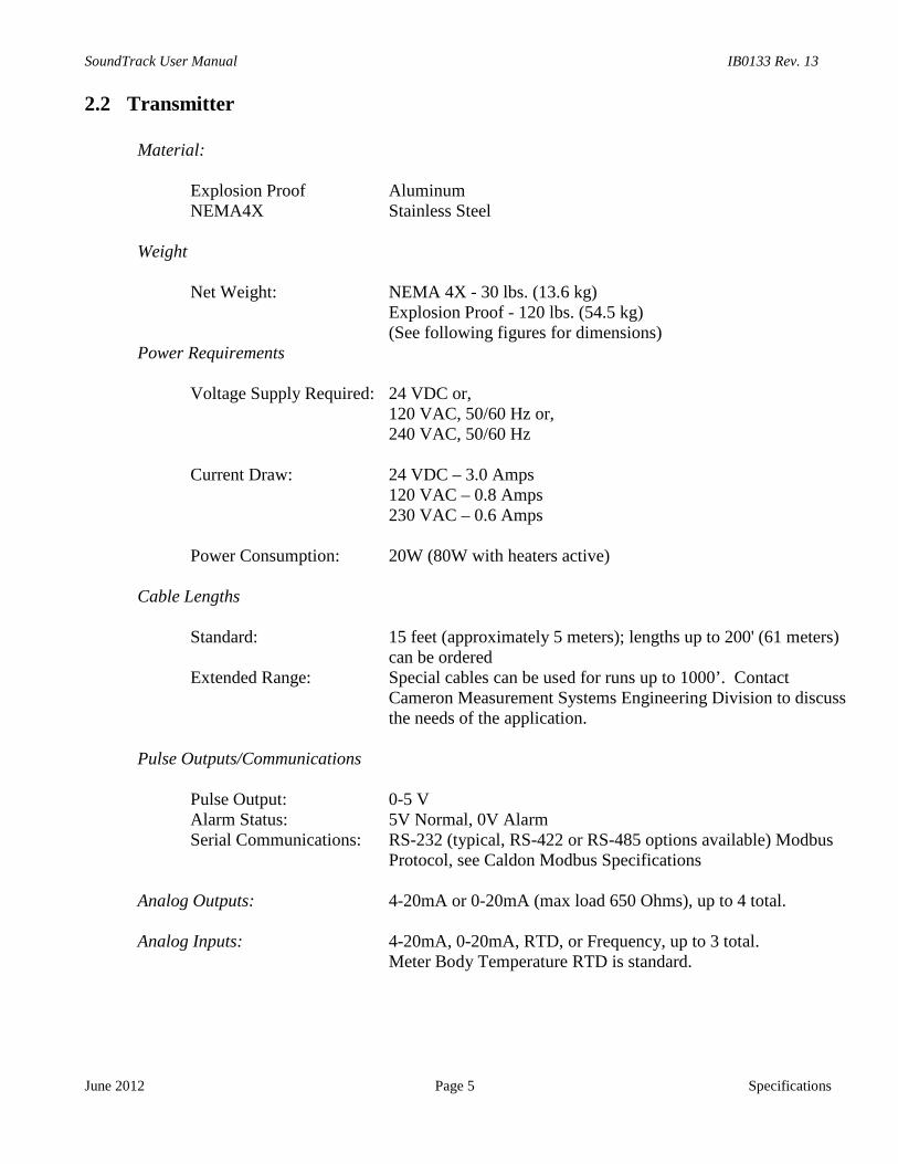
2.5 Transmitter Figures
Figure 2-1: Transmitter Unit - NEMA 4X Enclosure
MOUNTINGBRACKETS
(Use ¼ inch bolts/hardware)

IB0133 Rev. 13 SoundTrack User Manual
Specifications Page 8
Figure 2-2: Transmitter Unit - NEMA 4X with D
June 2012
oor Open

SoundTrack User Manual IB0133 Rev. 13
June 2012 Page 9 Specifications
Figure 2-3: Transmitter Unit - NEMA 7 Enclosure
(Use ½ inch bolts/hardware)
MOUNTINGBRACKETS

IB0133 Rev. 13 SoundTrack User Manual
Specifications Page 10 June 2012
Figure 2-4: Transmitter Unit – NEMA 7 with Door Open
SoundTrack User Manual IB0133 Rev. 13
June 2012 Page 11 Specifications
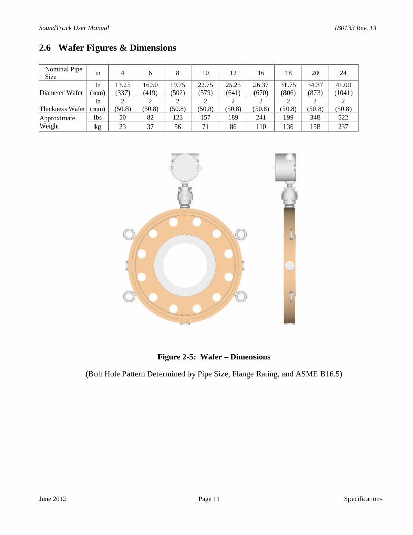
2.6 Wafer Figures & Dimensions
Nominal PipeSize
in 4 6 8 10 12 16 18 20 24
Diameter WaferIn
(mm)13.25(337)
16.50(419)
19.75(502)
22.75(579)
25.25(641)
26.37(670)
31.75(806)
34.37(873)
41.00(1041)
Thickness WaferIn
(mm)2
(50.8)2
(50.8)2
(50.8)2
(50.8)2
(50.8)2
(50.8)2
(50.8)2
(50.8)2
(50.8)
ApproximateWeight
lbs 50 82 123 157 189 241 199 348 522
kg 23 37 56 71 86 110 136 158 237
Figure 2-5: Wafer – Dimensions
(Bolt Hole Pattern Determined by Pipe Size, Flange Rating, and ASME B16.5)

IB0133 Rev. 13 SoundTrack User Manual
Specifications Page 12 June 2012

SoundTrack User Manual IB0133 Rev. 13
July 2007 Page 13 Installation
3 INSTALLATIONSteps for Installation:
1. Install wafer, Section 3.1.2. Install transmitter, Section 3.2.3. Run cable, make terminations, Section 3.3.4. Power up transmitter, Section 3.4.
3.1 WaferThe SoundTrack wafer has raised faces for mating with flanges (compliant with ANSI B16.5). It should beinstalled between similar flanges with suitable gaskets using bolts and nuts or studs and nuts. There is noneed for supports or mounting pads.
Flow can pass through the wafer in either direction. There is no requirement for flow conditioning upstreamor downstream. The wafer can be mounted adjacent to elbows, reducers, manifolds or other disruptions solong as there is no flashing or cavitation.
If the SoundTrack wafer is installed in a horizontal pipe run, it should be positioned so that the junction box(J-Box) is on top or bottom of the wafer (see Figure 2-5). This places the acoustic transducers so thatneither is directly on top or bottom.
Positioning of the transducers on the top or bottom of the wafer is not desirable because of the possibility ofair, water or deposits being present in the pipeline. Air will result in loss of acoustic signal, degrading meterperformance. Water results in an erroneous density and viscosity indication. The SoundTrack wafer canbe positioned in non-horizontal pipe runs. In all installations, the liquid must be free of entrained air (lessthan 2%) for best operation.
The wafer contains:• Two acoustic transducers that transmit and receive ultrasonic pulses passed through the fluid.• An RTD temperature transducer.
The wafer is designed to permit removal of the acoustic and temperature transducers while the pipeline isunder pressure.
IB0133 Rev. 13 SoundTrack User Manual
Installation Page 14 July 2007
3.2 Transmitter UnitThe SoundTrack transmitter is designed to be used under a wide variety of process and environmentalconditions. Durable construction permits conventional installation practices. The transmitter should beinstalled in an environment consistent with the ratings of the enclosure (i.e., NEMA 4X or NEMA 7). Allwiring to and from the transmitter must be put in grounded metal conduit. All supply power terminationsmust use the terminal blocks indicated in Table 3-7. No ventilation is required, other than that necessary tomeet the ambient temperature requirements.
For installation, simply uncrate the delivered transmitter (please note the weight of your transmitter inSection 2.0). Use the indicated mounting points/brackets for mounting the transmitter. Selectbolts/hardware appropriate for the unit’s weight. Consider site seismic requirements.
Use ½ inch bolts/hardware (or equal) on all mounting points for the Explosion Proof (NEMA 7)transmitter. Cover bolts are metric (M12 x 1.75 x 50 mm) (Use 19 mm Socket/Wrench).
Use ¼ inch bolts/hardware (or equal) on at least the 2 top and 2 bottom mounting points for theNEMA 4X transmitter.
The transmitter should be mounted at a convenient working height. (Try having the bottom of thetransmitter 4 feet (1.2 meters) from the ground.) While an installation in direct sun is acceptable, aninstallation in the shade will increase the life of all components.
The wiring should be brought to the transmitter in shielded conduit that meets site environmentspecifications. Sensor signal and power terminations should be made according to Table 3-1 through Table3-8. Explosion Proof enclosures must be installed with rigid conduit with stopping boxes / seal fittingsinstalled within 3 inches (75 mm) of the enclosure.
3.2.1 Electromagnetic Interference
The transmitter contains components that may be sensitive to strong externally generated fields and poorgrounding. To avoid electromagnetic interference, the transmitter should be located at least 10 feet fromother devices that develop strong magnetic fields (for example, electric motors, transformers, etc). Further,elimination of ground potentials between the transmitter and the wafer is strongly recommended (with theexception of galvanically protected pipelines).

SoundTrack User Manual IB0133 Rev. 13
July 2007 Page 15 Installation
3.3 Field Terminations
The following tables illustrate the connections for the SoundTrack Transmitter including the transducers,analog inputs/outputs, pulse output, serial communicating connections, and power connection.
Typical installations require the supplied cable to be wired from the wafer junction box to the transmitterterminals. Transducer connections are wired to TB-1 and RTD connections to TB-2. See Figure 2-2 orFigure 2-4 for locations of transmitter terminal blocks (TB-1 to TB-5). Refer to Table 3-1 for wiringdiagram.
The appropriate power should be wired to the power terminals (see Figure 2-2 or Figure 2-4, and Table3-7). Additional analog outputs and serial communications can be wired per Table 3-2 and Table 3-3,respectively.
The following installation instructions are for backplane’s with a green circuit board. If a blue circuitboard is installed, refer to the wiring Table 3-4 through Table 3-6.
The following figures illustrate mounting and wiring for the transmitter unit and the wafer:
Cable Identification From Transmitter To Wafer
Instrument cable/wire namewirecolor terminus terminus
"Up" Transducer
XDCR - 1 Up + Black TB1-1 J-Box TB1-1
XDCR - 1 Up Shield Clear TB1-2 -
XDCR - 1 Up - Red TB1-3 J-Box TB1-2
"Down" TransducerXDCR - 1 Dn + Black TB1-4 J-Box TB1-3
XDCR - 1 Dn Shield Clear TB1-5 -XDCR - 1 Dn - White TB1-6 J-Box TB1-4
Temperature Analog Input
RTD + Black TB2-1 J-Box TB1-6
RTD + Black TB2-2 J-Box TB1-7
RTD - Green TB2-5 J-Box TB1-5
Table 3-1: Transmitter to Wafer
Analog Output Signal Description terminus
Specific Gravity
4-20 mA + (high) TB3-1
Shield TB3-2
4-20 mA – (low) TB3-3
Viscosity4-20 mA + (high) TB3-4
Shield TB3-54-20 mA – (low) TB3-6
Temperature
4-20 mA + (high) TB3-7Shield TB3-8
4-20 mA – (low) TB3-9
Direct Gain
4-20 mA + (high) TB3-10
Shield TB3-11
4-20 mA – (low) TB3-12
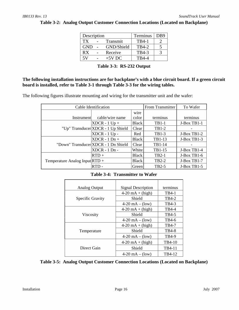
IB0133 Rev. 13 SoundTrack User Manual
Installation Page 16 July 2007
Table 3-2: Analog Output Customer Connection Locations (Located on Backplane)
Description Terminus DB9TX - Transmit TB4-1 2GND - GND/Shield TB4-2 5RX - Receive TB4-3 35V - +5V DC TB4-4
Table 3-3: RS-232 Output
The following installation instructions are for backplane’s with a blue circuit board. If a green circuitboard is installed, refer to Table 3-1 through Table 3-3 for the wiring tables.
The following figures illustrate mounting and wiring for the transmitter unit and the wafer:
Cable Identification From Transmitter To Wafer
Instrument cable/wire namewirecolor terminus terminus
"Up" TransducerXDCR - 1 Up + Black TB1-1 J-Box TB1-1
XDCR - 1 Up Shield Clear TB1-2 -XDCR - 1 Up - Red TB1-3 J-Box TB1-2
"Down" TransducerXDCR - 1 Dn + Black TB1-13 J-Box TB1-3XDCR - 1 Dn Shield Clear TB1-14 -
XDCR - 1 Dn - White TB1-15 J-Box TB1-4
Temperature Analog Input
RTD + Black TB2-1 J-Box TB1-6
RTD + Black TB2-2 J-Box TB1-7
RTD - Green TB2-5 J-Box TB1-5
Table 3-4: Transmitter to Wafer
Analog Output Signal Description terminus
Specific Gravity4-20 mA + (high) TB4-1
Shield TB4-24-20 mA – (low) TB4-3
Viscosity4-20 mA + (high) TB4-4
Shield TB4-5
4-20 mA – (low) TB4-6
Temperature
4-20 mA + (high) TB4-7
Shield TB4-8
4-20 mA – (low) TB4-9
Direct Gain
4-20 mA + (high) TB4-10
Shield TB4-11
4-20 mA – (low) TB4-12
Table 3-5: Analog Output Customer Connection Locations (Located on Backplane)

SoundTrack User Manual IB0133 Rev. 13
July 2007 Page 17 Installation
COM TerminationRS-232*
BPL-S1, S2 = RS-232
RS-422/485 Full Duplex**BPL-S1, S2 = RS-485E6, E7 jumpered 2-3
RS-485 Half Duplex**BPL-S1, S2 = RS-485E6, E7 jumpered 1-2
COM3
BPL-TB3-11 Transmit (Tx)A, Noninverting Receive
(+Rc)
BPL-TB3-12 Ground (GND)B, Inverting Receive
(-Rc)
BPL-TB3-13 Receive (Rc)Z, Inverting Transmit
(-Tx)Z, Inverting Transmit/Receive
(- Data)
BPL-TB3-14 +5 VoltsY, Noninverting Transmit
(+Tx)Y, Noninverting
Transmit/Receive (+Data)
BPL-TB3-15 Ground
COM4
BPL-TB3-16 Transmit (Tx)A, Noninverting Receive
(+Rc)
BPL-TB3-17 Ground (GND)B, Inverting Receive
(-Rc)
BPL-TB3-18 Receive (Rc)Z, Inverting Transmit
(-Tx)Z, Inverting Transmit/Receive
(- Data)
BPL-TB3-19 +5 VoltsY, Noninverting Transmit
(+Tx)Y, Noninverting
Transmit/Receive (+Data)
BPL-TB3-20 Ground
Table 3-6: RS-232, 422/485 Serial Communications
*RS-232 selected when S1 (COM3) and S2 (COM4) on the transmitter backplane are positioned toward“RS-232”.
**RS-422/484 are selected when S1 (COM3) and S2 (COM4) on the transmitter backplane are positionedtoward “RS-485”. Jumpering E6 (COM3) and E7 (COM4) on the transmitter backplane to positions 1-2selects half duplex mode (RS-485). Jumpering E6 (COM3) and E7 (COM4) on the transmitter backplaneto positions 2-3 selects full duplex mode RS-422/485).
IB0133 Rev. 13 SoundTrack User Manual
Installation Page 18 July 2007
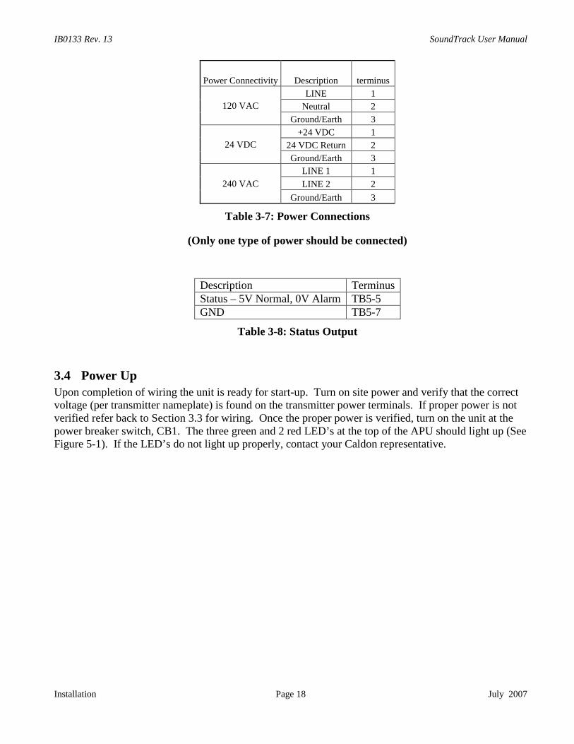
Power Connectivity Description terminus
120 VAC
LINE 1
Neutral 2
Ground/Earth 3
24 VDC
+24 VDC 1
24 VDC Return 2
Ground/Earth 3
240 VAC
LINE 1 1
LINE 2 2
Ground/Earth 3
Table 3-7: Power Connections
(Only one type of power should be connected)
Description TerminusStatus – 5V Normal, 0V Alarm TB5-5GND TB5-7
Table 3-8: Status Output
3.4 Power UpUpon completion of wiring the unit is ready for start-up. Turn on site power and verify that the correctvoltage (per transmitter nameplate) is found on the transmitter power terminals. If proper power is notverified refer back to Section 3.3 for wiring. Once the proper power is verified, turn on the unit at thepower breaker switch, CB1. The three green and 2 red LED’s at the top of the APU should light up (SeeFigure 5-1). If the LED’s do not light up properly, contact your Caldon representative.
SoundTrack User Manual IB0133 Rev. 13
July 2007 Page 19 Operation
4 OPERATION
4.1 CommissioningThe SoundTrack measures the sound velocity and viscous attenuation of the fluid in the pipeline. Theacoustic properties are then used to infer the density and viscosity of the fluid. The resulting values ofdensity and viscosity are indicators of these properties, not absolute measurements. During the initialcommissioning of the SoundTrack, care should be taken to determine how these indications match withthe expected properties in the line.
It is not unusual for the indicated viscosity or density to not exactly match the independently measuredproperties. The SoundTrack is NOT BROKEN in these cases. The relationships used to calculate thesevalues are empirical and are dependent on the fluids (particularly crudes). In cases where it is necessaryfor the SoundTrack’s indication to more closely match the actual properties of the fluid, calibrationsoftware can be used in conjunction with site samples to refine the empirical relationship. Contact yourCaldon representative for more information on the SoundTrack Calibration Software.
4.1.1 Diagnostics Check
Once the SoundTrack is installed and powered up and the line is filled with fluid, the next step incommissioning is to check the meter diagnostics. The meter diagnostics can be checked in three ways:
1. LEFMLink – Cameron supplies a general diagnostics tool called LEFMLink. This tool reads andlogs SoundTrack data from to a PC. This software is available from Cameron at no charge andcan be downloaded from the web site, www.c-a-m.com.
2. SoundTrack Calibration Program – If you are using the SoundTrack Calibration Program, youcan read diagnostic information while entering fluid information into the database. See theSoundTrack Calibration Program Manual for more information.
3. Directly from the device using Modbus. See the Modbus manual for more information.
Once the diagnostic information is available, check the following:1. Percent Rejects should be 0%.2. Status should be normal.3. Gain Up / Dn should be between 40 and 70 dB.4. Temperature should be reading a value close to line conditions.5. Echo Mode box is checked as true.
If the system fails any of the above checks verify that the wiring is correct and all the wires are firmlyconnected in the terminals. Startup problems are most commonly due to wiring problems. Refer back toSection 3.3 for wiring details.
If a computer is not available for diagnostics, check that the status indicator (TB-5-5 (+) and TB-5-7(Ground)) measures 5V. If there is a problem then the status indicator will measure 0V.
4.1.2 Interface Detection
After the system has passed the initial diagnostics check, it is ready to setup for interface detection. Ifthe SoundTrack Calibration software is being used, set it up and start using it at this time.
Set up to monitor the viscosity and density using either analog outputs or Modbus. Monitor theperformance of the SoundTrack during a known interface. This will establish a baseline for the system.

IB0133 Rev. 13 SoundTrack User Manual
Operation Page 20 June 2012
Many systems may not have a sharp change from one product to another (extended interface due toproduct mixing). However, most systems will have a characteristic shape that can be used to aid theoperator in detection of an interface.
Once the system is characterized, the operator can set limits to control the SoundTrack. This control isdependent on the user’s system, contact Caldon if assistance in required in setting up your system.
4.2 Theory of OperationThe SoundTrack uses sound velocity and fluid attenuation to infer the density and viscosity of the fluidin the line.
4.2.1 Sound Velocity Measurement
The SoundTrack uses the time of flight of an acoustic signal to calculate the velocity of sound of thefluid. The APU board in the transmitter triggers the transducer to generate an acoustic pulse. That pulsetravels through the fluid at the speed of sound in that fluid. A transducer on the opposite side of the pipecollects the pulse. The APU then calculates the time the pulse is in transit. This time is then usedcalculate the velocity of sound as follows:
fluidnondown
fluidtt
LengthC
_
4.2.2 Fluid Attenuation Measurement
The APU uses automatic gain control to measure the fluid attenuation. There are two modes ofoperation to calculate the attenuation of the fluid. In the standard mode, Pulse-Echo mode, the acousticsignal travels across the pipe once (Direct Mode) and then echoes back across the pipe a second time.The signal gain (strength) is measured for both modes.
The attenuation of the fluid is the difference between the echo and direct mode gains corrected forreflection losses.
If the echo mode is not functioning then the attenuation is calculated from the direct mode data and ahistorical correction term that was calculated when the SoundTrack was working in Echo Mode.
4.2.3 Density Calculation
The density is calculated by first calculating a general product identification density (ρPID). ρPID = f(Cf, T, P)
Where, Cf = Sound Velocity of Fluid, T = Temperature, and P = Pressure.
FiringTransducer
ReceivingTransducer
Direct Mode
Firing /ReceivingTransducer
SignalReflects
Echo Mode

SoundTrack User Manual IB0133 Rev. 13
July 2007 Page 21 Operation
The ρPID is then used to select one of ten product curves to calculate the actual density. ρ = f(Cf, T, P)
The calculated density can then be adjusted by a slope and offset to adjust for a site calibration. TheSoundTrack Calibration software can be used to adjust these curves.
4.2.4 Viscosity Calculation
The viscosity calculation uses the fluid attenuation (Ha) to select a viscosity curve to representative of aspecific fluid type. Each curve is used to calculate viscosity from attenuation, sound velocity, andtemperature. There are eleven possible curves to select from. Sound velocity is generally used forlighter fluids and attenuation is used for heavier fluids.
Once the viscosity is calculated it can then be adjusted by a slope and offset to adjust for site conditions.This adjustment can be performed simply with the SoundTrack Calibration software.
4.3 Acoustic Processing Unit (APU)The acoustic processing unit transmits and receives ultrasonic pulses and measures their transit timesand gains. From process data it computes viscosity, sound velocity, and relative density, and generatesoutputs. The acoustic processing unit is a specialized board proprietary to Caldon designed to achievehigh sampling rates and stable ultrasonic signals.The APU performs all control and timing for the generation and measurement of acoustic pulses. TheAPU has a microprocessor programmed to perform the following functions:
• Provide gain control for each ultrasonic transducer based upon acoustic signal strength• Compute viscosity and density• Generate analog outputs
Setups and Data to/from the APU are provided by a serial link (Modbus, i.e. LEFMLink).
4.4 Fault DetectionThe APU performs the following automatic fault detection:
• Checks data quality for ultrasonic transducers and evaluates data against thresholds. The data isevaluated based on SNR (signal to noise ratio), cross-correlation tests, and signal statistics.
• Occasional rejected or bad data does not influence the operation. However, if the ultrasonic pathcontinues to fail, the SoundTrack sensor will alert operators with the ALARM status and an errorcode.
The APU outputs status via Modbus. The status may be one of the following:• NORMAL status.• ALARM status: Path has no acoustic signal or is rejecting data due to low SNR, irregular
statistics or failing cross-correlation tests. Viscosity and density are set to minimum value.
The status is also output on TB-5-5. Normal operation, 5V. Alarm Operation, 0V.
4.5 BackplaneThe backplane provides the interface between the electronics, the wafer, and customer terminations. Thebackplane uses plug-in interface adapters to protect the electronics and provide easy repair andreplacement. Analog inputs plug into MB1 – 4, analog output plug into MB5 – 8, and the status bit isisolated using MB9 (See Figure 5-6).

IB0133 Rev. 13 SoundTrack User Manual
Operation Page 22 June 2012
4.6 Remote Data CommunicationsThe SoundTrack sensor has one communication port using the Modbus protocol. See the Modbusmanual for more detail.

SoundTrack User Manual IB0133 Rev. 13
J
5 MAINTENANCE
5Tps
Tms
5
T
WARNING: NO OPERATOR ACCESS IS PERMITTED IN THE UNIT. SERVICE
une 2012 Page 23 Maintenance
.1 Introductionhe purpose of this section is to provide procedures for troubleshooting and maintenance tasks whichersonnel can perform on each SoundTrack. These procedures may be incorporated into the customer’standard maintenance program.
his section includes procedures for maintaining the SoundTrack that are designed for a trainedaintenance technician to perform. These procedures may require the maintenance person to reference
chematics, system connection diagrams, and construction outlines in Section 1.
.2 General Inspections - Preventative Maintenance Procedures
his procedure covers the inspection of the electronics unit, transducers, metering sections, and cables.
DO NOT OPEN WHEN ENERGIZED!
BEFORE INSPECTING COMPONENTSOPEN THE SOUNDTRACK CIRCUIT BREAKER
TO AVOID ELECTRICAL SHOCK.
WEAR AN ESD PROTECTIVEWRIST STRAP TO AVOID
DAMAGING ANY COMPONENTS
SHOULD ONLY BE PERFORMED BY QUALIFIED PERSONNEL.
WARNING
CAUTION

IB0133 Rev. 13 SoundTrack User Manual
Maintenance Page 24 July 2007
Enclosure Inspection
Perform the following inspections on each enclosure:
a. Verify electronic unit enclosure has suffered no structural damage. Report any damage to propermaintenance supervisor.
b. Remove dust, dirt, and other soiling from enclosure. If necessary, remove power to theSoundTrack by opening circuit breaker CB1.
c. Inspect access cover gaskets. Clean gaskets and mating surfaces on enclosure with water if theyare dirty; remove any corrosion from mating surfaces. Verify gaskets compress when cover isinstalled and fastened to enclosure.
d. Inspect door latch mechanism.
e. Lubricate door hinges with lubricant specified on enclosure.
f. Inspect enclosure mounting and fastening hardware.
Internal Electronics Inspection
a. If necessary, remove power to the SoundTrack by opening circuit breaker CB1.
b. Put on an ESD (Electrostatic Discharge) protective wrist strap. Connect ESD protective wriststrap to a known ground; any part of enclosure structure is an acceptable ground.
c. Inspect cable entry points to assure that cable insulation is undamaged. Inspect cables that crosshinges to assure that cable insulation is undamaged.
d. Inspect cable connections for tightness. Clean connections if fouled or corroded with electroniccontact cleaning fluid.
e. Inspect all internal connections and terminals for tightness, clean connectors and terminals iffouled or corroded with electronic contact cleaning fluid.
f. Inspect fuses to assure that they are not damaged or discolored. Replace any damaged or blownfuses.
g. Inspect display panel components (if supplied) and devices for damage. Replace any damagedcomponents. Check all connectors to see that each is properly seated. Check that all devices aresecurely mounted.
h. Inspect acoustical processing unit (APU) components and devices for damage. Check that theprinted circuit boards are properly seated. Check that devices are securely mounted. Clean dustand grime from the surface of all components using compressed air or a PC parts cleaner.
i. Caution: Heater located behind the backplane, allow surface to cool.
j. Clean dust and grime from all surfaces of the enclosure interior walls using compressed air or aPC parts cleaner.

SoundTrack User Manual IB0133 Rev. 13
June 2012 Page 25 Maintenance
5.3 Power Supply Voltage Troubleshooting and MaintenanceWith the unit energized and the system software executing, verify by looking at the top edge of the APUcards that the following indicator lights are on:
Figure 5-1: APU LED Indicators
If any of the power supply voltage lights are not on, please check the backplane voltage (See terminalblock on Figure 5-2, See Table 5-1). If the power supplies are functioning properly, then the APU fusesmay need to be replaced. If not, then the power supply should be tested and possibly replaced.
Green LED, Normal State ON indicates +5 VDCpower supply is operating
Green LED, Normal State ON indicates +12 VDCpower supply is operating
Green LED, Normal State ON indicates -12 VDCpower supply is operating
Red LED, Normal State ON indicates +150 VDCpower supply is operating
Red LED, Normal State ON (flashing at high rate)indicates transmit pulse is operating normally
DIP Switch for Troubleshooting
TP4, Test Point 4, Test point for received ultrasonicsignal for each path
TP3, Test Point 3, Test point used for externaltrigger of an oscilloscope
Top Edge of Board
IB0133 Rev. 13 SoundTrack User Manual
Maintenance Page 26 July 2007
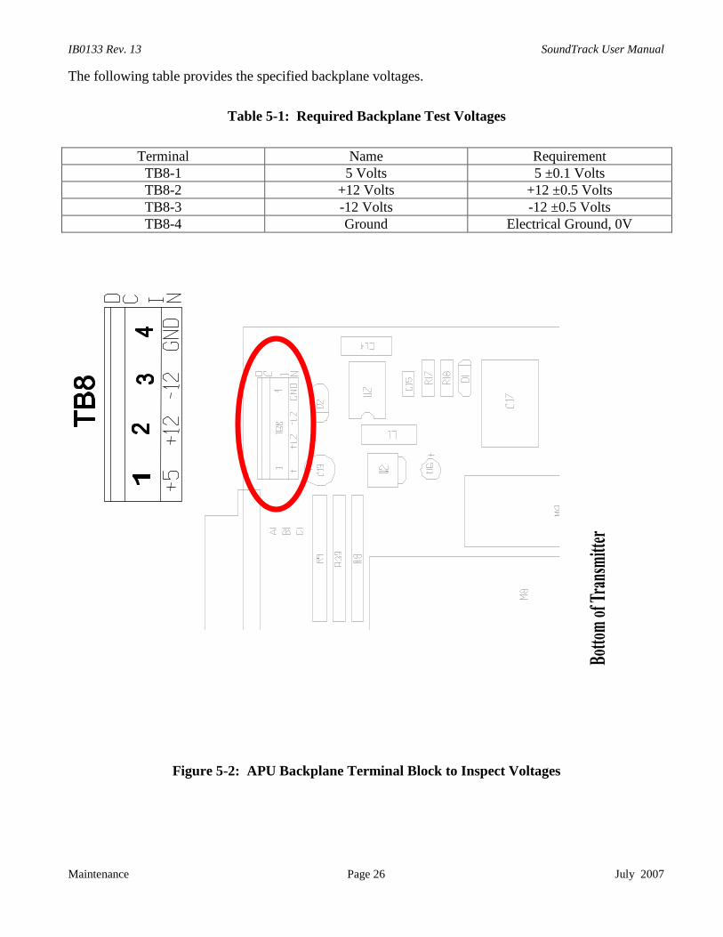
The following table provides the specified backplane voltages.
Table 5-1: Required Backplane Test Voltages
Terminal Name RequirementTB8-1 5 Volts 5 ±0.1 VoltsTB8-2 +12 Volts +12 ±0.5 VoltsTB8-3 -12 Volts -12 ±0.5 VoltsTB8-4 Ground Electrical Ground, 0V
Figure 5-2: APU Backplane Terminal Block to Inspect Voltages
SoundTrack User Manual IB0133 Rev. 13
June 2012 Page 27 Maintenance
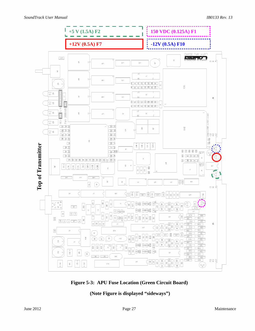
Figure 5-3: APU Fuse Location (Green Circuit Board)
(Note Figure is displayed “sideways”)
+5 V (1.5A) F2 150 VDC (0.125A) F1
+12V (0.5A) F7 -12V (0.5A) F10

IB0133 Rev. 13 SoundTrack User Manual
Maintenance Page 28
Figure 5-4: APU Fuse Location
(Note Figure is displayed
+5 V (1.5A) F2 - Very Fast Acting (FF)
+12V (0.5A) F7 - Very Fast Acting (FF)
150 VDC (0.125A) F1 – Very Fast Acting
July 2007
(Blue Circuit Board)
“sideways”)
(FF)
-12V (0.5A) F10 – Very Fast Acting (FF)

SoundTrack User Manual IB0133 Rev. 13
June 2012 Page 29 Maintenance
5.4 Wafer Inspection and Transducer Cables
5.4.1 Wafer Inspection
Perform the following inspection and maintenance tasks:a. Inspect the wafer. Verify wafer has not suffered any damage.
DO NOT OPEN WHEN ENERGIZED!
BEFORE INSPECTING COMPONENTSOPEN THE SOUNDTRACK CIRCUIT BREAKER
TO AVOID ELECTRICAL SHOCK.
b. Check connectors on transducer cables in J-Box terminal block to verify they are undamaged.Clean connectors with electronic contact cleaner if fouled or corroded. Verify all mountinghardware is secure.
5.4.2 Transducer Cable Inspection Checks
DO NOT OPEN WHEN ENERGIZED!
BEFORE INSPECTING COMPONENTSOPEN THE SOUNDTRACK CIRCUIT BREAKER
TO AVOID ELECTRICAL SHOCK.Inspect transducer cables as follows:a. Verify each transducer cable for physical damage. Check connectors on cables at each end to
verify each is undamaged. Clean connector with electronic contact cleaner if fouled or corroded.Replace any damaged cable or connector.
b. Reinstall transducer housing covers and J-box cover after completing all inspections.c. Disconnect connectors from Electronics. Check continuity and isolation of cables (shield,
positive, negative, earth ground, and impedance of transducers).d. Verify cable impedance (positive/negative disconnected from transducer and +/shield/-
disconnected from electronics) as follows:e. Positive to negative > 10MΩ f. Positive to shield > 10MΩ g. Negative to shield > 10MΩ h. Shield to earth ground > 10MΩ
WARNING
WARNING
IB0133 Rev. 13 SoundTrack User Manual
Maintenance Page 30 July 2007
i. Reinstall cables when completed.
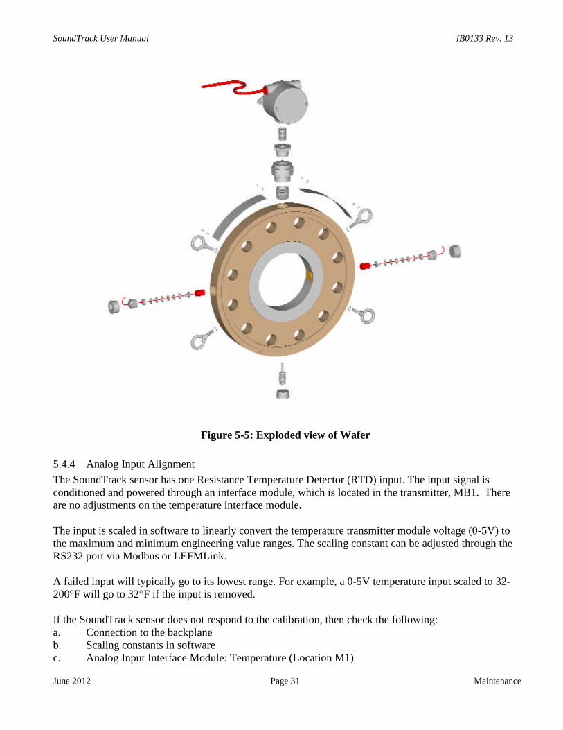
5.4.3 Transducer Installation Procedure
The SoundTrack system may require verification when a transducer is replaced or re-coupled.The transducer should be installed using the following procedures:
Step 1 Power down the SoundTrack and disconnect the transducer to be replaced from the terminalsin the J-Box.
Step 2 Remove the 1-1/4” plug covering the transducer well and route transducer wires from J-Boxthrough the wire routing channel and out from the transducer well.
Step 3 Remove transducer internals. Use a 3/4" O-ratchet to back off the compression screw. Thetransducer leads should be pulled through the back of the ratchet.
Step 4 Verify the transducer housing is clean and free from dirt.Step 5 Re-install the transducer intervals with fresh coupling material:
a) Thread the wires of the transducer though the spring assembly and the spacer (if present).b) Apply 3 drops of silicone lubricant to the transducer face before inserting into the
transducer housing or replace the coupling foil.c) Insert the transducer and components into the well until the transducer face is against the
bottom of the transducer well.d) Route the wires though the compression screw and then apply lubricant to the threads.
Screw into the transducer well and tighten. This will load the compression spring.Step 6 Route transducer wires back through the wire routing channel to the J-Box and connect the
new transducer to the J-Box terminals.Step 7 Re-install the 1-1/4” plug and J-Box cover.
SoundTrack User Manual IB0133 Rev. 13
June 2012 Page 31 Maintenance
Figure 5-5: Exploded view of Wafer
5.4.4 Analog Input Alignment
The SoundTrack sensor has one Resistance Temperature Detector (RTD) input. The input signal isconditioned and powered through an interface module, which is located in the transmitter, MB1. Thereare no adjustments on the temperature interface module.
The input is scaled in software to linearly convert the temperature transmitter module voltage (0-5V) tothe maximum and minimum engineering value ranges. The scaling constant can be adjusted through theRS232 port via Modbus or LEFMLink.
A failed input will typically go to its lowest range. For example, a 0-5V temperature input scaled to 32-200°F will go to 32°F if the input is removed.
If the SoundTrack sensor does not respond to the calibration, then check the following:a. Connection to the backplaneb. Scaling constants in softwarec. Analog Input Interface Module: Temperature (Location M1)
IB0133 Rev. 13 SoundTrack User Manual
Maintenance Page 32 July 2007
5.4.5 Analog Output Verification
The SoundTrack sensor may have up to four analog output channels. Each channel has a 4-20 mA range.There are no adjustments to be performed for the analog outputs. Analog outputs are routed throughisolation modules:M5 Relative DensityM6 Kinematic ViscosityM7 TemperatureM8 Direct Mode Acoustic Gain
5.4.6 Analog Output Scaling
The analog outputs are scaled linearly anywhere between their maximum and minimum values.LEFMLink can be used to set a maximum and minimum scaling to which the output is linearly spanned.LEFMLink can be used to force output values (as a % of the scaling). This feature may be used to verifyoutput signals.

SoundTrack User Manual IB0133 Rev. 13
June 2012 Page 33 Maintenance
Figure 5-6: Input and Output Connections on the Acoustic Processing Unit Backplane
M6 - Output Viscosity (4-20mA)
M7 - Output Temperature (4-20mA)
M5 - Output Density (4-20mA)
M1 - Input Temperature (RTD)
M8 - Direct Mode Gain (4-20mA)
M2 - Pressure
IB0133 Rev. 13 SoundTrack User Manual
Maintenance Page 34 July 2007
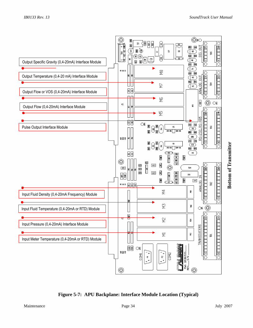
Figure 5-7: APU Backplane: Interface Module Location (Typical)
Output Specific Gravity (0,4-20mA) Interface Module
Output Temperature (0,4-20 mA) Interface Module
Output Flow or VOS (0,4-20mA) Interface Module
Output Flow (0,4-20mA) Interface Module
Input Pressure (0,4-20mA) Interface Module
Input Meter Temperature (0,4-20mA or RTD) Module
Input Fluid Density (0,4-20mA Frequency) Module
Pulse Output Interface Module
Input Fluid Temperature (0,4-20mA or RTD) Module

SoundTrack User Manual IB0133 Rev. 13
June 2012 Page 35 Troubleshooting and Diagnostics
6 TROUBLESHOOTING AND DIAGNOSTICS FOR THE ULTRASONICS
6.1 DiagnosticsThe SoundTrack Transmitter interfaces to external devices via a serial port or infrared port. TheSoundTrack uses the MODBUS protocol. Cameron provides PC (laptop) software to interface with thetransmitter via MODBUS (LEFMLink). Alternatively, the Caldon MODBUS manual can be used toselect the appropriate registers.
Note: Throughout, the remainder of this manual, values such as path SNR (Signal to Noise Ratio),gain, etc., are discussed as if the reader is using the Cameron provided software (LEFMLink),(MODBUS register addresses will not be mentioned, see the Modbus users manual).
For the ultrasonic signals, the most frequently used diagnostic information will be the following: Rejects (% Unused Data) Range 0 – 100%, normal operation, 0 – 5% Gain (Up/Down) Electronic amplification in dB required to process received ultrasonic signals.
Range 0 – 88dB, normal operation, 40 dB – 80 dB SNR (Signal-to-Noise-Ratio) Range 0 - 100
The SoundTrack performs the following automatic fault detection: The APU checks data quality of the ultrasonic signals and evaluates data against pre-set
thresholds. The data is evaluated based on SNR, cross-correlation tests and signal statistics. Occasionally data will be rejected; however, this will not influence the operation. If the
ultrasonic path continues to reject data, the meter will enter an "ALARM" status. The APU will output the current status through a digital output and MODBUS.
The meter status (based upon the path status) includes: "NORMAL" status – meter "ALARM" status – Acoustic path failure. Analog output set to minimum; computed relative
density is set to -1 and viscosity is set to -1000.

IB0133 Rev. 13 SoundTrack User Manual
Troubleshooting and Diagnostics Page 36 June 2012
6.2 Path Troubleshooting
The SoundTrack continuously checks the data quality of the acoustic path. Each time the ultrasonicsignal is sampled, the APU tests the signal as follows:
Verifies path’s SNR is higher than its threshold value. Correlates the Upstream Signal with the Downstream Signal to test for “cycle skipping”. The
APU rejects data that does not pass this correlation test. Verifies the statistics of the computed transit time and Delta T are acceptable.
6.2.1 Path Reject Status
When the path status indicates that the Reject Test is failed, it indicates that the percentage of data thathas been rejected has exceeded the SoundTrack’s thresholds. The following troubleshooting sequencecan be followed to pinpoint the root cause.
1. Verify that the pipeline (wafer) is full of liquid.2. Verify continuity for all cables.3. Check all APU power supply voltages. If the LED for any power supply is not lit on the front of
the APU card, then the fuse may be blown, or the power supply has failed. (See Section 5.3).4. Check Transmit LED on APU board. If transmit LED on the APU is not lit, then the APU may
need a configuration file, otherwise replace current APU board with a new APU board.5. Check the Acoustic Signal6. Check path gains (via MODBUS or Caldon Interface Software). If the path gains are high (85db
and higher), then the signals may be too weak to operate. Weak signals can be caused by any of thefollowing (listed from most likely to least likely)
Line is not full of liquid. Line pressure is too low for the vapor pressure Cable/wire from the meter to the transmitter is damaged Transducer coupling needs to be replaced (with grease couplants only) Transducer has failed
7. Determine Which Transducer Has Failed
The transmitter continuously operates each transducer individually in a pulse–echo mode. Pulse-echo means that a transducer transmits acoustic energy across the liquid, and receives the energyechoed off the opposing transducer. In pulse-echo mode, the transmitter then computes the gainfor both upstream and downstream transducers.
The gains for the upstream and the downstream pulse-echo tests are normally equal (±4 dB).However, a failed transducer due to wiring, coupling, etc., will show a higher gain (greater than4dB, typically). Using the direct acoustic path and the pulse-echo paths, follow these steps todetermine which transducer to evaluate:
1. Ensure that the direct path SNR is at least 30.2. Review the gains for the direct acoustic path (both upstream and downstream). The gains
should be between 40dB and 70dB. Upstream and downstream gain should nominallybe within 3 dB of each other.
3. Review the gains for each pulse-echo path (upstream and downstream). The transducerwith the higher gain should be investigated first.

SoundTrack User Manual IB0133 Rev. 13
June 2012 Page 37 Troubleshooting and Diagnostics
Note: There will be situations where the pulse-echo path gains are at the maximum(~88dB). If this is the case, investigate the cables and the transducers of bothtransducers.
If an acoustic signal does not exist (100% rejects), or if SNR has degraded significantly frominstallation, then follow checklist below:1. Verify the pipeline (wafer) is full of liquid.2. Check the transducer impedance. If the transducer impedance is less than 10 MΩ, then replace
transducer.
NOTE: If a meggar is used to test cables/transducers, DO NOT USE voltage over 250V. Do notuse MEGGER w/o Disconnecting Cable from Electronics!
3. Check the impedance of the transducer cable. If cable impedance is less than 10 MΩ, then replace/repair cable.
4. Check continuity of transducer cable. If transducer cable continuity impedance is infinite, thenrepair/replace cable.
5. If a signal is present, the ultrasonic transducer may need to be reseated, or the acoustic couplingmay need to be replaced. See Section 5.4.4.
6.3 Troubleshooting Acoustic SignalsBeing able to view and understand acoustic signals is essential when troubleshooting failed acousticpaths.
6.3.1 Oscilloscope Setup
To observe the waveform from a received transducer signal, connect an oscilloscope to the "Receive"test point (TP4) on the top edge of the APU card and connect the probe's ground to TP00 (ReferenceFigure 5-2). Next, connect the oscilloscope's "external trigger" to the "trigger" test point (TP3) on thetop edge of the APU card. An external trigger level of 2-3 volts is appropriate for most oscilloscopes.
6.3.2 Observed Waveform
With the oscilloscope set to 1 volt/division, and the timebase set to 2 microseconds / division, thetransducer signal waveform should be similar to that shown in Figure 6-1. Note that the time base delayof the oscilloscope should be set to approximately the expected transit time of the ultrasonic signal (SeeT-down from LEFMLink).
In troubleshooting an observed wave form, verify that the peak cycle of the wave form is ~3V.Preceding random noise should be nominally <0.2 Vpp.

IB0133 Rev. 13 SoundTrack User Manual
Troubleshooting and Diagnostics Page 38 June 2012
Figure 6-1: Example Transducer Signal Waveform
6.3.3 Selecting Transducer Signal Waveforms
Individual acoustic and echo path waveforms can be viewed by using the Control Selector Switches(Dip Switches) on the front edge of the APU (Reference Figure 5-2). Use Table 6-1 below to determinethe Dip Switch positions for the different paths.
Dip Switch 2 Dip Switch 3 Dip Switch 4 Dip Switch 5 Path Selected for OscilloscopeDown Up Down Up Down Up Down Up Transmitting Receiving
X X X X Path 1 Up Path 1 DownX X X X Path 1 Down Path 1 Up
X X X X Path 1 Up Path 1 UpX X X X Path 1 Down Path 1 Down
Table 6-1: Acoustic Transducer Selection
(Note: X indicates Switch Position)
All Dip Switches should be in the down position if the unit is reset or powered down and back up.The directions "Up" and "Down" used above are when viewing the top edge of the APU, as when it isinside the SoundTrack Electronics Cabinet.
-3
-2
-1
0
1
2
3
4
240 242 244 246 248 250 252 254 256 258 260
Time (microseconds)
Vo
lts
Peak Cycle ~ 3V
Triggering Cycle Typically 60 - 90% of Peak Cycle
Noise Preceding Ultrasonic
Signal Typicall < 0.2 Vpp

SoundTrack User Manual IB0133 Rev. 13
June 2012 Page 39 Troubleshooting and Diagnostics
Figure 6-2: Top Edge of APU Board (Side View)
Trigger TP3
Ground TP00
Receive Signal TP4
+150V (LED)
-12V (LED)
+5V (LED)
+12V (LED)
Reset
Control Selector
Switches
12
3
4
5
6
TRANSMIT (LED)
(switches shown down)

IB0133 Rev. 13 SoundTrack User Manual
Troubleshooting and Diagnostics Page 40 June 2012
6.4 Reprogramming the Transmitter
While it is not likely, there may be a time that the transmitter may need to be reprogrammed.This would typically occur when an APU Board has been replaced with an inventory item, notspecifically assigned to a given wafer. It is Cameron’s policy to provide a configuration file for eachwafer. This configuration file includes:
o Pipe Sizeo Transducer Frequencyo Acoustic Path Lengthso Calibration Constantso Alarm Settingso Analog Input/Output Scaling
The setup file is critical to the specific wafer’s performance.
1) Cameron maintains records and configuration files for all of its delivered meters. Thesimplest way to reprogram a transmitter is to use Caldon’s PC software (LEFMLink). Seethe LEFMLink Manual.
Once these steps are complete, the transmitter is reprogrammed.
The transmitter may also be reprogrammed through Modbus using a customer interface, however, it isnot recommended. Given that there are many registers to load, the process will be tedious and prone toerrors.
6.4.1 Modbus ID and Baud Rate
All Caldon transmitters are programmed with Modbus ID set to 1, Baud Rate at 9600 and in RTU SlaveMode. If the transmitter has been reprogrammed with a different setting and this setting is not known,simply set DIP Switch Number to 2 to up (TRUE) and toggle the reset switch. Resetting the transmitterin this mode forces the transmitter to operate with its default communication settings (Slave Address =1, Baud Rate = 9600, RTU Slave).
When the system is restarted with DIP Switch 2 in the Up position the transmitter WILL NOTTRANSMIT (No LED 5) without first receiving a setup.

SoundTrack User Manual IB0133 Rev. 13
June 2012 Page 41 Recommended Spare Parts
7 RECOMMENDED SPARE PARTS
7.1 Domestic (US and Canada)
Qty: 1 F1 - Littelfuse 274.125 – 125mA radial lead fuseQty: 1 F2 - Littelfuse 27201.5 – 1500mA radial lead fuseQty: 2 F7/F10 - Littelfuse 274.5 – 500mA radial lead fusesQty: 1 Serial Communications Kit (Includes LEFMLink Software)Qty: 1 Transducer (appropriate frequency)Qty: 1 Transducer Grease (small tube)Qty: 1 RTD Interface Module (Input)Qty: 1 0-20 mA Interface Module (Output)
7.2 International
Same as above, except includes:
Qty: 1 APU Board
Note: The APU Board contains electrolytic capacitors. In order to maintain proper operation ofthese components they must have a functional test at least once every five (5) years. ContactCameron's Measurement Systems division for the specifics of the functional test.

IB0133 Rev. 13 SoundTrack User Manual
Recommended Spare Parts Page 42 June 2012

SoundTrack User Manual IB0133 Rev. 13
WARRANTY - LIMITATION OF LIABILITY: Seller warrants only title to the products, software,supplies and materials and that, except as to software, the same are free from defects inworkmanship and materials for a period of one (1) year from the date of delivery. Seller does notwarranty that software is free from error or that software will run in an uninterrupted fashion.Seller provides all software "as is". THERE ARE NO WARRANTIES, EXPRESS OR IMPLIED,OF MERCHANTABILITY, FITNESS OR OTHERWISE WHICH EXTEND BEYOND THOSESTATED IN THE IMMEDIATELY PRECEDING SENTENCE. Seller's liability and Buyer'sexclusive remedy in any case of action (whether in contract, tort, breach of warranty orotherwise) arising out of the sale or use of any products, software, supplies, or materials isexpressly limited to the replacement of such products, software, supplies, or materials on theirreturn to Seller or, at Seller's option, to the allowance to the customer of credit for the cost ofsuch items. In no event shall Seller be liable for special, incidental, indirect, punitive orconsequential damages. Seller does not warrant in any way products, software, supplies andmaterials not manufactured by Seller, and such will be sold only with the warranties that aregiven by the manufacturer thereof. Seller will pass only through to its purchaser of such itemsthe warranty granted to it by the manufacturer.

CaldonUltrasonics
Customer Service & Technical Support
1000 McClaren Woods DriveCoraopolis, PA 15108 USATel 724-273-9300
The ultrasonic measurementgroup of Cameron
www.c-a-m.com