california trimmer
TRANSCRIPT

CALIFORNIA TRIMMER
MOWER MAINTENANCE MANUAL

California Trimmer Mower Maintenance Manual
2

California Trimmer Mower Maintenance Manual
3
Table of Contents
Section 1: General Information Page
Handle Assembly Instructions 4
Maintenance – All Models 6
Oil Change Procedures – All Models 9
Height Adjustment – All Models 10
Catcher and Bale Adjustment – All Models 12
Section 2: Home Owner Model Page
Clutch Adjustment 14
Reel Adjustment 16
Roller Adjustment 18
Roller Assembly 20
Trouble Shooting
“Reel won’t turn” 22
“Mower won’t propel” 23
Parts List and Mower Schematics 24
Section 3: Commercial Models Page
Clutch 27
Reel Adjustment 30
Roller Adjustment 33
Drive Shaft Disassembly 35
Drive Shaft Assembly 36
Roller Assembly 42
Trouble Shooting
“Reel won’t turn” 46
“Mower won’t propel” 47
Parts List and Mower Schematics 48
California Trimmer Mower Maintenance Manual
4
Handle Assembly Instructions
Home Owner Model
Tools Required: 2 1/2” Wrenches 2 7/16” Wrenches
1 3/8” Wrench 1 Flat-Blade Screw Driver
1 Pliers w/cutters
To determine Left or Right, position yourself in the operator’s position behind the mower.
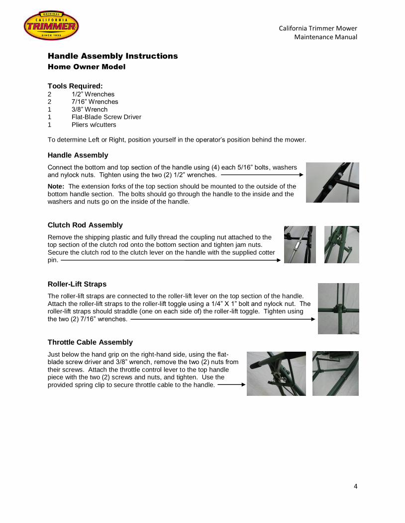
Handle Assembly
Connect the bottom and top section of the handle using (4) each 5/16” bolts, washers and nylock nuts. Tighten using the two (2) 1/2” wrenches.
Note: The extension forks of the top section should be mounted to the outside of the
bottom handle section. The bolts should go through the handle to the inside and the washers and nuts go on the inside of the handle.
Clutch Rod Assembly
Remove the shipping plastic and fully thread the coupling nut attached to the top section of the clutch rod onto the bottom section and tighten jam nuts.
Secure the clutch rod to the clutch lever on the handle with the supplied cotter pin.
Roller-Lift Straps
The roller-lift straps are connected to the roller-lift lever on the top section of the handle.
Attach the roller-lift straps to the roller-lift toggle using a 1/4” X 1” bolt and nylock nut. The roller-lift straps should straddle (one on each side of) the roller-lift toggle. Tighten using
the two (2) 7/16” wrenches.
Throttle Cable Assembly
Just below the hand grip on the right-hand side, using the flat-blade screw driver and 3/8” wrench, remove the two (2) nuts from
their screws. Attach the throttle control lever to the top handle piece with the two (2) screws and nuts, and tighten. Use the
provided spring clip to secure throttle cable to the handle.

California Trimmer Mower Maintenance Manual
5
Handle Assembly Instructions
Heavy Duty & Commercial Models
Tools Required: 2 1/2” Wrenches 1 7/16” Wrenches
1 3/8” Wrench 1 Flat-Blade Screw Driver
1 Pliers w/cutters
To determine Left or Right, position yourself in the operator’s position behind the mower.
Handle Assembly
Connect the bottom and top section of the handle using (4) each 5/16” bolts, washers
and nylock nuts. Tighten using the two (2) 1/2” wrenches.
Note: The extension forks of the top section should be mounted to the outside of the
bottom handle section. The bolts should go through the handle to the inside and the
washers and nuts go on the inside of the handle.
Clutch Rod Assembly
Remove the shipping plastic and fully thread the coupling nut attached to the top section of the clutch rod onto the bottom section and tighten jam nuts.
Secure the clutch rod to the clutch lever on the handle with the supplied cotter pin.
Roller-Lift Rod
The roller-lift rod is connected to the roller-lift lever on the top section of the handle. Insert the bottom end of the roller-lift rod into the roller-lift toggle, secure roller-lift rod to
roller-lift toggle with a cotter pin.
Throttle Cable Assembly
Just below the hand grip on the right-hand side, using the flat-blade screw driver and 3/8” wrench, remove the two (2) nuts from their
screws. Attach the throttle control lever to the top handle piece with the two (2) screws and nuts, and tighten. Use the provided spring
clip to secure throttle cable to the handle.

California Trimmer Mower Maintenance Manual
6
Mower Maintenance
Heavy Duty & Commercial Models
6 4 1 2 4 6
6 3 5 6 3

California Trimmer Mower Maintenance Manual
7
Mower Maintenance
Heavy Duty & Commercial Models
Commercial Use – Daily Inspection
1. Check Engine oil level. The oil should be filled to the engine specifications (see engine
owner’s manual)
2. Check air cleaner. Some Honda engines have an oil bath filter. Oil should be added to
maintain optimum level. Inspect sponge filter for debris (dirt, grass etc.). Briggs engines
have a dry filter. Inspect for debris (dirt, grass etc.).
3. Check engine and reel chain tension, adjust if necessary. All chains should have about a
1/4” of play. Loosen chain-tensioner bolt, adjust tensioner setting chain to desired
tension and re-tighten bolt. Check roller chain tension once each week. To tighter roller
chain raise roller aligning the roller shaft parallel to the drive shaft. This puts the roller at
the furthest point of movement.
4. Grease reel grease fittings (zerk fittings).
5. Grease clutch forks. Put grease on shaft between the ends of the forks.
6. Grease zerk fittings on front and rear wheels. Steady rest, center drive shaft support
bracket, should be filled once a month.
7. Lube chain with engine oil. Use a paint brush to apply oil to chain. Momentarily run
machine to spin off excess oil before use.
Non-Commercial Use Only
1. Follow the same procedures listed above after every eight hours of use.

California Trimmer Mower Maintenance Manual
8
Notes
______________________________________________________________________________
______________________________________________________________________________
______________________________________________________________________________
______________________________________________________________________________
______________________________________________________________________________
______________________________________________________________________________
______________________________________________________________________________
______________________________________________________________________________
______________________________________________________________________________
______________________________________________________________________________
______________________________________________________________________________
______________________________________________________________________________
______________________________________________________________________________
______________________________________________________________________________
______________________________________________________________________________
______________________________________________________________________________
______________________________________________________________________________
______________________________________________________________________________
______________________________________________________________________________
______________________________________________________________________________
______________________________________________________________________________

California Trimmer Mower Maintenance Manual
9
Oil Change Procedure
All models
Preparation for mowers with oil bath air filters.
Note: This method of oil change should be done when the gas tank is low on fuel. If the fuel tank is full,
gas could leak around the gas cap.
1. Undo wing nut and remove oil bath filter reservoir, both top and bottom pieces.
Note:
2. Remove carefully, check for the reservoir gasket, which may stick to the bottom section of the oil
reservoir.
3. The GX series engine has two oil plugs, one in the front and one in the back, for draining oil from the engine. However, the position of the engine on the frame does not offer easy access and can cause the old oil to pour onto the mower, requiring extra clean-up time. It is easier to remove the oil-fill plug. Tip the mower forward and pour oil into a can or plastic container.

California Trimmer Mower Maintenance Manual
10
Height Adjustment
All models
Two different ranges of height adjustments are available. The higher range is achieved with the “caster
bracket” (no. 1) in the bottom hole (as shown). The lower range is achieved with the “caster bracket” (no. 1) in the top hole.
With the “caster bracket” (no.1) in the lower hole, the “height adjustment lever” (no. 2) will utilize the top 4 to 5 holes of the “quadrant” (no. 3).
With the “caster bracket” (no. 1) in the top hole, the “height adjustment lever” (no. 2) will utilize the bottom
4 to 5 holes of the “quadrant” (no. 3). In either height range, moving the “height adjustment lever” (no. 2) towards the front of the mower will
raise the height in small increments. Moving the “height adjustment lever” (no. 2) towards the back of the mower will lower the height in small increments.
1
3 2 4 5 6
To change the range setting, take the “height adjustment lever” (no. 2) out of the holes of the “quadrant” (no. 3) and move it in the direction of the change. Back if the “caster bracket” (no.1) is being moved to
the top hole or forward if the “caster bracket” (no.1) is being moved to the bottom hole. Loosen the “caster wheel nut” (no. 6).
Remove the nut on the “tie rod” (no. 4), slide the “tie rod” (no. 4) out, being careful not to lose the washer between the “adjuster bracket” (no. 5) and the frame (washer not shown). Slide the “tie rod” (no. 4)
through the desired hole of the side plate, “caster bracket” (no. 1), and the other side plate. Place the washer (not shown) on the “tie rod” (no. 4) between the frame and “adjuster bracket (no. 5). Install the nut on the “tie rod” (no. 4). Do not over tighten this nut, the height adjuster pivots at this point. Tighten the
“caster wheel nut” (no. 6).

California Trimmer Mower Maintenance Manual
11
Catcher and Bale Adjustment
All models
The “V” of the catcher bale is offset to one side, making one side shorter than the other. On 20 and 25 commercial mowers the short side goes to the left, as shown. On the Home Owner mower the short side
goes to the right.
The catcher has three “bale” holes on each side to accommodate the bale at various height settings. After setting mower to the desired height, see height adjustment, put the bale in the holes that positions the catcher as level to the ground as possible.
Bale holes
Short leg “V”
After determining the best “bale holes”, attach the bale to the catcher using a washer and cotter pin on each side.

California Trimmer Mower Maintenance Manual
12
Notes
______________________________________________________________________________
______________________________________________________________________________
______________________________________________________________________________
______________________________________________________________________________
______________________________________________________________________________
______________________________________________________________________________
______________________________________________________________________________
______________________________________________________________________________
______________________________________________________________________________
______________________________________________________________________________
______________________________________________________________________________
______________________________________________________________________________
______________________________________________________________________________
______________________________________________________________________________
______________________________________________________________________________
______________________________________________________________________________
______________________________________________________________________________
______________________________________________________________________________
______________________________________________________________________________
______________________________________________________________________________
______________________________________________________________________________
California Trimmer Mower Maintenance Manual
13
Home Owner Model
Clutch Adjustment
Tools Required: 2 1/2” Wrenches 1 1/8” Allen wrench
CAUTION:
ALL ADJUSTMENT MUST BE MADE WITH THE ENGINE TURNED OFF.
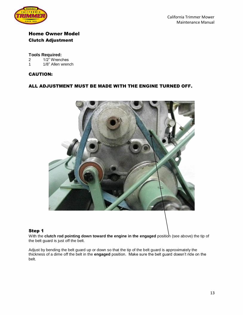
Step 1
With the clutch rod pointing down toward the engine in the engaged position (see above) the tip of
the belt guard is just off the belt.
Adjust by bending the belt guard up or down so that the tip of the belt guard is approximately the thickness of a dime off the belt in the engaged position. Make sure the belt guard doesn’t ride on the
belt.

California Trimmer Mower Maintenance Manual
14
Home Owner Model
Clutch Adjustment
BRACKET SWIVEL BEARING BOTTOM PULLEY
Step 2
With the clutch rod pointing up in the disengaged position (see above) make sure the idler bearing does
not ride on the bottom pulley. The idler bearing should be within one quarter (1/4) of an inch from the bottom pulley. The belt release bracket should be above parallel to the frame, thus creating a slight bend in the belt.
Adjustments to the idler is made in the engaged position by loosening the set screw in the swivel and
sliding the clutch rod up or down. Reset the set screw in the swivel when adjustment is complete.
Adjustments to the release bracket are done after the belt bearing is positioned correctly. In the disengaged position, loosen the nut on the bearing and position the belt release bracket above parallel to
the frame. Retighten the nut when adjustment is complete.

California Trimmer Mower Maintenance Manual
15
Home Owner Model
Cutter Bar to Reel Adjustment
Tools Required: 1 Adjustable Wrench or 1/4” Open-end Wrench
CAUTION:
ALL ADJUSTMENTS MUST BE MADE WITH THE ENGINE TURNED OFF.
The reel on the Home Owner model is fixed and stationary to the frame. The cutter bar is adjusted to the
reel. The cutter bar adjusting screws raise and lower the cutter bar in relation to the reel.
Step 1 Disengage the clutch, as shown below, before adjusting the cutter bar.
Step 2 Turn one adjusting screw in small increments until the cutter bar touches the reel. Turn the reel with one hand. Rest the palm of one hand on the caster bracket and pull the blade on the reel with the fingers of
that hand. The reel should move about the distance of the space between the blades. As the reel is turned it will make the sound of metal scraping.

California Trimmer Mower Maintenance Manual
16
Home Owner Model
Cutter Bar to Reel Adjustment – (Continued)
Step 3 Repeat the above process with the opposite adjusting screw.
Step 4 Slide a piece of thin paper, such as a page from a phone book or newspaper, at small intervals, all the way across the cutter bar to test for proper adjustment. When adjusted properly the paper will be cut
cleanly and evenly across the entire width of the mower.

California Trimmer Mower Maintenance Manual
17
Home Owner Model
Roller Adjustment Procedures
Tools Required: 1 5/32” Allen Wrench 1 7/16” Wrench 1 Screw Driver
CAUTION:
ALL ADJUSTMENTS MUST BE MADE WITH THE ENGINE TURNED OFF.
Step 1 Loosen roller “U” Bolts and set screws on both sides of the drive roller. This will loosen the drive roller on the yoke.
Step 2 Pull the drive roller back, tensioning the chain taut. Make sure the drive roller is in the furthest position from the drive shaft. If the drive roller is not in the furthest most position, the chain will become relaxed.

California Trimmer Mower Maintenance Manual
18
Home Owner Model
Roller Adjustment Procedures – (Continued)
To Check Move the drive roller up, past the furthest most position and the drive chain will become slack on top. Move the drive roller down, past the furthest most position and the chain will become slack on the bottom.
Make sure the bolt heads on the sprocket clear the yoke when it spins. Tighten the “U” Bolt and set screw on the right side.
Step 3 With the chain taught, in the furthest most position from the drive shaft, make sure the drive roller is parallel to the back cross piece of the yoke. Tighten the left “U” Bolt and set screw on the clamp.

California Trimmer Mower Maintenance Manual
19
Home Owner Model
Roller Assembly Procedures
Tools Required: 1 1/2” Wrench One end plate of the roller has three (3) holes and the other end plate has six (6) holes.
Step 1 Starting with the end that has three (3) holes, bolt the bearing holder and bearing, using the bolts, lock washers and washers. Do not tighten. Repeat on the other end.
Step 2 Slide the roller shaft into the roller from the six (6) hole side. This will align the bearing holders. Tighten
the bearing holders on both end plates.

California Trimmer Mower Maintenance Manual
20
Home Owner Model
Roller Assembly Procedures – (Continued)
Step 3 Place the sprocket spacers over the remaining three (3) holes.
Install a “30 Tooth” sprocket using the bolts, lock washers and washers. Try to center the sprocket as much as possible.
Make sure the roller spins freely. If prior to installation of the “30 Tooth” sprocket the roller spun freely,
but now does not, add a washer under each of the spacers.

California Trimmer Mower Maintenance Manual
21
Home Owner Model – Trouble Shooting
“Reel doesn’t turn”
TURN OFF ENGINE
DISENGAGE
CLUTCH
DOES REEL TURN
FREELY BY HAND
YES
NO ADJUST REEL SEE
INSTRUCTIONS
REMOVE CHAIN
GUARDS
START ENGINE &
ENGAGE CLUTCH
IS ENGINE PULLEY
TURNING?
YES
NO
REPLACE SET SCREWS AND/OR
KEY. SEE NOTE 2
IS BELT TURNING?
YES
IS BOTTOM PULLEY
TURNING?
YES
NO
REPLACE BELT AND/OR PULLEY.
SEE NOTE 2
NO
REPLACE SET SCREWS OR PULLEY.
SEE NOTE 2
IS THE 8 TOOTH SPROCKET ON
JACKSHAFT TURNING?
NO REPLACE SET SCREWS. SEE
NOTE 2

California Trimmer Mower Maintenance Manual
22
Home Owner Model – Trouble Shooting
“Reel doesn’t turn” – (Continued)
NOTE 1: LOOK AT SHAFT INSIDE 17 TOOTH OUSIDE SPROCKET.
NOTE 2: SHUT OFF ENGINE BEFORE ADJUSTING.
IS THE CHAIN
TURNING?
YES
YES
IS DRIVESHAFT TURNING? SEE
NOTE 1
YES
IS 17 TOOTH SPROCKETS
TURNING?
REPLACE SET SCREWS. SEE
NOTE 2
YES
NO
NO
YES
NO
NO
NO
REPLACE 8 TOOTH SPROCKET. SEE
NOTE 2
REPLACE DRIVESHAFT. SEE
NOTE 2
IS CHAIN TURNING?
YES
IS FRONT SPROCKET SPINNING ON REEL
SHAFT?
REPLACE 17 TOOTH SPROCKET.
SEE NOTE 2
CALL CALIFORNIA TRIMMER OR VISIT
WWW.CALTRIMMER.COM
REPLACE SET SCREWS. SEE
NOTE 2

California Trimmer Mower Maintenance Manual
23
Home Owner Model – Trouble Shooting
“Mower won’t propel itself”
TURN OFF ENGINE
DISENGAGE
CLUTCH
DOES REEL TURN
FREELY BY HAND
YES
NO ADJUST REEL SEE
INSTRUCTIONS
REMOVE CHAIN
GUARDS
START ENGINE &
ENGAGE CLUTCH
IS ENGINE PULLEY
TURNING?
YES
NO
REPLACE SET SCREWS AND/OR
KEY. SEE NOTE 2
IS BELT TURNING?
YES
IS BOTTOM PULLEY
TURNING?
YES
NO
REPLACE BELT AND/OR PULLEY.
SEE NOTE 2
NO
REPLACE SET SCREWS OR PULLEY.
SEE NOTE 2
IS THE 8 TOOTH SPROCKET ON
JACKSHAFT TURNING?
NO REPLACE SET SCREWS. SEE
NOTE 2

California Trimmer Mower Maintenance Manual
24
Home Owner Model – Trouble Shooting
“Mower won’t propel itself” – (Continued)
NOTE 1: LOOK AT SHAFT INSIDE 17 TOOTH OUSIDE SPROCKET. NOTE 2: SHUT OFF ENGINE BEFORE ADJUSTING.
IS THE CHAIN
TURNING?
YES
IS DRIVESHAFT TURNING? SEE
NOTE 1
YES
IS 8 TOOTH SPROCKET
TURNING?
REPLACE SET SCREWS. SEE
NOTE 2
YES
NO
YES
NO
NO
NO
NO
REPLACE 8 TOOTH SPROCKET. SEE
NOTE 2
REPLACE DRIVESHAFT. SEE
NOTE 2
IS CHAIN TURNING?
YES
IS ROLLER SPINNING
REPLACE 8 TOOTH SPROCKET. SEE
NOTE 2
DISASSEMBLE ROLLER TO DETERMINE
PROBLEM. SEE NOTE 2
ADJUST ROLLER LIFT
CHAIN. SEE NOTE 2

California Trimmer Mower Maintenance Manual
25
Heavy Duty & Commercial
Clutch Adjustment
Tools Required: 2 1/2” Wrenches
Pre-Adjustment Preparation
The air filters on some engines have an oil bath air filter and must be removed prior to tipping the mover forward to adjust the clutch forks.
Step 1 Tip the mower forward up onto the front part of the frame so that the handle is resting on a table or work
bench. Or support the fuel tank with a block of wood or stand like pictured below.

California Trimmer Mower Maintenance Manual
26
Heavy Duty & Commercial
Clutch Adjustment – (Continued)
Clutch Adjustment Bolt
Part # 25321
The clutch spring is held in place by two clutch forks that are connected by the clutch adjustment bolt.
The clutch adjusting bolt has two nuts set together that hold the clutch forks and spring in position once it
has been adjusted to the proper tension. The inner nut is for adjusting the tension of the spring and the
outer jam nut, when tightened against the inner nut, secures the desired tension of the spring.
Adjusting the Clutch Spring Tension
Step 1 Disengage the clutch. This will allow the drive sprocket to move slightly to the right and to the left on the
drive shaft.
Step 2 Use one 1/2” wrench to hold the inner nut and the second 1/2” wrench to loosen the outer jam nut. Once
the outer jam nut is loosened, the inner nut can be turned clockwise to; compress the clutch spring, widening the gap between the clutch pad and sprocket but decreasing the tension on the clutch, or counter clockwise to; lessen the tension on the spring, decreasing the gap between the clutch pad and
sprocket and increase the tension on the clutch.

California Trimmer Mower Maintenance Manual
27
Heavy Duty & Commercial
Clutch Adjustment – (Continued)
The proper spacing for the clutch is about the thickness or a nickel or quarter. Press the drive sprocket
over toward the large fork. The proper spacing can be gauged between the clutch lining and the drive
sprocket.
Step 3 When proper clearance has been achieved retighten outer jam nut.

California Trimmer Mower Maintenance Manual
28
Heavy Duty & Commercial
Reel Adjustment
Tools Required: 1 Hammer 1 Screw Driver or Metal Rod/Punch, approx. 12” long 2 7/16” Wrenches
To determine Left or Right, position yourself in the operator’s position behind the mower.
The reel bearing holders are off centered and mounted to the side plates of the frame with the reel-shaft
hole toward the front to the mower at the 10 o’clock position on the left-hand side and the 2 o’clock position on the right-hand side or the mower.
Step 1
Three bolts and the clamp ring secure the reel bearing holders to the frame. To make adjustments, first
loosen all the bolts approximately 1/4 of a turn. The left-side clamp ring has three threaded holes. Only
the bolts are loosened on the left side. On the right-side the unthreaded clamp ring is secured with three
sets of bolts and nuts.

California Trimmer Mower Maintenance Manual
29
Heavy Duty & Commercial
Reel Adjustment – (Continued)
Step 2 There two shoulders or “notch” studs on each reel bearing holder. Place the screw driver or metal punch
on the notch stud and using the hammer tap the studs down in the front on one side, then the other. This moves the reel bearing holder, moving the reel blades down toward the cutter bar. The blades passing over the cutter bar will make a whooshing or metal-to-metal scraping sound. If the reel blades are too
close to the cutter bar, and the reel will not spin, place the screw driver or metal on the “notch” studs on the back side of the bearing holder closest to the grass shield, and using a hammer tap the bearing
holders up and then repeat the process to lower to desired position. This may take several attempts to get the reel into the desired position.

California Trimmer Mower Maintenance Manual
30
Heavy Duty & Commercial
Reel Adjustment – (Continued)
Step 3
Take a piece of thin paper, such as from a phone book or newspaper. Place a small part of the paper between the cutter bar and blade. Carefully turn the reel downward. If the blade and cutter bar are
aligned properly, the paper will be cut evenly, across the length or the cutter bar.
Step 4
Caution: Do not completely tighten nuts and bolts. This could cause the cutter bar and reel to come out
of adjustment.
When the reel is set in the desired position, begin tightening all nuts and bolts. Do not completely tighten the nuts and bolts as this could cause the reel and cutter bar to come out of adjustment. Start
by snuggly securing all nuts and bolts, in a consecutive manor, gradually tighten each nut and bolt in successive rotation until all are tight, securing reel gearing holders in the desired positions.
Step 5
After all nuts and bolts have been tightened, recheck the setting with a piece of thin paper as described above. Sometimes during the tightening process, the reel can be shifted up, down or away from the
cutter bar. If necessary repeat the process.

California Trimmer Mower Maintenance Manual
31
Heavy Duty & Commercial
Roller Adjustment Procedures
Tools Required: 1 1/8” Allen Wrench
1 Screw Driver 2 7/16” Wrenches
CAUTION:
ALL ADJUSTMENTS MUST BE MADE WITH THE ENGINE TURNED OFF.
Step 1 Loosen roller “U” Bolts and set screws on both sides of the drive roller. This will loosen the drive roller on
the yoke.
Step 2 Pull the drive roller back, tensioning the chain taut. Make sure the drive roller is in the furthest position from the drive shaft. If the drive roller is not in the furthest most position, the chain will become relaxed.

California Trimmer Mower Maintenance Manual
32
Heavy Duty & Commercial
Roller Adjustment Procedures – (Continued)
To Check Move the drive roller up, past the furthest most position and the chain will become slack on top. Move the drive roller down, past the furthest most position and the chain will become slack on the bottom. Make
sure the bolt heads on the sprocket clear the yoke when it spins. Tighten the “U” Bolt and set screw on the right side.
Step 3 With the chain taught, in the furthest most position from the drive shaft, make sure the drive roller is parallel to the back cross piece of the yoke. Tighten the left “U” Bolt and set screw on the clamp.

California Trimmer Mower Maintenance Manual
33
Heavy Duty & Commercial
Drive Shaft Disassembly
Tools Required: 1 5/32” Allen Wrench 1 Pulley Puller 1 Needle Nose Pliers 1 Hammer
2 1/2” Wrenches 1 Spring Compression Tool
Unbolt both chain guards and remove. Remove all three (3) chains by removing their master links.
Remove the two (2) roller springs. Disconnect the clutch rod from the clutch fork. Remove the two (2) clutch forks and clutch adjustment bolt.
Unbolt the steady rest. Remove the two (2) set screws from the 17 tooth outer sprocket.
Unbolt the bearing holders from the frame on both sides. Remove the drive shaft assembly from the mower frame.
Using a pulley Puller, remove the bearing holder from the right side. NOTE: Do not pull the bearing holder by it’s’ “ears”. This may cause them to break off. Remove the wheel(s) and spacer(s).
Using a Pulley Puller, remove the bearing holder from the other side. NOTE: Do not pull the bearing holder by the “ears”. This may cause them to break off.
Remove the wheel(s) and spacer(s). Remove the set screws from the wheel set collar. Slide the set collar off. You may need to tap the set collar with a hammer to remove it. Be careful not to
hit the drive shaft, this may cause damage to the drive shaft. Remove the set screws from the roller drive sprocket and remove. Like the set collar you may need to
tap the sprocket with a hammer to remove it. Be careful not to hit the drive shaft, this may cause damage to the drive shaft.
Slide the steady rest and small hard washer off. Slide the spring compression tool on the shaft until it is touching the set collar in its extended length and tighten it in place. Now loosen the set screws on the set collar and relieve tension on the spring.
Remove the remaining parts.

California Trimmer Mower Maintenance Manual
34
Heavy Duty & Commercial
Drive Shaft Assembly
Tools Required: 1 5/32” Allen Wrench 1 Bearing Setting Tool 1 Needle Nose Pliers 1 Hammer
2 1/2” Wrenches 1 Spring Compression Tool
Secure the drive shaft, either by inserting the short end of the drive shaft into a hole in your work bench or secure in a vice. Take care not to dent or mar the surface of the drive shaft.
Step 1
Make sure the drive shaft clutch plate is clean and dry.
The clutch lining has a solid black rubber side and a belted side.
Step 2
Place the lining with the solid black rubber side facing down, on the clutch plate of the drive shaft, and the belted side facing up.

California Trimmer Mower Maintenance Manual
35
Heavy Duty & Commercial
Drive Shaft Assembly – (Continued)
Step 3
Install the 39 tooth sprocket. Make sure that it is clean and dry prior to installation. The 39 tooth sprocket should spin freely on the drive shaft. You may need to install a small amount of grease to the inside of the oilite bushing. If you do add grease to the bushing make sure that excess does not get on the clutch
lining.
If the 39 tooth sprocket does not spin freely, check the drive shaft and the bushing for galling, or roughness.
Step 4
Install one small hard washer, the clutch spacer and the large hard washer. The large hard washer has a rounded outer edge on one side and a square outer edge on the other. Be sure to put the rounded
edge towards the 39 tooth sprocket to avoid excessive wear to the clutch fork.
California Trimmer Mower Maintenance Manual
36
Heavy Duty & Commercial
Drive Shaft Assembly – (Continued)
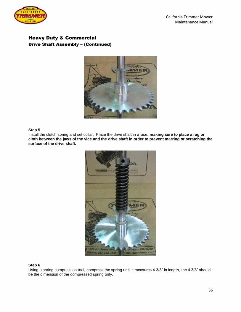
Step 5
Install the clutch spring and set collar. Place the drive shaft in a vise, making sure to place a rag or cloth between the jaws of the vice and the drive shaft in order to prevent marring or scratching the
surface of the drive shaft.
Step 6
Using a spring compression tool, compress the spring until it measures 4 3/8” in length, the 4 3/8” should be the dimension of the compressed spring only.

California Trimmer Mower Maintenance Manual
37
Heavy Duty & Commercial
Drive Shaft Assembly – (Continued)
To compress, slide the spring compression tool, in it’s contracted length, onto the drive shaft and tighten its two (2) set screws. Turn the bottom part of the spring compression tool until the desired measurement of the spring is achieved. Tighten the two (2) set screws on the set collar. Be sure to use a liquid thread lock on the set screws. Slowly loosen the tension on the spring compression tool by turning the
bottom, making sure the collar is holding securely in place. Loosen the set screws on the spring compression tool and remove from drive shaft. Lightly file the two (2) indentations on the drive shaft, left
by the set screws, if needed. Check the length of the spring to make sure the collar stayed in place. Step 7
On the shaft closest to the plate, install one wheel with the zerk fitting in the up position and grease the wheel. Install two (2) wheel spacers. Install the second wheel with the zerk fitting in the up position. Lay
the bearing and holder on the wheel against the shaft. If the shaft protrudes higher than the bearing, add additional shims until the top of the shaft is flush with the top on the bearing.
Install the bearing and holder with a driver. Make sure that the inner face of the bearing is not damaged
during installation. The bearing and wheels should spin freely.

California Trimmer Mower Maintenance Manual
38
Heavy Duty & Commercial
Drive Shaft Assembly – (Continued)
Step 8
Install the second small hard washer, steady rest, sprocket and set collar, as shown, on the other side of
the shaft. Put the rounded edge of the hard washer towards the steady rest. Leave the two (2) set screws on the sprocket loose in order to align the sprocket with the roller sprocket after the drive shaft
assembly has been installed in the mower.
Leave the two (2) set screws on the set collar loose until after the wheels have been installed.
Install the steady rest as shown (grease zerk facing down)
Step 9
Install the first wheel on this side with the zerk fitting facing the spring. Install as many wheel spacers or
shims as you did during the installation of the first set of wheels on the other side to ensure even placement of the wheels.
Install the second wheel with the zerk fitting facing the end of the drive shaft. Install the second bearing and holder with a driver as before, making sure not to damage the bearing.
Step 10
Grease the remaining three (3) wheels and steady rest.

California Trimmer Mower Maintenance Manual
39
Heavy Duty & Commercial
Drive Shaft Assembly – (Continued)
Step 11
Install the assembled drive shaft into the mower frame.
Bolt the bearing holder to the frame, on the left-side, or the clutch side of the drive shaft. Bolt the bearing holder to the frame on the other side.
Tap the end of the drive shaft to ensure it is seated completely in the left-side bearing holder. Slide both wheels and set collar over, against the bearing holder and tighten the two (2) set screws. Align the roller drive sprocket with the roller sprocket and tighten the two (2) set screws, be sure that one
of the set screws is tightening on the flat surface on the drive shaft. Install the roller chain and
roller springs. Install the 17 tooth sprocket and tighten the two (2) set screws, be sure that one of the set screws is tightening into the dimple on the drive shaft. Install chain and chain guard.
Install the engine chain and chain guard. Install the two (2) clutch forks and clutch adjustment bolt. Attach the clutch rod to the clutch fork.
Adjust the clutch. (See Clutch Adjustment on Page 28)

California Trimmer Mower Maintenance Manual
40
Heavy Duty & Commercial
Roller Assembly
Tools Required: 1 Bearing Driver 1 Hammer
1 1/2” Wrenches Step 1
Install one bearing holder with the bearing on one side of the roller shaft.
One end plate on the roller is set deeper inside the roller than the other. Step 2
Install roller shaft with the bearing holder on the plate that is set deeper. Use bolts, locks washers and
washers. Do not tighten at this time.
Step 3
Install a bearing holder with bearing on opposite end of the roller.

California Trimmer Mower Maintenance Manual
41
Heavy Duty & Commercial
Roller Assembly – (Continued)
Step 4
Install bolts, lock washers and washers. Tighten the bolts on both ends at this time.
Make sure the roller spins freely. If the roller does not spin freely one or both of the bearings may be
“locked” up on the shoulder of the roller shaft. Using a hammer, tap one or both sides of the roller shaft until the roller spins freely. Step 5
Place the sprocket spacer over the remaining three holes.
Step 6
Install the 30 tooth sprocket using bolts, lock washer and washers. Try the center the sprocket as much as possible.

California Trimmer Mower Maintenance Manual
42
Notes
______________________________________________________________________________
______________________________________________________________________________
______________________________________________________________________________
______________________________________________________________________________
______________________________________________________________________________
______________________________________________________________________________
______________________________________________________________________________
______________________________________________________________________________
______________________________________________________________________________
______________________________________________________________________________
______________________________________________________________________________
______________________________________________________________________________
______________________________________________________________________________
______________________________________________________________________________
______________________________________________________________________________
______________________________________________________________________________
______________________________________________________________________________
______________________________________________________________________________
______________________________________________________________________________
______________________________________________________________________________
______________________________________________________________________________

California Trimmer Mower Maintenance Manual
43
Heavy Duty & Commercial – Trouble Shooting
“Reel doesn’t turn”
TURN OFF ENGINE
DISENGAGE
CLUTCH
DOES REEL TURN
FREELY BY HAND
YES
NO ADJUST REEL SEE
INSTRUCTIONS
REMOVE CHAIN
GUARDS
START ENGINE &
ENGAGE CLUTCH
IS ENGINE SPROCKET
TURNING?
YES
NO
REPLACE SET SCREWS. SEE
NOTE 2
IS CHAIN TURNING?
YES
IS BOTTOM 39 TOOTH SPROCKET
TURNING?
YES
NO
REPLACE ENGINE SPROCKET. SEE
NOTE 2
NO
REPLACE SPROCKET. SEE
NOTE 2
IS THE DRIVE SHAFT TURNING?
SEE NOTE 1.
NO #1
ADJUST CLUTCH.
SEE INSTRUCTIONS
NO #2 DISASSEMBLE THE DRIVE SHAFT TO DETERMINE THE
PROBLEM

California Trimmer Mower Maintenance Manual
44
Heavy Duty & Commercial – Trouble Shooting
“Reel doesn’t turn” – (Continued)
NOTE 1: LOOK AT SHAFT INSIDE 17 TOOTH OUSIDE SPROCKET.
NOTE 2: SHUT OFF ENGINE BEFORE ADJUSTING.
IS THE 17 TOOTH SPROCKET
TURNING?
YES
YES
IS CHAIN TURNING? NO
NO REPLACE SET SCREWS. SEE
NOTE 2
REPLACE 17 TOOTH SPROCKET.
SEE NOTE 2
NO
YES IS FRONT SPROCKET SPINNING ON REEL
SHAFT?
CALL CALIFORNIA TRIMMER OR VISIT
WWW.CALTRIMMER.COM
REPLACE SET SCREWS. SEE
NOTE 2
YES

California Trimmer Mower Maintenance Manual
45
Heavy Duty & Commercial – Trouble Shooting
“Mower won’t propel itself”
TURN OFF ENGINE
DISENGAGE
CLUTCH
DOES REEL TURN
FREELY BY HAND
YES
NO ADJUST REEL SEE
INSTRUCTIONS
REMOVE CHAIN
GUARDS
START ENGINE &
ENGAGE CLUTCH
IS ENGINE SPROCKET
TURNING?
YES
NO REPLACE SET
SCREWS. SEE NOTE 2
IS CHAIN TURNING?
YES
IS BOTTOM 39 TOOTH
SPROCKET TURNING?
YES
NO
REPLACE ENGINE SPROCKET. SEE
NOTE 2
NO
REPLACE SPROCKET. SEE
NOTE 2
NO #2 DISASSEMBLE THE DRIVE SHAFT TO DETERMINE THE
PROBLEM
IS THE DRIVE SHAFT TURNING?
SEE NOTE 1.
NO #1
ADJUST CLUTCH.
SEE INSTRUCTIONS

California Trimmer Mower Maintenance Manual
46
Heavy Duty & Commercial – Trouble Shooting
“Reel doesn’t turn” – (Continued)
NOTE 1: LOOK AT SHAFT INSIDE 17 TOOTH OUSIDE SPROCKET.
NOTE 2: SHUT OFF ENGINE BEFORE ADJUSTING.
IS THE 17 TOOTH SPROCKET
TURNING?
YES
IS CHAIN TURNING? NO
NO REPLACE SET SCREWS. SEE
NOTE 2
REPLACE 17 TOOTH SPROCKET.
SEE NOTE 2
NO
YES IS FRONT SPROCKET SPINNING ON REEL
SHAFT?
CALL CALIFORNIA TRIMMER OR VISIT
WWW.CALTRIMMER.COM
REPLACE SET SCREWS. SEE
NOTE 2
YES
YES

California Trimmer Mower Maintenance Manual
47
Notes
______________________________________________________________________________
______________________________________________________________________________
______________________________________________________________________________
______________________________________________________________________________
______________________________________________________________________________
______________________________________________________________________________
______________________________________________________________________________
______________________________________________________________________________
______________________________________________________________________________
______________________________________________________________________________
______________________________________________________________________________
______________________________________________________________________________
______________________________________________________________________________
______________________________________________________________________________
______________________________________________________________________________
______________________________________________________________________________
______________________________________________________________________________
______________________________________________________________________________
______________________________________________________________________________
______________________________________________________________________________
______________________________________________________________________________