camera systems for mobile machines. - ifm · camera systems for mobile machines. ... vehicle...
TRANSCRIPT

Camera systemsfor mobilemachines.
Industrial imaging
www.ifm.com/gb/o3m

2
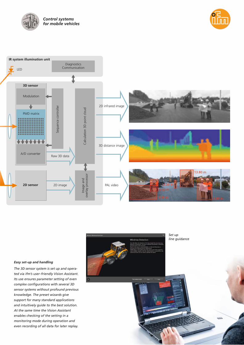
Future-orientedtechnology meetsuser-friendly handling
Augmented reality – 3D smart camera
The function principle of ifm’s PMD
technology is based on time-of-flight
(ToF). The scene is illuminated by modul-
ated, invisible infrared light and the
reflected light hits the PMD sensor. This
sensor is also connected to the source of
modulation. Each pixel of the PMD chip
determines the distances to the scene due
to the phase shift between the transmit-
ted and the received signal.
The integrated, active suppression of
background illumination almost complet-
ely prevents saturation of the image
sensor by extraneous light. That means
that ifm’s PMD 3D sensor can be operated
in bright sunlight up to 120 klx.
Simultaneously the optionally integrated
camera provides a live image with super-
imposed real-time warning messages such
as in dangerous situations or with immin-
ent collisions. The sensor system places
warning symbols, icons, line objects or
texts into the image and combines them
with the video signal. The command to
display these objects can also be given
directly by the machine control system via
CAN bus. The analogue PAL video output
supports conventional monitors and
dialogue modules with video input and
graphics capabilities.
3D sensor system O3M
Set upcollision warning
2D infrared image
3D distance image
PAL video
Modulation
LED
PMD matrix
A/D converter
2D image
Raw 3D data
2D sensor
3D sensor
IR system illumination unitDiagnostics
Communication
Sequ
ence
con
trol
ler
Cal
cula
tion
3D p
oint
clo
udIm
age
and
over
lay
proc
esso
r
3
Control systemsfor mobile vehicles
Easy set-up and handling
The 3D sensor system is set up and opera-
ted via ifm’s user-friendly Vision Assistant.
Its use ensures parameter setting of even
complex configurations with several 3D
sensor systems without profound previous
knowledge. The preset wizards give
support for many standard applications
and intuitively guide to the best solution.
At the same time the Vision Assistant
enables checking of the setting in a
monitoring mode during operation and
even recording of all data for later replay.
Set upline guidance

4
Augmented reality – now in real 3D
The PMD 3D sensor from ifm detects
scenes and objects three-dimensionally
with only one image capture.
This avoids the motion blur that can occur
with line scanners. ifm’s award-winning
patented PMD technology forms the basis
for a sensor system that can cope with the
harsh operating conditions of mobile
machines. Besides the robust and compact
design the 3D sensor system is especially
designed for outdoor applications with
changing light conditions or bright
sunlight. The ifm 3D sensor has no moving
components in contrast to other sensors
such as laser scanners. Therefore it is par-
ticularly robust and not subject to wear.
The so far unique combination of PMD 3D
sensor and 2D camera with integrated
overlay function allows a completely new
perception. Overlay of customer-specific
symbols, warning messages, texts and
even drawings of complex, geometric
shapes is supported by the new 3D smart
camera system. The request for overlay
can either be event-controlled or directly
triggered by the machine control system
via CAN bus.
Areasurveillance
Lineguidance
Distancemonitoring
Objectrecognition
Reflectortracking
Positioninghelp
Collisionwarning
Three-dimensionaldetection of scenesAutomatic detectionof objects
3D sensor system O3M

5
Control systemsfor mobile vehicles
Area surveillancein harsh environments
Constructionmachines 6 - 7
Automation solutionsfor agricultural machinery
Agricultureand forestry 8 - 9
Collision warning andposition determination
Transportand logistics 10 - 13
Automation solutions andarea surveillance in port areas
Transportand logistics 14 - 17
Height and distance monitoringin airport areas
Transportand logistics 18 - 19
3D sensor system O3MHeavy-duty universal camera O2M
Overview of articles /Technical data 20 - 27

3D smart camera:IIntegrated camera with overlayfunction to provide a live imageand real-time warning messages.
Enormous far sightedness:The 3D sensor that is optimisedfor long ranges even detectsmoving reflective objects at adistance of up to 35 metres.
Integrated evaluation:All 3D calculations are made inthe powerful sensor system andthe results are provided via theCAN bus or the Fast Ethernetconnection.
Simply convenient:The parameters of the system areset via the easy-to-handle “ifmvision assistant” for Windows.Ready-to-use function blocks areavailable for the CODESYS soft-ware for machine integration.
6
Collision warning
The integrated, automatic object recog-
nition detects up to 20 stationary or
moving objects in the path of a construc-
tion vehicle. By comparing the current
speed, the motion vector and fixed param-
eters such as the braking distance, the
collision probability is calculated by the
3D sensor and transferred to the machine
control system via CAN bus or Ethernet
and then signalled to the driver.
Area surveillancein harsh environments
Construction machines

7
Distance monitoring
For simple distance functions the integrat-
ed distance monitoring provides up to
64 adjustable regions of interest (ROIs),
i.e. individual regions whose distances are
to be monitored. Rear area monitoring
can be implemented or automation or
assistance tasks can be solved.
XXCollision avoidance
Collision Status:
Predicted impact velocity of collision:
Predicted time to collision:
ID of the object causing the collision:
Crash predicted
2.70 m/s
1.28 s
69
XXXXObject information
ID:
Type:
x1:
delta-x:
y1:
delta-y:
Velocity x-direction:
Velocity y-direction:
69
Normal
7.52 m
- 0.08 m
- 0.22 m
1.32 m
- 3.00 m/s
0.00 m/s
Construction vehicle
Learn more at www.ifm.com/gb/o3m-ca

For the harshest environ-ments:Since the sensor does not haveany moving components, it isvirtually free of wear. Its highambient temperature rangeof -40 to 85 °C is the basis foruniversal use.
Resistant to extraneouslight:The PMD technology ensures highrepeatability of the measured dataeven in difficult ambient lightconditions or with direct sunlight.
Communicative:Interfaces such as CAN withJ1939 or CANopen and FastEthernet are integrated as stan-dard. Self-diagnostic functionsfrom the sensor to the IR systemillumination unit continuallymonitor the system status.
Reliable and fast:With a highly developed algo-rithm from the automotive sectorand a frame rate of up to50 frames / second the sensorallows fast and reliable calcula-tion of the 3D information.
8
Automation solutionsfor agricultural machinery
Agriculture and forestry
9
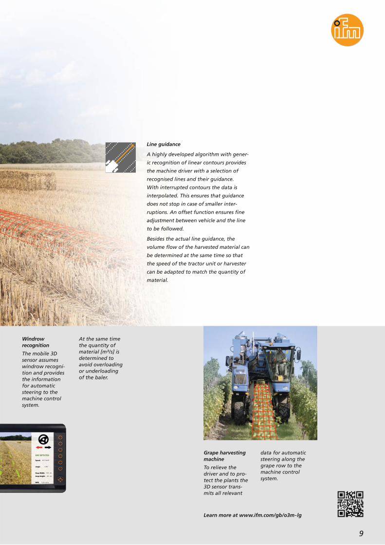
Windrowrecognition
The mobile 3Dsensor assumeswindrow recogni-tion and providesthe informationfor automaticsteering to themachine controlsystem.
At the same timethe quantity ofmaterial [m³/s] isdetermined toavoid overloadingor underloadingof the baler.
Grape harvestingmachine
To relieve thedriver and to pro-tect the plants the3D sensor trans-mits all relevant
data for automaticsteering along thegrape row to themachine controlsystem.
Line guidance
A highly developed algorithm with gener-
ic recognition of linear contours provides
the machine driver with a selection of
recognised lines and their guidance.
With interrupted contours the data is
interpolated. This ensures that guidance
does not stop in case of smaller inter-
ruptions. An offset function ensures fine
adjustment between vehicle and the line
to be followed.
Besides the actual line guidance, the
volume flow of the harvested material can
be determined at the same time so that
the speed of the tractor unit or harvester
can be adapted to match the quantity of
material.
Learn more at www.ifm.com/gb/o3m-lg

Integrated camera:An additional camera in the3D sensor system provides themachine operator with a user-friendly overview.
Continuously reliable:Thanks to the specially modulat-ed infrared light a continuouslyhigh recognition rate can beachieved even with reflectivematerial of different intensity.All that with a minimum responsetime of only 40 ms.
High coverage:The range of up to 15 m intypical environments and upto 35 m on reflective objectsensures universal use.
Goal-oriented:Object distances and dimensionsare automatically provided in aclear grid using the selectableworld coordinate system.The ground recognition integrat-ed in the algorithm ensures highunambiguity of object recogni-tion.
10
Area surveillanceon machines and vehicles
Transport and logistics

Area surveillance
With more than 1,000 individual distance
values the 3D sensor recognises objects in
the detection range and signals this to the
machine control system depending on the
distance to the machine.
11
Waste disposalvehicle
Automatic recog-nition of danger-ous situations suchas during revers-ing or placing ofcontainers.
The integratedlogic functionsallow to solve ap-plications withoutadditional complexprogramming.
Learn more at www.ifm.com/gb/o3m-as

12
Collision warning andposition determination
Transport and logistics
Continuously reliable:Thanks to the specially modulat-ed infrared light a continuouslyhigh recognition rate can beachieved even with reflectivematerial of different intensity.All that with a minimum responsetime of only 40 ms.
High coverage:The range of up to 15 m intypical environments and upto 35 m on reflective objectsensures universal use.
Goal-oriented:Object distances and dimensionsare automatically provided in aclear grid using the selectableworld coordinate system.The ground recognition integrat-ed in the algorithm ensures highunambiguity of object recogni-tion.
Truck positioningon a loading bay
To protect thelogistic facilitiesthe driver is in-formed as soon ashe has reachedthe ideal dischargeposition at the bay.
Driver assistanceduring reversing
To preventaccidents thehazardous areabehind the forklift is detected in3D and the driveris informed in timeby a warningmessage before apossible collision.Simultaneouslythe machine con-trol system can geta command tolower the speed,for example.

Learn more at www.ifm.com/gb/o3m-dm
13
Position determination of
transport vehicles
For simple position determination the
integrated distance monitoring provides
up to 64 adjustable regions of interest
(ROIs), i.e. individual regions whose
distances are to be monitored.
This ensures, for example, position deter-
mination of a transport vehicle under-
neath a loading point.
0 m
5 m
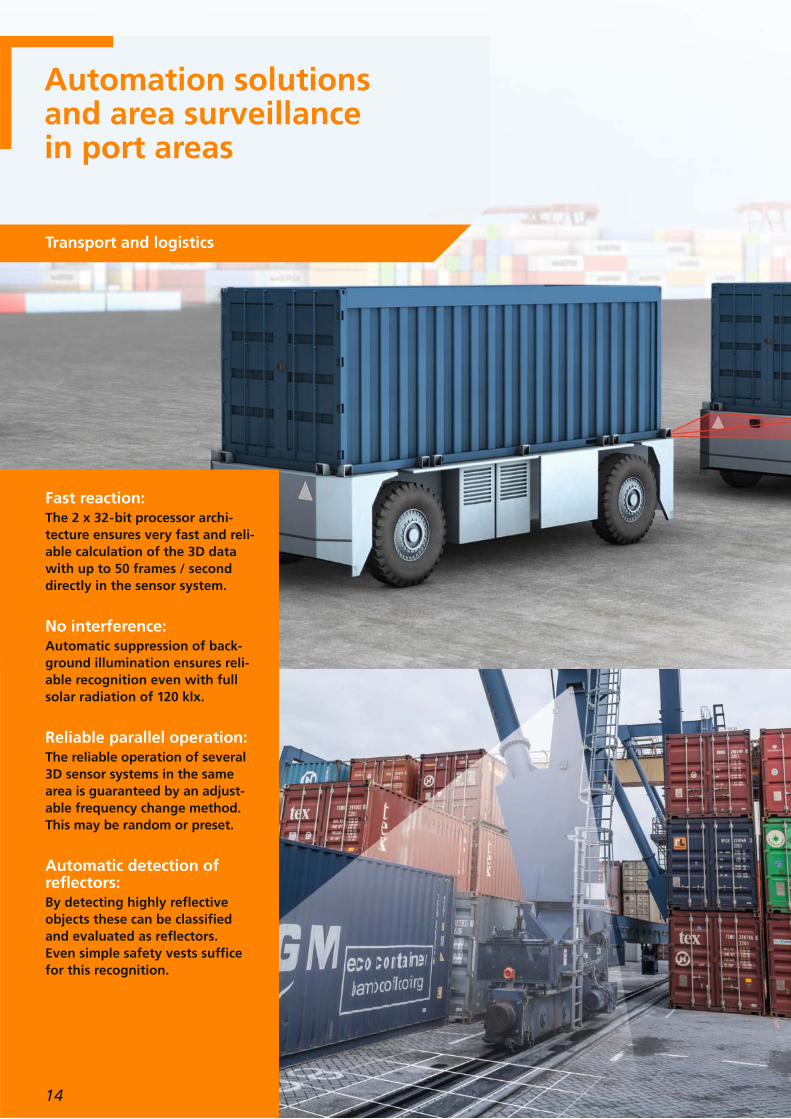
Fast reaction:The 2 x 32-bit processor archi-tecture ensures very fast and reli-able calculation of the 3D datawith up to 50 frames / seconddirectly in the sensor system.
No interference:Automatic suppression of back-ground illumination ensures reli-able recognition even with fullsolar radiation of 120 klx.
Reliable parallel operation:The reliable operation of several3D sensor systems in the samearea is guaranteed by an adjust-able frequency change method.This may be random or preset.
Automatic detection ofreflectors:By detecting highly reflectiveobjects these can be classifiedand evaluated as reflectors.Even simple safety vests sufficefor this recognition.
Automation solutionsand area surveillancein port areas
Transport and logistics
14

Learn more at www.ifm.com/gb/o3m-sd
15
Automatic vehicle tracking with
collision warning
A special classification of reflective objects
is used as basis for automatic tracking of
the vehicle ahead. The proven and highly-
developed algorithm from the automotive
sector is relied on.
For example, the minimum and maximum
distance to the vehicle ahead is set or
recognition is limited to a certain arrange-
ment of reflectors via various parameters.
An additional collision warning ensures
that obstacles are reliably detected and
signalled to the machine control system in
two stages. Interference by direct solar
radiation or other 3D sensor systems is
automatically suppressed.
Easy area monitoring in ports
The integrated functions in the 3D sensor
are especially suited for monitoring the
rails of a gantry crane. The sensor detects
an obstacle on the rails or extending into
the path and signals this to the crane
driver in time. The crane is stopped auto-
matically in critical situations.

Integrated camera:An additional camera in the3D sensor system ensures a user-friendly overview for themachine operator. Recognisedobstacles are superimposed onthe camera image.
Customer-specificwarning messages:The overlay function of the 3Dsmart camera also allows overlayof graphics and texts by themachine control system viaCAN bus.
No interference:Automatic suppression of back-ground illumination ensures reli-able recognition even with fullsolar radiation of 120 klx.
Reliable parallel operation:The reliable operation of several3D sensor systems in the samearea is guaranteed by an adjust-able frequency change method.This may be random or preset.
16
Automation solutionsand area surveillancein port areas
Transport and logistics

Learn more at www.ifm.com/gb/o3m-ca
17
Collision warning
The integrated, automatic object recogni-
tion detects up to 20 stationary or moving
objects in the path of a reach stacker.
On the basis of the current speed, the
moving vector and fixed parameters, for
example the braking distance, the
collision probability is calculated by the
3D sensor. It is transferred to the machine
control system via CAN bus or Ethernet
and signalled to the driver. In a live image
provided by the integrated camera the
recognised obstacles are highlighted.

High-performancemeasuring system:Thanks to the patented PMDtechnology it is possible to havea high repeatability of themeasured data even on materialsof different reflectivity. The multi-phase measuring system evendetects interference caused bydust or water mist formation.
Robust sensors:The protection ratings IP 67 andIP 69K and a wide temperaturerange of -40 to 85 °C ensureuniversal use in different appli-cations.
High reliability:Integrated self-diagnostic func-tions from the sensor to the IRsystem illumination unit alwaysensure comprehensive infor-mation of the machine controlsystem about the current functionstatus of the 3D sensor. In case ofdamage, interference or heavysoiling the sensor system can givecorresponding signals in time.
Height monitoringfor tankers
The integrateddistance function‘minimum dis-tance’ can monitorup to 64 selectablepoints above thetanker simulta-neously.
The driver can,for example, besupported whenhe positions thetanker underneaththe aeroplanewing or is in-formed if the wingis lowered.
18
Height anddistance monitoringin airport areas
Transport and logistics

Simple distance monitoring
The integrated function ‘minimum
distance’ can also be used for simple area
monitoring. It informs the driver when a
minimum distance has been reached and
simultaneously it signals where this next
distance is in the recognition field.
Assistance foraircraft tractors
Thanks to easymonitoring of apre-defined areathe 3D sensor caneither provide an
Positioning anddocking help forairport groundequipment
More than 1,000individual measure-ments preciselydetect the environ-ment of the con-veyor belt.Customer-specificapplication solu-tions can be
implemented fastand easily usingaltogether 64‘regions of inter-est’ (ROIs), i.e.individual regionswhose distancesare to be moni-tored.
end positionmessage or even acontour imageof the nose wheelto the machinecontrol system.
19
Learn more at www.ifm.com/gb/o3m-sd

Suitableillumination
20
Order no.Order no.Horizontal x verticalangle of aperture
[°]
Type
Technical dataand accessories
3D sensor system O3M
Mobile 3D sensor without data preprocessing1) 70 x 23 IR system illumination unit
PMD 3D sensor O3M
O3M950O3M150
Mobile 3D sensor with integrated 2D camera1) 70 x 23 (3D)90 (2D) IR system illumination unit O3M950O3M250
Mobile 3D sensor without data preprocessing1) 95 x 32 IR system illumination unit O3M960O3M160
Mobile 3D sensor with integrated 2D camera1) 95 x 32 (3D)120 (2D) IR system illumination unit O3M960O3M2603)
Mobile 3D smart sensor2) 70 x 23 IR system illumination unit O3M950O3M151
Mobile 3D smart sensorwith integrated 2D/3D overlay
70 x 23 (3D)90 (2D) IR system illumination unit O3M950O3M251
Mobile 3D smart sensor2) 95 x 32 IR system illumination unit O3M960O3M161
Mobile 3D smart sensorwith integrated 2D/3D overlay
95 x 32 (3D)120 (2D) IR system illumination unit O3M960O3M2613)
1) Synchronous output of the 2D IR image and the 3D distance image as input information for customer-specific image processing2) Incl. application wizards, see table page 223) Types O3M260 / O3M261 available as of 2nd quarter of 2017
Technical data
Type of sensor
Pixel resolution [Pixel]
Illumination
PMD 3D chip
64 x 16
Further technical datadevices with 2D camera
Sensor type
PAL resolution [Pixel]
1/4" 4:3 VGA CMOS image sensor colour
640 x 480
IR system illumination 850 nm (wave length)
max. frame rate [Hz] 25 / 33 / 50
Connection M12 connector
Protection rating / protection class IP 67 / IP 69K, III
Operating voltage [V DC] 9...32
Ambient temperature [°C] -40...85
Note:The 3D sensors of the O3M series can be used for example as driver assistance for collision warning or for area monitoring. They are photoelectricsystems whose function may be impaired by heavy soiling, for example. This system does not meet the requirements of IEC 61496 for electro-sensitive protective equipment and must not be used for implementing a safety function for operator protection. The 3D sensors of the O3M seriescan be used to assist the machine operator. The machine operator is, however, always fully responsible.

21
Wiring for parameter setting
Wiring for installation
Learn more at www.ifm.com/gb/o3m
SensorO3M151
O3M2514)
IR systemillumination unit
O3M950
Connection cable MCIE3M12x
Optional connection cableE3M160
Adapter cableEC2114
Ethernet connectionE11898
Voltage supply 12/24 V DC
Voltage supply 12/24 V DCE3M13x
Connection cableUSB
CANfoxEC2112
Videograbber4)
PC
Power supply
4) Type O3M251 provides an additional analogue video output
Connection cable CANE1159x
Voltage supply12/24 V DC
E3M13x
Optional video connection cableE3M1514)
Voltage supply 12/24 V DC
Connection cable CANE1159x
Voltage supply12/24 V DC
EVC07x
SensorO3M151
O3M2514)
IR systemillumination unit
O3M950
Connection cable MCIE3M12x

22
Type Description Order no.
CAN/RS232 USB Interface CANfox EC2112
Adapter cable set for CANfox EC2114
Operating software for vision sensors E3D300
Weather protective cover,stainless steel black E3M101
U-shaped bracket,suitable for sensor or illumination unit,stainless steel black
E3M102
Type Description Order no.
U-shaped bracket,suitable for sensor or illumination unit,stainless steel
E3M100
Mounting set for clamp mounting,Ø 14 mm, stainless steel / high-gradestainless steel
E3M103
Reflector triangular,200 mm E3M140
Reflective tape triangular,self-adhesive, 200 mm E3M141
Reflective tape 210 x 297 mm,self-adhesive E3M142
Accessories
Technical dataand accessories
3D sensor system O3M
Application wizardsavailable in the ifm Vision Assistant
Application examples
Monitoring the area behind the construction vehicles and fork lifts,monitoring the blind spots, recognition of collisions when moving forwards,
collision recognition with dockside cranes.
Application wizards Types O3M151 / O3M161
Collision warning as driver assistance
Area surveillance on drilling rigs,waste disposal vehicles and cranes.Area surveillance for mobile or stationary machinery
Automatic tracking of transport vehicles aheadand keeping safety distances.Automatic following for driverless transport vehicle
Automatic windrow recognition and calculation of the volume flow,automatic steering of a grape harvester.Line guidance

23
Type Description Order no.
MCI connection cable, connectionsensor / system illumination unit, 1 m E3M121
MCI connection cable, connectionsensor / system illumination unit, 2 m E3M122
MCI connection cable, connectionsensor / system illumination unit, 3 m E3M123
M12 socket, voltage supplysystem illumination unit, 2 m,PUR cable, 4 poles
E3M131
M12 socket, voltage supplysystem illumination unit, 5 m,PUR cable, 4 poles
E3M132
M12 socket, voltage supplysystem illumination unit, 10 m,PUR cable, 4 poles
E3M133
M12 video connection cable,connection sensor / display PDM360,5 m
E3M151
M12 video connection cable,connection sensor / display PDM360,11 m
E3M152
M12 video connection cable,connection sensor / display PDM360,16 m
E3M153
M12 video connection cable,connection sensor / display PDM360,21 m
E3M154
Type Description Order no.
M12 socket, CAN bus,2 m, PUR cable, 5 poles E11596
M12 socket, CAN bus,5 m, PUR cable, 5 poles E11597
Ethernet, cross-over patch cable,2 m, PVC cable, M12 / RJ45 E11898
E12226
Ethernet, cross-over patch cable,10 m, PVC cable, M12 / RJ45 E12204
Ethernet, cross-over patch cable,20 m, PVC cable, M12 / RJ45 E12205
Ethernet, cross-over patch cable,2 m, PVC cable, M12 / RJ45,angled / straight
E3M159M12 video extension cable, 5 m
E3M160M12 video adapter cable / Cinch plugfor connection of a video grabber, 1 m
E3M161Video adapter cable M12 socket to M16 connector,for connection to MultiViewBox, 1 m
Connection technology
E3M120TPU connection cable, connectionsensor / system illumination unit, 0,25 m

24
Technical dataand accessories
Heavy-duty universal camera O2M
Type
CMOS camera
Angle of aperture
[°]
78
Order no.Mirror function
– O2M200
CMOS camera 78 integrated O2M201
CMOS camera 115 – O2M202
CMOS camera 115 integrated O2M203
Technical data
Type of sensor
PAL resolution [Pixel]
Image repetition rate [fps]
1/4" 4:3 VGA CMOS image sensor colour
680 x 480
25
Connection Connection cable 0.5 m withM16 connector
Protection rating / protection class IP 68 / IP 69K
Operating voltage [V DC] 8...32
Lens heating automatical
Ambient temperature [°C] -40...85
Camera with analogue video output O2M
Type Description Order no.
Protective metal cover, stainless steel E2M212
Dome fixture E2M211
Vibration damper set E2M213
Replacement fixture E2M210
Accessories
Description Order no.
Video splitter, visualises up to 4 cameraimages (PAL) on a conventional monitoror a process and dialogue module
E2M250
M16 connection cable, 3.85 m, 8 poles,for the voltage supply of theE2M250 MultiViewBox, open cable end
E2M251
M16 socket, wirable, 8 poles,for the voltage supply of theE2M250 MultiViewBox
E2M252
MultiViewBox
Type
Technical data
Video signal PAL, 720 H x 576 V (active 680 x 480)
Inputs 4
Connection M16 connectors

25
Type Description Order no.
Adapter cable, M12 connector toM16 socket, black, PVC cable.To connect a camera to the PDM NG
E2M200
Adapter cable, M12 connector toM16 socket, black, PVC cable.For connection of two cameras to thePDM NG
E2M201
Connection cable, M16 connector toM16 socket, 5 m black, PVC cable E2M203
Connection cable, M16 connector toM16 socket, 11 m black, PVC cable E2M204
Connection cable, M16 connector toM16 socket, 16 m black, PVC cable E2M205
Connection cable, M16 connector toM16 socket, 21 m black, PVC cable E2M206
Connection technology
Type Description Order no.
7" colour display, 9 function keys,navigation key, 2 x analogue video input,touch screen
CR1082
7" colour display, 9 function keys,navigation key, 2 x analogue video input CR1085
7" colour display, 8 function keys,2 x analogue video input CR1083
7" colour display, 9 function keys,encoder, 2 x analogue video input CR1084
12" colour display, 13 function keys,navigation key, 2 x analogue video input CR1200
12" colour display, 13 function keys,navigation key, 2 x analogue video input,touch screen
CR1201
Dialogue module PDM360 NG
Learn more at www.ifm.com/gb/o2m
Adapter cableE2M200
3D cameraO3M251
3D cameraO3M251
Adapter cableE3M161
MultiViewBoxE2M250
Connection cableE2M203
CameraO2M2xx
CameraO2M2xx

26
OverviewOperating distance /field of view size
3D sensor system O3M
Type O3M150 / O3M151 / O3M250 / O3M251 angle of aperture 70° x 23°
7 x 214 x 4
21 x 6
42 x 12
Operating distance [m] 30
field of view size [m]
3D sensor
15105
ODobject recognition vehicle
sunny (~120 kLux) 0.25...30 – –
cloudy (~20 kLux) 0.25...40 – –
darkness 0.25...50 – –
ODobject recognition
highly reflectiveobject (e.g. high
visibility vest)
sunny (~120 kLux) 1...40 – –
cloudy (~20 kLux) 1...60 – –
darkness 1...80 – –
ODobject recognition person5)
sunny (~120 kLux) 0.25...12 – –
cloudy (~20 kLux) 0.25...16 – –
darkness 0.25...20 – –
DI / BFdistance imagebasic functions
sunny (~120 kLux) – 0.25...12 ± 15
cloudy (~20 kLux) – 0.25...15 ± 10
darkness – 0.25...30 ± 5
Type O3M151 / O3M251 measurement accuracy
5) The term person is only to be understood as a reference for size
Note:The 3D sensors of the O3M series can be used for example as driver assistance for collision warning or for area monitoring. They are photoelectricsystems whose function may be impaired by heavy soiling, for example. This system does not meet the requirements of IEC 61496 for electro-sensitive protective equipment and must not be used for implementing a safety function for operator protection. The 3D sensors of the O3M seriescan be used to assist the machine operator. The machine operator is, however, always fully responsible.
Softwareversion
Object type Operatingconditions
Measuring rangefor object recognition
[m]
Typ. measuring rangefor ROI
[m]
Typ. measurementaccuracy
[cm]

27
20.8 x 5.511 x 2.8
32.8 x 8.3
65 x 17
Type O3M160 / O3M161 / O3M2603) / O3M2613) angle of aperture 95° x 32°
5 10 1530
field of view size [m]
3D sensor
Operating distance [m]
ODobject recognition vehicle
sunny (~120 kLux) 0.25...21 – –
cloudy (~20 kLux) 0.25...30 – –
darkness 0.25...35 – –
ODobject recognition
highly reflectiveobject (e.g. high
visibility vest)
sunny (~120 kLux) 1...29 – –
cloudy (~20 kLux) 1...42 – –
darkness 1...55 – –
ODobject recognition person5)
sunny (~120 kLux) 0.25...9 – –
cloudy (~20 kLux) 0.25...12 – –
darkness 0.25...15 – –
DI / BFdistance imagebasic functions
sunny (~120 kLux) – 0.25...8 ± 15
cloudy (~20 kLux) – 0.25...11 ± 10
darkness – 0.25...21 ± 5
Type O3M161 / O3M2613) measurement accuracy
3) Types O3M260 / O3M261 available as of 2nd quarter of 2017 5) The term person is only to be understood as a reference for size
Softwareversion
Object type Operatingconditions
Measuring rangefor object recognition
[m]
Typ. measuring rangefor ROI
[m]
Typ. measurementaccuracy
[cm]

ifm a
rtic
le n
o. 7
8002
159
· We
rese
rve
the
right
to
mak
e te
chni
cal a
ltera
tions
with
out
prio
r no
tice.
· Pr
inte
d in
Ger
man
y on
non
-chl
orin
e bl
each
ed p
aper
. 10
/16
Visit our website:www.ifm.com
Position sensors
Sensors formotion control
Industrial imaging
Safety technology
Process sensors
Systems formobile machines
Industrialcommunication
Condition monitoringsystems
Connectiontechnology
Software
Power supplies
AccessoriesIO-Link
years
W
ARRANTY
on ifm products
Identification systems
ifm electronic gmbh
Friedrichstraße 145128 EssenTel. +49 / 201 / 24 22-0Fax +49 / 201 / 24 22-1200E-mail [email protected]