canalis_design guide & tech characteristics.pdf
DESCRIPTION
Design Guide canalisTRANSCRIPT

3
De
sig
n
gu
ide
Schneider Electric
Contents Design guides andCharacteristics
Design guide
Simplified design guide for lighting distributionLighting-technology review 30Installation 34Selection of Canalis busbar trunking 35Determining the operational current 36Overload protection 37Short-circuit protection 39Check on voltage drop 40
Simplified design guide for power distributionPower distribution via Canalis 42
Simplified design guideDetermining the degree of protection 44
Characteristics
Canalis KDP, 20 A 46
Canalis KBA, 25 and 40 A 47
KBL Industrial luminaires 48
Canalis KBX, Strip lighting distribution 25 A 50
Canalis KBB, 25 and 40 A 52
KBC tap-off units, KDP connections 53
Canalis KN, 40 to 160 A 54
Canalis KS, 100 to 1000 A 56
Design and quotation tools
CanFast 58

K00E21000.fm/2 Schneider Electric
Design guide Simplified design guide for lighting distributionLighting-technology review
Selection of lighting levelsThe table below indicates the necessary illumination in lux for different tasks.
In general, a higher level of illumination is required when:
b work involves small parts,�objects are dark,�the task requires a high level of visual attention,�work is carried out at high speeds.
Selection of light sourcesVisual comfort depends on the level of illumination (in lux) and the colour
temperature (in degrees Kelvin).
The Kruithof diagram below can be used to make an optimum choice.
The blue zone represents a comfortable environment.
The table below sums up the essential characteristics of the main types of light
source.
DD
21
04
96
DD
21
04
97
Type of light source Colour temperature(°K)
Length of tubes(m)
Power(W)
Luminous flux (Lm)
Incandescent lamps
2800 to 3000 - 75 850
- 150 2100
- 300 4750
- 750 13500
White industrial fluorescent tube
With starter 4250 to 4500 1.20 40 3200
1.50 65 5100
1.50 80 5900
Instant start 4250 to 4500 1.20 40 2900
1.50 65 4800
2.40 105 8000
Mercury vapour With starter 3300 to 4300 - 125 6500
- 250 14000
- 400 24000
- 700 42000
- 1000 60000

De
sig
n
gu
ide
K00E21000.fm/3Schneider Electric
Design guide Simplified design guide for lighting distributionLighting-technology review
Selection of the lighting systemDirect lighting is used in offices, workshops and factories.
Semi-direct and indirect lighting is generally reserved for exhibitions, auditoriums,
etc.
On industrial premises, direct lighting is generally used, from the most intensive to
the most extensive, i.e. from class A to class J according to standards UTE 71-120
and 121.
Tables A and B determine the photometric class of luminaires depending on the
rating of the sources and the illuminance.
Table A - Lighting in offices
Table B - Lighting in workshops and factories
Distribution of light sourcesThe maximum distance between two luminaires is indicated in the table below, taking
into account the photometric class and the height h.
Distribution is determined by the position of work stations (caution concerning
reflection), which in turn determines the number of luminaires, on the condition that
the total luminous flux is sufficient (see next page).
Intensive Extensive
DD
38
23
96
Class A to Class J
Illuminance in lux Fluorescent tubes
40 W1.20 m
65 W1.50 m
105 W2.40 m
0 to 600 E E -
800 D D -
1000 D D C
1200 C C C
1500 C C C
Illuminance in lux Fluorescent tubes
40 W1.20 m
65 W1.50 m
80 W1.50 m
105 W2.40 m
Other lamps
0 to 200 G G - - E
400 F F - - D
600 E E - - C
800 D D - - C
1000 D D C C B
1200 C C C C B
1500 C C C C A
DD
21
04
98
DD
38
23
98
Incorrect Correct
Luminaire class Maximum distance between two luminaires
A e = 0.90 x h
B e = 1.00 x h
C e = 1.10 x h
D e = 1.20 x h
E e = 1.30 x h
F e = 1.40 x h
G e = 1.45 x h
H e = 1.50 x h
I e = 1.50 x h
J e = 1.50 x h

K00E21000.fm/4 Schneider Electric
Design guide Simplified design guide for lighting distributionLighting-technology review
Total luminous fluxThe total luminous flux required for the desired illuminance in a room is provided by
the equation below:
F: Total luminous flux required (in lumens).(Lumen: quantity of light per second reaching the working plane).
E: Illuminance (in lux).(1 lux = 1 lumen/m2).
S: Surface area of room (in m2).
d: Depreciation factor taking into account ageing of light sources and of the room (1.3
to 1.5).
u: The walls and ceiling absorb a part of the flux emitted by the light sources. The
utilisation factor is the ratio between the luminous flux reaching the working plane
and that emitted by the lamps.�It depends on:
�room proportions according to the K index:
�reflectance factors of the walls and ceiling,
�flux distribution of the luminaires.
Determining the utilisation factor "u"
DD
21
04
99
FE S! d!
u----------------------=
Ka b!
h a b+" #--------------------=
Type of lighting Room index Reflectance factor
Ceiling 70 % Ceiling 50 %
K Walls 70 % 50 % 10 % Walls 70 % 50 % 10 %
Direct lighting 0.6 0.49 0.42 0.39 0.46 0.42 0.39
Polished-aluminium industrial reflector for mercury-vapour lamps
0.8 0.58 0.51 0.48 0.54 0.51 0.48
1 0.64 0.56 0.53 0.59 0.55 0.53
1.25 0.69 0.60 0.58 0.62 0.60 0.57
1.5 0.73 0.64 0.61 0.65 0.63 0.61
2 0.78 0.68 0.66 0.69 0.37 0.65
2.5 0.81 0.71 0.69 0.72 0.70 0.69
3 0.84 0.73 0.72 0.73 0.72 0.71
4 0.87 0.75 0.74 0.75 0.74 0.73
5 0.88 0.76 0.75 0.76 0.75 0.74
Direct lighting 0.6 0.31 0.24 0.20 0.28 0.23 0.20
Lacquered sheet-metal industrial reflector for two fluorescent tubes
0.8 0.39 0.31 0.28 0.36 0.31 0.27
1 0.45 0.37 0.33 0.41 0.36 0.33
1.25 0.51 0.42 0.38 0.46 0.41 0.38
1.5 0.56 0.46 0.43 0.50 0.45 0.42
2 0.62 0.52 0.49 0.55 0.51 0.48
2.5 0.67 0.56 0.53 0.58 0.55 0.53
3 0.70 0.59 0.56 0.61 0.58 0.56
4 0.74 0.63 0.61 0.64 0.62 0.60
5 0.76 0.65 0.63 0.65 0.64 0.62

De
sig
n
gu
ide
K00E21000.fm/5Schneider Electric
Design guide Simplified design guide for lighting distributionLighting-technology review
Example of a design projectPreliminary design of lighting for a factory:�
length: 65 m,�width: 25 m,�height: 6 m.
Selection of light sources taking into account the long daily use and the luminaire
installation height set at 5 metres.
Luminaires in photometric class E are selected (table B, page 3).
Distribution of luminairesDistance between two class E luminaires: e = 1.30 x h = 1.30 x 5 = 6.5 m.
Number of luminaires over the length: 65 / 6.5 = 10 luminaires.
Number of luminaires over the width: 25 / 6.5 = 3.8 (i.e. 4 rows of 10 luminaires).
Total luminous flux:
E: Illuminance: 250 lux.
S: Surface area: 65 x 25 = 1 625 m2.
d: Depreciation factor: 1.5.
u: Utilisation factor: the table on page 4 gives "u" directly as a function of K.
that we round to 4
Given a reflectance factor of 50 % for the ceiling and 10 % for the walls and the use
mercury-vapour lamps:
u = 0.73.
Total luminous flux:
Rating of each source (f):
In the table on page 2, us allows to choose 400 W (24 000 lumens) mercury-vapour
lamps which provide a lighting level of slightly above 250 lux.
Note : If changes in workshop layout require modifications in the illumination on the working plane, Canalis makes it easy to add or remove luminaires.
DD
38
24
00
DD
21
05
00
DD
21
05
45
FE S! d!
u----------------------=
Ka b!
h a b+" #--------------------
25 65!
5 25 65+" #-------------------------- 3 6,= = =
FE S! d!
u----------------------
250 1625 1 5,!!
0 73$----------------------------------------- 834760= = = lumens
fF
Number---------------------
834760
40------------------ 20869= = = lumens
of luminaires

K00E21000.fm/6 Schneider Electric
Design guide Simplified design guide for lighting distributionInstallation
Due to its flexible design, KDP busbar
trunking simplifies routing and thus reduces
design and installation times.
It is the optimum solution for installations
with false ceilings or floors.
KBA and KBB busbar trunking is ideal
where the building structure cannot support
the luminaires.
They offer an IP55 degree of protection
which means they can be installed in all
types of buildings.
The competitiveness and aesthetics of KBX
busbar trunking, with built-in luminaires, are
unmatched.
It is the optimum solution for intensely
lighted stores and buildings.
Busbar-trunking selection
DD
21
02
05
Fixing distanceKBA and KBB busbar trunking
DD
21
02
06
The fixing distance for KBA and KBB busbar trunking depends on the number and
weight of the luminaires, as well as the building structure. The table below indicates
the maximum permissible load (kg) between two fixing points for a deflection of
1/500. If the load is concentrated between two fixing points (mercury-vapour lamps),
apply a coefficient of 0.6 to the values.
The busbar trunking:
cannot support the luminaires
must carry a number of
circuits
must support the luminaires
The fixing distance between centres is:
>3 m � 3 m
� IP20>IP20
Aesthetics not required
Aesthetics required
The required degree of protection is:
KDP KBB KBAKBA or
KBXKBX
Maximum load(kg)
Type of busbar trunking
tap-offs distance (m)
Fixing distance a (m)
2 2.5 3 3.5 4 4.5 5 5.5 6
KBA 1 34 22 15 no load
0.5 29 19 13 no load
KBB 1 circuit 60 60 48 35 27 21 17 no load
2 circuits 60 51 41 30 23 18 15 no load

De
sig
n
gu
ide
K00E21000.fm/7Schneider Electric
Design guide Simplified design guide for lighting distributionSelection of Canalis busbar trunking
The tables below indicate the possible fixing distances in metres for a deflection
of 1/350, depending on the type of luminaire used and the installation method
(trunking installed edgewise). .
Industrial reflector type fluorescent luminaires without protection grill
Industrial reflector type fluorescent luminaires with protection grill
Dust and damp-proof industrial reflector type fluorescent luminairesClose together Far apart Across fixing point
DD
20
50
12
Power Unit weight Possible spacing
(W) (kg) (metre)
Without With Dust and
protection gril protection gril damp-proof
KBA KBB KBA KBB KBA KBB
1 x 36 4.20 5.20 3.30 3.00 5.00 3.00 5.00 4.00 6.00
1 x 58 5.30 6.50 4.20 3.00 5.00 3.00 5.00 4.00 6.00
2 x 36 4.90 5.90 5.20 3.00 5.00 3.00 5.00 4.00 6.00
2 x 58 6.30 7.50 5.39 3.00 5.00 3.00 5.00 4.00 6.00
Mercury-vapour luminairesBetween two fixing points Next to a fixing point
DD
20
50
13
Power Unit weight Possible spacing
(W) (kg) (metre)
KBA KBB KBA KBB
250 6.00 3.00 5.00 4.00 6.00
8.50 3.00 5.00 4.00 6.00
10.00 3.00 5.00 4.00 6.00
400 6.50 3.00 5.00 4.00 6.00
9.00 3.00 5.00 4.00 6.00
11.00 3.00 5.00 4.00 6.00

K00E21000.fm/8 Schneider Electric
Design guide Simplified design guide for lighting distributionDetermining the operational current
The tables below show the operational current as a function of the type and number
of luminaires installed on a single-phase line (L + N) supplied with 230 V AC current.
For a three-phase + N (AC, 400 V between phases) line, with equivalent phase
current, the number of luminaires is three times higher.
Procedure�identify the type of luminaire (e.g. 2 x 58 W compensated fluorescent),�on the corresponding line, select the number (or next highest) of installed
luminaires (e.g. 26 if there are 23 luminaires),�at the bottom of the table, read the corresponding operational current (e.g. 20 A).
�Then refer to:
�page 10 to determine the type of busbar trunking and cables sizes as a function of
type of protection (circuit breaker or fuse),�
page 13 to check voltage drop in the busbar trunking and the supply cable.
(1) For this type of luminaire, for 25 A and higher, select a 40 A KBA or KBB to take into account the overcurrent during starting.
DD
20
50
14
Ph + N distribution
DD
20
50
15
3Ph + N balanced distribution
Industrial reflector type fluorescent luminairesType of ballast Power
(W)Number of luminaires on the line
Single-phase line Three-phase + N line
Compensated 1 x 36 33 53 66 - - - 99 - - - - -
1 x 58 25 40 50 62 - - 75 - - - - -
2 x 36 21 33 42 52 67 - 63 99 - - - -
2 x 58 13 20 26 32 41 52 39 60 78 96 - -
Non-compensated 1 x 36 22 35 44 55 - - 66 105 - - - -
1 x 58 14 22 28 35 45 - 42 66 84 - - -
2 x 36 11 17 22 27 35 44 33 51 66 81 - -
2 x 58 7 11 14 17 22 28 21 33 42 51 66 84
Operational current (A) 10 16 20 25 32 40 10 16 20 25 32 40
Mercury-vapour luminairesType of ballast Power
(W)Number of luminaires on the line
Single-phase line Three-phase + N line
Compensated 250 7 11 14 17 22 21 33 42 51 66
400 4 6 8 10 13 12 18 24 30 39
Non-compensated 250 4 7 9 11 14 12 21 27 33 42
400 3 4 6 7 9 9 12 18 21 27
Operational current (A) 10 16 20 25(1) 32 16 20 25(1) 32
Type of busbar trunking 20 A KDP25 A KBA or KBB
40 A KBA or KBB
25 A KBA or KBB
40 A KBA or KBB
High-pressure sodium-vapour luminairesType of ballast Power
(W)Number of luminaires on the line
Single-phase line Three-phase + N line
Compensated 150 11 17 22 27 35 33 51 66 81 105
250 7 11 14 17 22 21 33 42 51 66
400 4 7 9 11 14 12 21 27 33 42
Non-compensated 150 5 8 11 13 17 15 24 33 39 51
250 3 5 6 8 10 9 15 18 24 30
400 2 3 4 5 6 3 9 12 15 18
Operational current (A) 10 16 20 25(1) 32 10 16 20 25(1) 32
Type of busbar trunking 20 A KDP25 A KBA or KBB
40 A KBA or KBB
25 A KBA or KBB
40 A KBA or KBB

De
sig
n
gu
ide
K00E21000.fm/9Schneider Electric
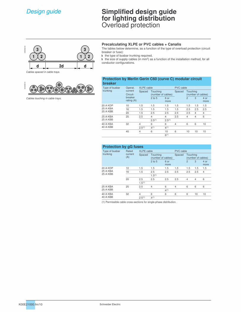
Design guide Simplified design guide for lighting distributionOverload protection
Precalculating XLPE or PVC cables + CanalisDrawn from the Ecodial low-voltage installation-calculation software, the information
provided here assists in defining busbar trunking (cables and Canalis) and their
protection in compliance with installation standards and calculation guide.
Protection of the main busbar trunking (cable + Canalis)�
The tables below may be used to determine:�
the rated current (In) or the setting current (Ir) of the overload-protection devices,�
the rated current (Inc) of Canalis,�
the thermal minimum cross-section of cables.�These three characteristics are defined for the following installation conditions:
�maximum ambient temperature 30°C,
�cables placed in cable trays. Layout as a single horizontal layer or in groups of 2
or 3 cores.
Tap-off protectionCanalis tap-offs must have overload protection. The tap-off is created using a fused
tap-off unit to protect the cable (C3) and the device against short-circuits.
This protection offers good discrimination during operation (continuity of service,
trouble-shooting, etc.).
For lighting, it may be useful to take advantage of the possibilities for dispensing
with or remotely locating the protection, offered by standard IEC 60-364-4-43
(§ 433 and 434) and summarised in the texts below, drawn from UTE C 15-107.
The tap-off is created using a pre-wired tap-off unit.
Supply to devices not subject to overloads
Exemption possibilities:�the C3 cable (connection to the device) does not need to be protected against
overloads (NF C 15-100, 473.1.2b) or short-circuits (NF C 15-100, 473.2.2.1)
because the cable :�
is not subject to overload currents,�
does not have tap-offs or power sockets,�
is less than or equal to three metres,�
is designed to reduce to a minimum the risk of short-circuits,�
is not located near any flammable material.
Supply to devices with built-in overload protection
Exemption possibilities:�the device P2 protecting C3 cable against overloads is not positioned at the head
(NF C 15-100, 473.1.1.2 b) of C3 because the latter:�
does not have tap-offs or power sockets,�
is less than or equal to three metres,�
is designed to reduce to a minimum the risk of short-circuits,�
is not located near any flammable material.
NB: P1 - P2 are short-circuit protection devices.
DD
20
50
16
Example: luminaires, convectors, etc.
DD
20
50
17
PC1 C2
C3
A B
L
3
m
C1
P1
C2
C3
P2
A B
L
3
m
K00E21000.fm/10 Schneider Electric
Design guide Simplified design guide for lighting distributionOverload protection
Precalculating XLPE or PVC cables + CanalisThe tables below determine, as a function of the type of overload protection (circuit
breaker or fuse):the type of busbar trunking required,the size of supply cables (in mm2) as a function of the installation method, for all
conductor configurations.
(1) Permissible cable cross-sections for single-phase distribution.
DD
20
50
18
Cables spaced in cable trays.
DD
20
50
19
Cables touching in cable trays.
1 2
3
1 2
3
d 2d d
Protection by Merlin Gerin C60 (curve C) modular circuit
breakerType of busbar trunking
Operat. current
XLPE cable PVC cable
Spaced Touching(number of cables)
Spaced Touching(number of cables)Circuit-
breaker rating (A)
2 to 5 6 or more
2 3 4 or more
20 A KDP25 A KBA25 A KBB
10 1.5 1.5 1.5 1.5 1.5 1.5 1.5
16 1.5 1.5 1.5 1.5 2.5 2.5 2.5
20 1.5 2.5 2.5 2.5 2.5 4 4
25 A KBA25 A KBB
25 2.5 4 4 2.5 4 4 6
2.5(1) 2.5(1)
40 A KBA40 A KBB
32 4 6 6 4 6 6 10
2.5(1) 4(1) 4(1)
40 4 6 10 6 10 10 10
6(1)
Protection by gG fusesType of busbar trunking
Rated current(A)
XLPE cable PVC cable
Spaced Touching(number of cables)
Spaced Touching(number of cables)
2 to 5 6 or more
2 3 4 or more
20 A KDP25 A KBA25 A KBB
10 1.5 1.5 1.5 1.5 1.5 1.5 1.5
16 1.5 2.5 2.5 2.5 2.5 2.5 4
1.5(1)
20 2.5 2.5 2.5 2.5 4 4 6
1.5(1)
25 A KBA25 A KBB
25 2.5 4 6 4 6 6 6
4(1)
40 A KBA40 A KBB
32 4 6 6 6 6 10 10
2.5(1) 4(1)

De
sig
n
gu
ide
K00E21000.fm/11Schneider Electric
Design guide Simplified design guide for lighting distributionShort-circuit protection
Determining the prospective short-circuit current at the origin
of the CanalisThere are two possible situations:
the busbar trunking for lighting is supplied by a secondary switchboard.
Drawn from the Ecodial low-voltage installation-calculation software, produced by
Schneider Electric for fast and precise evaluation of prospective short-circuit currents
at different points in the circuit.
Please consult your regional sales office.
DD
21
05
30
Isc(a): rms short-circuit current across the transformer terminals.
Rms Isc (a) values across the transformer terminals (U = 400 V)
Power (kVA) 50 100 150 200 250 315 400 500 630 800 1000 1250 1600
Isc(a) (kA) 1.8 3.6 5.7 7.2 8.9 11.2 14.2 17.6 22.1 24.8 27.8 31.5 36.7
Isc(b): downstream short-circuit current, less than Isc(a), limited by cable
impedance.
Isc(c): short-circuit current across circuit-breaker terminals, less than Isc(b), limited
by circuit breaker.
Isc(d): prospective short-circuit current, limited by cable impedance (case 1) or by
impedance of cable + Canalis (case 2).
Isc(e): prospective short-circuit current, at head of Canalis by the circuit breaker (d)
and the impedance of the Canalis supply cable.
Canalis and protection coordinationDrawn from tests specified in standards (used in our guides and software), the table
below determines the type of Merlin Gerin circuit breaker or fuse required for a
particular type of busbar trunking depending on the prospective short-circuit current
at the head of the Canalis trunking.
Type of busbar trunking
Circuit-breaker protection Fuse protection
Isc (d) (Prospective Isc) Prospective Isc
10 kA 15 kA 20 kA 25 kA 50 kA 50 kA
20 A KDP C60N20 C60H20 C60L20 C60L20 - 20 A gG
25 A KBA, 25 A KBB C60N25 C60H25 C60L25 C60L25 NC100LH25 20 A gG
40 A KBA, 40 A KBB C60N40 C60H40 C60L40 C60L40 NC100LH40 32 A gG
Characteristics of Canalis busbar trunkingType of busbar trunking
Short-circuit withstand Permissible thermal stress for 0.1 s �
t �
3 sRated peak short-circuit current
(kA) (A2S)
20 A KDP 3.6 12 x 104
25 A KBA 4.4 19.5 x 10⁴
40 A KBA 9.6 90 x 104
25 A KBB 4.4 19.5 x 10⁴
40 A KBB 9.6 90 x 104
Isc(a)
Isc(b)
Isc(c)
ProspectiveIsc
Prospective
Isc
ProspectiveIsc
(d)
Isc(a)
Isc(b)
Isc(c)
(d)
(e)
CanalisCable
Canalis KN or KSCable
Canalis KDP, KBA or KBB
the busbar trunking for lighting is supplied by another Canalis busbar trunking
system.

K00E21000.fm/12 Schneider Electric
Design guide Simplified design guide for lighting distributionCheck on voltage drop
Recommended design procedure�
Assign each circuit with a voltage-drop value expressed as a % of the rated voltage
(Un), given that the voltage drop between the head of the circuit and any point must
not exceed the values in the table below.
(1) Wherever possible, voltage drops in final lighting circuits must not exceed 3 %. When the main busbar trunking in the installation is longer than 100 metres, the permissible values may be increased 0.005 % per metre of trunking over 100 metres, on the condition that the total addition not exceed 0.5 %.
�Convert into volts the % of the rated voltage (Un) assigned to each circuit.
�Using the tables, check that the trunking and/or cables selected in the previous
pages are compatible with the calculated voltage drops.
Otherwise, it is necessary to increase the size of the cables.
Remarks�In a mixed circuit, the most economical option is to increase the size of cables and
avoid the use of prefabricated trunking with a higher rated current (Inc).
�For certain loads, it may be necessary to take into account transient voltage drops.
DD
20
50
21
Type of installation Voltage drop (for lighting)
Installations supplied directly from a public low-voltage distribution network
3 %
Installations supplied by a subscriber substation or a transformer substation from a high-voltage installation (1)
6 %
% Un
% Un
% Un

De
sig
n
gu
ide
K00E21000.fm/13Schneider Electric
Design guide Simplified design guide for lighting distributionCheck on voltage drop
Voltage drop in the supply cable (copper)The table below indicates the single-phase voltage drop, in volts, at the end of the cable supplying Canalis.
The three-phase voltage drop is obtained by multiplying the single-phase voltage drop indicated below by 0.866.
If the exact operational current (Ib) and length are not available, select the next highest.
Cable size(mm2)
Operational current (A)
Length of line (m)
6 8 10 12 15 20 25 30 35 40 45 50 60 70 80 100
1 x 1.5 10 1.4 1.9 2.4 2.9 3.6 4.8 6 7.2 8.4 9.6 11 12 14 17 19 24
16 2.3 3.1 3.9 4.6 5.8 7.7 9.6 12 13 15 17 19 23 27 31 39
20 2.9 3.9 4.8 5.7 7.2 9.6 12 14 17 19 22 24 29 34 39 48
1 x 2.5 10 0.9 1.2 1.4 1.7 2.2 2.9 3.6 4.3 5.1 5.8 6.5 7.2 8.7 10 12 14
16 1.4 1.9 2.3 2.8 3.5 4.6 5.8 7 8.1 9.3 10 12 14 16 19 23
20 1.7 2.3 2.9 3.5 4.3 5.8 7.2 8.7 10 12 13 14 17 20 23 29
25 2.2 2.9 3.6 4.3 5.4 7.2 9.1 11 13 14 16 18 22 25 29 36
1 x 4 16 0.9 1.2 1.5 1.7 2.2 2.9 3.6 4.4 5.1 5.8 6.5 7.3 8.7 10 12 15
20 1.1 1.5 1.8 2.2 2.7 3.6 4.5 5.5 6.4 7.3 8.2 9.1 11 13 15 18
25 1.4 1.8 2.3 2.7 3.4 4.5 5.7 6.8 8 9.1 10 11 14 16 18 23
32 1.7 2.3 2.9 3.5 4.4 5.8 7.3 8.7 10 12 13 15 17 20 23 29
40 2.2 2.9 3.6 4.4 5.5 7.3 9.1 11 13 15 16 18 22 25 29 36
1 x 6 16 0.6 0.8 1 1.2 1.5 2 2.4 2.9 3.4 3.9 4.4 4.9 5.9 6.8 7.8 9.8
20 0.7 1 1.2 1.5 1.8 2.4 3 3.7 4.3 4.9 5.5 6.1 7.3 8.5 9.8 12
25 0.9 1.2 1.5 1.8 2.3 3 3.8 4.6 5.3 6.1 6.9 7.6 9.1 11 12 15
32 1.2 1.6 2 2.3 2.9 3.9 4.9 5.9 6.8 7.8 8.8 9.8 12 14 16 20
40 1.5 2 2.4 2.9 3.7 4.9 6.1 7.3 8.5 9.8 11 12 15 17 20 24
1 x 10 20 0.4 0.6 0.7 0.9 1.1 1.5 1.8 2.2 2.6 3 3.3 3.7 4.4 5.2 5.9 7.4
25 0.6 0.7 0.9 1.1 1.4 1.8 2.3 2.8 3.2 3.7 4.2 4.6 5.5 6.5 7.4 9.2
32 0.7 0.9 1.2 1.4 1.8 2.4 3 3.5 4.1 4.7 5.3 5.9 7.1 8.3 9.5 12
40 0.9 1.2 1.5 1.8 2.2 3 3.7 4.4 5.2 5.9 6.7 7.4 8.9 10 12 15
Voltage drop in the Canalis busbar trunkingThe table below indicates the single-phase voltage drop, in volts, in the Canalis busbar trunking (electrical power uniformly distributed).
The three-phase voltage drop is obtained by multiplying the single-phase voltage drop indicated below by 0.866.
If the exact operational current (Ib) and length are not available, select the next highest.
Type of Canalis Operational current (A)
Length of line (m)
6 8 10 12 15 20 25 30 35 40 45 50 60 70 80 100
20 A KDP 10 0.4 0.6 0.7 0.9 1.1 1.5 1.8 2.2 2.6 2.9 3.3 3.7 4.74 5.1 5.9 7.3
16 0.7 0.9 1.2 1.4 1.8 2.3 2.9 3.5 4.1 4.7 5.3 5.9 7.0 8.2 9.4 11.7
20 0.9 1.2 1.5 1.8 2.2 2.9 3.7 4.4 5.1 5.9 6.6 7.3 8.8 10.3 11.7 14.7
25 A KBA 10 0.4 0.5 0.6 0.7 0.9 1.2 1.5 1.8 2.1 2.4 2.8 3.1 3.7 4.3 4.9 6.1
25 A KBB 16 0.6 0.8 1 1.2 1.5 2 2.4 2.9 3.4 3.9 4.4 4.9 5.9 6.8 7.8 9.8
20 0.7 1 1.2 1.5 1.8 2.4 3.1 3.7 4.3 4.9 5.5 6.1 7.3 8.6 9.8 12.2
25 0.9 1.2 1.5 1.8 2.3 3.1 3.8 4.6 5.3 6.1 6.9 7.6 9.2 10.7 12.2 15.3
40 A KBA 16 0.2 0.3 0.4 0.5 0.6 0.8 1 1.2 1.4 1.6 1.8 2 2.4 2.8 3.2 4
40 A KBB 20 0.3 0.4 0.5 0.6 0.7 1 1.2 1.5 1.7 2 2.2 2.5 3 3.5 4 5
25 0.4 0.5 0.6 0.7 0.9 1.2 1.6 1.9 2.2 2.5 2.8 3.1 3.7 4.4 5 6.2
32 0.5 0.6 0.8 1 1.2 1.6 2 2.4 2.8 3.2 3.6 4 4.8 5.6 6.4 8
40 0.6 0.8 1 1.2 1.5 2 2.5 3 3.5 4 4.5 5 6 7.0 8 10
25 A KBX 10 0.4 0.5 0.6 0.8 0.9 1.3 1.6 1.9 2.2 2.5 2.8 3.2 3.8 4.4 5 6.3
16 0.6 0.8 1 1.2 1.5 2 2.5 3 3.5 4 4.5 5 6 7.1 8.1 10.1
20 0.8 1 1.3 1.5 1.9 2.5 3.2 3.8 4.4 5 5.7 6.3 7.6 8.8 10.1 12.6
25 0.9 1.3 1.6 1.9 2.4 3.2 3.9 4.7 5.5 6.3 7.1 7.9 9.5 11 12.6 15.8
Voltage-drop conversionOperational voltage (V)
Voltage drop in volts for a given %
0.3 0.5 1 1.5 2 2.5 3 3.5 4 4.5 5 6 7 8 9 10
230 0.7 1.2 2.3 3.5 4.6 5.8 6.9 8.1 9.2 10 12 14 16 18 21 23
400 1.2 2 4 6 8 10 12 14 16 18 20 24 28 32 36 40

K00E22000.fm/2 Schneider Electric
Design guide Simplified design guide for power distributionPower distribution via Canalis
Except for the most extreme environments,
there is no reason to hesitate. Canalis can
be installed everywhere.
The procedure presented below describes the steps in creating a simple installation.
For a detailed design study, it is necessary to use the suitable tools, approved by
certification organisations and in compliance with local installation standards.
Ecodial software, published by Schneider Electric, is perfectly suited to the task.
Diversity coefficient as a function of the number of loads
Caution. For industrial installations, remember to allow for changes in types and numbers of machines. Similar to a switchboard, a margin of 20 % is recommended: In = ! Ib x KS x 1.2.
Selection of busbar trunking rating as a function of the operational current
total In
Procedure1 Identify external influences.
2 Layout the Canalis structure in the building according to the load locations.
3 Carry out a power sum.
4 Size the busbar trunking.
1 Identify external influences
The ambient temperature, the presence of dust or condensation, etc. are all factors
in defining the degree of protection for the room containing the electrical installation.
Canalis prefabricated busbar trunking provides an IP55 degree of protection and can
be installed on virtually all sites.b Examples:
mechanical workshops: IP32,
warehouses: IP30,
poultry farms: IP35,
greenhouses: IP23,
...
2 Layout of Canalis busbar trunking
DD
21
00
67 Layout of the distribution lines depends on load and source locations as well as
trunking fixing possibilities.
�A single distribution line can supply a zone four to six metres long.�Load protection is located in the tap-off units, as close as possible to the loads.�A single Canalis feeder can supply a set of loads with different power ratings.
3 Power sum
Once the busbar trunking has been laid out, calculate the currents drawn by the
Canalis lines.
Calculation of the total operational current drawn by the line
(In) is equal to the sum of the currents drawn by the loads (Ib): In = ! Ib.
The loads do not all operate at the same time or continuously at full rated load, i.e. it
is necessary to calculate the diversity coefficient (KS): In = ! (Ib x KS).
4...6 m
DD
21
00
66 Application Number of loads KS coefficient
Lighting, heating - 1
Distribution(Mechanical workshop)
2...3 0.9
4...5 0.8
6...9 0.7
10...40 0.6
40 or more 0.5
Operational current total In (A) Busbar trunking
0...40 KNA 40
40...63 KNA 63
63...100 KNA 100 or KSA 100
100...160 KNA 160 or KSA 160
160...250 KSA 250
250...400 KSA 400
400...500 KSA 500
500...630 KSA 630
630...800 KSA 800
800...1000 KSA 1000

K00E22000.fm/3
De
sig
n
gu
ide
Schneider Electric
Design guide Simplified design guide for power distributionPower distribution via Canalis
Overload criterion
Ambient temperature
Canalis busbar trunking is sized for an ambient temperature of 35°C. For higher
temperatures, the trunking must be derated as per the data in the tables on the
technical characteristics.
Example: Canalis 400 A KSA at 45°C: In = 400 x 0.94 = 376 A.
Installation method
Canalis KN and KS trunking is designed to be installed edgewise.
In certain cases, it can also be installed flat (false floors) or vertically (KS rising
mains).
These installation methods do not require derating for the KN and KS trunking.
Protection against trunking overloads
To enable future extensions, protection for prefabricated busbar trunking is generally
sized for the rated current Inc (or the permissible current Iz if coefficient K1 is applied
as a function of the ambient temperature).�Protection using gG (gI) flues:
�determine the standardised rated current In of the fuse such that In
� Inc/1,1
(K1=1,1 for the fuses),�
select the standardised rating In equal to that value or just below.
Check that In �! (Ib x KS). If that is not the case, select the busbar trunking with the
next highest rating.
Nota : Protection using gI fuses results in a reduction of the permissible current in the trunking.�
Circuit-breaker protection: select the setting current Ir for the circuit breaker such
that ! (Ib x KS)�
Ir �
Inc.
Nota : Circuit-breaker protection means Canalis busbar trunking can be used to the full rated load.
Voltage-drop criterionThe voltage drop between the head and any other point in the installation must not
exceed the values in the table below:
For Canalis, voltage drops are indicated in V/100 m/A in the "Characteristics"
section.
U = ! (Ib x KS) x L / 100
Example: "Characteristics" page for KN, 40 to 160 A
Short-circuit current criterionFor typical applications with power ratings up to 630 kVA, a Merlin Gerin solution
including the low-voltage electrical switchboard, circuit breakers and Canalis busbar
trunking ensures an installation sized to handle all short-circuit levels encountered.
To check the configuration of your installation (Isc up to 150 kA), refer to the
coordination tables on page 304 to page 306.
We also invite you to discover Ecodial, our complete design software for low-voltage
installations (selection of circuit breakers and cables, calculation of breaking
capacities, short-circuit currents and voltage drops, etc.), available from your
Schneider Electric representative.
4 Sizing the busbar trunking
Installation supplied by a distribution network Lighting Other application
LV public system 3 % 5 %
High voltage 6 % 8 %
For a cos " of Canalis KN
40 A 63 A 100 A 160 A
0,7 V/100 m/A 0.376 0.160 0.077 0.063
0,8 V/100 m/A 0.425 0.179 0.084 0.067
0,9 V/100 m/A 0.474 0.196 0.089 0.071
1 V/100 m/A 0,516 0.208 0.088 0.068

K00E23000.fm/2 Schneider Electric
Design guide Simplified design guideDetermining the degree of protection
Standard IEC 60364-5-51 categorises a
large number of external influences to which
electrical installations can be subjected, for
instance the presence of water, solid
objects, shocks, vibrations and corrosive
substances.
The importance of these influences
depends on the installation conditions.
For example, the presence of water can
vary from a few drops to total immersion.
Degree of protection IPStandard IEC 60529 (February 2001) indicates the degree of protection provided by
electrical equipment enclosures against accidental direct contact with live parts and
against the ingress of solid foreign objects or water.
This standard does not apply to protection against the risk of explosion or conditions
such as humidity, corrosive gases, fungi or vermin.
The IP code comprises 2 characteristic numerals and may include an additional letter
when the actual protection of persons against direct contact with live parts is better
than that indicated by the first numeral.
The first numeral characterises the protection of the equipment against penetration
of solid objects and the protection of people.
The second numeral characterises the protection of the equipment against
penetration of water with harmful effects.
Remarks concerning the degree of protection IPb The degree of protection IP must always be read and understood numeral by
numeral and not as a whole.
For example, an IP31 enclosure is suitable for an environment that requires a
minimum degree of protection IP21. However an IP30 wall-mount enclosure is not
suitable.
�The degrees of protection indicated in this catalogue are valid for the enclosures
as presented. However, the indicated degree of protection is guaranteed only when
the installation and device mounting are carried out in accordance with professional
standard practice.
Additional letterProtection of persons against direct contact with live parts.
The additional letter is used only if the actual protection of persons is higher than that
indicated by the first characteristic numeral of the IP code.
If only the protection of persons is of interest, the two characteristic numerals are
replaced by the letter "X", e.g. IPXXB.
Degree of protection IKStandard IEC 62262 defines a coding system (IK code) indicating the degree of
protection provided by electrical equipment enclosures against external mechanical
impact.
Installation standard IEC 60364 provides a cross-reference between the various
degrees of protection and the environmental conditions classification, relating to the
selection of equipment according to external factors.
IK code�p
�p
The IK code comprises 2 characteristic numerals (e.g. IK05).
Practical guide UTE C 15-103 shows, in the form of tables, the characteristics
required for electrical equipment (including minimum degrees of protection),
according to the locations in which they are installed.

K00E23000.fm/3
De
sig
n
gu
ide
Schneider Electric
Design guide Simplified design guideDetermining the degree of protection
Meaning of the numerals and letters representing the degree of protection IP.
1st characteristic numeral: corresponds to protection of equipment against
penetration of solid objects and protection of persons against direct contact with live
parts.
2nd characteristic numeral: corresponds to
protection of equipment against penetration of
water with harmful effects.
Protection of equipment Protection of persons Protection of equipment
Non-protected Non-protected
0Non-protected
0
Protected against the penetration of solid objects having a diameter greater than or equal to 50 mm.
Protected against direct contact with the back of the hand (accidental contact). 1
DD
21
00
14
Protected against vertical dripping water (condensation). 1
DD
21
00
06
Protected against the penetration of solid objects having a diameter greater than or equal to 12.5 mm.
Protected against directfinger contact. 2
DD
21
05
31
Protected against dripping water at an angle of up to 15°. 2
DD
21
00
07
Protected against the penetration of solid objects having a diameter greater than or equal to 2.5 mm.
Protected against direct contactwith a 2.5 mm diameter tool. 3
DD
21
05
32
Protected against rain at an angle of up to 60°. 3
DD
21
00
08
Protected against the penetration of solid objects having a diameter greater than 1 mm.
Protected against direct contact with a 1 mm diameter wire. 4
DD
21
00
17
Protected against splashing water in all directions. 4
DD
21
00
09
Dust protected(no harmful deposits).
Protected against direct contact with a 1 mm diameter wire. 5
DD
21
00
18
Protected against water jets in all directions.
5
DD
21
00
10
Dust tight. Protected against direct contact with a 1 mm diameter wire. 6
DD
21
00
19
Protected against powerful jets of water and waves.
6
DD
21
00
11
Protected against the effects of temporary immersion.
7
DD
21
00
12
Protected against the effects of prolonged immersion under specified conditions. 8
DD
21
00
13
Additional letter
Corresponds to protection of persons against direct contact with live parts.
A With the back of the hand.
B With the finger.
C With a 2.5 mm diameter tool.
D With a 1.0 mm diameter tool.
Degrees of protection IK against mechanical impact
The IK code comprises 2 characteristic numerals corresponding to a value of impact energy, in joules.
Weight(kg)
Height(cm)
Energy(J)
DD
21
05
33 00 Non-protected
01 0.20 7.50 0.15
02 10 0.20
03 17.50 0.35
04 25 0.50
05 35 0.70
06 0.50 20 1
07 40 2
08 1.70 30 5
09 5 20 10
10 40 20
DD
21
01
30
The new Canalis KN and KS busbar trunking products
are designed to provide IP55D and IK08 protection.

K00E24000.fm/2 Schneider Electric
Characteristics Canalis KDP, 20 ABusbar trunking for lighting andpower socket distributionIP55
Ue = 230...400 V
Run component characteristicsRating of trunking (A) KDP 20
General characteristicsCompliance with standards IEC/EN 60439-2
Degree of protection: IP 55
Mechanical impacts IK 07
Rated current at an ambient temperature of 35°C Inc A 20
Rated insulation voltage Ui V 690
Rated operational voltage Ue V 230...400
Rated impulse voltage Uimp kV 4
Rated frequency f Hz 50/60
Conductor characteristicsPhase conductors
Mean resistance at an ambient temperature of 20°C R20 m!"m 6.80
Mean resistance at Inc and 35°C R1 m!"m 8.30
Mean reactance at Inc, 35°C and 50 Hz X1 m!"m 0.02
Mean impedance at Inc, 35°C and 50 Hz Z1 m!"m 8.30
Protective conductor (PE)
Mean resistance at an ambient temperature of 20°C m!"m 7.25
Fault loop characteristicsSymmetrical components method
Ph/Nat 20°C
Mean resistance R0 ph/N m!"m 27.21
Mean reactance X0 ph/N m!"m 0.85
Mean impedance Z0 ph/N m!"m 27.22
Ph/PEat 20°C
Mean resistance R0 ph/PE m!"m 27.21
Mean reactance X0 ph/PE m!"m 0.85
Mean impedance Z0 ph/PE m!"m 27.22
Impedance method
At 20°C Mean resistance
Ph/Ph Rb0 ph/ph m!"m 13.61
Ph/N Rb0 ph/N m!"m 13.61
Ph/PE Rb0 ph/PE m!"m 13.61
For Inc
at 35°CMean resistance
Ph/Ph Rb1 ph/ph m!"m 16.60
Ph/N Rb1 ph/N m!"m 16.60
Ph/PE Rb1 ph/PE m!"m 16.60
For Incat 35°C and50 Hz
Mean reactance
Ph/Ph Xb ph/ph m!"m 0.04
Ph/N Xb ph/N m!"m 0.04
Ph/PE Xb ph/PE m!"m 0.04
Other characteristicsShort-circuit withstand capacity
Rated peak withstand current Ipk kA 3.6
Maximum thermal limit I2t A2s 120x103
Rated short-time withstand current (t = 1 s) Icw kA 0.34
Voltage drop
Composite voltage drop (hot state) expressed in V/100 m/A (50 Hz) with the load uniformly distributed over the run. If the load is concentrated at one end of the run, the voltage drop is twice the value indicated in the table.
For a power factor of 1 V/100 m/A 0.72
0.9 V/100 m/A 0.65
0.8 V/100 m/A 0.58
0.7 V/100 m/A 0.50
Radiated magnetic field
Radiated magnetic field strength 1 metre from the trunking B #T < 2x10⁻³
Product selection when harmonics are present (for details, see the "Special Applications" section)
Operational current as a function of 3rd-order harmonic content THD y 15% 20
15% < THD �
33% 16
THD > 33% 14
Permissible current as a function of ambient temperature
Ambient temperature °C < 35 35 40 45 50 55
Cœfficient K1 % n/a 1 0.93 0.85 0.76 0.66
Tap-off unit characteristicsSee KBC tap-off unit characteristics on page 9

K00E24000.fm/3Schneider Electric
Characteristics Canalis KBA, 25 and 40 ABusbar trunking for lighting andpower socket distributionIP55
Ue = 230...400 V
Galvanised or RAL 9010 white
Run component characteristicsRating of trunking (A) KBA 25 40
General characteristicsCompliance with standards IEC/EN 60439-2 IEC/EN 60439-2
Degree of protection: IP 55 55
Mechanical impacts IK 06 06
Number of live conductors 2 or 4 2 or 4
Rated current at an ambient temperature of 35°C Inc A 25 40
Rated insulation voltage Ui V 690 690
Rated operational voltage Ue V 230...400 230...400
Rated impulse voltage Uimp kV 4 4
Rated frequency f Hz 50/60 50/60
Conductor characteristicsPhase conductors
Mean resistance at an ambient temperature of 20°C R20 m!"m 6.80 2.83
Mean resistance at Inc and 35°C R1 m!"m 8.30 3.46
Mean reactance at Inc, 35°C and 50 Hz X1 m!"m 0.02 0.02
Mean impedance at Inc, 35°C and 50 Hz Z1 m!"m 8.33 3.46
Protective conductor (PE)
Mean resistance at an ambient temperature of 20°C m!"m 1.57 1.57
Fault loop characteristicsSymmetrical components method
Ph/Nat 20°C
Mean resistance R0 ph/N m!"m 27.21 19.40
Mean reactance X0 ph/N m!"m 0.85 0.38
Mean impedance Z0 ph/N m!"m 27.22 19.41
Ph/PEat 20°C
Mean resistance R0 ph/PE m!"m 19.40 13.83
Mean reactance X0 ph/PE m!"m 0.38 0.73
Mean impedance Z0 ph/PE m!"m 19.41 13.85
Impedance method
At 20°C Mean resistance
Ph/Ph Rb0 ph/ph m!"m 13.61 5.68
Ph/N Rb0 ph/N m!"m 13.61 5.68
Ph/PE Rb0 ph/PE m!"m 11.01 7.66
For Inc
at 35°CMean resistance
Ph/Ph Rb1 ph/ph m!"m 16.60 6.91
Ph/N Rb1 ph/N m!"m 16.60 6.91
Ph/PE Rb1 ph/PE m!"m 12.50 8.70
For Incat 35°C and50 Hz
Mean reactance
Ph/Ph Xb ph/ph m!"m 0.04 0.90
Ph/N Xb ph/N m!"m 0.04 0.90
Ph/PE Xb ph/PE m!"m 0.035 0.035
Other characteristicsShort-circuit withstand capacity
Rated peak withstand current Ipk kA 4.40 9.60
Maximum thermal limit I2t A2s 195x103 900x103
Rated short-time withstand current (t = 1 s) Icw kA 0.44 0.94
Voltage drop
Composite voltage drop (hot state) expressed in V/100 m/A (50 Hz) with the load uniformly distributed over the run. If the load is concentrated at one end of the run, the voltage drop is twice the value indicated in the table.
For a power factor of 1 V/100 m/A 0.72 0.30
0.9 V/100 m/A 0.67 0.28
0.8 V/100 m/A 0.61 0.25
0.7 V/100 m/A 0.54 0.22
Radiated magnetic field
Radiated magnetic field strength 1 metre from the trunking B #T < 2x10⁻³ < 2x10⁻³
Product selection when harmonics are present (for details, see the "Special Applications" section)
Operational current as a function of 3rd harmonic content THD �
15% 25 40
15% < THD �
33% 20 32
THD > 33% 16 28
Permissible current as a function of ambient temperature
Ambient temperature °C < 35 35 40 45 50 55
Cœfficient K1 % n/a 1 0.96 0.93 0.89 0.85
Tap-off unit characteristicsSee KBC tap-off unit characteristics on page 9

K00E24000.fm/4 Schneider Electric
Characteristics KBL Industrial luminaires
Ue = 230...400 V
RAL 9010 white
Luminaire characteristicsType of luminaire KBL 258C 258HF 235T5 280T5 258CE 258HFE 235T5E
General characteristicsCompliance with standards IEC/EN 60598-1
Degree of protection IP 20 20 20 20 55 55 55
Mechanical impacts IK 07 07 07 07 10 10 10
Efficiency(1) $ 0.72 0.72 0.72 0.85 0.58G +0.07T
0.58G +0.07T
0.79G +0.06T
Class E E E C G G G
Operating temperature °C 45 35 35 25 45 35 35
(1) G: Class of luminaires in direct lighting
T: Class of luminaires in indirect lighting
Photometric characteristics of fluorescent tubes
DD
21
05
91
DD
21
05
92
DD
21
05
93
KBL 258C KBL 235T5 KBL 280T5
KBL 258HF
DD
21
05
94
DD
21
05
95
KBL 258CE KBL 235T5E
KBL 258HFE
105˚
90˚
75˚
60˚
45˚
30˚
105˚
90˚
75˚
60˚
45˚
30˚
15˚ 0˚ 15˚
80
120
160
200
C0-C180 C90-C270
cd/klm η = 72 %
105˚
90˚
75˚
60˚
45˚
30˚
105˚
90˚
75˚
60˚
45˚
30˚
15˚ 0˚ 15˚
80
120
160
200
C0-C180 C90-C270
cd/klm η = 72 %
105˚
90˚
75˚
60˚
45˚
30˚
105˚
90˚
75˚
60˚
45˚
30˚
15˚ 0˚ 15˚
200
300
400
500
C0-C180 C90-C270
cd/klm η = 85 %
135˚
120˚
105˚
90˚
75˚
60˚
45˚
135˚
120˚
105˚
90˚
75˚
60˚
45˚
15˚30˚ 0˚ 15˚ 30˚
C0-C180 C90-C270
80
120
cd/klm η = 65 %
135˚
120˚
105˚
90˚
75˚
60˚
45˚
135˚
120˚
105˚
90˚
75˚
60˚
45˚
15˚30˚ 0˚ 15˚ 30˚
C0-C180 C90-C270
cd/klm η = 84 %
160
120
80

K00E24000.fm/5Schneider Electric
Characteristics KBL Industrial luminaires
Ue = 230...400 V
RAL 9010 white

K00E24000.fm/6 Schneider Electric
Characteristics Canalis KBX, 25 AStrip lighting distribution
IP20
Ue = 230...400 V
RAL 9016 white
Run component characteristicsKBX25ED... KBX25ED... +
KBX25REFKBX25ED... + KBX25REF + KBX25GAB
General characteristicsCompliance with standards IEC/EN 60598-1
Degree of protection (if KBX25CF) IP 20 20 20
Efficiency $ 0.75 0.74 0.60
Class E D D
Operating temperature °C 55 55 55
Mechanical impacts IK 08 10 08
Rated current at an ambient temperature of 35°C Inc A 25 25 25
Rated insulation voltage Ui V 690 690 690
Rated operational voltage Ue V 230...400 230...400 230...400
Rated frequency f Hz 50/60 50/60 50/60
Conductor characteristicsPhase conductors
Mean resistance at an ambient temperature of 20°C R20 m!"m 7.25 7.25 7.25
Mean resistance at Inc and 35°C R1 m!"m 8.67 8.67 8.67
Mean reactance at Inc, 35°C and 50 Hz X1 m!"m 0.66 0.66 0.66
Mean impedance at Inc, 35°C and 50 Hz Z1 m!"m 8.69 8.69 8.69
Protective conductor (PE)
Mean resistance at an ambient temperature of 20°C m!"m 7.25 7.25 7.25
Fault loop characteristicsSymmetrical components method
Ph/Nat 20°C
Mean resistance R0 ph/N m!"m 27.68 27.68 27.68
Mean reactance X0 ph/N m!"m 28.20 28.20 28.20
Mean impedance Z0 ph/N m!"m 39.52 39.52 39.52
Ph/PEat 20°C
Mean resistance R0 ph/PE m!"m 17.70 17.70 17.70
Mean reactance X0 ph/PE m!"m 20.57 20.57 20.57
Mean impedance Z0 ph/PE m!"m 27.14 27.14 27.14
Impedance method
At 20°C Mean resistance
Ph/Ph Rb0 ph/ph m!"m 13.84 13.84 13.84
Ph/N Rb0 ph/N m!"m 13.84 13.84 13.84
Ph/PE Rb0 ph/PE m!"m 10.51 10.51 10.51
For Inc
at 35°CMean resistance
Ph/Ph Rb1 ph/ph m!"m 13.84 13.84 13.84
Ph/N Rb1 ph/N m!"m 13.84 13.84 13.84
Ph/PE Rb1 ph/PE m!"m 10.51 10.51 10.51
For Incat 35°C and50 Hz
Mean reactance
Ph/Ph Xb ph/ph m!"m 15.38 15.38 15.38
Ph/N Xb ph/N m!"m 15.38 15.38 15.38
Ph/PE Xb ph/PE m!"m 9.81 9.81 9.81
Other characteristicsVoltage drop
Composite voltage drop (hot state) expressed in V/100 m/A (50 Hz).
For a power factor of 1 V/100 m/A 0.75
0.9 V/100 m/A 0.70
0.8 V/100 m/A 0.63
0.7 V/100 m/A 0.57
Permissible current as a function of ambient temperature
Ambient temperature °C < 35 35 40 45 50 55
Cœfficient K1 % n/a 1 0.96 0.93 0.89 0.85

K00E24000.fm/7Schneider Electric
Characteristics Canalis KBX, 25 AStrip lighting distribution
IP20
Ue = 230...400 V
RAL 9016 white
Photometric characteristics of luminaires
DD
21
05
96
DD
21
05
97
DD
21
05
98
KBX 25ED... KBX 25ED... KBX 25ED...
KBX 25REF KBX 25REF
KBX 25GAB
105˚
90˚
75˚
60˚
45˚
30˚
105˚
90˚
75˚
60˚
45˚
30˚
15˚ 0˚ 15˚
C0-C180 C90-C270
100
150
200
cd/klm η = 75 %
105˚
90˚
75˚
60˚
45˚
30˚
105˚
90˚
75˚
60˚
45˚
30˚
15˚ 0˚ 15˚C0-C180 C90-C270
80
120
160
200
240
cd/klm η = 74 %
105˚
90˚
75˚
60˚
45˚
30˚
105˚
90˚
75˚
60˚
45˚
30˚
15˚ 0˚ 15˚C0-C180 C90-C270
cd/klm η = 60 %
120
80
160
200
240

K00E24000.fm/8 Schneider Electric
Characteristics Canalis KBB, 25 and 40 ABusbar trunking for lighting andpower socket distributionIP55
Ue = 230...400 V
Galvanised or RAL 9010 white
Run component characteristicsRating of trunking (A) KBB 25 40
General characteristicsCompliance with standards IEC/EN
60439-2IEC/EN 60439-2
Degree of protection: IP 55 55
Mechanical impacts IK 06 06
Number of live conductors 2 or 4 4 + 2 4 + 4 2 or 4 4 + 2 4 + 4
Number of circuits 1 2 2 1 2 2
Rated current at an ambient temperature of 35°C Inc A 25 25 20 40 40 32
Rated insulation voltage Ui V 690 690
Rated operational voltage Ue V 230...400 230...400
Rated impulse voltage Uimp kV 4 4
Rated frequency f Hz 50/60 50/60
Conductor characteristicsPhase conductors
Mean resistance at an ambient temperature of 20°C R20 m!"m 6.80 2.83
Mean resistance at Inc and 35°C R1 m!"m 8.30 3.46
Mean reactance at Inc, 35°C and 50 Hz X1 m!"m 0.02 0.02
Mean impedance at Inc, 35°C and 50 Hz Z1 m!"m 8.33 3.46
Protective conductor (PE)
Mean resistance at an ambient temperature of 20°C m!"m 0.80 0.80
Fault loop characteristicsSymmetrical components method
Ph/Nat 20°C
Mean resistance R0 ph/N m!"m 27.21 17.28
Mean reactance X0 ph/N m!"m 0.85 5.25
Mean impedance Z0 ph/N m!"m 27.22 18.06
Ph/PEat 20°C
Mean resistance R0 ph/PE m!"m 17.28 13.83
Mean reactance X0 ph/PE m!"m 5.25 0.73
Mean impedance Z0 ph/PE m!"m 18.06 13.85
Impedance method
At 20°C Mean resistance
Ph/Ph Rb0 ph/ph m!"m 13.61 5.68
Ph/N Rb0 ph/N m!"m 13.61 5.68
Ph/PE Rb0 ph/PE m!"m 10.26 6.92
For Inc
at 35°CMean resistance
Ph/Ph Rb1 ph/ph m!"m 16.59 6.92
Ph/N Rb1 ph/N m!"m 16.59 6.92
Ph/PE Rb1 ph/PE m!"m 11.77 7.14
For Incat 35°C and50 Hz
Mean reactance
Ph/Ph Xb ph/ph m!"m 0.35 0.90
Ph/N Xb ph/N m!"m 0.35 0.90
Ph/PE Xb ph/PE m!"m 0.07 1.85
Other characteristicsShort-circuit withstand capacity
Rated peak withstand current Ipk kA 4.40 9.60
Maximum thermal limit I2t A2s 195x103 900x103
Rated short-time withstand current (t = 1 s) Icw kA 0.44 0.94
Voltage drop
Composite voltage drop (hot state) expressed in V/100 m/A (50 Hz) with the load uniformly distributed over the run. If the load is concentrated at one end of the run, the voltage drop is twice the value indicated in the table.
For a power factor of 1 V/100 m/A 0.72 0.30
0.9 V/100 m/A 0.67 0.28
0.8 V/100 m/A 0.61 0.25
0.7 V/100 m/A 0.55 0.22
Radiated magnetic field
Radiated magnetic field strength 1 metre from the trunking B #T < 2x10⁻³ < 2x10⁻³
Product selection when harmonics are present (for details, see the "Special Applications" section)
Operational current as a function of 3rd harmonic content THD �
15% 25 40
15% < THD �
33% 20 32
THD > 33% 16 28
Permissible current as a function of ambient temperature
Ambient temperature °C < 35 35 40 45 50 55
Cœfficient K1 % n/a 1 0.96 0.93 0.89 0.85
Tap-off unit characteristicsSee KBC tap-off unit characteristics on page 9

K00E24000.fm/9Schneider Electric
Characteristics KBC tap-off units, KDP connections
IP55
Ue = 230...400 V
Tap-off unit characteristicsType of tap-off unit KBC 10 KBC 10 KBC 16CB KBC 16CF
Lighting control
General characteristicsCompliance with standards IEC/EN 60439-2
Degree of protection: IP 55 55 55 55
Rated current at an ambient temperature of 35°C Inc A 10 10 16 16
Rated insulation voltage Ui V 690 400 690 400
Rated operational voltage Ue V 230...400 230...400 230...400 230...400
Rated frequency f Hz 50/60 50/60 50/60 50/60
KDP connection characteristicsGeneral characteristicsCompliance with standards EN 60320 and NFC 60050; IEC 227-53 for H05WF cable
Degree of protection: IP 40 40 40 40
Number of live conductors 2 2 2 2
Rated current at an ambient temperature of 35°C Inc A 16 16 16 16
Rated insulation voltage Ui V 250 250 250 250
Rated operational voltage Ue V 250 250 250 250
Rated frequency F Hz 50 50 50 50
Conductor characteristicsPhase conductors
Mean resistance at an ambient temperature of 20°C R20 m!"m 12.4 12.4 12.4 12.4
Mean resistance at Inc and 35°C R1 m!"m 14.5 14.5 14.5 14.5
Mean reactance at Inc, 35°C and 50 Hz X1 m!"m 3.1 3.1 3.1 3.1
Protective conductor (PE)
Mean resistance at an ambient temperature of 20°C m!"m 12.4 12.4 12.4 12.4

K00E24000.fm/10 Schneider Electric
Characteristics Canalis KN, 40 to 160 ABusbar trunking for low-power distributionIP55
Ue = 230...500 V
RAL 9001 White
Run component characteristicsRating of trunking (A) KN 40 63 100 160
General characteristicsCompliance with standards IEC/EN 60439-2
Degree of protection: IP 55 55 55 55
Mechanical impacts IK 08 08 08 08
Rated current at an ambient temperature of 35°C Inc A 40 63 100 160
Rated insulation voltage Ui V 500 500 500 500
Rated operational voltage Ue V 500 500 500 500
Rated impulse voltage Uimp kV 6 6 6 6
Rated frequency f Hz 50/60 50/60 50/60 50/60
Conductor characteristicsPhase conductors
Mean resistance at an ambient temperature of 20°C R20 m!"m 4.97 2 0.85 0.61
Mean resistance at Inc and 35°C R1 m!"m 5.96 2.4 1.02 0.79
Mean reactance at Inc, 35°C and 50 Hz X1 m!"m 0.24 0.24 0.25 0.24
Mean impedance at Inc, 35°C and 50 Hz Z1 m!"m 5.96 2.41 1.05 0.83
Protective conductor (PE)
Mean resistance at an ambient temperature of 20°C m!"m 1.09 1.09 1.09 1.09
Fault loop characteristicsSymmetrical components method
Ph/Nat 20°C
Mean resistance R0 ph/N m!"m 19.96 8.16 3.72 2.67
Mean reactance X0 ph/N m!"m 0.17 1.64 1.56 1.4
Mean impedance Z0 ph/N m!"m 20.03 8.33 4.03 3.01
Ph/PEat 20°C
Mean resistance R0 ph/PE m!"m 8.43 5.23 3.84 3.34
Mean reactance X0 ph/PE m!"m 2.31 2 1.66 1.29
Mean impedance Z0 ph/PE m!"m 8.74 5.6 4.18 3.58
Impedance method
At 20°C Mean resistance
Ph/Ph Rb0 ph/ph m!"m 9.93 4.01 1.71 1.21
Ph/N Rb0 ph/N m!"m 9.95 4.1 1.73 1.24
Ph/PE Rb0 ph/PE m!"m 6.245 3.24 2.03 1.71
For Inc
at 35°CMean resistance
Ph/Ph Rb1 ph/ph m!"m 11.88 4.81 2.05 1.58
Ph/N Rb1 ph/N m!"m 11.9 4.83 2.07 1.61
Ph/PE Rb1 ph/PE m!"m 6.24 3.89 2.43 2.22
For Incat 35°C and50 Hz
Mean reactance
Ph/Ph Xb ph/ph m!"m 0.48 0.5 0.52 0.79
Ph/N Xb ph/N m!"m 0.79 0.78 0.78 0.75
Ph/PE Xb ph/PE m!"m 1.13 1.05 0.96 0.84
Other characteristicsShort-circuit withstand capacity
Rated peak withstand current Ipk kA 6 11 14 20
Maximum thermal limit I2t A2s 0.29x10⁶ 1.8x10⁶ 8x10⁶ 8x10⁶
Rated short-time withstand current (t = 1 s) Icw kA 0.5 1.3 2.8 2.8
Voltage drop
Composite voltage drop (hot state) expressed in V/100 m/A (50 Hz) with the load uniformly distributed over the run. If the load is concentrated at one end of the run, the voltage drop is twice the value indicated in the table.
For a power factor of 1 V/100 m/A 0.516 0.208 0.088 0.068
0.9 V/100 m/A 0.474 0.196 0.089 0.071
0.8 V/100 m/A 0.425 0.179 0.084 0.067
0.7 V/100 m/A 0.376 0.160 0.077 0.063
Radiated magnetic field
Radiated magnetic field strength 1 metre from the trunking B #T 0.039 0.063 0.106 0.186
Product selection when harmonics are present (for details, see the "Special Applications" section)
Operational current as a function of 3rd harmonic content THD �
15% 40 63 100 160
15% < THD �
33% 32 50 80 130
THD > 33% 28 40 63 100
Permissible current as a function of ambient temperature
Ambient temperature °C < 35 35 40 45 50 55
Cœfficient K1 % Sans 1 0.97 0.94 0.91 0.87

K00E24000.fm/11Schneider Electric
Characteristics Canalis KN, 40 to 160 ABusbar trunking for low-power distributionIP55
Ue = 230...500 V
RAL 9001 White
Tap-off unit characteristics
General characteristicsDegree of protection: IP 55
Mechanical impacts IK 08
Rated insulation voltage Ui V 400, 500 depending on protective device
Rated operational voltage Ue V 400, 500 depending on protective device
Rated impulse voltage Uimp kV 4.6
Rated frequency f Hz 50/60
Electrical characteristics of remote control circuit (KNT)Number of conductors 3
Material Copper
Rated operational voltage Ue V 500
Rated insulation voltage Ui V 500
Rated impulse voltage Uimp kV 6
Rated current at an ambient temperature of 35°C Inc A 6
Mean resistance at an ambient temperature of 20°C R20 m!"m 7,6
Mean resistance at Inc and 35°C R1 m!"m 8,7

K00E24000.fm/12 Schneider Electric
Characteristics Canalis KS, 100 to 1000 ABusbar trunking for medium-power distributionIP55
Ue = 230...690 V
RAL 9001 White
Run component characteristicsRating of trunking (A) KS 100 160 250 400 500 630 800 1000
General characteristicsCompliance with standards IEC/EN 60439-2
Degree of protection: IP 55 55 55 55 55 55 55 55
Mechanical impacts IK 08 08 08 08 08 08 08 08
Rated current at an ambient temperature of 35°C Inc A 100 160 250 400 500 630 800 1000
Rated insulation voltage Ui V 690 690 690 690 690 690 690 690
Rated operational voltage Ue V 690 690 690 690 690 690 690 690
Rated impulse voltage Uimp kV 8 8 8 8 8 8 8 8
Rated frequency f Hz 50/60 50/60 50/60 50/60 50/60 50/60 50/60 50/60
Conductor characteristicsPhase conductors
Mean resistance at an ambient temperature of 20°C R20 m!"m 1.19 0.55 0.28 0.15 0.11 0.09 0.06 0.04
Mean resistance at Inc and 35°C R1 m!"m 1.59 0.77 0.39 0.21 0.15 0.13 0.09 0.06
Mean reactance at Inc, 35°C and 50 Hz X1 m!"m 0.15 0.15 0.16 0.14 0.07 0.07 0.06 0.06
Mean impedance at Inc, 35°C and 50 Hz Z1 m!"m 1.6 0.79 0.42 0.25 0.16 0.15 0.11 0.09
Protective conductor (PE)
Mean resistance at an ambient temperature of 20°C m!"m 0.42 0.42 0.35 0.19 0.07 0.07 0.07 0.06
Fault loop characteristicsSymmetrical components method
Ph/Nat 20°C
Mean resistance R0 ph/N m!"m 4.85 1.1 1.28 0.74 0.5 0.45 0.32 0.23
Mean reactance X0 ph/N m!"m 0.95 0.22 0.86 0.67 0.36 0.35 0.31 0.27
Mean impedance Z0 ph/N m!"m 4.94 1.12 1.54 1 0.62 0.57 0.45 0.36
Ph/PEat 20°C
Mean resistance R0 ph/PE m!"m 2.75 2.01 1.34 0.88 0.4 0.51 0.35 0.32
Mean reactance X0 ph/PE m!"m 1.11 0.93 0.7 0.67 0.48 0.55 0.43 0.4
Mean impedance Z0 ph/PE m!"m 2.96 2.22 1.51 1.11 0.63 0.75 0.56 0.51
Impedance method
At 20°C Mean resistance
Ph/Ph Rb0 ph/ph m!"m 2.4 1.15 0.65 0.41 0.25 0.23 0.18 0.15
Ph/N Rb0 ph/N m!"m 2.44 1.21 0.74 0.51 0.3 0.28 0.23 0.2
Ph/PE Rb0 ph/PE m!"m 1.87 1.3 0.78 0.55 0.31 0.3 0.28 0.26
For Inc
at 35°CMeanresistance
Ph/Ph Rb1 ph/ph m!"m 3.19 1.55 0.78 0.57 0.35 0.32 0.25 0.21
Ph/N Rb1 ph/N m!"m 3.21 1.57 0.82 0.7 0.41 0.39 0.32 0.28
Ph/PE Rb1 ph/PE m!"m 2.38 1.46 0.91 0.76 0.43 0.41 0.39 0.37
For Incat 35°C and50 Hz
Meanreactance
Ph/Ph Xb ph/ph m!"m 0.31 0.31 0.32 0.28 0.14 0.14 0.13 0.12
Ph/N Xb ph/N m!"m 0.45 0.45 0.45 0.39 0.2 0.2 0.18 017
Ph/PE Xb ph/PE m!"m 0.58 0.42 0.42 0.39 0.24 0.24 0.23 0.22
Other characteristicsShort-circuit withstand capacity
Rated peak withstand current Ipk kA 15.7 22 28 49.2 55 67.5 78.7 78.7
Maximum thermal limit I2t (t = 1 s) 106 A2s 6.8 20.2 100 354 733 1225 1758 1758
Rated short-time withstand current (t = 1 s) Icw kA 2.6 4.45 10 18.8 26.2 32.1 37.4 37.4
Voltage drop
Composite voltage drop (hot state) expressed in V/100 m/A (50 Hz) with the load uniformly distributed over the run. If the load is concentrated at one end of the run, the voltage drop is twice the value indicated in the table.
For a power factor of 1 V/100 m/A 0.138 0.067 0.034 0.018 0.013 0.011 0.008 0.005
0.9 V/100 m/A 0.130 0.066 0.036 0.022 0.014 0.013 0.009 0.007
0.8 V/100 m/A 0.118 0.061 0.035 0.022 0.014 0.013 0.009 0.007
0.7 V/100 m/A 0.106 0.056 0.034 0.021 0.013 0.012 0.009 0.008
Radiated magnetic field
Radiated magnetic field strength 1 metre from the trunking B #T 0.19 0.31 0.52 0.89 0.50 0.66 0.88 1.21
Product selection when harmonics are present (for details, see the "Special Applications" section)
Operational current as a function of 3rd harmonic content THD � 15% 100 160 250 400 500 630 800 1000
15% < THD � 33% 80 125 200 315 400 500 630 800
THD > 33% 63 100 160 250 315 400 500 630
Permissible current as a function of ambient temperature
Ambient temperature °C < 35 35 40 45 50 55
Cœfficient K1 % n/a 1 0.97 0.94 0.91 0.87

K00E24000.fm/13Schneider Electric
Characteristics Canalis KS, 100 to 1000 ABusbar trunking for medium-power distributionIP55
Ue = 230...690 V
RAL 9001 White
Tap-off unit characteristics
General characteristicsDegree of protection: IP 55
Mechanical impacts IK 08
Rated insulation voltage Ui V 400, 500 or 690 depending on protective device
Rated operational voltage Ue V 400, 500 or 690 depending on protective device
Rated impulse voltage Uimp kV 6.8
Rated frequency f Hz 50/60

K00E25000.fm/2 Schneider Electric
Design andquotation tools
Tools and assistanceby your side
Schneider Electric offers comprehensive
software to help you design Canalis
installations and prepare quotations.
CanFast software, from Schneider Electric, has been developed to accompany you
when designing and preparing quotations for Canalis busbar trunking installations.
CanFast, a comprehensive tool
CanFast brings you all the help you
need.
CanFast software helps you rapidly design the best installation for your project. It lets
you:
b easily choose the right products,
�compare the busbar trunking solution with an equivalent cable-based solution,
�list the catalogue numbers and quantities required,
�prepare a complete quotation including parts and labour.
Lighting design guide.
FunctionsThe user enters the following information:
�for lighting circuits: current, length, number of luminaires and identical lines,
�for power circuits: current, length, number of machines and the rating and type of
protection for each line.
PD
20
21
27 Data entry screen for a
Canalis trunking line.
The software breaks the project down into quantities for the different product
functions (fixings, straight lengths, etc.).
PD
20
21
28 Breakdown of the line into
product functions.
DD
20
22
31

K00E25000.fm/3Schneider Electric
Design andquotation tools
Tools and assistanceby your side
After confirming the breakdown of the line, the user accesses the costing table.
PD
20
21
29 Breakdown of the line into
catalogue numbers with price calculations and estimation of the time required for installation.
CanFast software can be used to produce a complete quotation (quantities,
catalogue numbers, unit price, total net price and manhours required for installation).
PD
20
21
30
PD
20
21
31 Comparison of a Canalis
lighting installation and an equivalent cable-based solution.
PD
20
21
32 Detailed costs for both
solutions.

2 Schneider Electric
0