canopus ad vc 300
TRANSCRIPT

User Manual

Notices & Warranties
2
Copyright RegulationsCopyright RegulationsCopyright RegulationsCopyright RegulationsCopyright RegulationsIt is illegal for anyone to violate any of the rights provided by the copyright laws to the owner ofcopyright, except for fair use (mainly private noncommercial use). Also, in certain cases copying isprohibited with no exceptions. In no event shall Canopus be liable for any direct or indirect damageswhatsoever arising from the use of captured materials.
WWWWWarrantyarrantyarrantyarrantyarrantyYour ADVC-300 options are covered by a limited warranty when you register your Canopus product.This warranty is for a period of three years from the date of purchase from Canopus or an authorizedCanopus agent. This warranty applies only to the original purchaser of the Canopus product and is nottransferable. Canopus Co., Ltd. warrants that for this period the product will be in good workingorder.Should our product fail to be in good working order, Canopus will, at its option, repair or replace itat no additional charge, provided that the product has not been subjected to misuse, abuse or non-Canopus authorized alterations, modifications and/or repair. Proof of purchase is required to validateyour warranty.Canopus is not responsible for any lost profits, lost savings or other incidental or consequential dam-ages arising out of the use of, or inability to use, this product. This includes damage to property and, tothe extent permitted by law, damages for personal injury. This warranty is in lieu of all other warrantiesof merchantability and fitness for a particular purpose.
CautionsCautionsCautionsCautionsCautionsPlease observe the following cautions when using this product. If you have any questionsregarding the method of usage, the descriptions herein, or any other concerns, please contactthe your local canopus office or distributor.

Notices & Warranties
3
DANGERDANGERDANGERDANGERDANGERThe following conditions indicate the potential for serious bodily injury or loss off life.
Health precautionsHealth precautionsHealth precautionsHealth precautionsHealth precautionsIn rare cases, flashing lights or stimulation from the bright light of a computer monitor display maytrigger temporary epileptic seizures or loss of consciousness. It is believed that even individuals whomhave never experienced such symptoms may be susceptible. If you or close relatives have experi-enced any of these symptoms,consult a doctor before using this product.
Do not use in environments requiring a high degree of reliabilityDo not use in environments requiring a high degree of reliabilityDo not use in environments requiring a high degree of reliabilityDo not use in environments requiring a high degree of reliabilityDo not use in environments requiring a high degree of reliabilityand safetyand safetyand safetyand safetyand safetyThis product is not to be used in medical devices or life support systems. The characteristics of thisproduct are not suited for use with such systems.
Protect against static electricityProtect against static electricityProtect against static electricityProtect against static electricityProtect against static electricityAn electrostatic discharge may damage components of this product. Do not directly touch any of theconnectors or component surfaces.Static electricity can be generated on clothing and on people. Before handling the product, dischargestatic electricity from your body by touching a grounded metal surface.
Do not disassembleDo not disassembleDo not disassembleDo not disassembleDo not disassemble
Do not remove the cover or modify the ADVC-300. Fire, electric shock or malfunction may result. Forinternal inspection or repair, please contact your system integrator or Canopus directly.
Do not operate at other than the specified voltageDo not operate at other than the specified voltageDo not operate at other than the specified voltageDo not operate at other than the specified voltageDo not operate at other than the specified voltageDo not operate at other than the specified voltages of AC 100-240V. Operation atother than the ratedvoltage may result in fire or malfunction.
Do not operate with other than the specified power supplyDo not operate with other than the specified power supplyDo not operate with other than the specified power supplyDo not operate with other than the specified power supplyDo not operate with other than the specified power supplyDo not operate with other than the specified AC adapter, or with a car power supply. Such operationmay result in fire or malfunction.
Handle the AC adapter cord carefullyHandle the AC adapter cord carefullyHandle the AC adapter cord carefullyHandle the AC adapter cord carefullyHandle the AC adapter cord carefullyDo not place heavy objects on top of the cord, or place it near hot objects. Doing so may damage thecord and result in fire, electrical shock, or malfunction. Altering the cord, or excessively bending orpulling the cord may result in fire or electrical shock.If the cord is damaged, please contact your localretail outlet or Canopus directly.* Replacement of damaged parts, unless defective due to manufacturing, will be charged at acutal cost plus
handling fees.

Notices & Warranties
4
Do not use the product in a dusty or humid environmentDo not use the product in a dusty or humid environmentDo not use the product in a dusty or humid environmentDo not use the product in a dusty or humid environmentDo not use the product in a dusty or humid environmentIt may cause short-circuit or build-up of heat, resulting in fire or electric shock.
Do not let foreign matters enter the inside of the productDo not let foreign matters enter the inside of the productDo not let foreign matters enter the inside of the productDo not let foreign matters enter the inside of the productDo not let foreign matters enter the inside of the productIf water or any foreign matter enters the inside of the product, it may cause fire or electric shock. In casewhere water or foreign matter is allowed to enter the product, turn the power OFF and pull out thepower cable from the receptacle, and then contact your local Canopus distributor or our customersupport personnel.
Do not use the product when you hear thunderDo not use the product when you hear thunderDo not use the product when you hear thunderDo not use the product when you hear thunderDo not use the product when you hear thunderDo not touch the product body or its plug on such occasions. It may result in electric shock.
Stop using the product when it is smokingStop using the product when it is smokingStop using the product when it is smokingStop using the product when it is smokingStop using the product when it is smokingDo not use the product in an abnormal condition like it is smoking or emitting an odor.It may result in fire or malfunction of the product. If any anomaly is found, turn OFF the power of theproduct, disconnect the power cable, and contact your local Canopus distributor or our customersupport personnel after making sure that the product is not smoking any more.
Do not use the product in a damaged conditionDo not use the product in a damaged conditionDo not use the product in a damaged conditionDo not use the product in a damaged conditionDo not use the product in a damaged conditionDo not drop the product nor use the product with its cover broken.It may result in fire or malfunction of the product. In case the product is damaged, turn OFF the powerof the product and pull out the power cable from the receptacle, and then contact your local Canopusdistributor or our customer support personnel.
BE SURE TO USE THE ABE SURE TO USE THE ABE SURE TO USE THE ABE SURE TO USE THE ABE SURE TO USE THE ATTTTTTTTTTACHED DV(FIREWIRE) CACHED DV(FIREWIRE) CACHED DV(FIREWIRE) CACHED DV(FIREWIRE) CACHED DV(FIREWIRE) CABLEABLEABLEABLEABLEIf at all possible, please use the included DV(Firewire) cable. Use of other cables may cause a transmis-sion error. In the worst case, the ADVC-300 or other connected equipment may be damaged internallydue to faulty cable wiring.
LOWER THE VOLUME OF THE AUDIO EQUIPMENTLOWER THE VOLUME OF THE AUDIO EQUIPMENTLOWER THE VOLUME OF THE AUDIO EQUIPMENTLOWER THE VOLUME OF THE AUDIO EQUIPMENTLOWER THE VOLUME OF THE AUDIO EQUIPMENTPlease lower your audio equipment speaker level that is connected with the ADVC-300 when you turnthe power of the ADVC-300 ON/OFF. You may hear a loud noise when you turn the power ON/OFF.

Notices & Warranties
5
CAUTIONCAUTIONCAUTIONCAUTIONCAUTIONThe following conditions indicate the potential for bodily harm, damage to hardware or loss of data.
Do not pull AC adapter cord when disconnecting fromDo not pull AC adapter cord when disconnecting fromDo not pull AC adapter cord when disconnecting fromDo not pull AC adapter cord when disconnecting fromDo not pull AC adapter cord when disconnecting fromelectrical outletelectrical outletelectrical outletelectrical outletelectrical outletWhen disconnecting the AC adapter cord, pull on the plug, not the cord itself. Pulling on the cord candamage the cord and may result in fire or electric shock.
Do not touch AC adapter with wet handsDo not touch AC adapter with wet handsDo not touch AC adapter with wet handsDo not touch AC adapter with wet handsDo not touch AC adapter with wet handsDo not disconnect or plug in the AC adapter when your hands are wet. Contact with water may resultin electric shock, fire or damage.
Do not setup in an area that becomes hotDo not setup in an area that becomes hotDo not setup in an area that becomes hotDo not setup in an area that becomes hotDo not setup in an area that becomes hotDo not setup in an area exposed to direct sunlight or near a heating apparatus. The heat can accumu-late, causing burns, fire or damage. Also, the unit may become deformed or change color.
Do not setup other than the Described methodDo not setup other than the Described methodDo not setup other than the Described methodDo not setup other than the Described methodDo not setup other than the Described methodDo not setup in a manner other than prescribed. Do not use while wrapped in cloth or plastic. Heat canaccumulate, causing burns, fire or damage.
If product will not be used for an extended periodIf product will not be used for an extended periodIf product will not be used for an extended periodIf product will not be used for an extended periodIf product will not be used for an extended periodIf this product will not to be used for an extended period of time, disconnect the AC adapter from theelectrical outlet.
Do not place the product on an unstable placeDo not place the product on an unstable placeDo not place the product on an unstable placeDo not place the product on an unstable placeDo not place the product on an unstable placeDo not place the product on an unstable table or slanted surface. The product may fall from it, resultingin injuries or malfunction of the product.
TTTTTurn OFF the power when cleaning the producturn OFF the power when cleaning the producturn OFF the power when cleaning the producturn OFF the power when cleaning the producturn OFF the power when cleaning the productWhen making connections with the product or cleaning the product, be sure to disconnect the powerplug beforehand. Failure to do so may result in electric shock or malfunction of the product. Whencleaning the product, do not use volatile solvents such as thinner.
Route the cables properlyRoute the cables properlyRoute the cables properlyRoute the cables properlyRoute the cables properlyRoute the power cable and AV cables properly. If they catch the feet, it may result in injuries ormalfunction of the product.

Notices & Warranties
6
FCC NoticeFCC NoticeFCC NoticeFCC NoticeFCC NoticeThis equipment has been tested and found to comply with the limits for the class B digitaldevice, pursuant to part 15 of the FCC Rules. These limits are designed to provide reasonableprotection against interference in a residential installation.This equipment generates, uses and can radiate radio frequency energy and if not installedand used in accordance with the instructions, may cause harmful interference to radiocommunications. However, there is no guarantee that interference will not occur in a particularinstallation. If this equipment does cause harmful interference to radio or television reception,which can be determined by turning the equipment off and on, the user is encouraged to tryand correct the interference by one or more of the following measures:
• Reorient or relocate the receiving antenna.• Increase the separation between the equipment and receiver.• Connect the equipment into an outlet on a circuit different from that to which the
receiver is connected.• Consult the dealer or an experienced radio/TV technician for help.
Declaration of ConformityDeclaration of ConformityDeclaration of ConformityDeclaration of ConformityDeclaration of Conformity
According to FCC Part 15
Responsible Party Name: Canopus Co.,Ltd.
Address: 1-2-2 Murotani Nishi-ku, Kobe-city Hyogo 651-2241 Japan
Telephone: +81-78-992-5846
Declares that productModel: ADVC-300
Complies with Part 15 of the FCC Rules.
Notices & Warranties
7
Product NotesProduct NotesProduct NotesProduct NotesProduct Notes1. Unauthorized copying of a portion or the entirety of this product is prohibited.
2. The description and specifications of this product are subject to future change without notice.
3. The description of this product has been prepared to be as complete as possible. If the reader isaware of any questionable points, errors or omissions, please contact Canopus.
4. The company assumes no liability for the results of practical application,regardless of item (3)above.
5. Regardless of whether negligence occurs during usage, the company assumes no liability, even ifthere is a claim, for extraordinary, incidental or derivative loss, including the loss of profits, thatarise during practical application of this product.
6. The analysis, reverse engineering, decompiling and disassembling of the software, hardware ormanuals that accompany this product, and all other related products including miscellaneoussupplemental items, are prohibited.
7. Canopus, as written in both English and Japanese, and its logo are registered trademarks of Cano-pus Co., Ltd.
8. ADVC-300 is a trademark of Canopus Co., Ltd.
9. ADVC is a registered trademark of Canopus Co., Ltd.
10. Microsoft and Windows are registered trademarks of Microsoft Corporation, USA. Apple, Mac,Macintosh, Mac OS, and Power Mac are the trademarks of Apple Computer, Inc. registered in USAand other countries. Other product names and the like are trademarks or registered trademarks ofthe respective companies.
About the DocumentationAbout the DocumentationAbout the DocumentationAbout the DocumentationAbout the DocumentationThis document is the ADVC-300 User Manual.
Information not listed in this document may be listed elsewhere.
In cases where there is a difference between a description in this document and an actual operationmethod, the actual operation method takes precedence.
This document is written for users capable of performing basic PC operations. If there is no specialdescription of an operation, perform that operation in the same manner as a general PC operating.
In this manual, Microsoft® Windows®2000 Operating System and Microsoft® Windows®XP OperationSystem are referred to as Windows 2000 and Windows XP (both Home and Professional Editions)respectively. In this manual, Mac OS X 10.2.x and Mac OS X 10.3 are referred to as Mac OS X.
To simplify the descriptions, the actual product may differ from the illustrations and screenshots.
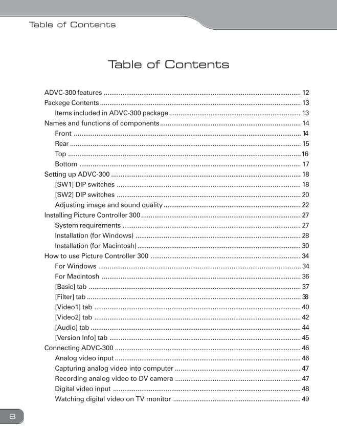
Table of Contents
8
Table of Contents
ADVC-300 features ......................................................................................................... 12
Packege Contents ........................................................................................................... 13
Items included in ADVC-300 package ...................................................................... 13
Names and functions of components........................................................................... 14
Front ......................................................................................................................... 14
Rear ........................................................................................................................... 15
Top ............................................................................................................................16
Bottom ...................................................................................................................... 17
Setting up ADVC-300 ..................................................................................................... 18
[SW1] DIP switches .................................................................................................. 18
[SW2] DIP switches .................................................................................................. 20
Adjusting image and sound quality ......................................................................... 22
Installing Picture Controller 300 ..................................................................................... 27
System requirements ............................................................................................... 27
Installation (for Windows) ........................................................................................ 28
Installation (for Macintosh)....................................................................................... 30
How to use Picture Controller 300 ................................................................................ 34
For Windows ............................................................................................................ 34
For Macintosh .......................................................................................................... 36
[Basic] tab ................................................................................................................. 37
[Filter] tab .................................................................................................................. 38
[Video1] tab .............................................................................................................. 40
[Video2] tab .............................................................................................................. 42
[Audio] tab ................................................................................................................ 44
[Version Info] tab ...................................................................................................... 45
Connecting ADVC-300 ................................................................................................... 46
Analog video input ................................................................................................... 46
Capturing analog video into computer ................................................................... 47
Recording analog video to DV camera ................................................................... 47
Digital video input .................................................................................................... 48
Watching digital video on TV monitor .................................................................... 49

Table of Contents
9
Recording digital video to analog VCR ................................................................... 49
Technical Information .................................................................................................... 50
Priorities among analog input signals ..................................................................... 50
Audio modes ............................................................................................................ 50
Copyright protection feature ................................................................................... 50
Specifications .................................................................................................................51
Troubleshooting ............................................................................................................. 52

10


12
Component analog output is supported via the D1 connector.D1 terminal output
ADVC-300 is compatible with any video format.Input: NTSC, PAL, and SECAM are supported.Output: NTSC and PAL are supported.
Compatible with SECAM format
This product is includes with Picture Controller 300, which lets youadjust the quality of image and sound in a snap from Windows orMacintosh.
Image and sound quality adjustment software
The ADVC-300 outputs color bars for reference signal from analogvideo output. It is handy for making adjustments on images.
* Color bars are not output from DV.
Color bar signal output feature
ADVC-300 has employed the Locked Audio technology, which digi-tizes audio samples keeping the pace with video frame. Because videoand audio data are in sync, the analog audio does not get behind thevideo. You can feel assured that your video and audio stay in sync evenwhen you convert lengthy video contents such as a movie.
Image and sound stay in sync: Locked Audio
The Locked Audio feature is ef-fective only in analog-to-digitalconversion. It does not work indigital-to-digital conversion.
Tip
What is the configuration savefeature?This feature enables the ADVC-300 to save the current configu-ration into the internal Flashmemory when its power is turnedOFF and call up that configura-tion when it is powered nexttime. This feature is utilized forinput modes and other settings.
Tip
ADVC-300 featuresADVC-300 featuresADVC-300 featuresADVC-300 featuresADVC-300 features

13
PPPPPackackackackackage Contentsage Contentsage Contentsage Contentsage ContentsThe product package includes the following accessories.
Items included in ADVC-300 packageItems included in ADVC-300 packageItems included in ADVC-300 packageItems included in ADVC-300 packageItems included in ADVC-300 package
• ADVC-300 • AC adapter and cable
• DV cable (6-pin to 4-pin) • CD-ROM
• ADVC-300 User Manual(this document)
* This programs can be used onlywhen you agree to the contentsof Software End User LicenseAgreement displayed at instal-lation. Be sure to confirm thecontens of End User LicenseAgreement.
As the AC adapter comes in aform that the adapter unit andcable (to receptacle) are sepa-rated each other, connect thembefore using it.
Tip
* The shape of the plug may dif-fer depending on your point ofparchase.

14
Names and functions of componentsNames and functions of componentsNames and functions of componentsNames and functions of componentsNames and functions of components
FrontFrontFrontFrontFront
(1) [INPUT SELET] switchThis switch sets the input mode to either of DV or analog. Theswitch toggles between the following two modes:• Analog > DV > Analog* If the [INPUT SELECT] switch is held down for about 3 seconds, color
bars are output. Pressing the switch once again returns you to the DVinput mode.
(2) [DIGITAL IN] LEDLights while the ADCV-300 is receiving signals from the DV termi-nal and converting them to analog signals.
(3) [ANALOG IN] LEDLights while the ADVC-300 is receiving signals from the analogterminal and converting them to DV signals.
(4) STATUS LEDLights in red when the Macrovision signal or any anomaly hasbeen detected.When the standby feature has been enabled, this LED lights ingreen if the ADVC-300 enters the standby mode.
(5) AUDIO IN L/RTerminal for analog audio input.
(6) VIDEO INTerminal for composite video input.
(7) S-VIDEO INTerminal for S-video input.
(8) DV IN/OUTTerminal for DV connection (4-pin). Connect this terminal to a DVdevice or computer.
(4)(1) (5) (6) (7) (8)
(3)(2)

15
RearRearRearRearRear
(1) (2) (3) (4) (7)
(6)(5)
(1) DV IN/OUTTerminal for DV connection (6-pin). Connect this terminal to a DVdevice or computer.
(2) S-VIDEO OUTTerminal for S-video output.
(3) VIDEO OUTTerminal for composite video output.
(4) AUDIO OUT L/RTerminal for analog audio output.
(5) DC IN 5VConnect the AC adapter that comes with the product to this termi-nal.
(6) [POWER] switchAllows you to turn ON/OFF the ADVC-300.
(7) COMPONENT OUTTerminal for D1 output.
NOTE
Please do not connect DVcamcorders to DV connectors onboth sides at the same time. Thisoperation is not supported.

16
TTTTTopopopopop
(3) (4) (5)(1) (2)
(1) [ADJUST DOWN] switchWhen selecting an item to set up, pressing this switch moves theADJUST LEVEL LED's current indication to the left by one. Whenadjusting the quality of image or sound, pressing this switch de-creases the setting value by one.
(2) [ADJUST UP] switchWhen selecting an item to set up, pressing this switch moves theADJUST LEVEL LED's current indication to the right by one. Whenadjusting the quality of image and sound, pressing this switchincreases the setting value by one.
(3) ADJUST LEVEL LEDShows the value for the image quality setting or sound qualitysetting, etc.
(4) 3D Processing LEDY/C LED
Lights when 3D Y/C separation is activated for processing ana-log composite inputs.* Since S-video inputs come with the luminance (Y) and chrominance
(C) signals separated each other from the start, Y/C separation is notapplied to them and thus this LED does not light.
NR LEDLights when 3D noise reduction is activated.

17
(5) [ENTER] switchUse this switch to acknowledge the setting you made.
BottomBottomBottomBottomBottom
(1)
(2)
(1) [SW1] DIP switchesDIP switches for setting VIDEO and AUDIO modes.
(2) [SW2] DIP switchesDIP switches for making video settings.

18
Setting up ADVC-300Setting up ADVC-300Setting up ADVC-300Setting up ADVC-300Setting up ADVC-300
[SW1] DIP switches[SW1] DIP switches[SW1] DIP switches[SW1] DIP switches[SW1] DIP switchesAllow you to set various modes. No.5, No.6 may differ depending onyour point of parchase.
NOTE
Before changing the DIP switchsettings, be sure to turn thepower OFF.
No.1 PHY Speed settingAllows you to set the PHY Speed. (Usually, set to S400.)
OFF: S400 ON: S200
No.2 Update Mode settingAllows you to set Update Mode. (Usually, set it to Normal.)
OFF: Normal ON: Update
No.3 Locked Audio Mode settingAllows you to select whether to use the Locked Audio mode or not.(Refer to P. 49.)
OFF: Locked ON: Unlocked
No.4 Audio Mode settingAllows you to select audio frequency.
OFF: 48kHz/16bit ON: 32kHz/12bit
No.5 NTSC Setup Level settingAllows you to set the black (setup) level. This switch is effectiveonly in the NTSC format.
OFF: 0 IRE ON: 7.5 IRE (North America, South Korea)
No.6 Video Format settingAllows you to select video signal format.
OFF: NTSC ON: PALWhen both of No.5 NTSC Setup Level and No.6 Video Format are setto ON, the SECAM format is used.* At this time, the SECAM format is used for input and PAL format for
output.

19
No.7 Standby settingAllows you to set whether to use the standby feature (which detectsthe signal coming from devices connected to the DV terminal).
OFF: Disable ON: Enable
* Standby featureThis feature turns ON/OFF the ADVC-300 power automatically af-ter detecting ON/OFF of the power of the device connected to theDV terminal.You can use the [POWER] switch to turn ON/OFF the ADVC-300power as usual even when the standby feature is active.
No.8 Operation Mode settingAllows you to select the control method of ADVC-300.
OFF: UNIT ON: PC
* UNIT modeIn this mode, the ADVC-300 operates standalone, thus all the op-erations are made via the buttons and indicators on it. To set theoperation mode, use the DIP switch for it. You can set up the qual-ity of image and sound on the ADVC-300. This mode is providedfor using the ADVC-300 as a simple DV converter.
* PC modeIn this mode, the ADVC-300 is controlled by a computer connectedto it via the IEEE 1394 interface. Image and sound quality is con-trolled from the computer. The buttons on the ADVC-300 are notoperable in this mode.
NOTE
When you use the standby fea-ture, use either of the DV termi-nal on the front or the one on therear, not both, for connecting yourdevice.
* Depending on the specificationof your device’s (computer’s)DV terminal standby functionor the OHCI card specification,the standby mode may notwork.
Operation ModeThe PC mode and UNIT mode areavailable for your selection.When changing the mode, besure to turn OFF the ADVC-300power before setting the DIPswitch.
Tip

20
[SW2] DIP switches[SW2] DIP switches[SW2] DIP switches[SW2] DIP switches[SW2] DIP switchesAllows you to make video and audio settings.All the switches have been set to OFF at the time of shipment.
No.1 Video Audio Adjust Mode settingAllows you to enable the adjustment on image and sound quality.Usually, set this to [OFF: Normal] (Refer to P. 22).
OFF: Normal ON: Adjust
No.2 Chroma Filter SettingAllows you to select the Chroma filter.
OFF: 1.3 MHz ON: 2.0 MHz
No.3 Component Level settingAllows you to select the component level from SMPTE and BETACAM.
OFF: SMPTE ON: BETACAM
No.4 Aspect Ratio Enable settingAllows you to enable the aspect ratio setting (No.5 Aspect RatioSelect). If set to [OFF: Disable], the aspect ratio of “4:3” is used forD1 output.
OFF: Disable ON: Enable
No.5 Aspect Ratio Select settingAllows you to select the aspect ratio for D1 output.
OFF: 4:3 LetterBox ON: 16:9
No.6 ReservedNot used (Usually, set it to [OFF].)
No.7 ReservedNot used (Usually, set it to [OFF].)
The following functions arechangeable under the PC mode.The set values are saved in theADVC-300's memory.
• Locked Audio Mode([SW1] DIP switch No. 3)
• Audio Mode([SW1] DIP switch No. 4)
The following functions are notchangeable from the PC.
• NTSC Setup Level([SW1] DIP switch No. 5)
• Video Format([SW1] DIP switch No. 6)
• Chroma Filter([SW2] DIP switch No. 2)
• Component Level([SW2] DIP switch No. 3)
• Aspect Ratio Enable([SW2] DIP switch No. 4)
• Aspect Ratio Select([SW2] DIP switch No. 5)
• Video Sync Mode([SW2] DIP switch No. 8)
Tip
21
No.8 Video Sync Mode settingAllows you to select whether to enable the PLL (phase-locked loop)control or not. This switch is effective only for DV inputs.
OFF: External Sync ON: Internal SyncIf set to [OFF: External Sync], the ADVC-300 synchronize the frameand subcarrier period of analog video to be output with the pulses ofthe incoming DV stream. If set to [ON: Internal Sync], the ADVC-300uses its internal circuit to determine the frame period of the analogvideo to be output.
22
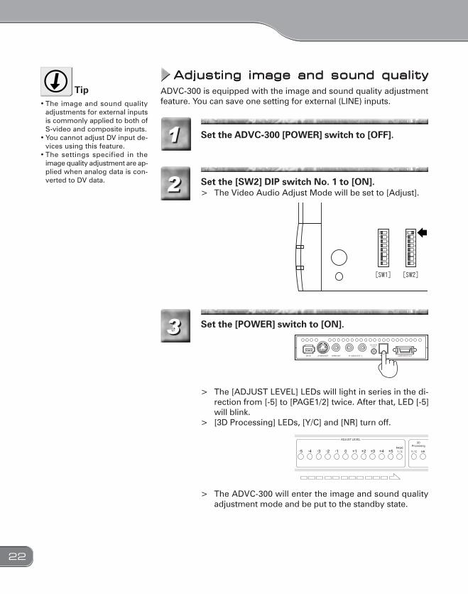
Set the ADVC-300 [POWER] switch to [OFF].
Set the [POWER] switch to [ON].
> The [ADJUST LEVEL] LEDs will light in series in the di-rection from [-5] to [PAGE1/2] twice. After that, LED [-5]will blink.
> [3D Processing] LEDs, [Y/C] and [NR] turn off.
> The ADVC-300 will enter the image and sound qualityadjustment mode and be put to the standby state.
11
3
Set the [SW2] DIP switch No. 1 to [ON].> The Video Audio Adjust Mode will be set to [Adjust].22
3
Adjusting image and sound qualityAdjusting image and sound qualityAdjusting image and sound qualityAdjusting image and sound qualityAdjusting image and sound qualityADVC-300 is equipped with the image and sound quality adjustmentfeature. You can save one setting for external (LINE) inputs.• The image and sound quality
adjustments for external inputsis commonly applied to both ofS-video and composite inputs.
• You cannot adjust DV input de-vices using this feature.
• The settings specified in theimage quality adjustment are ap-plied when analog data is con-verted to DV data.
Tip

23
4 Select your desired item to adjust by pressing the[ADJUST UP] or [ADJUST DOWN] switch.
4To change the page, select[PAGE1/2], and then press the[ENTER] switch. If the page isswitched to page 2, the [PAGE1/2] LED lights up.
Tip
LED Desired item NotePAGE1[-5] Image and sound Default settingPAGE1[-4] Brightness 256 levelsPAGE1[-3] Contrast 256 levelsPAGE1[-2] Hue 256 levelsPAGE1[-1] Saturation 256 levelsPAGE1[ 0] Sharpness 256 levelsPAGE1[+1] Volume 256 levelsPAGE1[+2] Low tone 31 levelsPAGE1[+3] High tone 31 levelsPAGE1[+4] Image Default settingPAGE1[+5] Sound Default settingPAGE1[-5] Y/C separation setting 4 optionsPAGE1[-4] Audio AGC setting 5 levels

24
Press the [ENTER] switch to select the currently cho-sen item
> The [ADJUST LEVEL] LEDs will light in series from [-5] to[PAGE1/2] twice, and then the current setting value (pre-viously saved value) will be indicated.
> PAGE1[-5]: When the image and sound default set-ting has been selected:All the LEDs of [ADJUST LEVEL] and [3DProcessing] will blink at the same time. Pro-ceed to step 7.
> PAGE1[+4]: When the image default setting has beenselected:All the LEDs of [ADJUST LEVEL] will blinkat the same time. Proceed to step 7.
> PAGE1[+5]: When the sound default setting has beenselected:The two LEDs of [3D Processing] will blinkat the same time. Proceed to step 7.
55

25
Adjust the setting value by pressing the [ADJUST UP]or [ADJUST DOWN] switches.66
You can increase or decrease thevalue continuously by holdingdown the [ADJUST UP] or [AD-JUST DOWN] key.
Tip
Brightness Low < Default 128 < HighContrast Low < Default 128 < HighHue Green < Default 128 < Red Saturation Light < Default 128 < DeepSharpness Weak < Default 128 < StrongVolume Low < Default 237 < High
Settablevalues
Setting items
Setting items
Setting items
LED -5
0~
-4
24~
-3
47~
-2
70~
-1
93~
0
116~
1
140~
2
163~
3
186~
4
209~
5
232~255
Low tone Weak < Default 0 < StrongHigh tone Weak < Default 0 < Strong
Settablevalues
LED -5 -4 -3 -2 -1 0 1 2 3 4 5
-15~ -14~ -9~ -6~ -3~ 0 1~ 4~ 7~ 10~ 13~15
Y/C separation setting
Audio AGC setting AGC Level
Y/CLED -5
OFFOFF OFF
2OFF
2D3D1
3D 3D3D3 4
-4 -3 -2 -1
NRAGC Level
If the value for the volume set-ting has been set high, the soundmay be distorted when theADVC-300 processes an inputsource with a high volume level.
Tip
Press the [ENTER] switch to set to the current choice.
> The setting will be updated.> The [ADJUST LEVEL] LEDs will light in series from [-5] to
[PAGE1/2] twice, and then [-5] LED will blink.
77Repeat steps 4 to 7 if you want toset up another item.
Tip

26
Set the ADVC-300 [POWER] switch to [OFF].88
Set the [SW2] DIP switch No. 1 to [OFF].
> The Video Audio Adjust Mode will be set to [Normal].> This completes the setup procedure.
99

27
Installing Picture Controller 300Installing Picture Controller 300Installing Picture Controller 300Installing Picture Controller 300Installing Picture Controller 300
System requirementsSystem requirementsSystem requirementsSystem requirementsSystem requirementsCanopus does not gurantee all system meeting the below require-ments to work accordingly with the ADVC-300.
The following are the minimum requirements for using this product.
Windows• CPU: Pentium III or faster• Memory: 128 MB or more• CD-ROM drive: Required to set up the software.• HDD: 4 MB or more of available space for installing the
software• To use Picture Controller 300, an OHCI (IEEE1394) interface is re-
quired.
Macintosh• CPU: G3 or faster• Memory: 128 MB or more• CD-ROM drive: Required to set up the software.• HDD: 4 MB or more of available space for installing the
software• Your Mac needs a standard FireWire port to use Picture Controller
300.
Computer
Windows• Windows 2000 Professional + SP4• Windows XP Home/Professional Edition + SP1
*DirectX 8 or later is required.
Macintosh• Mac OS X 10.2.7 or later
Supported OS

28
Installation (for Windows)Installation (for Windows)Installation (for Windows)Installation (for Windows)Installation (for Windows)
The following describes the procedure for installing Picture Controller300 on a computer running Windows XP.* You can install Picture Controller 300 without ADVC-300 connected with the
computer.
Insert the “ADVC-300 Applications CD” into the CD-ROM drive.
> The CD-ROM automatically starts up and the installationscreen is displayed.
* When the CD-ROM does not automatically start up, run“ADVC-300 Applications CD” > [PCtrl300] > [Steup.exe].
11Do not remove the “ADVC-300Applications CD” from the CD-ROM drive until the installationis completed.
Tip
Click [Next].22
When the License Agreement is displayed, carefullyread the content and click [Yes] only if you agree tothem. If you do not agree to the License Agreement,click [No] to stop installation and notify our customersupport personnel in writing.* If you do not agree to the License Agreement, you can-
not use this software.
33

29
Click [Next].* If you want to change the folder where the program will
be installed into, click [Browse...] and specify your de-sired folder.
> The installation process starts.
44
Select your desired options and click [Next].
> Be sure to read the readme file since it contains contentnot covered in the manuals.
55
Click [Finish].
> This completes the installation of Picture Controller 300.
66ADVC-300 comes wi th the“ProCoder Demo version”. Whenyou want to install “ProCoderDemo”, run “ADVC-300 Applica-tions CD” > [ProCoder Trial] >[ProCoderDemo_1_25.exe].
Tip

30
Installation (for Macintosh)Installation (for Macintosh)Installation (for Macintosh)Installation (for Macintosh)Installation (for Macintosh)
The following describes the procedure for installing Picture Controller300 on a computer running Mac OS X.* You can install Picture Controller 300 without ADVC-300 connected with the
computer.
Insert the “ADVC-300 Applications CD” into the CD-ROM drive.> The [ADVC300] icon will appear.
11Do not remove the “ADVC-300Applications CD” from the CD-ROM drive until the installationis completed.
Tip
Run [ADVC300] > [PCtrl300] > [Picture Controller300.pkg].
> The installer starts up.
22
Enter your name and password, and then click [OK].33

31
Click [Continue].44
Read the content carefully, and click [Continue].> Be sure to read the readme file since it contains content
not covered in the manuals.
55

32
Click [Continue].
> The License Agreement will be displayed.
Read the content carefully and click [Agree] only ifyou agree to it.> If you do not agree to the License Agreement, click [Dis-
agree] to stop installation and notify our customer sup-port personnel in writing.
* If you do not agree to the License Agreement, you can-not use this software.
66
Select the destination folder for installation, and thenclick [Continue].77

33
Click [Install].
> The installation process starts.
88
After the installation completes, click [Close].
> The [Picture Controller 300] folder is created in the [Ap-plications] folder.
99
34
How to use Picture Controller 300How to use Picture Controller 300How to use Picture Controller 300How to use Picture Controller 300How to use Picture Controller 300NOTE
Do not turn ON/OFF the ADVC-300 power when the computerconnected to the ADVC-300 via aDV cable is OFF or in a standbymode.
Picture Controller 300 lets youadjust the image and sound qual-ity of streams coming from thecomputer via the DV terminal.These settings are effective evenafter the ADVC-300 is turned OFFor disconnected from the com-puter.
Tip
FFFFFor Windowsor Windowsor Windowsor Windowsor WindowsNOTE
When the ADVC-300 power isOFF, set the [SW1] DIP switch No.8 to [ON: PC] (PC mode) before-hand (Refer to P.19).
Connect the ADVC-300 to the computer, boot up thecomputer, and set the [POWER] switch to [ON].11

35
Click the [Start] menu, point to [All Programs], andclick [Canopus Picture Controller 300].
> Picture Controller 300 will start up.
22• About Picture Controller 300
setup screen (Refer to P. 37 to45)[Open Preview] ([Close Pre-view]) button
Opens the preview screen(closes the preview screen).
[Default] buttonReverts the setting to the de-fault.
[OK] buttonSaves the current setting andexits Picture Controller 300.
[Cancel] buttonExits Picture Controller 300without saving the current set-ting.
Tip

36
FFFFFor Macintoshor Macintoshor Macintoshor Macintoshor Macintosh
Connect the ADVC-300 to the computer, boot up thecomputer, and set the [POWER] switch to [ON].11
NOTE
When the ADVC-300 power isOFF, set the [SW1] DIP switch No.8 to [ON: PC] (PC mode) before-hand (Refer to P.19).
Click [Picture Controller 300] in the [Picture Control-ler 300] folder.
> Picture Controller 300 will start up.
22• About Picture Controller 300
setup screen (Refer to P. 37 to45)[Preview] button
Opens the preview screen.[Default] button
Reverts the setting to the de-fault.
[Restore] buttonRestores the previously savedsetting.
• Picture Controller 300 setupitems for Windows and the onesfor Macintosh are identical.* Screenshots of tab pages
shown in this manual are theones for Windows.
Tip

37
[Basic] tab[Basic] tab[Basic] tab[Basic] tab[Basic] tab
This tab page is provided for adjusting the image and sound quality.
• Image SettingAllows you to adjust the brightness, contrast, saturation, hue, andsharpness of your video.
• Audio SettingAllows you to adjust the volume, high and low tones and AGC gainof video.
Audio Setting: AGC gainThe sound volume is automati-cally adjusted by this feature. Youcan set the level of AGC automaticadjustment.
Tip

38
[Filter] tab[Filter] tab[Filter] tab[Filter] tab[Filter] tab
This tab page is provided for setting up Y/C separation and DNR.
NOTE
When the S-video input, Y/Cseparation of the [Filter] tab cannot set.
• Video Processing[Y/C Separation 2D]
When displaying composite video, the ADVC-300 separates theluminance (Y) and chrominance (C) signals based on the scan-ning lines above and below.
[Y/C Separation 3D]When displaying composite video, the ADVC-300 compares thecurrent frame with the previous one using the Motion Detectioncircuit and separates Y/C signals in the areas determined to bestill images. In this mode, Y/C signals are separated more effec-tively than in the 2D mode.

39
• 3D Noise ReductionRemoves noise from each of the luminance (Y) and chrominance(C) signals after comparing the current frame with the previous one.[Y Signal]
Allows you to set the noise reduction level for the luminance (Y)signal.
[C Signal]Allows you to set the noise reduction level for the chrominance(C) signal.
• 2D Noise ReductionRemoves noise by blurring the entire image uniformly by using thebuilt-in filter.[Y Signal]
Allows you to set the noise reduction level for the luminance (Y)signal.
[C Signal]Allows you to set the noise reduction level for the chrominance(C) signal.
• 3D Y/C Separation[Motion Detection]
Allows you to adjust the sensitivity of the Motion Detection cir-cuit when [Y/C Separation 3D] has been selected.
Digital 3D Y/C separationThe composite signal is a mix of the lu-minance (Y) and chrominance (C) sig-nals. To compress the composite signalto the DV format, the luminance (Y) andchrominance (C) signals needs to beseparated each other. For doing thisseparation, two methods are available.• 2D Y/C separation
In this method, Y/C signals are sepa-rated using the vertical relationship ofa dot. Although this method producescolor noise when a dot has little rela-tionship with the upper and lower dotssuch as the case of a slanted white lineon the black background, it is widelyaccepted recent years because thismethod can work with a higher resolu-tion screen.
• 3D Y/C separationIn this method, Y/C signals are sepa-rated based on the time relationshipof dots displayed at the same spot. Thismethod enables you to obtain thehighest quality of image among theavailable methods today. In thismethod, still pictures, which havestrong relationship in the time axis, areprocessed using the time axis, and mo-tion pictures, which have weak rela-tionship in the time axis, are processedusing the relationship with the scan-ning lines above and below (2 dimen-sions.). This method requires a digitalframe buffer and motion detectionmechanism.
Digital 3D Noise ReductionIn a conventional method, noise is re-duced by lowering the frequency char-acteristics for the entire picture (blurring)in one or two-dimensions. This methodhas a problem in affecting other partsnot containing noise. The digital 3Dnoise reduction feature employed byADVC-300, however, removes noiseafter detecting noise using the charac-teristic of noise (noise has little relationto others in the time axis), the adverteffect to the image is kept minimal.* Because of the construction, it is not auniversal solution for all noises.
Tip

40
[Video1] tab[Video1] tab[Video1] tab[Video1] tab[Video1] tab
This tab page is provided to set the correction for color graduation. Ifthis correction is enabled for a video having black or white crushes, thevideo is adjusted and become clear and crisp.
• Black ExpansionCorrects grayish black by correcting the gain of black (low bright-ness) areas and thereby enhancing their blackness.[Adjustment]
Allows you to set the level of black expansion. The higher thevalue, the deeper the black will be.
[Base Level]Allows you to specify up to which level of brightness you want toenhance the black. The more the cursor is moved to the right, thehigher (brighter) the bright level will be.
[Auto Adjust]Adjusts the level of black expansion based on the average bright-ness of the incoming video.
We recommend setting this to[Middle] or [Strong] because youmay not recognize the effect ofthis setting if it has been set to[Weak].
Tip
NOTE
If the cursor is set to the far rightwhen [Adjustment] has been setto [Weak] or [Middle], the screenimage may become whitish be-cause of insufficient correction.

41
• White Peak AdjustCorrects a whiteout image by correcting the gain of white (highbrightness) areas and thus restoring the contrast in them.[Adjustment]
Allows you to set the level of white peak adjustment. The higherthe level, the lower the white peak will be.
[Base Level]Allows you to specify up to which level of brightness you want tocorrect the white peak. The more the cursor is moved to the left,the lower (darker) the bright level will be.
[Auto Adjust]Adjusts the level of white peak based on the average brightnessof the incoming video.
• White StepLowers the luminance signal level when the incoming video has ahigher level of the average brightness to enhance the reproducibil-ity of graduation in brighter areas.[Base Level]
Allows you to specify up to which level of brightness you want tolower the luminance signal as correction. The more the cursor ismoved to the left, the lower (darker) the bright level will be.
[Adjustment]Adjusts the level of white graduation correction based on theaverage brightness of the incoming video.
This feature is effective for im-ages with white spreading overthe screen.
Tip

42
[Video2] tab[Video2] tab[Video2] tab[Video2] tab[Video2] tab
This tab page is provided to sets up the edge correction and AGC.
• Edge AdjustmentCorrects the edge of human or object profiles in videos.[Horizontal Edge]
Corrects horizontal edges in video. Vertical edges are thus en-hanced.
[Vertical Edge]Corrects vertical edges in video. Horizontal edges are thus en-hanced.

43
• Video AGCSets up the AGC feature for video in detail. Checkmark this option ifyou want to automatically set the brightness of the entire video toan optimal level.[AGC]
If [Auto] is checkmarked, the brightness of the entire video willbe automatically adjusted. When [Fix] is checkmarked, the bright-ness of the entire video will be adjusted using the fixed value.
[Set Auto Gain]Allows you to set the automatic adjustment level of AGC if [AGC]has been set to [Auto]. The more the cursor is moved to the right,the higher the level for AGC will be, thereby making the videoless bright.
[Y Adjust]Allows you to set the fixed brightness level of AGC if [AGC] hasbeen set to [Fix], The more the cursor is moved to the right, themore (brighter) the gain will be.
AGC is an acronym of “Auto GainControl” and the function to auto-matically adjust the image gradu-ation and such. Using this feature,you can always display the videoin an optimal brightness leveleven if the video input to displaychange every time.
Tip

44
[Audio] tab[Audio] tab[Audio] tab[Audio] tab[Audio] tab
Sets the sampling rate and the Locked Audio mode.
• Audio Encode[Locked audio mode]
Allows you to select whether to use the Locked Audio mode ornot.
[Sampling Rate]Allows you to select an audio frequency.
[48kHz 16bit]Audio data will be processed as 16-bit stereo sound at 48 kHz.Select this option when you want to create DVD videos.
[32kHz 12bit]Audio data will be processed as 4-channel 12-bit data at 32 kHz.ADVC-300 processes only the main 2 channels and no sound isrecorded in the 2 sub-channels.
This setting cannot be altered inthe UNIT mode.
Tip
NOTE
This switch is effective only foranalog inputs.

45
[V[V[V[V[Version Info] tabersion Info] tabersion Info] tabersion Info] tabersion Info] tab
This tab page shows the version information of Picture Controller 300.

46
Connecting ADVC-300Connecting ADVC-300Connecting ADVC-300Connecting ADVC-300Connecting ADVC-300
Analog video inputAnalog video inputAnalog video inputAnalog video inputAnalog video inputMake connections between devices as shown in the figure.NOTE
Before connecting/disconnectinga DV cable, be sure to turn OFFthe power of your computer andADVC-300.
Computer DV cameraReceptacle
*When both of the video and S-video terminals are used, the S-video terminal takes priority.
Audiooutput
VCR DVD drive
Input
Input
Input
TV monitor
Videooutput
S videooutput
Connect either of the cables.
AC adapter
OutputOutput
Front
4pin 6pin
6pin
DV
ADVC-300
DV
4pin
Rear
47
Capturing analog video into computerCapturing analog video into computerCapturing analog video into computerCapturing analog video into computerCapturing analog video into computerNOTE
Do not turn ON/OFF the ADVC-300 power when the computerconnected to the ADVC-300 via aDV cable is OFF or in the standbymode. Otherwise, your computermay become unbootable depend-ing on the OHCI card being used.In this instance, disconnect theADVC-300 from the computertemporarily, turn OFF and ON thepower of the computer, and thenconnect the ADVC-300 to thecomputer again.
Press the [POWER] switch on the rear.11
By pressing the [INPUT SELECT] switch on the front,switch the input mode to the ANALOG IN externalinput mode.> The ANALOG IN LED will light.
22
Playback the video you want to capture on the ana-log VCR.33
Capture the video on your computer.> For how to capture the video on your computer, consult
the user's manual of the software you are using.
44Audio sampling frequency duringcapturingIn Line input selection: You canselect from 48 kHz (16-bit) and32 kHz (12-bit). Select this set-ting using the DIP switch or “Pic-ture Controller 300”.
Tip
Recording analog video to DV cameraRecording analog video to DV cameraRecording analog video to DV cameraRecording analog video to DV cameraRecording analog video to DV camera
Press the [POWER] switch on the rear.11
By pressing the [INPUT SELECT] switch on the front,switch the input mode to the ANALOG IN externalinput mode.> The ANALOG IN LED will start light.
22
Put the DV camera in the record pause mode.33
Playback the video you want to copy on the analogVCR.44
Release the pause button of the DV camera.> The analog video will be copied to the DV camera.55
48
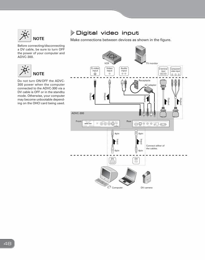
Digital video inputDigital video inputDigital video inputDigital video inputDigital video inputMake connections between devices as shown in the figure.NOTE
Before connecting/disconnectinga DV cable, be sure to turn OFFthe power of your computer andADVC-300.
Computer DV camera
Receptacle
Audioinput
Videoinput
S videoinput
Connect either of the cables.
VCR TV monitor
D terminalinput
Componentvideo input
Input
Outp
ut
Outp
ut
Output
Outp
ut
Outp
ut
Input
Front Rear
DV
6pin
4pin 6pin
ADVC-300
4pin
DV
AC adapter
NOTE
Do not turn ON/OFF the ADVC-300 power when the computerconnected to the ADVC-300 via aDV cable is OFF or in the standbymode. Otherwise, your computermay become unbootable depend-ing on the OHCI card being used.

49
WWWWWatching digital video on TV monitoratching digital video on TV monitoratching digital video on TV monitoratching digital video on TV monitoratching digital video on TV monitor
Press the [POWER] switch on the rear.11
By pressing the [INPUT SELECT] switch, switch theinput mode to DIGITAL IN.> The DIGITAL IN LED will light.
22
Output your desired digital video from the computer(or DV camera).> The digital video will be displayed on the TV monitor.* For how to output digital video on your computer, con-
sult the user’s manual of the software you are using.
33
Recording digital video to analog VCRRecording digital video to analog VCRRecording digital video to analog VCRRecording digital video to analog VCRRecording digital video to analog VCR
Press the [POWER] switch on the rear.11
By pressing the [INPUT SELECT] switch, switch theinput mode to DIGITAL IN.> The DIGITAL IN LED will light.
22
Put the analog VCR in the record pause mode.33
Playback the video you want to copy on the DV cam-era.44
Release the pause button of the analog VCR.> The digital video is recorded to the analog VCR.55

50
TTTTTechnical Informationechnical Informationechnical Informationechnical Informationechnical Information
Priorities among analog input signalsPriorities among analog input signalsPriorities among analog input signalsPriorities among analog input signalsPriorities among analog input signalsWhen all the connectors are used at the same time, priority is given inthe order shown below:
• Video1. S-video input2. Composite input
48kHz/16-bit modeIn this mode, audio data is recorded as 16-bit stereo sound at 48 kHz.Select this option when you create DVD videos.
32kHz/12-bit modeIn this mode, 4 channels of 12-bit audio signals are recorded at 32kHz.When ADVC-300 is used for recording, audio data is recorded in onlythe 2 main channels and no sound is recorded in the 2 sub-channels.
Unlocked modeUnlocked audio in consumer products are allowed to have somedeviation in the number of audio samples per one video frame. If thisdeviation is accumulated along with elapsed time, however, it re-sults in sound drift. On the other hand, the Locked Audio mode en-sures synchronization between audio and video by restricting thenumber of audio samples per one video frame in accordance with apreset pattern, thereby sound drift does not take place. When theLocked Audio mode is used for capturing from a video source withhighly irregular signals such as game machines, however, the re-corded sound may contain noises because incoming signals exceedthe limit for regulating the number of audio samples in accordancewith the locked audio pattern. For that reason, we made the Un-locked mode available for your use.
Audio modesAudio modesAudio modesAudio modesAudio modes
Copyright protection featureCopyright protection featureCopyright protection featureCopyright protection featureCopyright protection featureThis product supports copyright protection technologies such as copy-prevention technology. If the ADVC-300 receives data with copy-pre-vention signals attached, it outputs the data with extremely low bright-ness and contrast. The STATUS LED will light to indicate this.

51
SpecificationsSpecificationsSpecificationsSpecificationsSpecificationsVideo signal formats NTSC(0IRE), NTSC(7.5IRE), SECAM*, PALDV 4-pin iLINK ConnectorFront terminals
6-pin iLINK ConnectorRear terminalsAnalog Video S-Video(MiniDIN 4 Pin)x1
RCA jack Compositex1Front terminal Input
S-Video(MiniDIN 4 Pin)x1RCA jack Compositex1
Rear terminal Output
Analog Audio 48kHz 16bit 2ch32kHz 12bit 4ch(ADVC-300 processes only the main 2 channelsand not other 2 sub-channels.)
Data
RCA jack x2(L/R)Front terminal InputRCA jack x2(L/R)Rear terminal Output
Component video D connector (D1) x 1Rear terminal OutputPower supply AC adapter
Power consumption Max. 9W0.5W in the standby mode
External dimensions (excluding protrusions) 146 (W) x 27.2 (H) x 175 (D)Weight 430g
* When the SECAM format is used, the SECAM format is used just for inputs, and PAL is used for analog videooutputs.
Ambient temperature 0 to 45oC

52
TTTTTroubleshootingroubleshootingroubleshootingroubleshootingroubleshootingIf you have found any troubles, check the following points before con-tacting us for repair.
Symptoms Cause/Action
Pressing the POWERswitch does turn ONthe ADVC-300 power.
> Check that the AC adapter is connected tothe DC IN 5V connector and the receptacle.
Video and audio arenot output.
> Check if the POWER switch is ON. Checkthat this product and DV/analog devicesare properly connected.
It cannot record. > If the video input or audio data containscopyright protection signals, it cannot berecorded properly.
Color bars are not dis-played.
> The [INPUT SELECT] switch needs to bepressed for 3 seconds or more without abreak.
The buttons on theADVC-300 are not op-erable.
> The mode selection [SW1] DIP switch No.8 is set to ON. In this mode, the ADVC-300 is operable only from the computer.

53

54F157311042