cansat2015_3976_cdr_v02
TRANSCRIPT

Team Logo
Here
1
CanSat 2015
Critical Design Review (CDR)Version 2.0TEAM 3976
NEBULA
CanSat 2015 CDR: Team 3976 NEBULA

Team Logo
Here
(If You Want)
2
Presentation Outline
Presenter: Osman Mirza Demircan CanSat 2015 CDR: Team 3976 (NEBULA)
• System Overview - Osman Mirza Demircan
• Sensor Subsystem Design - Fırat Dağkıran
• Descent Control Design - Ahmet Serkan Altınok
• Mechanical Subsystem Design - Osman Mirza Demircan
• Communication and Data Handling Design - Fırat Dağkıran
• Electrical-Power Subsystem Design - Fırat Dağkıran
• Flight Software Design - Ahmet Bayram
• Ground Control System - Muhammed Ali Kul
• CanSat Integration and Test - Gamze Gökmen
• Mission Operations & Analysis - Kutay Çetin
• Requirements Compliance - Gamze Gökmen
• Management - Muhammed Ali Kul

Team Logo
Here
(If You Want)
3
Team Organization
CanSat 2015 CDR: Team 3976 (NEBULA)Presenter: Osman Mirza Demircan
Surname Name Department Year of Study
Aktaş Rozerin Computer Engineering Sophomore
Altınok Ahmet Serkan Aeronautical Engineering Junior
Bayram Ahmet Astronautical Engineering Junior
Çetin Kutay Aeronautical Engineering Junior
Dağkıran Fırat Electrical & Electronics Engineering Junior
Demir Oğuzhan Aeronautical Engineering Junior
Demircan Osman Mirza Aeronautical Engineering Junior
Gökmen Gamze Astronautical Engineering Junior
Kul Muhammed Ali Astronautical Engineering Junior
Yıldız Ahmet Astronautical Engineering Freshman
All members are undergraduate students at the University of Turkish Aeronautical Asssociation.

Team Logo
Here
(If You Want)
4
Team Organization
CanSat 2015 CDR: Team 3976 (NEBULA)
Team Lead
Osman Mirza Demircan
Mechanical Systems Lead
Osman Mirza Demircan
Ahmet Serkan Altınok
Oğuzhan Demir
Ahmet Yıldız
Electronics & Flight Software Lead
Fırat Dağkıran
Ahmet Bayram
Rozerin Aktaş
Mission Operations &
System Testing Lead
Gamze Gökmen
Osman Mirza Demircan
Kutay Çetin
Telecommunication &
Ground Station Lead
Muhammed Ali Kul
Ahmet Bayram
Faculty Advisor
Assoc. Prof. Nevsan Şengil
Logistics Management
Muhammed Ali Kul
Presenter: Osman Mirza Demircan

Team Logo
Here
(If You Want)
5
Acronyms
Presenter: Osman Mirza Demircan CanSat 2015 CDR: Team 3976 (NEBULA)
• A : Analysis
• ADC : Analog Digital Converter
• ALT : Altitude
• C : Container
• CAM : Video Camera
• CDH : Communication and Data Handling
Requirement
• D : Demonstration
• DCR : Descent Control System Requirement
• DCS : Descent Control System
• EEPROM : Electronically Erasable Programmable Read-
Only Memory
• EPR : Electrical Power System Requirement
• EPS : Electrical Power System
• FSR : Flight Software Requirement
• FSW : Flight Software
• GCS : Ground Control System Requirement
• GS : Ground Station
• I : Inspection
• I2C : Inter-Integrated Circuit
• MCU : Microcontroller
• MR : Mechanical System Requirement
• P : Payload
• PDR : Preliminary Design Review
• PFR : Preflight Review
• PRM : Payload Release Mechanism
• RTC : Real-Time Clock
• RF : Radio Frequency
• SEN : Sensor Subsystem Requirement
• SPI : Serial Peripheral Interface
• SR : System Requirement
• T : Test
• VM : Verification Method

Team Logo
Here
6
System Overview
Osman Mirza DEMİRCAN
CanSat 2015 CDR: Team 3976 (NEBULA)

Team Logo
Here
(If You Want)
7
Mission Summary
CanSat 2015 CDR: Team 3976 (NEBULA)Presenter: Osman Mirza Demircan
• Mission Objectives– Simulating a payload* traveling through a planetary atmosphere sampling and sending
telemetry data to the ground during descent.
– Separating the payload from the container** at the right moment.
– Recording the descent of the payload in the nadir.
– Preventing the video image from rotating more than 90 degrees.
– Storing telemetry and video image for recovery and inspection after landing.
– Transporting an egg*** inside the payload.
– Assuring the safety of the container, the payload and its components from launch tolanding.
• Bonus ObjectiveSelection: Using a three-axis accelerometer to measure the stability and angle of descent ofthe payload. Sampling at appropriate rate and store data for later retrieval.
Rationale: It will tell us the descent velocity ters of the science vehicle and give an idea aboutits stability parameters.
• External ObjectiveAcquiring the needed experience for future projects of Nebula Space Systems Society.
* «The science vehicle» is simply referred to as «the payload» throughout this CDR
** «The re-entry container» is simply referred to as «the container» throughout this CDR
*** «The large raw hen’s egg» is simply referred to as «the egg» throughout this CDR

Team Logo
Here
(If You Want) Summary of Changes Since PDR
• Container body is reinforced with better structure
• Payload structure is modified for better area usage and functionality
• 4 more blades are considered for the autogyro mechanism
• Stability rod is removed
• Placement of the egg has changed
• Electronics are not all together anymore
• Placement of each electronic component is decided
• Major FSW codes are finished and tested
• Manufacturing processes are decided and explained
• Testing environments are decided and explained
• Most of the CanSat components are ordered
• University’s lab equipments are at our disposal
• Sponsorship applications started
8CanSat 2015 CDR: Team 3976 (NEBULA)Presenter: Osman Mirza Demircan

Team Logo
Here
(If You Want) System Requirement Summary
9CanSat 2015 CDR: Team 3976 (NEBULA)Presenter: Osman Mirza Demircan
ID Requirement Rationale Priority ChildrenVM
A I T D
SR01Total mass of the CanSat (Container and Science Vehicle) shall
be 600 grams +/- 10 grams not including the egg.
Competition
RequirementHigh X X
SR02
The Science Vehicle shall be completely contained in the
Container. No part of the Science Vehicle may extend beyond
the Container.
Competition
RequirementHigh MR01 X
SR03
The Container shall fit in the envelope of 125 mm x 310 mm
including the Container passive descent control system.
Tolerances are to be included to facilitate Container deployment
from the rocket fairing.
Competition
RequirementHigh MR02 X
SR04
The Container shall use a passive descent control system. It
cannot free fall. A parachute is allowed and highly
recommended. Include a spill hole to reduce swaying.
Competition
RequirementHigh DCR01 X
SR05 The Container shall be a florescent color, pink or orange.Competition
RequirementLow X
SR06The rocket air frame shall not be used to restrain any
deployable parts of the CanSat.
Competition
Requirement High X
SR07The rocket air frame shall not be used as part of the CanSat
operations.
Competition
RequirementHigh X X
SR08The CanSat (Container and Science Vehicle) shall deploy from
the rocket payload section.
Competition
RequirementHigh X

Team Logo
Here
(If You Want) System Requirement Summary
10CanSat 2015 CDR: Team 3976 (NEBULA)Presenter: Osman Mirza Demircan
ID Requirement Rationale Priority ChildrenVM
A I T D
SR09
The Container or Science Vehicle shall include electronics and
mechanisms to determine the best conditions to release the
Science Vehicle based on stability and pointing. It is up to the
team to determine appropriate conditions for releasing the
Science Vehicle.
Competition
RequirementHigh SEN01 X X X X
SR10
The Science Vehicle shall use a helicopter recovery system.
The blades must rotate. No fabric or other materials are allowed
between the blades.
Competition
RequirementHigh DCR02 X X
SR11All electronic components shall be enclosed and shielded from
the environment with the exception of sensors.
Competition
RequirementLow MR04 X
SR12All electronics shall be hard mounted using proper mounts such
as standoffs, screws, or high performance adhesives.
Competition
RequirementHigh MR07 X X
SR13All mechanisms shall be capable of maintaining their
configuration or states under all forces.
Competition
RequirementHigh MR08 X
SR14 Mechanisms shall not use pyrotechnics or chemicals.Competition
RequirementHigh X
SR15
Mechanisms that use heat (e.g., nichrome wire) shall not be
exposed to the outside environment to reduce potential risk of
setting vegetation on fire.
Competition
RequirementMedium X

Team Logo
Here
(If You Want) System Requirement Summary
11CanSat 2015 CDR: Team 3976 (NEBULA)Presenter: Osman Mirza Demircan
ID Requirement Rationale Priority ChildrenVM
A I T D
SR16
During descent, the Science Vehicle shall collect and telemeter
air pressure (for altitude determination), outside and inside air
temperature, flight software state, battery voltage, and bonus
objective data (accelerometer data and/or rotor rate).
Competition
RequirementHigh
SEN02
FSR01X X X X
SR17
XBEE radios shall be used for telemetry. 2.4 GHz Series 1 and
2 radios are allowed. 900 MHz XBEE Pro radios are also
allowed.
Competition
RequirementHigh X X
SR18Cost of the CanSat shall be under $1000. Ground support and
analysis tools are not included in the cost.
Competition
RequirementHigh X
SR19 Each team shall develop their own ground station.Competition
RequirementMedium GCS01 X X X
SR20The Science Vehicle shall hold one large raw hen’s egg which
shall survive launch, deployment and landing.
Competition
RequirementHigh X X X
SR21Both the Container and Science Vehicle shall be labeled with
team contact information including email address.
Competition
RequirementLow X X
SR22 No lasers are allowed.Competition
RequirementHigh X
Team Logo
Here
(If You Want)
12
System Concept of Operations
CanSat 2015 CDR: Team 3976 (NEBULA)Presenter: Osman Mirza Demircan
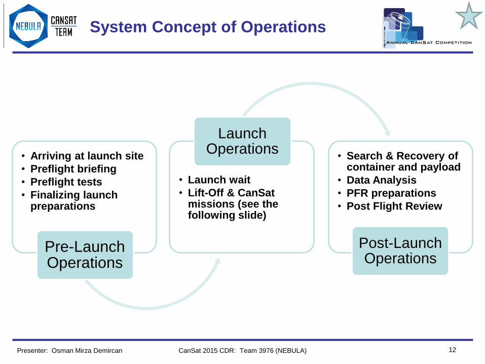
• Arriving at launch site
• Preflight briefing
• Preflight tests
• Finalizing launchpreparations
Pre-LaunchOperations
• Launch wait
• Lift-Off & CanSat missions (see thefollowing slide)
LaunchOperations
• Search & Recovery of container and payload
• Data Analysis
• PFR preparations
• Post Flight Review
Post-LaunchOperations

Team Logo
Here
(If You Want)
13
System Concept of Operations
CanSat 2015 CDR: Team 3976 (NEBULA)Presenter: Osman Mirza Demircan

Team Logo
Here
(If You Want)
14
Physical Layout: Container
CanSat 2015 CDR: Team 3976 (NEBULA)Presenter: Osman Mirza Demircan
Container Interface
Body Frame
Parachute
Air Inlets
PRM Connection
Payload Compartment
Cover Membrane
All dimensions are in millimeters.

Team Logo
Here
(If You Want)
15
Physical Layout: Payload
CanSat 2015 CDR: Team 3976 (NEBULA)Presenter: Osman Mirza Demircan
All dimensions are in millimeters.
Payload Interface
PRM
Autogyro Mechanism
Body Frame
Cover Membrane
Primary Electronics Compartment
Egg Compartment
Power Supply Compartment
Secondary Electronics Compartment

Team Logo
Here
(If You Want)
16
Physical Layout: CanSat
CanSat 2015 CDR: Team 3976 (NEBULA)Presenter: Osman Mirza Demircan
CanSat Interface
Container DCS
PRM
Payload DCS
Payload Compartments
Cover membranes are not shown.
All dimensions are in millimeters.

Team Logo
Here
(If You Want)
17
Physical Layout: CanSat Integrated
CanSat 2015 CDR: Team 3976 (NEBULA)Presenter: Osman Mirza Demircan
All dimensions are in millimeters.
Rocket Nose Cone
CanSat Integrated Configuration
(Upside Down)

Team Logo
Here
(If You Want)
18
Launch Vehicle Compatibility
CanSat 2015 CDR: Team 3976 (NEBULA)Presenter: Osman Mirza Demircan
• The payload and its subsystems are designed to be placed
upside down inside the rocket’s payload section. The main
reason behind this choice was to ease the deployment of the
container’s parachute.
• Rocket payload : Height = 310mm Diameter = 125mm
• CanSat dimensions : Height = 300mm Diameter = 115mm
• As can be seen on the visual representation of how the
integration will look like, our design fits inside the payload
section with margins of 5mm. We kept this value a bit small
intentionally in order to prevent the CanSat to move too much
during ascent which could cause damage.
• To verify the rocket payload section compatibility, the
dimensions of both the CanSat and the rocket are going to be
checked for any protrusions and any necessary action will be
taken during preflight tests.
All dimensions are in millimeters.

Team Logo
Here
19
Sensor Subsystem Design
Fırat DAĞKIRAN
CanSat 2015 CDR: Team 3976 (NEBULA)

Team Logo
Here
(If You Want)
20
Sensor Subsystem Overview
Presenter: Fırat Dağkıran CanSat 2015 CDR: Team 3976 (NEBULA)
Sensor Type Model Purpose(Measurement) Placement
Pressure Sensor BMP180 • Altitude Payload
Temperature Sensor BMP180 • Inside Temperature Payload
Temperature Sensor LM35CZ • Outside Temperature Payload
3-Axis Accelerometer ADXL345• Stability parameters
• Velocity calculationPayload
Voltage Sensor PH–1135 • Voltage Payload

Team Logo
Here
(If You Want) Sensor Changes Since PDR
21CanSat 2015 CDR: Team 3976 (NEBULA)
• Sensor Addition: LM35CZ
– More suitable physical structure to integrate on CanSat for outside temprature measurement
compared to BMP180
– Faster adaptation to temperature changes compared to BMP180
– Wider range compared to BMP180 (-55 – 150 °C Degree)
– Very low self heating 0.08 °C degrees in still air
Presenter: Fırat Dağkıran

Team Logo
Here
(If You Want)
22
Sensor Subsystem Requirements
CanSat 2015 CDR: Team 3976 (NEBULA)
ID Requirement Rationale Priority Parent ChildrenVM
A I T D
SEN01
The Container or Science Vehicle shall include
electronics and mechanisms to determine the best
conditions to release the Science Vehicle based on
stability and pointing. It is up to the team to
determine appropriate conditions for releasing the
Science Vehicle.
Safety of the
MissionHigh SR09 X X X X
SEN02
During descent, the Science Vehicle shall collect
and telemeter air pressure (for altitude
determination), outside and inside air temperature,
flight software state, battery voltage, and bonus
objective data (accelerometer data and/or rotor
rate).
Competition
RequirementHigh SR16 FSR01 X X X X
SEN03• 1 meter resolution
• Sampling rate greater of than 1Hz
Competition
RequirementMedium X
SEN04• 1 Celcius degree resulotion
• Sampling rate of greater then 1Hz
Competition
RequirementMedium X
SEN05• 1g/LSB resolution
• Sampling rate of greater than 1 Hz
Competition
RequirementMedium X
Presenter: Fırat Dağkıran

Team Logo
Here
(If You Want)
23
Altitude Sensor Summary
CanSat 2015 CDR: Team 3976 (NEBULA)
Selected Sensor: BMP180
• Accuracy down to 0.02 hPa in advanced resolution mode.
• Range is between 300–1100 hPa.
• Data interface is I2C. Provides 19 bits pressure value.
• Pressure change of ΔP = 1hPa, corresponds to 8.43m at sea level.
• Altitude calculating procedure shown below;
• From the ideal gas equation, we can say that the change in air temperature affects the
atmospheric pressure. That effect is known as ‘Density Altitude’ and it has effect on pressure
measurement.
• To perform pressure reading, we’ll first take temperature reading, then we’ll combine that with
a raw pressure reading to come up with a final temperature-compensated pressure
measurement. Then we’ll calculate altitude with the following formula;
- p is the calculated pressure value.
- p0 is pressure at sea level (1013.25 hPa ).
- p0 will be the initial pressure where the GS is.
StartStart Temperature
MeasurementRead UT
Start Pressure
MeasurementRead UP
Calculate Pressure
and Temperature In
Physical Units
Presenter: Fırat Dağkıran

Team Logo
Here
(If You Want)
24
Air Temperature Sensor Summary
CanSat 2015 CDR: Team 3976 (NEBULA)
– Selected Sensor: BMP180• Selected to measure temperature inside the paylaod.
• Calculation of temperature in steps of 0.1 Celcius Degree.
• It’ll provide 16 bits measurement.
• For temperature calculating in 0.1 Celcius Degree accuracy, calibration must received from
the EEPROM. Procedure is shown below;
– Selected Sensor: LM35CZ• Selected to measure temperature outside the payload.
• Wide temperature range ( -55˚C to 150˚C ).
• Draws only 91.5µA from the power supply.
• Suitable physical structure for integration.
• Transfer function will be used to calculate temperature value shown below;
Presenter: Fırat Dağkıran

Team Logo
Here
(If You Want)
25
Camera Summary
CanSat 2015 CDR: Team 3976 (NEBULA)
• Selected Camera: OV7670
• Power comsumption provides one hour of recording.
• It will be stabilized by the autogyro mechanism.
• The image shouldn’t rotate more than +/- 90 degrees.
• It is going to have a timestamp provided by FSW.
TypeVoltage
Required
Current
Consumption
Power
Consumption
Video
OutputSensitivity
OV7670 3.3 V 12mA 5mW RGB 1.3 Lux
Presenter: Fırat Dağkıran

Team Logo
Here
(If You Want)
26
3-Axis Accelerometer Sensor
Trade & Selection
CanSat 2015 CDR: Team 3976 (NEBULA)
• Selected sensor: ADXL345
Rationale:
– Acceptable frequency
– Easy communication
– Suitable range
– Adequate resolution
Sensor Range Resolution Frequency Communication Protocol
ADXL345 ± 16g 0.03 g/LSB <1MHz SPI or I2C
MMA8653 ± 8g 0.015g/LSB <1MHz I2C
BMA140 ± 4g 0.002g/LSB <1MHz Analog
Presenter: Fırat Dağkıran

Team Logo
Here
27
Descent Control Design
Ahmet Serkan ALTINOK
CanSat 2015 CDR: Team 3976 (NEBULA)

Team Logo
Here
(If You Want)
28
Descent Control Overview
CanSat 2015 CDR: Team 3976 (NEBULA)Presenter: Ahmet Serkan Altınok
1
2
3
4
Container DCS
Elements
Payload DCS
Elements
Parachute with spill hole Blades (4x2)
Air inlets (x8) Hubs (x2)
Hollow Shaft
Descending process1. After CanSat is deployed from the rocket at about 600
meters of height from the ground, the container’s parachute
should deploy passively with the airflow coming through to
air inlets.
2. Until the CanSat descends down to 500 meters of height,
the PRM is going to wait for the accelerometer’s
stabilization signal to release the payload.
3. However, It should definitely activate when the height is
below 500 meters using the data from FSW.
4. After the release, the blades of the payload should
passively open and start rotating in reverse direction,
slowing down the payload to a constant descent rate before
it reaches 300 meters. While the payload is descending,
this autogyro mechanism will keep it stabilized for better
image acquisition.

Team Logo
Here
(If You Want)
29
Descent Control Changes Since
PDR
CanSat 2015 CDR: Team 3976 (NEBULA)
• Parachute radius is increased by 3 cm due to safety
concerns
• Number of blades are increased to 8
• Stability rod is removed due to manufacturing
considerations and increase in number of blades
• Prototype tests will begin on April 18th
Presenter: Ahmet Serkan Altınok

Team Logo
Here
(If You Want)
30
Descent Control Requirements
CanSat 2015 CDR: Team 3976 (NEBULA)
ID Requirement Rationale Priority Parent ChildrenVM
A I T D
DCR01
The Container shall use a passive descent control
system. It cannot free fall. A parachute is allowed
and highly recommended. Include a spill hole to
reduce swaying.
Competition
RequirementHigh SR04 X
DCR02
The Science Vehicle shall use a helicopter recovery
system. The blades must rotate. No fabric or other
materials are allowed between the blades.
Competition
RequirementHigh SR10 X X
DCR03All descent control device attachment components
shall survive 50 Gs of shock.
Safety of the
MissionHigh X X
DCR04All descent control devices shall survive 50 Gs of
shock.
Safety of the
MissionHigh X X
DCR05
The descent rate of the Science Vehicle shall be
less than 10 meters/second and greater than 4
meters/second.
Competition
RequirementHigh X X X
DCR06
During descent, the video camera must not rotate.
The image of the ground shall maintain one
orientation with no more than +/- 90 degree rotation.
Competition
RequirementMedium X X X
Presenter: Ahmet Serkan Altınok

Team Logo
Here
(If You Want)
31
Container Descent Control
Hardware Summary
• Container does not contain any electronics
• Parachute will be hand made using parachute fabric. It
will include gores, shroud lines and a spill hole to reduce
swaying
• Parachute will open by air diffusion from air inlets
• We made air inlets as big as possible to stay safe
• We will test the parachute after manufacturing by blowing
air from below to see if it works, then we will test the drag
created by parachute
• Container cover membrane will be fluorescent orange
CanSat 2015 CDR: Team 3976 (NEBULA)Presenter: Ahmet Serkan Altınok

Team Logo
Here
(If You Want)
32
Payload Descent Control Hardware
Summary
CanSat 2015 CDR: Team 3976 (NEBULA)
• Payload will be deployed when the container gets
stabilized
• Stabilization is measured by FSW, if there is almost no
acceleration in 2 directions and acceleration in vertical
direction is close to the gravitational acceleration for 3
seconds, payload will be deployed
• If stabilization does not occur when the cansat reaches
500 meters, FSW will deploy the payload anyways
Presenter: Ahmet Serkan Altınok
Team Logo
Here
(If You Want)
33
Payload Descent Control Hardware
Summary
CanSat 2015 CDR: Team 3976 (NEBULA)
• Deployment will occur by activating the PRM on top of
the autogyro mechanism
• Payload is slowed down to around 8 m/s by using 8
coaxial blades
• Blades are white since they will be made from polyamide
• Blades will have carbon fiber rods as spars inside them
to increase their structural properties
Presenter: Ahmet Serkan Altınok

Team Logo
Here
(If You Want)
34
Descent Rate Estimates
CanSat 2015 CDR: Team 3976 (NEBULA)
Container + Payload post separation (prior to deployment of the Payload)
• It is obtained that if a radius of 18 cm is used for parachute, velocity of container
+ payload above 500m altitude will be approximately calculated as follows.
• 𝐹 = 0 ∶ 𝑚𝑔 = 0.5 × 𝜌 × 𝑉𝑐2 × 𝐶𝐷 × 𝜋 × 𝑟
2
• 𝑉𝑐 =2×𝑚×𝑔
𝐶𝐷×𝜌×𝜋×𝑟2
• Total mass=0.6 kg
• Air density is assumed constant and 𝜌 = 1.1673 𝑘𝑔/𝑚3 @ 500 meters
• 𝐶𝐷 = 1.25 for semi-hemispherical shaped parachute canopy
• Since radius of parachute is 0.18 cm, terminal velocity is calculated as
𝑉𝑐 = 8.9 𝑚/𝑠
Container following deployment of the Payload
• Parachute is also going to descend the container after seperation. Velocity of
container is calculated in a similar manner as follows.
• 𝐹 = 0 ∶ 𝑚𝑔 = 0.5 × 𝜌 × 𝑉𝑐2 × 𝐶𝐷 × 𝜋 × 𝑟
2
• 𝑉𝑐 =2×𝑚×𝑔
𝐶𝐷×𝜌×𝜋×𝑟2
• Total mass of container = 0.092 kg
• Air density is assumed constant and 𝜌 = 1.1673 𝑘𝑔/𝑚3 @ 500 meters
• 𝐶𝐷 = 1.25 for hemispherical shaped parachute
• Since radius of parachute is 0.18 cm, terminal velocity is calculated as
𝑉𝑐 = 2.9 𝑚/𝑠
𝐹𝑑𝑟𝑎𝑔
W=mg
Presenter: Ahmet Serkan Altınok

Team Logo
Here
(If You Want)
35
Descent Rate Estimates
CanSat 2015 CDR: Team 3976 (NEBULA)
Payload following separation from the Container
• To satisfy DCR 05, the payload should decend with a velocity between 4 m/s and 10 m/s. In
order to create an assistant force to body drag, blades are used since they will create lift.
Also to prevent rotational movement of payload, blades are placed as in a similar manner to
helicopter rotors. Lift coming from the blades and drag occuring from body will be in the
same direction which is negative to direction of descent of payload. These forces will
decelerate the payload until the net force exerting on payload i.e., acceleration of the
system will become zero.
• 8 blades are used and placed 4 by 4. Qblade software is used to specify the airfoil type,
blade shape and dimensions.
• 𝐹 = 0 ∶ 𝑚𝑔 = 8 ∗ 𝐿𝑖𝑓𝑡 𝑜𝑓 𝑒𝑎𝑐ℎ 𝑏𝑙𝑎𝑑𝑒 + (0.5 × 𝜌 × 𝑉𝑐2 × 𝐶𝐷 × (𝐹𝑟𝑜𝑛𝑡𝑎𝑙 𝐴𝑟𝑒𝑎 𝑜𝑓 𝑃𝑎𝑦𝑙𝑜𝑎𝑑))
• Mass of payload = 0.533 kg (max. mass stated at mass budget section of this CDR)
• Air density is assumed constant and 𝜌 = 1.225 𝑘𝑔/𝑚3
• 𝐶𝐷 = 1.2 for rectangular prism
• Frontal area of payload = 𝑎2 = 0.006 𝑚2 where a is length of an edge
• Desired terminal velocity interval 4 𝑚/𝑠 < 𝑉𝑐 < 10𝑚/𝑠
• Necessary lift production of each blade is going to be determined according to terminal
velocity.
• Characteristics of blade and airfoil used is given in the following slide.
𝐹𝑑𝑟𝑎𝑔 + 𝐹𝑙𝑖𝑓𝑡
W=mg
Presenter: Ahmet Serkan Altınok

Team Logo
Here
(If You Want)
36
Descent Rate Estimates
CanSat 2015 CDR: Team 3976 (NEBULA)
Blade Design• 8 identical blades are going to be used in order to produce the required lift
• Designed elementary and simple in manufacturing
Airfoil Design
Characterics of Blades• Chord length = 3cm
• Span = 16cm
• Hub radius = 4cm
• Airfoil = S-808
• Tip speed ratio = 7
• Twist angle = 12 degrees
Presenter: Ahmet Serkan Altınok

Team Logo
Here
(If You Want)
37
Descent Rate Estimates
CanSat 2015 CDR: Team 3976 (NEBULA)
Payload following separation from the Container
• Obtained values of Qblade showed that maximum 𝐶𝐿 that can be produced is 1.2. By using this value for calculations,
terminal velocity is determined as follows.
• 𝐹 = 0 ∶ 𝑚𝑔 = 8 ∗ 𝐿𝑖𝑓𝑡 𝑜𝑓 𝑒𝑎𝑐ℎ 𝑏𝑙𝑎𝑑𝑒 + (0.5 × 𝜌 × 𝑉𝑐2 × 𝐶𝐷 × (𝐹𝑟𝑜𝑛𝑡𝑎𝑙 𝐴𝑟𝑒𝑎 𝑜𝑓 𝑃𝑎𝑦𝑙𝑜𝑎𝑑))
• Mass of payload = 0.533 kg
• Air density is assumed constant and 𝜌 = 1.225 𝑘𝑔/𝑚3
• 𝐶𝐷 = 1.2 for rectangular prism
• Frontal area of payload = 𝑎2 = 0.006 𝑚2 where a is length of an edge
• Cross sectional area of one blade = 0.01 𝑚2
• Lift =0.5 × 𝜌 × 𝑉𝑐2 × 𝐶𝐿 × 𝐴𝑏𝑙𝑎𝑑𝑒
• 𝐶𝐿 = 1.2
• Desired terminal velocity interval 4 𝑚/𝑠 < 𝑉𝑐 < 10𝑚/𝑠
• Terminal velocity is determined as approximately 8 m/s.
• Considering real life case, payload will continue its fall approximately between 7.5-8.5 m/s.
Presenter: Ahmet Serkan Altınok

Team Logo
Here
38
Mechanical Subsystem Design
Osman Mirza DEMIRCAN
CanSat 2015 CDR: Team 3976 (NEBULA)

Team Logo
Here
(If You Want)
39
Mechanical Subsystem Overview
CanSat 2015 CDR: Team 3976 (NEBULA)Presenter: Osman Mirza Demircan
Structural
componentContainer Payload
Longitudinal
framesx4 x4
Formers x4 x1
Horizontal Plates x1 x4
Material Polyamide Polyamide
Mass (gr) 47.0±0.1 51.1±0.1
Shape Cylindrical Square prism
Compartments x2 x4
Container Elements Payload Elements
Parachute
compartment (1)Autogyro connection (3)
Air inlets x8Primary electronics
compartment (4)
PRM connection Egg compartment (5)
Payload
compartment (2)
Power supply compartment
(6)
Secondary electronics
compartment (7)
13
4
5
6
7
2

Team Logo
Here
(If You Want)
Mechanical Subsystem
Changes Since PDR: Container
40CanSat 2015 CDR: Team 3976 (NEBULA)Presenter: Osman Mirza Demircan
Change Rationale
One more former is added to the body frame Increasing overall stiffness to maintain shape
Top former is thinner Assisting parachute deployment by widening deployment hole
4 big air inlets on the sides and 4 other on the horizontal plate
instead of 8 small ones on the cover membraneAssisting parachute deployment by increasing air flow rate
Top part of the body is not covered, but made part of the body Better maintain the shape of the air inlets
Bottom part of the body is filled Preventing payload to get stuck during payload deployment
PDR PDRCDR CDR

Team Logo
Here
(If You Want)
Mechanical Subsystem
Changes Since PDR: Payload
41CanSat 2015 CDR: Team 3976 (NEBULA)Presenter: Osman Mirza Demircan
Change Rationale
Electronics are separated in different compartments Otherwise is not feasible due to the length of the antenna
Instead of 2, 4 compartments are considered: primary
electronics compartment, egg compartment, power supply
compartment, secondary electronics compartment
Better placements in terms of area usage and functionality
2 vertical clearences on each horizontal plate are considered,
one for the cables and one for the antennaConnection between electronics and a way for the antenna
A fluorescent orange colored cover membrane is considered Assisting postflight recovery and protecting components
A former is considered at the bottom instead of a plate, this
part is not covered
Better for both the camera and the antenna, plus, it allows an
open area for measuring air temperature
8 blades instead of 4, stability rod is removed Obtaining required lift to stay between 4-8 m/s
PDR CDR

Team Logo
Here
(If You Want)
42
Mechanical Sub-System
Requirements
Presenter: Osman Mirza Demircan CanSat 2015 CDR: Team 3976 (NEBULA)
ID Requirement Rationale Priority Parent ChildrenVM
A I T D
MR01
The Science Vehicle shall be completely contained in
the Container. No part of the Science Vehicle may
extend beyond the Container.
Competition
RequirementHigh SR02 X
MR02
The Container shall fit in the envelope of 125 mm x
310 mm including the Container passive descent
control system. Tolerances are to be included to
facilitate Container deployment from the rocket
fairing.
Physical
ConstraintsHigh SR03 X
MR03The Container shall not have any sharp edges to
cause it to get stuck in the rocket payload section.
Safety of the
MissionHigh X X
MR04
All electronic components shall be enclosed and
shielded from the environment with the exception of
sensors.
Competition
RequirementLow SR11 X
MR05All structures shall be built to survive 15 Gs
acceleration.
Structural
IntegrityHigh X X
MR06 All structures shall be built to survive 30 Gs of shock.Structural
IntegrityHigh X X
MR07
All electronics shall be hard mounted using proper
mounts such as standoffs, screws, or high
performance adhesives.
Safety of the
ElectronicsHigh SR12 X X
MR08All mechanisms shall be capable of maintaining their
configuration or states under all forces.
Safety of the
MissionHigh SR13 X

Team Logo
Here
(If You Want)
43
Egg Protection Overview
• The egg is going to be secured inside a viscoelastic material
covered with a protective polyamide shell
• The viscoelastic material is chosen as soft rubber, the reason
behind this choice is to provide the required damping and a soft
surface to avoid damaging the egg in any way
• After placing the egg vertically between the rubbers, the rubber
case will be covered horizontally inside the shell. The shell is going
to be fastened to the egg compartment with small plates using
screws/bolts
CanSat 2015 CDR: Team 3976 (NEBULA)Presenter: Osman Mirza Demircan
Egg Covering Process

Team Logo
Here
(If You Want)
Mechanical Layout of Components:
Container
44CanSat 2015 CDR: Team 3976 (NEBULA)Presenter: Osman Mirza Demircan
#Component
NameProperties
1 Body Frame
Subcomponents: Longitudinal frames(x4), horizontal plate(x1),
formers(x4)
Shape: Cylindrical frame structure
Material: Polyamide PA2200
Size: Diameter = 115mm, height = 300mm
2Cover
MembraneMaterial: Thin Cardboard
3 DCS
Subcomponents: Gores(x6), shroud lines(x6), spill hole, eye-bolt(x2)
Shape: Semi-hemispherical (canopy)
Material: Parachute fabric (gores)
Size: Diameter = 16
Parachute fabric
Cover membrane
PRM
connection

Team Logo
Here
(If You Want)
Mechanical Layout of Components:
Payload
45CanSat 2015 CDR: Team 3976 (NEBULA)Presenter: Osman Mirza Demircan
#Component
NameProperties
1 PRM
Subcomponents: Turnigy TGY-
50090M(x1), output arm(x1)
Material: Metal (gear)
2 Autogyro Blades(x4), hollow shaft, hubs
3 Body Frame
Subcomponents: Longitudinal
frames(x4), horizontal plates(x4),
formers(x1)
Shape: Square prism frame structure
Material: Polyamide PA2200
Size: Width = 75mm, height = 164mm
4Cover
MembraneMaterial: Thin Cardboard
5 Electronics
Subcomponents: ADXL345, BMP180,
LM35CZ, Phidgets 1135, OV7670,
Arduino SD Card Module, Arduino
Nano 3.0, Xbee Pro 900 RPSMA, A09-
HASM-675, DS1307, Buzzer
6 Power Supply 9V Duracell Alkaline Battery x2
7 ConnectorsScrews, bolts, fasteners, tape,
cables(electronics)

Team Logo
Here
(If You Want)
Mechanical Layout of Components:
CanSat
46CanSat 2015 CDR: Team 3976 (NEBULA)Presenter: Osman Mirza Demircan
# Component Name
1 Container Body Frame
2 Container Parachute
3 PRM
4 Autogyro Mechanism
5 Payload Body Frame
6 Primary Electronics
7 Egg Protector
8 Batteries
9 Secondary Electronics

Team Logo
Here
(If You Want) Material Selections
47CanSat 2015 CDR: Team 3976 (NEBULA)Presenter: Osman Mirza Demircan
• Polyamide (PA 2200) is chosen as material for all structural elements.
• Although its density is high, this material has exceptional mechanical,
thermal and chemical resistance properties.
• Standard screws and bolts are decided to be used where needed.
• The actuator has metal gears which should resist the stress on it.
• The blades are to be 3D printed but their spars are decided to be carbon
fiber rods to reduce bending due to aerodynamic loading.
Component Name Material
Container Body Frame Polyamide
Container Parachute Parachute Fabric
Autogyro Mechanism Polyamide+Carbon Fiber
Payload Body Frame Polyamide
Egg Protector Rubber+Polyamide

Team Logo
Here
(If You Want)
48
Container - Payload Interface
CanSat 2015 CDR: Team 3976 (NEBULA)Presenter: Osman Mirza Demircan
- Firstly, blades are folded and the payload is placed inside the container’s payload
compartment.
- The upper bars of the actuator are placed such that the payload doesn’t rotate about itself
when the actuator is activated. Then the arm is manually turned to fit in the extruded part of
the horizontal plate separating the two compartments of the container.
PRM PRM

Team Logo
Here
(If You Want)
49
Container - Payload Interface
CanSat 2015 CDR: Team 3976 (NEBULA)Presenter: Osman Mirza Demircan
- This way, the payload stays put until the arm is activated. After this process, the cover
membrane is placed on top of the container.
When the releasing command is given by the FSW, the output arm
turns, releasing the payload.
The container body frame is to be designed such that when the
payload is released, it conducts the payload directly below without
giving it any chance to get stuck.

Team Logo
Here
(If You Want) Structure Survivability
Container:
• The parachute is going to be attached to the container body frame
with eye-bolts
Payload:
• Mounting holes are considered on the horizontal plates for properly
mounting all electronics
• Hard screw mounting method is chosen
• Battery packs are considered for easy change, each battery will also
be secured with fasteners to stay safe
• Primary electronics are enclosed by the body and cover membrane
while other ones such as camera, air temperature sensor and buzzer
are open to atmosphere
• Electric cables are going to be fastened to the payload body frame
keep them in place
50CanSat 2015 CDR: Team 3976 (NEBULA)Presenter: Osman Mirza Demircan

Team Logo
Here
(If You Want) Structure Survivability: Container
51CanSat 2015 CDR: Team 3976 (NEBULA)Presenter: Osman Mirza Demircan
15G Acceleration Test:
(Solidworks Simulation)
Whole structure survives.
Maximum displacement = 0.086mm

Team Logo
Here
(If You Want) Structure Survivability: Payload
52CanSat 2015 CDR: Team 3976 (NEBULA)Presenter: Osman Mirza Demircan
15G Acceleration Test:
(Solidworks Simulation)
Whole structure survives.
Max. displacement = 0.57mm

Team Logo
Here
(If You Want) Manufacturing
53CanSat 2015 CDR: Team 3976 (NEBULA)Presenter: Osman Mirza Demircan
Container body frame, payload body frame and egg container shell are all manufactured using
a laser synthering machine provided by our university with polyamide PA2200 as material.
Payload Body Frame
+ Egg Container
CanSat Body Frame
+ Egg Container
cleaning process

Team Logo
Here
(If You Want)
54
Mass Budget
CanSat 2015 CDR: Team 3976 (NEBULA)Presenter: Osman Mirza Demircan
Container Component Mass(g) Margin Source
Container Body 75 ±1 Weighted
Container DCS 25 ±5 Estimate
Payload Component Mass(g) Margin Source
Payload Body 50 ±1 Weighted
Payload DCS (blades, shaft, hubs) 100 ±10 Estimate
Actuator (servomechanism and output arm) 10 ±1 Hobbyking.com
1 Large Raw Hen’s Egg 60 ±5 Wikipedia.com
Egg Container (protective material and shell) 100 ±10 Estimate
Electronics (microprocessor, sensors, camera, radio etc.) 50 ±1 Datasheet
Printed Circuit Board 10 ±1 Estimate
Batteries (both) 90 ±2 Duracell.com
Radio Antenna 30 ±5 Estimate
Total Mass (egg included) 600±42 grams
Container Mass 100±6 grams
Payload Mass (egg included) 500±36 grams
Additional weigth will be added on the container to satisfy SR01 if necessary.

Team Logo
Here
55
Communication and Data Handling
Subsystem Design
Fırat DAĞKIRAN
CanSat 2015 CDR: Team 3976 (NEBULA)

Team Logo
Here
(If You Want)
56
CDH Overview
CanSat 2015 CDR: Team 3976 (NEBULA)Presenter: Fırat Dağkıran
• Payload: – XBEE Pro 900 RPSMA and A09–HASM–675 (antenna) are used for telecommunication.
– BMP180 to measure altitude and inside temperature of the payload.
– LM35CZ to measure the outside temperature.
– ADXL345 to calculate the velocity and stability parameters of the payload.
– OV7670 to record the descent of the payload.
– Arduino Nano for data transmission and handling.
– SD Card Module to store all sensor data and video image.
– DS1307 to record time after CanSat is powered on.
– Phidgets 1135 for power bus voltage measurement.
There are no electronics on the container
Microcontroller
Sensors
Power Supply
XBEE
(End Device)
Memory Unit
XBEE GCSAntenna
Energy Flow
Data/Control

Team Logo
Here
(If You Want) CDH Changes Since PDR
57CanSat 2015 CDR: Team 3976 (NEBULA)
SubjectPrevious
Component
Selected
ComponentRationale
Change A24–HASM–525 A09–HASM–675 • easy to procure in our country
Presenter: Fırat Dağkıran

Team Logo
Here
(If You Want)
58
CDH Requirements
CanSat 2015 CDR: Team 3976 (NEBULA)
ID Requirement Rationale Priority Parent ChildrenVM
A I T D
CDH01
During descent, the Science Vehicle shall collect
and telemeter air pressure (for altitude
determination), outside and inside air temperature,
flight software state, battery voltage, and bonus
objective data (accelerometer data).
Competition
RequirementHigh SR16
SEN02
FSR01X X X X
CDH02The Science Vehicle shall transmit telemetry at a
1Hz rate.
Competition
RequirementHigh FSR02 X X
CDH03
Telemetry shall include mission time with one
second or better resolution,
which begins when the Science Vehicle is powered
on.
For Setting
Mission TimeHigh X X
CDH04
XBEE radios shall be used for telemetry. 2.4 GHz
Series 1 and 2 radios are allowed. 900 MHz XBEE
Pro radios are also allowed.
Competition
RequirementLow SR17 X X
CDH05XBEE radios shall have their NETID/PANID set to
their team number (decimal).
Distinguish
the team
datas from
other teams’
packets
MediumX X
CDH06 XBEE radios shall not use broadcast mode.Competition
RequirementMedium X X
Presenter: Fırat Dağkıran

Team Logo
Here
(If You Want)
– Arduino Nano has really small size and weight compared to any other microcontroller unit.
– Arduino Nano has enough analog and digital pin for all components.
– Arduino Nano has 5.0V and 3.3V voltage regulator. It will make it easier to handle DC–DC
converter circuit.
Data Interfaces:
Sensor
TypeBMP180 LM35CZ ADXL345
SD Card
ModuleXBEE
OV76
70
DS13
07
I2C
SPI
UART
59
Processor & Memory Selection
CanSat 2015 CDR: Team 3976 (NEBULA)
ProcessorSupply
Voltage(V)
Current
Consumption(mA)
Analog
Pins
Flash
Memory(kb)Speed(MHz)
Arduino Nano +9V 40 8 32 16
Presenter: Fırat Dağkıran

Team Logo
Here
(If You Want)
• Selected Memory: SD Card Module
• For Container : There is no data flow, then no data storage.
• For Payload : 12 000 068 bit equals to 0.0015000085 gigabytes.
And SD card’s capacity is 8 gb
then 8 / 0.0015000085 is equal to
5333.2 seconds or 88.8 minutes.
60
Processor & Memory Selection
CanSat 2015 CDR: Team 3976 (NEBULA)
TypeVoltage
Required
Current
Required
Power
RequiredInterfaces Speed
Memory
Capacity
SD Card
Module3.3 V 100-150mA 500mW Digital(SPI) 200MHz GBs
Sensors Memory
Pressure & Temperature
(BMP180)32 bits/s
Accelerometer (ADXL345) 36 bits/s
Camera (Ov7670) 12 mega bits/s
Presenter: Fırat Dağkıran

Team Logo
Here
(If You Want) Real-Time Clock
61CanSat 2015 CDR: Team 3976 (NEBULA)
• Selected RTC: DS1307 Which is a hardware type.
• Flight Software includes Real Time Clock too so they are going to check each other all the
time to see if there is a problem with the hardware.
• And every packet is going to be stored in the SD card after writing every packet, it can be
read from software if there is any inconsistancy with time.
Presenter: Fırat Dağkıran

Team Logo
Here
(If You Want)
62
Antenna Selection
CanSat 2015 CDR: Team 3976 (NEBULA)
Selected Antenna: A09 – HASM – 675– Proporties
• 900 MHz Frequency
• Half Wave Dipole Articulated
• 2.1 dBi Gain
• Mounting type is connector
• 80 mA current consumption
– Performance Discussion (@9600 bps)
• Transmit power output is between 1mWatt and 1Watt.
• Indoor range up to 22km.(Dipole Antenna)
• Outdoor range up to 64km.(High Gain Antenna)
• Receiver sensitivity is -110 dBm
• RF data rate is 10,000 bps.
– Mass Discussion
• 18 grams which is fairly light.
Presenter: Fırat Dağkıran

Team Logo
Here
(If You Want)
63
Radio Configuration
CanSat 2015 CDR: Team 3976 (NEBULA)
• Radio Requirements
– 2.4 GHz Series 1 and 2 radios are allowed. Also, 900MHz XBEE Pro radios
are allowed.
– XBEE radios shall have their NETID/PANID set to team number.
– Container and payload shall have the same NETID/PANID.
– XBEE radios shall not use broadcast mode.
• Transmission Control
– All radios will be set to API mode
– Ground Station Radio works as a coordinator
– Payload radio programmed as an end device
– Payload radio will be programmed to be in Unicast mode
– Payload radio will have the network ID
Presenter: Fırat Dağkıran

Team Logo
Here
(If You Want)
64
Telemetry Format
CanSat 2015 CDR: Team 3976 (NEBULA)
• What data is included?
- All data obtained from required sensors (air temperature, air pressure, voltage,
acceleration etc.)
- Packet count
- Time
• Data rate of packets?
- One packet of data at every second (1Hz)
• How is data formatted?
- After receiving data from transmitter, GS code will write the data to formatted file.
Then, the data will be plotted by Matlab on the user interface in real time.
- Since the only connection between container and science vehicle is the PRM,
there is no packet transfer to ground station from the container. Examples are
shown on the next slide.
Presenter: Fırat Dağkıran

Team Logo
Here
(If You Want)
65
Telemetry Format
CanSat 2015 CDR: Team 3976 (NEBULA)
Format:
– Science Vehicle:<TEAM_ID(3976)>,<PACKET_COUNT>,<MISSION_TIME>,
<ALT_SENSOR>,<TEMP>,<VOLTAGE>,<FSW_STATE>,<BONUS_ACCELEROMETER>
Example Data Packet:
– Science Vehicle : 3976, 48, 48, 500, 33.5, 3.3, 4, 0.2, 10, 0.7.
3976: Team ID
48: Packet Count
48: Mission Time n Seconds
500: Altitude
33.5: Temperature in Celcius
3.3: Voltage
4: Stabilization (FSW State)
0.2, 10, 07 : Acceleration in x, y, z directions m/s2
Presenter: Fırat Dağkıran

Team Logo
Here
66
Electrical Power Subsystem Design
Fırat DAĞKIRAN
CanSat 2015 CDR: Team 3976 (NEBULA)

Team Logo
Here
(If You Want)
67
EPS Overview
CanSat 2015 CDR: Team 3976 (NEBULA)
• Power Source:
– 9V Alkaline batteries(x2) will be used to provide power to all electronic devices.
• Power Switch
– A slided power switch will be used to enable power flow for the entire EPS system.
• DC–DC Converter
– Arduino Nano has 5.0V and 3.3V voltage regulator on board. It will be used as DC–
DC converter for components.
DIAGRAM:
9V Alkaline
BatterySwitch
3.3V
DC to DC
Converter
(OnBoard)
5.0V
DC to DC
Converter
(OnBoard)
Components
which need
9.0V power
supply
Presenter: Fırat Dağkıran

Team Logo
Here
(If You Want) EPS Changes Since PDR
• No Change.
68CanSat 2015 CDR: Team 3976 (NEBULA)Presenter: Fırat Dağkıran

Team Logo
Here
(If You Want)
69
EPS Requirements
CanSat 2015 CDR: Team 3976 (NEBULA)
ID Requirement Rationale Priority Parent ChidrenVM
A I T D
EPR01
The Science Vehicle shall include an easily
accessible power switch which does not
require removal from the Container for
access. An access hole or panel in the
Container is allowed.
Competition
RequirementMedium X
EPR02
The Science Vehicle must include a battery
that is well secured. (Note: a common cause
of failure is disconnection of batteries and/or
wiring during launch.)
Safety of the
MissionHigh X X
EPR03Lithium polymer cells are not allowed due to
being a fire hazard.Competition
RequirementHigh X
EPR04
Alkaline, Ni-MH, lithium ion built with a metal
case, and Ni-Cad cells are allowed. Other
types must be approved before use.
Competition
RequirementMedium X
Presenter: Fırat Dağkıran

Team Logo
Here
(If You Want)
70
Electrical Block Diagram
CanSat 2015 CDR: Team 3976 (NEBULA)
Slided
Switch
9V Alkaline
Battery
5.0V
DC – DC
Converter
3.3V
DC – DC
Converter
Arduino
Nano
LM35CZ
Sensor
Subsystem
CDH
SystemPRMPH – 1135
• On Arduino
Board
5.0V
DC – DC
Converter
• On Arduino
Board
DS1307
• SD Card Module and OV7670 included in Sensor Subsystem
• DS1307 will not be effected by system reset.
• Sensor Subsystems also include; BMP180,ADXL345
• CDH System include XBEE Radio Module
• Led will be used to control power ON/OFF status
Data/Control
Energy Flow
Presenter: Fırat Dağkıran

Team Logo
Here
(If You Want)
Payload Power Source
Selection and Design
71CanSat 2015 CDR: Team 3976 (NEBULA)
Battery Voltage(V)Nominal
Capacity(mAh)Size(mm) Weight(g) Cost
Duracell
Alkaline Battery x29 1200 48.5x26.5x17.5 90 $6.99
• Selected battery: 9V Duracell Alkaline
• Reason Selected:• Suitable size and weight for our CanSat.
• Enough nominal capacity as mAh for our CanSat.
• Used for only payload.
• Easy to find.
• All batteries will be covered with the payload cover membrane.
• Batteries will be easily accesable from outside for changing.
• Batteries will be connect to each other as parallel, so the nominal capacity will doubles.
• For safety, batteries will be connected different points on same bus. If one battery’s connection is
broken other battery can handle the entire system.
Presenter: Fırat Dağkıran

Team Logo
Here
(If You Want)
72
Power Budget
CanSat 2015 CDR: Team 3976 (NEBULA)
Component Current(mA) Voltage(V) Power(mW)Expected Duty
Cycle(min)
Total Energy
Consumed(mWh)Source
BMP180 0.65 3.3 2.145 5 0.178 Datasheet
LM35CZ 0.0915 9.0 0.823 5 0.068 Datasheet
DS1307 1.5 5.0 7.5 5 0.625 Datasheet
XBEE 210 3.3 693.0 5 57,75 Datasheet
SD Car Module 150 3.3 495 5 41.25 Datasheet
ADXL345 0.04 3.3 0.132 5 0.011 Datasheet
OV7670
Camera10.0 3.3 33 5 2.75 Datasheet
Arduino Nano 40.0 9.0 360 5 30 Datasheet
Precision
PH–1135 3.6mA 5.0V 18 5 15 Datasheet
• Total Power Consumption: 147.632 mWh for 5 minutes. (worst case scenario)
• Battery Nominal Capacity: 7200 mWh
• Minimum Life Time: 4.4 Hours
• Excess energy will be stored in capacitor.
Presenter: Fırat Dağkıran

Team Logo
Here
(If You Want)
73
Power Bus Voltage Measurement
CanSat 2015 CDR: Team 3976 (NEBULA)
• PH–1135 sensor will be used for voltage measurement
– Sensor measures differential voltage between the input terminals and outputs the difference
proportionally.
– The maximum differential voltage that can be measured accurately is +/-30V.
– This sensor is able to measure the differential voltage of +/-10V with a CMR of 40V while keeping
the accuracy within 2%.
– The best accuracy can be achieved by using a 2 or more point calibration of system - effectively
calibrating the 1135.
– Using RawSensorValue in the formula will increase the resolution, which is limited by SensorValue
to about 67mV.
– The formula to translate SensorValue into differential voltage is as follows:
where Vdiff defined as Vpositive – Vnegative.
Presenter: Fırat Dağkıran

Team Logo
Here
74
Flight Software (FSW) Design
Ahmet BAYRAM
CanSat 2015 CDR: Team 3976 (NEBULA)

Team Logo
Here
(If You Want)
75
FSW Overview
Presenter: Ahmet Bayram CanSat 2015 CDR: Team 3976 (NEBULA)
• Basic FSW architecture
• Programming languages
- C/C++
• Development environments
- Arduino IDE
FSW
ACTUATOR
STORAGE
GCS
SENSORS

Team Logo
Here
(If You Want)
76
FSW Overview
Presenter: Ahmet Bayram CanSat 2015 CDR: Team 3976 (NEBULA)
• FSW tasks
- Communication between Payload; sensors, mechanisms
and Ground Control Station via transmiting telemetry data at 1
Hz rate. There are no electronics in the container, thus no
electric connection between container and payload. The only
physical connection between container and payload is the
PRM which is controlled by the FSW.
- During flight; recording video, calculating altitude, controlling
descent, seperating Container and Payload and storing all the
data taken from sensors and camera.

Team Logo
Here
(If You Want) FSW Changes Since PDR
• There has been no change in the software plan.
77CanSat 2015 CDR: Team 3976 (NEBULA)Presenter: Ahmet Bayram

Team Logo
Here
(If You Want)
78
FSW Requirements
CanSat 2015 CDR: Team 3976 (NEBULA)Presenter: Ahmet Bayram
ID Requirement Rationale Priority Parent ChidrenVM
A I T D
FSR01
During descent, the Science Vehicle shall
collect and telemeter air pressure (for
altitude determination), outside and inside
air temperature, flight software state,
battery voltage, and bonus objective data
(accelerometer data and/or rotor rate).
Competition
RequirementHigh SR16
SEN02
CDH01X X X X
FSR02The Science Vehicle shall transmit
telemetry at a 1 Hz rate.Competition
RequirementHigh CDH02 X X
FSR03
Telemetry shall include mission time with
one second or better resolution, which
begins when the Science Vehicle is
powered on.
Competition
RequirementHigh CDH03 X X
FSR04
XBEE radios shall have their
NETID/PANID set to their team number
(decimal).
Competition
RequirementMedium CDH05 X X
FSR05XBEE radios shall not use broadcast
mode.Competition
RequirementMedium CDH06 X X

Team Logo
Here
(If You Want)
79
FSW Requirements
CanSat 2015 CDR: Team 3976 (NEBULA)Presenter: Ahmet Bayram
ID Requirement Rationale Priority Parent ChidrenVM
A I T D
FSR06
The Science Vehicle shall have a video camera
installed and recording the complete descent from
deployment to landing. The video recording can
start at any time and must support up to one hour
of recording.
Competition
RequirementMedium X X X
FSR07
The video camera shall include a time stamp on the
video. The time stamp must work from the time of
deployment to the time of landing.
Competition
RequirementMedium X X X
FSR08
The CanSat flight software shall maintain and
telemeter a variable indicating its operating state. In
the case of processor reset, the flight software shall
re-initialize to the correct state either by analyzing
sensor data and/or reading stored state data from
non-volatile memory. The states are to be defined
by each team. Example states include:
PreFlightTest(0), LaunchWait(1), Ascent(2),
RocketDeployment(3), Stabilization(4),
Separation(5), Descent(6), and Landed(7).
Competition
RequirementMedium X X X X
FSR09Data will be stored using an external memory
module through SPI protocol.
Additional
Memory Unit In
Case of Need
Medium X X
FSR10All telemetry data will be displayed and plotted in
real-time during launch and descent.
Competition
RequirementMedium X X X X

Team Logo
Here
(If You Want)
Yes
No
For Payload:
80
CanSat FSW State Diagram
CanSat 2015 CDR: Team 3976 (NEBULA)Presenter: Ahmet Bayram
Start Reading Sensors and Set Initial Altitude Power on
Start Recovery Mode and
Exit Code
Is the altitude greater than 500 m ? Is the Cansat stabilized in x and z
direction ?
Release Container and Science
Vehicle
Continue reading sensors and
store
Yes
No
No Yes
Sample, Store and Transmit
Telemetery Data
Are the past 3 altitude measurements
within our altitude resolution
No
Yes
Is the altitude => 100 m ? Are the
last 2 altitude
measurements decreasing?

Team Logo
Here
(If You Want)
81
CanSat FSW State Diagram
CanSat 2015 CDR: Team 3976 (NEBULA)Presenter: Ahmet Bayram
For Payload :
• BMP180(Pressure and Temperature):
– Communication between microcontroller via I2C interface.
– It requires 1 micro-Amper current.
• XBEE(Telemetry Transmition):
– Communication between transceiver and microcontroller is via serial
interface called USART.
– XBEE will be used as a transmitter. Operating voltage is 3.3V and current
required from the power system is 210mA.
• SD CARD Module (Data Storage):
– Communication between Arduino Nano isvia SPI.
– Its operating speed is 200 MHz.
– The current required is 100-150mA.

Team Logo
Here
(If You Want)
82
CanSat FSW State Diagram
CanSat 2015 CDR: Team 3976 (NEBULA)Presenter: Ahmet Bayram
For Payload :
• ADXL345(Accelerometer):
– Communication is via SPI or I2C interface.
– Current required is 0.14 mA.
– Resolution is 0.03 g/LSB.
• PH 1135(Voltage Measurement):
– Current required is 3.6mA.
– Typical error is ±0.7%.
• OV7670(Camera):
– Communication is via SPI.
– Current required is 12mA.
– Video output is RGB

Team Logo
Here
(If You Want)
83
CanSat FSW State Diagram
CanSat 2015 CDR: Team 3976 (NEBULA)Presenter: Ahmet Bayram
For Container:
• Since all the container roles are passive, there is no need for electronics then no
need for software. Container descent is expected to happen as described in the
Descent Control System Review.
• At the desired altitude, the PRM is going to be triggered for separation process.
Safely descend
Wait for air inlet
Open the parachute

Team Logo
Here
(If You Want)
84
CanSat FSW State Diagram
CanSat 2015 CDR: Team 3976 (NEBULA)Presenter: Ahmet Bayram
• In case of any Microprocessor reset possibility, SD card data are going to
be always checked with the next sensor data(see example below)

Team Logo
Here
(If You Want)
85
Software Development Plan
CanSat 2015 CDR: Team 3976 (NEBULA)Presenter: Ahmet Bayram
PROCESS DETAIL DATE CHECK
Designing an algorithm Most important part 08.28.2014 DONE
Arduino Uno Test Led using breath effect 09.15.2014 DONE
SD Card Module Test 1Reading and writing data(only
text)
09.15.2014 DONE
APC220 Radio Transmission tests 09.16.2014 DONE
Telemetery Data Data Packet Formation 09.16.2014 DONE
LM35DZ TestsTemperature tests and selection
of the correct sensor
10.05.2014 DONE
MPX4115A TestsPressure tests and selection of
the correct sensor
10.05.2014 DONE
MMA7361L Tests
Accelerometer tests and
selection of the correct sensor
for bonus.
10.05.2014 DONE
Altitude Data Tests For testing resolution 10.05.2014 DONE

Team Logo
Here
(If You Want)
86
Software Development Plan
CanSat 2015 CDR: Team 3976 (NEBULA)Presenter: Ahmet Bayram
PROCESS DETAIL DATE CHECK
PDR Preparation 02.10.2015 DONE
ADXL345 Acceleration test 03.21.2015 DONE
CDR Preparation 03.23.2015 DONE
Arduino Nano Test 1 Pin Check 03.25.2015 -
Real Time Clock Tests Comparison with satellite datas 03.25.2015 -
Arduino Nano Test 2 Led using breath effect 03.26.2015 -
Camera Test Capturing video 03.29.2015 -
XBEE Radio Test Data transmission 04.05.2015 -
SD Card Module Test 2Capturing video and writing to
sd card.04.10.2015 -
Servo Motor Test Checking the response 04.12.2015 -
Arduino Nano Test 3 Reset 04.25.2015 -
Buzzer Tests Landing check 05.05.2015 -

Team Logo
Here
(If You Want)
87
Software Development Plan
CanSat 2015 CDR: Team 3976 (NEBULA)Presenter: Ahmet Bayram
• General view of CanSat Software Algorithm

Team Logo
Here
(If You Want)
88
Software Development Plan
CanSat 2015 CDR: Team 3976 (NEBULA)Presenter: Ahmet Bayram
• The SD Card Module is tested by writing and reading data.

Team Logo
Here
(If You Want)
89
Software Development Plan
CanSat 2015 CDR: Team 3976 (NEBULA)Presenter: Ahmet Bayram
• ADXL345 is tested by applying giving an acceleration to the system and
writing data to SD Card(successful).

Team Logo
Here
(If You Want)
90
Software Development Plan
CanSat 2015 CDR: Team 3976 (NEBULA)Presenter: Ahmet Bayram
• Software development began early in development of our CanSat; some
software tests are done and the remaining will be done when a new
sensor or a part of system is ready. Software planning will be developed
in order of: Altitude sensing, radio transmitting, separation commands
and then the bonus objective.
• After finishing coding any component, we will consult academicians at
our university. Debugging with them to gain acceleration.
• Development Team: Ahmet BAYRAM, Rozerin AKTAŞ

Team Logo
Here
91
Ground Control System (GCS) Design
Muhammed Ali KUL
CanSat 2015 CDR: Team 3976 (NEBULA)

Team Logo
Here
(If You Want)
92
GCS Overview
CanSat 2015 CDR: Team 3976 (NEBULA)Presenter: Muhammed Ali Kul
• The antenna is connected to the XBEE Pro 900 RPSMA
• XBEE is connected to the computer via a serial port
• A MATLAB script will read the data, save it into a CSV file, and then
plot it in real time.
Payload Antenna RadioComputerSerial Port
MATLAB Script
(Computer)
PayloadPanel Antenna
XbeeUSB Adaptor (XBee
Explorer Dongle)Computer
Antenna Cable

Team Logo
Here
(If You Want) GCS Changes Since PDR
93CanSat 2015 CDR: Team 3976 (NEBULA)Presenter: Muhammed Ali Kul
• The software has been updated for a better aspect of
interface, effectiveness and ease to read, plot, and save
data.
– The software were written in MATLAB R2012a, now we
have rewritten them using MATLAB R2014a.
– Less time consuming commands have replaced the old
ones.
– The interface is more visual.
– Some bugs have been fixed.

Team Logo
Here
(If You Want)
94
GCS Requirements
Presenter: Muhammed Ali Kul CanSat 2015 CDR: Team 3976 (NEBULA)
ID Requirement Rationale Priority Parent ChidrenVM
A I T D
GCS01 Each team shall develop their own ground station.Competition
RequirementMedium SR19 X X X
GCS02All telemetry shall be displayed in real time during
descent.
Competition
RequirementHigh X X
GCS03All telemetry shall be displayed in engineering units
(meters, meters/sec, Celsius, etc.)
Competition
RequirementMedium X
GCS04Teams shall plot data in real time during flight on the
ground station computer.
Competition
RequirementMedium X X
GCS05
The ground station shall include one laptop computer
with a minimum of two hours of battery operation,
XBEE radio and a hand held or table top antenna.
Competition
RequirementMedium X
GCS06
The ground station shall be portable so the team can
be positioned at the ground station operation site
along the flight line. AC power will not be available at
the ground station operation site.
Competition
RequirementHigh X

Team Logo
Here
(If You Want)
95
GCS Antenna
CanSat 2015 CDR: Team 3976 (NEBULA)Presenter: Muhammed Ali Kul
– HG-8909P Panel antenna will be used for our ground
station.
Name Gain Frequency VSWR Antenna Type
HG-8909P 9dBi 900 MHz <1.8:1 avg. Panel
– This antenna was chosen for several reasons:
• Greater range than the Omni-Directional antennas
• Wider beam angle then Yagi antennas
• Heavy duty all weather plastic radome
• Can be installed for vertical or horizontal polarization
• Includes tilt and swivel mast mount
• Ease of buying and finding in the area where we live

Team Logo
Here
(If You Want)
96
GCS Antenna
CanSat 2015 CDR: Team 3976 (NEBULA)Presenter: Muhammed Ali Kul
GS Antenna Design
ᶿAntenna
• Antenna will be mounted on an beam
which will have 4 legs for stability and 4
clearly marked wires will be planted to
the ground. The antenna will be on the
mid-top point (Shown figure right).
• Ground antenna will be tilted by 34
degrees (ᶿ).
• 3.90 meter height beam, 315 mm to 315
mm Panel antenna, the total force for the
ropes to carry will be 104 N (for the 4
ropes) and it is well in the safe
circumstances. For the best suitable
placement 4.9 m length rope with 35
degrees to the top vertical plane will be
enough. For this configuration, almost any
5mm diameter nylon rope will be resistant
for the safe load up to 60kph wind.

Team Logo
Here
(If You Want)
97
GCS Antenna
CanSat 2015 CDR: Team 3976 (NEBULA)Presenter: Muhammed Ali Kul
ᶿ
Approx. 900m max.
Approx. 600m max.
CanSat
Antenna
• Antenna mast will have 4 legs and 4 clearly
marked rope which are connected to the
ground to stabilize and support properly to
preserve the configuration.
• Antenna and the mast will be tested based on
calculation made before to ensure the safety
under extreme conditions and wind up to
60kph.
• Antenna will be elevated 3.90 meters
approximately.
• Antenna will be connected to the XBEE with a
shielded cable, then to the computer via a
serial port with the dongle connected directly
to it. (Total shielded cable length: 5 meters)
• Antenna mast will be selected such that it will
be suitable for ease transport, easy to
transplant and lightweight, and also strong
enough to resist weather conditions to ensure
safety.

Team Logo
Here
(If You Want)
98
GCS Antenna
CanSat 2015 CDR: Team 3976 (NEBULA)Presenter: Muhammed Ali Kul
• Distance link predictions and margins:
– Assuming that maximum altitude will be 900 meters, and maximum
drift away will lead 600 meters distance horizontally. Hypotenuse of
this assumption (which is total distance from receiver to the CanSat)
is around 1100 meters.
• So we must have the capability to communicate with distance up to 1.1 km.
– Cable loss will be around 1 dB ( for approximately 5 meters cable
loss may be 2 dB max.). 2 dB will be used for simuling the worst
case.
– Antenna gain is 9dBi for panel antenna and 2.1dBi for dipole
antenna
– XBEE output power is «50mW», XBEE sensitivity for receiving mode
is «-100dB»
– Link calculation:
• Using a free software and hand calculations is showed on the next slide.

Team Logo
Here
(If You Want)
99
GCS Antenna
CanSat 2015 CDR: Team 3976 (NEBULA)Presenter: Muhammed Ali Kul
As the made assumption the cable loss is near 1.6 dB
Source: http://www.afar.net/rf-link-budget-calculator/
Calculated by hand:
• Power budget total power of the system in
dBm:
– Result: 18.905 dB
• Power loss over 100m distance
– Result: 92.335 dB
• How high should the antenna be:
– Best reasonable result in 3.90 meter
• Operating margin:
– Results in a worst scenario:
– RX Power: -75.345dBm
– SAD Factor: 30%; Theoretical: 24.655 dB
• Conclusion: The ground control station have
a capability to receive data and works
properly under worst scenario
circumstances.

Team Logo
Here
(If You Want)
100
GCS Antenna
CanSat 2015 CDR: Team 3976 (NEBULA)Presenter: Muhammed Ali Kul
• Screen shot of the updated ground control software in operation:

Team Logo
Here
(If You Want) GCS Software
101CanSat 2015 CDR: Team 3976 (NEBULA)Presenter: Muhammed Ali Kul
Antenna receives data (signal)
Data transferred to computer via serial
port
Save to a matrixwith MATLAB
Matlab code willread the matrix
and makecalculation if any
The matrix is updated in every
one second
MATLAB GUI interface module will plot data and Show them with a graphical format
• MATLAB will be used as our software and GUI will be used to generate an
interface with a normal MATLAB script to read, plot, save and show data from
the telemetry packets and visualize them with graphics.
• The antenna will be connected to the computer via a serial port. The software
will read the data from serial port.
• A button assigned for running the code will firstly use fscanf function to read the
data, which will be saved in a matrix.
• The interface will automatically plot with plot command and with some different
versions of the same command for a better understanding of the displayed
data.
• However, ground station software is not fully completed yet. Right now, the
ground station receives the packets, saves and It can also plot them in real
time; but some test are yet to be done. A complete ground station test will be
tested in near-end of April firstly with weather balloon then in near-end May, a
complete test and competition simulation will be held.

Team Logo
Here
(If You Want) GCS Software
102CanSat 2015 CDR: Team 3976 (NEBULA)Presenter: Muhammed Ali Kul
• Data will be updated and stored in matrix which a text file (.txt) consist of
it. Fopen command will be used
• Created CSV file (.csv) will be submitted to judges. Csvwrite command
will be used.
Above the MATLAB GUI Interface that will be used

Team Logo
Here
(If You Want) GCS Software
103CanSat 2015 CDR: Team 3976 (NEBULA)Presenter: Muhammed Ali Kul
• Telemetry display:

Team Logo
Here
104
CanSat Integration and Test
Gamze GÖKMEN
CanSat 2015 CDR: Team 3976 (NEBULA)

Team Logo
Here
(If You Want)
105
CanSat Integration and Test
Overview
Presenter: Gamze Gökmen CanSat 2015 CDR: Team 3976 (NEBULA)
• We will integrate our CanSat after all of the equipment are partially
tested and passed the tests successfully. University lab
equipments are going to be used for proper integration.
• We don’t want our CanSat to fall apart when opposed with high G’s.
For this purpose we designed our CanSat to print it out as less
parts from a Laser Synthering Machine which is provided by our
university. This way our CanSat will have less weak points as
connection and will have less weight without screws and other
connectors.
• Every part will be integrated in our university’s mechanical and
electronical laboratories individually.
• Electronic components integration design: there will be a spot for
easy access to batteries. The camera and outside temperature
sensor will be at the bottom, since we need to get the image in the
nadir. The electrical components will be integrated in two different
compartment as shown in previous sections.

Team Logo
Here
(If You Want)
106
CanSat Integration and Test
Overview
CanSat 2015 CDR: Team 3976 (NEBULA)
• Sequence of the integration process.
CDH System
• CDH system carries priority because it will effect other systems highly.
Sensor System
• Second part that will be integrated because it carries an importance in mission.
EPS
• Third part EPS will be integrated alongside the parts that needs power.
FSW System
• FSW is important because we need it to monitor the datas.
Ground Station
• It will not be integrated to the CanSat itself so obviously it has noimportance in integration
Descent Control System
• For the full mission tests.
Mechanical System
• It is important forCanSat’s deploymentand structuralintegrity concerns
Presenter: Gamze Gökmen

Team Logo
Here
(If You Want)
107
CanSat Integration and Test
Overview
CanSat 2015 CDR: Team 3976 (NEBULA)
• Test equipments include every individual component of
the CanSat and as the second phase, the integrated
CanSat.
– Also to get reference data for pressure, temperature
sensors we used trusted barometer and thermometer,
respectively, which is provided by our university.
– In EPS, to make sure that there is a current flow in
circuits, a multimeter is used.
• Environments for our tests are,
– Firstly most of the partial tests are performed in our
university’s laboratories.
– Then there will be tests that are performed outside of the
university, in an open space.
Presenter: Gamze Gökmen

Team Logo
Here
(If You Want)
108
CanSat Integration and Test
Overview
CanSat 2015 CDR: Team 3976 (NEBULA)
Mechanical tests will be performed in the laboratories of our university.
Presenter: Gamze Gökmen

Team Logo
Here
(If You Want)
109
CanSat Integration and Test
Overview
CanSat 2015 CDR: Team 3976 (NEBULA)
• The CanSat Tests include two phases:
– Part Tests: CanSat electronics and other systems will be tested
individually.
– Integrated Tests: Tests will be carried out as integrated.
• There will be individual tests for each subsystem
– Sensor subsystem will be tested with breadboarding each
component.
– Descent Control Subsystem will be tested with drop tests.
– Mechanical Subsystem testing will also be tested with drop tests.
Besides, we will perform vibration tests in laboratory.
– CDH Subsystem will be tested with distance tests.
– EPS subsystem tests are circuit tests.
– GCS testing will be tested alongside with the CDH subsystem tests.
Presenter: Gamze Gökmen

Team Logo
Here
(If You Want)
Sensor Subsystem Testing
Overview
110CanSat 2015 CDR: Team 3976 (NEBULA)
Sensor
Subsystem Test
Accomplishments Constraints Equipment Procedure (Pre- On-
Post Test)
Pass-Fail
Criteria
Pressure Sensor
(BMP180)
Sensor must give
correct data with
different pressure
points.
•EPS,
•FSW
•Ground Station
Equipment
Sensor,
Microprocessor,
battery, a
protection
Model Aircraft.
Barometer
•Create a test bed.
•Get readings from
different pressure
points with the help of a
model aircraft.
•Compare readings
with reference pressure
data.
If readings from
the sensor
maches with the
reference data
the sensor
passes.
Temperature
Sensor
(BMP180)
To ensure correct
working of
temperature
sensor.
•EPS,
•FSW
•Ground Station
Equipment
Sensor,
Microprocessor,
Thermometer
•Create a test bed
•Put the sensor to a
refrigirator and near a
heat source to get
temperature
differences.
•Compare readings
from the sensor and
thermometer.
If readings from
the sensor
maches with the
reference data
the sensor
passes.
Camera
(OV7670)
Camera view must
be stable.
•EPS
•FSW
Camera,
Microprocessor,
SD Card Module
A cord and a high
ceiling.
•We attached a cord to
a ceiling and then the
camera is programed
and hanged to the
ceiling.
•The camera will reord
the ground and save it
to the SD Card Module.
If recording and
saving is
successful then
camera passes.
Presenter: Gamze Gökmen

Team Logo
Here
(If You Want)
111
3-Axis Accelerometer Testing
CanSat 2015 CDR: Team 3976 (NEBULA)
• Format for the Accelerometer is explained in the CDH subsystem design, telemetry format
part. (TEAM_ID,MISSION_TIME,ALT_SENSOR,OUTSIDE_TEMP,INSIDE_TEMP,
VOLTAGE,FSW_STATE,BONUS)
• We need a storage and power that can work up to 1 hour. Data stored with SD Card
Module to a 8 Gb SD card. ADXL365 (Accelerometer) is stored with 36 bits/sec.
Sensor
Subsystem
Test
Accomplishments Constraints EquipmentProcedure (Pre- On-
Post Test)
Pass-Fail
Criteria
3-Axis
Accelerometer
(ADXL345)
•Ensure accelerometer
works properly.
•Get correct data during
the entire flight state.
•EPS
•FSW
•Ground
Station
Equipment
•Accelerometer
•Microprocessor
•GS equipment
•Mount the accelerometer
and MCU into a small box.
Drop from an height.
•Take and store the data
when it hit the ground.
•Analyze the data and
decide that the sampling
rate is high enough to
catch the peaks.
If data read and
stored
successfully with
wanted rate then
accelerometer
can pass the
test.
Presenter: Gamze Gökmen

Team Logo
Here
(If You Want) DCS Subsystem Testing Overview
112CanSat 2015 CDR: Team 3976 (NEBULA)
DCS Test Name Accomplishments Constraints EquipmentProcedure (Pre- On-
Post Test)Pass-Fail Criteria
DCS test (Shock
test for
Parachute)
•To ensure all
descent control
attachments can
resist 30 Gs of
shock.
•Check parachute
variables are
correctly designed.
N/A •Container
•Parachute
•Prepare a prototype for
payload with descent
system and connection
material.
•Drop the prototype from
a height. Release the
descent system and
check if it can resist the
load.
•Recover system and
analyze it.
If the connection
material is strong
enough to endure the
shock loading of release
and deployment of
descent then CanSat
passes the test.
DCS test (Drop
test for Auto-
Gyro Descent
System)
By dropping
CanSat from a
height we can
estimate how does
the CanSat
behaves under
flight conditions.
N/A •Payload
•Auto-Gyro
System
•We will use some
unmanned aircrafts to
reach the wanted altitude
and perform drop tests.
•After necessary altitude
is provided drop the
prototype.
•Observe if descent
system can deploy.
If deployment is correct
and CanSat can reach
the appropriate speed
then it can pass the
test.
Also use the data
received from the test
and calculate drag
coefficient.
Presenter: Gamze Gökmen

Team Logo
Here
(If You Want)
Mechanical Subsystem Testing
Overview
113CanSat 2015 CDR: Team 3976 (NEBULA)
Mechanical
Subsystem Test
Name
Accomplishments Constraints EquipmentProcedure (Pre- On-
Post Test)
Pass-Fail
Criteria
Mechanical
subsystem test
(Drop tests/ egg
protection)
To choose material
fro egg protection.
To see if egg
protected or not.
N/A •Egg
compartment
an materials.
•Descent
System
•Prepare a prototype
which contains egg
container and descent
system.
•Drop the prototype
•Check egg for
breaking.
If egg is
protected
successfully then
it passes.
Mechanical
subsystem test
(Drop tests/
Survivablity )
Check the durability
and survivability of
CanSat to various
accelerations.
N/A •Integrated
CanSat
•Drop CanSat from
different altitudes for
checking if CanSat can
resist different
accelerations and
impact forces.
If CanSat
survives the drop
tests it passes
the test.
Mechanical
subsystem test
(Drop test/
seperation
mechanism)
Check if seperation
mechanism can
operate under
payload.
•EPS •Integrated
CanSat with
the release
mechanism
Drop the CanSat to
simulate the Flight and
let it released during fall.
If separates
correctly then
CanSat can pass
the test. If fails
the test must be
redone with
moderated
design.
Presenter: Gamze Gökmen

Team Logo
Here
(If You Want) CDH Subsystem Testing Overview
114CanSat 2015 CDR: Team 3976 (NEBULA)
CDH Subsystem
Test NameAccomplishments Constraints Equipment
Procedure (Pre- On-
Post Test)
Pass-Fail
Criteria
Radio
Transmission test
To ensure that
CanSat can
communicate with
ground station.
•Ground
Station
•FSW
•Ground
Station
Equipment
•Integrated
CanSat
•Start communication
with ground station and
CanSat
•Receive data.
•Check for data sending
and receiving.
If communication
is successful
then it passes.
CDH subsystem
testing (Distance
testing)
Check if the data can
be received without a
problem from a
distance.
•Ground
Station
•FSW
•Ground
Station
Equipment
•Integrated
CanSat
•Prepare transmitter
and receiver to send
and receive data.
•Prepare the software to
read the data.
•Put transmitter and
receiver into different
places with different
distances.
•Send data to receiver.
•Analyze the data
If all the data can
be received with
different distance
then CanSat can
pass the test.
Integrity Test Ensure all the
subsystems can work
well together.
•EPS All the
electronic
devices.
•Integrate the electronic
devices carried in
payload.
•Turn on the CanSat.
•Check for any
disconnections.
If system works
and can transmit
data, it passes
from the test.
Presenter: Gamze Gökmen

Team Logo
Here
(If You Want) EPS Testing Overview
115CanSat 2015 CDR: Team 3976 (NEBULA)
EPS Test Name Accomplishments Constraints EquipmentProcedure (Pre- On-
Post Test)
Pass-Fail
Criteria
Battery Capacity
Testing
Ensure the battery
can provide enough
voltage to system.
N/A •Integrated
CanSat
•Prepare a test bed
which contains all the
electrical subsystems.
•Run the test bed
through a full mission
cycle.
•Check for failures.
The system must
not fail due to
low voltage
through the full
flight state.
Short/ Open
Circuit Test
Ensure that there is
no disconnection
(open circuits).
N/A All of the
electronic
components in
payload
•Perform during
assembly. Check for
any disconnection in the
circuits. Measure the
battery voltage with
multimeter.
CanSat passes
the test if every
member draws
enough power to
work.
Presenter: Gamze Gökmen

Team Logo
Here
(If You Want) FSW Testing Overview
116CanSat 2015 CDR: Team 3976 (NEBULA)
FSW Subsystem
Test NameAccomplishments Constraints Equipment
Procedure (Pre- On-
Post Test)
Pass-Fail
Criteria
Transmission and
receiving test
Verify communication
between the
microcontroller and
ground station
through the
transceiver.
•Ground
Station
•Integrated
CanSat
•Ground
Station
Equipment
Prepare flight software
and ground software to
deliver and receive
data.
Pass if all the
messages
received.
SD card saving
Test
Test if FSW can take
readings from all
sensors and store
them on SD card.
N/A •Integrated
CanSat
•Set up the flight
system.
•Let the system run for
a long time and see if it
works without any
problem.
•Look for stability and
correctness of data.
If every
subsystem
including
communication
routines works
properly then the
CanSat can
pass.
Releasing
Command Test
To make sure that
FSW will give the
command when it
reached at least 500
m.
N/A •Container
•Payload
•Release
Mechanism
•Prepare CanSat for
drop test.
•Release the system.
•Check if the FSW can
give the release
command.
If FSW can
command to the
release
mechanism at
appropriate
altitude it passes.
Presenter: Gamze Gökmen

Team Logo
Here
(If You Want) GCS Testing Overview
117CanSat 2015 CDR: Team 3976 (NEBULA)
GS Subsystem
Test NameAccomplishments Constraints Equipment
Procedure (Pre- On- Post
Test)
Pass-Fail
Criteria
Communication
Test
To ensure that
CanSat can
communicate with
ground station.
•FSW
•CDH
•Integrated
CanSat
•Ground
Station
equipments
•Set communication between
CanSat radio module and
ground station.
•Start the CanSat
communication.
•Check that if all data sent can
be seen on ground station
computer.
If communication
is successful
then CanSat
passes.
Data receiving,
storage and
display
Test if ground
station can receive
the data in intervals
and store the data.
•FSW
•CDH
•Ground
Station
Equipment
•Payload
•Prepare GS software and flight
software. Activate flight
systems.
•The payload will send telemetry
to ground station in standard
packets.
•Ground station must receive
the packets and archive info.
If data is
received and
displayed
successfully it
can pass the
test.
Communication
s range test
Test if
communication can
work properly with
a height difference.
•CDH •Ground
Station
Equipments
•Payload
•Put height difference between
GCS and CanSat (tower to
ground) .
•Investigate network trouble for
communication system and
ground station system
functionality.
Pass if
communication is
successful.
Presenter: Gamze Gökmen

Team Logo
Here
118
Mission Operations & Analysis
Kutay ÇETİN
CanSat 2015 CDR: Team 3976 (NEBULA)

Team Logo
Here
(If You Want)
119
Overview of Mission Sequence of
Events
Presenter: Kutay Çetin CanSat 2015 CDR: Team 3976 (NEBULA)
ArrivingSetting up the
GCSSetting up the
Antenna
Perform Function Test of
CanSat
Weight Check of the CanSat
Obtain Science Vehicle Egg
Fit ChecksAssemble CanSat
Perform Another Function Test
Loading the CanSat to the
Rocket Mission Start
Communication Check with
Ground Station
Performing Mission and
Landing Scoring
Delivering Telemetry Data
Recovery of the CanSat

Team Logo
Here
(If You Want)
120
Overview of Mission Sequence of
Events
CanSat 2015 CDR: Team 3976 (NEBULA)
Mission & Systems Engineering Group
• Coordination of Launch Campaign and Operations
Electronics System Group
• Electronic System Check
• Electrical Ground Support Equipment Preparation
• CanSat Preparation
Telecommunication& Ground Station
Group
• Software and Electrical Ground Support Equipment Preparation
• Communication System Check
• CanSat Preparation
Mechanical System Group
• Mechanical Ground Support Preparation
• Structural Inspection and Equipment Check
• CanSat Preparation
Presenter: Kutay Çetin

Team Logo
Here
(If You Want)
121
Field Safety Rules Compliance
CanSat 2015 CDR: Team 3976 (NEBULA)
• The Mission Operations Manual will be developed based on the
provided competition Mission Operations Manual and will be used
in pre-launch rehearsal activities.
• The Mission Operations Manual will include the following:
Ground Station Configuration
CanSat Preparation
CanSat Rocket Integration
Launch Preparation
Launch Procedure
Recovery Procedure
Troubleshooting Procedures
• Two copies of the Mission Operations Manual will be ready at the
Flight Readiness Review the day before launch.
• The first draw of manual is currently being prepared.
Presenter: Kutay Çetin

Team Logo
Here
(If You Want)
122
CanSat Location and Recovery
CanSat 2015 CDR: Team 3976 (NEBULA)
• Our recovery crew will be located in strategic locations at the
launch field to spot the payload and the container.
• We will paint both the container and payload with orange color to
have a good visibility.
• We will place a label on both the container and payload that
includes Team Name, Team ID, Contact Phone, Contact Email and
University Name.
• There will be no GPS installed on CanSat due to lack of empty pin
on board.
Presenter: Kutay Çetin

Team Logo
Here
(If You Want) Mission Rehearsal Activities
123CanSat 2015 CDR: Team 3976 (NEBULA)
Ground System Radio Link Check
• Check XBee Radio on Cansat
• Check Ground Station Xbee connection between PC
• Start Ground Station Software and connect with correct baud rate
• Check the telemetry
• Confirm integrity of telemetry and check status of RSSI LED
• Radio link check pass
Loading the Egg Payload
• Request an egg from judge and make sure that the egg is numbered
• Place the egg and make sure that protection material is placed
• Carefully place the egg and make sure that it is secured
• Egg payload loading success
Presenter: Kutay Çetin

Team Logo
Here
(If You Want) Mission Rehearsal Activities
124CanSat 2015 CDR: Team 3976 (NEBULA)
Powering On/Off the CanSat
• Reset CanSat with removing battery
• Make sure power source is properly connected and connection is secured
• Switch power source to internal power source
• Connect debug board and make sure that CanSat has powered
• Power on success
Launch Configuration Preparation
• Request a rocket and get located with launch officer
• Locate the recovery crew to their strategic positions
• Place the egg payload
• Power on CanSat
• Check radio link and make sure that electrical/mechanical connections are secured
• Notify CanSat ready
Presenter: Kutay Çetin

Team Logo
Here
(If You Want) Mission Rehearsal Activities
125CanSat 2015 CDR: Team 3976 (NEBULA)
Loading CanSat into Launch Vehicle
• Wait until launch vehicle is ready
• When launch window opens, take CanSat to launch pad
• Confirm all components and connections are included
• Confirm CanSat is powered on and radio link is working
• Carefully place CanSat onto launch vehicle
• Notify launch vehicle ready
Telemetry Processing, Archiving and Analysis
• Confirm both raw and valid telemetry log files are created by ground station succesfully.
• During missions present real time data to field judges
• After recovery read the logged data
• Cross check logged and received data
• Perform an analysis of data for PFR
Presenter: Kutay Çetin

Team Logo
Here
(If You Want) Mission Rehearsal Activities
126CanSat 2015 CDR: Team 3976 (NEBULA)
Recovery
• Take positions before launch
• Track rocket and CanSat with binoculars
• Find location of impact and get there with field judge to confirm status of egg before the recovery
• Recover both modules
• Bring logged data to CanSat crew for retrieval the data
Presenter: Kutay Çetin

Team Logo
Here
127
Requirements Compliance
Gamze GÖKMEN
CanSat 2015 CDR: Team 3976 (NEBULA)

Team Logo
Here
(If You Want)
Requirements Compliance
Overview
128Presenter: Gamze Gökmen CanSat 2015 CDR: Team 3976 (NEBULA)
• We complied every requirement in our design. Including
mass budget, size requirements, passive descent
control system, deployment and separation of payload
from container, survivability and resistance,
transmission rates, camera recording, ground station
development, etc.
• We are waiting for some components to be purchased.
After that we will integrate the CanSat.
• We haven’t did all of the drop tests and vibration test
but they are scheduled and will be completed without
any problem.

Team Logo
Here
(If You Want) Requirements Compliance
129CanSat 2015 CDR: Team 3976 (NEBULA)
Rqmt
Num.Requirement
Comply/
No
Comply/
Partial
X-Ref Slide(s)
Demonstrating
Compliance
Team
Comments
and notes
01Total mass of the CanSat (Container and Science Vehicle) shall
be 600 grams +/- 10 grams not including the egg.Comply 53
02
The Science Vehicle shall be completely contained in the
Container. No part of the Science Vehicle may extend beyond
the Container.
Comply 14, 18
03
The Container shall fit in the envelope of 125 mm x 310 mm
including the Container passive descent control system.
Tolerances are to be included to facilitate Container deployment
from the rocket fairing.
Comply 14,18
04
The Container shall use a passive descent control system. It
cannot free fall. A parachute is allowed and highly
recommended. Include a spill hole to reduce swaying.
Comply 28, 31
05The Container shall not have any sharp edges to cause it to get
stuck in the rocket payload section.Comply 40, 49
06 The Container shall be a florescent color, pink or orange. Comply 31
07The rocket air frame shall not be used to restrain any deployable
parts of the CanSat.Comply 18
08The rocket air frame shall not be used as part of the CanSat
operations.Comply 18
Presenter: Gamze Gökmen

Team Logo
Here
(If You Want) Requirements Compliance
130CanSat 2015 CDR: Team 3976 (NEBULA)
Rqmt
Num.Requirement
Comply/ No
Comply/ Partial
X-Ref Slide(s)
Demonstrating
Compliance
Team
Comments
and notes
09The CanSat (Container and Science Vehicle) shall deploy from
the rocket payload section.Comply 13
10
The Container or Science Vehicle shall include electronics and
mechanisms to determine the best conditions to release the
Science Vehicle based on stability and pointing. It is up to the
team to determine appropriate conditions for releasing the
Science Vehicle.
Comply 20, 28, 49
11
The Science Vehicle shall use a helicopter recovery system.
The blades must rotate. No fabric or other materials are allowed
between the blades.
Comply 28, 33
12All descent control device attachment components shall survive
50 Gs of shock.Comply 47
13 All descent control devices shall survive 50 Gs of shock. Comply 47
14All electronic components shall be enclosed and shielded from
the environment with the exception of sensors.Comply 16, 17
15 All structures shall be built to survive 15 Gs acceleration. Comply 51, 52
Presenter: Gamze Gökmen

Team Logo
Here
(If You Want) Requirements Compliance
131CanSat 2015 CDR: Team 3976 (NEBULA)
Rqmt
Num.Requirement
Comply/ No
Comply/ Partial
X-Ref Slide(s)
Demonstrating
Compliance
Team Comments
and notes
16 All structures shall be built to survive 30 Gs of shock. Comply -
17
All electronics shall be hard mounted using proper
mounts such as standoffs, screws, or high performance
adhesives.
Comply 50, 61, 94
18All mechanisms shall be capable of maintaining their
configuration or states under all forces.Comply 40
19 Mechanisms shall not use pyrotechnics or chemicals. Comply -
20
Mechanisms that use heat (e.g., nichrome wire) shall
not be exposed to the outside environment to reduce
potential risk of setting vegetation on fire.
Comply 16, 17
21
During descent, the Science Vehicle shall collect and
telemeter air pressure (for altitude determination),
outside and inside air temperature, flight software state,
battery voltage, and bonus objective data
(accelerometer data and/or rotor rate).
Comply 7, 20
22The Science Vehicle shall transmit telemetry at a 1 Hz
rate.Comply 75
Presenter: Gamze Gökmen

Team Logo
Here
(If You Want) Requirements Compliance
132CanSat 2015 CDR: Team 3976 (NEBULA)
Rqmt
Num.Requirement
Comply/ No
Comply/ Partial
X-Ref Slide(s)
Demonstrating
Compliance
Team
Comments
and notes
23
Telemetry shall include mission time with one second or
better resolution, which begins when the Science Vehicle is
powered on.
Comply 25, 55
24
XBEE radios shall be used for telemetry. 2.4 GHz Series 1
and 2 radios are allowed. 900 MHz XBEE Pro radios are
also allowed.
Comply45, 55, 62, 80,
97
25XBEE radios shall have their NETID/PANID set to their team
number (decimal).Comply 62
26 XBEE radios shall not use broadcast mode. Comply 62
27
The Science Vehicle shall have a video camera installed and
recording the complete descent from deployment to landing.
The video recording can start at any time and must support
up to one hour of recording.
Comply 7, 25
28
The video camera shall include a time stamp on the video.
The time stamp must work from the time of deployment to
the time of landing.
Comply 25
29The descent rate of the Science Vehicle shall be less than
10 meters/second and greater than 4 meters/second.Comply 34, 35, 37
30
During descent, the video camera must not rotate. The
image of the ground shall maintain one orientation with no
more than +/- 90 degree rotation.
Comply 48
Presenter: Gamze Gökmen

Team Logo
Here
(If You Want) Requirements Compliance
133CanSat 2015 CDR: Team 3976 (NEBULA)
Rqmt
Num.Requirement
Comply/ No
Comply/ Partial
X-Ref Slide(s)
Demonstrating
Compliance
Team
Comments
and notes
31Cost of the CanSat shall be under $1000. Ground
support and analysis tools are not included in the cost.Comply 139
32 Each team shall develop their own ground station. Comply 91, 95, 96
33All telemetry shall be displayed in real time during
descent.Comply 100, 102
34All telemetry shall be displayed in engineering units
(meters, meters/sec, Celsius, etc.)Comply 102
35Teams shall plot data in real time during flight on the
ground station computer.Comply 102
36
The ground station shall include one laptop computer
with a minimum of two hours of battery operation, XBEE
radio and a hand held or table top antenna.
Comply 100
37
The ground station shall be portable so the team can be
positioned at the ground station operation site along the
flight line. AC power will not be available at the ground
station operation site.
Comply 95
Presenter: Gamze Gökmen

Team Logo
Here
(If You Want) Requirements Compliance
134CanSat 2015 CDR: Team 3976 (NEBULA)
Rqmt
Num.Requirement
Comply/ No
Comply/ Partial
X-Ref Slide(s)
Demonstrating
Compliance
Team
Comments
and notes
38The Science Vehicle shall hold one large raw hen’s egg
which shall survive launch, deployment and landing.Comply 17, 43
39Both the Container and Science Vehicle shall be labeled
with team contact information including email address.Comply 122
40
The CanSat flight software shall maintain and telemeter a
variable indicating its operating state. In the case of
processor reset, the flight software shall re-initialize to the
correct state either by analyzing sensor data and/or
reading stored state data from non-volatile memory. The
states are to be defined by each team. Example states
include: PreFlightTest(0), LaunchWait(1), Ascent(2),
RocketDeployment(3), Stabilization(4), Separation(5),
Descent(6), and Landed(7).
Comply 64, 110
41 No lasers are allowed. Comply -
42
The Science Vehicle shall include an easily accessible
power switch which does not require removal from the
Container for access. An access hole or panel in the
Container is allowed.
Comply 104
43
The Science Vehicle must include a battery that is well
secured.. (Note: a common cause of failure is
disconnection of batteries and/or wiring during launch.)
Comply 104, 66
Presenter: Gamze Gökmen

Team Logo
Here
(If You Want) Requirements Compliance
135CanSat 2015 CDR: Team 3976 (NEBULA)
Rqmt
Num.Requirement
Comply/ No
Comply/ Partial
X-Ref Slide(s)
Demonstrating
Compliance
Team
Comments
and notes
44Lithium polymer cells are not allowed due to being a fire
hazard.Comply 50, 70
45
Alkaline, Ni-MH, lithium ion built with a metal case, and Ni-
Cad cells are allowed. Other types must be approved
before use.
Comply 50, 70
46
The Science Vehicle and Container must be subjected to
the drop test as described in the Environmental Testing
Requirements document.
Partial 108, 127
Tests scheduledbut they are
not completed.
47
The Science Vehicle must be subjected to the vibration
testing as described in the Environmental Testing
Requirements document.
Partial 108, 112, 127
Tests scheduledbut they are
not completed.
48
CanSat Science Vehicle and Container must be subjected
to the thermal test as described in the Environmental
Testing Requirements document.
Comply 109
49Environmental test results must be documented and
submitted to the judges at the flight readiness review.Comply -
Presenter: Gamze Gökmen

Team Logo
Here
136
Management
Muhammed Ali KUL
CanSat 2015 CDR: Team 3976 (NEBULA)

Team Logo
Here
(If You Want)
137
Status of Procurements
Presenter: Muhammed Ali Kul CanSat 2015 CDR: Team 3976 (NEBULA)
Component Name Number Status
BMP180 Barometric
Pressure/Temperature/Altitude Sensor2 Ordered
OV7670 camera module 2 Ordered
ADXL345 3-axis accelerometer 2 Purchased
Arduino Nano board
(with ATmega328)2 Ordered
Arduino SD Card Module 2 Purchased
DS1307 Real-Time Clock 2 Ordered
Phidgets 1135 voltage sensor 2 Ordered
Turnigy TGY-50090M metal gear servo 2 Ordered
Xbee Pro 900 RPSMA radio module 2 Ordered
Radio Antenna 2 Ordered
Buzzer 2 Ordered
Container Structure 1 Manufactured
Payload Structure 1 Manufactured
Batteries 4 Purchased
Electric Cables - Purchased
Autogyro Components - Prototype in 3 weeks
GCS Components - Ordered

Team Logo
Here
(If You Want)
138
CanSat Budget – Hardware
CanSat 2015 CDR: Team 3976 (NEBULA)
Component Part Number Quantity CostNew /Re-use
Hardware
Pressure and Temperature Sensor BMP 180 2 12,28 $* New
Air Temperature Sensor LM35CZ 2 3,98 $* New
3-Axis Accelerometer ADXL 345 2 8,98 $* New
Actuator BMS-306DMAX 2 25,60 $ * New
Micro Processor Arduino Nano 2 27,04 $* New
Real-Time Clock DS 1307 2 10,64 $* New
Antenna A09-HASM-675 2 90,00 $ ** New
Batteries 9V Alkaline 4 11,56 $* New
Voltage Measure Phidgets 1135 2 40,00 $* New
Camera OV7670 2 44,98 $* New
Processor & Memory SD Card
Module2 11,58 $* New
TransmitterXBee Pro 900
RPSMA2 220,00 $* New
Presenter: Muhammed Ali Kul

Team Logo
Here
(If You Want)
139
CanSat Budget – Hardware
CanSat 2015 CDR: Team 3976 (NEBULA)
Component Part Number Quantity CostNew /Re-use
Hardware
Mechanical Hardware
Total (Components,
parachute, blades,
manufacture, etc.)
- - 150,00 $** New
Subtotal Cansat Hardware 656,64 $ New
*: Actual cost **: Estimated cost ***: Budgeted cost
Presenter: Muhammed Ali Kul

Team Logo
Here
(If You Want)
140
CanSat Budget – Ground Station
CanSat 2015 CDR: Team 3976 (NEBULA)
Category Quantity Unit Cost Total Cost Determination
XBee Pro 900 RPSMA 2 110$ 220$ Actual
4 Meter Shielded Cable 25$ (per
meter)40 $ Actual
Hyper Link Wireless HG-8909P
Ground Control Antenna2 80 $ 160 $ Actual
Subtotal Ground Station 420 $
Presenter: Muhammed Ali Kul

Team Logo
Here
(If You Want)
141
CanSat Budget – Other Costs
CanSat 2015 CDR: Team 3976 (NEBULA)
Category Quantity Unit Cost Total Cost Determination
Travel 10 1.447$ 14.470$ Actual
Hotel (2 rooms) 10 250$ 2.500$ Estimate
Meals ( 3 times a day) 150 20$ 3.000$ Estimate
Car Rental (1 car for 5 people) 10 (2 cars) 50$ 500$ Estimate
Prototyping 2 - - UTAA*
Computers 2 - - UTAA*
Test Facilities and Equipment - - - UTAA*
Sub Total Other Costs 20.470$
* Provided by the University of Turkish Aeronautical Association
Presenter: Muhammed Ali Kul

Team Logo
Here
(If You Want)
142
CanSat Budget
CanSat 2015 CDR: Team 3976 (NEBULA)
Category of Cost Subtotal
CanSat Electronics Hardware 656,64 $
CanSat Mechanical Hardware 150 $
Ground Station 420 $
Other Costs 20.470 $
Total Cost 21.696,64 $
Total Cost with 10 % Overall Error Margin 23.866,30 $
Other Costs; 20470; 94%
Ground Station; 420; 2%
Cansat Electronics Hardware; 656,64; 3%
Cansat Mechanical Hardware; 150; 1%
CanSat Hardware; 806,64; 4%
Other Costs Ground Station Cansat Hardware Cansat Electronics Hardware Cansat Mechanical Hardware
Presenter: Muhammed Ali Kul

Team Logo
Here
(If You Want)
143
Program Schedule
CanSat 2015 CDR: Team 3976 (NEBULA)
Date DevelopmentComponent/ Hardware
deliveries
Academic
exams
Achievements and
Major integrations
1 November 2014
-
1 February 2015
• Team Formation
• Mission Definition
• Preliminary
Design
• Requirements
• Hardware
Comparaison
• Sponsorship
• Hardware Feasibility
Midterm and
finals (8
weeks)
Preliminary Design
and Reports
1 February 2015
-
19 March 2015
• Subsystem
Design, Analysis,
and Interfaces
• Software,
Operational
Modes
• Hardware
Producement
• Sposorship
Agreements
• Tests
• Environmental Tests
Identification
Quizes,
Homeworks,
and Midterms
(2 weeks)
Cansat, Software
Prototype
Test Reports
19 March 2015
-
29 March 2015
• Design
verification
• Documentation
Travel Planning
(Booking ticet, hotels,
car, etc.)
Quizes,
Homeworks,
and Midterms
(5 days)
• Critical Design
Review and
Reports
• Fixed Budget
• Cansat
Engineering
Model
Presenter: Muhammed Ali Kul
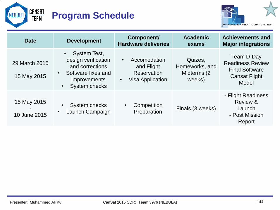
Team Logo
Here
(If You Want)
144
Program Schedule
CanSat 2015 CDR: Team 3976 (NEBULA)
Date DevelopmentComponent/
Hardware deliveries
Academic
exams
Achievements and
Major integrations
29 March 2015
-
15 May 2015
• System Test,
design verification
and corrections
• Software fixes and
improvements
• System checks
• Accomodation
and Flight
Reservation
• Visa Application
Quizes,
Homeworks, and
Midterms (2
weeks)
Team D-Day
Readiness Review
Final Software
Cansat Flight
Model
15 May 2015
-
10 June 2015
• System checks
• Launch Campaign
• Competition
PreparationFinals (3 weeks)
- Flight Readiness
Review &
Launch
- Post Mission
Report
Presenter: Muhammed Ali Kul

Team Logo
Here
(If You Want)
145
Program Schedule – Gantt Chart
CanSat 2015 CDR: Team 3976 (NEBULA)Presenter: Muhammed Ali Kul

Team Logo
Here
(If You Want) Shipping and Transportation
146CanSat 2015 CDR: Team 3976 (NEBULA)
• All the components will be transported inside safe containers.
• As we are ten members in our team, team will carry hardware part of
CanSat easily with safe boxes, then rent a car for transportation to the
launch site. To prevent critical part losses, the important components
and electronics will be carried inside hand baggages. (Necessary
permissions will be secured in advance)
– If our request is denied we will seek to ship our most critical parts via
a courier company with high safety levels
• For easier transport the antenna mast and the ground station will be
disassembled and manufactured using small parts.
• Tools will be transported with the CanSat, and we will be choose the
tools wisely, taking into account the possibility to loose them and being
ready to replace them in Texas.
• The CanSat and tools will be protected as needed. All parts of CanSat
will carry with safe boxes which resistant to damages.
Presenter: Muhammed Ali Kul

Team Logo
Here
(If You Want) Conclusions
147CanSat 2015 CDR: Team 3976 (NEBULA)
• Major accomplishments
– Team is established
– Preliminary Design is completed
– Critical Design is completed
– Manufacturing processes are decided
– Container and Payload prototypes are manufactured
• Major unfinished work
– Some system and subsystem tests are to be completed
• Additional work
– Sponsors for all kinds of expenses are to be found
• We hope that our design will be a success and we can make our
name to be heard.
Presenter: Muhammed Ali Kul