capacitors - search - university of maltastaff.um.edu.mt/pcam2/resources/capacitorz.pdf ·...
TRANSCRIPT

1
Capacitors
A capacitor is an electrical component that has the ability in storing charge.
Structurally a capacitor consists of two parallel metal plates, commonly made up of
Aluminium with an insulator in between referred to as dielectric, electrostatically
separating or isolating the two plates from each other.
The dielectric may be air, paper, wax paper, perspex or any other material with high
insulative properties.
The Capacitance of a capacitor
Capacitance may be considered as the measurement of the extent to which a capacitor can
store charge. It is its ability to store charge.
Metal Plate
Dielectric Metal Plate
Exploded View of Capacitor
Compact View of Capacitor
2
The capacitance is defined as the Charge on the plates of the capacitor per unit voltage
across the plates of the capacitor.
Units for Capacitance are faradays or farads in short symbol F.
Usually capacitance is denoted in terms of Microfaradays or Microfarads μF.
Incidentally 1 μF would be equivalent to 1X10 -6
F in S.I. denomination or units.
Physical Factors that influence the capacitance of a capacitor
The capacitance of the capacitor depends upon three major physical characteristics that
include:
a. The distance of plate
b. Area of overlap.
c. The permittivity of the dielectric
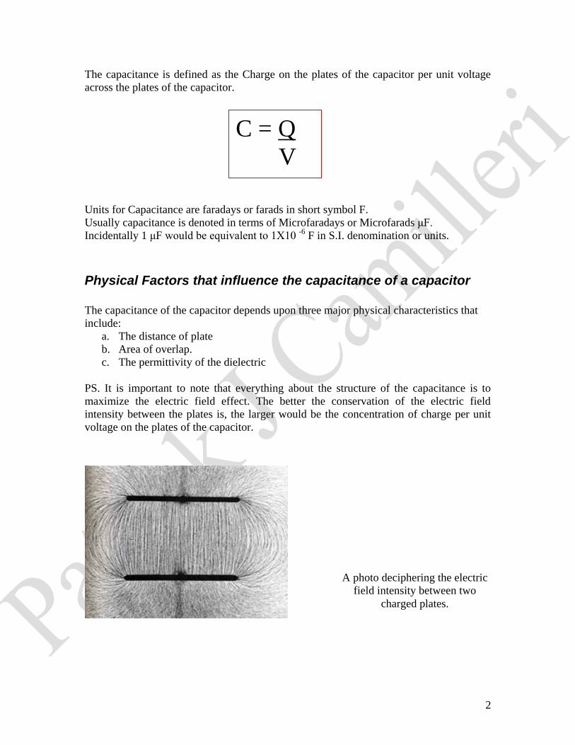
PS. It is important to note that everything about the structure of the capacitance is to
maximize the electric field effect. The better the conservation of the electric field
intensity between the plates is, the larger would be the concentration of charge per unit
voltage on the plates of the capacitor.
C = Q
V
A photo deciphering the electric
field intensity between two
charged plates.
3
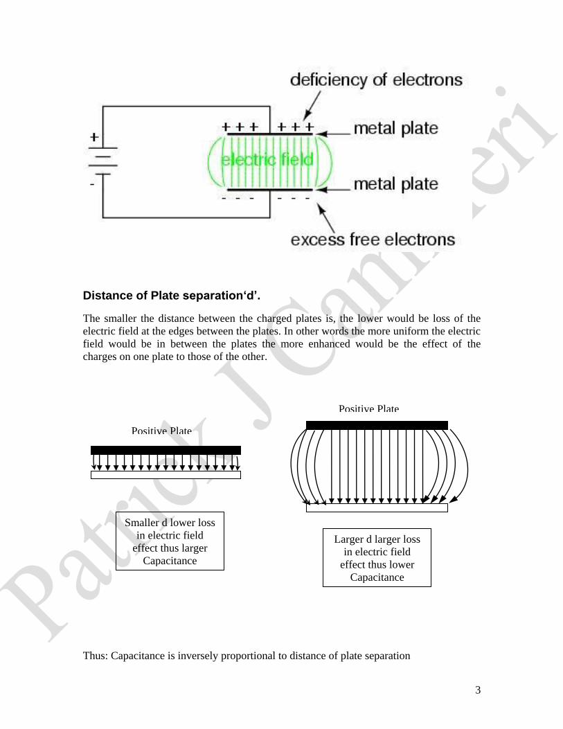
Distance of Plate separation‘d’.
The smaller the distance between the charged plates is, the lower would be loss of the
electric field at the edges between the plates. In other words the more uniform the electric
field would be in between the plates the more enhanced would be the effect of the
charges on one plate to those of the other.
Thus: Capacitance is inversely proportional to distance of plate separation
Smaller d lower loss
in electric field
effect thus larger
Capacitance
Larger d larger loss
in electric field
effect thus lower
Capacitance
Positive Plate
Positive Plate
4
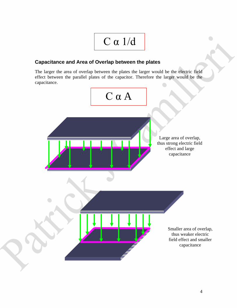
Capacitance and Area of Overlap between the plates
The larger the area of overlap between the plates the larger would be the electric field
effect between the parallel plates of the capacitor. Therefore the larger would be the
capacitance.
Large area of overlap,
thus strong electric field
effect and large
capacitance
Smaller area of overlap,
thus weaker electric
field effect and smaller
capacitance
C α A
C α 1/d
5
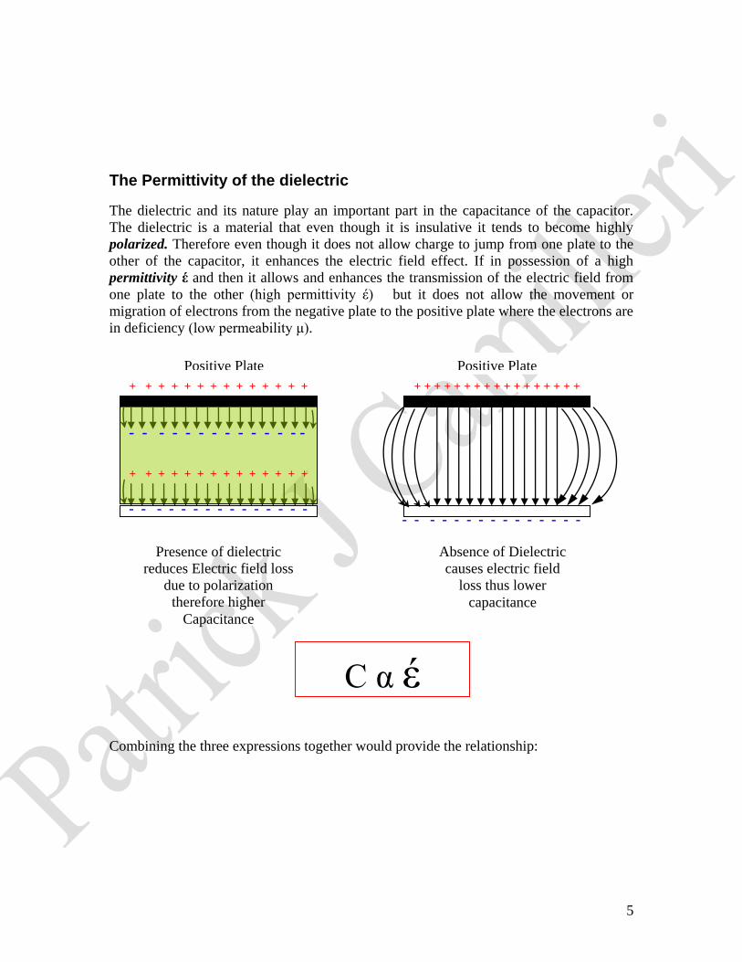
The Permittivity of the dielectric
The dielectric and its nature play an important part in the capacitance of the capacitor.
The dielectric is a material that even though it is insulative it tends to become highly
polarized. Therefore even though it does not allow charge to jump from one plate to the
other of the capacitor, it enhances the electric field effect. If in possession of a high
permittivity έ and then it allows and enhances the transmission of the electric field from
one plate to the other (high permittivity έ) but it does not allow the movement or
migration of electrons from the negative plate to the positive plate where the electrons are
in deficiency (low permeability μ).
Combining the three expressions together would provide the relationship:
Presence of dielectric
reduces Electric field loss
due to polarization
therefore higher
Capacitance
Absence of Dielectric
causes electric field
loss thus lower
capacitance
Positive Plate
+ + + + + + + + + + + + + + + + +
+ ++++++ + + + + + + + + + + + + + +
+ + + ++++++
+ + + + + + + + + + + + + +
+ + + ++++++
- - - - - - - - - - - - - -
- - - -
- - - - - - - - - - - - - - - - - - - - - - - - - - - - - -
Positive Plate
C α έ
6
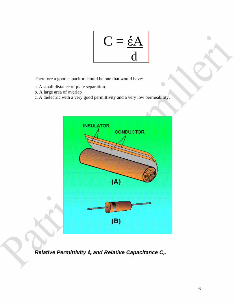
Therefore a good capacitor should be one that would have:
a. A small distance of plate separation.
b. A large area of overlap
c. A dielectric with a very good permittivity and a very low permeability.
Relative Permittivity έr and Relative Capacitance Cr.
C = έA d

7
The relative permittivity is the ratio of the permittivity of a dielectric to that of air.
(Incidentally unless otherwise stated the permittivity of air is taken to be equivalent to
that of vacuum and is referred as the permittivity of free space έ0 )
Thus
Relative Permittivity of a material = Permittivity of named Material
Permittivity of free space
έ r = έ material
έ 0
If the capacitance C of a capacitor = έA
d
Then using a capacitor with air as a dielectric would give C0 = έ0A d …….(i)
Where C0 is the capacitance of a capacitor using air as a dielectric and έ0 is the
permittivity of free space
If the capacitor makes use of another dielectric for instance by replacing air with Perspex
then CP = έPA d …….(ii)
Where CP is the capacitance of a capacitor using air as a dielectric and έP is the
permittivity of Perspex.
Dividing equation (ii) by equation (i): CR = CP =
Thus the relative capacitance CR = CP = έP = έR
έ0
Types of Capacitors
Capacitors are used in electric circuits for various purposes. Different types of capacitors
make use of different types of dielectrics. The choice of the dielectric usually depends on
έ0A
d
C0
έPA
d
d
C0

8
the value of the capacitance and the stability required for the capacitor that is the way its
capacitance will vary as it ages.
For every dielectric there is a specific potential gradient or a maximum potential above
which the capacitance of the capacitor will break down. The breaking potential usually
depends upon the permittivity and the thickness of the dielectric. Liquid and gaseous
capacitors usually recover their original properties whenever the applied Pd is reduced
below the breaking voltage, but this is not the case with many solid dielectrics.
a. Paper, plastic, ceramic and mica capacitors
Uniform layers of waxed paper, plastics (like polystyrene), ceramics (like talc with
barium titanate) and mica are all used for as dielectrics. Capacitance for these types of
capacitors rarely exceeds a few microfarads and in the case of mica the upper limit is
about 0.01μF.
b. Electrolytic Capacitors
These have capacitances up to 10000 μF and are quiet compact because they employ very
thin layers of dielectrics typically in the region of 10-3
mm and can withstand very high
voltages without breaking down. The problem with electrolytic capacitors is that they
have dedicated terminals and reversing the connections of an electrolytic capacitor would
cause it breakdown beyond repair.
The film applied would usually involve a thin aluminium oxide film formed by passing a
small current through a paper soaked with an aluminium borate solution separating two
aluminium electrodes. The oxide forming on one of the electrodes would act as one of the
plates of the capacitor.
9
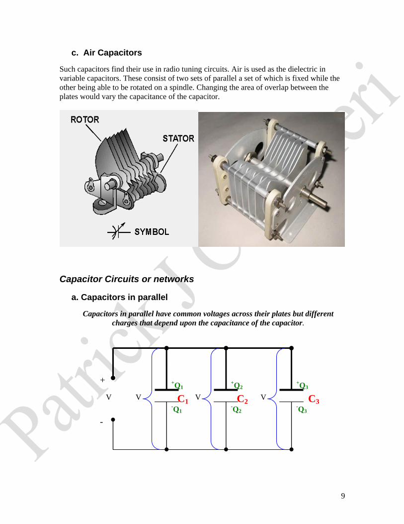
c. Air Capacitors
Such capacitors find their use in radio tuning circuits. Air is used as the dielectric in
variable capacitors. These consist of two sets of parallel a set of which is fixed while the
other being able to be rotated on a spindle. Changing the area of overlap between the
plates would vary the capacitance of the capacitor.
Capacitor Circuits or networks
a. Capacitors in parallel
Capacitors in parallel have common voltages across their plates but different
charges that depend upon the capacitance of the capacitor.
+
-
V V V V C1 C2 C3
+Q1
+Q2
+Q3
-Q1
-Q2
-Q3
10
Thus: Q1 = C1V, Q2 = C1V, Q3 = C3V
If total charge Q = Q1 + Q2 + Q3
Then Q = V (C1+C2+C3)
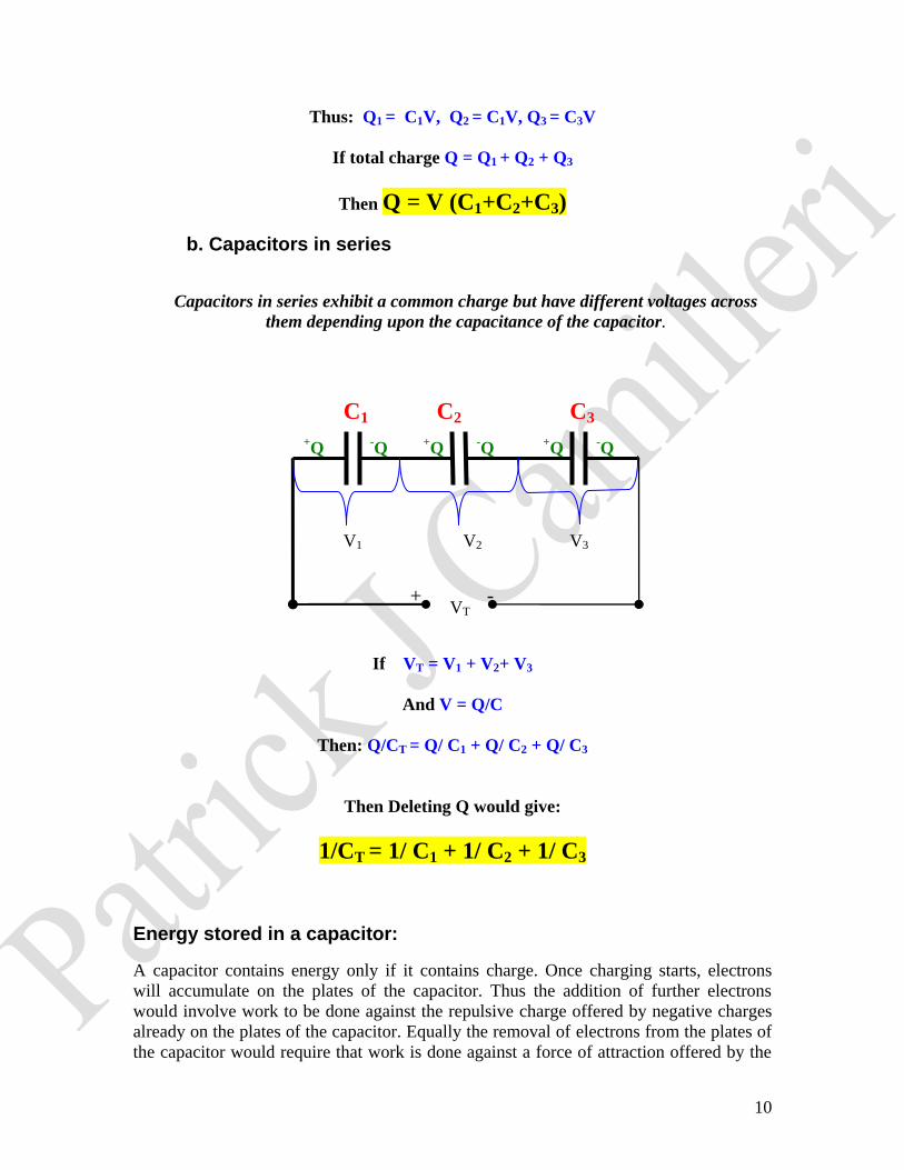
b. Capacitors in series
Capacitors in series exhibit a common charge but have different voltages across
them depending upon the capacitance of the capacitor.
If VT = V1 + V2+ V3
And V = Q/C
Then: Q/CT = Q/ C1 + Q/ C2 + Q/ C3
Then Deleting Q would give:
1/CT = 1/ C1 + 1/ C2 + 1/ C3
Energy stored in a capacitor:
A capacitor contains energy only if it contains charge. Once charging starts, electrons
will accumulate on the plates of the capacitor. Thus the addition of further electrons
would involve work to be done against the repulsive charge offered by negative charges
already on the plates of the capacitor. Equally the removal of electrons from the plates of
the capacitor would require that work is done against a force of attraction offered by the
+ _- VT
V2
C1 C2 C3
+Q
+Q
+Q
-Q
-Q
-Q
V1 V3
11
positive charges present on the plates of the capacitor the work which done is stored as
electrical potential energy on the plates of the capacitor.
Let the energy stored on the plates of the capacitor = W Units Joules J
Let the capacitance of the capacitor = C Units farads F
Let the pd across the plates of the capacitor = V Units Volts V
Let the charge on the plates of the capacitor = Q Units Coulombs C
Thus Energy stored on the plates of the capacitor is :
W= Q2/2C = ½ (CV2) = ½ (QV)
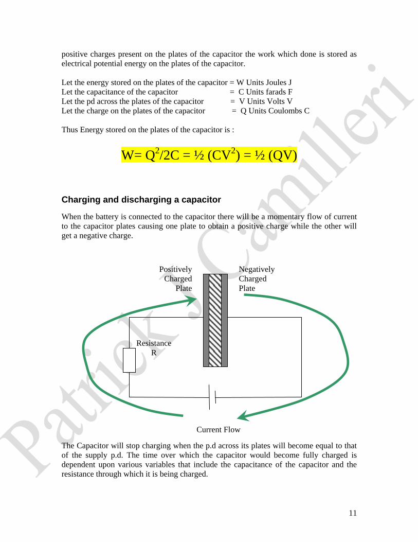
Charging and discharging a capacitor
When the battery is connected to the capacitor there will be a momentary flow of current
to the capacitor plates causing one plate to obtain a positive charge while the other will
get a negative charge.
The Capacitor will stop charging when the p.d across its plates will become equal to that
of the supply p.d. The time over which the capacitor would become fully charged is
dependent upon various variables that include the capacitance of the capacitor and the
resistance through which it is being charged.
Positively
Charged
Plate
Negatively
Charged
Plate
Current Flow
Resistance
R
12
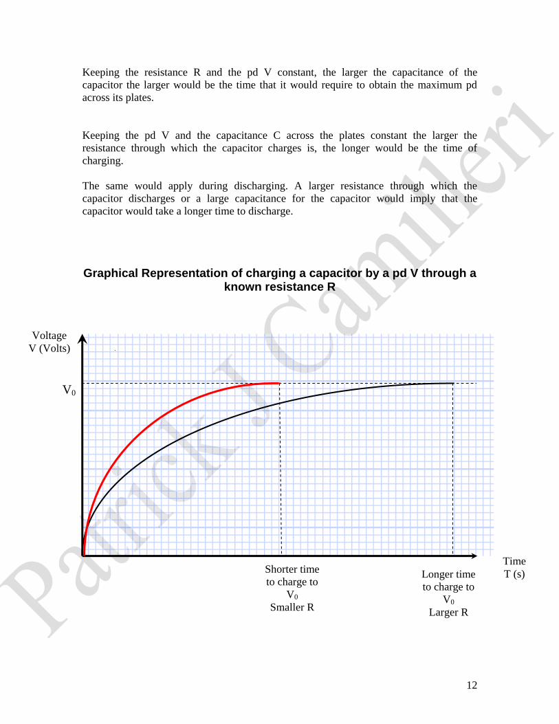
Keeping the resistance R and the pd V constant, the larger the capacitance of the
capacitor the larger would be the time that it would require to obtain the maximum pd
across its plates.
Keeping the pd V and the capacitance C across the plates constant the larger the
resistance through which the capacitor charges is, the longer would be the time of
charging.
The same would apply during discharging. A larger resistance through which the
capacitor discharges or a large capacitance for the capacitor would imply that the
capacitor would take a longer time to discharge.
Graphical Representation of charging a capacitor by a pd V through a known resistance R
Shorter time
to charge to
V0
Smaller R
Voltage
V (Volts)
Time
T (s)
V0
Longer time
to charge to
V0
Larger R
13
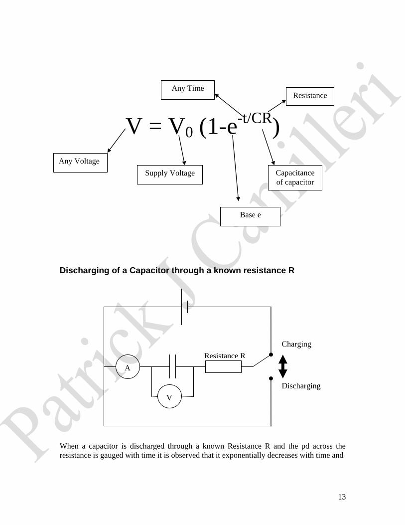
V = V0 (1-e-t/CR
)
Discharging of a Capacitor through a known resistance R
When a capacitor is discharged through a known Resistance R and the pd across the
resistance is gauged with time it is observed that it exponentially decreases with time and
V
Charging
Discharging
Resistance R
A
Any Voltage
Supply Voltage Capacitance
of capacitor
Resistance Any Time
Base e
14
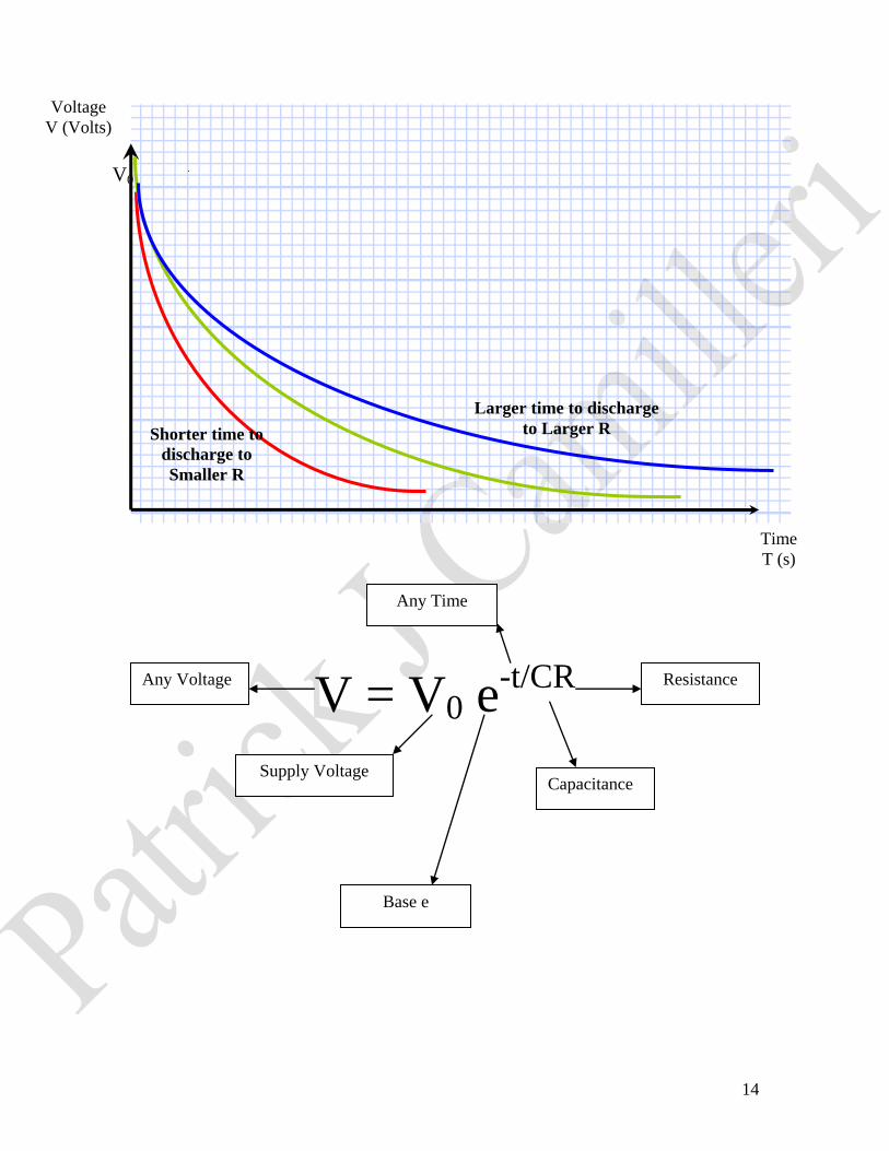
V = V0 e-t/CR
Larger time to discharge
to Larger R Shorter time to
discharge to Smaller R
V0
Time
T (s)
Voltage
V (Volts)
Any Voltage
Supply Voltage
Any Time
Capacitance
Resistance
Base e

15
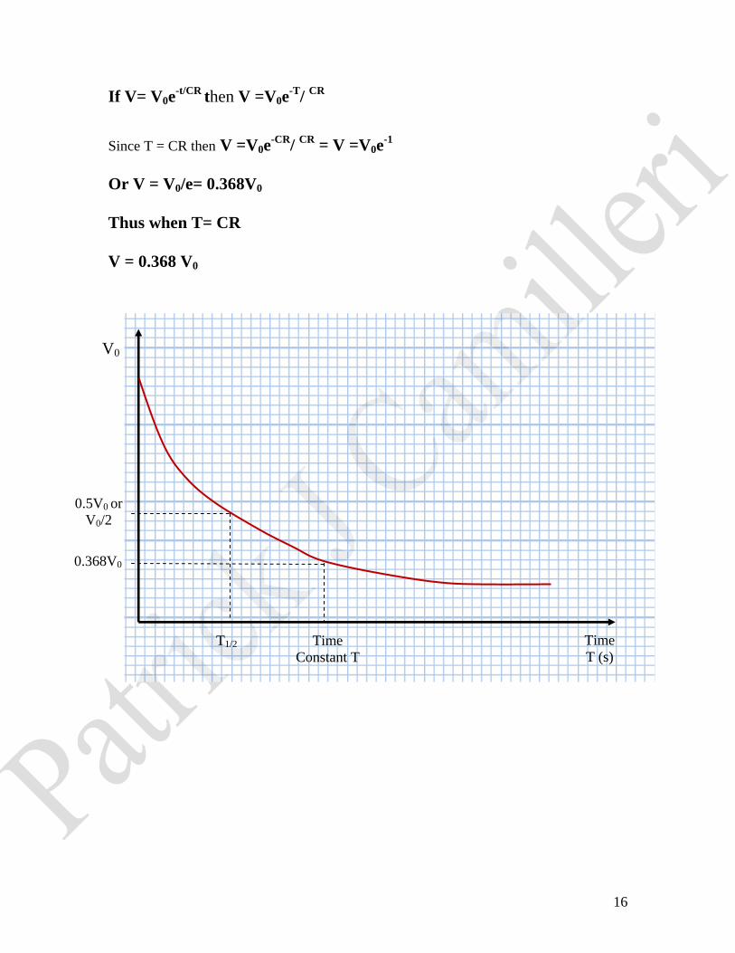
Important times for charging and discharging include the half life T1/2 and the time
constant T.
The Half Life time T1/2 is the time required for the pd across or charge on the plates of
the capacitor to:
1. Decrease by half during discharging.
2. Increase by half during charging.
Time constant T which is equal to CR is equivalent for the pd across the plates of the
capacitor or the charge on the plates of the capacitor to:
1. Decrease to approximately 38% during discharging
2. Increase to approximately 63% during charging.
The Half Life Time and discharging:
During discharge the half life time T1/2 would be equivalent for the pd V0 to decrease to
V0/2.
Thus if for discharging V= V0e-t/CR
Then: V0/2 =V0e-T
1/2/ CR
Thus: ½ = e-T
1/2/CR
2= e T
1/2/CR
(Removal of negative sign will reduce ½ to 2)
ln 2 = T1/2/CR
0.6931= T1/2/CR
0.6931CR= T1/2
The Time Constant T and discharging:
When any time t is equal to the time constant T, then
16
If V= V0e-t/CR
then V =V0e-T
/ CR
Since T = CR then V =V0e-CR
/ CR
= V =V0e-1
Or V = V0/e= 0.368V0
Thus when T= CR
V = 0.368 V0
Time
T (s)
V0
0.368V0
0.5V0 or
V0/2
T1/2 Time
Constant T