high voltage solid polymer tantalum capacitors - t521
TRANSCRIPT

©2010 Electronic Components Association, Inc., Arlington, Virginia, USA
CARTS 2010 Conference Proceedings, CARTS 2010 Conference, New Orleans, LA, USA, April 2010 Page 1 of 13
Performance and Reliability Study of High Voltage Tantalum Polymer Capacitors
Jayson Young, Jake Qiu, Randy Hahn
Kemet Electronics PO Box 5928 Greenville, SC 29606
864-963-6300 Phone
Introduction
The need for reliable components with smaller form factors continues to drive many of the innovation efforts within the passive components community. For applications requiring the smallest component options available, tantalum chip capacitors remain the best option for capacitance values that exceed the reaches of MLCC capacitors. Today, the best options for higher capacitance needs are being met by both MnO2 and polymer tantalum chip capacitors as well as surface mount aluminum electrolytic capacitors. As with all component technologies, each has its own set of strengths and weaknesses that designers must take into account when making their component selections. Among these are the capacitance range, voltage range, impedance characteristics, reliability, and physical size. This paper will focus specifically on the advancements recently made in polymer tantalum chip capacitors using the latest breakthrough technologies in polymer cathode systems. We will assess the long term reliability of these new devices, assess the surge handling capabilities of the components, consider the capacitance options that are becoming available and finally assess their size advantage compared to other capacitor options.
Tantalum Polymer Capacitors Overcome ESR and Voltage Limitations In the late 1990’s, the tantalum chip capacitor underwent a major innovation milestone when the semi-conductive solid state cathode material, MnO2, was replaced with an intrinsically conductive polymer cathode system. The introduction of this new material set drastically reduced the parasitic Equivalent Series Resistance (ESR) within the tantalum chip capacitor by eliminating the most resistive component of the capacitor, the MnO2 cathode. This innovation has been well documented over the past ten years1, proving the ESR advantages and benign failure mode that polymer cathode systems offer over MnO2. While this innovation addressed the two critical needs for improved ESR and the removal of an undesirable failure mode within tantalum capacitors, the advancement was limited in its voltage reach and by early 2003 the industry stalled out on voltage extensions and could not extend the use of polymer cathode systems beyond 25V rated devices that were recommended for 20V or lower applications. This left the need for higher voltage ratings and long term reliability at higher voltages unanswered for many years. Finally, in 2008, industry leaders announced the development of the first 35V polymer tantalum chip capacitors2, designated as the T521 Series by Kemet Electronics Corp. This advancement was achieved through the use of an alternative polymerization process that delivered a robust dielectric that could withstand steady state voltage stresses beyond 28V. This breakthrough in polymer technology now meant that polymer tantalum chip capacitors could cover the full reach of traditional MnO2 tantalum chip capacitors in terms of voltage and capacitance offerings and do so while delivering much improved ESR with no risk of ignition failures. With tantalum polymer chip capacitors now extending to 28V applications and two years of further research completed, a greater understanding of the performance advantages of this latest advancement has been gained. The most value added advantages to the user community are discussed below.
Long Term Reliability of High Voltage Polymer Capacitors To assess the reliability of polymer capacitors built with the new polymerization process, a series of long term life tests have been conducted under various voltage conditions. In assessing the long term performance and reliability of tantalum polymer capacitors, dielectric performance over time must be assessed. To assess dielectric performance, the
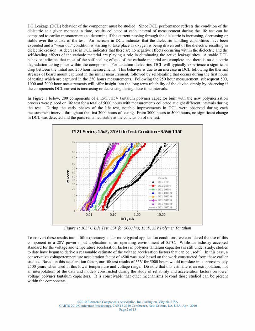
DC Leakage (DCL) behavior of the component must be studied. Since DCL performance reflects the condition of the dielectric at a given moment in time, results collected at each interval of measurement during the life test can be compared to earlier measurements to determine if the current passing through the dielectric is increasing, decreasing or stable over the course of the test. An increase in DCL indicates that the dielectric handling capabilities have been exceeded and a “wear out” condition is starting to take place as oxygen is being driven out of the dielectric resulting in dielectric erosion. A decrease in DCL indicates that there are no negative effects occurring within the dielectric and the self-healing effects of the cathode material are playing a role in eliminating the active leakage sites. A stable DCL behavior indicates that most of the self-healing effects of the cathode material are complete and there is no dielectric degradation taking place within the component. For tantalum dielectrics, DCL will typically experience a significant drop between the initial and 250 hour measurements. This behavior is due to an increase in DCL following the thermal stresses of board mount captured in the initial measurement, followed by self-healing that occurs during the first hours of testing which are captured in the 250 hours measurements. Following the 250 hour measurement, subsequent 500, 1000 and 2000 hour measurements will offer insight into the long term reliability of the device simply by observing if the components DCL current is increasing or decreasing during these time intervals. In Figure 1 below, 200 components of a 15uF, 35V tantalum polymer capacitor built with the new polymerization process were placed on life test for a total of 5000 hours with measurements collected at eight different intervals during the test. During the early phases of the life test, notable improvements in DCL were observed during each measurement interval throughout the first 3000 hours of testing. From 3000 hours to 5000 hours, no significant change in DCL was detected and the parts remained stable at the conclusion of the test.
Figure 1: 105° C Life Test, 35V for 5000 hrs; 15uF, 35V Polymer Tantalum
To convert these results into a life expectancy under more typical application conditions, we considered the use of this component in a 28V power input application in an operating environment of 85°C. While an industry accepted standard for the voltage and temperature acceleration factors in polymer tantalum capacitors is still under study, studies to date have begun to derive a reasonable estimate of the voltage acceleration factors that can be used3,4. In this case, a conservative voltage/temperature acceleration factor of 4500 was used based on the work constructed from these earlier studies. Based on this acceleration factor, our life test results of 35V for 5000 hours would translate into approximately 2500 years when used at this lower temperature and voltage range. Do note that this estimate is an extrapolation, not an interpolation, of the data and models constructed during the study of reliability and acceleration factors on lower voltage polymer tantalum capacitors. It is conceivable that other mechanisms beyond those studied can be present within the components.
©2010 Electronic Components Association, Inc., Arlington, Virginia, USA
CARTS 2010 Conference Proceedings, CARTS 2010 Conference, New Orleans, LA, USA, April 2010 Page 2 of 13

While the outcome of the above life test concluded that the components would outlast the life time needs of the hardware they are placed in, determining the life expectancy of the design was not achieved during this test. An acceleration condition was needed to generate failures at a much more rapid rate.
Acceleration Studies of High Voltage Polymer Capacitors To begin assessing the maximum accelerated stress levels the components could withstand, a new set of life tests were initiated using a voltage stress level of 50V for the same 35V part types studied above (1.43 x Rated Voltage). For MnO2 tantalum capacitors, this accelerated voltage condition would reflect an acceleration factor of 3200; meaning that 1 hour of testing at 50V is equivalent to 3200 hours at 35V. A test population of 100 components was used for this analysis. At the time this paper was prepared, testing through 2000 hours had been completed with testing still underway to collect further measurements at 3,000 to 5,000 hours. The objective of this test was to generate a sufficient number of failures to construct a failure rate plot under an accelerated condition. However, at the 2000 hour measurement interval, only 7% of the population had failed. Given the limited number of failures, no conclusions could be derived at the 2000 hour interval. Since failures were just starting to be generated, further failures needed to be generated to plot the failure rate over time. While more data is needed, information collected to date has shown that even at an accelerated voltage of 1.43Vr @ 105°C for 2000 hours, components manufactured with this new polymer process will require greater stress levels than initially predicted in order to generate failures in a more reasonable period of time.
Figure 2: Accumulative Failures of 35V Polymer Tantalum on 50V Life Test
During this life test, DCL performance demonstrated continuous improvement during the 250 and 500 hour measurement intervals (See Figure 3). However, at 1000 hours a decline in DCL performance was detected indicating that the voltage stresses were beginning to impact the dielectric to some degree. A further decline in DCL performance was noted at the 2000 hour measurement interval indicating that the acceleration condition had at least entered the early stages of dielectric degradation.
©2010 Electronic Components Association, Inc., Arlington, Virginia, USA
CARTS 2010 Conference Proceedings, CARTS 2010 Conference, New Orleans, LA, USA, April 2010 Page 3 of 13

Figure 3: 105° C Life Test for 2000 hrs @ 50V; 15uF, 35V Polymer Tantalum (7 failures removed)
While 7% of the population experienced dielectric failure from the 50V stresses during the first 2000 hours, attention was placed on the outcome of the remaining 93% of the test population. Referring back to Figure 3, it should be noted that of the components remaining active at the end of the 2000 hour test, every component maintained a DCL value of less than 1.5uA. To understand the significance of this outcome, we compared these results to the behavior of the MnO2 tantalum capacitor which typically defines a catalog DCL value that is 1/10th that of polymer tantalum capacitors. Since MnO2 tantalum capacitors are not categorized as having a 105°C rated temperature, life test data from this temperature range was not readily available for an immediate comparison. Instead, a review of 85°C life tests history was used from a 15uF, 50V rated tantalum capacitor. While the test temperature from the MnO2 Life test was lower, the voltage stress was identical to that applied to the 35V polymer tantalum part placed on the 50V life test. In addition, the MnO2 data collected for comparison was from a larger case size (7343-43). Given the disadvantages of a thinner dielectric, higher test temperature, polymer cathode and a smaller case size, the polymer tantalum capacitors DCL values were expected to be higher than that of the MnO2. However, as shown in Figure 4, the DCL performance of approximately 40% of the MnO2 devices was comparable to the polymer devices while the remaining 60% of the MnO2 devices demonstrated a DCL value that was higher than the polymer devices. These results brought to light a new advantage for polymer tantalum capacitors built with this new process since polymer tantalum capacitors built with the established polymer processes typically maintain a higher DCL value than MnO2, thus making them less desirable for certain power supplies such as those that are battery dependent. Based on the results gathered during this comparison, the advantages of MnO2 over polymer devices in terms of DCL performance could no longer be assumed.
©2010 Electronic Components Association, Inc., Arlington, Virginia, USA
CARTS 2010 Conference Proceedings, CARTS 2010 Conference, New Orleans, LA, USA, April 2010 Page 4 of 13

Figure 4: Life Test DC Leakage Performance @ 2000 Hrs, 35V Polymer Tantalum verses 50V Mn02 Tantalum
Extending Polymer Tantalum Capacitors beyond 35V While work continues on establishing a more exact reliability model, experiments have been conducted on the use of this new process with higher voltage rated devices. During the initial experiment, polymer tantalum components were built with a true 50V dielectric construction to determine if the devices could be reliably built to voltage ratings greater that the 35V ratings recently achieved. This experiment included a 15uF component design for the 50V rated device built in the 7343-20 case size. These 50V devices were placed on the same 50V Life Test as above with an applied voltage of 50V and test temperature of 105° C. At the time this paper was being prepared, the life test had completed 2000 hours of testing. As shown in Figure 5, the DC Leakage performance of product built with a 50V dielectric continued to demonstrate stable DC Leakage performance with no degradation through 2000 hours of testing. After 2000 hours, no short circuit failures had occurred. However, an increase in DC Leakage was starting to appear with 6% of the population experiencing a more noticeable increase in DCL.
Figure 5: 50V Design DC Leakage (0, 250, 500, 1000, 2000 hrs)
©2010 Electronic Components Association, Inc., Arlington, Virginia, USA
CARTS 2010 Conference Proceedings, CARTS 2010 Conference, New Orleans, LA, USA, April 2010 Page 5 of 13

While DCL was beginning to show evidence of an increase, the population continued to demonstrate DCL values that were comparable to the lower DCL behaviors of MnO2 tantalum capacitors. Figure 6 below summarizes a comparison of the 15uF, 50V polymer tantalum life test above to the results of the life test presented on a 15uF, 50V MnO2 tantalum capacitor. Unlike the early comparison of the 35V polymer tantalum device, this comparison does eliminate the variation in dielectric construction and assesses parts built with the same dielectric condition. The same variations as above in test temperature, cathode material and case size remained constant. As with the earlier comparison, the polymer tantalum capacitors actually delivered a lower DCL value on average than the traditional MnO2 designs. While not captured in the plot, it can also be noted that the improved DCL performance was evident early on in the life test with the polymer tantalum capacitors maintaining a lower average DCL value at 250 hrs as compared to the MnO2 at this same time interval.
Figure 6: Life Test DC Leakage Performance @ 2000 Hrs, 50V Polymer Tantalum verses 50V Mn02 Tantalum
Since this design was the first 50V polymer tantalum device to be constructed, the ESR stability of the 50V design also needed to be explored. As shown in Figure 7 below, the design demonstrated typical ESR behavior with an initial increase in ESR detected between the initial and 250 hour measurement and no significant ESR movement observed beyond the 250 hour measurement. This behavior was considered to be typical for polymer tantalum capacitors with no unusual behaviors detected.
©2010 Electronic Components Association, Inc., Arlington, Virginia, USA
CARTS 2010 Conference Proceedings, CARTS 2010 Conference, New Orleans, LA, USA, April 2010 Page 6 of 13

Figure 7: Polymer Tantalum 50V Design ESR (0, 250, 500, 1000, 2000hrs)
The results of this initial 50V design analysis demonstrate that voltage ratings beyond 35V ratings are achievable in tantalum polymer construction. In addition, these higher voltage ratings have the potential to prove themselves more reliable than the currently used 50V MnO2 tantalum chip capacitor solutions.
Surge Handling Capabilities While the above studies have demonstrated that higher voltage tantalum polymer chip capacitors provide good long term reliability at maximum rated steady state conditions, concerns with voltage transients on power input circuits are often of greater concern. Since input power rails such as 24V and 28V inputs can experience transients of as much as 5V or more, design engineers must ensure that the selected capacitor performs well under the most extreme transient conditions. To assess the transient or surge handling capabilities of these components, a Step Surge Stress Test (SSST) was conducted to determine the Breakdown Voltage (BDV) of these new devices as compared to traditional MnO2 devices. The 35V tantalum polymer capacitors as well as a series of traditional 50V MnO2 tantalum capacitors from three different manufacturers were selected for this test. These components were selected based on their common use in 24V and 28V power rails. The objective of the SSST is to apply increasing voltage stress levels through a low impedance circuit and drive components to failure. Failures are recorded on a probability plot in order to provide a prediction on the fallout rate of the population at a given voltage. The probability plot provided below in Figure 8 summarizes the results of this test using the 15uF, 35V polymer tantalum capacitor. A total test population of 1200 components was tested. During testing, 100% of the test population withstood surge conditions beyond 50V. From 56V to 65V, the weakest components from the test lot began to fallout. As the test approached 70V, more than 98% of the test population was still withstanding these voltage stresses.
©2010 Electronic Components Association, Inc., Arlington, Virginia, USA
CARTS 2010 Conference Proceedings, CARTS 2010 Conference, New Orleans, LA, USA, April 2010 Page 7 of 13

Applying these results to a 24V or even 28V application, the predicted fallout rate at these application voltages was at zero parts per million (PPM). This test was repeated multiple times with multiple manufacturing lots. The results of these tests show little to no variation in performance.
Figure 8: BDV behavior of a 15uF, 35V polymer tantalum
The 50V MnO2 tantalum components were subjected to the same test procedure. Summarized in Figures 9-11, the results concluded that one of the three 50V test groups was comparable to the 35V polymer capacitor in terms of the probability plot and predicted PPM rates at 24V to 28V. However, the remaining two groups were found to be less robust than the polymer product. With regard to initial failures, Manufacturer A did not experience failures until 56V, Manufacturer B experienced failures starting at 24V and Manufacturer C began to experience failures at 35V. When assessed for a 24V application, the predicted fallout rate for each of the groups was: Manufacturer A = 1 PPM, Manufacturer B = 753PPM, Manufacturer C = 3200PPM. The results of this SSST analysis demonstrate the 35V polymer tantalum’s surge robustness verses a traditional 50V MnO2 tantalum capacitor. The lower voltage rated polymer tantalum device offers, at a minimum, comparable surge handling capability to Manufacturer A’s 50V MnO2 tantalum devices and would be superior to that of Manufacturer B and C’s 50V MnO2 devices. In addition, it should be noted that the 35V polymer device was constructed within a 7343-20 case dimension while the 3 groups of 50V MnO2 devices were constructed in 7343-43 designs. While longer case sizes often allow for improved electrical perform due to their larger size and more robust construction, the advantage of case size did not outweigh the advantages of the new polymer cathode process.
©2010 Electronic Components Association, Inc., Arlington, Virginia, USA
CARTS 2010 Conference Proceedings, CARTS 2010 Conference, New Orleans, LA, USA, April 2010 Page 8 of 13

Figure 9: BDV behavior of a 10uF, 50V MnO2 Tantalum: Manufacturer A
Figure 10: BDV behavior of a 10uF, 50V MnO2 Tantalum: Manufacturer B
©2010 Electronic Components Association, Inc., Arlington, Virginia, USA
CARTS 2010 Conference Proceedings, CARTS 2010 Conference, New Orleans, LA, USA, April 2010 Page 9 of 13

Figure 11: BDV behavior of a 10uF, 50V MnO2 Tantalum: Manufacturer C
Ripple Current Handling An improvement in the ESR performance of polymer tantalum capacitors as compared to MnO2 tantalum capacitors is well understood in the industry. But ESR's role in improving ripple current is perhaps of greater interest to designers working with higher voltage power rails. For tantalum capacitors, the maximum allowable ripple current rating of the device is a function of the ESR rating of the device and its power dissipation capability. Power dissipation capability is a function of capacitor case size with larger case sizes allowing for higher power dissipation. Lower ESR ratings and/or higher dissipation ratings allow for higher maximum ripple current ratings. To offer a comparison of the ripple current handling capabilities of these higher voltage polymer tantalum capacitors verses the MnO2 tantalum capacitor, two values from each technology were selected based on a given voltage and capacitance need for two specific applications. In each instance, the case size of the polymer tantalum capacitor selected was smaller than the MnO2 device selected for the same application. However, in both instances, the maximum ripple allowance of the polymer tantalum device exceeded that of the MnO2 device given the lower ESR ratings of the polymer tantalum devices which outweighed the advantage of the larger case sizes of the MnO2 tantalum devices.
Table 1: Comparison of Maximum Ripple Current Limits: Polymer Tantalum verses MnO2 Tantalum
©2010 Electronic Components Association, Inc., Arlington, Virginia, USA CARTS 2010 Conference Proceedings, CARTS 2010 Conference, New Orleans, LA, USA, April 2010
Page 10 of 13
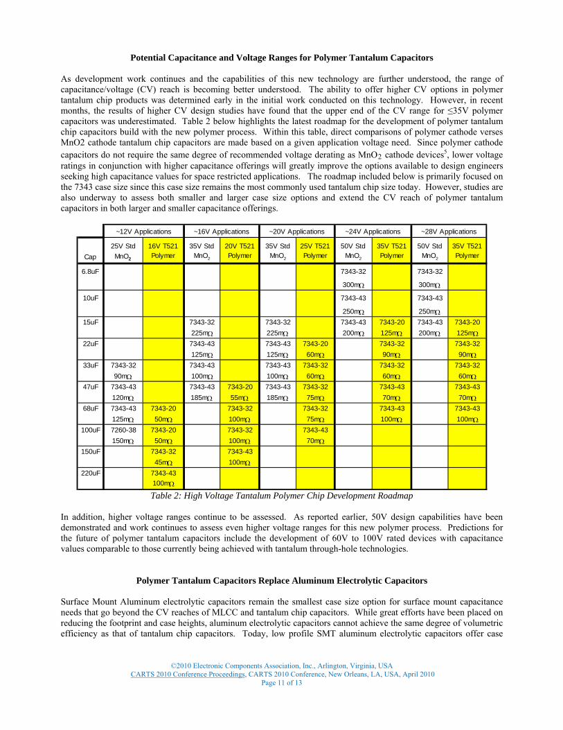
Potential Capacitance and Voltage Ranges for Polymer Tantalum Capacitors As development work continues and the capabilities of this new technology are further understood, the range of capacitance/voltage (CV) reach is becoming better understood. The ability to offer higher CV options in polymer tantalum chip products was determined early in the initial work conducted on this technology. However, in recent months, the results of higher CV design studies have found that the upper end of the CV range for ≤35V polymer capacitors was underestimated. Table 2 below highlights the latest roadmap for the development of polymer tantalum chip capacitors build with the new polymer process. Within this table, direct comparisons of polymer cathode verses MnO2 cathode tantalum chip capacitors are made based on a given application voltage need. Since polymer cathode capacitors do not require the same degree of recommended voltage derating as MnO2 cathode devices5, lower voltage ratings in conjunction with higher capacitance offerings will greatly improve the options available to design engineers seeking high capacitance values for space restricted applications. The roadmap included below is primarily focused on the 7343 case size since this case size remains the most commonly used tantalum chip size today. However, studies are also underway to assess both smaller and larger case size options and extend the CV reach of polymer tantalum capacitors in both larger and smaller capacitance offerings.
~24V Applications
Cap25V Std MnO2
16V T521 Polymer
35V Std MnO2
20V T521 Polymer
35V Std MnO2
25V T521 Polymer
50V Std MnO2
35V T521 Polymer
50V Std MnO2
35V T521 Polymer
6.8uF 7343-32 7343-32
300mΩ 300mΩ
10uF 7343-43 7343-43
250mΩ 250mΩ15uF 7343-32 7343-32 7343-43 7343-20 7343-43 7343-20
225mΩ 225mΩ 200mΩ 125mΩ 200mΩ 125mΩ22uF 7343-43 7343-43 7343-20 7343-32 7343-32
125mΩ 125mΩ 60mΩ 90mΩ 90mΩ33uF 7343-32 7343-43 7343-43 7343-32 7343-32 7343-32
90mΩ 100mΩ 100mΩ 60mΩ 60mΩ 60mΩ47uF 7343-43 7343-43 7343-20 7343-43 7343-32 7343-43 7343-43
120mΩ 185mΩ 55mΩ 185mΩ 75mΩ 70mΩ 70mΩ68uF 7343-43 7343-20 7343-32 7343-32 7343-43 7343-43
125mΩ 50mΩ 100mΩ 75mΩ 100mΩ 100mΩ100uF 7260-38 7343-20 7343-32 7343-43
150mΩ 50mΩ 100mΩ 70mΩ150uF 7343-32 7343-43
45mΩ 100mΩ220uF 7343-43
100mΩ
~12V Applications ~16V Applications ~20V Applications ~28V Applications
Table 2: High Voltage Tantalum Polymer Chip Development Roadmap
In addition, higher voltage ranges continue to be assessed. As reported earlier, 50V design capabilities have been demonstrated and work continues to assess even higher voltage ranges for this new polymer process. Predictions for the future of polymer tantalum capacitors include the development of 60V to 100V rated devices with capacitance values comparable to those currently being achieved with tantalum through-hole technologies.
Polymer Tantalum Capacitors Replace Aluminum Electrolytic Capacitors Surface Mount Aluminum electrolytic capacitors remain the smallest case size option for surface mount capacitance needs that go beyond the CV reaches of MLCC and tantalum chip capacitors. While great efforts have been placed on reducing the footprint and case heights, aluminum electrolytic capacitors cannot achieve the same degree of volumetric efficiency as that of tantalum chip capacitors. Today, low profile SMT aluminum electrolytic capacitors offer case
©2010 Electronic Components Association, Inc., Arlington, Virginia, USA
CARTS 2010 Conference Proceedings, CARTS 2010 Conference, New Orleans, LA, USA, April 2010 Page 11 of 13

heights of between 5.0mm to 10.0mm depending on the capacitance and voltage needs. Polymer tantalum capacitors are available in case heights ranging from 2.0mm to 4.3mm with smaller case sizes currently under development. As shown in the development roadmap above, the advancement of higher voltage polymer tantalum capacitors has begun to extend the polymer tantalum capacitor reach into CV values that were previously only available in surface mountable aluminum electrolytic offerings. Many of the T521 Series releases have been put into immediate use as an aluminum electrolytic capacitor replacement to address both height reduction needs and long term reliability needs. With the development of higher voltage ratings with increasing capacitance offerings becoming a reality, polymer tantalum capacitors will continue to penetrate the aluminum electrolytic capacitor offerings and offer users new options for space restricted applications.
Figure 12: Comparison of Case Sizes – Surface Mount Aluminum Electrolytic verses Polymer Tantalum Capacitors
What are the Tradeoffs?
Typically, there are tradeoffs when considering the use of one capacitor technology over another. To date, research has found that the one notable short fall of this new polymer process has been in delivering the same level of ESR ratings as that of the pre-existing polymer process. This is not to state that the new process will not lend itself to ESR ratings down to the tens of mOhms range or lower. Instead, it is to simply note that the reach of ESR with this new process has not been fully assessed nor optimized to the same extent as capacitance and voltage extensions with this new process. Currently, ESR values in the mid 40mOhm range have been demonstrated, however further work is needed to understand what the limiters are with regard to further ESR reductions with this new process. Cost also remains a factor in the selection of components. Since tantalum capacitors require a higher material cost structure and therefore higher cost over many other capacitance options, the use of polymer tantalum capacitors most often will have a required need for the technology in order to justify the use of this capacitor type. This new polymer technology is no exception to this fact and will remain a higher cost solution than other common options such as aluminum electrolytic options.
Conclusions
The development of a new high voltage polymer process has delivered more than just a higher voltage range for tantalum polymer capacitors. A series of performance advantages has been discovered to date. The known advantages of improved ESR and a benign failure mode over the traditional MnO2 tantalum capacitor technology are good reasons for converting to polymer tantalum capacitors. However, the potential for longer life, improved DCL performance, better surge handling capabilities, improved ripple handling capabilities, and higher capacitance options has offered further incentives for designers to consider the use of this new technology. The potential CV range for polymer tantalum capacitor offerings has begun to extend beyond the reach of just MnO2 tantalum replacements and has demonstrated the potential to greatly extend the use of polymer tantalum capacitors into applications that currently resort to aluminum electrolytic capacitors as the only option. The outlook on polymer tantalum capacitor technology has become brighter than ever before given these recent breakthroughs and the stage is set for continued growth of polymer tantalum capacitors across a multitude of applications.
©2010 Electronic Components Association, Inc., Arlington, Virginia, USA
CARTS 2010 Conference Proceedings, CARTS 2010 Conference, New Orleans, LA, USA, April 2010 Page 12 of 13

©2010 Electronic Components Association, Inc., Arlington, Virginia, USA
CARTS 2010 Conference Proceedings, CARTS 2010 Conference, New Orleans, LA, USA, April 2010 Page 13 of 13
Bibliography
1 J. Prymak, “Improvements with Polymer Cathodes in Aluminum and Tantalum Capacitors”, IEEE 2001-APEC Conference 2001. 2 J. Young, “High Voltage Tantalum Polymer Capacitors,” CARTS USA 2008-CARTS Conference 2008. 3 E. Reed, “Reliability of Tantalum Polymer Capacitors,” CARTS USA 2004-CARTS Conference 2004. 4 E. Reed, “Reliability of Low Voltage Tantalum Polymer Capacitors,” CARTS USA 2005-CARTS Conference 2005. 5 J. Prymak, “Derating Review of Ta-MnO2 vs. Ta-Polymer vs. Al-Polymer vs. Nb0-MnO2,” CARTS Europe 2004-CARTS Conference 2004.