capital investment needs for intercity passenger rail ... of intercity passenger rail service in the...
TRANSCRIPT

Restoration of Intercity Passenger Rail Service in the Minneapolis-Duluth/Superior Corridor
TEMS, Inc. / SRF Consulting Group, Inc. December 2007 3-1
3
Capital Investment Needs for Intercity Passenger Rail Operations
The study corridor extends 155 miles from downtown Minneapolis, MN, to Downtown Duluth, MN. The route in both the Twin Cities and the Twin Ports includes some multiple track, heavily utilized mainlines as well as several major freight marshalling yards. The two areas are connected by a single track BNSF mainline known as the Hinckley Subdivision, a freight-only line since 1985. The BNSF, the Union Pacific, and the Canadian Pacific use this line jointly, the latter two via trackage rights. These trackage rights are a result of a series of negotiated line consolidations and abandonment’s that reduced a total of five connections between the Twin Cities and the Twin Ports to this one remaining active line, in an effort to reduce redundancy and operating costs during the depressed traffic years from the 1960’s through the 1980’s.
Exhibit 3.1: Minneapolis-Duluth/Superior Rail Corridor
Restoration of Intercity Passenger Rail Service in the Minneapolis-Duluth/Superior Corridor
TEMS, Inc. / SRF Consulting Group, Inc. December 2007 3-2
The area outside of the two urban areas is largely rural, with a handful of small towns and cities along the southern two-thirds of the route. Only three of the “stations” or reporting points along the proposed route still have surviving station structures. Askov retains a white wooden frame railroad station, which now serves as the local history museum. Superior has the stone Great Northern Union Depot approximately one-half block off of the mainline, presently a privately owned antique shop. Duluth Union Depot is currently the site of the St. Louis County Historical Museum, the Railroad Museum, and the Performing Arts Center. The railroad has limited on-line industry, including a gravel quarry, several material processing plants, and a private locomotive repair facility.
3.1 Description of Existing Trackage and Operations
3.1.1 BNSF Minneapolis Area The southern terminus of the proposed passenger rail service will be the new North Star Commuter Rail terminal scheduled to be built in 2010 on the north edge of Downtown Minneapolis, at the crossing of Fifth Street and the Burlington Northern Santa Fe Railway (BNSF) mainline tracks connecting Minneapolis Junction and Cedar Junction. The platforms would be at track level, below the Fifth Street roadway and Light Rail Transit Bridge, adjacent to the new Twins ballpark. The tracks involved are a double-tracked mainline with the northern track dedicated to through freight traffic, and the southern track essentially dedicated to servicing passenger runs and the station platform.

Restoration of Intercity Passenger Rail Service in the Minneapolis-Duluth/Superior Corridor
TEMS, Inc. / SRF Consulting Group, Inc. December 2007 3-3
Exhibit 3.2: Duluth Passenger Rail Feasibility - Metro Area Stations

Restoration of Intercity Passenger Rail Service in the Minneapolis-Duluth/Superior Corridor
TEMS, Inc. / SRF Consulting Group, Inc. December 2007 3-4
To the west of Minneapolis Junction, south of Northtown Yard, is a single track mainline that crosses the Mississippi River at Nicollet Island and proceeds below grade through downtown Minneapolis south to Cedar Junction, where three other routes meet. This segment sees approximately 18 through freights and transfer runs per day.
Photo 1: BNSF Mainline, Fifth Street Bridge
Photo 2: Fifth Street Station and Twins Ballpark
Restoration of Intercity Passenger Rail Service in the Minneapolis-Duluth/Superior Corridor
TEMS, Inc. / SRF Consulting Group, Inc. December 2007 3-5
The construction at this site (see Photos 1 and 2) is currently underway, with bridge abutments on the Fifth Street Bridge being relocated and new trackage being installed. Completion of this segment, including the passenger platform, vertical connections to Fifth Street, and the new traffic lanes and Light Rail Station, are expected to be completed in time for North Star Commuter Rail startup scheduled for November 2009.
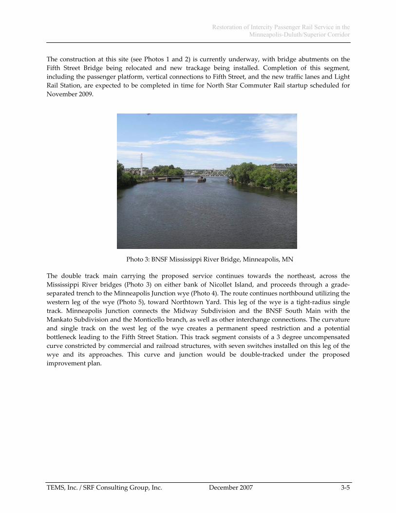
Photo 3: BNSF Mississippi River Bridge, Minneapolis, MN
The double track main carrying the proposed service continues towards the northeast, across the Mississippi River bridges (Photo 3) on either bank of Nicollet Island, and proceeds through a grade-separated trench to the Minneapolis Junction wye (Photo 4). The route continues northbound utilizing the western leg of the wye (Photo 5), toward Northtown Yard. This leg of the wye is a tight-radius single track. Minneapolis Junction connects the Midway Subdivision and the BNSF South Main with the Mankato Subdivision and the Monticello branch, as well as other interchange connections. The curvature and single track on the west leg of the wye creates a permanent speed restriction and a potential bottleneck leading to the Fifth Street Station. This track segment consists of a 3 degree uncompensated curve constricted by commercial and railroad structures, with seven switches installed on this leg of the wye and its approaches. This curve and junction would be double-tracked under the proposed improvement plan.

Restoration of Intercity Passenger Rail Service in the Minneapolis-Duluth/Superior Corridor
TEMS, Inc. / SRF Consulting Group, Inc. December 2007 3-6
Photo 4: Minneapolis Junction Wye, looking south towards Minneapolis, MN
Photo 5: West leg of Minneapolis Junction wye, looking north towards Northtown Yard.

Restoration of Intercity Passenger Rail Service in the Minneapolis-Duluth/Superior Corridor
TEMS, Inc. / SRF Consulting Group, Inc. December 2007 3-7
From Minneapolis Junction, the route follows BNSF trackage north to University Avenue (Photo 6). From University Avenue to Coon Creek Junction, the route follows the BNSF Seattle to Chicago mainline. This segment carries well over 60 trains per day on a partially double-tracked heavy-duty line, signaled with Centralized Traffic Control (CTC) controlled by BNSF operations personnel in Ft. Worth, Texas. Top speed for the majority of this line is 79 Miles per Hour for passenger trains, with Amtrak’s Empire Builder already operating over this segment once a day in each direction. This segment will also be shared with the North Star Commuter Rail service. Freight operations on this segment include switching, crew changes, and engine servicing and fueling at Northtown Yard (Photo 7).
Photo 6: Northtown Yard, Looking South towards University Avenue
Photo 7: South entrance to Northtown Yard, mainline on Left

Restoration of Intercity Passenger Rail Service in the Minneapolis-Duluth/Superior Corridor
TEMS, Inc. / SRF Consulting Group, Inc. December 2007 3-8
The route continues north on double track past Northtown yard, to the junction with the Duluth line at Coon Creek Junction. This section of track includes a possible site for the proposed Suburban North station in the City of Coon Rapids in Anoka County at the junction of Foley Boulevard, the 610 Freeway, and the BNSF mainline (see Exhibit 3.3). Compared to the alternative Anoka County site farther north at Andover, the Foley Boulevard site has the advantages of being directly connected to the Minneapolis outer ring road, and the station could also offer possible connectivity to North Star commuter rail. It currently is the site of a major Park and Ride lot with 3,200 parking spaces in a parking structure and transit station (see Photos 8 and 9).
Exhibit 3.3: Possible Suburban North Station at Foley Boulevard

Restoration of Intercity Passenger Rail Service in the Minneapolis-Duluth/Superior Corridor
TEMS, Inc. / SRF Consulting Group, Inc. December 2007 3-9
Photo 8: Foley Boulevard Grade Crossing
Photo 9: Foley Boulevard Park and Ride Facility

Restoration of Intercity Passenger Rail Service in the Minneapolis-Duluth/Superior Corridor
TEMS, Inc. / SRF Consulting Group, Inc. December 2007 3-10
3.1.2 BNSF Hinckley Subdivision
At Coon Creek Junction, the proposed route diverges onto the Hinckley sub-division single-track freight mainline to Boylston Junction. This track is controlled using Automatic Block Signaling, a basic form of occupied-block safety signal system, with train movements controlled by track warrants. Track warrants are basic operating permits allowing a specific train to operate over the sub-division, including detailed instructions for meets with trains in the opposing direction at passing sidings.
The track is maintained to FRA Class 3, which limits freight train speeds to 40 miles per hour and passenger trains to 50 miles per hour. (These speeds also limited the historic Amtrak passenger schedule on this route to 4 hours and 15 minutes.) Track condition is good, with welded rail throughout, but switches onto sidings and spurs are mostly Number 11 turnouts, limiting speed through sidings to 10 miles per hour.
Eleven passing sidings at approximately ten-mile spacing for train meets provide capacity for train meets. Nine are more than a mile in length, including five sidings that utilize powered automatic (remotely controlled) switches at both ends, and one siding equipped with a powered automatic switch at one end only. With the exception of Foxboro, all the powered switches are installed on sidings on the southern half of the line. The remaining sidings are equipped only with manually thrown switches, necessitating a train brakeman to walk the length of the train during passing meets in order to switch routes as the trains pass. These sidings are as follows:
Andover Automatic Bethel Manual Grasston Automatic Brook Park Automatic/Manual Hinckley Automatic Sandstone Manual Bruno Manual Nickerson Manual Foxboro Automatic
Freight traffic on this line averages twelve trains per day in both directions. While the majority of trains are short, 40-70 car trains operated by all three railroads, the line also sees one or more long (100+ car) unit trains per day carrying taconite, potash, sulfur, and coal. The longest trains can only use the five longest sidings, four of them in the southern half of the subdivision, that are equipped with powered, remotely controlled switches. These trains often require as much as eight hours to travel over the subdivision with multiple train meets.
Exhibit 3.4 shows the current track schematic for the Minneapolis to Duluth rail line. The Hinckley subdivision consists of the central portion of the line from Coon Creek (Photo 10 and 11) to Boylston.

Res
tora
tion
of In
terc
ity P
asse
nger
Rai
l Ser
vice
in th
e
Min
neap
olis
-Dul
uth/
Supe
rior C
orrid
or
TEM
S, In
c. /
SRF
Con
sulti
ng G
roup
, Inc
.
Dec
embe
r 200
7
3-
11
Exh
ibit
3.4
Base
Infra
stru
ctur
e an
d Si
ding
s

Restoration of Intercity Passenger Rail Service in the Minneapolis-Duluth/Superior Corridor
TEMS, Inc. / SRF Consulting Group, Inc. December 2007 3-12
Photo 10: Coon Creek Junction – Crossover to South Main
Photo 11: Coon Creek Junction – Hinckley Subdivision Begins
The mix of trains also varies widely on this subdivision. The two railroads with trackage rights on the line, Canadian Pacific and Union Pacific, each generates one mixed freight per day in each direction, plus some unit trains. BNSF averages one unit coal train per day and three other unit trains per day, principally taconite and potash. These normally operate at or near maximum allowable train length, with the controlling factor being siding lengths for passing. The other freights are a mix of mix carload traffic

Restoration of Intercity Passenger Rail Service in the Minneapolis-Duluth/Superior Corridor
TEMS, Inc. / SRF Consulting Group, Inc. December 2007 3-13
and local runs operated at shorter lengths and at varying speeds. While the shorter trains are reasonably quick and don’t contribute to traffic problems in the on-line communities, the long, heavily loaded unit trains at best have leisurely acceleration from stops in sidings or through restricted speed zones. These trains can block sidings and grade crossings, and take significantly longer to get across the subdivision.
The Hinckley Subdivision is laid with continuously welded rail, 133 pounds per yard weight, installed in 2004, spiked to conventional wooden crossties. The track is mounted in crushed rock ballast roadbed, with a substantial, raised sub-roadbed in most areas. The profile of the line can be described as generally flat and straight, rising gently from Minneapolis to the continental divide near Nickerson, which divides the St. Croix/Mississippi River watershed from the Lake Superior Watershed. From that point it descends gradually to the head of Lake Superior in Superior, Wisconsin and Duluth, Minnesota. There are several exceptions to this general description. Two significant two-degree curves lay just south of Hinckley, somewhat limiting the higher speed ranges envisioned, and a three-degree curve and bridge at Sandstone and a series of two and three-degree curves and high bridges north of Foxboro to Boylston have speed restrictions applied to them.
Photo 12: Andover Siding
Andover is the first siding north of Coon Creek Junction (Photo 12). This site is the first of five sidings with automatic switches at both ends. It also has three major highway grade crossings about one-half mile east of the City’s commercial district in essentially open countryside.

Restoration of Intercity Passenger Rail Service in the Minneapolis-Duluth/Superior Corridor
TEMS, Inc. / SRF Consulting Group, Inc. December 2007 3-14
Photo 13: Bethel Siding and Locomotive Repair Facility
Bethel is the next station to the north (Photo 13), and is an old, small city located on an east-west highway approximately equidistant between two rapidly growing Anoka County suburbs, East Bethel to the east on Highway 65, and Saint Francis to the west. It is the site of a small but successful locomotive repair and rebuild shop.
Photo 14: City of Isanti
Isanti is the next city on the line (Photo 14). It is five miles south of Cambridge and is the second largest city in Isanti County.

Restoration of Intercity Passenger Rail Service in the Minneapolis-Duluth/Superior Corridor
TEMS, Inc. / SRF Consulting Group, Inc. December 2007 3-15
Photo 15: City of Cambridge
Cambridge is one of two historic passenger rail stops (Photo 15) on the line between the Twin Cities and the Twin Ports, the other being Sandstone. It is Isanti County’s largest city and the county seat. Cambridge also has the second of four passing sidings with automatic switches at both ends. The city has several on-line shippers including a processing and a steel fabrication plant. Braham is the next City on the line, Isanti County’s third largest community. While it does not have a siding, it does straddle the railroad and Highway 65 at this point for several blocks. Grasston has the third siding with automatic switches at both ends.
Photo 16: Brook Park Siding

Restoration of Intercity Passenger Rail Service in the Minneapolis-Duluth/Superior Corridor
TEMS, Inc. / SRF Consulting Group, Inc. December 2007 3-16
After this, Brook Park (Photo 16) is the next station to the north. It has a three-degree curve ending underneath the Highway 23 overpass and leading into Mora Junction and a passing siding. Mora Junction connects the mainline with a largely unused and partially abandoned track going as far as the City of Mora, eleven miles to the east of Brook Park, and the county seat of Kanabek County. From here, the line leads roughly east-northeast to Hinckley.
Photo 17: Hinckley Siding
Just west of Hinckley is Hinckley siding (Photo 17), the fourth siding with a pair of automatic switches. The line crosses the junction with the “Rush Line”, a BNSF spur running south toward St. Paul and operated by the St. Croix Valley short line, and continues around a curve through the City of Hinckley, located on northern Pine County. A possible downtown Hinckley station site is approximately one-fourth mile west of I-35, and about one and one-half miles west of the Grand Hinckley Casino, run by the Mille Lacs Band of Ojibwe. The Casino is one of two run by the tribe. As one of northern Minnesota’s larger tourist draws, it hosts three and a half million guests per year.
Hinckley and Sandstone each have municipal train speed limits of 30 miles per hour. These restrictions are essentially irrelevant to freight operations because of physical limits in these two cities posed by sharp curves and trestles. However, these speed limits could restrict passenger train operations. Although these speed restrictions are considered unenforceable under current federal law, they are still relevant to the environmental planning process. Community concerns related to potentially higher passenger train speeds will need to be mitigated by grade crossing improvements and improved fencing to ensure community safety.

Restoration of Intercity Passenger Rail Service in the Minneapolis-Duluth/Superior Corridor
TEMS, Inc. / SRF Consulting Group, Inc. December 2007 3-17
Photo 18: Sandstone
Photo 19: Sandstone Curve
Sandstone is the next station to the north (Photo 18 and 19), with short, manually operated siding, a sharp three-degree curve, and a high trestle over the Kettle River (Photo 20), a wild and scenic river. As the largest city in northern Pine County, with medical, county, retail, and commercial services, Sandstone is the regional center for the area and is considered the gateway to several parks and recreational areas.

Restoration of Intercity Passenger Rail Service in the Minneapolis-Duluth/Superior Corridor
TEMS, Inc. / SRF Consulting Group, Inc. December 2007 3-18
Photo 20: Kettle River Trestle, Sandstone
Photo 21: Askov Depot and Siding
The next station is Askov (Photo 21), a small city at the junction of State Highway 23 and two County highways. It contains the only surviving station structure on the Hinckley subdivision, and has an on-line feed mill. Askov has a manually operated one and one-half mile long siding.

Restoration of Intercity Passenger Rail Service in the Minneapolis-Duluth/Superior Corridor
TEMS, Inc. / SRF Consulting Group, Inc. December 2007 3-19
Photo 22: Bruno Siding
Photo 23: Holyoke Trestle - Nickerson
The next two points to the north are the hamlets of Bruno and Nickerson (Photos 22 and 23). Each has a one and one-half mile long siding equipped with manual switches.

Restoration of Intercity Passenger Rail Service in the Minneapolis-Duluth/Superior Corridor
TEMS, Inc. / SRF Consulting Group, Inc. December 2007 3-20
Photo 24: Foxboro Siding
Photo 25: Nemadji River Trestle
The last and northernmost siding on the Hinckley subdivision is Foxboro, an abandoned town site (Photo 24). It has the fifth passing siding equipped with automatic switches. Immediately to the north of Foxboro lie a series of curves, including five two and one-half degree and two three degree curves, three small bridges, and two high trestles crossing the Black and Nemaji Rivers (Photo 25). North of Foxboro and extending to Boylston, another restricted speed zone exists, again because of the sharp curves and several high trestles. Directly north of the Nemadji River trestle, the line connects at Boylston Junction into BNSF’s Staples Division mainline from North Dakota, a double tracked, heavily used mainline into the Twin Ports.

Restoration of Intercity Passenger Rail Service in the Minneapolis-Duluth/Superior Corridor
TEMS, Inc. / SRF Consulting Group, Inc. December 2007 3-21
3.1.3 BNSF Duluth-Superior Area
At Boylston, the route merges with BNSF’s mainline from North Dakota. This line sees 30-40 trains per day on average, and is double tracked and CTC controlled past the Canadian National interchange at Saunders (Photo 26) and into the Superior, Wisconsin freight yards.
Photo 26: CN Interchange at Saunders Junction
At Central Avenue near South Superior, the mainline continues north into the former Great Northern Railroad yards, while a bypass diverges around the east side of the yards. This ex-Northern Pacific line, known as the “Coal Runner”, follows the historic passenger mainline and allows frequent (daily or more often) loaded coal trains direct access to the Midwest Energy power-plant and docks north of the yards. This line is straight and flat for four miles through the city, with very limited grade crossings, but is often used to temporarily hold or store 125-car coal trains until Midwest Energy has space or time to unload them. At the north end of the Coal Runner is the site of the privately preserved Great Northern’s Superior Union Depot (Photo 27).
Immediately beyond this point at the Winter Street grade crossing, the line enters a maze of track switches and crossings (“diamonds”) at the north end of the BNSF yards called LST&T (Lake Superior Terminal & Transfer) Junction (Photo 28), curving sharply to the left. With connections to Midwest Energy and several other lines connecting CP and UP tracks and yards in Superior, this connection track is restricted to 10 miles per hour. This track work alternates between severe curves, short tangents, diamonds, and switches for several hundred yards. It crosses both the north lead tracks into the Superior freight yards and the approach tracks for the Midwest Energy unloading loop.

Restoration of Intercity Passenger Rail Service in the Minneapolis-Duluth/Superior Corridor
TEMS, Inc. / SRF Consulting Group, Inc. December 2007 3-22
Photo 27: Superior, Wisconsin, Great Northern Union Depot
Photo 28: LST&T Junction
From LST&T junction, the route continues due west with a 35 mile per hour restriction across the Grassy Point Draw Bridge over St. Louis bay (Photo 29), and then turns to the north-east toward the Duluth Union Depot. Beyond the bridge, the route continues on the east leg of a wye past Mike’s Yard (Photo 30) and on toward Rice’s Point Yard serving the Port of Duluth’s complex of docks and elevators.

Restoration of Intercity Passenger Rail Service in the Minneapolis-Duluth/Superior Corridor
TEMS, Inc. / SRF Consulting Group, Inc. December 2007 3-23
Photo 29: Grassy Point Draw Bridge, St. Louis Bay
Photo 30: North end, Grassy Point Draw Bridge (BNSF Mike’s Yard)
All the trackage on the north shore of St. Louis Bay is designated as yard limits, restricting speeds to no more than 10 to 25 miles per hour. This portion of the line is notable for numerous switches, irregular profiles, slow speed running within yard limits without signals, and conflicts with freight and switching moves. While few grade crossings exist on this three and one-half mile segment leading to Duluth Union Depot, the track includes a major interchange with the Canadian National near the former DM&IR Ore Docks, and also serves as a yard lead for Rice’s Point Yard and numerous industrial spurs.

Restoration of Intercity Passenger Rail Service in the Minneapolis-Duluth/Superior Corridor
TEMS, Inc. / SRF Consulting Group, Inc. December 2007 3-24
Photo 31: Duluth Union Depot
Beyond the Rice’s Point wye, the line into the Duluth Union Depot (Photo 31) is single-track, lightly maintained track, ending at the stub-end platform tracks to the south of the Depot’s train-shed, currently in use as a cultural arts center and railroad museum. Immediately to the west of the Depot, it crosses a large open area that once housed passenger car servicing and storage yards for the Great Northern Union Depot and the Omaha Road Passenger Depot immediately to the south of this yard.
3.1.4 Canadian National’s Steelton Subdivision
As shown in Exhibit 3.5, an alternate route through the Twin Ports area would use the Canadian National mainline from Saunders through Steelton, reconnecting to the line to downtown Duluth in the vicinity of Mike’s Yard, just north of the Grassy Point Draw. Passenger trains using this route would bypass downtown Superior, Wisconsin, but suburban stops could be provided in West Duluth and South Superior. Besides offering an alternate route for passenger trains, the line could serve an important strategic and operational purpose for freight traffic. This line serves as the only direct route linking Rice’s Point Yard at the Port of Duluth to CN’s carload freight yard at Pokegama. For better compatibility with the CN directional running arrangements north of Duluth, the Steelton Subdivision could also provide an alternative to the Proctor Hill line for CN unit train traffic to and from the Port of Duluth.
From Saunders to Steelton Junction, the route is part of CN’s mainline from Canada to Chicago. It is partially double tracked and signaled with CTC, usually handling in excess of 25 trains per day. Three miles to the west of Saunders is CN’s Pokegama Yard, a major and new facility for train marshalling and servicing. The mainline past the yard is double tracked, eliminating the need for restricted speeds. The line transitions to a single track mainline, crossing the St. Louis River on the historic Oliver Road/Rail Bridge (Photo 32) and one other high trestle with a 35 mile per hour speed restriction, into Steelton Yard, a collection of train-length running and passing tracks at the base of the major grade leading to the Iron Range. Besides the Grassy Point Draw, the Oliver Bridge is the only other St. Louis River crossing in the Twin Ports area that could carry north-south traffic between Wisconsin and Minnesota. Currently this line and bridge also carries BNSF trains to Minnesota and Canada via trackage rights.

Restoration of Intercity Passenger Rail Service in the Minneapolis-Duluth/Superior Corridor
TEMS, Inc. / SRF Consulting Group, Inc. December 2007 3-25
Exhibit 3.5: Map of the Twin Ports – Potential Routes
At Steelton Yard, the route into downtown Duluth diverges onto the Duluth Transfer Railway. This track is owned by the CN for the next three miles connecting to BNSF trackage running southwest from Grassy Point Draw. The CN line had been maintained at FRA Class 1 standards (10 miles per hour) until drainage and culvert issue at one site caused CN to take the line out of service. The line itself retains a good roadbed and is relatively unencumbered by grade crossings or any other right of way intrusions, and would offer an alternative routing to CN and BNSF in the event of any bridge or track problems in Superior or at Grassy Point. The CN portion of the line from Steelton towards Grassy Point is currently out of service pending sale to the Regional Railroad Authority for preservation and rehabilitation.

Restoration of Intercity Passenger Rail Service in the Minneapolis-Duluth/Superior Corridor
TEMS, Inc. / SRF Consulting Group, Inc. December 2007 3-26
Photo 32: Oliver Bridge
3.2 Engineering Standards and Specifications
3.2.1 Track Condition and Allowable Speeds
Top speeds and speed restrictions for all train operations, passenger and freight, are regulated by the Federal Railroad Administration (FRA), based on a well-established set of civil engineering criteria and a proven, necessarily conservative body of knowledge concerning the physics of railroad vehicle and track dynamics. The FRA is the governing body for all railroad operating matters, especially safety, common standards, inspections, and operating regulation, based on the federal governments constitutional authority to control and regulate interstate commerce.
The FRA classifies track condition and allowable speed over that track by a series of Classes. Each FRA Class carries with it specific standards for roadbed condition, crosstie and rail condition, maintenance and inspection, and alignment and consistency of the track surface. Two top speeds are normally quoted, one for freight train maximum speeds, and a higher one for passenger train maximum speeds. This recognizes the generally higher tolerances of passenger equipment to tipping and rolling stock condition, based on lower centers of gravity, lighter loads, and more frequent inspections. For instance, FRA Class 3, the current standard in effect on the Hinckley Subdivision, allows a maximum speed of 40 Miles per Hour for freight. BNSF’s posted speed limit is 50 miles per hour for passenger trains. Exhibit 3.6 illustrates the Class limits on passenger train speeds, and the allowable tolerances for rail surface misalignment (bends, kinks, worn spots, etc.) over a 60 foot distance, that are applicable for this route.

Restoration of Intercity Passenger Rail Service in the Minneapolis-Duluth/Superior Corridor
TEMS, Inc. / SRF Consulting Group, Inc. December 2007 3-27
Exhibit 3.6: FRA Track Classifications and Allowable Tolerances
FRA Class Maximum Passenger Speed
Rail Surface Tolerance +/- inches per 60 feet
Class 3 60 mph 1 3/4 inch
Class 4 80 mph 1 1/2 inch
Class 5 90 mph 5/8 inch
Class 6 110 mph 3/8 inch
Class 7 125 mph 1/4 inch
3.2.2: Track Curvature and Right-of-Way Alignments
Track curvature is normally expressed in degrees. Two measures can actually be used to determine the degree of curvature. The first is the number of degrees of rotation from a tangent or straight line that the track curves in 100 feet length. The second measure is the inches of variation on the outer rail from the center of a 60-foot chord stretched along the track. For the wide curves employed in railroad track, these two measures are essentially equal. Curves in a slow-speed yard environment may be as tight as 12 to 15 degrees, with 15 degrees representing the practical sharpest radius of curves used by modern heavy-duty freight locomotives. Mainline track generally is laid at three degrees of curvature or less, in the interest of maximizing allowable speed and minimizing friction and drag.
Exhibit 3.7 illustrates the range of curvature involved on mainlines covered by the study, with the maximum radius of slightly over three degrees occurring at Hinckley and Sandstone. Other curves of over two degrees, thirty minutes occur at Brook Park and between Foxboro and Boylston. These curves will generate speed restrictions even on Class 3 track, while most other curves on the Hinckley Subdivision are near one degree, and do not impose a speed penalty at most speeds.
Exhibit 3.7: Curve Degrees versus Radius
Degree Radius
1 5,730 feet
2 2,865 feet
3 1,910 feet
4 1,433 feet
Note, the very large difference in radius between a three degree and a one degree curve, is about three-quarters of a mile. In almost all cases, while a restrictive curve can be eased to a larger radius to increase running speeds, the “easing process” is limited by the existing right-of-way. If a new alignment is required, the acquisition of an entirely new right of way could raise significant environmental issues. Because of topography, wetlands and streams, and physical barriers (such as the highway overpass at Brook Park), the realignment of curves becomes an expensive process.

Restoration of Intercity Passenger Rail Service in the Minneapolis-Duluth/Superior Corridor
TEMS, Inc. / SRF Consulting Group, Inc. December 2007 3-28
3.2.3: Track Super-Elevation in Curves and Relation to Speed
Another means for increasing speed through curves is to cant or bank the track, as on a highway curve or a speedway embankment. This is known as super-elevation on a railroad curve.1 It is measured in inches of difference between the inner and outer rail, based on a level line across the rails. The banking offsets the train’s centrifugal force in the curve with an offset in the car’s center of gravity. Significant speed improvements can result, especially for passenger equipment. The stable characteristics of passenger equipment allow for under-balancing or “cant deficiency,” which allows a train to go around a curve faster than its balancing speed. Riders on the train would then feel a centrifugal force towards the outside of the curve. However, excessive super-elevation can create a tipping force on slow freight trains towards the inside of the curve. This can lead to excessive wear on the inside rail and a shift in the rail and roadbed, where the inner rail sinks further because of loads and impacts, worsening the effect. In extreme cases, it could cause slow-speed derailments in the curve. BNSF’s current standard for the Duluth line is one and one-half inches maximum super-elevation, while passenger and high-speed freight mains are often laid with five or six inches of super-elevation. Exhibit 3.8 illustrates the effect of varying applications of super-elevation on freight and passenger train speeds. Exhibit 3.9 shows the maximum speed for a modern train equipped with a passive tilt system, such as the Talgo T21 that was assumed in the performance analysis for this study. Speeds for a conventional non-tilting train would be slower, while speeds for an active-tilt train if it could operate with more than 6” cant deficiency, could be slightly faster.
Exhibit 3.8: Freight Reference Speeds Curve Superelevation Adjustments
Degree of Curve
1 2 3 0 60 mph 42 mph 35 mph
1 71 mph 50 mph 41 mph
1.5 76 mph 53 mph 44 mph
2 80 mph 57 mph 46 mph
3 89 mph 63 mph 51 mph
4 96 mph 68 mph 56 mph
5 104 mph 73 mph 60 mph Supe
rele
vatio
n (in
ches
)
6 110 mph 78 mph 64 mph
Note: Superelevation above is the "Actual Superelevation" and "Superelevation Under balance" is assumed to be 2.5-inches
1 See: http://www.interfacejournal.com/features/01-06/superele/1.html

Restoration of Intercity Passenger Rail Service in the Minneapolis-Duluth/Superior Corridor
TEMS, Inc. / SRF Consulting Group, Inc. December 2007 3-29
Exhibit 3.9: Passenger Reference Speeds Curve Superelevation Adjustments
Degree of Curve
1 2 3
0 93 mph 65 mph 53 mph
1 100 mph 71 mph 58 mph
1.5 104 mph 73 mph 60 mph
2 107 mph 76 mph 62 mph
3 113 mph 80 mph 65 mph
4 120 mph 85 mph 69 mph
5 125 mph 89 mph 72 mph
Sup
erel
evat
ion
(inch
es)
6 131 mph 93 mph 76 mph
Note: Superelevation above is the "Actual Superelevation" and Passenger "Superelevation Under balance" is assumed to be 6.0-inches for Passive Tilt Equipment
An additional engineering feature of curves on high speed track is a spiral. This is simply a transition area coming into and out of a curve. Spirals reduce the impact of the curvature gradually reducing tightness so that there is not a sudden lurch or sideways acceleration caused by an abrupt change. Properly designed spirals permit curves to be operated at maximum speed according to the above tables. Improperly designed spirals can limit trains to slower speeds. Gradual spirals are also necessary for both freight ride quality and for passenger comfort, and are incorporated in the cost estimate for track resurfacing and improvement for this project.
3.2.4: Switches and Crossovers
Track switches or turnouts allow trains to change routes where tracks diverge from one to another. This is accomplished by the simple expedient of moving a set of intermediate rails, or points, towards the direction of the desired route. A fixed casting, call a “frog” allows the car wheels to pass over the inner rails where they cross in the middle of the turnout.
In the simplest turnouts, bending or aligning the points is done manually by pulling a moveable lever or handle that operates a bar or cam, and can be locked in place to fix the selected route. Remote applications and installations designed to save time and labor now employ electric, pneumatic, or hydraulic powered switch machines to automatically align the switches by remote control. Modern applications on high volume lines also tie the direction of the switch into both a signal aspect and into the dispatch and control system, such as CTC or PTC, and provide safety interlocks. In signaled territory, manual switches can be fitted with an electric lock, which does not throw the switch, but does prevent its change until the dispatcher or signal system allows it.
Track switches are designated by a number system. One number essentially means that the track is diverging at a rate of one inch for every ten inches of length on the straight side of the switch. Thus, a No. 11 switch, the most commonly used switch on this route, would have a length of 52 feet from switch
Restoration of Intercity Passenger Rail Service in the Minneapolis-Duluth/Superior Corridor
TEMS, Inc. / SRF Consulting Group, Inc. December 2007 3-30
points to frog. The recurved or transition track to meet a parallel siding track would add another approximately 100 feet to the installation. The speed limit on a diverging route, such as onto a siding, is 10 miles per hour through a No. 11 switch. Current BNSF practice for mainline turnouts on unit train corridors and high speed applications is a No. 24 turnout, with a basic length of 113 feet, a total installation length of about 300 to 350 feet, and a control speed over the diverging route of 45 miles per hour. This increase in speed has two effects. First, a loaded train does not have to do most of its braking, deceleration, and acceleration on the mainline, but can moderate train speed once it is into an extended siding. Second, on double track or a sufficiently extended siding, the freight train can keep moving at a reduced speed. This eliminates the need for a full stop and potentially a full brake application, which in turn may drop pressure in the air brake line to the point where the locomotive compressors need to re-pressurize all of the train’s brake cylinders. This can add 10 to 20 minutes on that train’s schedule and hamper the fluidity of the line’s operations.
In line with the above discussion, except as otherwise specified, the construction assumptions for the route include No. 24 powered automatic switches for all mainline applications, and No. 20 or No. 11 switches for spurs and industrial sidings, with electric locks on all switches diverging from a mainline or siding. Unit construction costs include the powered switch machine or lock, materials and components for the track turnout, and construction and installation on site or in place.
Crossovers are essentially two paired turnouts allowing a train to pass from one track on a double track main to the other track. The switch geometry on each side of the crossover is approximately the same as a single turnout, but the crossover must be designed and constructed as a unit. Aligning the pair of switch points along with all signal activation must be accomplished with either mechanical or electric interlocking controls so that the crossover switches move in concert.
3.2.5: Clearances and Track Spacing
Longer and heavier cars, faster trains, safety and hazardous materials considerations, and increased track maintenance needs have all raised the need for greater clearances alongside and over current mainline tracks. BNSF currently requires a 23.5-foot vertical clearance above the railhead for any obstacles crossing over the tracks, including power lines and bridges. Horizontal clearance is generally set at 50 feet from track center, or 25 feet with crash barriers at all intruding structures, such as bridge abutments. This impacts the costs of certain construction elements, such as the size of bridges at grade separations, and new track construction at obstacles like the Duluth iron ore docks.
Railroad regulations call for 14-ft spacing of tracks. However, BNSF also now normally specifies 25-foot center-to-center track spacing on new double track, both for safety clearance, and to allow track gangs unimpeded access to one of the two tracks at any time. While most of the right-of-way on this route is 100-feet wide or more, and could accommodate much of the track construction, this does not protect from environmental impacts on or off the property.
Typically it is feasible to adhere to this 25-foot track spacing standard in open country, but trying to apply it everywhere may unnecessarily increase the roadbed intrusion into adjacent wetlands or sensitive urban environments. In cases where adhering to the 25-foot standard would conflict with physical barriers or would impose excessive cost or environmental impact, it may be necessary to reduce the track centers to the normal 14-foot spacing. Conversely, increasing the track spacing from 25-feet to 28-feet could preserve the flexibility, at minimum cost, to add a third track in the middle later.

Restoration of Intercity Passenger Rail Service in the Minneapolis-Duluth/Superior Corridor
TEMS, Inc. / SRF Consulting Group, Inc. December 2007 3-31
Where possible, the 25-foot center-to-center track spacing BNSF standard was used for the development of feasibility-level construction and environmental review assumptions for this study.
3.2.6: Crossing and Signal Improvements to Allow 79 mph Operations
Highway/Rail Grade Crossing Warning Systems There are 182 highway rail grade crossings in this corridor. Currently, 61 have active warning devices. This study assumes that all 91 of the public crossings will require complete replacement of the crossing warning systems and the remaining crossings are acceptable without upgrade. It will be a final design requirement to perform a diagnostic at each of these 182 crossings to determine the appropriate site specific safety measures that will allow greater speeds over the crossing.
The estimate is based on the assumption of using industry standard and proven constant warning time devices, flashers, and gates. Quiet zone implementation at any on-line location would entail a further phase of project development, including administrative, regulatory, and construction activity. The upgraded gates and flashers, equipped with Constant Warning Time detection circuitry, would need to be supplemented by positive traffic control measures such as raised medians, signage, and road access design changes. These would involve relatively minor capital improvements in most circumstances, above and beyond the planned upgrades. Cities would then need to petition the Federal Railroad Administration, the railroad, and the state DOT under 49 CFR Parts 222 and 229 to approve and implement the quiet zone.
The base estimate for crossings to be replaced is based on typical 2007 costs indexed at an annual inflation rate of 4 percent with expected construction in 2010.
Train Control Signal Systems In order to increase speeds and throughput on this corridor most sidings have been significantly extended to provide a number of opportunities for running meets and passing moves. This requires the reconstruction of all the existing interlocking and most likely all the existing intermediate signal locations. It is also necessary to provide control at each interlocking (end of siding) to maximize the use of the track infrastructure so this estimate is based on the assumption the corridor will be upgraded to Centralized Traffic Control (CTC).
It is anticipated that the new CTC system will be based on conventional wayside signaling technology. This involves vital controllers at each control point (end of siding or interlocking), track circuits that monitor block occupancies and send vital aspect information, wayside signals for governing train movements, power switches for remote route control, electric switch locks for control of manual switches, and systems for detecting onboard equipment defects such as hot journal bearings or shifted loads.
The heart of a CTC system is a vital controller. This controller takes route and switch alignment requests from the remote dispatching system in Ft. Worth via a communications link. A combination of radio and leased telephone lines are assumed to be the communications means. After confirming appropriate block occupancies, verifying any conflicting time our route locking has expired, and setting conflicting moves to stop, the vital controller aligns the power switch and locks in the requested route. It then sets the wayside signals it controls to permit the requested movement. The track circuits continuously convey the signal and route aspects via on-track coded pulses to downstream intermediate or control point signals.
Restoration of Intercity Passenger Rail Service in the Minneapolis-Duluth/Superior Corridor
TEMS, Inc. / SRF Consulting Group, Inc. December 2007 3-32
There may be an opportunity to realize a cost savings if CTC and PTC systems were installed at the same time. However, this report conservatively assumes the cost of a full conventional CTC installation followed up by the cost for installing a separate PTC system as an overlay.
3.2.7: Crossing and Signal Improvements to Allow 110 mph Operations
Modern train control and communication systems safely coordinate train operations to permit bi-directional use of a track network. On heavily used lines, railroads install Centralized Traffic Control (CTC) to maximize track capacity. CTC is system of signal blocks, track circuits, controlled switches, wayside signals (or cab signals), interlockings and communications to a central control facility that enable trains moving in a common direction to follow closely on a common main track or pass opposite direction traffic on siding tracks. Under CTC, a remotely located dispatcher can set and optimize train routing. However, train speeds are limited to 79-mph. In-cab signal displays and advanced grade crossing warning systems are required for speeds above 79-mph.
Highway/Rail Grade Crossing Warning Systems
The treatment of grade crossings to accommodate trains with a speed over 110-mph is a major challenge to planning a high-speed rail system. Highway/railroad crossing safety play a critical role in future project development phases and a variety of devices have been considered to improve safety including roadway geometric improvements, median barriers, barrier gates, traffic channelization devices, wayside horns, fencing and the potential closure of crossings.
FRA regulations require the use of four quadrant gates with constant warning time activation at public crossings subject to 110-mph passenger operations. Constant-warning time systems are essential to accommodate the large differential in speed between freight and passenger trains. The treatment and design of improved safety and warning devices will need further development during the PEIS process to identify specifications and various approaches to determine the treatment of specific crossings. As in the 79 mph scenario, a diagnostic site survey will be required at each crossing (public or private) to determine the appropriate site-specific safety measures for allowing 110 mph speeds over the crossing.
Train Control Signal Systems
FRA regulations require that trains operating in excess of 79-mph, employ advanced signal systems that provide cab signaling and automatic train protection or automatic train stop functions. Such track circuit based systems in use today are very expensive to construct and maintain. In efforts to develop a more cost effective technology, the FRA and industry have turned to Positive Train Control (PTC), a communication based strategy that does not depend on track circuits to establish train location. For speeds above 79-mph, a PTC system will be required to provide an in cab display of key track conditions (block speed, signal and route status, grade crossing activation status, alarm notifications, etc.) and enforce speed and signal compliance.
Many suppliers are currently pursuing development of PTC systems and are proposing a variety of different technical architectures and operational plans. There are coalitions and groups of different forms made up of railroads, regulators, and suppliers attempting to define and refine PTC requirements and establish standards.

Restoration of Intercity Passenger Rail Service in the Minneapolis-Duluth/Superior Corridor
TEMS, Inc. / SRF Consulting Group, Inc. December 2007 3-33
For example, the ITCS vital system produced by General Electric builds on their proven wayside and cab signaling systems. Vital approaches to PTC incorporate embedded and certified safety logic, so the train engineer can rely on the indications and authorities provided by the automated system. No manual intervention is necessary, and track movement authorities conveyed through the system are actionable and authoritative. ITCS is currently operating in revenue service under an FRA waiver in Michigan. ITCS also incorporates speed regulation and highway grade crossing system status that provide all of the PTC features needed to support 110-mph operations. BNSF would have to file a Product Safety Plan (PSP) for gaining FRA approval for deployment of ITCS, or any similar new vital PTC technology, on the Minneapolis-Duluth line.
Another PTC option (which is really not an option for 110-mph passenger train speeds) is BNSF’s non-vital ETMS system produced by WABTEC. Non-vital systems are not fully safety-certified, thus any recommendations are considered purely advisory in nature. As a result, these systems can only be applied to unsignalled territory such as branch lines and are not applicable for main line operations. However, WABTEC is pursuing vital PTC for the UP and NS railroads. They expect to be in deployment test by 2008 under FRA waivers, and have their Product Safety Plans approved by the FRA in 2009, and begin revenue service upon this approval. The UP and NS systems will be an overlay on top of conventional CTC signaling, and will capable of conveying signal aspects and movement authorities.
Although ETMS in its current form cannot support speeds higher than 79-mph, other PTC systems under development can do so. At the present time, even WABTEC’s own systems are not fully interoperable or compatible with one another, let alone with the systems developed by different signal vendors.
Therefore, the signal supply industry is currently partnering on an “Interoperable Communications Based Signaling (ICBS) Test Project” co-sponsored by the FRA and AREMA Committee 37.2 This test will demonstrate a stand-alone vital, signals-based PTC architecture capable of providing the kind of cab signal information needed to support 110-mph operations in the Minneapolis-Duluth/Superior Corridor. Since the architecture and operating principles are the same, it can also act cooperatively within an existing CTC system to allow for mixed-mode operation until the locomotive fleet can be fully equipped. Draft standards for PTC architecture and communication protocols are already over 90% complete, so by December 2008, the ICBS project will prove, in a test-bench environment, the interoperability of different suppliers’ PTC hardware and software. The FRA has agreed to provide a $500,000 funding grant in support of this effort. 3
For progress to continue there is a need for supplemental R&D funding to promptly follow up the results of this test-bench demonstration with a real-world pilot project. The Minneapolis-Duluth/Superior Corridor would offer an ideal environment for advancing such an "Interoperable PTC Pilot Project." Such a pilot would demonstrate the ability of three major Class I railroads and all the signal system suppliers to work together to demonstrate a fully interoperable and vital PTC system, implementing the industry-standard system architecture and communication protocols that are now being finalized by the Committee 37 working group.
The development of an accepted standard for interoperable, vital, and signals-based PTC would serve a strong U.S. national interest. It has therefore been proposed that the FRA fund an "Interoperable PTC Pilot Project" using the Minneapolis-Duluth/Superior Corridor as a test-bed. 2 See: http://grouper.ieee.org/groups/railtransit/wg2/Archive Other/2007 AREMA CBS paper Vital PTC V2.pdf and http://www.nxtbook.com/nxtbooks/sb/ra0707/index.php?startpage=81 3 See: http://www.progressiverailroading.com/freightnews/article.asp?id=11499 and http://www.billpetit.com/icbs.html

Restoration of Intercity Passenger Rail Service in the Minneapolis-Duluth/Superior Corridor
TEMS, Inc. / SRF Consulting Group, Inc. December 2007 3-34
The technical feasibility of the kind of PTC solution needed to support 110-mph operations in the Minneapolis-Duluth/Superior Corridor has already been well established by the success of General Electric’s ITCS system in Michigan. Only the compatibility issues between ITCS and BNSF’s ETMS system still remain to be resolved. By leveraging the current AREMA Committee 37 effort, and based on the FRA’s expected support for funding continued development of interoperable, vital PTC systems, it is expected that the remaining technical issues regarding the interoperability of these systems can be resolved in a time frame that they will not delay the ability to implement 110-mph rail service in the corridor.
3.3 Intercity Passenger Train Strategies
Based on the project scenarios and assumptions, four basic capital cost estimates have been developed for increasing speeds and train frequencies. Efforts were made to treat similar costs and project components consistently between estimates, and also to be consistent with external projects, such as North Star Commuter Rail, where applicable.
Project construction zones, i.e. sidings and double tracking, are identified by specific railroad mileposts and located on the project summary maps for reference. Other components are designated by type of investment in the titles and headings, such as track upgrades and signaling.
3.3.1: Methodology
Several resources were employed for determining operating scenarios; construction and equipment needs, and have developed a catalog of relevant information to formulate accurate approximations of costs for this feasibility study. All three of the consulting partners have extensive experience in freight and passenger rail operations, economics, engineering, construction, and costs. Using this background as a foundation, industry contacts were made to validate each aspect of the Study. Regional passenger rail operations were researched and surveyed to get input from current similar projects, including personal interviews with several management representatives. These included the Pacific Northwest Passenger Rail project, including the Cascades and West Coast Express trains, the Illinois State regional rail system, and the Trinity Express commuter rail project in Texas. Input was also garnered from several state DOT’s active in rail, and Amtrak. Further research and validation was done utilizing several high-speed rail studies in the United States, as well as European experience. Industry associations, including AREMA, APTA, and AASHTO were consulted on funding, operational, technology, and engineering data. Finally, industry suppliers and vendors have been contacted about costs, availability, and applications for actual system components from grade crossing and signal systems to track work and maintenance. The following portions of the Study detail these findings.
3.3.2: Alternative Investment Scenarios
For the purposes of both the ridership and revenue forecasts, and estimating the needed infrastructure improvements and capital investments for the Study, the following scenarios were selected for quantification. The improvements build-up moving to higher options in the sense that an investments included in any lower option are also included in the higher options. However, the cost estimates derived for each of these scenarios represents the total investment for that scenario, and are not cumulative with any other investment scenario. Detailed cost sheets for each scenario will be found in Appendix A.

Restoration of Intercity Passenger Rail Service in the Minneapolis-Duluth/Superior Corridor
TEMS, Inc. / SRF Consulting Group, Inc. December 2007 3-35
Option 79/1: 1 Round Trip per Day, 79 Miles per Hour
Option 79/4: 4 Round Trips per Day, 79 Miles per Hour
Option 110: 4-8 Round Trips per Day, 110 Miles per Hour
Option 125: 4-8 Round Trips per Day, 125 Miles per Hour
Option 79/1: This option was studied as a minimum investment scenario, based on initial contacts with BNSF management and a subsequent construction quote from the railroad for upgrading the FRA condition of the Hinckley subdivision from Class 3, with a 50 mph top speed, to Class 4, 80 mph top speed (79 mph regulated top speed per BNSF operating rules). The railroad quote was approximately $23,000,000 for resurfacing the track to Class 4 standards, including ballast and tie cleaning, inspection, and replacements, and selected minor improvements as needed to recalibrate grade crossing detection and other signaling issues. No signal upgrades were assumed, and the single round trip would operate under track warrant as per current freight operations on this middle segment.
The one round trip per day would also not trigger any necessity for improvements in the Minneapolis leg of the route above and beyond the North Star upgrades. A severe schedule penalty due to the slow and unpredictable conditions in Superior and Duluth was deemed unacceptable, with slow running and possible delays routinely adding 30 minutes or more per each trip. An engineering estimate was derived from a conceptual design to double track a portion of the Coal Runner, and install a passenger main to bypass Berwind and Rice’s Point Yards in Duluth. Track would be upgraded to Class 4, with a targeted top speed of at least 60 mph on these two segments after allowing for safety considerations of speed differentials in the yard areas.
Option 79/4: This option allowed for a more complete estimate of engineering costs for a comprehensive upgrade to support multiple daily trips at 79 mph. In addition to all the 79/1 upgrades, the current ABS block signals and track warrant system would be replaced with CTC. All grade crossings would be evaluated and upgraded to maintain or increase safety at the crossing in light of the multiple higher speed events at each crossing. This would include Constant Warning Time train sensing to activate the gates and flashers, additional gate installations, and extension of positive crossing protection (gates and flashers) to a majority of public crossings. Private crossings would be evaluated and upgraded as appropriate. Limited portions of the line, particularly in populated areas, will be fenced. Key passing sidings would be lengthened, and switches would be powered and upgraded to Number 24, per BNSF current mainline standards for unit train service and increased speed through switches. Upgrades in the Minneapolis area would include a third mainline track at Northtown yard, double tracking of the west leg of the Minneapolis Junction wye, and a stub end terminal at Fifth Street station to improve capacity and flexibility.
Option 110: In addition, to all the 79/4 upgrades, track resurfacing and upgrade would be performed to meet FRA Class 6 standards. Three 10-mile segments of double track would be added to the Hinckley Subdivision to permit opposing and overtaking meets at speed. These double track extensions and upgrades would be supplemented by a new siding in Braham to add more freight capacity. The CTC signal system would be supplemented by a Positive Train Control (PTC) system with locomotive cab indications, positive automatic train stop, and integrated grade crossing status and activation built into the PTC. Grade crossings will be upgraded to achieve a “sealed” corridor, with Quad gates, medians,

Restoration of Intercity Passenger Rail Service in the Minneapolis-Duluth/Superior Corridor
TEMS, Inc. / SRF Consulting Group, Inc. December 2007 3-36
traffic controls, and vehicle intrusion detectors installed at most public crossing, and gates and flashers at private crossings. Grade crossings would be evaluated for some possible closures, and grade separations if necessary. Fencing would be installed on all high-speed segments of the route.
Option 125: Track will be upgraded to FRA Class 7. All siding extensions, double tracking, and other capacity upgrades for option 110 would apply to this scenario. The high speed segments would be closed to achieve a “fully separated” corridor, with major applications of grade separations, closings, and barrier gates designed to positively lock and prevent vehicle intrusion (in case of a collision with the barrier) at lightly used but necessary crossings. Full fencing would apply.
3.3.3: Other Assumptions
All station sites will be supplied with basic access, platforms, and a single point ADA loading accommodation (Ramp, bridge, or lift). Further station development will be planned and undertaken by the local jurisdiction to meet their needs as appropriate.
The maximum track speeds regulated by FRA conditions and railroad operating rules, and the improvement of some key line segments under other independent projects, play a part in focusing on areas covered by the project needing capital investment and upgrades. This in turn is a pre-requisite for accurately costing various project components. Toward this end, a speed and mileage chart was compiled for the three basic construction levels that emerged as the engineering approach was formulated, as shown in Exhibit 3.10. These speeds do not reflect curve speed limits, which are calculated automatically by the LOCOMOTIONTM software. LOCOMOTION™ is a Train Performance Calculator program that uses the track curve, grade and speed limit data, along with the physical acceleration and deceleration characteristics of the train, for calculating the train’s speed and operating timetables across any segment of track.

Restoration of Intercity Passenger Rail Service in the Minneapolis-Duluth/Superior Corridor
TEMS, Inc. / SRF Consulting Group, Inc. December 2007 3-37
Exhibit 3.10: Minneapolis-Duluth/Superior Passenger Rail Feasibility Study Engineering Regulated Speed Profile, Option 79/4, 110 & 125mph
Track Segment Length (miles)
79/4 Speed (mph)
110 Speed (mph)
125 Speed (mph)
Option 79/4 Option 110 Option 125
Duluth-Berwind 4.0 60 60 60
Berwind - LST&T Jct. 2.3 35 35 35
LST&T Jct. - Superior 1.0 10 10 10
Superior - Central Avenue 3.9 60 60 60
Central Avenue - Boylston 5.2 79 79 79
Boylston - Black River 2.9 35 35 35
Black River - Foxboro 9.0 40 40 40
Foxboro - Sandstone 38.9 79 110 125
Sandstone 0.4 40 40 40
Sandstone - Hinckley 9.0 79 110 125
Hinckley 0.3 40 40 40
Hinckley - Cambridge 35.1 79 110 125
Cambridge - Coon Creek Jct. 29.4 79 110 125
Coon Creek Jct. 0.2 45 45 45
Coon Creek Jct. - Foley 0.5 79 79 79
Foley - Northtown 6.6 79 79 79
Northtown - University 2.4 45 45 45
University - Minneapolis Jct. 1.6 45 45 45
Minneapolis Junction 0.3 25 25 25
Minneapolis Jct. - Fifth Street 2.0 45 45 45
Total Mileage 155.0
Note: Includes double tracking to FRA Class 4 standards in Duluth and Superior in yard areas. Does not include mainline adjustments to curve radii and super-elevation, alignment changes, or bridge upgrades.

Restoration of Intercity Passenger Rail Service in the Minneapolis-Duluth/Superior Corridor
TEMS, Inc. / SRF Consulting Group, Inc. December 2007 3-38
3.3.4: Twin Cities Terminal Issues
The commentary on future passenger train operations in Minnesota hinges in particular on both connectivity and capacity in the Twin Cities. The assumed southern terminus of intercity passenger service from Duluth is the North Star station in downtown Minneapolis. The present plan for this facility consists of the current freight mainline sharing the below-grade right-of-way with a second mainline intended primarily for Northstar Commuter Rail use. The Northstar station would consist of a center low level platform allowing loading or discharging passengers from either of the two tracks. Vertical circulation with escalators and elevators would provide access up to street level to the Hiawatha LRT station and the Fifth Street Transit Center. This would suffice for a low level of train frequencies, but would shortly be over capacity as more trains are added.
Minnesota DOT and the Metropolitan Council are studying a large number of railroad-related commuter and intercity options for future implementation. There are a total of four existing freight lines that might provide commuter services out of a St. Paul hub on the eastern half of the region, with connecting service into Minneapolis. An additional five possible lines that could transport commuters into downtown Minneapolis are being evaluated. If any of these were to materialize, or if the Midwest Regional Rail System were extended beyond St. Paul to Minneapolis, a significant need for more Minneapolis terminal capacity will develop, both to handle the passenger loads from multiple trains, and to store and service more train-sets in a downtown coach yard.
Consultants considered the issues involved in expansion in the terminal area. A proof-of-concept track and platform layout was designed to check for possible physical barriers and adequacy of terminal capacity. Number 20 switches and a minimum radius of 885 feet were assumed for the concept work. An initial switch placement fixed the entrance switch points approximately under the Washington Street Bridge in the southernmost track bay of the three passages defined by the bridge supports. The two tracks ended under the Fifth Street Bridge, with outside platforms and an end pedestrian walkway for circulation (diagram below). Although this set of distances and alignments met the requirements for train capacity and handling, several other issues remain unresolved. Right of Way for the Cedar Avenue bike trail is assumed to be set to the south of the Northstar platform and tracks, and may need to be further displaced to allow this new construction. Connections to the Northstar platform and the Fifth Street Hiawatha LRT Station need to be addressed, as is adequate ADA access, other than driving into the parking lot adjacent to the station for delivery of disabled customers. This area is designated for stadium-adjacent development, meaning that there is a competing demand for commercial land use on this site. A potential solution would be to reserve the ground level of any development in this area for trackage and passenger accommodations (services, ground transportation, ticketing and waiting, baggage, etc.). Above the ground level, construction could continue in the air rights above the terminal, similar to common practice in many large urban areas today.
As mentioned in other areas of the text, railroad operating capacity would be enhanced by construction of the Northtown third main, double-tracking a leg of the Minneapolis Junction wye, and continuing the double track into the terminal area. A further enhancement that should be considered in any future planning work is a passenger storage and service yard immediately beyond the Northstar Station, in the vicinity of Cedar Junction. Some additional stub-end terminal trackage east of Fifth Street may be possible. Uppermost in any future planning for this area is the consideration for sufficient train handling capacity of both commuter and long-distance trains from multiple origins and lines. Access to downtown Minneapolis for train passengers could be compromised in the future if these considerations are not met.

Restoration of Intercity Passenger Rail Service in the Minneapolis-Duluth/Superior Corridor
TEMS, Inc. / SRF Consulting Group, Inc. December 2007 3-39
A detailed station study is needed to resolve the long-term capacity requirements for the downtown Minneapolis station and related support facilities. However in the meantime, for the purpose of this study, a preliminary plan for expanding the capacity of the Minneapolis station has been developed.
Exhibit 3.11: Preliminary Plan
3.3.5: Twin Ports Terminal Issues
Fast running times and reliable routings and schedules through the complex of railroad lines in the Superior and Duluth areas is possibly the most critical and cost-effective improvement project considered in the entire Study. Track construction and upgrades would assure double track from Boylston to Superior station with full provision to avoid conflicts with yard traffic and unit coal trains. The plan incorporates a new main track parallel to the coal runner in Superior that will allow passenger trains to bypass the Superior freight yard. Track upgrades through LST&T Junction and the approaches to the Grassy Point Draw Bridge will also raise track speeds that currently are limited to 10 mph in some areas. Finally, a second passenger main is planned from Grassy Point to downtown Duluth. This would bypass the switches, leads, and wyes that currently control and constrict train movements into the Rice’s Point yard, and improve freight access to the Port and customers that it serves. The rail line improvement on the Duluth north shore has several options for right-of-way, including existing BNSF ROW, and a portion of abandoned Soo Line ROW immediately north of the Erie Pier and the BNSF mainline. At the end of the line, an overnight storage and service facility is planned, contingent on determination of the final Station location. While Duluth Union Depot has been the assumed destination, land and transportation connections exist in the immediate area that could possibly allow a location adjacent to Canal Park or other nearby sites. These are currently being studied.

Restoration of Intercity Passenger Rail Service in the Minneapolis-Duluth/Superior Corridor
TEMS, Inc. / SRF Consulting Group, Inc. December 2007 3-40
3.3.6: Hinckley Grand Casino Station Option
An alternative station site and option at an intermediate station is also currently under consideration. While a downtown Hinckley station was originally assumed and sited, with shuttle service to the Grand Casino, ridership modeling suggesting a possible increase in patrons if more direct access to this destination was implemented. This Casino station alternative could result in more train customers, more patrons for the Casino and its entertainment offerings, and a coincident increase in jobs and income for the City of Hinckley and the local area.
Three possible alignments were studied: a stub end spur, and two loop options, as shown in Exhibit 3.12:
• A stub-end spur to the Casino was rejected because of the difficulties it would cause for through-train operations – the time needed for pulling in and backing out of a stub-end station were just too great to make this option viable.
• The “Rush Line” option would utilize the existing rail grade separation with I-35, but requires much more track construction and grading, and avoidance of the I-35 Bridge cost would be offset by the added cost for bridging Mission Creek farther south.
• The direct “Southern Loop” connection proved to be both faster and less expensive, and therefore is the basis for the development of the Engineering cost estimate for this study.
Because of higher ridership in the Hinckley casino alternative, the rail operating plan had to be adjusted. Although the new operating plan does add one late-night train from Hinckley to Minneapolis, deploying larger trains provides most of the capacity increase. But because of the use of larger trains, the number of trains operating north from Hinckley to Duluth can actually be reduced from eight to six, resulting in a net decrease to total train-miles operated and also impacting the requirements for line capacity improvements north of Hinckley.
As a result, the capital plan for the Casino option has been adjusted to reflect the changed passenger train operating patterns. It reflects a reduced need for capacity improvement to the north end of the line, which partially offsets the cost of the Casino loop connection. In particular, because the Casino rail link itself extends the Brook Park – Hinckley siding farther north, some of the capital that had been planned for Nickerson double tracking can be reallocated towards the cost of doing that, as well as for installing a long 8,000’ freight passing siding at Sandstone, to tighten up the spacing of freight sidings on the north end of the line. The engineering cost estimates developed for the Hinckley Grand Casino station option reflect these changes, as well as the ability to avoid the cost for upgrading tracks on the section of the existing freight line that would be bypassed by the Casino loop.

Restoration of Intercity Passenger Rail Service in the Minneapolis-Duluth/Superior Corridor
TEMS, Inc. / SRF Consulting Group, Inc. December 2007 3-41
Exhibit 3.12: Hinckley Alternative Rail Networks
3.4 Summary of Capital Costs Capital costs for the various improvement options are summarized in Exhibit 3.13. These costs include the costs for, rail infrastructure including track and signals; and rolling stock, but they do not include costs for station development, which is assumed to be the responsibility of each community.
BNSF Mainline Northern Spur Southern Loop Rush Line Option

Restoration of Intercity Passenger Rail Service in the Minneapolis-Duluth/Superior Corridor
TEMS, Inc. / SRF Consulting Group, Inc. December 2007 3-42
Exhibit 3.13: Capital Costs Summary (in $2006 millions)
Scenario 79/2 79/4 110/8 110-Cas 125/8 Track $22.2 $22.2 $36.0 $35,4 $40.8
Capacity Upgrades $30.5 $80.5 $108.4 $145.1 $114.2 Platforms + Fencing $1.6 $1.6 $5.7 $5.7 $7.1 Crossings + Signals $1.2 $47.6 $116.5 $113.2 $322.9
Contingency $3.9 $18.2 $32.0 $30.6 $60.8 Equipment $16.0 $32.0 $64.0 $64.0 $64.0
TOTAL $75.4 $202.1 $362.6 $394.0 $609.8
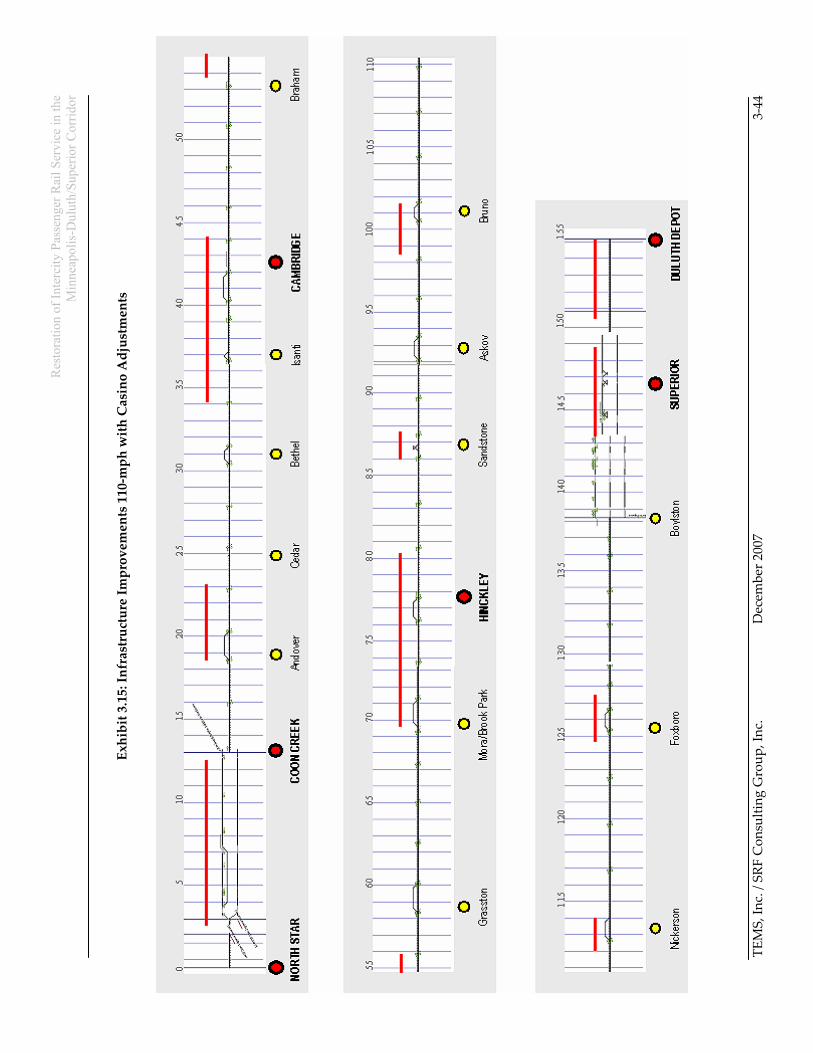
Exhibits 3.14 and 3.15 show the proposed capacity improvements that have been proposed for the basic 8-train 110-mph service, and for the enhanced operating plan that has been developed for the Casino rail link option. The casino rail link option reflects the reallocation of the Nickerson double tracking towards the south, where the Casino rail link would provide a northerly extension of the Hinckley-Brook Park siding; as well as the planned restoration of the Sandstone siding. Both of these changes are consistent with the revised operating plan that shifts more of the train operations towards the south end of the corridor, so the line capacity investment needs to follow.

Res
tora
tion
of In
terc
ity P
asse
nger
Rai
l Ser
vice
in th
e
Min
neap
olis
-Dul
uth/
Supe
rior C
orrid
or
TEM
S, In
c. /
SRF
Con
sulti
ng G
roup
, Inc
.
Dec
embe
r 200
7
3-
43
Ex
hibi
t 3.1
4: In
fras
truc
ture
Impr
ovem
ents
110
-mph
8 R
ound
Trip
s
Res
tora
tion
of In
terc
ity P
asse
nger
Rai
l Ser
vice
in th
e
Min
neap
olis
-Dul
uth/
Supe
rior C
orrid
or
TEM
S, In
c. /
SRF
Con
sulti
ng G
roup
, Inc
.
Dec
embe
r 200
7
3-
44
Exhi
bit 3
.15:
Infr
astr
uctu
re Im
prov
emen
ts 1
10-m
ph w
ith C
asin
o A
djus
tmen
ts