cardboard box crusher - scholar@uc
TRANSCRIPT

i
Cardboard Box Crusher
A Baccalaureate thesis submitted to the
Department of Mechanical and Materials Engineering College of Engineering and Applied Science
University of Cincinnati
in partial fulfillment of the requirements for the degree of
Bachelor of Science
in Mechanical Engineering Technology
by
Ato Kwamena Gaisie
April 2020
Thesis Advisor: Ahmed Elgafy, PhD

ii
TABLE OF CONTENTS
TABLE OF CONTENTS ........................................................................................................................... ii
LIST OF FIGURES ................................................................................................................................... iv
LIST OF TABLES ..................................................................................................................................... iv
ABSTRACT ................................................................................................................................................. v
PROBLEM DEFINITION AND RESEARCH ........................................................................................ 1
Problem Statement .................................................................................................................................. 1
Background ............................................................................................................................................. 1
RESEARCH ................................................................................................................................................ 2
Current State of the Art ........................................................................................................................ 2
Marathon Heavy-Duty Vertical Balers .......................................................................................... 2
The Extract Pack Aluminum Recycling Machine ......................................................................... 3
Mil-tek 2102 Cardboard and Plastic Baler .................................................................................... 3
End User .................................................................................................................................................. 4
Summary of Research ............................................................................................................................. 4
QUALITY FUNCTION DEVELOPMENT ............................................................................................. 5
Customer Features .................................................................................................................................. 5
Engineering Characteristics ................................................................................................................... 5
House of Quality ...................................................................................................................................... 6
Product Objectives .................................................................................................................................. 7
DESIGN ....................................................................................................................................................... 8
Concepts Drawings ................................................................................................................................. 8
MATERIAL AND COMPONENT SELECTION ................................................................................. 11
Finite Element Analysis ....................................................................................................................... 11
Pneumatic Cylinder Selection (Design/Safety Factor) ...................................................................... 13
Standards and Specifications ............................................................................................................... 14
FABRICATION AND ASSEMBLY........................................................................................................ 15
TESTING AND PROOF OF DESIGN ................................................................................................... 19
CURRENT STATE OF PROJECT......................................................................................................... 20
CONTINUOUS IMPROVEMENT ......................................................................................................... 21
PROJECT MANAGEMENT ................................................................................................................... 22
REFERENCES .......................................................................................................................................... 23

iii
APPENDIX A ............................................................................................................................................ 24
APPENDIX B ............................................................................................................................................ 25
APPENDIX C ............................................................................................................................................ 26
APPENDIX D ............................................................................................................................................ 24
APPENDIX E ............................................................................................................................................ 24
APPENDIX F ............................................................................................................................................ 28
APPENDIX G ............................................................................................................................................ 29
APPENDIX H ............................................................................................................................................ 30
APPENDIX I ............................................................................................................................................. 31
SPECIAL THANKS ................................................................................................................................. 32

iv
LIST OF FIGURES
• Figure 1: Marathon Heavy-Duty Vertical Baler
• Figure 2: Extract Pack Recycling Machine (Model No. BCB2003)
• Figure 3: Mil-tek 2102 Cardboard and Plastic Baler
• Figure 4: House of Quality for Cardboard Box Crusher
• Figure 5: Solidworks depiction of Concept 1
• Figure 6: Solidworks depiction of Concept 2
• Figure 7: Solidworks depiction of Concept 3
• Figure 8: Simulation showing stationary constraints
• Figure 9: Simulation depicting the plate and guide rod degrees of motion
• Figure 10: Results of simulation showing guide rod bearing stress factor
• Figure 11: Results of simulation showing guide rod and press plate connection stress
• Figure 12: Painted Box Crusher Components
• Figure 13: Press plate and piston rod fixture
• Figure 14: Painted guide rods/tubing
• Figure 16: Pneumatic cylinder face bolted
• Figure 17: Mounted Aluminum Extrusions
• Figure 18: Cardboard Box Crusher Assembled
• Figure 19: Plexi-Glass(Lexan) covering
• Figure 20: Air Pressure Booster
• Figure 21: Keyence Light Sensor
• Figure 22: Wiring Config. for Conveyor Motor
• Figure 23: Conveyor motor junction box
• Figure 24: Process before crushing
• Figure 25: Crushed box from a side orientation
• Figure 26: Side Profile of the Cardboard Box Crusher
• Figure 27: Front Profile of the Cardboard Box Crusher
• Figure 28: Parker K1 Air Cylinder
• Figure 29: SMC CDQ2B32 Air Cylinder
• Figure 30: SMC CDM2QF20 Air Cylinder
LIST OF TABLES
• Table 1: Initial Estimated Schedule
• Table 2: Budget for Cardboard Box Crusher

v
ABSTRACT
This is a Senior Design report on a Cardboard Box Crusher. This is a miniature model of
an industrial carboard baler machine. The Cardboard Box Crusher was manufactured to handle
smaller loads and quantities of boxes at a box by box basis. This machine is fully automated and
only requires human interaction when problems may arise or for maintenance purposes. The
report also includes initial concept designs as well as manufacturing processes that went into the
productions of the machine. Finally, this report is adjusted based on the stay home order issued
by the Governor of Ohio due to the COVID-19 outbreak.
Cardboard Box Crusher | Ato Kwamena Gaisie
1
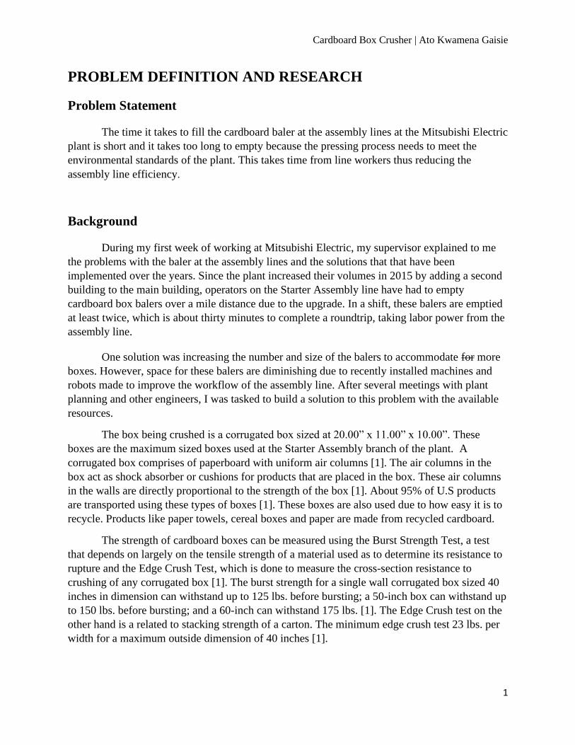
PROBLEM DEFINITION AND RESEARCH
Problem Statement
The time it takes to fill the cardboard baler at the assembly lines at the Mitsubishi Electric
plant is short and it takes too long to empty because the pressing process needs to meet the
environmental standards of the plant. This takes time from line workers thus reducing the
assembly line efficiency.
Background
During my first week of working at Mitsubishi Electric, my supervisor explained to me
the problems with the baler at the assembly lines and the solutions that that have been
implemented over the years. Since the plant increased their volumes in 2015 by adding a second
building to the main building, operators on the Starter Assembly line have had to empty
cardboard box balers over a mile distance due to the upgrade. In a shift, these balers are emptied
at least twice, which is about thirty minutes to complete a roundtrip, taking labor power from the
assembly line.
One solution was increasing the number and size of the balers to accommodate for more
boxes. However, space for these balers are diminishing due to recently installed machines and
robots made to improve the workflow of the assembly line. After several meetings with plant
planning and other engineers, I was tasked to build a solution to this problem with the available
resources.
The box being crushed is a corrugated box sized at 20.00” x 11.00” x 10.00”. These
boxes are the maximum sized boxes used at the Starter Assembly branch of the plant. A
corrugated box comprises of paperboard with uniform air columns [1]. The air columns in the
box act as shock absorber or cushions for products that are placed in the box. These air columns
in the walls are directly proportional to the strength of the box [1]. About 95% of U.S products
are transported using these types of boxes [1]. These boxes are also used due to how easy it is to
recycle. Products like paper towels, cereal boxes and paper are made from recycled cardboard.
The strength of cardboard boxes can be measured using the Burst Strength Test, a test
that depends on largely on the tensile strength of a material used as to determine its resistance to
rupture and the Edge Crush Test, which is done to measure the cross-section resistance to
crushing of any corrugated box [1]. The burst strength for a single wall corrugated box sized 40
inches in dimension can withstand up to 125 lbs. before bursting; a 50-inch box can withstand up
to 150 lbs. before bursting; and a 60-inch can withstand 175 lbs. [1]. The Edge Crush test on the
other hand is a related to stacking strength of a carton. The minimum edge crush test 23 lbs. per
width for a maximum outside dimension of 40 inches [1].

Cardboard Box Crusher | Ato Kwamena Gaisie
2
RESEARCH
Current State of the Art
Marathon Heavy-Duty Vertical Balers
This baler manufactured by Marathon is their flagship model with their most innovative
technology in order to crush boxes of different shapes and sizes. Due their standard controls and
panel box, the user experiences an ease of use that can be associated with that of smaller baler.
This baler exerts a maximum pressure of 2500 psi and a max force of 70,690 lbs. [2]. They also
boast features such as fixed retainer teeth on the door and back of the baler to reduce material
spring back as well as a programmable smart relay to fit the operation style of the customer [2].
Marathon Heavy-Duty Vertical Balers also have optional upgrades to bring a variety of options
to the user such as bale auto-eject and wire guides for tying up the bales after the compacting
process [2].
The initial investment for a Marathon Heavy-Duty Vertical Baler is very high and
requires a dedicated space for installation. Due to its size and immobility, it will not be a suitable
solution for the problem at hand.
Figure 1: Marathon Heavy-Duty Vertical Baler

Cardboard Box Crusher | Ato Kwamena Gaisie
3
The Extract Pack Aluminum Recycling Machine
This is the very first baler that both bales and extracts the liquid from waste beverage
containers. Harmony Enterprise Inc., the company that manufacturers the Extract Pack, claims
that their baler performs 7 times better than manually draining the container [3]. Due to the
liquid draining process, this baler guarantees complete closure of the doors during the process in
order to avoid messy flows around the baler. The baler also has “shark teeth”, which are sharp
prongs that are lined on the chamber floor and ram face to better extract the liquid [3].
The cost of the Extract Pack Aluminum Recycling Machine is very high. The liquid
draining properties are nice to have but are not a necessity for the problem at hand.
Figure 2: Extract Pack Recycling Machine (Model No. BCB2003)
Mil-tek 2102 Cardboard and Plastic Baler
The Mil-tek 2102 is a small compact baler that is suitable for small businesses with a
regular flow of carboard usage. It has the ability to bale not only carboard but plastics and other
materials. Due to its size, it has a low energy rating and also less noise during the baling
operation [4]. It has a maximum pressure of 116 psi and a maximum force of 4960 lbs. [4].
The Mil-tek 2102 Cardboard and Plastic baler is the closest ready-to-buy solution
available on the market. The cost for a single unit is fairly affordable for the short-term solution
but due to Mitsubishi Electric’s long-term goal of incorporating the solution to different parts of
the plant, a total cost of purchasing multiple units to be placed at vantage points will be about the
available budget set for the solution.

Cardboard Box Crusher | Ato Kwamena Gaisie
4
Figure 3: Mil-tek 2102 Cardboard and Plastic Baler
End User
The primary user for the cardboard box crusher is the assembly line operator. The
operator at Mitsubishi Electric Automotive America is tasked with packing parts in and out of
their packaging as well as man manual add stations on the assembly line for parts that cannot be
assembled by a robot or machine. The operator will have the task of supplying the cardboard box
crusher with an empty cardboard box.
The secondary user for the cardboard box crusher is the line technician or engineer. In
case of improvements and adjustments that need to be made to the cardboard box crusher, the
line technician or engineer will have to bypass security and safety locks that protect the box
crusher in order to make said changes.
Summary of Research
In conclusion, the ideal solution to the problem does not exist for purchasing purposes
and using this research as a basis, a close to ideal solution can be built and in later years can be
modified and improved upon to fit different problematic scenarios. An ideal solution will need to
be able to bolt temporarily to the conveyor being used. It also needs to be stable enough to
withstand repeated pressing force without significant deformity to the machine or conveyor.

Cardboard Box Crusher | Ato Kwamena Gaisie
5
QUALITY FUNCTION DEVELOPMENT
Customer Features
• Safety
• Power Consumption
• Ease of Use
• Smart (Responsive to GOT inputs)
• Noise Factor
• Design/Form Factor
• Initial Investment Cost
Engineering Characteristics
• Base Material Selection
• Joining/Fasteners
• Pneumatic Cylinder Selection
• Load Distribution per Design
• Crushing Force and Pressure
• Graphical User Interface Selection

Cardboard Box Crusher | Ato Kwamena Gaisie
6
House of Quality
Figure 4: House of Quality for Cardboard Box Crusher

Cardboard Box Crusher | Ato Kwamena Gaisie
7
Product Objectives
Safety (25%)
To ensure safety of employees that work closely to the machine, light curtains will be
installed at all entry and exit points of the machine. This may include an interlock system for the
door to access the machine.
Power Consumption (3.6%)
This feature has to do with selecting the right motor for the belt conveyor to be used.
Ease of Use (17.9%)
The machine should be constructed with material and components that are familiar to the
technicians and engineers in any case that I am not able to solve issue that may arise in the
future.
Smart (Responsive to GOT inputs) (14.3%)
The outline of the GOT (Graphical user interface manufactured by Mitsubishi) should be
well laid out and should function as designed or labeled.
Noise Factor (21.4%)
A muffler will be installed on the air pressure amplifier to reduce noise when the machine
is operational.
Design/Form Factor (7.1%)
It should be able to take up the limited amount of space on offer to engineering by the
Mitsubishi plant planning team.
Initial Investment Cost (10.7%)
Most components such as plexi-glass and aluminum extrusions will be repurposed from
machines that are no longer on use or discarded.

Cardboard Box Crusher | Ato Kwamena Gaisie
8
DESIGN
Concepts Drawings
Figure 5: Solidworks depiction of Concept 1
Concept 1
In this concept, an attachment base will be manufactured with fins to serve as structural
support. This base will be mounted on one side of the conveyor to be used. A metallic tube will
be used as the main load point holding all the other features upright. The pneumatic cylinder will
be face mounted beneath the top plate as will as oil bearings that are attached to the sides. The
bearing will serve as a holding place that allows the guide rods to move up and down. The
cylinder and guide rods will be threaded on the ends that attach to the press plate.
This concept is inexpensive and simple to manufacture. The drawbacks to this design is
the imbalance of the press plate that may cause deformity of increased tension in the fasteners of
the tube.

Cardboard Box Crusher | Ato Kwamena Gaisie
9
Figure 6: Solidworks depiction of Concept 2
Concept 2 (Final Design)
This concept utilizes two channel extrusions that are cut to size and bolted to each side of
the conveyor. Each side will also have a welded to the channel a metallic tube, smaller than that
of concept 1. To reduce material cost the top plate will have a t-cutout and the cylinder will be
mounted on the piston side to the top plate. The guide rods and bearings from concept 1 will also
be used.
This concept is a little more expensive than that of the previous one but due to the double
tower system, the stress on fasteners and tubes will be lessened.

Cardboard Box Crusher | Ato Kwamena Gaisie
10
Figure 7: Solidworks depiction of Concept 3
Concept 3
In this concept, the double tower designed is used. The bottom plate will be mounted on
top of the conveyor and underneath that moving belt. The tubes will be then mounted on each
side of the plate overhung. The cylinder is mounted beneath the top plate like in concept 1 and
the guide rods and bearings will also follow the same principle as concept 1.
The bottom plate will be used to reinforce the bed of the conveyor where the crushing
will occur. This design implementation is very expensive due to the amount and type of material
being used. The bottom plate might also experience a significant amount of stress from the tower
ends.

Cardboard Box Crusher | Ato Kwamena Gaisie
11
MATERIAL AND COMPONENT SELECTION
Per Mitsubishi requirements, the materials and component brands to be used for the machine
were as follows;
• A36 Plates/Bar Stock/Round Bar
• A500 GRB Tubing
• SMC Air Solutions
• Keyence Sensors and Light Curtains
• Mitsubishi PLC Products (CPU, Input/output cards, Graphical User Interfaces)
• Lexan Sheets for Machine Protection
• Aluminum Extrusions (80/20) for Machine Protection
Finite Element Analysis
Solidworks was used to determine pressure points as well as stress factors that needed to
be watched for based on the final chosen design. All non-moving parts are constrained, and the
guide rods and plate are allowed only the reasonable degrees and directions of freedom. It was
then run through a simulation of repeated motion for a given period of time of 360 hours (
Estimated time for crushing over a three-year duration).
Figure 8: Simulation showing stationary constraints
Cardboard Box Crusher | Ato Kwamena Gaisie
12
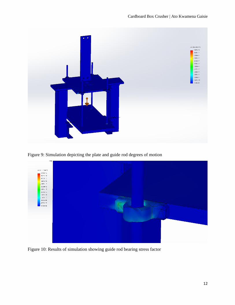
Figure 9: Simulation depicting the plate and guide rod degrees of motion
Figure 10: Results of simulation showing guide rod bearing stress factor

Cardboard Box Crusher | Ato Kwamena Gaisie
13
Figure 11: Results of simulation showing guide rod and press plate connection stress
After the simulation was run, there were two major points to consider before manufacturing. The
first point of concern was the guide rod bearings as seen in Figure 10. The bearings were
changed to better hold the guide rods for a longer time period. The second concern was the stress
point between the guide rods and plate. To ease this stress the thread pitch was increases to
increase the holding strength of the guide rods.
Pneumatic Cylinder Selection (Design/Safety Factor)
The pneumatic cylinder is the major force generating component of the machine and thus
the design and safety factor was built around it. The values and equations used are based on the
manufacturer’s published work.
Minimum Force Needed to Crush Box

Cardboard Box Crusher | Ato Kwamena Gaisie
14
BCT = Box Compression Test
ECT = Edge Crush Test
Pneumatic Cylinder Selection
Checking Final Safety factor after Cylinder Section
Standards and Specifications
• American Society of Testing and Materials (ASTM) for all materials.
• All welding will be done according to the American Welding Society (AWS) and the
American Society of Mechanical Engineers (ASME) specifications.
• Every metallic structure must be deburred and painted Mits-blue before being installed on
the plant floor.
Cardboard Box Crusher | Ato Kwamena Gaisie
15
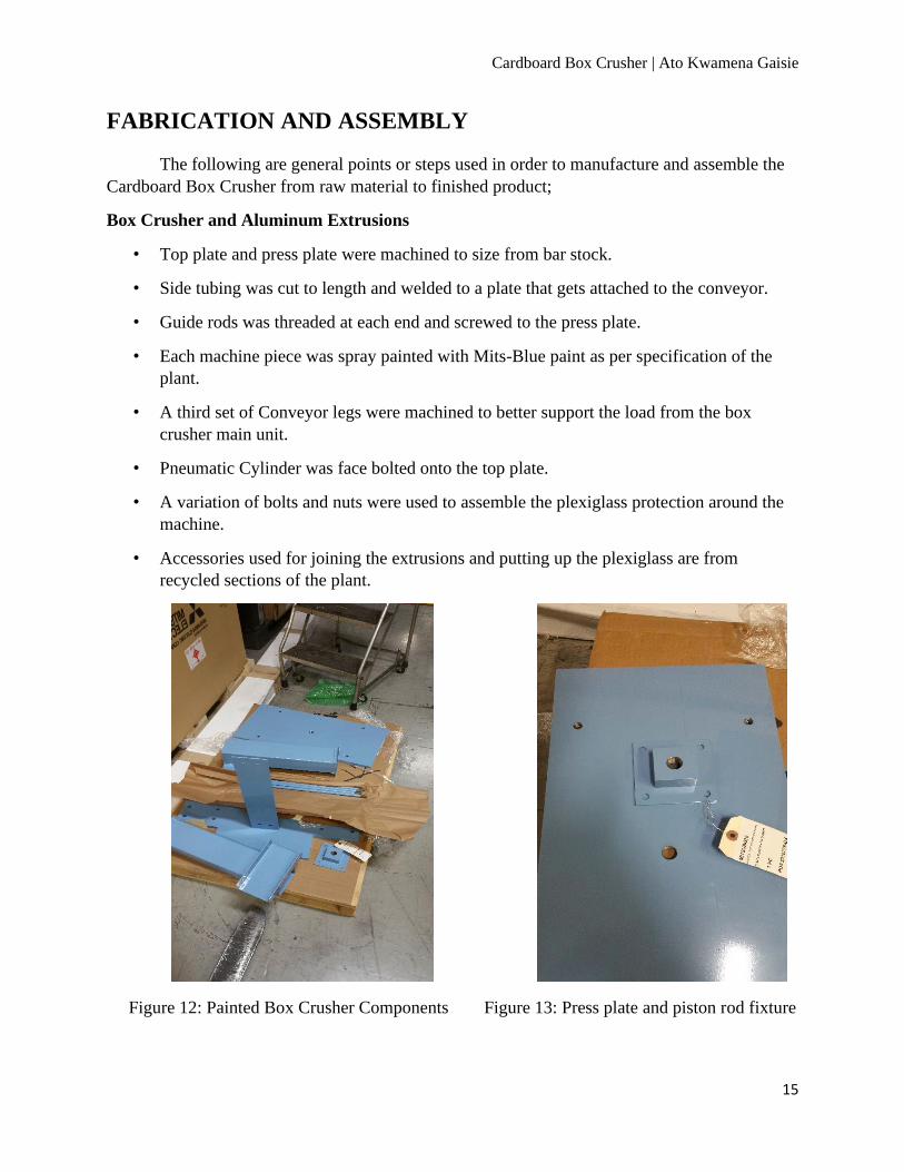
FABRICATION AND ASSEMBLY
The following are general points or steps used in order to manufacture and assemble the
Cardboard Box Crusher from raw material to finished product;
Box Crusher and Aluminum Extrusions
• Top plate and press plate were machined to size from bar stock.
• Side tubing was cut to length and welded to a plate that gets attached to the conveyor.
• Guide rods was threaded at each end and screwed to the press plate.
• Each machine piece was spray painted with Mits-Blue paint as per specification of the
plant.
• A third set of Conveyor legs were machined to better support the load from the box
crusher main unit.
• Pneumatic Cylinder was face bolted onto the top plate.
• A variation of bolts and nuts were used to assemble the plexiglass protection around the
machine.
• Accessories used for joining the extrusions and putting up the plexiglass are from
recycled sections of the plant.
Figure 12: Painted Box Crusher Components Figure 13: Press plate and piston rod fixture

Cardboard Box Crusher | Ato Kwamena Gaisie
16
Figure 14: Painted guide rods/tubing Figure 15: GoT Enclosure
Figure 16: Pneumatic cylinder face bolted Figure 17: Mounted Aluminum Extrusions

Cardboard Box Crusher | Ato Kwamena Gaisie
17
Figure 18: Cardboard Box Crusher Assembled Figure 19: Plexi-Glass(Lexan) covering
Air Pipes and Electric Wiring
• Based on the manuals for each automation equipment, the machine wiring was
completed.
• The factory uses an NPN connection throughout the plant and thus was used to connect
most of the light curtain components.
• All wires are run from the machine to the inverter and then finally into the electric
junction box.
• CC-Link cables are used to connect all the PLC components to increase response speed.
• The sensors run directly to the PLC in the junction box.
• An air pressure booster was also wired to the cylinder air input to improve the crushing
pressure.

Cardboard Box Crusher | Ato Kwamena Gaisie
18
Figure 20: Air Pressure Booster Figure 21: Keyence Light Sensor
Figure 22: Wiring Config. for Conveyor Motor Figure 23: Conveyor motor junction box

Cardboard Box Crusher | Ato Kwamena Gaisie
19
TESTING AND PROOF OF DESIGN
At each milestone point within the project, a trial was run with empty cardboard boxes to
access progress and correct mistakes. A force/pressure gauge was used to test that the pneumatic
cylinder is performing correctly and that the press plate is actual delivering the required amount
of force to crush the boxes. A set of 10 boxes were tested for the first wiring configuration so far.
Subsequent testing was not done due to the Governor’s lockdown order. Due to this situation,
there are no comparative values to determine best measure to take for automation going forward.
Figure 24: Process before crushing Figure 25: Crushed box from a side orientation

Cardboard Box Crusher | Ato Kwamena Gaisie
20
CURRENT STATE OF PROJECT
The following figures depict the state with which the project was left in after the stay
home order by the Governor of Ohio was put into effect.
Figure 26: Side Profile of the Cardboard Box Crusher
Figure 27: Front Profile of the Cardboard Box Crusher

Cardboard Box Crusher | Ato Kwamena Gaisie
21
CONTINUOUS IMPROVEMENT
Based on the fact that the Cardboard Box Crusher, if effective, will be replicated
throughout other assembly lines in the plant, future improvements are necessary . From the
results of current tests, the box crushes about 85% of the time which is a good running
percentage but to increase the efficiency and reduce machinist interactions. I have researched
implementing smaller pneumatic cylinders to the sides of the conveyor that presses the box
(Indenting it) and guaranteeing a better crushing rate. These implementations are inexpensive
and will yield efficiencies closer to 95% approximately.
Figure 28: Parker K1 Air Cylinder Figure 29: SMC CDQ2B32 Air Cylinder
Figure 30: SMC CDM2QF20 Air Cylinder

Cardboard Box Crusher | Ato Kwamena Gaisie
22
PROJECT MANAGEMENT
Project Budget Limit
After a meeting with my supervisor and plant manager, a budget of $4000, excluding
parts that can be found at the plant, was set in order to build the Cardboard Box Crusher.
Key Milestones (Initial Estimates)
Fortunately, majority of the project was scheduled before the stay home order was put
into effect and therefore, the machine is currently sitting in the ‘Program PLC and GOT for Box
Crusher/ Implementation of sensors’ stage.
Table 1: Initial Estimated Schedule
Full Budget (So Far)
Table 2: Budget for Cardboard Box Crusher
Dates Milestones Completed
10/29/2019 Re-Design conveyor rails
11/26/2019 Testing crushed boxes flow process
12/17/2019 Re-Construct Plexi glass protection around box crusher
1/28/2020 Install and Configure Safety Features i.e. Light Curtains
2/25/2020 Program PLC and GOT for box crusher/ Implimention of Sensors
3/31/2020 Create all documentation for operators and general public
4/9/2020 Tech Expo Day

Cardboard Box Crusher | Ato Kwamena Gaisie
23
REFERENCES
1. Apple Limited. Corrugated Boxes. [Online] Apple Limited, 2008. [Cited: September 2, 2019.]
https://www.appleltd.com/corrugated-box-specifications.aspx.
2. Ramjet. Heavy Duty Industrial Balers. North Carlifornia Compactors. [Online] Environmental Solutions
Group, 2011. [Cited: September 2, 2019.] https://www.norcalcompactors.net/wp-
content/uploads/pdfs/VerticalBaler-2011-NCCI.pdf.
3. Harmony Enterprises. ExtractPack Vertical Liquid Extraction Baler. Harmony Enterprises. [Online]
2019. [Cited: September 2, 2019.] https://harmony1.com/harmony-products/extract-pack-vertical-
liquid-extraction-baler/.
4. Mil-tek. 2102 Cardboard & Plastic Baler. Miltek USA. [Online] 2014. [Cited: September 4, 2019.]
https://www.miltekusa.com/product/2102-cardboard-plastic-baler.

Cardboard Box Crusher | Ato Kwamena Gaisie
24
APPENDIX A
Based on a survey conducted on the 17th of September 27, 2019 at Mitsubishi Electric, by
line workers on the Starter Assembly line, concerns such as ease of use, safety and Noise were
raised and based on thirty completed surveys of which as sample has been attached below, clear
product objectives were devised.
Survey Sample
Cardboard Press Machine
Hi, my name is Ato Gaisie, a co-op student on the starter side of the plant working under Dennis
Dickerson. I have been tasked to build a machine on the empty conveyor by the performance testers
that will crush cardboard boxes after they have been emptied. Please answer the following survey
questions to help guide this project to completion.
Answer 1 to 5 in order of importance; 1 meaning least important and 5 meaning highest importance
How is important is each feature to you?
Safety (5) Power Consumption (4) Ease of Use (5) Smart (Responsive to GOT inputs) (3) Noise Factor (5) Design (4) Initial Investment Cost (4)
Answer 1 to 5 in order of satisfaction; 1 meaning least satisfied and 5 meaning highest satisfaction
How satisfied are you with the current baler system?
Safety (4) Power Consumption (1) Ease of Use (3) Smart (Responsive to GOT inputs) (2) Noise Factor (4) Design (5) Initial Investment Cost (4)
How much will you be willing to pay for my custom build?
$1000, $2000, $3000+ ($1000)

Cardboard Box Crusher | Ato Kwamena Gaisie
25
APPENDIX B
House of Quality

Cardboard Box Crusher | Ato Kwamena Gaisie
26
APPENDIX C
Corrugated Box values

Cardboard Box Crusher | Ato Kwamena Gaisie
27
APPENDIX D
APPENDIX E
CC-Link cable connection diagram

Cardboard Box Crusher | Ato Kwamena Gaisie
28
APPENDIX F
Conveyor inverter connection diagram

Cardboard Box Crusher | Ato Kwamena Gaisie
29
APPENDIX G
Light Curtain wiring configuration

Cardboard Box Crusher | Ato Kwamena Gaisie
30
APPENDIX H
Conveyor motor wiring configuration

Cardboard Box Crusher | Ato Kwamena Gaisie
31
APPENDIX I
PLC Junction Box used for Cardboard Box Crusher

Cardboard Box Crusher | Ato Kwamena Gaisie
32
SPECIAL THANKS
Mitsubishi Electric – Sponsor
Dennis Dickerson – Co-op Supervisor
Ahmed Elgafy, PhD – Senior Design Advisor
Anthony Inderhees – Design Help and Automation Advisor