carolina power & light company attn: mr. james scarola …€¦ · · 2004-06-03carolina...
TRANSCRIPT

May 25, 2004Carolina Power & Light CompanyATTN: Mr. James Scarola
Vice President - Harris PlantShearon Harris Nuclear Power PlantP. O. Box 165, Mail Code: Zone 1New Hill, NC 27562-0165
SUBJECT: SHEARON HARRIS NUCLEAR POWER PLANT - NRC PLANT DESIGN -PILOT INSPECTION REPORT NO. 05000400/2004007
Dear Mr. Scarola:
On April 16, 2004, the Nuclear Regulatory Commission (NRC) completed a pilot, plant designinspection at your Shearon Harris reactor facility. The enclosed report documents theinspection findings which were discussed on April 16, 2004, with you and other members ofyour staff.
This inspection was an examination of activities conducted under your license as they relate tosafety and compliance with the Commission’s rules and regulations, and with the conditions ofyour operating license. Within these areas, the inspection involved selected examination ofprocedures and representative records, observations of activities, and interviews withpersonnel.
Based on the results of the inspection, no findings of significance were identified.
In accordance with 10 CFR 2.390 of the NRC's "Rules of Practice," a copy of this letter and itsenclosure will be available electronically for public inspection in the NRC Public DocumentRoom or from the Publicly Available Records (PARS) component of NRC's document system(ADAMS). ADAMS is accessible from the NRC Web site at http://www.nrc.gov/reading-rm/adams.html (the Public Electronic Reading Room).
Sincerely,
/RA/
Charles R. Ogle, ChiefEngineering Branch 1Division of Reactor Safety
Docket No.: 50-400License No.: NPF-63
Enclosure: (See page 2)

CP&L 2
Enclosure: NRC Inspection Report No. 05000400/2004007w/Attachment: Supplemental Information
cc w/encl:James W. Holt, ManagerPerformance Evaluation and Regulatory Affairs CPB 9Carolina Power & Light CompanyElectronic Mail Distribution
Robert J. Duncan IIDirector of Site OperationsCarolina Power & Light CompanyShearon Harris Nuclear Power PlantElectronic Mail Distribution
Benjamin C. WaldrepPlant General Manager--Harris PlantCarolina Power & Light CompanyShearon Harris Nuclear Power PlantElectronic Mail Distribution
Terry C. Morton, ManagerSupport ServicesCarolina Power & Light CompanyShearon Harris Nuclear Power PlantElectronic Mail Distribution
John R. Caves, SupervisorLicensing/Regulatory ProgramsCarolina Power & Light CompanyShearon Harris Nuclear Power PlantElectronic Mail Distribution
Steven R. CarrAssociate General Counsel - Legal DepartmentProgress Energy Service Company, LLCElectronic Mail Distribution
John H. O’Neill, Jr.Shaw, Pittman, Potts & Trowbridge2300 N. Street, NWWashington, DC 20037-1128
(cc w/encl cont’d - See page 3)

CP&L 3
(cc w/encl cont’d)Beverly Hall, Acting DirectorDivision of Radiation ProtectionN. C. Department of Environmental Commerce & Natural ResourcesElectronic Mail Distribution
Peggy ForceAssistant Attorney GeneralState of North CarolinaElectronic Mail Distribution
Public Service CommissionState of South CarolinaP. O. Box 11649Columbia, SC 29211
Chairman of the North Carolina Utilities Commissionc/o Sam Watson, Staff AttorneyElectronic Mail Distribution
Robert P. GruberExecutive DirectorPublic Staff NCUC4326 Mail Service CenterRaleigh, NC 27699-4326
Herb Council, ChairBoard of County Commissioners of Wake CountyP. O. Box 550Raleigh, NC 27602
Tommy Emerson, ChairBoard of County Commissioners of Chatham CountyElectronic Mail Distribution
Distribution: (See page 4)

CP&L 4
Distribution w/encl:C. Patel, NRRL. Slack, RII EICSRIDSNRRDIPMLIPBPUBLIC
OFFICE RII:DRS RII:DRS RII:DRS RII:DRS RII:DRS RII:DRS RII:DRP
SIGNATURE RA RA RA RA RA RA RA
NAME NMerriweather RCortes KVanDoorn MScott SRudisail GHopper JMoorman
DATE 5/21/2004 5/18/2004 5/18/2004 5/18/2004 5/20/2004 5/19/2004 5/25/2004
E-MAIL COPY? YES NO YES NO YES NO YES NO YES NO YES NO YES NO
PUBLIC DOCUMENT YES NO
OFFICE RII:DRP
SIGNATURE RA
NAME PFredrickson
DATE 5/25/2004 6/ /2004 6/ /2004 6/ /2004 6/ /2004 6/ /2004 6/ /2004
E-MAIL COPY? YES NO YES NO YES NO YES NO YES NO YES NO YES NO
PUBLIC DOCUMENT YES NO
OFFICIAL RECORD COPY DOCUMENT NAME: C:\ORPCheckout\FileNET\ML041540256.wpd
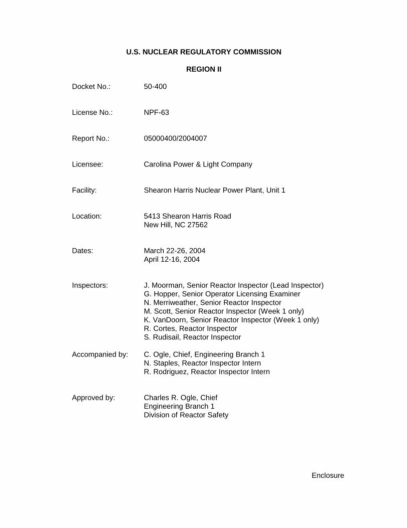
Enclosure
U.S. NUCLEAR REGULATORY COMMISSION
REGION II
Docket No.: 50-400
License No.: NPF-63
Report No.: 05000400/2004007
Licensee: Carolina Power & Light Company
Facility: Shearon Harris Nuclear Power Plant, Unit 1
Location: 5413 Shearon Harris RoadNew Hill, NC 27562
Dates: March 22-26, 2004April 12-16, 2004
Inspectors: J. Moorman, Senior Reactor Inspector (Lead Inspector)G. Hopper, Senior Operator Licensing ExaminerN. Merriweather, Senior Reactor InspectorM. Scott, Senior Reactor Inspector (Week 1 only)K. VanDoorn, Senior Reactor Inspector (Week 1 only) R. Cortes, Reactor InspectorS. Rudisail, Reactor Inspector
Accompanied by: C. Ogle, Chief, Engineering Branch 1N. Staples, Reactor Inspector InternR. Rodriguez, Reactor Inspector Intern
Approved by: Charles R. Ogle, ChiefEngineering Branch 1Division of Reactor Safety

Enclosure
SUMMARY OF FINDINGS
IR 05000400/2004007; 03/22-26/2004 and 04/12-16/2004; Shearon Harris Nuclear PowerPlant, Unit 1; Plant Design - Pilot, Enclosures 1, 2, and 3.
This inspection was conducted by a team of regional inspectors. No findings of significancewere identified. The NRC’s program for overseeing the safe operation of commercial nuclearpower reactors is described in NUREG-1649, “Reactor Oversight Process,” Revision 3, datedJuly 2000.
A. NRC-Identified and Self-Revealing Findings
No findings of significance were identified.
B. Licensee-Identified Violations
None.

Enclosure
REPORT DETAILS
1. REACTOR SAFETY
Cornerstones: Initiating Events, Mitigating Systems and Barrier Integrity
1R.DS Plant Design - Pilot (71111.DS)
1R.DS1 Safety System Design and Performance Capability (71111.DS, Enclosure 1)
This team inspection reviewed selected components and operator actions that would beused to prevent or mitigate the consequences of a steam generator tube rupture(SGTR) event. Components in the main steam (MS) system, auxiliary feedwater (AFW)system, steam generator (SG) blowdown system, chemical and volume control system(CVCS), reactor coolant system (RCS), safety injection (SI) system, and radiationmonitoring system were included. This inspection also examined supporting equipment,equipment which provides power to these components, and the associatedinstrumentation and controls. The SGTR event is a risk-significant event as determinedby the licensee’s probabilistic risk assessment.
.1 System Needs
.11 Process Medium
a. Inspection Scope
The team reviewed the AFW and high head safety injection (HHSI) net positive suctionhead and water source calculations, operating/lineup procedures, drawings, licensingand design basis information, surveillance procedures, and vendor manuals. Thereview included the ability of the steam generator power operated relief valves (PORVs)to support RCS cooldown, and the ability of the HHSI pumps to provide cooling of theRCS. The review also included the refueling water storage tank (RWST) with emphasison post-accident make-up capability, the condensate storage tank (CST), includingminimum-flow flowpaths for AFW and HHSI pumps and vortexing considerations. Theteam also conducted field walkdowns of the systems in the plant to verify that systemdesign, Technical Specifications (TS), and Updated Final Safety Analysis Report(UFSAR) assumptions were consistent with the actual capability of systems andequipment required to mitigate an SGTR event.
b. Findings
No findings of significance were identified.

2
Enclosure
.12 Energy Sources
a. Inspection Scope
The team walked down the energy sources of selected components to verify thatselected portions of the systems alignment were consistent with the design basisassumptions, performance requirements, and system operating procedures. The teamreviewed valve lineup procedures for the steam supply to the turbine-driven AFW pumpand the sources of air for air operated valves (AOVs) such as the pressurizer PORVs. The team also reviewed the testing and maintenance history for these AOVs to assessthe reliability and availability of alternate air sources.
The team reviewed voltage drop calculations for a sample of safety-related loads suchas motors, valve operators, inverters, and radiation monitors to verify that adequatevoltage would be available at the end device during worst case minimum grid operatingvoltage conditions. The team also reviewed surveillance records on breaker alignmentchecks and bus voltage readings to verify that these checks were being performed inaccordance with the requirements specified in the TS. The calculations reviewed arelisted in the Attachment. The specific components reviewed are listed below:
• AFW pump motors• SI pump motors• Vital Inverters• 125 volts direct current (VDC) batteries• Battery chargers• 6.9 Kilo-Volt (kV) switchgear
b. Findings
No findings of significance were identified.
.13 Instrumentation and Controls
a. Inspection Scope
The team examined, on a sample basis, instrumentation and indication that are used byoperators for detection of primary to secondary leakage and an SGTR event, as well asselected control circuits used for SGTR event mitigation. Instrumentation identified for detection of an SGTR event included the main steam line radiation monitors (on each of3 main steam lines), liquid radiation monitor assembly (i.e., steam generator blowdown),condensor vacuum pump effluent treatment system radiation monitor, and SG narrowrange level instruments. Instruments and indications used by operators for mitigation ofthe event included condensate storage tank level, refueling water storage tank level,and SG narrow range level. For these instruments, the team reviewed the SGTRaccident analysis, instrument loop drawings, scaling calculations, surveillance calibrationtest procedures, annunciator response procedures, and other design documents

3
Enclosure
establishing the basis for calibration and alarm setpoints, to confirm that the calibration,setpoints, and emergency operating procedures were consistent with the design andlicensing basis.
For controls used in SGTR mitigation, the team reviewed various electrical drawings ofthe control circuits for the steam generator PORVs, the pressurizer PORVs, auxiliaryfeedwater flow control valves, and the automatic initiation and shutdown controls(including low suction pressure trip instrumentation) for the motor driven and turbinedriven auxiliary feedwater pumps to confirm that the control circuits implemented thefunctional logic requirements described by the design basis documents.
b. Findings
No findings of significance were identified.
.14 Operator Actions
a. Inspection Scope
The team reviewed plant operating procedures (OPs), emergency operating procedures(EOPs), abnormal operating procedures (APs), and annunciator response proceduresthat would be used in the identification and mitigation of an SGTR event. Specificprocedures reviewed are included in the Attachment to this report.
The review was done to verify that the procedures were consistent with the UFSARdescription of an SGTR event and with the Westinghouse Owners Group EmergencyResponse Guidelines, including the periodic updates. In addition, the team comparedthe procedural requirements against the EPRI guidelines requiring early action for plantshutdown after leak detection. The team reviewed step deviation justifications andcompared each step against the requirements of Procedure OMM-006, “EmergencyOperating Procedure Writer’s Guide” to verify that procedures were written clearly andunambiguously. The team conducted discussions with licensed operators and reviewedjob performance measures and training documents pertaining to an SGTR event toensure that training was consistent with the procedures.
In addition, the team observed a simulation of an SGTR event on the plant simulator toverify that operator training, procedural guidance, and instrumentation were adequate toidentify an SGTR event and implement post-event mitigation strategies. The operatoraction times for performance of SGTR event mitigation activities were observed andcompared against those stated in the UFSAR accident analyses for steam generatoroverfill.
The team also conducted plant walkdown inspections for selected local operator actionsto verify that the installed configuration and system alignments were consistent withdesign basis assumptions and procedural guidance. These actions included localmanual isolation of a stuck open atmospheric dump valve, refilling the reactor water

4
Enclosure
storage tank with borated water, local operation of an atmospheric dump valve, andauxiliary feedwater lineup.
b. Findings
No findings of significance were identified.
.15 Heat Removal
a. Inspection Scope
The team reviewed design calculations, drawings, and surveillance and test proceduresfor selected equipment to assess the reliability and availability of equipment used toprovide cooling for the HHSI pumps and AFW pumps. The team conducted fieldwalkdowns of the equipment to verify that operating conditions were consistent withdesign assumptions. The equipment reviewed was reviewed to verify that there wasadequate cooling for these pumps at both full and minimum flow conditions. The teamalso verified design calculations, machinery history, and heat transfer removal capabilityfor the HHSI pump room air handling units to ensure adequate room cooling duringdesign basis events.
b. Findings
No findings of significance were identified.
.2 System Condition and Capability
.21 Installed Configuration
a. Inspection Scope
The team performed field walkdowns of selected components in the HHSI, AFW, MS,service water and emergency service water (ESW) systems to assess observablematerial condition and the installed configuration of components. This review was alsoconducted to verify that selected valves and components in these systems were in theirrequired position and that the configuration was consistent with design drawings. Theteam reviewed action requests on foreign material exclusion and on the CST bladderwith emphasis on possible bladder material deterioration and other failure mechanismsthat could lead to obstruction the AFW pump suction.
The team reviewed design drawings and walked down the accessible portions of themain steam line monitors, the liquid radiation monitor assembly (SG blowdown), and thecondenser vacuum pump effluent treatment system radiation monitor, to confirm that theinstrument configurations were installed consistent with the plant design. The teamspecifically sought to verify that the radiation detector locations, power supplies, as wellas, control room indicators, annunciators, and setpoints, were consistent with design

5
Enclosure
drawings and the UFSAR description of the radiation monitor channels. The teamperformed field walkdowns and/or reviewed the design drawings to verify that the tapsfor the RWST and CST level instruments were located so as to preclude adversevelocity effects on the process measurement. In addition, the team visually inspectedthe routing of the tubing and measured the installed elevations of the CST level andAFW suction pressure transmitters to verify that the instruments were located consistentwith design drawings as well as scaling and setpoint calculations.
The team also performed field inspections of portions of the Class 1E electricaldistribution system; including the 6900 volts alternating current (VAC) switchgear, 480VAC load centers, 480 VAC motor control centers, and 125 VDC batteries, chargers,and panels. The purpose of the inspections was to assess general material condition,verify that system alignments were consistent with design and licensing basisassumptions, and to identify degraded conditions of SGTR mitigation equipment.
b. Findings
No findings of significance were identified.
.22 Operation
a. Inspection Scope
The team performed field walkdowns of selected components specified in the SGTREOP for which local operation or main control room operation was required to verify thatoperators could adequately determine component status and that the components couldbe operated under conditions that would exist during an SGTR event. Thesecomponents included the turbine driven AFW steam supply motor operated valve(MOV), and the SG PORVs. Another aspect that was reviewed was post-accidentRWST make-up capability using the CVCS. The team reviewed machinery history andperformed field walkdowns of the boric acid transfer pumps, the make-up water pumpsand selected valves located between the boric acid tank and reactor makeup waterstorage tank to the RWST to verify that operators could adequately operate the systemduring an SGTR event.
b. Findings
No findings of significance were identified.

6
Enclosure
.23 Design
a. Inspection Scope
Mechanical Design
The team reviewed vendor manuals for the HHSI and AFW pumps, vendor manuals forselected flow control valves, the UFSAR, and the TS to verify that vendorrecommendations and licensing basis requirements had been appropriately translatedinto design calculations and surveillance requirements. The team also reviewed thedesign of the AFW flow control valves and minimum-flow lines to determine if operatingexperience items were applicable to this design. In addition, net positive suction headcalculations and head curve data for both the AFW and HHSI pumps were reviewed toverify that adequate water levels were available in the CST and RWST. Vortexingconsiderations were also reviewed.
The team reviewed records of preventive maintenance and performed field walkdownsof selected components in the HHSI, CVCS, ESW, MS, and AFW systems to verify thatthese activities were maintaining the assumptions of the licensing and design bases. During these reviews, the team focused on potential common mode failurevulnerabilities that could be introduced by design or maintenance activities.
Instrumentation and Controls Design
The team reviewed instrument detail drawings showing installed transmitter and sensingline elevations, process instrumentation control scaling calculations, and level setpointcalculations of the CST, RWST, AFW suction pressure instrument channels todetermine if the setpoints for the level alarms and interlocks (e.g., high, low, low-low,and empty RWST tank levels) were correctly established to meet technicalspecifications and the design performance requirements of the system. In addition, thesurveillance and calibration test procedures and test records were reviewed for theabove instruments to verify that they specified setpoints consistent with the results of thesetpoint calculations or applicable scaling documents. The team also reviewed asample of replacement part evaluations involving both commercial grade and safety-related parts to determine if appropriate critical attributes were identified andappropriately addressed in the evaluations.
Electrical
The team reviewed records of completed design changes, corrective maintenance, andpreventive maintenance; and walked down selected components of the AFW, SI, 6900VAC, 125 VDC and 120 VAC systems to verify that these activities were maintaining the assumptions of the licensing and design bases. During these reviews, the team focusedon potential common mode failure vulnerabilities that could be introduced by design ormaintenance activities.

7
Enclosure
b. Findings
No findings of significance were identified.
.24 Testing and Inspection
a. Inspection Scope
The team reviewed records of preventive maintenance, maintenance history,surveillance tests, inspections, and performed field walkdowns of selected componentsin the RCS, HHSI, CVCS, AFW and MS systems to verify that the tests and inspectionswere appropriately verifying that the assumptions of the licensing and design baseswere being maintained. This review included testing of HHSI and AFW pump dischargepressures and flowrates during full and recirculation flow conditions, MOV torque andlimit switch settings, relief valve pressure set point opening, check valve operation; andanalysis of pump bearing oil and vibration. A more detailed list of the componentsreviewed is provided in the Attachment.
The team reviewed calibration test records and/or channel operational tests for thefollowing instrument channels:
• main steam line radiation monitor• SG blowdown radiation monitor• condenser vacuum pump radiation monitor• CST level• RWST level• AFW slave relays• AFW suction pressure transmitters• AFW time delay relays
The calibration test records were reviewed to confirm that test acceptance criteria weresatisfied or that appropriate corrective actions had been taken.
The team reviewed records of completed surveillance tests, performance tests,inspections, and predictive maintenance; and walked down selected components of theSI, AFW, 125 VDC, 6900 VAC systems to verify that the tests and inspections wereappropriately verifying that the assumptions of the licensing and design bases werebeing maintained.
The team reviewed the surveillance testing and test records for the 125 VDC batteries toverify that the battery capacity was adequate to supply and maintain in operable status,the required emergency loads for the design basis duty cycle.
b. Findings
No findings of significance were identified.

8
Enclosure
.3 Selected Components
.31 Component Degradation
a. Inspection Scope
The team reviewed systems with Maintenance Rule functional failures, maintenancerecords, action requests, and performance trending of selected components in the RCS,HHSI, ESW, AFW, MS, demineralizer water, boric acid transfer and instrument air (IA)systems to verify that components that were relied upon to mitigate an SGTR eventwere not degrading to unacceptable performance levels. Among the selectedcomponents were safety reliefs, AOVs, MOVs, manual valves, check valves, roomcoolers and pumps. A more detailed list of components reviewed is provided in theAttachment.
The team conducted plant walkdowns and reviewed drawings of the turbine driven AFWsteam supply piping to verify the inclusion of steam drains that would prevent wateraccumulation in the piping. The team also performed walkdowns to assess theobservable material condition of the components shown in the Attachment.
The team visually inspected the as-built configuration of the condenser vacuum pumpeffluent radiation monitor, SG blowdown radiation monitor, CST level, and AFW suctionpressure transmitters to confirm that the visible material condition of the impulse lines,instruments, supports, and connections was adequate with no components degraded(e.g., rusting, missing parts, or leaking fluids). The team also confirmed that theinstruments were physically separated from redundant channels.
The team reviewed the maintenance history for the electrical components listed below todetermine their current performance capability to mitigate an SGTR event.
• AFW pump motor breakers • 125 VDC batteries• 125 VDC battery chargers • vital inverters
Specifically the team reviewed:
• each component’s maintenance history by reviewing selected corrective-maintenance and preventive-maintenance work order summaries and trends ofcomponent performance data, to verify that unexpected degradation had notbeen found, and that performance problems had not reappeared; and
• each component’s preventive-maintenance schedule, to verify that the schedulewas based either on vendor recommendations or appropriate industryexperience.

9
Enclosure
b. Findings
No findings of significance were identified.
.32 Equipment/Environmental Qualification
a. Inspection Scope
The team reviewed environmental qualification requirements in the vendor manuals formajor components in the AFW, MS, and HHSI systems. The team then performed fieldwalkdowns of the components to assess suitability of the environment in terms oftemperature and humidity anticipated under accident conditions, including high energyline breaks.
The team reviewed preventive maintenance records for selected Class 1E electricalequipment to verify that environmental qualification requirements were being implemented during mentioned activities. Specifically, while reviewing calibrationprocedures for steam generator level transmitters included in the licensee’senvironmental qualification program, the team confirmed that appropriate requirementswere included for replacement of O-ring seals as required to maintain qualification.
In addition, the team reviewed preventive maintenance records for the main steamradiation monitors ( i.e., Work Orders 0018037001, 0018036901, and 0018235201 ) inorder to verify that the batteries were being or had been replaced within the 4.5 yearreplacement frequency required by the PM program and vendor recommendations.
b. Findings
No findings of significance were identified.
.33 Equipment Protection
a. Inspection Scope
The team performed field walkdowns of selected components in the HHSI, MS, AFW,CVCS and service water systems to verify that the components were adequatelyprotected from potential effects of missiles, flooding, high winds and high or low outdoortemperatures.
The team visually inspected the main steam radiation monitors, condenser vacuumpump radiation monitor, and steam generator blowdown radiation monitor to confirm thatthe instruments and connections were not vulnerable to the effects of design basisevents for which they were credited to be functional, including the effects of extremeambient temperatures and background dose rates.

10
Enclosure
In addition to the above, the team reviewed the equipment specifications for the SGPORVs, pressurizer PORVs, RWST level, CST level, SG narrow range level, and AFWsuction pressure transmitters to verify the design was adequate for anticipated ambientconditions and system application.
b. Findings
No findings of significance were identified.
.34 Loose Parts Monitoring
a. Inspection Scope
The team reviewed historical records on the operational performance of the digital metalimpact monitoring system (DMIMS) to assess whether the system was operational andwas being used by the licensee to monitor for loose parts in the reactor coolant systemand steam generators consistent with the licensing and design basis for the plant. Specifically, the team reviewed documentation demonstrating that the system had been tested and calibrated in accordance with the surveillance test program. The team alsoreviewed an Alarm Event Summary of the DMIMS, an Action Request, and an ActionPlan (Rev.0) as well as the results from SG “C” secondary side tubesheet inspection todetermine if alarms previously received on SG “C” DMIMS Channels 758 and 759 wereproperly evaluated by the licensee to determine the significance on plant operation.
b. Findings
No findings of significance were identified.
.35 Operating Experience
a. Inspection Scope
The team reviewed the licensee’s applicability evaluations and corrective actions forindustry experience issues related to radiation monitors and SG level uncertainties. Thespecific documents reviewed are listed in the Attachment to this report.
b. Findings
No findings of significance were identified.
.4 Identification and Resolution of Problems
a. Inspection Scope
The team reviewed a sample of Action Requests as well as corrective maintenancework order records initiated over the past three years, to confirm that the licensee was

11
Enclosure
adequately identifying, evaluating, and dispositioning adverse conditions. The specificdocuments reviewed are listed in the Attachment.
b. Findings
No findings of significance were identified.
1R.DS2 Permanent Plant Modifications (71111.DS, Enclosure 2)
a. Inspection Scope
The team evaluated design change packages for eight modifications, in all threecornerstone areas, to verify that the modifications did not degrade system availability,reliability, or functional capability. The team reviewed attributes such as: energyrequirements can be supplied by supporting systems; materials and replacementcomponents were compatible with physical interfaces; replacement components wereseismically qualified for application; Code and safety classification of replacementsystem, structures, and components were consistent with design bases; modificationdesign assumptions were appropriate; post-modification testing established operability;failure modes introduced by the modification were bounded by existing analyses; andappropriate procedures or procedure changes had been initiated. For selectedmodification packages, the team reviewed the as-built configuration to verify that it wasconsistent with the design documentation.
Documents reviewed included procedures, engineering calculations, modificationpackages, work orders, site drawings, corrective action documents, applicable sectionsof the UFSAR, supporting analyses, TS, and design basis documentation. The samplesreviewed are listed below:
• ESR 00-00322, Component Cooling Water System Design Pressure Increase• ESR 00-00197, AFW Substitution and Relocation Evaluation• ESR 01-00014, Ground Detector Relay Replacement for TDAFW• EC 52543, MSIV Damaged Threads• EC 48993, ECCS High Point Vent Installations• ESR 00-00336, Motor Replacement for MOVs 1AF-55, 74, and 93• ESR 01-00061, PORV Block Valve Fuse Coordination• ESR 01-0013, Temporary Modification Affecting Switchover to ACP
The team also reviewed selected Action Requests (ARs) to confirm that problems wereidentified at the appropriate threshold, were entered into the corrective action program,and appropriate corrective actions had been initiated. These documents are listed in theAttachment.
b. Findings
No findings of significance were identified.

12
Enclosure
1R.DS3 10 CFR 50.59 Safety Evaluations (71111.DS, Enclosure 3)
a. Inspection Scope
The team reviewed selected samples of evaluations to verify that the licensee hadappropriately considered the conditions under which changes to the facility orprocedures may be made, and tests conducted, without prior NRC approval. The teamreviewed evaluations for six changes. The team verified, through review of additionalinformation, such as calculations, supporting analyses and drawings that the licenseehad appropriately concluded that the changes could be accomplished without obtaininga license amendment. The six evaluations reviewed are listed below:
• ESR 00-00322, Component Cooling Water System Design Pressure Increase• ESR 01-00014, Ground Dectector Relay Replacement for TDAFW• ESR 00-00294, PORV Cycling During SGTR• ESR 01-00087, Chemical and Volume Control System Recirculation Flow Path
Change• ESR 01-00005, RCP Standpipe Alarms • Evaluation No. 01-0013, Temporary Modification affecting Switchover to ACP
The team also reviewed samples of design and engineering packages and procedurechanges for which the licensee had determined that evaluations were not required. Thisreview was performed to verify that the licensee’s conclusions to “screen out” thesechanges were correct and consistent with 10 CFR 50.59. The ten “screened out”changes reviewed are listed below:
• ESR 01-00197, AFW Substitution and Relocation Evaluation• Emergency Operating Procedure PATH-1, Rev. 14• Emergency Operating Procedure PATH-2, Rev. 13• ESR 00-00336; Motor Replacement for MOVs 1AF-55, 74, and 93• ESR 01-00061, PORV Block Valve Fuse Coordination• EC 51918, Service Water Booster Pump B Annunciator Relay Causes Blowdown
Relays to Cycle• EC 52295, Update of Calculation for Degraded Voltage Relay Tolerance• Abnormal Operating Procedure 004, Remote Shutdown, Rev. 28• EC 52543, MSIV Damaged Threads• EC 48993, ECCS High Point Vent Installations
The team also reviewed the results of a recent self-assessment report (57664;Processing of Changes, Tests, and Experiments) of engineering activities and ARsrelated to the 10 CFR 50.59 process, to confirm that problems were identified at theappropriate threshold, were entered in the corrective action process, and appropriatecorrective actions had been initiated. The ARs are listed in the Attachment.

13
Enclosure
b. Findings
No findings of significance were identified.
4. OTHER ACTIVITIES
4OA6 Meetings, Including Exit
The lead inspector presented the inspection results to Mr. J. Scarola, and othermembers of the licensee staff, at an exit meeting on April 16, 2004. The licenseeacknowledged the findings presented. Proprietary information is not included in thisinspection report.

Attachment
SUPPLEMENTAL INFORMATION
KEY POINTS OF CONTACT
Licensee
D. Baska, Supervisor, Equipment PerformanceJ. Caves, Supervisor, LicensingF. Dean, Senior EngineerF. Diya, Engineering ManagerJ. Dufner, Supervisor, Reactor SupportW. Gurganious, Manager, Nuclear AssessmentC. Hemming, Senior EngineerI. LaCross, Senior EngineerE. McCartney, Training ManagerM. Moss, Supervisor, Radiation ProtectionR. Mullis, PES AssessorS. O’Connor, Superintendent, Design EngineeringW. Ponder, Lead EngineerM. Robinson, Superintendent, ChemistryJ. Scarola, Site Vice-PresidentM. Wallace, Senior Specialist, LicensingM. Weber, Superintendent, Operations SupportJ. Yadusky, Lead Licensing Engineer
NRC (attended exit meeting)
C. Ogle, Chief, Engineering Branch 1, Division of Reactor SafetyR. Musser, Senior Resident InspectorP. O’Bryan, Resident Inspector
LIST OF ITEMS OPENED, CLOSED AND DISCUSSED
None.
2
Attachment
LIST OF DOCUMENTS REVIEWED
Instructions/Procedures
OMM-006 , Emergency Operating Procedure Writer’s GuideOMM-020 , Emergency Operating Procedure Verification and Validation ProgramOMM-021, Maintenance of Emergency Operating ProceduresOMM-027, AOP User’s GuideOMM-028, AOP Writer’s GuideAOP-016, Excessive Primary Plant LeakageEOP-EPP-014, Faulted Steam Generator IsolationEOP-EPP-017, Post-SGTR Cooldown Using BackfillEOP-EPP-020, SGTR With Loss of Reactor Coolant: Subcooled RecoveryEOP-EPP-021, SGTR With Loss of Reactor Coolant: Saturated RecoveryEOP-EPP-022, SGTR Without Pressurizer Pressure ControlEOP-Guide-2, Path-2 GuideEOP-Path-1, Path-1EOP-Path-2, Path-2EOP-Users GuideOP-107, Chemical and Volume Control System Section 8.7OST -1011, Auxiliary Feedwater System Operability TestOST - 1076, Auxiliary Feedwater Pump 1B-SB Operability Test Quarterly Interval Modes 1-4
Plant Specific Technical Guidelines Documents
SDD-Path-1, ERG/EOP Transition Document Part 5 Step Deviation Document Path-1SDD-Path-2, ERG/EOP Transition Document Part 5 Step Deviation Document Path-2
Training Material
Isolate Ruptured Steam Generator (JPM-CR-104R6)Isolate Ruptured SG – MSIV Will Not Close (JPM-CR-105R6)Estimate Primary to Secondary Leakage (JPM-CR-143R5)SGTR Without Pressurizer Pressure Control (JPM-CR-150R4)Ruptured SG Steam Release
Path Isolation – In-Plant Actions (JPM-IP-113R5)EOP-SIM-17.67, Exercise Guide FSAR Basis SGTR
Drawings
CAR 2166-B-041, Unit No. 1 Power Distribution and Motor Data CAR 2166-B-401, Control Wiring Diagram Main Steam Line Radiation MonitorsCAR 2166-G-042S01, 250 VDC, 125VDC, and 120 V Uninterruptible AC One Line Diagram CAR 2166-G-029, Main & 6900 Volt Auxiliary One Line DiagramCAR 2166-G-030, 480 Volt Auxiliary One Line Diagram 1364-49706R2, Orifice Assembly, Rev. 71364-007776, 3" 900 LB. BE CS Valve 3AF-F4, F5, F6 w/ Hydromotor Actuator, Rev. 4

3
Attachment
CPL-2165-S-0542, Simplified Flow Diagram Main Steam System, Rev. 24CPL-2165-S-0544, Simplified Flow Diagram Feedwater System Unit 1, Rev. 39CPL-2165-S-0544, Simplified Flow Diagram Feedwater System (Sheet 02), Rev.1CPL-2165-S-0545, Simplified Flow Diagram Condensate & Air Evacuation System, Rev. 52CPL-2165-S-0547, Simplified Flow Diagram Circulating & Service Water System, Rev. 38CPL-2165-S-799, Simplified Flow Diagram Primary & Demineralizer Water System, Rev. 11CPL-2165-S-801, Simplified Flow Diagram Instrument Air System, Rev. 34CPL-2165-S-1300, Simplified Flow Diagram Reactor Coolant System (Sheet 01), Rev. 22CPL-2165-S-1301, Simplified Flow Diagram Reactor Coolant System (Sheet 02), Rev. 9CPL-2165-S-1303, Simplified Flow Diagram Chemical and Volume Control System, Rev. 9CPL-2165-S-1303, Simplified Flow Diagram Chemical and Volume Control System (Sheet 01),
Rev. 3CPL-2165-S-1303, Simplified Flow Diagram Chemical and Volume Control System (Sheet 02),
Rev. 3CPL-2165-S-1304, Simplified Flow Diagram Chemical and Volume Control System (Sheet 02),
Rev. 12CPL-2165-S-1305, Simplified Flow Diagram Chemical and Volume Control System, Rev. 21CPL-2165-S-1307, Simplified Flow Diagram Chemical and Volume Control System, Rev. 7CPL-2165-S-1309, Simplified Flow Diagram Safety Injection System (Sheet 02), Rev. 17CPL-2165-S-1310, Simplified Flow Diagram Safety Injection System (Sheet 03), Rev. 12CPL-2165-S-1324, Simplified Flow Diagram Residual Heat Removal, Rev. 11CPL-2165-S-0998, HVAC-Essential Services-Chilled Water Distribution Unit 1-SA, Rev. 5CPL-2165-S-0998, HVAC-Essential Services-Chilled Water Details Unit 1-SA (Sheet 03), Rev. 9CPL-2165-S-0998, HVAC-Essential Services-Chilled Water Details Unit 1-SA (Sheet 04), Rev. 6CPL-2165-S-0999, HVAC-Essential Services-Chilled Water Distribution Unit 1-SB, Rev. 4CPL-2165-S-0999, HVAC-Essential Services-Chilled Water Condenser Unit 1-SB (Sheet 02),
Rev. 20CPL-2165-S-0999, HVAC-Essential Services-Chilled Water Details Unit 1-SB (Sheet 03), Rev. 8CPL-2165-S-0999, HVAC-Essential Services-Chilled Water Details Unit 1-SB (Sheet 04), Rev. 6
CalculationsCalculation No. E4-0008, 125 VDC 1E Battery Sizing and Battery/Panel Voltages for Station
Blackout, Revision 4Calculation No. E4-0006, Safety Batteries 1A-SA & 1B-SB Load Profile Determination
LOCA/SBO, Revision 1Calculation No. E4-0012, 125 VDC 1E Battery Sizing and Battery/Panel Voltages for LOCA,
Revision 2Calculation No. E5, Analysis of Motor Output Torque for AC Motor Operated Valves, Revision 7Calculation No. E-6000, Auxiliary System Load Study, Revision 8Calculation No. E2-0005.09, Degraded Grid Voltage Protection for 6.9 KV Busses 1A-SA &1B-
SB, Revision 2HR/00-085, CVCS BAT/RWST Inventory Requirements, RRW-017 Data RequestNSSS-41, Boric Acid and RWST Tank - Technical Specifications Data, Rev. 1NSSS-49, Accumulator Pressure versus Valve Cycles for Pressurizer PORV Accumulator
Tanks 1A-SA and 1C-SB, Rev. 1NSSS-52, PORV Operability for a SGTR Event, Rev. 0

4
Attachment
EQS-02, Refueling Water Storage Tank Level Setpoint, Rev. 7EQS-03, Condensate Storage Tank Level Setpoints, Rev. 6CT-30, Containment Spray Switchover Calculation, Rev. 4SD-17, Containment Sump Screen Design Velocity, Rev. 1AF-13, Auxiliary Feedwater Verification & Setpoints, Rev. 2AF-14Ro, Turbine Driven AFWPS - Mini Flow Line Orifice Sizing, Rev. 0AF-15Ro, Motor Driven AFWPS SA/SB - Mini Flow Line Orifice Sizing, Rev. 0MS-41, MS Safety Valves, Rev. 1SI-0049, Minimum Net Positive Suction Head for Charging/SI Pumps, Rev. 0SD-18, Containment Sump Vortex Prevention Calculation, Rev. 09-RAB-7CP, Charging Pump Area, El. 236.00’, Served by AH-9 and AH-10, Rev. 1Tank-14, Condensate Storage Tank Minimum Water Level, Rev. 4Tank-16, Head Requirement to Prevent Vortex in RWST, Rev. 0Tank-20, CST Minimum Useable and Maximum Required Inventory Analysis, Rev. 1
Completed Work Orders (WOs) and Work Requests (WRs)
00329763 01,MST-E00027, 1E Battery Cell Connection Resistance and Service Test 1A-SA00192559 0, MST-E00027, 1E Battery Cell Connection Resistance and Service Test 1A-SB00186004 01, PM-E0028, NonClass 1E Station Battery Performance Test, 125 VDC Station
Battery Bank 1A00185995 01, PM-E0028, NonClass 1E Station Battery Performance Test, 250 VDC Station
Battery Bank 1A00104649 01, PM-E0005, Inspect, Clean, 6.9 KV Safety Injection Charging Pump Breaker 1B-
SB00100502 01, PM-E0005, Inspect, Clean, 6.9 KV Safety Injection Charging Pump Breaker 1A-
SA00100094 01, PM-E0005, Inspect, Clean, 6.9 KV Safety Injection Charging Pump Breaker 1CB-
SABWork Request No. AJKQ 002, 6.9 KV 1200/2000 Amp Air Circuit Breaker PM for AFW Pump
1A-SA00100193 01, 6.9 KV 1200/2000 Amp Air Circuit Breaker PM for AFW Pump 1A-SBWR No. APRD 001, MST-E006, 480 VAC Molded Case Circuit Breaker Test 00210107, RFO-11, MS SRV 1MS-56 leaking by seat, support Furmanite in repair, 04/22/0300210108, RFO-11, MS SRV 1MS-50 leaking by seat, support Furmanite in repair, 04/22/0300210109, MS SRV 1MS-47 leaking by seat, support Furmanite in repair, 04/22/0300394988, 1MS-45 audible evidence of leak, support Furmanite in repair, 04/22/0300409206, 1MS-58 will not work in auto from the MCB M/A station, 05/16/03
Surveillance Test Procedures
TMM-406, Analysis of MOV Diagnostic Data (Attachment 1), Rev. 8TMM-406, Rising Stem Static Test Analysis (Attachment 10.1), Rev. 10MMM-035, Analysis of MOV Diagnostic Data (Attachment 1), Rev. 0MMP-004, Installation of Pipe Supports, Rev. 17EST-223, Insitu Main Steam Safety Valve Test Using Assist Device, Rev. 10

5
Attachment
PM-I0054, Diagnostic Test Data (pages 24 thru 29), Rev. 3OST-1007, CVCS/SI System Operability Train “A” Quarterly Interval Modes 1-4, Rev. 23OST-1017, Pressurizer PORV Block Valve Full Stroke Test Quarterly Interval Modes 1-2-3-4,
Rev. 14OST-1046, Main Steam Isolation Valve Operability Test Quarterly Interval Modes 3-5, Rev. 9OST-1808, Main Steam Isolation: ESF Response Time 18 Month Interval Modes 3-5, Rev. 10OP-107, CVCS Valve Lineup (pages 189 thru 220), Rev. 22OP-110, Safety Injection System Valve Lineup Checklist (pages 52 thru 87), Rev. 22OP-137, AFW System Valve/Switch Lineup Checklist (pages 47 thru 58), Rev. 22
Action Requests (ARs)
052640, Foreign material found in service water supply line to the TDAFW053461, TDAFW controller setpoint determined per EST-230054291, S/G safety valve leakage054786, “C” CSIP speed increaser high particle count055010, “B” CSIP oil results revealed high particle counts055727, RM-11-4 inoperable and will not re-boot056692, High particle counts on the “C” CSIP pump and speed increaser059893, RWST inventory loss060965, PRT level increase061057, PORV functional failures during RFO-10062522, High oil particle counts on the “B” CSIP pump064023, “A” S/G PORV inoperable due to hydraulic fluid leak076746, “A-SA” ESW screenwash pump differential pressure low082164, RWST inventory loss085951, S/G safety relief valve maintenance rule monitoring089441, Inappropriate closure of significant adverse AR (AR 56692)092685, S/G upper lateral support loose bolting093097, Loose steam generator support bolts093985, Seven MSSV(s) leaking096163, Elevated temperatures in the AFW piping to the “A” S/G101909, TDAFW pump speed indication failure102167, Evaluate “B” SG PORV response following the 8/17/03 Rx Trip104969, Low DP on “A” ESW booster pump105354, “B” CSIP operating near its minimum full flow limit109760, TDAFW pump tripped on over speed during OST-1411111775, Degrading trend on “B” ESW Pump DP113182, “A” SG PORV initial stroke time outside code criteria
Design Basis Documents
Design Basis Document No. DBD-100, Reactor Coolant System, Rev. 7Design Basis Document No. DBD-104, Safety Injection System, Rev. 7Design Basis Document No. DBD-105, Residual Heat Removal System, Rev. 8Design Basis Document No. DBD-111, Metal Impact Monitoring (MIM) System, Rev. 1

6
Attachment
Design Basis Document No. DBD-125, Steam Generator, Main Steam, Extraction Steam, SteamDump and Auxiliary Steam Systems, Rev. 5
Design Basis Document No. DBD-131, Component Cooling Water System, Rev. 9Design Basis Document No. DBD-133, Compressed Air System, Rev. 9
UFSAR
Section 9.3, Process AuxiliariesSection 15.6.3, Steam Generator Tube RuptureSection 15.6.3 Figures
Condition Reports Written Due To This Inspection
124241 - Pressurizer accumulator alarm setpoint is inconsistent with the SGTR analyzed PORVminimum supply pressure
124227 – OST-1805, Section 7.5 Acceptance criteria. There are past performances when anegative leak rate was documented and accepted.
122613 – Incorrect number in FSAR Section 9.3.2-1 regarding the number of pressurizer PORVvalve strokes necessary for steam generator tube rupture event mitigation.
123209 – Annunciator response procedure ALB-15, Window 5-4 references an incorrect devicetag number.
124435 - AOP-16 improvement item124439 - Main steam line radiation monitor shine124440 - EOP human factor improvement
Miscellaneous Documents
SD-CH3000 2/91, MDAFW Pump Flow Control Valves Vendor Manual (pages 10 and 11)CAR-SH-BE-08, Ebasco Specification Air Handling Units, Rev. 9
Operating Experience Documents
NRC Information Notice 2004-01, Auxiliary Feedwater Pump Recirculation Line Orifice Fouling -Potential Common Cause Failure, dated January 21, 2004
NRC Information Notice 2004-07, Plugging of Safety Injection Pump Lubrication Oil CoolersWith Lakeweed1, dated April 7, 2004
Components referenced in Section 1R.DS1.24 - Testing and Inspection
PumpsMDAFW 1A-SA, 1B-SB TDAFW 1X-SAB HHSI 1A-SA, 1B-SB, 1X-SAB

7
Attachment
Safety relief valves and PORVs1MS-43 thru 57 (main steam safety valves)RC-114, 116, 118 (pressurizer PORVs)1MS-80, 82, 84 (main steam isolation valves)
Closing stroke times1RC-113, 115, 117 (pressurizer PORVs block valves)
Motor operated valve (MOV) torque and limit switch settingCS-165, 166 (VCT to charging pumps isolation valves)CS-291, 292 (RWST to charging pumps suction valves)CS-746, 752 (alternate mini-flow valves for charging system)
Check valve operation1CS-294 (HHSI pump suction check valve)1AF-54, 73, 92, 136, 142, 148 (AFW discharge check valves)
Analysis of pump bearing oil and vibrationHHSI pumps - vibration and oil verificationAFW pumps - vibration and oil verification
Components referenced in Section 1R.DS1.31 - Component Degradation
PumpsMDAFW 1A-SA, 1B-SB TDAFW 1X-SAB HHSI 1A-SA, 1B-SB, 1X-SABBoric Acid Transfer pumps 1A-SA, 1B-SBReactor Make-up Water pumps 1A-SN, 1B-SN
AOVsRC-114, 116, 118 (pressurizer PORVs)1CS-151 (RWST refill, Reactor make-up water storage tank source line)1CS-283 (RWST refill, Boric acid storage tank source line)
MOVsCS-165, 166 (VCT to charging pumps isolation valves)CS-291, 292 (RWST to charging pumps suction valves)CS-746, 752 (alternate mini-flow valves for charging system)1MS-58, 60, 62 (SG PORVs)
Safety relief valves and isolation valves1MS-43 thru 57 (main steam safety valves)1MS-80, 82, 84 (main steam isolation valves)

8
Attachment
Check Valves1CS-294 (HHSI pump suction check valve)1AF-54, 73, 92, 136, 142, 148 (AFW discharge check valves)1CS-152 (RWST refill, Reactor make-up water storage tank source line)1CS-284 (RWST refill, Boric acid storage tank source line)1IA-1000-C1 (IA to PORVs & accumulator) 1IA-2403 (IA to RAB header) 1IA-999-C1 (IA to PORVs & accumulators) 1IA-999-C3 (IA to PORV 1RC-116) 1RC-174 (N2 to PORV 1RC-118)1RC-175 (N2 to PORV 1RC-116) 1RC-176 (N2 to PORV 1RC-114) 1SI-444 (IA to PORV 1RC-118) 1SI-446 (IA to PORV 1RC-114)
Manual Valves1CE-34 (CST to AFW system suction)
Room CoolersAH-09, 10 (Charging pump rooms)
Section 1R.DS1.12: Calculations
Calculation No. E4-0008, 125 VDC 1E Battery Sizing and Battery/Panel Voltages for StationBlackout, Revision 4
Calculation No. E4-0006, Safety Batteries 1A-SA & 1B-SB Load Profile DeterminationLOCA/SBO, Revision 1
Calculation No. E4-0012, 125 VDC 1E Battery Sizing and Battery/Panel Voltages for LOCA,Revision 2
Calculation No. E5, Analysis of Motor Output Torque for AC Motor Operated Valves, Revision 7Calculation No. E-6000, Auxiliary System Load Study, Revision 8Calculation No. E2-0005.09, Degraded Grid Voltage Protection for 6.9 KV Busses 1A-SA &1B-
SB, Revision 2
Section 1R.DS1.13: Instrumentation and Controls
108D831, Sheet 7, Functional Diagrams Steam Generator Trip Signals, Rev. 7108D831, Sheet 14, Functional Diagrams Auxiliary Feedwater Pumps Startup, Rev. 87243D61, Sheet 22, Interconnection Diagram, Rev. 111364-45841S51, Sheet 1 of 1, SSPS Schematic Diagram, Rev. 81364-45841S28, Sheet 1 of 1, SSPS Schematic Diagram, Rev. 6CAR-2166-B-401, Sheet 1158, Control Wiring Diagram Emergency Load Sequencer ESS CAB.
1B-SB, Rev. 12CAR-2166-B-401, Sheet 1113, Control Wiring Diagram Emergency Load Sequencer ESS CAB.
1A-SA, Rev. 13

9
Attachment
CAR-2166-B-401, Sheet 1971, Control Wiring Diagram AFW Turbine IX-SB Steam C IsolationValve 2MS-V95B-1, Rev. 14
CAR-2166-B-401, Sheet 1975, Control Wiring Diagram AFW Turbine IX-SB Steam B IsolationValve 2MS-V8SA-1, Rev. 14
CAR-2166-B-401, Sheet 1977, Control Wiring Diagram Auxiliary Feedwater Turbine 1X-SB StopValve SB Solenoid Trip, Rev. 6
1364-46574S09, Sheet 1, Interconnect Wiring CAB 01 NSSS Unit 1, Rev. 101364-046575S09, Sheet 9, PCS Interconnect Wiring Diagram Cabinet 2 Protection II Unit 1,
Rev. 81364-046576S09, Interconnecting Wiring Diagram Cabinet Protection 3 Unit 1, Rev. 91364-46574S10, Sheet 1, Interconnect Wiring Cabinet 01 NSSS Unit 1, Rev. 101364-046575S10, Sheet 10, PCS Interconnect Wiring Diagram Cabinet 2 Protection II Unit 1,
Rev. 91364-046576S10, Interconnecting Wiring Diagram Cabinet Protection 3 Unit 1, Rev. 91364-46574S11, Interconnect Wiring Cabinet 01 NSSS Unit 1, Rev. 101364-046575S11, Sheet 11, PCS Interconnect Wiring Diagram Cabinet 2 Protection II Unit 1,
Rev. 81364-46576S11, Interconnecting Wiring Diagram Cabinet 03 Protection III Unit 1, Rev. 10CAR-2166-B-401, Sheet 156, Control Wiring Diagram Pressurizer Power Relief Valve 1-PCV-
444B, Rev. 18CAR-2166-B-401, Sheet 157, Control Wiring Diagram Pressurizer Power Relief Valve 1-PCV-
445A, Rev. 20CAR-2166-B-401, Sheet 158, Control Wiring Diagram Pressurizer Power Relief Valve 1-PCV-
445B, Rev. 16CAR-2166-B-401, Sheet 1254, Control Wiring Diagram Steam Generator (SG) A Atmospheric
Relief Valve 2MS-PI8-SA-1, Rev. 11CAR-2166-B-401, Sheet 1255, Control Wiring Diagram SG B Atmospheric Relief Valve 2MS-
P19-SB-1, Rev. 12CAR-2166-B-401, Sheet 1256, Control Wiring Diagram SG C Atmospheric Relief Valve 2MS-
P20-SA-1, Rev. 9CAR-2166-B-401, Sheet 1921, Control Wiring Diagram Auxiliary Feedwater Pump 1A-SA (Motor
Driven), Rev. 10CAR-2166-B-401, Sheet 1922, Control Wiring Diagram Auxiliary Feedwater Pump 1B-SB (Motor
Driven), Rev. 111364-92079S05, Sheet 1, Interconnect Wiring Cabinet 17 BOP Unit 1, Rev. 41364-92079S06, Sheet 1, Interconnect Wiring Cabinet 17 BOP Unit 1, Rev. 41364-92079S07, Sheet 1, Interconnect Wiring Cabinet 17 BOP Unit 1, Rev. 41364-47236S08, Sheet 1, Interconnect Wiring Cabinet 09 BOP Unit 1, Rev. 6CAR-2166-G-428, Steam Driven Auxiliary Feedwater Pump Instrument Schematics and Logic
Diagrams Unit 1, Rev. 6CAR-2166-G-427, Motor Driven Auxiliary Feedwater Pumps Instrument Schematics and Logic
Diagrams Unit No. 1, Rev. 72447D51, Sheet 11, Interconnecting Wiring Diagram Aux FWP A Suction Pressure, Rev. 72447D52, Sheet 13, Interconnecting Wiring Diagram Aux FWP B Suction Pressure, Rev. 62447D52, Sheet 20, Interconnecting Wiring Diagram Aux FW Turbine Pump Suction Pressure,
Rev. 6
10
Attachment
2447D51, Sheet 3, Interconnecting Wiring Diagram Condensate Storage Tank Water Level,Rev. 7
2447D52, Sheet 4, Interconnecting Wiring Diagram Condensate Storage Tank Water Level,Rev. 7
Section 1R.DS1.21: Installed Configuration
CAR-2166-B-430, Sheet 234, Steam Generator Blowdown System Instrument Schematics andLogic Diagrams, Rev. 11
CAR-2166-B-430, Sheet 31.234, Turbine Bldg. Condenser Vacuum Pump Effluent TreatmentExhaust Instrument Schematics and Logic Diagrams, Rev. 11
0352-5120, Connection Diagram Steam Line Monitor, Rev. 0CAR-2166-B-431, Sheet R-11, Impulse Piping To Local-Moisture Control Unit & Radiation
Monitor Instrument Installation Details, Rev. 6CAR-2166-B-401, Sheet 716, Control Wiring Diagram Gas Effluent Radiation Monitor System,
Rev. 10CAR-2166-B-401, Sheet 674, Control Wiring Diagram Main Steam Line Radiation Monitor RM-
IMS-3591SB, Rev. 7CAR-2166-B-401, Sheet 675, Control Wiring Diagram Main Steam Line Radiation Monitor RM-
IMS-3592SB, Rev. 6CAR-2166-B-401, Sheet 676, Control Wiring Diagram Main Steam Line Radiation Monitor RM-
IMS-3593SB, Rev. 6CAR-2166-B-401, Sheet 723, Control Wiring Diagram Liquid Process Radiation Monitor REM-
3527, REM-3528 & Turbine Building Drain Composite Sampling, Rev. 10CAR-2166-B-430, Sheet 12.7, Condensate Storage Tank Instrument Schematics and Logic
Diagrams, Rev. 9CAR-2166-B-431, Sheet L-04, Instrument Installation Details, Rev. 6PC-N19683-604, Construction Details Racks A21-R15-ESF-B & A21-R17-ESF-A, Rev. 5CAR-2166-B-401, Sheet 2092, Control Wiring Diagram Condensate Storage Tank 1X-SAB
Instrumentation, Rev. 102651C63, Sheet 12, CQL/CRL/CSL/CTL Level Systems Installation Schematic Refueling Water
Storage Tank, Rev. 4IS/1-AF-209, Isometric for PT-1AF-2250B-SB, Rev. 4IS/1-AF-215, Isometric for PT-01AF-2250A-SA, Rev. 5IS/1-AF-335, Isometric for PT–1AF-2170SB & -2270SB, Rev. 7CAR-2166-G-436S03, Reactor Auxiliary Building Instrument Location Arrangement Elevation
236'-0, Rev.15 UFSAR Section 11.5, Process and Effluent Radiological Monitoring and Sampling Systems3-B-12-003, Steam Line Monitor Calibration Response Factors, Rev. 013-B-12-023, Main Steam Line Radiation Monitor Response to a Fuel and RCS Breach, Rev. 2
Section 1R.DS1.21: Drawings
CAR 2166-B-041, Unit No. 1 Power Distribution and Motor Data CAR 2166-B-401, Control Wiring Diagram Main Steam Line Radiation MonitorsCAR 2166-G-042S01, 250 VDC, 125VDC, and 120 V Uninterruptible AC One Line Diagram
11
Attachment
CAR 2166-G-029, Main & 6900 Volt Auxiliary One Line DiagramCAR 2166-G-030, 480 Volt Auxiliary One Line Diagram
Section 1R.DS1.23: List of Design Documents Reviewed Including Setpoint and UncertaintyCalculations
EQS-2, RWST Level Setpoint, Rev. 7SC-N-155, RWST Level L-0993, Rev. 5SC-N-156, RWST Level L-0991, Rev. 5SC-N-157, RWST Level L-0990, Rev. 5SC-N-158, RWST Level L-0992, Rev. 4HNP-I/INST-1030, RWST Level Accuracy Calculation/L-990, L-991, L-992, L-993, Rev. 2MST-I0040, RWST Level (L-0990) Calibration, Rev. 10MST-I0041, RWST Level (L-0991) Calibration, Rev. 10MST-I0042, RWST Level (L-0992) Calibration, Rev. 11MST-I0043, RWST Level (L-0993) Calibration, Rev. 12 2651C63, Sheet 12, Level Systems Installation Schematic RWST, Rev. 102445D42, Sheet 16, Interconnecting Wiring Diagram RWST Liquid Level, Rev. 8 (typical all four
channels)2445D46, Sheet 10, Interconnecting Wiring Diagram RWST Liquid Level, Rev. 8 (typical all four
channels) SC-B-085, Process Instrumentation Control Scaling Calculations for “A “ AFW Pump Suction
Pressure, Rev. 2SC-B-086, Process Instrumentation Control Scaling calculations for “B” AFW Pump Suction
Pressure, Rev. 2SC-B-136, Process Instrumentation Control Scaling Calculations for LT-01-CE-9010-ASA, Rev.
2SC-B-146, Process Instrumentation Control Scaling Calculations for AFW Turbine Pump Suction
Pressure P-2270, Rev. 2SC-B-336, CST Water Level Process Instrumentation Control Scaling Calculations for LT-01-
CE-9010-BSB, Rev. 3HNP-I/INST-1027, EOP Setpoint Inaccuracy Calculation for CST Level, Rev. 2HNP-I/INST-1030, RWST Level Accuracy Calculation L-990, L-991, L-992, L-993, Rev. 2 ME 00803R03, Relays, P&B MDRME 06102R00, Transformer, Control Power, 500VA, 480 VAC-120VAC, 60 HZME 05393R01, Transmitter, Press, Gage, 0-250 PSIGME 05385R00, Agastat E7000 Series Timing RelayME 05276R00, Mallory Capacitor Series VTL versus SKME 05246R00, Bussmann Fuses, Type FRN-R
Section 1RDS1.23: Work Orders and Surveillance Procedures
WO 00329763 01,MST-E00027, 1E Battery Cell Connection Resistance and Service Test 1A-SAWO 00192559 0, MST-E00027, 1E Battery Cell Connection Resistance and Service Test 1A-SBWO 00186004 01, PM-E0028, NonClass 1E Station Battery Performance Test, 125 VDC Station
Battery Bank 1A
12
Attachment
WO 00185995 01, PM-E0028, NonClass 1E Station Battery Performance Test, 250 VDC StationBattery Bank 1A
WO 00104649 01, PM-E0005, Inspect, Clean, 6.9 KV Safety Injection Charging Pump Breaker1B-SB
WO 00100502 01, PM-E0005, Inspect, Clean, 6.9 KV Safety Injection Charging Pump Breaker1A-SA
WO 00100094 01, PM-E0005, Inspect, Clean, 6.9 KV Safety Injection Charging Pump Breaker1CB-SAB
Work Request No. AJKQ 002, 6.9 KV 1200/2000 Amp Air Circuit Breaker PM for AFW Pump1A-SA
WO 00100193 01, 6.9 KV 1200/2000 Amp Air Circuit Breaker PM for AFW Pump 1A-SBWork Request No. APRD 001, MST-E006, 480 VAC Molded Case Circuit Breaker Test OST -1011, Auxiliary Feedwater System Operability TestOST - 1076, Auxiliary Feedwater Pump 1B-SB Operability Test Quarterly Interval Modes 1-4
Section 1R.DS1.24: Completed Surveillance Procedures, Preventive Maintenance (PM),Calibration and Test Records
MST-I0086, CST Level Loop (L-9010A) Calibration, completed by WO 0013927501 on 8/22/02MST-I0086, CST Level Loop (L-9010A) Calibration, completed by WO 0010223001 on 4/30/01MST-I0087, CST Level Loop (L-9010B) Calibration, completed by WO 0014637501 on 8/7/02MST-I0087, CST Level Loop (L-9010B) Calibration, completed by WO 0010252901 on 4/19/01MST-I0023, SG A Narrow Range (NR) Level, L-0474, Protection Set II, completed by WO
0019734401 on 5/10/03MST-I0023, SG A NR Level, L-0474, Protection Set II, completed by WO 0010236002 on
12/3/01MST-I0024, SG A NR Level, L-0475, Protection Set II, completed by WO 0019734301 on
5/10/03MST-I0024, SG A NR Level, L-0475, Protection Set II, completed by WO 0010234902 on
12/3/01MST-I0025, SG A NR Level, L-0476, Protection Set III, completed by WO 0019734201 on 5/8/03MST-I0025, SG A NR Level, L-0476, Protection Set III, completed by WO 0010234802 on
12/3/01MST-I0026, SG B NR Level, L-0484, Protection Set I, completed by WO 0010235202 on 5/9/03MST-I0026, SG B NR Level, L-0484, Protection Set I, completed by WO 0010235202 on 12/3/01MST-I0027, SG B NR Level, L-0485, Protection Set II, completed by WO 0019734101 on 5/8/03MST-I0027, SG B NR Level, L-0485, Protection Set II, completed by WO 0010235102 on
12/3/01MST-I0028, SG B NR Level, L-0486, Protection Set III, completed by WO 0019734001 on 5/8/03MST-I0028, SG B NR Level, L-0486, Protection Set III, completed by WO 0010235002 on
12/3/01MST-I0029, SG C NR Level, L-0494, Protection Set I, completed by WO 0019733901 on 5/8/03MST-I0029, SG C NR Level, L-0494, Protection Set I, completed by WO 0010235502 on 12/3/01MST-I0030, SG C NR Level, L-0495, Protection Set II, completed by WO 0019929101 on 5/8/03MST-I0030, SG C NR Level, L-0495, Protection Set II, completed by WO 0010235902 on
12/10/02
13
Attachment
MST-I0030, SG C NR Level, L-0495, Protection Set II, completed by WO 0010235902 on12/10/02
MST-I0031, SG C NR Level, L-0496, Protection Set III, completed by WO 0019733801 on5/8/03
MST-I0031, SG C NR Level, L-0496, Protection Set III, completed by WO 0010235802 on12/2/01
MST-I0040, RWST Level, L-0990, completed by WO 0018670801 on 8/22/02MST-I0040, RWST Level, L-0990, completed by WO 0028641001 on 1/5/04MST-I0041, RWST Level, L-0991, completed by WO 0028979101 on 10/2/03MST-I0041, RWST Level, L-0991, completed by WO 0012579901 on 8/9/02MST-I0043, RWST Level, L-0993, completed by WO 0028508401 on 12/31/03MST-I0043, RWST Level, L-0993, completed by WO 0018670901 on 8/13/02MST-I0042, RWST Level, L-0992, completed by WO 0023044601 on 8/26/03MST-I0042, RWST Level, L-0992, completed by WO 0010143601 on 4/10/02MST-I0040, RWST Level, L-0990, completed by WO 0010204401 on 6/4/01MST-I0040, RWST Level, L-0990, completed by WO 0029716805 on 8/29/02MST-I0041, RWST Level, L-0991, completed by WO 0029716904 on 9/18/02MST-I0041, RWST Level, L-0991, completed by WO 0010240901 on 3/28/01MST-I0042, RWST Level, L-0992, completed by WO 0029717005 on 9/11/02MST-I0042, RWST Level, L-0992, completed by WO 0010204501 on 8/2/01MST-I0043, RWST Level, L-0993, completed by WO 0029717204 on 9/25/02MST-I0043, RWST Level, L-0993, completed by WO 0010240801 on 3/28/01PIC-E027, Electromechanical Timing Relay DC Pickup Calibration, completed by WO
0010407701 on 9/26/01PIC-E027, Electromechanical Timing Relay DC Pickup Calibration, completed by WR/JO
AIIP004 on 4/19/00MST-I0405, Main Steam Line Radiation Monitor RM-01MS-3591SB Calibration, completed by
WO 0017664901 on 7/15/03MST-I0405, Main Steam Line Radiation Monitor RM-01MS-3591SB Calibration, completed by
WO 0010152401 on 10/9/01MST-I0407, Main Steam Line Radiation Monitor RM-01MS-3592SB Calibration, completed by
WO 0017664801 on 7/15/03MST-I0407, Main Steam Line Radiation Monitor RM-01MS-3592SB Calibration, completed by
WO 0010152301 on 10/10/01MST-I0409, Main Steam Line Radiation Monitor RM-01MS-3593SB Calibration, completed by
WO 0017738501 on 7/15/03MST-I0409, Main Steam Line Radiation Monitor RM-01MS-3593SB Calibration, completed by
WO 0010152201 on 10/12/01PIC-I915, Inspect & Calibrate Radiation Monitor System, completed by WO WR/JO AFJC-003
on 10/27/00PIC-I906, Clean, Adjust & Inspect Calibration of General Atomics Liquid Radiation Monitor
Assembly, completed by WO WR/JO AFTA-003 on 10/18/00OST-1045, ESFAS Train B Slave Relay Test Quarterly Interval Modes 1 - 4, completed 3/8/04OST-1044, ESFAS Train A Slave Relay Test Quarterly Interval Modes 1 - 4, completed 3/8/04OST-1826, ESF Response Time Train B 18 Month Interval on a Staggered Test Basis Mode 5 -
6, completed on 5/14/03

14
Attachment
WO 00329763 01,MST-E00027, 1E Battery Cell Connection Resistance and Service Test 1A-SAWO 00192559 0, MST-E00027, 1E Battery Cell Connection Resistance and Service Test 1A-SBWO 00186004 01, PM-E0028, NonClass 1E Station Battery Performance Test, 125 VDC Station
Battery Bank 1AWO 00185995 01, PM-E0028, NonClass 1E Station Battery Performance Test, 250 VDC Station
Battery Bank 1AWO 00104649 01, PM-E0005, Inspect, Clean, 6.9 KV Safety Injection Charging Pump Breaker
1B-SBWO 00100502 01, PM-E0005, Inspect, Clean, 6.9 KV Safety Injection Charging Pump Breaker
1A-SAWO 00100094 01, PM-E0005, Inspect, Clean, 6.9 KV Safety Injection Charging Pump Breaker
1CB-SABWork Request No. AJKQ 002, 6.9 KV 1200/2000 Amp Air Circuit Breaker PM for AFW Pump
1A-SAWO 00100193 01, 6.9 KV 1200/2000 Amp Air Circuit Breaker PM for AFW Pump 1A-SBWork Request No. APRD 001, MST-E006, 480 VAC Molded Case Circuit Breaker Test OST -1011, Auxiliary Feedwater System Operability TestOST - 1076, Auxiliary Feedwater Pump 1B-SB Operability Test Quarterly Interval Modes 1-4
Section 1R.DS1.35: List of Operating Experience Items Reviewed
AR 00049412, 10 CFR Part 21 on Microprocessor Based Radiation MonitorAR 00069230, SG Water Level UncertaintiesAR 00081332, NSAL 02-05R1 SG Water Level UncertaintiesAR 00106110, NSAL 03-09 SG Water Level UncertaintiesAR 00064637, IN 2002-10, Supplement 1, Diablo Canyon SG Level Setpoint Uncertainty
Section 1R.DS1.34: Loose Parts Monitoring Document Review List MST-I0247, Metal Impact Monitoring System Operational Test, completed by WO 0046302301
on 12/16/03MST-I0247, Metal Impact Monitoring System Operational Test, completed by WO 0027695701
on 8/27/02MST-I0257, Metal Impact Monitoring System Calibration, completed by WO 0020126001 on
5/14/03AR # 90194-2, A Channel 758 DMIMS alarm was received on 4/10/03Action Plan (Rev.0), Determine Source of Metal Impacts on Channel 758, dated 4/17/03Steam Generator “C” Videotape Log Sheet, dated 5/2/03Steam Generator “C” Tubesheet Map Hot LegDMIMS Alarm Event Review Summary, dated 8/29/02
Section 1R.DS1.4: Action Requests and Corrective Maintenance Work Orders
WO 0020149801, Replace PT-01RC-0456II, completed 12/20/01WO 0015787801, Breaker tripped, completed 10/15/01WO 0017990501, 1RC-118 indicated dual position when switch was placed to open, completed
11/12/01

15
Attachment
WO 0017990502, 1RC-116 indicated dual position when it should have gone open, completed11/12/01
WO 0019938401, 1RC-902 control switch will not go to pull to lock, completed 12/16/01WO 0019938403, Troubleshoot 1RC-902, completed 12/15/01WO 0040767601, Replace Solenoid PSE-445B2 for 1RC-116, completed 5/13/03 AR 00092810, LT-495 outside of its allowable range
ARs Reviewed for Section 1R.DS2 and 1RDS3
23395, Inadequate post modification testing on contacts for selected MOVs53454, ERFIS SG level alarm setpoints incorrect104345, Calculations and ESRs do not correlate117473, EC had too many errors61146, Deficiencies in three 50.59 screens76637, Plant lacking vigorous routine review process for monitoring 50.59 process76640, Weakness in 10 CFR 50.59 program76641, Weakness related to the process for exempting procedures from the 10 CFR 50.59
process76642, Weakness related to 10 CFR 50.59 procedure clarity98134, Evaluation did not provide adequate justification118449, Increasing trend in number of 50.59 keyword NCRs