carpentry iii - the woodworks library · of materials for constructing wooden articles, the ......
TRANSCRIPT

SUBCOURSE EDITIONEN0053 7
CARPENTRY III

INTRODUCTION
This subcourse, 533, concludes the instruction oncarpentry. It discusses the requirements for competentcabinet work, explaining the kinds and selections ofwoods, the classification and uses of woodworking joints,and the standards for their employment. The selectionof materials for constructing wooden articles, theassembling of parts into units, and the steps taken in afinal inspection of completed work are presented insequence.
This subcourse consists of three lessons
Lesson 1. Cabinetwork.
2. Prefabricated Buildings.
3. Heavy Timber Construction.
Eleven credit hours are allowed.
You will not be limited as to the number of hours thatyou spend on the subcourse, any lesson,
Text furnished: Memorandum 533.
***IMPORTANT NOTICE***
THE PASSING SCORE FOR ALL ACCP MATERIAL IS NOW 70%
PLEASE DISREGARD ALL REFERENCES TO THE 75% REQUIREMENT.
i

LESSON 1
CABINETWORK
CREDIT HOURS----------------------------------------------------3TEXT ASSIGNMENT-----------------------------------------------Study chapter 1 in Memorandum 533.LESSON OBJECTIVE---------------------------------------------To teach you how to identify different types
of wood and how to select and use eachin cabinetmaking.
EXERCISES
Requirement: Solve the following multiple-choiceexercises.
1. You are preparing to make a cabinet for thestorage of woolen blanket. What wood do you selectfor the inner surface?
a. white pine c. cedarb. redwood d. fir
2. What type joint would you select forconnecting a crossrail to the side of a cabinet?
a. lap c. groovedb. dado d. miter
3. What type joint would you use forconstructing drawer for cabinets?
a. lap c. miterb. dado d. mortise
4. You are building a piece of furniture thatmust be readily "knocked down" or easilydismantled. What type joint do you make?
a. keyed mortise and tenonb. open mortise
c. blind mortised. through mortise
5. What form of construction would you selectfor a table?
a. boxb. stoolc. framed. frame-box combination
6. Which wood shows pleasing patterns whenquartersawed?
a. mahogony c. cherryb. walnut d. oak
7. Which of the following joints would youuse to fit panels into frames?
a. groovedb. parallel grainc. shouldered dadod. open mortise and tenon
8. In making a mortise and tenon joint, whatdetermines the thickness of the tenon?
1-1

a. where it is usedb. how it is fastenedc. width of materiald. thickness of material
9. You are fastening large tops of furniture.Regardless of the method that you use, what do youmake sure that the selected method does?
a. allows for shrinking and swellingb. uses no dowelsc. avoids use of fasteners and glued. combined tops have different grain patterns
10. You must build benches for the shuttle busstops on your post. What kind of wood do youselect?
a. fir c. redwoodb. cedar d. white pine
11. You are ready to assemble your wood piecesinto an article of furniture. Before putting the piecesinto final form, what is the last thing you do?
a. check each piece for size, shape, and fitb. verify sequence of assemblyc. assure that each piece was milled properlyd. arrange for use of duplicate pieces
12. What is the highest grade of hard wood?
a. No. 1 commonb. firstc. No. 2 commond. select
13. What type of joint is most often used forconstructing building frames?
a. lap c. tenonb. miter d. open mortise
14. What is the maximum diameter of a dowelin inches that you would use on a board 2 inchesthick?
a. 2 c. 1b. 1 1/4 d. 1/2
15. What wood do you recommend for buildinga boat?
a. cedar c. walnutb. redwood d. fir
16. What kind of wood is generally white,has heartwood of reddish brown to dull brown, whichsometimes turns to a lavender tinge, and has a pungentodor, bitter taste, and low strength?
a. oak c. redwoodb. fir d. cedar
17. In cabinetmaking what are the determiningfactors in the wood selected?
a. strengthb. heavinessc. beauty and finishing qualitiesd. beauty
l8. Select the choice that lists four variations ofthe mortise and tenon joint.
a. open, through, blind, haunchedb. open, haunched, miter, groovedc. lap, slip, grooved, dadod. dovetail, dowel, corner, butt
19. How would you reinforce a plain miter?
a. add dovetail jointb. use a splinec. add a paneld. add dado housing
20. Why is frame construction preferred overstool construction?
a. grain runs differently in length and widthb. dowel joints work wellc. overcomes shrinkage and swellingd. panels cannot shrink
1-2
LESSON 2
PREFABRICATED BUILDINGS
CREDIT HOURS----------------------------------------------------3TEXT ASSIGNMENT-----------------------------------------------Study chapter 2 of Memorandum 533.LESSON OBJECTIVE---------------------------------------------To teach you how to erect, supervise, and
repair wood and metal prefabricatedbuildings.
EXERCISES
Requirement. Solve the following multiple-choiceexercises.
1. When would you place tile or linoleum on awooden floor in a prefab building?
a. if needed for insulationb. if underlayment we omittedc. if floor is solid and covered with a smooth
underlaymentd. when asphalt materials could be used
2. In erecting a framed prefabricated buildingwhich of the following would be your guide?
a. make rafter spacing same stud spacingb. place joints 30 inches on centerc. cement floor must not be usedd. place plywood horizontally on side walls
3. Joints are formed by the following parts ofa prefab building. Which
of them would you weatherproof with vinyl sealjoint?
a. end-lapped roof panelsb. flashing and vertical surfacesc. vertical joints in exterior wallsd. vent stacks and roof panels
4. How would you modify a prefabricatedbuilding when erecting it in the Arctic?
a. double floors and insulate the walls and roofsb. double number of windowsc. install central heatingd. install skirting to extend to ground
5. If you placed copper in contact with each ofthe metals listed below which one would produce thegreatest amount of corrosion as a result of thatcontact?
a. iron c. tinb. aluminum d. lead
2-1

6. In which of the following climates wouldyou use insulated roof panels on panel woodenprefab buildings?
a. hot onlyb. cold onlyc. hot and coldd. mild and hot
7. What is the length of a bay in a light-steelframe building?
a. 12 feetb. 16 feetc. 20 feetd. distance between columns along the side walls
8. You are cutting a piece of glass to fit ametal sash. How much shorter must the glass be cutthan the sash?
a. thickness of one glazing clipb. thickness of two glazing clipsc. thickness of one glazing clip plus a putty bedd. thickness of two glazing clips plus a putty bed
9. The plywood floor of a standard sizequonset hut requires H-shaped floor splines and howmany sheets of plywood?
a. 18 c. 30b. 24 d. 36
10. Which of the following would you use toprevent the end bays of a light-steel frame buildingfrom sagging?
a. sag rods, purlins, and girtsb. sag rods and brace rodsc. siding, roofing, and girtsd. brace rods, siding, and roofing
11. Why would you use sag rods?
a. brace columnsb. keep girts from shiftingc. prevent panels from shiftingd. reduce binding at door header
12. What type of fasteners would you use inassembling a quonset hut?
a. sheet metal screws and channel clipsb. 2-bars, T-bars, and H-shaped splinesc. nails, bolts, and screwsd. J-clips with stove bolts and screws
13. Which of the following metals is mostcommonly used for the construction of metal prefabbuildings?
a. aluminum c. nickelb. zinc d. copper
14. Which of the following is the standard sizein feet for a quonset hut?
a. 6 x 8 c. 16 x 28b. 8 x 16 d. 20 x 48
15. What do you use to protect the jointsbetween plywood floor panels?
a. screwsb. puttyc. T-shaped metal stripd. H-shaped metal strip
16. Which of the following would you use tofasten wall panels in place in paneled prefabs?
a. single-head scaffold nailsb. sag rodsc. boltsd. T-shaped metal strips
2-2

17. What are the parts of the floor in a framedwooden prefab building?
a. flooring, joists, girdersb. subflooring, strutsc. purlins, girder, sag rodsd. frame, joists, girts
18. Where do you install the brace rods in thelight-steel frame building?
a. door track c. floorb. end bays d. roof
19. Why must you use a separator betweenaluminum siding and steel frames?
a. gives more strengthb. prevents corrosionc. permits easy dismantlingd. prevents leakage
20. What holds the glass in place in a metalwindow frame while putty is being placed?
a. putty c. sashb. gutter d. glazing clips
2-3

LESSON 3
HEAVY TIMBER CONSTRUCTION
CREDIT HOURS----------------------------------------------------3TEXT ASSIGNMENT-----------------------------------------------Study chapter 3 of Memorandum 533.LESSON OBJECTIVE---------------------------------------------To teach you the fundamental principles of
constructing and maintaining warehouseloading docks and waterfront structures.
EXERCISES
Requirement: Solve the following multiple- choiceexercises.
1. How would you space the piles supporting apier?
a. 30 feet apart, braced along the sidesb. 18 feet apart, center-to-centerc. 6 feet apart, center-to-center, in the other
directiond. 6 to 10 feet apart, center-to-center, in one
direction, and 5 feet apart, center-to-center, inthe other direction
2. What is the minimum thickness in inchesfor the decking of a loading platform?
a. 1 c. 3b. 2 d. 4
3. If you were fastening decking that is 3inches thick, how big a spike would you use?
a. 5-inch c. 7-inchb. 6-inch d. 8-inch
4. Which one of the following tool should beused by two men together?
a. timber carrier c. cant hookb. pike pole d. peavy
5. What generally causes timber decay ondocks?
a. fungib. termitesc. marine borersd. atmospheric conditions
6. In constructing a pier, which one of thefollowing would you secure to the caps?
a. joists c. purlinsb. girders d. sills
7. Wharf girders are secured with drift pins, asare pier girders. Where would you secure thesewharf girders?
a. directly on the bearing pilesb. on caps that are secured to the piles
3-1

c. directly on the joist carrying the deckingd. on 1 x 16 inch timbers set on the piles
8. Which of the following piles supports thepier framework and decking?
a. bearing c. fenderb. mooring d. dolphin
9. When you construct a wharf, which of thefollowing would enable you to decide on the lengthof the piles?
a. depth of the water and condition of the bottomb. expected load and type of equipmentc. type of framework and deckingd. expected load plus depth of water in feet
10. You have received a loading dock plan thatcalls for 3 x 6 inch joist spaced 16 inches on center.You doubt that the joists have enough supportingstrength. What do you do?
a. reduce joist spacing to 12 inchesb. use heavier joists and reduce spacingc. use heavier joists with the stated spacingd. reduce joist spacing to 14 inches
11. You have followed all directions andinstructions pertaining to termite control, but termitecolonies still accumulate. What do you do now?
a. poison the soilb. treat the woodc. consult an entomologistd. construct termite shields
12. What in the most economical material touse in the construction of wharves and quays?
a timberb. concretec. steeld. steel and concrete
13. Which of these waterfront structures wouldyou erect perpendicular to the shore line?
a. wharf c. bulkheadb. pier d. retaining wall
14. The columns used for a loading dockfoundation are spaced according to the weight theyare to carry. How many feet apart are they usuallyspaced?
a. 6 to 15 c. 5 to 20b. 6 to 10 d. 5 to 15
15. What two waterfront structures areconstructed parallel to the shore line?
a. wharves and piersb. fenders and dolphinsc. bits and dolphinsd. wharves and quays
16. You plan to construct a pier from materialthat will be economical and easy to work. Which ofthese do you select?
a. concreteb. steelc. reinforced concreted. timber
17. Which of these do you use to protectwaterfront structures from moving vessels?
3-2

a. fendersb. mooring pilesc. bearing pilesd. bulkheads
18. Which of the following special tools wouldyou use to hold timbers while they were beingplaced?
a. cant hook c. peavyb. pike pole d. timber carrier
19. Why would you use bearing piles onwaterfront structures?
a. to support framework and deckingb. to strengthen bulkheadsc. to protect the structure from moving shipsd. to permit easier mooring
20. The mooring piles are placed in line withthe outside row of bearing piles, and braced alongthe outside row of the bearing piles. Approximatelyhow far apart in feet would you space the mooringpiles?
a. 10 c. 25b. 20 d. 30
3-3

MEMORANDUM 533
CARPENTRY III(SPECIALIZED CARPENTRY)
U.S. ARMY ENGINEER SCHOOL
MOS: 51B20

PAGE INTENTIONALLY LEFT BLANK
i

CONTENTS
Page
Preface....................................................................................................................................... i
Chapter
1 CABINETWORK...................................................................................................................... 1
2 PREFABRICATED BUILDINGS............................................................................................. 14
3 HEAVY TIMBER CONSTRUCTION..................................................................................... 26
4 SAWMILL OPERATION......................................................................................................... 34
ii

CHAPTER 1
Cabinetwork
IN YOUR JOB AS AN Army carpenter, you will buildmany cabinets. Cabinet building is a precision job that isperformed inside a shop, although much of the work isdone at the location where the cabinets are to beinstalled. The cabinets should be well designed,structurally sound, and appealing in appearance. Look atsome of the cabinetwork around you or try to recall theappearance of some kitchen cabinets that you have seen.Do they make good use of the available space? Do thedoors fit and latch tightly? Are the shelves strong and thejoints tight? Do the cabinets look like they were done bya craftsman?
2. This chapter is devoted to the materials usedand methods applied to achieve these goals. We willcover the types and characteristics of wood used incabinetwork. Some of the softwoods are white pine, fir,cedar, and redwood; some of the hardwoods are walnut,mahogany, and oak. Of course, grades and standards ofhardwood and plywood will also be covered here.
3. We will discuss some of the joints used incabinetwork, such as parallel grain joints, right-angle grainjoints, grooved joints, miter joints, mortise and tenonjoints, dovetail joints, and butt joints. Remember, a goodjoint is one that is well made and fits properly. The typeof cabinet that you will make will be one of three types:frame, stool, or box. A step-by-step procedure will begiven in the construction of each of these items.
4. Study each section carefully and try to applywhat you learn to all of your cabinetmaking projects.
1. Cabinet Woods
1-1. In cabinetmaking, those characteristics of woodwith which we are concerned differ somewhat fromthose characteristics of wood with which we areconcerned when we are dealing with frame construction.For example, in cabinetmaking, beauty and finishingqualities are the determining factors rather than strength.
Many beautiful hardwoods are strong. Being strong andnaturally beautiful, they are favored for cabinetwork.
1-2. It is almost impossible to discuss in detail all thewoods used in cabinet construction; however, we areprimarily concerned with those woods which are incommon use.
1-3. In this section we will discuss the types of woodused in cabinetwork and the characteristics of each type.After studying these characteristics, you should be able toidentify and select the proper wood for a particular job.
1-4. The most desirable woods for cabinetworkshould:
a. Have the ability to keep their shape withoutshrinking, warping, or swelling.
b. Be easily workable with tools and machinerywithout causing rough surfaces.
c. Be strong, with suitable grain characteristics thatare pleasing to the eye.
1-5. Softwoods. Many softwoods are used incabinetmaking. Among these, white pine is one of themost useful of all. It is also easy to work, because it hasa uniform grain and holds its shape well. White pine issoft, light, and of medium strength. It splits easily butholds nails fairly well. It also takes glue well. The grainis not prominent; therefore, it has no particular beauty.For this reason, coupled with its ability to hold paint, it ismost often painted.
1-6. Fir comes in three well-known species: Douglasfir, yellow fir, and red fir. Fir is difficult to work withhand tools, because it splits easily. It glues well but willnot hold paint; therefore, it is usually treated with apreservative. It is used extensively for making plywoodsand in millwork, boatbuilding, and shingle manufacturing.
1-7. Cedar comes in a variety of species; this makes itdifficult to, cover each in detail; however, we will discusssome of its general characteristics. The sapwood isgenerally white, with the heartwood being a reddish brown to
1

dull brown and sometimes turning to a lavender tinge.Cedar is known for its pungent odor and spicy bittertaste. It is a light, soft wood of low strength and doesnot bend easily. However, it works well, finishessmoothly, takes paint, and glues well, although it will spliteasily. Cedar has a high resistance to decay, is uniformin texture, and is very knotty. After it is seasoned, it willkeep its shape well. It is used as a liner for closets, cedarchests, etc., because of its moth-repellent action. It isalso used for millwork, novelties, and furniture.
1-8. Redwood is a soft, odorless, straight, even-grained softwood, coarse in texture and light in weight.It works well with tools and holds glue and paintexceptionally well. Redwood shrinks very little and keepsits shape well after it is seasoned. It resembles cedar incolor but has a much coarser texture. It is used forbuilding construction, millwork, garden furniture,novelties, and shingles.
1-9. Hardwoods. Hardwoods are used extensivelyfor fine furniture and cabinets. Their strength, plusbeauty and ability to take clear finishes (varnish andlacquer), makes them ideal for the finest products of thecabinetmaker. There are many types of hardwoods;however, we will cover only the principal ones.
1-10. Walnut is one of the finest of cabinet woods,because the grain is porous and varies from straight toirregular. Walnut works well with tools, finishessmoothly, and holds glue and stain well. It is a hard,strong wood and is easily identified by its darkheartwood. It is used extensively for plywoods, veneers,furniture, and millwork.
1-11. Mahogany is not a native wood; therefore, allspecies are imported. Most varieties come from CentralAmerica, Africa, and India. It is a hard, strong wood;however, the hardness can vary with the species. Colorcan vary in shade, but generally speaking, it is reddishbrown. Mahogany has a close, varying grain, causing apleasing reflection of light. It is used chiefly for finefurniture, plywood panels, veneers, and interior finishes.
1-12. Oak is a very hard, strong wood with two mainspecies: white and red. Unless it is carefully seasoned, itwill warp and check; however, once it is worked to afinish it is without rival for strength and beauty. Oakbends excellently, holds nails well, finishes smoothly, andholds glue satisfactorily. The grain is coarse and porous;and when quartersawed, the medullary rays are broad andnumerous, making pleasing patterns. It takes stain verywell, making beautiful grain contrasts, and is used forinterior finishes, flooring, plywood panels, veneers, and
furniture. Oak sometimes is used in boatbuilding wherestrength is required.
1-13. Hardwood Grades and Standards. Becausehardwood grading standards are of particular importancein cabinetmaking, we will emphasize this importance bydiscussing such standards under a separate specialheading. These standards are based on the amount ofclear, usable lumber in each piece. Material commonlycalled clear-cutting must have one clear side and thereverse side sound. This means that there must be norot, shakes, or other features present which might impairthe strength of the wood.
1-14. The highest grade of hardwood is termed "first"and the next grade "second." The third grade is termed"select," followed by No. 1, No. 2, and No. 3 common.These grading rules are by no means complete. Thereare numerous details and special rules for certain species.However, if you keep those specifications mentionedabove in your mind. your problems in selecting generalhardwoods will be made easier.
1-15. Plywood. Today plywood is used for thousandsof products, and the average person comes into contactwith it every day. It, too, is used extensively incabinetwork.
1-16. Modern plywood consists of veneers that arefabricated with glues. In simple terms, it consists ofthree or more layers of thin wood firmly glued together,with the grain direction of the middle layer at rightangles to the outer layers. By this means of fabrication,swelling and shrinking is reduced and stability andstrength are added, qualities which would not be found inthe original material.
1-17. Wood used in cabinetwork consists of a varietyof hardwoods, softwoods, and plywood. When selectingmaterials for cabinets, you should select the type bestsuited for the job you are doing. That is, don't use thehighest grade of lumber or the best grade of plywood toconstruct a cabinet that is to be used for storage.
1-18. Now that we have discussed some of the woodsused in cabinetwork and their characteristics, let's take alook at some of the joints used when constructing acabinet.
2. Joints Used in Cabinetmaking
2-1. Wood surfaces that are to be glued must besmooth and rue; therefore, when you glue wood surfaces,be sure that there are no machine marks, chipped orloosened grain, or other surface irregularities and that youfollow the instructions on the glue container. Anotherimportant point for you to remember is that a strongjoint is a joint where the glue and wood are in
2

contact over the entire area and that there are no airbubbles or foreign particles between the wood layers.
2-2. A product of the cabinetmaker is no strongerthan its weakest joint. However it is well to rememberthat you need not be a skilled perfectionist to produce agood joint. If you pan your work, visualize the varioussteps in their proper sequence, and perform these steps tothe best of your ability, you can succeed in making jointsthat fit well and serve their purpose. A strong joint isone that is well fitted.
2-3. Many types of joints are used in woodworking;however, in this section we will discuss only thefollowing classifications pertaining to cabinetmaking:
• Parallel grain joints.• Right-angle grain joints.• Lap joints.• Grooved joints.• Miter joints.• Mortise and tenon joints.• Dovetail joints.• Butt joints.
2-4. This section will acquaint you with theseclassifications, the types of joints covered by each, andwhere they are used, rather than with any detaileddescriptions of bow each kind of joint is laid out andconstructed.
2-5. The selection of a specific type of joint isdetermined by the following factors:
a. Working qualities and strength of the material tobe used.
b. Whether the work is on the exterior or on theinterior and whether it is a movable or a stationaryproject.
c. How the project will be fastened, such a nailed,screwed, glued, or a combination of these.
d. Whether the grain is parallel or at right rightangles where the joint is fastened.
e. Whether the fasteners are to be visible orconcealed.
2-6. Classification by Grain Direction. In our studyof joints, let's first consider their classification pertainingto grain direction. By this we mean the length, face,edge, and end of a board.
2-7. Parallel grain joints. Parallel grain joints arethose in which the grain in the jointed pieces runs in thesame direction. There are two types of such joints: (1)Parallel edge grain joints, which are used in joining woodedgewise; and (2) parallel right-angle joints, which areused in joining pieces of wood so that their faces are atright angles and their grain parallel.
2-8. Right-angle joints. Right-angle joints are those inwhich the grain of the woods meet at right angle whenthey are joined. There are three types of right-anglegrain joints: (1) end-to-edge joints, in which the end ofone member is fitted to the edge of the other member(see fig. 1, A); (2) oblique joints, where the graining ofboth members is fitted end to end; and (3) end-to-facejoints, where the end gain of one member is joined tothe face of the other member (see fig. 1, C). The painmiter joint shown in figure 1, B, is a good example of anoblique right-angle joint.
2-9. Classification by Construction Detail. Wehave described the main classes into which allwoodworking joints fall. Now let's study jointclassification with regard to construction detail.
2-10. Lap joints. The lap joint a simple lap, or halved,joint made by cutting out equal half sections from bothmembers which are to be jointed. There are severalvariations of the lap joint. When the half sections are cutfrom the end of the members to be jointed and cross eachother at right angles, the joint is known as an end lap joint asshown in figure 2, A. If the members cross each other atright angles in the center, the joint is called a cross lap joint,as
Figure 1. End-to-edge joints.
3

Figure 2. Lap joints.
illustrated in figure 2, B. If one end of a lap joint joinsthe other in the center, as shown in figure 2, C, the jointis known as a middle lap joint.
2-11. Lap joints are used by the carpenter in framingtimbers for sills and girders. Cabinetmakers use lap jointsfor connecting crossrails to the side of cabinets and formany other types of frames.
2-12. Grooved joints. Grooved joints are those whichhave a groove, or recess, cut into one member, eitherwith the grain or across the grain, into which the edge orend of the other member is fitted. The grooved joint isa familiar joint to the cabinetmaker and has manyvariations.
2-13. Dado joints are actually grooved joints with thegroove running across the grain of the wood. They areused extensively in cabinetwork drawer construction.The dado is a housing, or groove, cut into one memberwith the other member fitting into this groove. A plaindado is one which extends completely across the board.(Seefig. 3, A.) When the groove, or dado, is not extendedcompletely across, as illustrated in figure 3, B, it is knownas a stopped, or blind, dado. A shouldered dado (seefig. 3, C) differs from the
Figure 3. Dado joints.
Figure 4. Grooved joints.
plain dado in regard to the horizontal member, which israbbeted to fit the dado. To counteract strain, a dadojoint can be dovetailed, as shown in figure 3, D.Dovetailed dado joints can be constructed in the blind, orstopped, dado style.
2-14. Grooved joints have the groove, or plow as it issometimes called, running with the grain of the wood.They are used extensively in panel construction. Figure 4illustrates three methods in which a member can beinserted and fitted into a groove. Grooved joints can beplain or cut with a rabbet or tongue and can be joinedwitheither glue or nails. However, when a panel is insertedand surrounded by a frame, the panel is made to fit snugbut is not glued or nailed. This allows the panel to swellor shrink without breaking the frame. Grooved jointscan be cut with the circular saw, using a dado head.
2-15. Miter joints. Miter joints are diagonal joints usedextensively for frames and moldings. Shown in figure 5,A, is a plain miter joint, which can be fastened with glue,dowels, wood screws, nails, or corrugated fasteners.
2-16. The mitered half lap joint (see fig. 5, B) issimilar to the end lap joint and can be mitered to anydesired angle. This type of joint can be fastened with,glue, nails, wood screws, or a combination of glue andmetal fasteners. The splined miter is a method used toreinforce
Figure 5. Miter joints.
4
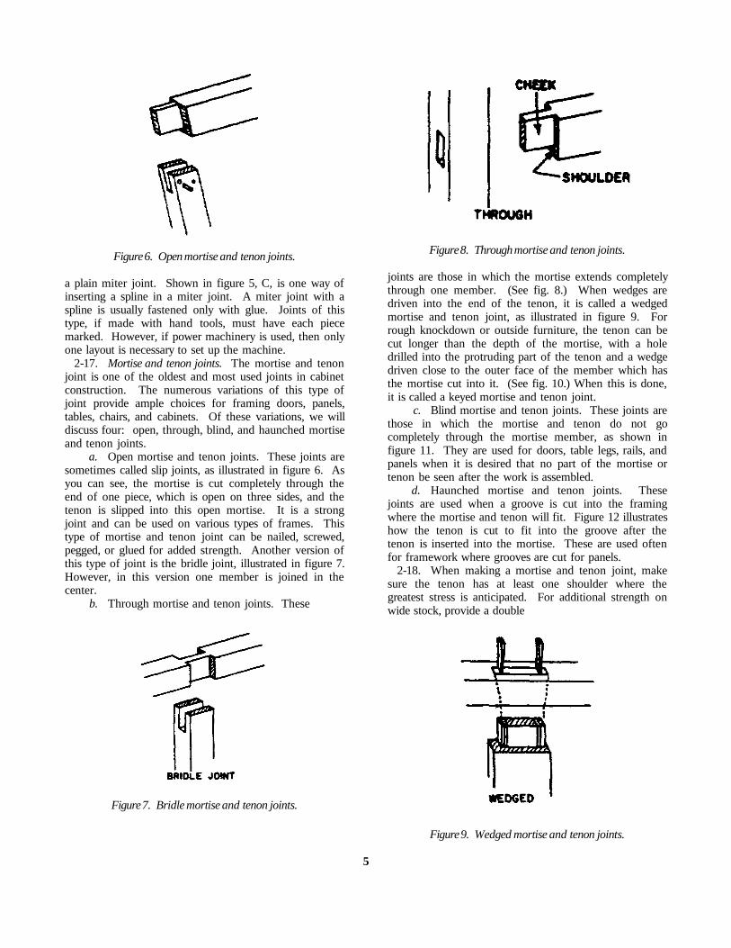
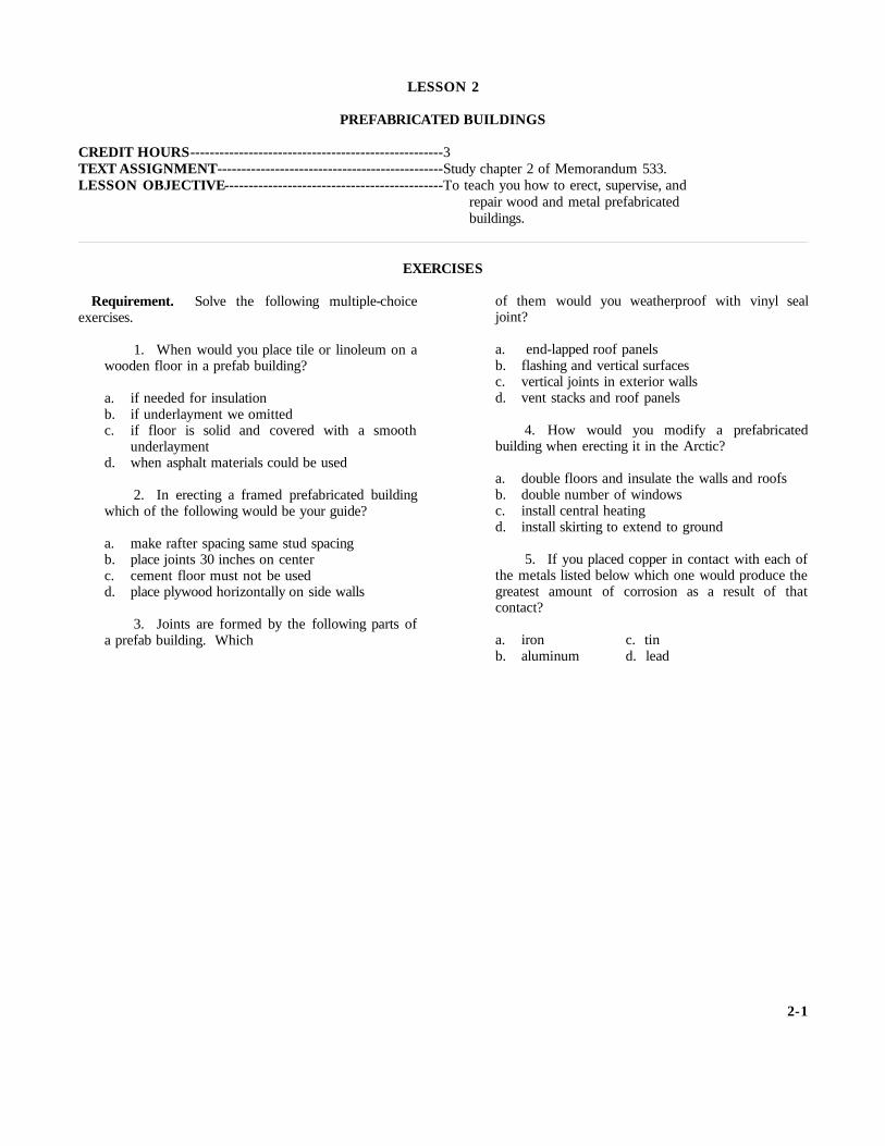
Figure 6. Open mortise and tenon joints.
a plain miter joint. Shown in figure 5, C, is one way ofinserting a spline in a miter joint. A miter joint with aspline is usually fastened only with glue. Joints of thistype, if made with hand tools, must have each piecemarked. However, if power machinery is used, then onlyone layout is necessary to set up the machine.
2-17. Mortise and tenon joints. The mortise and tenonjoint is one of the oldest and most used joints in cabinetconstruction. The numerous variations of this type ofjoint provide ample choices for framing doors, panels,tables, chairs, and cabinets. Of these variations, we willdiscuss four: open, through, blind, and haunched mortiseand tenon joints.
a. Open mortise and tenon joints. These joints aresometimes called slip joints, as illustrated in figure 6. Asyou can see, the mortise is cut completely through theend of one piece, which is open on three sides, and thetenon is slipped into this open mortise. It is a strongjoint and can be used on various types of frames. Thistype of mortise and tenon joint can be nailed, screwed,pegged, or glued for added strength. Another version ofthis type of joint is the bridle joint, illustrated in figure 7.However, in this version one member is joined in thecenter.
b. Through mortise and tenon joints. These
Figure 7. Bridle mortise and tenon joints.
Figure 8. Through mortise and tenon joints.
joints are those in which the mortise extends completelythrough one member. (See fig. 8.) When wedges aredriven into the end of the tenon, it is called a wedgedmortise and tenon joint, as illustrated in figure 9. Forrough knockdown or outside furniture, the tenon can becut longer than the depth of the mortise, with a holedrilled into the protruding part of the tenon and a wedgedriven close to the outer face of the member which hasthe mortise cut into it. (See fig. 10.) When this is done,it is called a keyed mortise and tenon joint.
c. Blind mortise and tenon joints. These joints arethose in which the mortise and tenon do not gocompletely through the mortise member, as shown infigure 11. They are used for doors, table legs, rails, andpanels when it is desired that no part of the mortise ortenon be seen after the work is assembled.
d. Haunched mortise and tenon joints. Thesejoints are used when a groove is cut into the framingwhere the mortise and tenon will fit. Figure 12 illustrateshow the tenon is cut to fit into the groove after thetenon is inserted into the mortise. These are used oftenfor framework where grooves are cut for panels.
2-18. When making a mortise and tenon joint, makesure the tenon has at least one shoulder where thegreatest stress is anticipated. For additional strength onwide stock, provide a double
Figure 9. Wedged mortise and tenon joints.
5
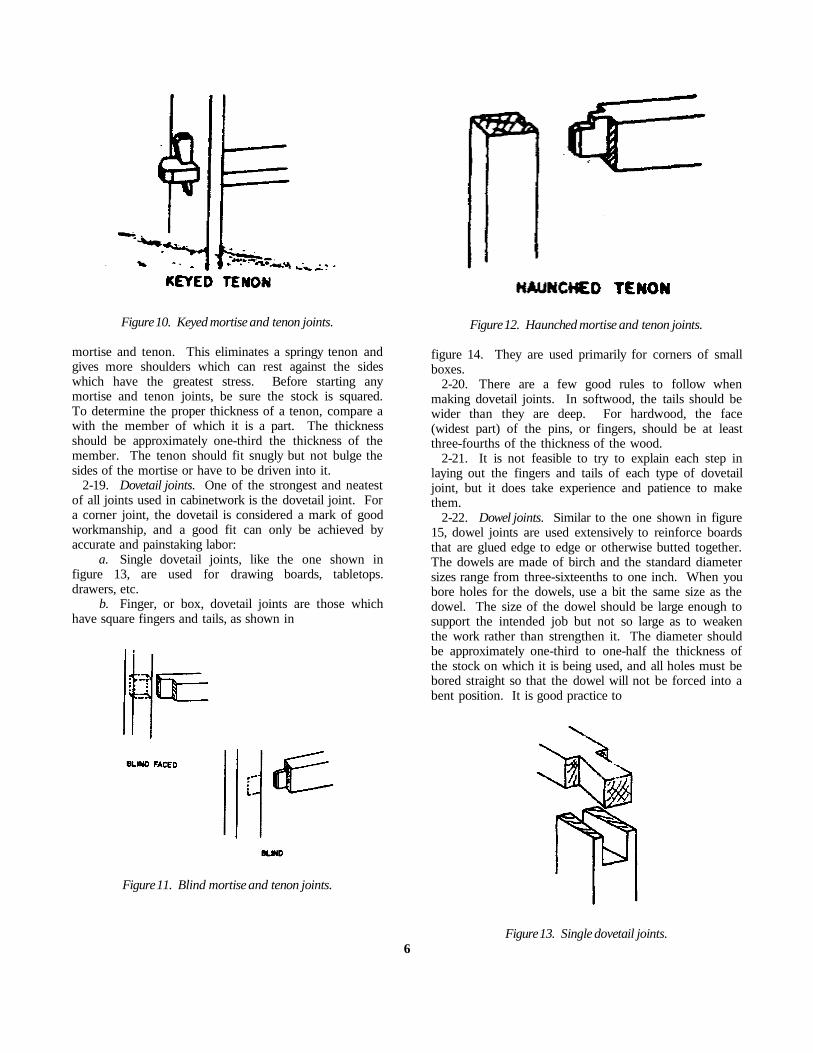
Figure 10. Keyed mortise and tenon joints.
mortise and tenon. This eliminates a springy tenon andgives more shoulders which can rest against the sideswhich have the greatest stress. Before starting anymortise and tenon joints, be sure the stock is squared.To determine the proper thickness of a tenon, compare awith the member of which it is a part. The thicknessshould be approximately one-third the thickness of themember. The tenon should fit snugly but not bulge thesides of the mortise or have to be driven into it.
2-19. Dovetail joints. One of the strongest and neatestof all joints used in cabinetwork is the dovetail joint. Fora corner joint, the dovetail is considered a mark of goodworkmanship, and a good fit can only be achieved byaccurate and painstaking labor:
a. Single dovetail joints, like the one shown infigure 13, are used for drawing boards, tabletops.drawers, etc.
b. Finger, or box, dovetail joints are those whichhave square fingers and tails, as shown in
Figure 11. Blind mortise and tenon joints.
Figure 12. Haunched mortise and tenon joints.
figure 14. They are used primarily for corners of smallboxes.
2-20. There are a few good rules to follow whenmaking dovetail joints. In softwood, the tails should bewider than they are deep. For hardwood, the face(widest part) of the pins, or fingers, should be at leastthree-fourths of the thickness of the wood.
2-21. It is not feasible to try to explain each step inlaying out the fingers and tails of each type of dovetailjoint, but it does take experience and patience to makethem.
2-22. Dowel joints. Similar to the one shown in figure15, dowel joints are used extensively to reinforce boardsthat are glued edge to edge or otherwise butted together.The dowels are made of birch and the standard diametersizes range from three-sixteenths to one inch. When youbore holes for the dowels, use a bit the same size as thedowel. The size of the dowel should be large enough tosupport the intended job but not so large as to weakenthe work rather than strengthen it. The diameter shouldbe approximately one-third to one-half the thickness ofthe stock on which it is being used, and all holes must bebored straight so that the dowel will not be forced into abent position. It is good practice to
Figure 13. Single dovetail joints.6

Figure 14. Finger or box dovetail joints.
cut the dowels one-eighth inch shorter than thecombined depths of the holes and to point the end withcoarse sandpaper or a knife. Dowel joints are alwaysglued and are often used as a substitute for mortise andtenon joints. To allow air and excess glue to escape, cuta channel, or spiral, the full length of each dowel.
2-23. Corner joints. Corner joints, other than themitered, butted, doweled, or dovetailed types, are usedextensively in the construction of drawers for furnitureand cabinets. A corner joint is shown figure 16. A.One member of the joint is rabbeted, with the othermember fitted into the rabbet and fastened with glue,nails, screws, or a combination of glue and a metalfastener. The box corner joint, shown in figure 16. B.consists of two members, one dadoed and the otherrabbeted to fit the dado. This corner joint is pri-
Figure 15. Doweled joints.
marily used for the rear corners of drawers. The milledcorner joint, shown in figure 16, C, consists of twomembers with milled grooves that are fisted together.This joint is used for the front corners of drawers,because it will resist the pull exerted on the front of thedrawer.
2-24. By now you should have a good idea of both thewood used and the types of joints required to constructan article. With this information firmly in mind, let'stake a look at the recommended procedures forconstructing a wooden article.
2-25. Butt joints. The butt joint consists of twomembers that are fastened together end to end withoutoverlap. This joint is often strengthened with a strap orstraps.
3. Constructing Wooden Articles
3-1. You can probably remember the furniture inyour grandmother's home when you were a youngster.Today, your grandmother's furniture would be consideredas old fashioned as that
Figure 16. Corner joints.
of her grandparents, because designs and styles continueto change. Modern-day furniture designers try to createfurniture that will give us convenience, comfort, andbeauty.
3-2. Along with the many style changes, massproduction methods and new materials have changedcabinet construction procedures. However, the basicforms of construction remain relatively the same as theywere when our so-called antiques were made. Today,however, there are more "built-ins" in the form ofcabinets, dressing tables, and workcounters.
3-3. This section will provide you with the knowledgeyou will require to construct and repair cabinets; it willalso cover types of construction, which include frame,stool, and box. The procedure used in the selection ofmaterials for the items covered in this section are alsoextremely important and should be followed as closely aspossible.
3-4. The last two major topics in this section are theassembling of parts into complete units
7

Figure 17. Frame construction.
and final inspection of your finished work. Obviously,knowledge of construction fundamentals and of whichmaterials should be selected-and how-is useless to you ifyou do not put your piece of work together adequatelyand carefully check your completed article.
3-5. You may have the opportunity to construct newcabinets, or your work may consist only of rebuildingdamaged ones. Remember to apply what you havelearned. By doing so, you will produce an article out ofwood that will make you proud to say, "I made it."
3-6. Constructing Cabinets. Before you startconstructing a cabinet, become familiar with all of thebuilding details and prepare a bill of materials. As youstudy your drawing, you will find that the article to beconstructed can be classified in one of three forms ofcabinet construction. Regardless of the cabinets youmake, use one of the three general forms (frame, stool,or box) or a combination of them. These three formsare the basis for all cabinet construction and can beadapted to fit any design; however. special methods mustbe used where intricate shape are desired.
Figure 18. Stool construction.
3-7. Frame construction. Frame construction consistsof a grooved frame and a panel which fits into thegroove. The framework adds strength because the grainof the wood runs lengthwise in both length and width.Frame construction is highly desirable, because itovercomes shrinkage and swelling and provides amplestrength for the panel. Figure 17 illustrates a simple typeof frame construction which is used extensively incabinet construction. The various joints we have coveredcan be used to fasten the frame together.
3-8. Stool construction. As shown in figure 18, stoolconstruction may be regarded as four frames put togetherto form a rectangle or square. It is used for tables,chairs, stands, and many types of cabinets. Mortise andtenon joints and dowel joints work well in stoolconstruction. When fitting this type of construction witha top (for example, a tabletop), do not secure the topwith glue, because wood shrinks across its width and thetop must be able to give with the shrinking
Figure 19. Securing tops.
and swelling process. Figure 19 illustrates how a tabletopis secured in stool construction. If the rails and topshrink or swell, then the top can move without splitting.
3-9. Box construction. Box construction is used forarticles made from solid wood, such as chests of drawers,cupboards, and bookcases. Any item built without aframework comes under the heading "box construction."Figure 20 illustrates one type of box construction. Whenusing the box construction method, use rabbet, butt,mitered, or dovetail joints.
3-10. Selection of Materials. Now that we havediscussed the three forms of cabinet construction, let'sassume that we have our drawing, have checked all thedetails, and have made out our bill of materials. Afterthis assumption, select the materials needed. Whenselecting materials for your project, bear in mind howand where the article will be used. Normally, you wouldnot use the most expensive trade of ma-
8

Figure 20. Box construction.
terial for a cabinet which would be used for tools. Howthe article will be finished also has a bearing on thematerial you will use. If your article is to be painted, usematerial with minor defects that the paint will cover. Ifthe article is to have a clear finish, then use a bettergrade of material.
3-11. After the material has been selected, you areready to mill the stock and form it according to theblueprint or drawing.
3-12. Posts or legs used in stool type construction tosupport articles such as tables, chairs, and stools are oftenmilled to decorative shapes, using the wood lathe. Referto your blueprint for the size of the posts, and mill themto these specified sizes and shapes.
3-13. Fasten posts to the rails (see fig. 18) withmortise and tenon or dowel joints. If mortise and tenonjoints are used, mortise each a side rail, while the otherside receives one tenon of an end rail. If doweled jointsare used, drill dowel holes on the sides in place of themortises. When you make mortises or dowel holes, pairoff your posts; in other words, label them left and right.As you do this, keep the best sides for the face sides.The face sides are those which will be seen when thearticle is assembled.
3-14. Rails, when assembled with posts, form a squareor rectangular-shaped frame supported by the posts.Your blueprint will give you the dimensions for thelength and width of the rails. The material you selectedmust be milled to these dimensions, using the jointer,planner, and table and cutoff saws. When you cut therails to length, add the length of each tenon if mortiseand tenon joints are used. Rails that are fitted with apanel, as shown in figure 21, must have a groove cut onthe pane edge of each rail.
3-15. Tops are used in all three forms of constructionpreviously mentioned. Most often, they are large enoughto require two or more pieces of stock to be gluedtogether. The pieces can be joined with glue, usingvarious types of joints, such as the tongue and groove.butt, and dowel. When selecting the material to be gluedtogether, make the selection so that each piece hassimilar grain characteristics, and glue them so that thegrain of each piece has some semblance of matching.We repeat, the method used to fasten the top to acabinet or piece of furniture is an importantconsideration, because of the swelling and shrinking ofthe top.
3-16. In your job, you will probably install laminatedplastics on some surfaces, especially cabinet tops. Theseplastics are manufactured in sheets, or rolls, ready for use;therefore, the only thing you have to do is to install them.Laminated plastics also come in different lengths, widths,and thicknesses. When you install this material, select thenearest size sheet, or roll, to the size you need for yourparticular job. After you select the correct size materials, besure that both surfaces to be bonded are smooth, clean, anddry. Before you open the contact cement container, readthe instructions on the container and follow themreligiously, because the contents in the container areextremely flammable and harmful or fatal if swallowed.Shake the contact cement in the container vigorously beforeyou use it. Open the container and, using a short-fibered
Figure 21. Rails fitted with panel.
9

Figure 22. Dado and mortises for box construction.
paint roller or a wide brush, spread the contact cementon the back of the laminated plastic top and on thesurface to which you are going to apply the plastic. Onefull coat is usually enough on nonporous surfaces (backof laminated
materials or metal). Porous surfaces, such as wood,usually require two coats. When you use more than onecoat of contact cement, allow it to dry thoroughlybetween coats. Be sure that you allow the contactcement to dry before you bond the laminated plastic top.Position the surfaces carefully, because no adjustment ispossible after the contact cement films make contact Usescrap plastic, thin wood, metal strips, screen wire, orsome other material to separate the contact cement filmswhen you are positioning large pieces of laminatedplastics. Apply pressure immediately and firmly with a 3-inch-wide roller or a rubber-faced hammer, working fromthe center to the edges over the entire surface. Onlymomentary pressure is needed, but the more pressure youapply within the limits of the bonded material, thestronger the bond will be. Trim and finish the job with arouter as soon as you have completed the bondingprocess. You can knock the sharp edges off with a file ifneeded.
3-17. Sides, ends, or backs can be constructed withframe, stool, or box type construction or a combinationof all three. For a combination of frame and stoolconstruction, the sides would be paneled, as illustrated infigure 21. This requires an upper and lower rail with agroove cut into the rails and the posts. This type ofconstruction is used primarily for desks. The plywoodused for the panels should have the best side out forappearance sake. The same applies to the rails and posts.Be sure to cut the panels square and to remove the roughedges from around the panel. Smooth edges will help thepanel slide into the groove easily. The groove must belarge enough for the panel to slide into without its beingdriven.
3-18. In box type construction, the sides and ends areusually solid, similar to a top. Articles such as dressersand chests of drawers usually have the pieces which makeup the ends and sides glued to make them wide enough.Check your drawing for the correct dimensions and allowa little extra so that you can mill the sides and ends tothese dimensions after the pieces have been gluedtogether. In this type of construction, the solid sides orends are rabbeted on the back edge to receive the back,which is usually a piece of plywood. The rabbet is cutafter the stock has been milled to the specified size. Theinterior side may also need dados or mortises cut toreceive drawer rails or shelves, as shown in figure 22.These are cut to the correct size and depth after themilling process.
3-19. Frame type construction for sides, ends, or backs(see fig. 23) is made by assembling the various panelstogether according to your drawing. When you form thevarious parts, keep the best sides out for the rails andpanels. Cut the
10


Figure 23. Panels for frame construction.
panels square, remove the rough edges, and be sure thatthe groove is large enough to receive the panel.3-20. Doors used on cabinets and furniture can beclassified as paneled or flush. Flush doors are usuallymade solid or with a frame covered with plywood. Theframe for panel doors can be mortised and tenoned,doweled, lapped, or mitered. Your drawing will give youthese details. The material for the framework is milledto the dimensions specified on your drawing. After themilling process, the rails and stiles are cut to length. Thematerial for the framework is milled to the dimensionsspecified on your drawing. After the milling process, therails and stiles are cut to length. The joint to be used ismade along with a groove in each rail and stile for thepanel. Sometimes a molding is cut on the inside edge ofthe frame near the panel. (See fig. 24.) Before cuttingthe molding, select the best side of the frame to showwhen the doors are closed. If any joint other than amiter joint is used, the molding must be mitered, asshown in figure 24. The hinged side of the door shouldbe planed true with the top and bottom, and the lock sideshould have a slight angle to provide clearance
for opening. When you fit doors, remove the wasteequally from all stiles and rails so that their width willstay balanced.
3-21. Flush doors for most cabinets are solid and arecut to the specified dimensions shown on your drawing-making sure the tops, bottoms, and hinged sides are true.
3-22. Regardless of the type of door, the materialselected must be straight and have good graincharacteristics. If the material for the doors must beglued, match the grain characteristics. When you millout material for more than one door-especially for doubledoors-do it all at one time.
3-23. If the article you make has drawers., there willusually be a detailed drawing of the drawer constructionalong with your blueprint. Check your plan for thethickness and width of the sides, front, and back of eachdrawer, and then mill the stock to these dimensions.When you start cutting the joints for a drawer, mark thepieces "sides," "fronts," and "backs," with the side piecesmarked "lefts" and "rights." The reason for this is thatbottoms of most drawers are inserted into grooves cut onthe inside of each side, front, and back piece of drawer.This is clearly illustrated in figure 25. Plywood used forthe bottom of the drawers should have the good side upso that it can be seen when the drawer is opened. It isessential to have all material cut square if the drawer is tofit well. Wood used for side and back pieces can haveslight defects; however, they must be placed so that theycannot be seen from the inside when the drawer is open.Material for the drawer fronts
Figure 24. Molding on paneled door.
11

Figure 25. Detail for drawer construction.
should have a pleasing grain, and if more than onedrawer is used, the grain characteristics should be similaron each front. This is true for a clear finish but is notimportant if your articles will be painted. Your drawingmay call for a false front on a drawer (see fig. 25); if so,the material should be carefully selected and milled to thedimensions specified.
3-24. We have discussed the various parts you willhave to mill in any one of your projects. Before youbegin to assemble any of these pans into units, sand eachpart to remove toolmarks or other blemishes. Thegreater portion of the sanding should be completedbefore the parts are assembled, so that after an article isassembled, it needs only touchup sanding to have it readyfor finishing.
3-25. Always sand with the grain-never across it-oryou will mar the surface of the wood with scratches.Figure 26, A, illustrates the correct direction the sandblock should move when you are sanding by hand. Theother three parts of figure 26 show incorrect use of thesand
motion when sanding flat surfaces; instead, use long,even strokes.
3-26. If parts of the article you are making haveirregular curves, sand them on the spindle part of the diskand spindle sander; however, if a sander is not availableand the curves are long, sand by hand with a block. Theblock guards against rounding the edges. Sand insidecurves by hand, using a stick with a rounded surface.(See fig. 27.)
3-27. For all lathe turnings, such as the posts fortables, stools, or the rungs of chairs, make sure eachturning is sanded to a smooth surface before you beginany assembly work.
Figure 26. Direction for sand block.
12
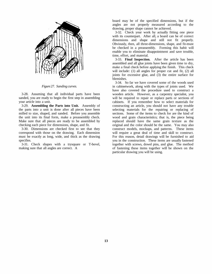
Figure 27. Sanding curves.
3-28. Assuming that all individual parts have beensanded, you are ready to begin the first step in assemblingyour article into a unit.
3-29. Assembling the Parts into Unit. Assembly ofthe parts into a unit is done after all pieces have beenmilled to size, shaped, and sanded. Before you assemblethe unit into its final form, make a preassembly check.Make sure that all pieces are ready to be assembled bychecking each piece for dimensions, shape, and fit.
3-30. Dimensions are checked first to see that theycorrespond with those on the drawing. Each dimensionmust be exactly as long, wide, and thick as the drawingspecifies.
3-31. Check shapes with a trysquare or T-bevel,making sure that all angles are correct. A
board may be of the specified dimensions, but if theangles are not properly measured according to thedrawing, proper shape cannot be achieved.
3-32. Check your work by actually fitting one piecewith its counterpart. After all, a board can be of correctdimensions and shape and still not fit properly.Obviously, then, all three-dimensions, shape, and fit-mustbe checked in a preassembly. Forming this habit willenable you to eliminate disappointment and save trouble,time, effort, and material.
3-33. Final Inspection. After the article has beenassembled and all glue joints have been given time to dry,make a final check before applying the finish. This checkwill include: (1) all angles for proper cut and fit, (2) alljoints for excessive glue, and (3) the entire surface forblemishes.
3-34. So far we have covered some of the woods usedin cabinetwork, along with the types of joints used. Wehave also covered the procedure used to construct awooden article. However, as a carpentry specialist, youwill be required to repair or replace parts or sections ofcabinets. If you remember how to select materials forconstructing an article, you should not have any troubleselecting materials for the repairing or replacing ofsections. Some of the items to check for are the kind ofwood and grain characteristics; that is, the piece beingreplaced should have the same grain texture as theoriginal and the color should be the same. You may alsoconstruct models, mockups, and patterns. These itemswill require a great deal of time and skill to construct.For this reason, detail drawings will be furnished to aidyou in the construction. These items are usually fastenedtogether with screws, dowel pins, and glue. The methodof fastening these items together will be shown on theparticular drawing you will be using.
13

CHAPTER 2
Prefabricated Buildings
TODAY, ARMY installations all over the world are usingprefabricated buildings. These buildings are used mostlyin localities where materials cannot be purchased locally.To save time and material, as well as to simplify erection,prefabricated buildings are standardized and available foruse in Temperate, Tropic and Arctic regions.
2. As a carpentry specialist, you will be erectingprefabricated buildings. Like other structures, they muststart with a good foundation. As we follow theprocedures for the erection of one of these buildings, youwill see that its construction is similar to that of anyframe building.
3. Besides constructing buildings, prefabricated orotherwise, much of your time will be spent in keeping thebuildings good repair. This is your work in maintenanceand repair. Maintenance and repair work will challengeall of your building skill. You will inspect work done byothers, some of it done a long time ago. Whether it waspoorly done or is just wearing out so that it could requireexpensive repairs, you will be able to correct the trouble.
4. This chapter discusses erecting, maintaining, andrepairing prefabricated buildings. It also discusses therequirements for constructing these buildings inTemperate, Tropic and Arctic regions.
4. Prefabricated Wooden Buildings
4-1. A prefabricated (prefab) wooden building isassembled of precut members. The joists, plates, studs,rafters, etc., are ready for assembly when they aredelivered to the building site. In some cases the precutpieces may be partially assembled into standard sizepanels. These pane may be designed for use with aframe or they may be shaped in such a manner that thecan be bolted together to form floors, walls, and roofs.Let's look at the construction of each type and themethod of making repairs.
4-2. Paneled Prefabricated Buildings. A woodprefab that is assembled of panels will have an
outward appearance similar to the building shown infigure 28. The vertical strips used to cover the jointsbetween the exterior wall panels distinguish this buildingas a panel type prefab. Look at figure 29 and thencompare it with figure 28. Figure 29 shows a partiallyassembled panel type prefab building, while figure 28shows a completed building. Note the distinct lines madeby the joints between the panels. Also, note in figure 29that the framework is a part of the panel and that noseparate framing is required.
4-3. Floors. The floor of a panel prefab buildingconsists of flooring, joists, and girders. The boards arefastened to two or three joists to form a panel 4 feetwide and 8 feet long. The panels are placed on girdersthat are supported by posts or column. The panels arefastened in place with screws, and the joints between thepanels are covered with a T-shaped metal strip. Whenplywood is used for the floor, the edges are protected byan H-shaped metal strip that is inserted between twopanels. This strip also prevents dust and small objectsfrom collecting in the joint. The panels are easilyremoved without damaging the edge or the metal strip.If you remove the end or side panels first.
4-4. Repairs can be made to individual floor panels inthe same manner repairs are made to floors in otherbuildings. Also, the panels are interchangeable. Repairedor weak panels may be moved from the main path oftraffic and exchanged with stronger panels located inother parts of the building.
4-5. There is a variety of floor panels for this type ofbuilding, but only one type should be used on your post.Some panels have a subfloor, insulation, or both. The typeyou use will depend on the particular use to which panelswill be put and the climate in which they will be used. Forexample, flooring which must have heavy equipment mustobviously be much stronger than that which will bear lightequipment. Again, panels intended for use in hot, humidclimates, such as are common in the Trop-
14

Figure 28. Prefabricated wooden building.
Figure 29. Prefabricated wooden panel building.
15

ics, are not, for this reason alone, suitable for use in thecold, low humidity, and dryness of the Arctic regions.
4-6. Walls. The panels used for the exterior wallsconsist of an exterior covering on a light frame. Thecovering may be fiberboard, plywood, or siding. Theframe may be made of 1x1, lx2, 1 1/2x1 l/2-, or 2x2-, or2x3-inch material. Where insulation is required, afiberous filler is installed between the exterior andinterior coverings.
4-7. Doors and windows are assembled within astandard size 4x6-or 4x8-foot panel. The panels areinterchangeable so that you can relocate windows, door,and solid sections as desired.
4-8. The wall panels are fastened in place withdouble-head scaffold nails or lag screws (bolts). Bolts areused to fasten two panels together along the vertical edge,as shown in figure 29. The fasteners used in this prefabcan be easily removed without damaging the panels.
4-9. Repairs to wall panels usually consist of replacinglx2 or 1x4 strips over the vertical joints and replacing wallcoverings. The parts of insulated panels are assembledwith glue and cannot be disassembled. You can repair adamaged area on a fiberboard covered panel by installinga fiberboard patch. Make the patch large enough so thatyou can fasten at least two edges of it to the framingmembers. Use a waterproof glue to fasten the other twoedges. Glue may also be used to fasten small plywood orfiberboard patches if they cannot be fastened to theframe.
4-10. Sticking doors and windows are a problem inthis type of building when the panels weaken or begin towarp. If normal adjustments do not correct the situation,you may have to strengthen the panel. Replacing thepanel covering with new material will give it additionalstrength. Adding an interior covering on the panel willalso help to reduce its flexibility and keep it straight.
4-11. The panel type prefab building does not havecorner braces. As the building becomes older, it isweakened, and wind pressures may cause the building tolean or shift slightly and the windows and doors to bind.You can use guy wires at each corner to help preventexcessive shifting of the panels. The guy wire should beattached at the top of the corner panel or near the eaveof the corner roof panel. The other end of the wire maybe fastened to a stake, another prefab building, or a solidstructure. These guy wires are a part of the originalassembly when the prefab building is used in an area ofstrong prevailing winds.
4-12. Roof. Roof panels are built according to theclimatic conditions that exist where the
building is to be used. A panel that consists of a 2x2-inch frame and fiberboard covering is sufficient for someareas. Heavier 2x4 frames are used with one inchdecking or plywood where snow loads are expected.Insulated panels are used in both hot and cold climates.
4-13. Roof panels are fastened at the top of theexterior wall panels and at the ridge. A ridge board isplaced between the upper end of two roof panels, andbolts are used to hold them together, as shown in figure29. The side members (rafters) of the panel frame arebolted to adjoining panels.
4-14. Some roof panels have offset edges so that theyfit together with a lap joint (see fig. 1 and pars. 2-9 and2-10 in ch. 1) like shiplap lumber. This joint helps inlining up the panels and also helps in preventing leaks.The joints between the panels are sealed by coveringthem with a bitumen adhesive and cloth strip. Sinceexpansion, contraction, or any other movement of thepanels will damage the joint seal, you will probably haveto renew or replace the seal every year or two. Whenextended usage is planned for the building, it is best tocover the entire roof with a layer of roll roofing. Theroofing can be cut at the panel joints when the buildingis disassembled.
4-15. The roof on this panel prefab building is not asstrong as standard wood construction. Therefore, youmust be careful when you check or repair the roof panels.Make a temporary walkway by using a 1x12-inch board(with cleats) that will extend from the cave to the ridge.When you replace joint seals, start work at one end ofthe building and work toward the other to avoid walkingon or near the repaired area. Don't walk back across thepanels after completing your work. Unnecessary walkingon the roof will break the joint seals, and you will haveto replace them again.
4-16. Framed Prefabricated Buildings. The framedprefabricated wooden building is also known as a precutor light frame building. The framing is precut andprepared for assembly before it is delivered to the jobsite. The studs and rafters are widely spaced, as shownin figure 30. Let's take a look at the construction of thisbuilding.
4-17. Floors. The floor of the framed prefab buildingconsists of flooring, joists, and girders. A combinationsubfloor and finish floor is used where a smooth finish orthe additional insulating value is required. Girders extendaround the perimeter and along the centerline of thebuilding to support the joists. The joists are spaced 24inches on-center with each length of joist spanning thedistance between the girders. The
16

Figure 30. Prefabricated wooden frame building.
subfloor is laid either diagonally or perpendicular to thejoists. The finish floor, if one is used, is laid lengthwisein the building. This type of building may also be usedwith a concrete slab floor.
4-18. Repairs to the floor consist of replacingindividual pieces of flooring. Recovering with a layer ofplywood may also be justified if the walls and roof are ingood condition and the building can be used for severalmore years. Use a layer of 15-pound felt between thelayers of flooring to prevent dust from entering throughthe joints. Tile and linoleum are not used on woodfloors if the floor is not reasonably solid and coveredwith a smooth underlayment.
4-19. Walls. The walls in the framed prefab consistof studs, plates, girts, and braces. The sidewalls havestuds spaced 4 feet on-center and the end walls havestuds at the corner and beside the door opening. Singletop and bottom plates are used on the ends of the studs.The bottom, or sole plate, is placed on top of thesubfloor and is fastened to the subfloor and joists as inplatform construction. The girt is a horizontal memberlocated at about the center height of the wall. It servesas a fastening surface for exterior wall coverings. Noticethe horizontal gins in the end section in figure 30. Thesegirts serve as a fastening surface for 4x8-foot sheets ofplywood that are place horizontally.
The plywood may be placed either horizontally orvertically on the sidewall. Sheets placed horizontally helpto brace the corners. Knee braces (see fig. 30) in endsections extend from the top plate at a corner to thebottom plate at the door opening. Set-in bracing (shortlengths of 2x4's nailed between the studs at an angle)may be used in the sidewalls. Corner braces (see fig. 30)extend across a corner, from top plate to top plate, tohold the corner square.
4-20. The exterior wall covering may be 1-inchsheathing, fiberboard and insulation panels, or plywood.Rigid insulation boards may be installed as a firstcovering, followed by a felt membrane, a layer ofplywood, and a layer of roofing felt. The roofing feltprotects the exterior wall from moisture and eliminatesthe need for painting. Thin wooden strips or wood latheare used to hold the roofing felt in place.
4-21. Your work on the exterior walls consists ofadding additional bracing, repairing windows and doors,and replacing sheathing and felt. Torn felt should bereplaced and fastened with wood strips. Check the woodstrips that hold the felt covering in place. Draw loosenails up tight to hold the strips firmly against the felt.
4-22. Roof. The roof consists of precut rafters, ceilingjoists, and braces that can be assembled on the job tomake a truss. The ceiling joist extends the full width ofthe building and
17

is fastened to the lower ends of the rafters. The lowerend of the rafter is seated on the top plate of thesidewalls, as shown in figure 30. The joint made by thejoist and rafter is very important The joist helps toprevent the lower end of the rafter and the top of thewall from moving outward. Perhaps you have noticedbuildings where the sidewalls bowed outward and theridge sagged in the middle. This is possible when therafter and top plate pull loose from the ceiling joist. Theload on the rafter forces the upper part of the walloutward, and the ridge line becomes lower. This alsohappens in permanent structures but is most common inlight frames, where fewer and lighter ceiling joist areused.
4-23. The rafter spacing is the same as stud spacing,4-foot on-center. A knee brace fastened to the rafter,ceiling joist, and wall stud is used every 12 or 16 feet forthe length of the building. One-inch sheathing boardsare used for the roof deck. Roll roofing is used as theroof covering. There is no roof overhang at the eave orgable, and the roof covering is lapped down the side wallsto prevent leaks along the edge of the roof.
4-24. The interior of the light frame prefab is usuallyopen, and leaks are easily located by a visual inspection.When a ceiling and partitions are used in the building,you must locate leaks by entering the attic or going onthe roof. Don't walk around on the roof any more thanis absolutely necessary. Instead, you should locate theleak by entering the attic and checking for water marks.Then go on the roof and make the repair. Use a 1 x 12for a walkway and avoid walking between the rafters.The wide spacing of the rafters allows the decking to sagwhen you walk on it Of course, old, brittle roofing maybe broken beyond repair, and the only feasible way to fixleaks may be to put on new rolled roofing.
4-25. Most repair work on the framed prefab buildingis similar to the repair work on a standard framestructure. Just keep in mind that this is a light framebuilding. Repairs to the frame usually consist of nailingsplices beside the faulty member rather than attemptingto replace the frame.
4-26. Now that we have discussed wooden prefabbuildings, let's see how prefabricated metal buildings areassembled and repaired.
5. Prefabricated Metal Buildings
5-1. The prefabricated metal buildings in use onsome military installations are constructed of manydifferent types of metal. However, galvanized sheetmetal and aluminum are the most common metals usedin prefab buildings. Most metal prefabs are referred to asportable buildings, because they are easy to disassembleand
relocate. When they are no longer needed in one area,they can be shipped to an area where they can serve auseful function. We will concentrate our attention upontwo metal buildings that are frequently used: theadvanced base hut and the light steel frame buildings.
5-2. Advanced Base Hut. The advanced base hut isusually referred to as a "quonset hut". The standard sizeis 20 by 48 feet. However, you will find that some ofthem are two or three times as long as this. They areplanned so that they can be assembled in sections 8-footlengths to make a building 8, 16, 28, etc., feet long. Theyare easily adapted for quarters, office space, workshops,training areas, supply storage, or any other function thatcan be placed within them. Nails, screws, and bolts usedin the assembly of the quonset hut are easily removedwhen repair or disassembly of the unit is required. Theprimary parts of this hut are the floor and wall, so let'ssee how they are put together.
5-3. Floors. The floor of the hut consists of a metalframe with a plywood covering. The main support of thebuilding is provided by five girders that run the length ofthe building. These I-shaped girders are spacedapproximately 5 feet 1 inch on-center to provide supportfor the floor joists. The girder, as we called it in thewooden building, is referred to as an I-beam (its shape)or joist sill (its function) in metal construction. Joistsspaced 2 feet on-center are placed on, and perpendicularto, the joist sills, as shown in figure 31. A U-shapedchannel plate fastened to
Figure 31. Sill and joist assembly.
18

Figure 32. Joint and spline.
the top of the joists borders the floor and serves as afastening surface for the end wall studs and arch ribs.Figure 32 shows the arch ribs connected to the channelplate. This channel plate is comparable to the bottomplate used in a wood frame building.
5-4. The floor is made of 4x8-foot sheets ofplywood. Twelve sheets of plywood are placed side byside on the joist along each sidewall to cover the lengthof a 48-foot building. The two rows of sheets are buttedagainst the channel plates of the side walls. Six sheets ofplywood placed end to end fill the remaining 4 feet inthe center of the building. The actual floor widthbetween the channel plates is 20 feet 1 inch, or 1 inchmore than the 2 lengths and 1 width of the plywoodsheets used as the floor covering. This 1-inch space isdivided between the two center joints to allow a 1/2-inchcrack between the ends of the side sheets and the edgeof the center sheets. These joints are protected by theH-shaped metal floor splines, as shown in figure 33. Thisspline protects the edge of the plywood, keeps the jointclean, and allows for movement of the plywood sheets.The wide joint and the slip-on spline make it easy for youto remove the center sheets, which are subjected to themost wear. Only 3 or 4 nails are used to fasten a sheetinto place. Sixpenny common nails are driven throughthe plywood and into the groove in the joist. Notice thegroove or separation along the top and bottom of thejoist shown in figure 31.
5-5. Walls. The end walls of the hut consist ofmetal studs, channel plate, window and door headers, andcorrugated sheet metal siding. The studs set in thechannel are fastened into place with roundhead sheetmetal screws. One screw is placed through the insideedge of the channel, and another is placed through theoutside edge of the channel. There are 4 screw holes inthe end of the stud, but it is not necessary to fastenthrough each of them except to splice two lengths
of channel plate. Alternate holes, inside right and outsideleft or inside left and outside right, are normally used.To remove a stud, you must gain access to both theinside and outside screws. Figure 34 shows the locationof the framing members in an end section. The windowand door headers consist of channels that are fastenedbetween the studs. They serve as a fastening point forsiding, interior finish, and the window or door frame.
5-6. The sidewalls and roof are framed with archribs, purlins, and window headers. The arch ribs arespaced 4 feet on-center and extend from the channel tothe ridge or highest point in the building. Two arch ribsare spliced at the peak with splice plates and bolts toform a complete arch. The bottom of each arch rib isfastened in the channel plate with sheet metal screws.Headers for the side windows are fastened between archribs. Four purlins are fastened near the top of the arch,as shown in figure 34.
5-7. Corrugated sheet metal is used to cover thearch. It is fastened horizontally on the side of the archto cover the area from the lowest purlin to the joist sill.The curved sheets that cover the top of the arch areplaced across the purlins. Vents and roof jacks are builtinto the rounded sheets that are used on the purlins.These sheets are the same width and length as the othersand are interchangeable with them so you can relocatethe vents if necessary.
5-8. Repairs to the exterior walls usually consist ofreplacing the seals or retightening the fasteners aroundthe doors and windows. Figure 35 shows the shape of arubber seal that is used to prevent leaks at a joint madeby corrugated metal and a flat surface.
5-9. When insulation is used in the walls of thequonset hut, it is fastened to wooden strips that areplaced between the arch ribs. The interior coveringconsists of plywood panels, 1/2-inch thick, that are easilybent to fit the inside surface of the arch rib. An H-shaped spline is used along the sides of the plywood, anda wood strip is used to cover horizontal joints. Figure
Figure 33. Splicing channel plates.
19

Figure 34. End wall framing.
36 shows the complete assembly as it appears at thebottom of the wall. Be very careful when you remove aninside panel. If you should loosen the adjoining panels,they may spring from the ribs and you will have morethan a handful of panels at one time. Always haveanother worker with you when you remove the panels orcorrugated sheet metal, because it is a two-man job.
5-10. Light-Steel Frame Buildings. The light steelframe building is a common building or many bases. Itis usually a special-purpose build-
Figure 35. Rubber seal.
ing that has been put up to support one special function.The light-steel frame building is made in different sizes,with different types of light-steel frames. The frameshown in figure 37 is similar to the frames used forbuildings of 20-to 50-foot width, with bays 12, 16, or 20feet long, and exterior walls that are 10, 12, or 14 feethigh. A bay is the distance between columns along theside walls. A bay is the basic assembly, and a buildingconsists of one or more bays. There is no limit to thenumber of bays that can be placed end-to-end to form abuilding. The frame shown in figure 37 is often referredto as open-bay construction, because the are no supportsneeded in the bay. The area between the side walls isopen, unobstructed space.
5-11. Framing. The end wall frame is assembled ofprefabricated parts. Each piece of metal is shaped anddrilled for assembly before it leaves the factor. Theframe is set up on a concrete foundation or slab. Anchorbolts are placed in the concrete to provide solid fastenersfar the columns. Because the column is a verticalmember, a channel type base plate is used to secure thecolumn in place. The anchor bolts hold the base plate,and the base plate is bolted to the base of the column
20

Figure 36. Exterior wall assembly.
5-12. Roof beams, extending from the top of thecolumn to the peak of the roof, form the main supportsfor the roof. The roof beams follow the path of thecommon rafter and are joined at the ridge with spliceplates and bolts. Splice plates are placed on the top.bottom, and sides of the roof beams at the ridge.
5-13. End wall posts, or door posts, extend from thefoundation to the roof beam and are bolted in place ateach end. Door framing is attached to the door posts.The door header is fastened to the door header girt,which extends between the door posts. A girt thatextends from column to column across the end of thebay may also be used to secure the door header andtracks when a sliding door is used. A base angle (90°angle) is fastened to the foundation between the columnsto provide a fastening surface for the vertical siding. Thetop of the siding is fastened to an angle that is attachedto the roof beam. The eave strut provides a surface forfastening the top of the sidewall panels. Theintermediate fastening surfaces are provided by horizontalgirts on both end and side walls.
5-14. The sag rods, shown in figure 37, are used toprevent the girts from sagging between the columns. Sagrods are also used in the roof frame to help hold thepurlins in line. The rods may be thin channels that clipin place and are not adjustable, or they may be threadedrods that can be adjusted. These rods should be kepttight, but overtightening will force the girts out of lineand pull the screws loose in the siding.
5-15. Angles are installed vertically to frame louversand windows. The angles for the louver form a frame inthe upper part of the gable and provide a fasteningsurface for the louver frame
Figure 37. Prefabricated steel building.
21

Figure 38. Deep V-wall panel.
and the siding. Angles also fit between the Z-shaped wallgirts to provide a fastening surface for the window frame.
5-16. Notice the brace rods in figure 37. These bracerods are used to square the end bays of the building.The brace rods in the wall run diagonally from the top ofone column to the bottom of the adjoining column. Therods pass through slots in the columns, and a bevelwasher, flat washer, and nut are used on the ends of therods. Turnbuckles are used at an intermediate point inthe rod to provide for adjustment. The turnbuckle has aright-hand thread in one end and a left-hand thread inthe other so that it can be tightened or loosened on eachsection of the rod at the same time. Adjustments mayalso be made by tightening or loosening the nuts on theend of the rods. When you tighten one rod, you mustloosen the one that crosses it to provide for a shift in theframing. The brace rods between the roof beams serveto hold the bay square and must be considered if youadjust the brace rods enough to cause a shift in theframe.
5-17. Wall and roof coverings. The metal wallcovering may be a panel that contains a
layer of insulation or it may be some other type ofmaterial. Figure 38 shows two insulated panels joinedtogether with a vertical joint. With this type ofinstallation, the T-bar is secured to the wall girts, and themetal weather seal is placed over the T-bar to provide adurable, moisture-proof joint. The insulation of the firstpanel butts against the weather seal, and the metal sidinglaps over the joint. The next panel has the insulationbutted against the weather seal, and the metal siding lapsover the previous sheet to form a lap joint of 1 1/2 laps.A mastic seal is applied to the area of the lap before thesecond panel is installed. This mastic seal is permanentand should never have to be replaced, except when thepanel is replaced or the building in disassembled andrelocated.
5-18. Another type of ribbed wall panel that has aninsulated core is shown in figure 39. This panel has vinyljoint seals inserted along the edges. The vertical edges fittogether as do those of tongue and groove boards tomake a weatherproof joint.
5-19. The lap joint and the vinyl seal joint are the twocommon methods used to make weatherproof verticaljoints in exterior walls. The mastic seal used in the lapjoint of insulated panels is also used with sheetmetalsiding and roofing. The mastic comes in strips with amoisture-proof paper backing that looks like maskingtape. The strips are rolled like tape for easy handling.You unroll the tape and apply the mastic and backing onthe joint area. Leave the paper backing on the masticuntil you are ready to install the next panel. Just peel thepaper off to expose the clean layer of mastic when youare ready to cover the joint. This mastic is also requiredin the horizontal joints of roof panels to prevent waterfrom being blown under the top panel.
5-20. When horizontal joints are required in
Figure 39. Ribbed wall panel.
22

Figure 40. End lap of exterior wall panel.
a wall, they are formed by lapping an upper panel over alower panel, as shown in Figure 40. A Z-shaped bar isused at the girt where the splice is made. The metalcovering of the lower panel extends above the Z-bar, andthe metal covering of the upper panel laps over the lowerpanel to form a 6-inch lap joint.
5-21. A solid rubber seal is used to make a waterproofjoint where ribbed panels overlap a smooth surface.Figure 41 (A, B, C, and D) shows the shape of the rubberseals used with roof and wall galvanized sheet metalpanels (A), aluminum ribbed panels (B), asbestos-cementpanels (C), and corrugated glass panels (D). The seals areplaced under the panel to prevent moisture from gettingbetween the panel and the smooth surface.
5-22. Special rubber seals may also be used at eavestruts, as shown in figure 42. Metal closure strips may beneeded, in addition to the
Figure 41. Rubber seals.
rubber seals, to close the space between the ribs of thepanel.
5-23. Figure 42 also illustrates the type of informationyou can get from the master file of drawings in thedrafting section. This drawing shows a side view of eachpart of the eave assembly. Each part is identified byshape, name, size, or type of material. Check thedrawing file to locate hidden parts of the building so thatyou can plan your work accordingly.
5-24. Sheet metal siding is fastened to the girts, baseangle, and eave strut or gable angle with self tappingsheetmetal screw. When fastening steel to steel, you canuse steel screws or
Figure 42. Eave assembly.
cadmium coated, rust resistant screws. These coatedscrews are also used to fasten aluminum panels to steelframes.
5-25. When aluminum panels are placed on a steelframe, some type of separator must be used between thedifferent metals. This separator is usually provided bycoating the steel (area of contact) with an asphalt paint.You can also use a layer of waterproof paper or asphaltsaturated felt as the separator.
5-26. In metal construction, it is frequently impossibleto prevent the contact of dissimilar metals. This contactmay result in the corrosion of one of the metals and theprotection from
23

corrosion of the other metal. This is the so-calledgalvanic action or electrolysis that occurs when metals ofdifferent position in the electromotive series are in directcontact in the presence of an electrolyte. The commonmetals used in construction are listed in the electromotiveseries in the following order: 1-aluminum, 2-zinc, 3-iron4-tin, 5-lead, 6-copper. When any two metals in this listare in contact in the presence of an electrolyte, the onewith the lowest number is corroded. Also, the fartherthe separation in the list, the greater the corrosion will be.Thus with iron and copper contact in the presence ofwater, the iron would be corroded more than lead incontact with copper under similar any condition. Anymeans that separates dissimilar metals will protect againstthis action.
5-27. Perhaps you are beginning to wonder howdissimilar metals can be used in layers as a single sheet ofmetal. Let's take lead-coated copper as an example. Thelead coating on the copper is of a lower number value inthe electromotive series and is affected by the corrosionwhile the copper is being protected from corrosion. Also,the two metals are consecutive (5 and 6) in the series,and a minimum amount of corrosion is anticipated. Thepurpose of the lead coating is to protect the copper; inthis case, it protects it in two ways, physically andchemically.
5-28. Doors and windows. We have discussed thelocation and fastening of door post and window angles.Now let's look at the main units.
5-29. Metal doors are preferred for prefabricated metalbuildings. There are two types of these doors. One typehas an angle iron, steel, or aluminum frame and a singlemetal covering that serves as the exterior surface. Theframe is exposed on the inside of the building. Theother type of metal door has a metal frame with a metalcovering on each side. This door is built
Figure 43. Weatherstrip installation.
Figure 44. Glazing metal sash.
like a flush door and may have either a hollow orinsulated core.
5-30. Metal doors seldom need repairing andmaintenance usually consists of tightening the bolts thathold the lock in place, or tightening or replacing screws inthe hinges and weatherstrip. Occupants usually correctthe problem of loose screws and bolts, but you willprobably be called on to supply new or larger screws.When retightening of screws is required at frequentintervals, you should substitute a screw that is one sizelarger than the old one or relocate the hinge and makenew screw holes. The weatherstrip on the jamb causesvery little trouble, but the strip along the bottom of thedoor may get damaged or become loose. This thresholdstrip extends beyond the lower edge of the door andhooks into a groove in the threshold as shown in figure43. Make sure that the strip is adjusted so that it fits intothe groove. This type of threshold and weatherstrip iscommon in exterior doors that swing over a concretefloor.
5-31. Window maintenance consist of tightening themounting screws in the frame, side panels, and theU-shaped drip channel (gutter). Replacing glass in ametal sash is a little different than working with a woodsash. When you remove the old putty from the sash, youmust locate and save the metal glazing clips. Look at theglazing clip shown in figure 44. This clip fits betweenthe edge of the glass and the frame. One end of the clipfits into a hole in the frame, and the other end hooksover the edge of the glass. Allow for the thickness ofthese clips when you cut the new glass. Place a bed ofputty on the frame and press the new glass gently againstit. Use a screwdriver to install the glazing clips. Theclips will hold the glass in place while you are applyingthe beveled layer of putty around the edge of the glass.
24

5-32. Any other problems you encounter whenrepairing prefabricated buildings can be solved by usingthe information you have learned about other types ofbuildings. We will therefore move on to the discussionof construction of prefabricated buildings for temperate,tropic, and arctic regions.
6. Construction of Prefabricated Buildings forTemperate, Tropic, and Arctic Regions
6-1. Prefabricated buildings are constructed andstandardized for use in Temperate, Tropic, and Arcticregions. This is done to save time and material, as wellas to simplify erection.
6-2. Construction for Temperate Regions. All ofthe prefabricated buildings discussed in sections 1 and 2in this chapter were constructed for use in temperateregions. No special factors are needed for standardprefab buildings for temperate climates. The constructionplans for a temperate climate specify minimumrequirements. The floors can be earth, wood, orconcrete, depending upon the purpose of the building.
6-3. Construction for Tropic Regions. The floor plansfor prefabricated buildings for tropical climates are made toprovide as much air circulation as possible. Most buildingsdesigned for tropical climates have wood floors, which are
raised above the ground to insure dryness and to preventmildew and the entrance of insects. The use ofcontinuous screened openings, such as ridge vents andfloor level vents, provides as much ventilation as possibleconsistent with the shelter that is required. Overhangingeaves shield these openings from the direct rays of thesun and afford some protection during rainstorms. Forprotection against termites, all wood members touchingground surfaces are covered with a metal shield.Standard prefabricated buildings are designed to resistnormal wind forces. However, in areas where high windvelocities occur, all buildings should be anchored bycables or guys rather than by modifying the buildingsthemselves.
6-4. Construction for Arctic Regions. The extremesof Arctic weather will require modification of thestandard prefabricated building normally used in atemperate climate. Two major modifications include theuse of floors that are of double thickness and of wallsand roofs that are insulated. Heat is supplied byindividual stoves or heaters. The door and windowopenings are small-only large enough to provide adequateventilation and passage. The roof framing is designed forsnow loads of 15 pounds per square foot. When it isimpossible to clear heavier snow from these roofs, theroof framing must be strengthened.
25

CHAPTER 3
Heavy Timber Construction
THE FOOD YOU EAT in the mess hall, the items youbuy at the PX, and the clothes you purchase at the salesstore-all these were at one time shipped to and stored ina warehouse. To make the handling of these items bywarehouse personnel easier, most warehouses areconstructed with loading docks or platforms. It isimportant that these warehouse loading docks orplatforms be well constructed and maintained to preventtheir breakdown. You, as an Army carpenter, will beresponsible for the maintenance of these facilities, andthis chapter will help you do the job.
2. This chapter also deals with waterfrontstructures. Naturally, we think of the Navy when wethink of wharves and piers. Yet there are places whereArmy personnel maintain such facilities.
3. A good example of this is our port facilities inVietnam. These facilities were expanded at first butmost of them have been completely rebuilt toaccommodate all the services. Some of these facilitiesmay be used by the Navy for its tankers and supply shipswhich bring in fuel, food and other necessary supplies.The facilities engineer, or an engineer unit under Armycommand, is responsible for all maintenance and repairwork to keep facilities in operating condition. This isonly one example-there are many others-where you mayhave the opportunity to work on wharves or piers. Somemay be large, like the example just given, or they may besmall, only large enough to accommodate small boats.This chapter discusses the fundamental principles ofconstructing and maintaining warehouse loading docksand waterfront structures.
7. Warehouse Loading Docks
7-1. Practically every item we see around us was atone time packed and crated or stored in a warehouse.Some of these items are large, heavy, and very difficult tohandle. To make them easier to handle and store,warehouses have been
constructed with heavy-duty loading docks. Some docksare constructed with inclined ramps (see fig. 45) toaccommodate small loading and unloading equipment.Others are built upright for direct loading or unloading oftrucks and rail cars. No matter what type loading dock isprovided, it must be strong enough to withstand theimpacts of loaded trucks and movements of loadingequipment. To make sure these structures can withstandthis abuse, they must be periodically inspected andadequately maintained.
7-2. Construction Features. This section containsinformation on the construction features, generalmaintenance problems, and corrective repairs ofwarehouse loading docks. There are two importantfactors to consider when planning loading docks: the sizeof cargo to be handled and the weight to be carried bythe platform. For example, if only small, light items ofcargo will be stored in the warehouse, the dimension ofthe loading dock may be small. But if the platform is tocarry the weight of cargo and transporting vehicles(forklifts, tugs, and trucks), it must be built much largerand stronger than if it is to
Figure 45. Warehouse loading dock.
26
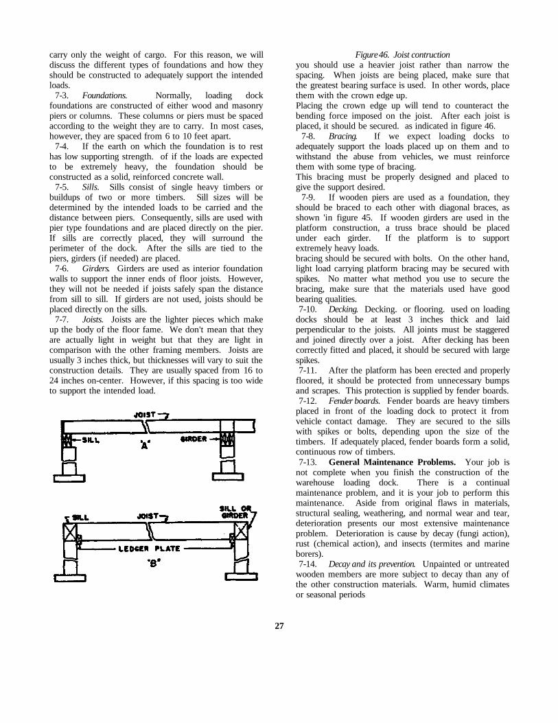
carry only the weight of cargo. For this reason, we willdiscuss the different types of foundations and how theyshould be constructed to adequately support the intendedloads.
7-3. Foundations. Normally, loading dockfoundations are constructed of either wood and masonrypiers or columns. These columns or piers must be spacedaccording to the weight they are to carry. In most cases,however, they are spaced from 6 to 10 feet apart.
7-4. If the earth on which the foundation is to resthas low supporting strength. of if the loads are expectedto be extremely heavy, the foundation should beconstructed as a solid, reinforced concrete wall.
7-5. Sills. Sills consist of single heavy timbers orbuildups of two or more timbers. Sill sizes will bedetermined by the intended loads to be carried and thedistance between piers. Consequently, sills are used withpier type foundations and are placed directly on the pier.If sills are correctly placed, they will surround theperimeter of the dock. After the sills are tied to thepiers, girders (if needed) are placed.
7-6. Girders. Girders are used as interior foundationwalls to support the inner ends of floor joists. However,they will not be needed if joists safely span the distancefrom sill to sill. If girders are not used, joists should beplaced directly on the sills.
7-7. Joists. Joists are the lighter pieces which makeup the body of the floor fame. We don't mean that theyare actually light in weight but that they are light incomparison with the other framing members. Joists areusually 3 inches thick, but thicknesses will vary to suit theconstruction details. They are usually spaced from 16 to24 inches on-center. However, if this spacing is too wideto support the intended load.
Figure 46. Joist contructionyou should use a heavier joist rather than narrow thespacing. When joists are being placed, make sure thatthe greatest bearing surface is used. In other words, placethem with the crown edge up.Placing the crown edge up will tend to counteract thebending force imposed on the joist. After each joist isplaced, it should be secured. as indicated in figure 46.
7-8. Bracing. If we expect loading docks toadequately support the loads placed up on them and towithstand the abuse from vehicles, we must reinforcethem with some type of bracing.This bracing must be properly designed and placed togive the support desired.
7-9. If wooden piers are used as a foundation, theyshould be braced to each other with diagonal braces, asshown 'in figure 45. If wooden girders are used in theplatform construction, a truss brace should be placedunder each girder. If the platform is to supportextremely heavy loads.bracing should be secured with bolts. On the other hand,light load carrying platform bracing may be secured withspikes. No matter what method you use to secure thebracing, make sure that the materials used have goodbearing qualities.7-10. Decking. Decking. or flooring. used on loading
docks should be at least 3 inches thick and laidperpendicular to the joists. All joints must be staggeredand joined directly over a joist. After decking has beencorrectly fitted and placed, it should be secured with largespikes.7-11. After the platform has been erected and properly
floored, it should be protected from unnecessary bumpsand scrapes. This protection is supplied by fender boards.7-12. Fender boards. Fender boards are heavy timbers
placed in front of the loading dock to protect it fromvehicle contact damage. They are secured to the sillswith spikes or bolts, depending upon the size of thetimbers. If adequately placed, fender boards form a solid,continuous row of timbers.7-13. General Maintenance Problems. Your job is
not complete when you finish the construction of thewarehouse loading dock. There is a continualmaintenance problem, and it is your job to perform thismaintenance. Aside from original flaws in materials,structural sealing, weathering, and normal wear and tear,deterioration presents our most extensive maintenanceproblem. Deterioration is cause by decay (fungi action),rust (chemical action), and insects (termites and marineborers).7-14. Decay and its prevention. Unpainted or untreated
wooden members are more subject to decay than any ofthe other construction materials. Warm, humid climatesor seasonal periods
27

of high humidity (moisture content) provide excellentconditions for the growth of decay-causing fungi.Wooden members which are near, touching or set indamp ground are especially subjected to fungi growth.To prevent or minimize this fungi growth is our job if weexpect maximum service from our wooden structures.7-15. Exposed wooden members should be panted or
soaked with creosote Whenever possible, woodenmembers should be constructed on some type of masonryfoundation and above ground level. This holds true fortreated as well as untreated timber.7-16. Rust and its prevention. Iron and steel
components will rust after prolonged periods of exposureto rainfall, snow, or moisture-laden air.This is particularly true If the metals are not painted orotherwise treated against this type of reaction. Paintmetals which are not inherently resistant or otherwiseprotected from rust.7-17. Insects and their elimination. Where wooden
structures are concerned, termites present a majorinspection and repair problem. If these insects establishthemselves in or beneath a structure, they constructearthlike shelter tubes which lead to the wood portion ofthe structure. These tubes may enter the wood frombelow or through cracks between brick or hollow tile.A well-established termite colony can cause majorstructural damage in a very short while. For this reason,we must provide an adequate insect control program.7-18. Some of the basic methods used to discourage
termite infiltration are soil treatment, wood treatment,termite shields, not allowing wood to come in contactwith the ground, and preservative treatment of supportingwood piles. Special detail in foundation construction willalso discourage termite activity. However, if termitecolonies do accumulate, consult your entomologist.7-19. Corrective Repairs. These maintenance problems
can and do create serious situations; however, if they areadequately approached and treated, the seriousness will bereduced. Proper inspection and maintenance methodswill prolong the useful life of all structures.7-20. To determine the best repair method depends
upon the use of the structure, extent of damage, lifeexpectancy, and its possible future use. These are veryimportant factors, but why repair are needed is alsoimportant. The extent of damage will depend upon whyor how the structure failed. To determine this we mustknow the causes for failure.7-21. Premature failure of materials and various
components may be caused by one of the followingreasons:
a. Defective materials or structural components.
b. Incorrect installation or application.c. Failure of related, connected, or adjacent
component.d. Faulty design.e. Unusual or extreme climatic conditions,
exceeding the design specifications for which thematerial or structural part was de.
signed.f. Use exceeding the limitations of original de sign.g. Use other than that for which the structure was
designed.7-22. If failures occur during the normal life
expectancy of the structure, they should be carefullyinvestigated and the defects corrected before anysuperficial repair is done. Unless the causes of thesefailures are identifiable or corrective procedures arestandard, the installations engineer should be consulted radequate corrective measures.
8. Waterfront Structures
8-1. The fundamental principles and practicespresented here are meant to assist you in the preservationof waterfront structures in the most economical manner.These fundamentals are intended to insure that facilitiesare maintained in such a condition that they can be usedthroughout their planned life. These structures would bemaintained by an Army carpenter, if that carpenter wasassigned to one of the waterfront installations maintainedby the Army.
8-2 If a carpenter is expected to maintain waterfrontstructures, he must know what these structures are, theterms used in working with them, what damages them,the preventive maintenance methods, and the inspectionand repair procedures used in conjunction with them.Let's discuss these methods and procedures.
8-3. Generally speaking, waterfront structures includewharves, quays, pier bulkheads, retaining walls,breakwaters, jetties, groins, and other supporting features.However, wharves, quays, piers bulkheads, and retainingwalls are the only structure that we will be working with;so we will center our discussions around them. Thissection covers the construction features, special toolsneeded, general maintenance problems, corrective repairs,preventive maintenance measures, and safety measuresfor waterfront structures.
8-4. Wharves and quays are structures constructedparallel or approximately parallel to the shoreline whichprovide berthing or docking for seagoing vessels. Thesestructures are virtually
28

the same and, from this point, will be referred to aswharves.
8-5. Piers are structures constructed perpendicular orapproximately perpendicular to the shoreline whichprovide berths and slips to tie up, or moor, vessels oneither side.
8-6 Bulkheads and retaining walls are structuresconstructed approximately parallel to the shore to protectthe shore from soil erosion.
8-7. Wharves and pier must be maintained to theextent necessary to insure safe and efficient use forberthing, servicing, repairing, and overhauling seagoingvessels. The principal jobs of maintaining thesestructures are as follows:
a. Replacement of broken or damaged fender piles.b. Replacement of deteriorated wood decks and
stringers and other timbers affected by attacks ofmarine borers.
c. Replacement of corroded and deteriorated pipe.d. Removing scale and repainting steel member.e. Repairs to pavement deck surfacing.
8-8. There are several terms specifically applicable tothe maintenance and repair of waterfront structures andharbor facilities. Some of these terms and theirdefinitions are as follows:
BITT--A double post to which vessels are moored, ortied.
BOLLARD--A single post to which vessels are moored,or tied.
CHOCK--A block with two horn-shaped convergingarms used t guide lines. It is sometimes called a fairlead.A chock is also considered a horizontal timber fittedbetween two vertical fender or fender piles.
CLEAT--A horizontal device with two diverging armsto which mooring lines from vessels are fastened.
DOCKS--Sheltered basins in which vessels are berthedor docked.
DOLPHIN--Usually a cluster of piles placed in thewater for mooring vessels or keeping them away fromstructures, shoals, or shores.
FENDER--A structural feature used to lessen the shockor minimize the damage when vessels come in contactwith shore structures.
MOORING--Facilities to which vessels are safelysecured. They include mooring platforms or islands,dolphins, piers, wharves, etc.
PIERHEAD LINE--An established harbor line markingthe permissible limit of pier construction. This is usuallylimited to open type construction.
QUAY WALL--A wall along the shore to retain thesoil. It may be used as a wharf: however.
when used as a wharf. it becomes a quay. or marginalwharf.
SEAWALL--A wall along the shore to preventencroachment (enter by gradual steps) by the sea. But ifthe wall is used as a wharf, it is not called a seawall.
SLIP-The area between two piers.8-9. Wharves and piers are constructed from timber.
concrete, steel, or a combination of these materials.Usually, timber is the most widely used, because it ismore economical, lighter, and easier to work. However,the serviceable life of timber is shorter than the others,because it is subject to decay by fungi action anddeterioration by insect infestation. Its life can beextended by protecting it with a preservative. For themost part, creosote treatments are very effective againstthese actions.8-10. Before any waterfront structure is constructed,
there are many factors to be considered. Among thesefactors are:
a. The sizes of vessels to be accommodated.b. The amount of cargo to be handled.c. The loads (dead and live) to be carried on the
structure.d. The depth of the water.e. The variations in tide.
8-11. Construction Features. To make sure that ourwharf or pier can absorb the abuse, we must use the typeof construction components recommended.8-12. Pilings. There are three types of piles used for
wharf and pier construction: bearing pile, fender pile, andmooring pile. If timber is used as piling, it must betreated with creosote or some other preservativecompound to protect it from fungi and marine borerattacks.8-13. Bearing piles support the wharf or pier
framework and decking. The piles should be straight andmeasure at least 6 inches across the top, 18 inches acrossthe butt (bottom), and from 60 to 80 feet in length. Thelength varies according to the depth of the water andcondition of the bottom. These bearing pies should bespaced from 6 to 10 feet apart, center to center, in onedirection and 5 feet apart, center to center, in the otherdirection.8-14. The force of a moving ship (coming in direct
contact with bearing piles) is sufficient to collapse awharf it the pilings are not protected. To furnish thisprotection and to absorb the initial shock, fender piles areplaced approximately 2 1/4 feet out from the centerlineof the outside row of bearing piles. These piles areplaced approximately 18 feet apart and along the sideswhere the ships dock.
29
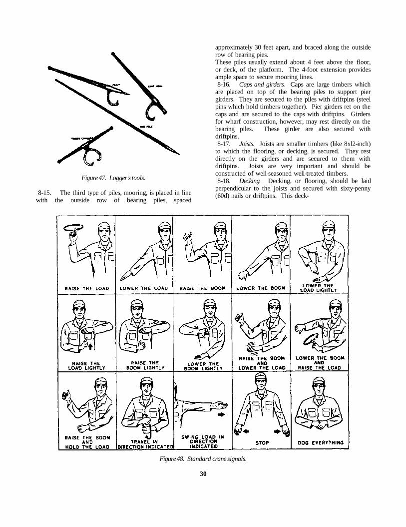
Figure 47. Logger's tools.
8-15. The third type of piles, mooring, is placed in linewith the outside row of bearing piles, spaced
approximately 30 feet apart, and braced along the outsiderow of bearing pies.These piles usually extend about 4 feet above the floor,or deck, of the platform. The 4-foot extension providesample space to secure mooring lines.8-16. Caps and girders. Caps are large timbers which
are placed on top of the bearing piles to support piergirders. They are secured to the piles with driftpins (steelpins which hold timbers together). Pier girders ret on thecaps and are secured to the caps with driftpins. Girdersfor wharf construction, however, may rest directly on thebearing piles. These girder are also secured withdriftpins.8-17. Joists. Joists are smaller timbers (like 8xl2-inch)
to which the flooring, or decking, is secured. They restdirectly on the girders and are secured to them withdriftpins. Joists are very important and should beconstructed of well-seasoned well-treated timbers.8-18. Decking. Decking, or flooring, should be laid
perpendicular to the joists and secured with sixty-penny(60d) nails or driftpins. This deck-
Figure 48. Standard crane signals.
30

ing should be at least 3 inches thick and joined directlyover the joist. The joints should be staggered for greaterstrength and support.8-19. Special Tools Needed. Since you cannot
manhandle all of the heavy timbers you will be using tobuild waterfront structure, special tool are used to moveand place these timbers. They are known as logger'stools and consist of peavys, cant hooks, timber carriers,and pike poles. The peavy and cant hook are lever typetools and are primarily used to roll timbers Timbercarriers are considered two-man tools; they are primarilyused to pick up and/or carry timbers. Pike pole are usedto hold or steady timbers while they are being placed.These tools are shown in figure 47. Although the canecannot be considered a special tool, we include it herebecause it is used to raise and lower heavy timbers, suchas are used in the building of waterfront structures.Normally, two men are assigned to the crane: theoperator, and the helper. The helper drives the cranecarrier (truck), hooks and unhooks loads, and signals theoperator when to lift and lower the load and where toposition the load. Standard signals are used for thesepurposes. You will not be called upon to operate thecrane; but there will be times when the crane helper isnot available, and at such times you will probably have tohelp the crane operator with the signals. You willprobably be working with the standard crane signals,illustrated in figure 48. Study and learn the signalsthoroughly, because f you give the crane operator anincorrect signal, it could cause an accident that woulddamage some very expensive equipment. Remember,after the heavy timbers have been moved and placed,they must be leveled properly. The carpenter's level,which you learned about in Memorandum 531, is the toolused for this purpose.8-20. Let's assume that you are going to remove and
replace some damaged wooden pier component. Beforeyou can replace the component, you must prepare themby boring boltholes, notching for special fits, etc. Also,you must know and use certain types of timbers,equipment and specifications. What are some of thesethings you should know? 8-21. These items of information are called General
Notes and are found on the construction plan. Theyshould be used any time you construct a new structure orrepair an existing one.From these notes you will get such information as thesize hole to drill for driftpins and bolts, how bolts shouldbe placed, basis of design, type of hardware to use, etcLet's take a look at a sample General Notes legend.
General Notes
Holes for driftpins (D.P.) shall be 1/16” smaller than thepin itself.
Holes for through bolts shall be the same diameter as thebolt itself.
No bolthead should project beyond face of timber onoutside face of fender system.
All piles must be creosoted if they are to be used wheremarine borers are active.
All lumber must be rough except 4” plank decking, whichshall be finished on wearing side only.
Basis of design:Live load--500# per sq. ft.Pile bearing value--50,000#Gantry crane--17-ton capacity.Extreme fiber stresses--wood, 1800# per sq. in.Compression parallel to grain--wood, 1500# per sq. in.Compression perpendicular to grain--wood, 450# per sq.
in.Horizontal shear--wood, 15-# per sq. in.Modulus of elasticity--wood, 1,600,00.
Use O.G. cast iron washers with all bolts.The length of pile as listed in “Bill of Material”assumes a penetration of 15’. The penetration requiredshould be determined by driving tests and the length ofpiles adjusted accordingly. Projecting ends of all bolts should be peened after nutsare tightly drawn.
8-22. Let's take a look at some of the problems ofgeneral maintenance of waterfront structures with whichthose, like you, in the specialized carpentry field shouldbe familiar. To begin with, what are the primary causesof pier or wharf construction failures? 8-23. General Maintenance Problems. Chief among
the general maintenance problems resulting from pier orwharf construction failure are the same causative factorsas those that damage warehouse loading docks. To thesecan be added storms, collisions, and marine borers.8-24. Deterioration is also responsible for some pier
and wharf failures. This deterioration may be anticipatedand corrected as outlined below. It is caused by decayand the action of termites and marine borers. Decay,turn, caused by the action of low parasitic forms of plantlife known as fungi. The growth of these fungi dependupon moisture, food, air, and temperature (warmth).Consequently, the absence of any one of theserequirements will prevent fungi growth. However, themost general and successful way to stop fungi growth isto poison the food supply We usually poison the foodsupply by treating the timber itself with creosote.8-25. Termite attacks on structural building timbers
are probably the chief causes of insect damage. This isspecifically true of timber components which are in directcontact with the earth. Although termite are the chiefcauses of damage, they are not the only damaging insects.
31

Marine borers are also responsible for some of thedeterioration actions on timbers.8-26. There are many types of marine borers, but only
two general groups (mollusks and crustaceans) areimportant to us now. Borers belonging to the mollusksgroup enter the timber, burrow themselves, andhoneycomb the interior. On the other hand, thecrustaceans operate by forming shallow gullies just underthe surface.8-27. Wharf or pier construction failures are caused
either by mechanical factors or by deterioration factors.No matter which is responsible, the damage must berepaired So lets take a look at some of the correctiverepairs which can be made and try to determine whichmethod we should use to repair any particular damagedpier.8-28. Corrective Repairs. Wharves and piers are
usually repaired by replacing the damaged part. Thereplacement part should be of the same type of materialas the part it is to replace. But, if failure is due tooverloading and if it is believed that overloading willrecur, the structure should be reinforced or otherwisestrengthened.8-29. Failures by deterioration are the hardest to
detect and correct. Failure to correctly estimate how farrepairs should be carried out is one of our biggest errors.This is specifically true if the failure is due todeterioration. From a visual inspection, some timberslook solid and sound; but when removed, they may befound to be hollow shells. This is primarily due toattacks by termites. Similarly, fender pile which aresound above the water line are often damaged near theground line by marine borers. For these reasons, alltimbers must be carefully checked to determine their truecondition. Two ways to do this are to hammer ontimbers or t drive nail into them to see whether theyhave become softened by deterioration. If you havedoubt as to the soundness of a structure, you should boreholes into the sides of caps and stringers. If you find thetimber to be sound, carefully plug and paint the holes tokeep out further moisture.8-30. Generally speaking, the materials used for repairs
or replacements should be of the same type and size asthose used in the original design. However, no matterwhat type of materials are used, you must handle themwith care if you intend to get maximum service. Also, tostop the entrance of fungi and insect, you must re-treatall low-resistant areas and broken surfaces of treatedtimbers. If cu are made in the surface of treated timbers,you should paint them with two or more coats ofpreservative compound. Now, if creosote is used for this
treatment, it must be applied at some temperaturebetween 175° And 200° Fahrenheit. Another thing toremember is to avoid the use of timber hooks, canthooks, or other sharp-pointed tools when you are handingtreated timbers.8-31. Most of our modern treatment plants precut
timbers to size and notch and bore them beforetreatment. This prevent the need for further treatment ifyou handle these timbers with care.8-32. So far, we have discussed the construction
features of wharves, piers, and quays; the special toolsneeded for such work; the general maintenance problemsinvolved here; and the corrective repairs necessary. Nowlet's talk about some of the ways to prevent or minimizedamage to these structures and safety measures whichyou use in such work.8-33. Preventive Maintenance Measures. To
adequately maintain wharves and piers, we must provideand maintain an appropriate preventive maintenanceprogram. This program must outline preventive measuresand present specific frequencies for inspections andcorrective actions. Therefore, we are going to discuss themethods you should use to maintain these structures. Aswe have explained above, wharf and per structures aredamaged from wear, deterioration, insect infestation,overloading, storm damage, fire, etc However, thedamaging effect from these factors can be minimized ifwe follow the procedures and precautions outlined in thefollowing paragraphs.8-34. To guard against excessive wear to decking, we
must make frequent inspections and keep tracked vehiclesor other iron wheeled equipment from traveling over itPost notices of this restriction in conspicuous places. Allloose bolts and nuts found during the inspection shouldbe tightened. All decking should be securely nailed atevery joist. If decking is 3 inches thick, 60d nails or 6-inch spikes should be used. If it is 4 inches thick, 7-or 8-inch spikes should be used. All planking used as deckingmaterial should be of the same thickness to give asmooth surface.8-35. Fender piles should be removed and replaced
before excessive wear occurs. Normally, only hardwoods(such as oak) are used for fender piles; however, if trafficis light, creosoted softwood piles may be used. Nomatter what type wood is used, make sure that all chocksare tightly fitted between the piles. These chocks helpprevent the piles from rolling when rubbed by vessels. Ifcurrents are swift, fender log should be used to preventdamage to piles. Also, a thorough check of all timberand hardware should be made and any necessarycorrective actions taken.
32

8-36. If fender piles should break. serious damage canbe done to the structure by the impact of vessels;therefore, all fender piles should be replaced at regularintervals.8-37. The anticipated normal life of fender piles will
vary in different localities, depending upon the type ofpile, water and soil conditions and other factors.Anticipated normal life can be established withreasonable accuracy after a few years or by observingother similar structures in the vicinity. After theanticipated normal life has been established, everyreplacement pile should be numbered and a historicalrecord kept on it to make sure that it is replaced beforethe end of its anticipated life.8-38. Safety Measures. When any type of work is
performed on a wharf or pier structure, the followingsafety precautions should be observed:
• Make sure all safety provisions arc applied whenladders, runways, platforms, scaffolds, and guardrails areused.
• See that all equipment is inspected by some qualifiedperson and is found in safe operating condition before itis used.
• Don't permit workmen to ride loads, hooks,hammers, material hoists, buckets, or any type of movingequipment.
• Don't allow loads, booms, or buckets to be swungover the heads of workmen.
• Require all workmen to wear life vests when they areworking over water, unless proper scaffolds, platformswith guardrails, or safety belts and life lines arc provided.
• Insist that workmen wear protective clothing, goggles,or other safety equipment required by the type of workbeing done.
• Make sure that all provisions covering storage ofmaterials and disposal of waste are adequately followed.
33

CHAPTER 4
Sawmill Operation
THE NUMBER Of Army people serving in Vietnam hasincreased tremendously since 1965. As a result, facilitiesconstruction--quarters, offices, depot, hangars, etc.-hasbeen a major problem. It is your job to relieve this andsimilar problems, because as an Army carpenter, you willbe building the facilities needed.
2. It take much hard work to build a building whenthe lumber is available. In your job in the Army, inplaces like Vietnam, there will probably be times whenthe lumber is not available. If you run into this situation,your job will be twice as difficult, because you will haveto go into the jungle and cut the lumber. For you to beable to do this job, you must know how to erect andoperate a sawmill.
3. This chapter discusses erecting sawmill, buildinglog skidways, operating sawmills, and caring for largecutting saws. It also discusses the important rules insawmill operation.
9. Erecting the Sawmill
9-1. Most of your sawmill work in the Army willprobably be performed with a portable sawmill. One ofthe many different types of portable sawmills is shown infigure 49. Usually, a portable sawmill is erected (set up)once a day and it very seldom remains at one setup over2 days. It is preferable to move the sawmill away fromthe material accumulated rather than to move thelumber, slabs (the outside pieces, with or without thebark, taken from logs in sawing them into boards), andsawdust. On large setups the sawmill is simply movedahead progressively to other skidways and away from theaccumulated material. After you set up a sawmill two orthree times, you should be able to set it up in a shortlength of time.
9.2. To erect the main frame of the sawmill, place itwithin a few feet of the location where you intend tooperate it. Then you can prepare the exact location andmove the mill the few feet into place. If the sawmill ismounted on pneumatic tires, dig a shallow trench in
front of each wheel on level ground. This is done sothat when the sawmill is leveled up, some of its weightwill be removed from the tires. If this is not done, thesawmill will not sit rigidly enough. Pull the sawmillahead to fit into the trenches. Be sure that the sawdustconveyor does not rest on the ground when the sawmillis pulled into the trenches. Unhitch the truck or powerunit from the sawmill and place it in a relative position tothe sawmill that will let you align the drive belt from thepower unit to the sawmill.
9-3. Leveling. The sawmill must be leveled properly,If it is not level, the saw will run "in' or "out at the front.A saw that runs "in" at the front will make the last pieceof lumber cut (the dog board) thin at the top. A sawthat runs "out" at the front will make the dog board thickat the top. In other words, the lumber will not be square.When you level the sawmill, be sure that some material,such as a plank or timber, is placed on the groundunderneath each leg to prevent it from settling into thesoil as the operations proceed. To level the sawmillproperly, you must consult the operator's manual for theparticular make and model you are using.
9-4. Bracing. After you have leveled the sawmillcorrectly, brace it securely to compensate for drive belttension. Most portable sawmills are braced by securing abrace against the frame of the sawmill and to the groundor power unit. In addition to bracing the sawmill, youmust also set up the sawdust conveyor chain and anchorit. On most sawmills, this chain is anchored by drivingan iron pipe or strong pole into the ground. To brace thesawmill properly and to anchor the sawdust conveyorchain, you must also consult the operator's manual forthe particular make and model you are using.
10. Building Log Skidways
10-1. Before you erect the sawmill, you should line upyour sawing sites before you start sawing the lumber.This is done to determine the exact
34

Figure 49. Portable sawmill.
location of the logs, to ascertain the accessibility by truck,and to check the skidway. A skidway is a platform madeof skids on which logs are piled for loading. If possible,skidways should be made on a gentle slope where there isenough space to pile lumber, slabs, and sawdust. Askidway is shown in figure 50. Skidways are installed ongentle slopes so that the lumber and slabs are carrieddowngrade. This procedure decreases the labor involvedtremendously. It is also advantageous to have logs piledon one rollway, because most portable sawmill carriagesare not equipped to take on logs from two rollways. Logsare usually received on the carriage with the butt-endtoward the saw.10-2. Sometimes a tractor with a fingerlift can be used
to great advantage with a portable sawmill. It can beused to load and even turn large logs at the skidway, andload lumber on trucks. In large commercial operations,or where the timber stands are thick and the logs large,portable sawmills can be used in pairs. A tractor with afingerlift can be kept busy at the skidways, at the slabpiles, and loading lumber at the trucks. This is a goodmethod to use when you are short of personnel, becausethe need for quite a few men can be eliminated by thismethod.
11. Operating the Sawmill
11-1. Now that you have erected the sawmill and havebuilt the log skidway, you are ready to operate the mill.But before you attempt to operate the sawmill, youshould acquaint yourself with the operator's or sawyer'sposition and stance on the carriage. This familiarizationwill give you the feel of the moving carriage and allowyou to make the movements most natural to you.11-2. You must also acquaint yourself with the relative
dimensions of the sawmill carriage. Give specialattention to the length and distance between the headblocks (blocks under the head of the log to raise it),because this information will help you position thecarriage properly to receive the log that is approaching onthe skidway. This positioning of the log on the carriagecannot be overemphasized. No set rule can be given,because all logs are different, but you should always striveto work with the center of the log in the center of thecarriage. You will feed the saw from the operator'sposition on the carriage. The carriage moves forward andbackward past the
35

saw. On the forward movement, the log directed intothe saw to cut the board from the side of the log.11-3. As the log is being brought up in readiness to be
placed on the carriage, you must consider the presence ofextending knots or other obstructions that could preventthe log from lying firmly on the carriage or obstruct itpas age as the carriage is brought forward.11-4. You must also consider any bends in the log.
The tendency for a new operator is to place the bow or"belly" of the log up or down. In fact, many old sawyerswant the bow up and slightly out. It has been found bycareful check as to the quality of lumber produced, thatthis procedure b definitely wrong. The correct position iswith the bow of the log on a horizontal plane toward theoperator’s side to the carriage, and the log resting on allthe head blocks over which it extends.11-5. In this position, the log can easily be brought out
on either end by use of a wedge or pried out with a canthook so that the line of cut will be equal on each end.11-6. Logs should be received on the carriage with the
butt-ends (large ends) toward the saw, especially longlogs, because the heavy butt on the overhanging end will
have a tendency to tip the carriage up. Also, the saw isnow apt to run "out", that is, to follow the grain of thewood.11-7. After the log is received on the carriage, it must
be dogged. "Dogging" is the term given to the act ofsecuring the log on the carriage by hooking the dogs intothe log This very important, because improperly doggedlogs or cant my result in accidents and usually result indamage to the saw, which in turn means lose of time andmanpower.11-8. The following hand tools are considered
essential to the operation of a portable sawmill unit:
a. Axeb. Shovelc. Oil cand. Cant hooke. Spirit levelf. 8-inch half-round Aleg. Saw Aleh. 8-inch adjustable jaw wrench
Figure 50. Skidway.
36

i. 10-inch adjustable jaw wrenchj. Additional tools for the power unit
12. Caring for the Saw
12-1. Your job is not complete when you finishsawing the lumber. You must take care of the saw. It isimpossible to place enough emphasis on taking care ofthe saw. It can truthfully be said that it is the mostimportant part of any type of machine which convertslogs into lumber, whether it be a stationary or a portablesawmill. If you do not take care of your saw, it can slashyour production, ruin the accuracy of the dimensions ifthe lumber, and leave you in the depths of despair.12-2. There is nothing on the sawmill that takes as
much abuse as the saw. For instance, should a log comeloose from the dogs while this tremendous strain is onthe saw, it will very likely kink (bend) it, bringing a haltto operations and resulting in loss of time and manpower.All saws vary considerably and require different methodsof handling. This is partly due to the hardness ormildness (softness) of the steel from which they aremade.12-3. Teeth. A new saw will always run well for a
few hours. It may make a rather rough cut, but it willalways run a few hours if the saw is tensioned for theproper speed and the natural lead is properly set. Thesefacts assure you that, if the teeth can be kept properlysharpened (like new teeth), the saw will continue to runand cut in a true line. Therefore, when you find that itdoes not do this, the deviation usually indicates that thesaw teeth have not been sharpened properly. It has beenproven that if an improperly sharpened saw is too long itwill lose the proper tension and may cause blisters todevelop on the saw blade. If this happens, you will haveto have a competent saw expert retension the saw byhammering it. Hammering a saw is an art and shouldunder no circumstances be attempted by anyone withlimited experience. When your saw ceases to cutproperly, stop your operations and sharpen it.12-4. Blade. Most of your sawing will be done with a
chisel tooth. So let's find out how a chisel tooth sawworks. Many saws used to cut wood lengthwise of thegrain are swedge-set chisel tooth saws. Many saws usedto cut crosswise of the grain are spring-set pointed toothsaws. A spring-set cutoff saw cuts the sides free andtears out the portion between the two edges that are cutfree by the sharp points. Therefore, as soon as the pointbecome dull and do not cut the edges free, furthersawing is difficult, and the saw is said to be dull.Sharpening the points will correct this situation and youcan resume your work. Inasmuch as the center is tornout, any alight increase in the kerf (cut or stroke) will
increase the amount to be torn out and will increase thepower accordingly.12-5. A rip chisel tooth saw cuts across the center and
tears out the two corners. For this reason, the width ofthe cut or stroke does not materially affect the powerrequired The two edges have to be torn free, regardlessof how narrow the cut or stroke is, and this is whatconsumes the power. Notice the chisel tooth shown infigure 51. The corners of the tooth do the tearing.Therefore, the things that lessen the tearing effect of thecorners will affect the power consumption immediatelyand cause a corresponding increase in the power usedthrough each tooth. This can cause much trouble.Therefore, the condition of the corners of the teeth is ofgreat importance.12-6. In addition, if one corner of the tooth becomes
duller than the other, the one causing the greaterresistance will have a tendency to force the saw theopposite way, which will cause the side of the saw to rubon the side of the log. If the saw rubs on the side of thelog, it will do one of two things: (1) If the log is movingendways slowly, and if the saw is rotating as it rubs theslowly moving log, it will generate heat in the saw whichwill cause the metal to expand. This, in turn, will causethe saw to lose the stiffness required to run straight Thefurther this condition is allowed to develop, the moredifficult it becomes to remedy. (2) On the other hand, ifthe log is passing the saw at a higher rate of speed, thesaw will have a tendency to cool as it rubs against thelog, because the inside of the
Figure 51. Chisel tooth.
37

log is cool. This will cause the metal to shrink andstiffen.12-7. Another factor that will affect the operation of
the saw is an improper angle on the front of the tooth.This will us the saw to run "in" or "out." Remember,the cutting edge of the saw should be straight across.12-8. Speed. Usually, the speed of a portable sawmill
is the greatest that can be maintained both in and out ofthe cut. A usual mistake of operators is to try to operatethe saw at too great a speed. A regular uniform speedboth in and out of the cut insures more lumber and moreaccurate lumber. The speed should be governed by theavailable horsepower, of course, and must be increased asthe power to drive the saw is increased.
13. Basic Rules In Sawmill Operation
13-1. There are many basic rules that are important insawmill operation. These rules apply to greasing the saw,handling the saw, and checking the carriage.13-2. Greasing. While greasing the sawmill, do as
follows:a. Apply heavy oil to the gears of the sawdust
conveyor twice daily b. Use soft, light pressuregun grease.
c. Use only pressure gun grease in grease gun.d. Lubricate the knee slides and gear rack slides
and other moving parts frequently with lightmachine oil. Some sawmill operators make a
practice of lubricating the surface of the kneeson which the log rests when they are taking on alarge log because it helps in turning the log.Some operators use powdered graphite on thehead block slides instead of oil.
e. Remove all bearings on which the carriage slidesand wash them out with solvent and repackthem with pressure gun grease once a year.
13-3. Saw. In handling the saw, always observe thefollowing rules:
a. Don't ever saw with a “hot” saw.b. Never saw with dull teeth.c. Don't allow chips to rub the saw.d. Keep the saw clean of pitch. (NOTE: Pitch
sticks only to a hot saw.) 13-4. Carriage. When checking the carriage, proceed
as follows:a. Be sure that the carriage is level.b. Always check the carriage before you start
sawing by running it up and down the track two or threetime to determine whether the ropes are in order and thesaw is in the clear.
c. Always check the dogs when you are not sawing,especially on the "return" after the last board is cut fromthe log. Keep the dogs away from the saw.
d. Always keep the saw guides adjusted properly.e. Always lock the carriage when you complete the
day's work or whenever the machine is not in operation.f. Always put in the carriage bolt and lockpin and
set the hand brake when you are going to move the mill.
38

CORRESPONDENCE COURSE OFU. S. ARMY ENGINEER SCHOOL
SUBCOURSE 0533.................................................................................Carpentry III (Specialized Carpentry).LESSON 1...............................................................................................Cabinetwork.
SOLUTIONS
All references are to Memorandum 0533.
1. c (par 1-7)2. a (par 2-11)3. b (par 2-13)4. a (par 2-17b)5. b (par 3-8)6. d (par 1-12)7. a (par 2-14)8. d (par 2-18)9. a (par 3-15)
10. c (par 1-8)
11. a (par 3-29)12. b (par 1-14)13. b (par 2-15)14. c (par 2-22)15. d (par 1-6)16. d (par 1-7)17. c (par 1-1)18. a (par 2-17)19. b (par 2-16)20. c (pars 3-7, 3-8)
For further explanation, see Discussion.
1-1

DISCUSSION
Exercise:
1. Cedar (c) has a high resistance to decay. It is used as a liner for closets, cedar chests, etc., because of its mothrepellant action.
2. Lap (a) joints are used by the carpenter or cabinetmaker to connect crossrails to the sides of cabinets.
3. Dado (b) joints are actually grooved joints with the groove running across the grain of the wood. They are usedextensively in cabinet-drawer construction.
4. For rough knockdown or outside furniture, the tenon can be cut longer than the depth of the mortise, with a holedriven in the protruding part. This is called keyed mortise and tenon (a) joint.
5. Stool (b) construction is really four frames put together to form a rectangle or square. It is used for tables, chairsand stands.
6. When quartersawed, the medullary rays of oak (d) grain are broad and numerous, making pleasing patterns.
7. Grooved (a) joints have the groove, or plow as it s sometimes called, running with the grain of the wood. Theyare used extensively in panel construction.
8 To determine the proper thickness of a tenon, compare it with the member of which it will be a part. The tenonthickness should be about one-third the thickness (d) of the member.
9. Often tops are large enough to require two or more pieces to be glued together. The method of fastening them tothe furniture is important because of the swelling and shrinking (a) of tops.
10. Redwood (c) holds paint exceptionally well, shrinks very little, and keeps its shape. It is used for garden furniture.These qualities make it best choice for the exposed locations of the shuttle bus stops.
11. Before you assemble the unit into final form, you must make a preassembly check by checking each piece fordimensions, shape, and fit (a).
12. Hardwood is graded as follows: first (b), second, select, No. 1 common, No. 2 common, and No. 3 common.
13. The miter (b) joint can be fastened with glue and metal fasteners. It is a diagonal joint and it is used extensivelyfor frames and moldings.
14. The size of the dowel should be large enough to support the intended job without weakening it. The diametershould be approximately one-third to 1 (c) the thickness of the stock on which it is being used.
1-2

15. Fir (d) is difficult to work with hand tool, but it glues well. It is used extensively in millwork and boatbuilding.
16. Cedar (d) has the qualities listed in the stem of the exercise. In addition, it works well, finishes smoothly, takespaint, and glues well.
17. In cabinetmaking, the desirable characteristics of wood are different from frame construction. For example, beautyand finishing qualities (c) would be determining factors rather than strength.
18. There are numerous variations of the mortise and tenon joint, providing ample choices for framing doors, panels,tables, chairs and cabinets. Open, through, blind, and haunched (a) are the four variations that should be recognized inthe exercise.
19. The splined (b) miter is a method used to reinforce a plain miter joint. Figure 5c is one way of inserting a spline.
20. The framework adds strength because wood grain runs lengthwise in both length and width. Frame construction ishighly desirable because it overcomes shrinkage and swelling (c) and provides ample strength for the panel. Stoolconstruction is subject to shrinkage.
1-3

CORRESPONDENCE COURSE OFU. S. ARMY ENGINEER SCHOOL
SUBCOURSE 0533.................................................................................Carpentry III (Specialized Carpentry).LESSON 2...............................................................................................Prefabricated Buildings.
SOLUTIONS
All references are to Memorandum 0533.
SOLUTIONS
All references are to Memorandum 0533.
1. c (par 4-18)2. a (par 4-23)3. c (par 5-19)4. a (par 6-4)5. b (par 5-26)6. c (par 4-12)7. d (par 5-10)8. a (par 5-31)9. c (pars 5-4, 5-2)
10. b (pars 5-14, 5-16)
11. b (par 5-14)12. c (par 5-2)13. a (par 5-1)14. d (par 5-2)15. d (par 4-3)16. c (par 4-8)17. a (par 4-17)18. b (par 5-16)19. b (par 5-26)20. d (par 5-31)
For further explanation, see Discussion.
2-1

DISCUSSION
Exercise:
1. Tile and linoleum are not used on a wood floor if the floor is not reasonably solid and covered with a smoothunderlayment (c).
2. The rafter spacing is the same as stud spacing (a), 4-foot on center.
3. The lap joint and the vinyl seal joint are the two common methods used to make weatherproof vertical joints inexterior walls (c).
4. Two major modifications include the use of floors that are of double thickness and of walls and roofs that areinsulated (a). Heat is supplied by individual stoves or heaters.
5. The common metals used in construction are listed in the electromotive series in the following order: 1-aluminum(b), 2-zinc, 3-iron, 4-tin, 5-lead, 6-copper. When two of these are in contact the lowest number is corroded. The fartherthe separation in the list, the greater the corrosion.
6. Roof panels are built according to the climatic conditions that exist where the building is to be used. Insulatedpanels are used in both hot and cold (c) climates.
7. A bay is the distance between columns along the side walls (d). There is no limit to the number of bays that canbe placed end-to-end to form a building.
8. The glazing clip fits between the edge of the lass and the frame. One end fits into a hole in the frame and theother end hooks over the edge of the glass. The glass should be cut shorter than the sash by the thickness of two clips (b).
9. The standard size of the quonset hut is 20 x 48 feet. The floor is made of 4 x 8 foot sheets of plywood.
20 x 48 = 960’ area of floor4 x 8’ = 32’ area of plywood sheet960’ = 30 sheets plywood (c)32’
10. The brace rods between the roof beams serve to hold the bay square, and the sag rods (b) are used to prevent thegirts from sagging between the columns.
11. The sags rods are used to prevent the girts from sagging (b) between the columns. They are also used in the roofframe to hold the purlins line.
12. Nails, screws, and bolts (c) are used In the assembly of the quonset hut. These are easily removed when repair ordisassembly of the unit is required.
13. Prefabricated metal buildings are constructed of many types of metal, but galvanized sheet metal and aluminum (a)are the most common metals that are used in this construction.
2-2

14 The standard size is 20 x 48 feet (d), but there are some quonsets that are two or three times longer. They canbe assembled in 8-foot sections.
15. The joints between the panels are covered with the T-shaped metal strip, but when plywood is used for the floor,the edges and joints are protected by an H-shaped metal strip (d).
16. The wall panels are fastened in place with double-headed scaffold nails or bolts (c). The bolts fasten two panetogether along the vertical edge.
17. The floor consists of flooring, joists, and girders (a). Also, it may have a finish floor or the floor may be ofconcrete.
18. The brace rods are used to square the end bays (b) of the building. They run diagonally from the top of onecolumn to the bottom of the adjoining column.
19. When aluminum panel are placed on a steel frame a separator must be used because direct contact of the twometals results in corrosion (b).
20. The glazing clips (d) hold the glass in place while putty is applied. They fit between the edge of the glass and theframe. Use a screwdriver to install these clips.
2-3

CORRESPONDENCE COURSE OFU. S. ARMY ENGINEER SCHOOL
SUBCOURSE 0533.................................................................................Carpentry III (Specialized Carpentry).LESSON 1...............................................................................................Heavy Timber Contruction.
SOLUTIONS
All references are to Memorandum 0533.
1. d (par 8-13)2. c (par 8-18)3. b (par 8-34)4. a (par 8-19)5. a (par 8-24)6. b (par 8-16)7. a (par 8-16)8. a (par 8-13)9. a (par 8-13)
10. c (par 7-7)
11. c (par 7-18)12. a (par 8-9)13. b (par 8-5)14. b (par 7-3)15. d (par 8-4)16. d (par 8-9)17. a (par 8-14)18. b (par 8-19)19. a (par 8-13)20. d (par 8-15)
For further explanation, see Discussion.
3-1

DISCUSSION
Exercise:
1. These piles should be spaced 6 to 10 feet apart center-to-center in one direction, and 5 feet apart center-to-center in the other direction (d). Bearing piles support the wharf or pier framework or decking. The length variesaccording to the depth of the water.
2. The decking should be at least 3 (c) inches thick and joined directly over the joists. The joints should be staggeredfor greater strength.
3. If the decking is 3 inches thick, 60d nails or 6-inch (b) spikes should be used. If the decking is 4 inches, a 7- or 8-inch spike should be used.
4. Timber carriers (a) are considered two-man tools. They are primarily used to pick up and carry timber.
5. Decay is caused by the action of low parasitic forms of plant life known as fungi (a). This decay facilitates theaction of termites and marine borers.
6. Caps are large timbers which are placed on top of the bearing piles. Pier girders (b) rest on the caps and aresecured to the caps with drift pins.
7. In wharf construction, the girders may rest directly on the bearing pies (a). They would be secured with driftpins.
8. The bearing (a) piles support the pier framework and decking. They are spaced 6 to 10 feet apart in one directionand 5 feet apart in the other direction, all center-to-center.
9. The piles are 60 to 80 feet in length; the length varies according to the depth of the water and condition of thebottom (a).
10. Joists are usually spaced from 16-24 inches on center. If planned spacings may not support the intended load youshould use heavier joists rather than reduce the spacings (c).
11. Soil and wood treatment, termite shields, and preservative treatment are some of the methods used to discouragetermite infiltration, but if termite colonies still accumulate, consult your entomologist (c).
12. Usually timber (a) is the most widely used because it is more economical, lighter, and easier to work. Theserviceable life of timber, however, is shorter because it is subject to decay by fungi action.
13. Piers (b) are constructed perpendicular or approximately perpendicular to the shore line. Vessels can tie up oneither side.
14. Loading dock foundations in most cases are spaced from 6 to 10 feet (b) apart. They must be spaced according tothe weight they may carry.
3-2

15. Wharves and quays (d) are constructed parallel or approximately parallel to the shore line to provide berthing ordocking for seagoing vessels.
16. Timber (d) is more economical and easier to work. The serviceable life of timber is shorter, but its life can beextended by protecting the timber with a preservative.
17. To protect the pilings from direct contact with a moving ship, fender piles (a) are placed about 2 1/4 feet out fromthe center line of the outside row of the bearing piles.
18. Logger's tools are used to move and place heavy timbers. Pike poles (b) are used to hold or to steady timberswhile the timbers are being placed.
19. Bearing piles support the wharf or pier framework and decking (a). They should be straight and measure at least 6inches across the top and 18 inches across the bottom. The length is from 60 to 80 feet.
20. The mooring tiles are spaced approximately 30 (d) feet apart, and placed in line with the outside row of bearingpiles.
3-3

ARMY CORRESPONDENCE COURSE ENGINEER SUBCOURSE 0533-7
CARPENTRY III (Specialized Carpentry)
CREDIT HOURS....................................................................................11.
TEXT ASSIGNMENT............................................................................Review previous lessons.
EXERCISES
1. You are selecting wood to build a cabinet that will be painted. You have only hand tools. What kind of wood doyou select?
A. WalnutB. OakC. White pineD. Mahogany
2. Where would you use lap joints when making a cabinet?
A. in moldingsB. in panels of the doorC. in framework grooved for panelsD. to connect crossrails to sides of cabinet
3. How would you use dowel joints?
A. on moldings.B. for fastening cabinet drawersC. to reinforce butted boardsD. to strengthen frames.
4. You require two pieces of material that you will glue together for a cabinet top. What do you specify?
A. each piece same sizeB. pieces have equal weightsC. must have opposite grainsD. must have similar grains
5. In what direction would you sand a piece of wood used for a front on a cabinet drawer?
A. diagonally to the grainB. with the grainC. across the grain and perpendicular to itD. a scrubbing motion in all directions
EDITION 7

6. You have received detailed drawings and a blueprint for constructing desk drawers. When you start cutting the wood,how would you mark the pieces?
A. "sides", "fronts", "backs"B. "sides" (identified "left", "right"), fronts, backsC. 1, 2, 3, 4, 5D. sides, fronts, tops
7. You have received parts for a wooden article. They are supposed to have been milled to size, shaped, and sanded.You must now make a preassembly check of each part. What do you check first?
A. dimensionsB. shapeC. fitD. weight
8. What wood do you recommend for making fine furniture?
A. cedarB. redwoodC. mahoganyD. plywood
9. What is the spacing of the rafters in a framed prefab building?
A. 4-footB. 4-foot on centerC. 3-foot on centerD. 3-foot on edge
10. How far apart in feet do you space the floor girders that run the length of a quonset hut?
A. 4'10" on centerB. 5' on centerC. 5'1" on edgeD. 5'1" on center
11. Why would you place screws through each of the four holds in the bottom of the stud in a quonset hut?
A. to serve as a fastening point for sidingB. to remove a studC. to splice two lengths of channel plateD. to fasten arch ribs to the channel plate
2

12. You are erecting a prefab building in the tropics. What kind of floor do you specify?
A. earthB. concreteC. woodD. metal
13. Why would you use girts in erecting prefab buildings?
A. provide fastening surface for wall exterior coveringsB. to hold the corners squareC. to keep girders in placeD. to strengthen floor joists
14. Which of the following states the parts of the floor frame in a quonset hut?
A. metal studs, purlins, headersB. sag rods, struts, beamsC. girders of joist sills, and joistsD. brace rods, frame, splice plates
15. Which of the following metal contacts would produce the most corrosion in the presence of an electrolyte?
A. aluminum with leadB. aluminum with zincC. copper and tinD. zinc with iron
16. How many bays can be placed end-to-end to form a building?
A. 10B. 20C. 35D. any number
17. What is the purpose of retaining walls?
A. protect shore from soil erosionB. provide berths and slipsC. facilitate overhaul of seagoing vesselsD. reduce cargo-unloading time
18. Wharves and piers can be constructed from timber, concrete, or steel. Why would you choose timber?
A. more economicalB. heavyC. immune to fungi actionD. rarely deteriorates
3

19. Which of these factors would you use as your primary guide in planning a loading dock?
A. nearness of railroadB. dimensions of cargoC. contents of cargoD. size of cargo handled and weight on platform
20. How many inches apart on center would you space the joists for a loading dock?
A. 13 to 21B. 14 to 22C. 15 to 23D. 16 to 24
21. Which is the most successful way to stop fungi action?
A. keep area moistB. increase surrounding temperatureC. poison the food supplyD. increase air circulation
22. How far apart in feet are loading-dock foundations usually placed?
A. 4 to 9B. 5 to 9C. 6 to 10D. 7 to 15
23. Which of these statements do you accept?
A. when joists are being placed, the greatest bearing surface is usedB. joists are spaced 16 to 24 inches on center, but if this is too wide for load, spacing should be narrowedC. girders are needed in dock construction if joists safely span the distance from sill to sillD. decking on loading docks should be at least 5 inches thick and laid parallel to the joists.
24. You have decided to use creosote on some timbers as a preservative. At what temperature would you apply thecreosote?
A. 180° to 250° FB. 175° to 200° FC. 160° to 180° FD. 150° to 180° F
4

25. In constructing prefabricated buildings in temperate, tropic, and arctic regions which of these items would you use asa guide?
A. in a temperate climate, floors must be woodB. in tropic regions, floors must be wood resting on leveled dirt foundationC. in arctic regions window openings are very large to take advantage of solar heatD. in arctic regions, floors must be doubled and walls and roofs insulated
5
✩U.S. GOVERNMENT PRINTING OFFICE: 2000-528-075/20451