cascaded two level electrical converter-based multilevel ... · cascaded two level electrical...
TRANSCRIPT
Page 1489
Cascaded Two Level Electrical Converter-Based Multilevel
STATCOM for High Power Utilization D.Nagaraju
M.Tech-PE,
Vidya Bharathi Institute of Technology, T.S, India.
L.Ramesh
Associate Professor,
Vidya Bharathi Institute of Technology, T.S, India.
Abstract:
In this project, a simple static var compensating
scheme using a cascaded two-level inverter-based
multilevel inverter is proposed. The topology consists
of two standard two-level inverters connected in
cascade through open-end windings of a three-phase
transformer. The dc-link voltages of the inverters are
regulated at different levels to obtain four-level
operation. The simulation study is carried out in
MATLAB/SIMULINK to predict the performance of
the proposed scheme under balanced and unbalanced
supply-voltage conditions. A laboratory prototype is
developed to validate the simulation results. The
control scheme is implemented using the
TMS320F28335 digital signal processor. Further,
stability behavior of the topology is investigated. The
dynamic model is developed and transfer functions are
derived. The system behavior is analyzed for various
operating conditions.
Introduction:
There has been an extensive growth and quick
development in the exploitation of wind energy in
recent years. The individual units can be of large
capacity up to 2 MW, feeding into distribution
network, particularly with customers connected in
close proximity. Today, more than 28,000 wind
generating turbines are successfully operating all
over the world. In the fixed-speed wind turbine
operation, all the fluctuation in the wind speed are
transmitted as fluctuations in the mechanical torque,
electrical power on the grid and leads to large voltage
fluctuations. During the normal operation, wind
turbine produces a continuous variable output power.
These power variations are mainly caused by the
effect of turbulence, wind shear, and tower-shadow
and of control system in the power system.
Problem Definition:
Thus, the network needs to manage for such
fluctuations. The power quality issues can be viewed
with respect to the wind generation, transmission and
distribution network, such as voltage sag, swells,
flickers, harmonics etc. However the wind generator
introduces disturbances into the distribution network.
One of the simple methods of running a wind
generating system is to use the induction generator
connected directly to the grid system. The induction
generator has inherent advantages of cost
effectiveness and robustness. However; induction
generators require reactive power for magnetization.
System Operation:
The shunt connected STATCOM with battery energy
storage is connected with the interface of the
induction generator and non-linear load at the PCC in
the grid system. The STATCOM compensator output
is varied according to the controlled strategy, so as to
maintain the power quality norms in the grid system.
The current control strategy is included in the control
scheme that defines the functional operation of the
STATCOM compensator in the power system. A
single STATCOM using insulated gate bipolar
transistor is proposed to have a reactive power
support, to the induction generator and to the
nonlinear load in the grid system. The main block
diagram of the system operational scheme is shown
in Fig. 3.2.

Page 1490
Fig 1: system operational scheme in grid system
Control scheme:
The control scheme approach is based on injecting
the currents into the grid using “bang-bang
controller.” The controller uses a hysteresis current
controlled technique. Using such technique, the
controller keeps the control system variable between
boundaries of hysteresis area and gives correct
switching signals for STATCOM operation.
Fig 2: Control system scheme
Cascaded two-level inverter-based Multilevel
STATCOM:
Fig.3 shows the power system model considered in
this Fig. 2 shows the circuit topology of the cascaded
two-level inverter-based multilevel STATCOM
using standard two-level inverters.
Fig.3: Power system and the STATCOM model.
Fig 4: Cascaded two-level inverter-based multilevel
STATCOM
Fig 5: Equivalent circuit of the cascaded two-level
inverter-based multilevel STATCOM.
Control Strategy:
The control block diagram is shown in Fig. 6. The
unit signals and are generated from the
phase-locked loop (PLL) using three-phase supply
voltages [14]. The converter currents
((
)) are transformed to the synchronous
rotating reference frame using the unit signals. The
switching frequency ripple in the converter current
components is eliminated using a low-pass filter
(LPF). From
and loops, the controller
generatesd –q axes reference voltages, and
for the
cascaded inverter. With these reference voltages, the
inverter supplies the desired reactive current ( ) and
draws required active current ( ) regulate total dc-
link voltage(
). However, this will not
ensure that individual dc-link voltages are controlled
at their respective reference values. Hence, additional
control is required to regulate individual dc-link
voltages of the inverters.
Page 1491
Fig 6: Control block diagram
Reactive Power Control:
In this case, reactive power is directly injected into
the grid by setting the reference reactive current
component at a particular value. Initially, is set at
0.5 p.u. At t= 2.0 s, is changed to 0.5 p.u. Fig.
7(a) shows the source voltage and converter current
of the phase. Fig. 7(b) shows the dc-link voltages of
two inverters. From the figure, it can be seen that the
dc-link voltages of the inverters are regulated at their
respective.
Fig 7: Reactive power control. (a) Source voltage
and inverter current
(b) DC-link voltages of two inverters:
Reference values when the STAT Commode is
changed from capacitive to inductive. Moreover, the
dc-link voltage of inverter 2 attains its reference
value faster compared to that of inverter 1 as
discussed in Section II.
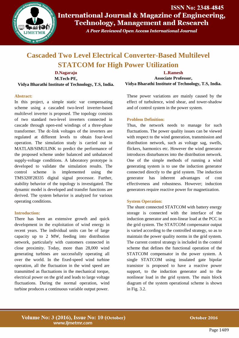
Load Compensation:
In this case, the STATCOM compensates the reactive
power of the load. Initially, STATCOM is supplying
a current of 0.5 p.u. At t= 2.0 s, the load current is
increased so that STATCOM supplies its rated
current of 1 p.u. Fig. 8(a) shows source voltage and
converter current, while Fig. 8(b) shows the dc-link
voltages of two inverters. The dc-link voltages are
maintained at their respective reference values when
the operating conditions are changed.
Fig 8: Load compensation. (a) Source voltage and
inverter current.
(b) DC-link voltages of two inverters
Operation during the Fault Condition
In this case, a single-phase-to-ground fault is created
at t=1.2 s, on the phase of the HV side of the 33/11-
kVtransformer.The fault is cleared after 200 ms. Fig.
9(a) shows voltages across the LV side of the 33/11-
kV transformer. Fig. 9(b) and (c) shows the - axes
components of negative-sequence current of the
converter. These currents are regulated at zero during
the fault condition.
Fig 9: Operation during fault. (a) Grid voltages on
the LV side of the transformer.(b) -axis negative-
sequence current component. (c) -axis negative-
sequence current component.

Page 1492
SIMULATION RESULTS
STATCOM Reactive
Fig 10:statcom reactive
OUT PUTS
Fig.11:Source output at reactive condition
Fig12:statcom output at reactive condition
Fig 13:vdc2 output at reactive condition
Fig14: vdc3 output at reactive condition
STATCOM fault
Fig 15:statcom fault
OUTPUTS:
Fig 16: source output at fault condition
Fig 17:stat com output at faultcondition
Fig 18:vdc2 output at fault condition
Fig19: vdc3 at fault condition
5.3STATCOM load com
Fig 20: stat com load com
Page 1493
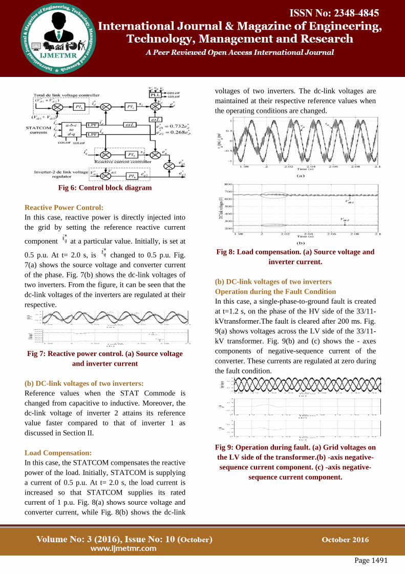
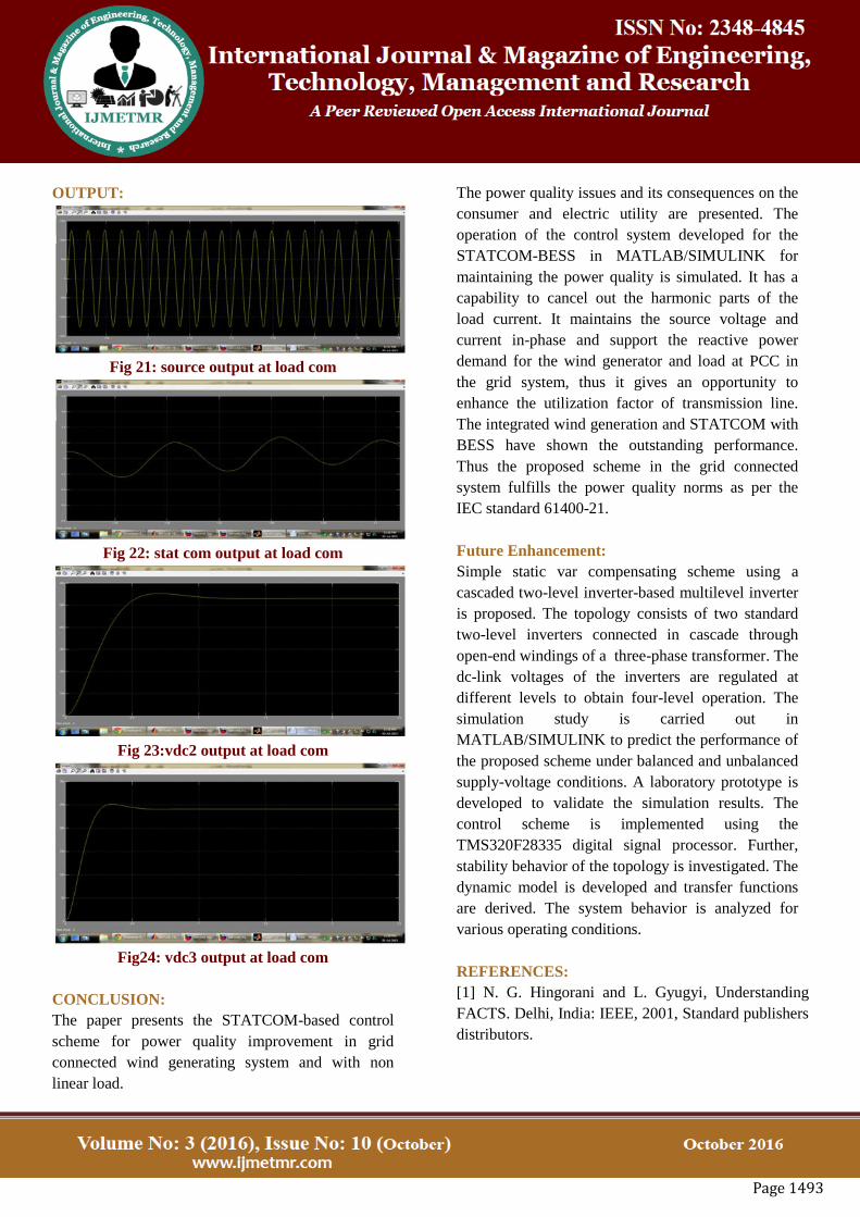
OUTPUT:
Fig 21: source output at load com
Fig 22: stat com output at load com
Fig 23:vdc2 output at load com
Fig24: vdc3 output at load com
CONCLUSION:
The paper presents the STATCOM-based control
scheme for power quality improvement in grid
connected wind generating system and with non
linear load.
The power quality issues and its consequences on the
consumer and electric utility are presented. The
operation of the control system developed for the
STATCOM-BESS in MATLAB/SIMULINK for
maintaining the power quality is simulated. It has a
capability to cancel out the harmonic parts of the
load current. It maintains the source voltage and
current in-phase and support the reactive power
demand for the wind generator and load at PCC in
the grid system, thus it gives an opportunity to
enhance the utilization factor of transmission line.
The integrated wind generation and STATCOM with
BESS have shown the outstanding performance.
Thus the proposed scheme in the grid connected
system fulfills the power quality norms as per the
IEC standard 61400-21.
Future Enhancement:
Simple static var compensating scheme using a
cascaded two-level inverter-based multilevel inverter
is proposed. The topology consists of two standard
two-level inverters connected in cascade through
open-end windings of a three-phase transformer. The
dc-link voltages of the inverters are regulated at
different levels to obtain four-level operation. The
simulation study is carried out in
MATLAB/SIMULINK to predict the performance of
the proposed scheme under balanced and unbalanced
supply-voltage conditions. A laboratory prototype is
developed to validate the simulation results. The
control scheme is implemented using the
TMS320F28335 digital signal processor. Further,
stability behavior of the topology is investigated. The
dynamic model is developed and transfer functions
are derived. The system behavior is analyzed for
various operating conditions.
REFERENCES:
[1] N. G. Hingorani and L. Gyugyi, Understanding
FACTS. Delhi, India: IEEE, 2001, Standard publishers
distributors.

Page 1494
[2] B. Singh, R. Saha, A. Chandra, and K. Al-Haddad,
“Static synchronous compensators (STATCOM): A
review,” IET Power Electron., vol. 2, no. 4, pp. 297–
324, 2009.
[3] H. Akagi, H. Fujita, S. Yonetani, and Y. Kondo,
“A 6.6-kV transformer less STATCOM based on a
five-level diode-clamped PWM converter: System
design and experimentation of a 200-V 10-kVA
laboratory model,” IEEE Trans. Ind. Appl., vol. 44, no.
2, pp. 672–680,
Mar./Apr. 2008.
[4] A. Shukla, A. Ghosh, and A. Joshi, “Hysteresis
current control operation of flying capacitor multilevel
inverter and its application in shunt compensation of
distribution systems,” IEEE Trans. Power Del., vol.
22, no. 1, pp. 396–405, Jan. 2007.
[5] H. Akagi, S. Inoue, and T. Yoshii, “Control and
performance of a transformerless cascaded PWM
STATCOM with star configuration,” IEEETrans. Ind.
Appl., vol. 43, no. 4, pp. 1041–1049, Jul./Aug. 2007.
[6] Y. Liu, A. Q. Huang, W. Song, S. Bhattacharya,
and G. Tan, “Smallsignal model-based control strategy
for balancing individual dc capacitor voltages in
cascade multilevel inverter-based STATCOM,” IEEE
Trans. Ind. Electron., vol. 56, no. 6, pp. 2259–2269,
Jun. 2009.
[7] H. P.Mohammadi and M.T.Bina, “A transformer
less medium-voltage STATCOM topology based on
extended modular multilevel converters,” IEEE Trans.
Power Electron., vol. 26, no. 5, pp. 1534–1545, May
2011.
[8] X. Kou, K. A. Corzine, and M. W. Wielebski,
“Overdistention operation of cascaded multilevel
inverters,” IEEE Trans. Ind. Appl., vol. 42, no. 3, pp.
817–824, May/Jun. 2006.
[9] K. K. Mohaptra, K. Gopakumar, and V. T.
Somasekhar, “A harmonic elimination and suppression
scheme for an open-end winding induction motor
drive,” IEEE Trans. Ind. Electron., vol. 50, no. 6, pp.
1187–1198, Dec. 2003.
[10] Y. Kawabata, N. Yahata,M. Horii, E. Egiogu, and
T. Kawabata, “SVG using open winding transformer
and two inverters,” in Proc., 35th AnnualIEEE Power
Electron. Specialists Conf., 2004, pp. 3039–3044.
[11] S. Ponnaluri, J. K. Steinke, P. Steimer, S.
Reichert, and B. Buchmann, “Design comparison and
control of medum voltage STATCOM with novel twin
converter topology,” in Proc., 35th Annu. IEEE Power
Electron.Specialists Conf., 2004, pp. 2546–2550.
[12] N. N. V. Surendra Babu, D. Apparao, and B. G.
Fernandes, “Asymmetrical dc link voltage balance of a
cascaded two level inverter based STATCOM,” in
Proc., IEEE TENCON, 2010, pp. 483–488.
[13] IEEE Criteria for Class IE Electric Systems, IEEE
Standard 141-1993.
[14] C. Schauder and H. Mehta, “Vector analysis and
control of advanced static VAr compensators,” in Proc.
Inst. Elect. Eng. C., Jul. 1993, vol. 140, no. 4, pp. 299–
305.
[15] D. G. Holmes and T. A. Lipo, “IEEE series on
power engineering,” in Pulse Width Modulation for
Power Converters: Principles and Practice. Piscataway,
NJ, USA: IEEE, 2003.
[16] B. Blazic and I. Papic, “Improved D-statcom
control for operation with unbalanced currents and
voltages,” IEEE Trans. Power Del., vol. 21, no. 1, pp.
225–233, Jan. 2006.