case and associated parts (1 of 2) - atra part id.pdf · case and associated parts (1 of 2) ... 36...
TRANSCRIPT

102
23
4
56
71
72
29
28
27
26
2524
2322
2120
103
12
11
13
14
15
16
105
17
18
19
SOMEMODELS
9
10
7
SOME MODELS
9695
SOME MODELS
SOME MODELS
102 103 100 106
73
75
76
101
3433
323137
30
99
34
36
35
75
73
74
76
10794
102
1
98
97
YH586909-4L60-E
Case and Associated Parts (1 of 2)
Figure 98

103
1 TORQUE CONVERTER ASSEMBLY(MODEL DEPENDENT)
2 PUMP TO CASE BOLT
3 PUMP TO CASE BOLT O-RING
4 OIL PUMP ASSEMBLY
5 OIL SEAL (PUMP TO CASE)
6 PUMP COVER TO CASE GASKET
7 CASE BUSHING
9 TRANSMISSION VENT ASSEMBLY
10 OIL COOLER PIPE CONNECTOR (MODEL DEPENDENT)
11 CASE SERVO PLUG
12 SERVO RETURN SPRING
13 2ND APPLY PISTON PIN
14 RETAINER RING (2ND APPLY PISTON)
15 SERVO CUSHION SPRING RETAINER
16 SERVO CUSHION SPRING (OUTER)
17 2ND APPLY PISTON
18 OIL SEAL RING (2ND APPLY PISTON - OUTER)
19 OIL SEAL RING (2ND APPLY PISTON - INNER)
20 SERVO PISTON HOUSING (INNER)
21 O-RING SEAL
22 SERVO APPLY PIN SPRING
23 SERVO APPLY PIN WASHER
24 RETAINER RING (APPLY PIN)
25 4TH APPLY PISTON
26 OIL SEAL RING (4TH APPLY PISTON - OUTER)
27 O-RING SEAL (2-4 SERVO COVER)
28 2-4 SERVO COVER
29 SERVO COVER RETAINING RING
30 CASE EXTENSION TO CASE SEAL
31 CASE EXTENSION (MODEL DEPENDENT)
32 CASE EXTENSION TO CASE BOLT
33 CASE EXTENSION BUSHING
34 CASE EXTENSION OIL SEAL ASSEMBLY(MODEL DEPENDENT)
35 SPEED SENSOR RETAINING BOLT
36 INTERNAL TRANSMISSION SPEED SENSOR
37 O-RING SEAL (ITSS TO CASE EXTENSION)
71 FILTER SEAL
72 TRANSMISSION OIL FILTER ASSEMBLY(MODEL DEPENDENT)
73 TRANSMISSION OIL PAN GASKET
74 CHIP COLLECTOR MAGNET
75 TRANSMISSION OIL PAN (MODEL DEPENDENT)
76 TRANSMISSION OIL PAN SCREW
94 CONVERTER HOUSING TO CASE BOLT
95 OIL COOLER QUICK CONNECTOR(MODEL DEPENDENT)
96 OIL COOLER QUICK CONNECT CLIP(MODEL DEPENDENT)
97 CONVERTER HOUSING ACCESS HOLE PLUG(MODEL DEPENDENT)
98 CONVERTER BOLT INSPECTION PLATE(MODEL DEPENDENT)
99 CUP D4 ORIFICE PLUG
100 A/TRANS. CASE STUD (Y-CAR ONLY)
101 A/TRANS. OIL PAN PLUG ASSEMBLY (Y-CAR ONLY)
102 CONVERTER HOUSING (MODEL DEPENDENT)
103 MAIN CASE SECTION (MODEL DEPENDENT)
105 SERVO CUSHION SPRING (INNER)(MODEL DEPENDENT)
106 CASE OIL SEAL ASSEMBLY (Y-CAR ONLY)
107 PLUG ASSEMBLY A/TRANS. OIL PAN HEX HEAD(C/K TRUCK ONLY)
Case and Associated Parts (1 of 2) Legend

104
66
65
67
68
38
394241
40
103
L
D3
R
D2
434445
46
47
49
48
54
104
52
50
55
56
57
63
64
61
60
62
59
58
53
7769
70
91
93
38 TRANSMISSION CASE PLUG (ACCUMULATOR BLEED)39 PRESSURE PLUG40 3RD ACCUMULATOR RETAINER AND BALL
ASSEMBLY (#7)41 BAND ANCHOR PIN42 RETAINER AND BALL ASSEMBLY (DOUBLE ORIFICE)
(#10)43 ACCUMULATOR PISTON PIN44 3-4 ACCUMULATOR PISTON45 OIL SEAL RING (3-4 ACCUMULATOR PISTON)46 3-4 ACCUMULATOR SPRING (MODEL DEPENDENT)47 SPACER PLATE TO CASE GASKET48 VALVE BODY SPACER PLATE49 SHIFT SOLENOIDS SCREEN50 PRESSURE CONTROL SOLENOID SCREEN52 SPACER PLATE TO VALVE BODY GASKET53 SPACER PLATE SUPPORT PLATE54 1-2 ACCUMULATOR SPRING (OUTER)55 OIL SEAL RING (1-2 ACCUMULATOR)56 1-2 ACCUMULATOR PISTON57 1-2 ACCUMULATOR COVER AND PIN ASSEMBLY
58 ACCUMULATOR COVER BOLT59 ACCUMULATOR COVER BOLT60 CONTROL VALVE BODY ASSEMBLY61 CHECKBALL (#2, 3, 4, 5, 6, 8, 12)62 VALVE BODY BOLT63 MANUAL DETENT SPRING ASSEMBLY64 MANUAL DETENT SPRING BOLT65 WIRING HARNESS PASS-THRU CONNECTOR O-RING
SEAL66 WIRING HARNESS SOLENOID ASSEMBLY67 O-RING SEAL (SOLENOID)68 HEX WASHER HEAD BOLT (SOLENOID)69 TRANSMISSON FLUID PRESSURE MANUAL VALVE
POSITION SWITCH ASSEMBLY70 PRESSURE SWITCH ASSEMBLY BOLT77 SPACER PLATE SUPPORT BOLT91 NUMBER 1 CHECKBALL93 DIPSTICK STOP BRACKET (MODEL DEPENDENT)
103 MAIN CASE SECTION (MODEL DEPENDENT)104 1-2 ACCUMULATOR SPRING (INNER)
YH283778-4L60-E
Case and Associated Parts (2 of 2)
Figure 99

105
200 PUMP BODY
201 OIL SEAL RING (SLIDE TO WEAR PLATE)
202 O-RING SEAL (SLIDE SEAL BACK-UP)
203 PUMP SLIDE
204 PIVOT PIN SPRING
205 PIVOT SLIDE PIN
206 PUMP SLIDE SPRING (OUTER)
207 PUMP SLIDE SPRING (INNER)
208 PUMP SLIDE SEAL SUPPORT
209 PUMP SLIDE SEAL
210 PUMP VANE RING
211 ROTOR GUIDE
212 OIL PUMP ROTOR
213 PUMP VANE
214 STATOR SHAFT
215 PUMP COVER
216 PRESSURE REGULATOR VALVE
217 PRESSURE REGULATOR VALVE SPRING
218 PRESSURE REGULATOR ISOLATOR SPRING
219 REVERSE BOOST VALVE
220 REVERSE BOOST VALVE SLEEVE
221 OIL PUMP REVERSE BOOST VALVE RETAINING RING
222 OIL PUMP CONVERTER CLUTCH VALVE RETAININGRING
223 STOP VALVE
224 CONVERTER CLUTCH VALVE
225 CONVERTER CLUTCH VALVE SPRING (INNER)
226 CONVERTER CLUTCH VALVE SPRING (OUTER)
227 PRESSURE RELIEF BOLT RIVET
228 PRESSURE RELIEF BALL
229 PRESSURE RELIEF SPRING
230 OIL SEAL RING (STATOR SHAFT)
231 OIL PUMP COVER SCREEN SEAL
232 OIL PUMP COVER SCREEN
233 COVER TO BODY BOLT
234 STATOR SHAFT BUSHING (FRONT)
235 OIL PUMP COVER PLUG (FWD CLUTCH FEED)
236 OIL PUMP COVER PLUG
237 CHECK VALVE RETAINER AND BALL ASSEMBLY
238 CONVERTER CLUTCH SIGNAL ORIFICE (CUP PLUG)
240 CUP ORIFICE PLUG
241 STATOR SHAFT BUSHING (REAR)
242 PUMP BODY BUSHING
243 OIL SEAL ASSEMBLY
244 FRONT HELIX RETAINER
215
236240
232231
228
229
227241
230233
236
236
238237
236
236
236
237
235234
210
212
213
211
210
203
208
209
202
201
200
242
243
244
226
225
224
223
222
216
217
218
219
220
221
205204
206
207
214
XH405105-4L60-E
Oil Pump Assembly
Figure 100

106
350
353
354
355356 357
358360
359361
362363
364
367A
366
365
368
369
367B
395
395
360
372
371
370
374
375
376
395
378364
377
366 1-2 SHIFT VALVE
367A 1-2 SHIFT SOLENOID VALVE
367B 2-3 SHIFT SOLENOID VALVE
368 2-3 SHIFT VALVE
369 2-3 SHUTTLE VALVE
370 1-2 ACCUMULATOR VALVE SPRING
371 1-2 ACCUMULATOR VALVE
372 1-2 ACCUMULATOR VALVE SLEEVE
374 ACTUATOR FEED LIMIT VALVE
375 ACTUATOR FEED LIMIT VALVE SPRING
376 BORE PLUG
377 PRESSURE CONTROL SOLENOID VALVE
378 PRESSURE CONTROL SOLENOID RETAINER
395 BORE PLUG AND SOLENOID RETAINER
350 CONTROL VALVE BODY
353 FORWARD ACCUMULATOR OIL SEAL
354 FORWARD ACCUMULATOR PISTON
355 FORWARD ACCUMULATOR PIN
356 FORWARD ACCUMULATOR SPRING
357 FORWARD ABUSE VALVE
358 FORWARD ABUSE VALVE SPRING
359 BORE PLUG
360 COILED SPRING PIN
361 LOW OVERRUN VALVE
362 LOW OVERRUN VALVE SPRING
363 FORWARD ACCUMULATOR COVER
364 FORWARD ACCUMULATOR COVER BOLT
365 1-2 SHIFT VALVE SPRING
XH405111-4L60-E
Control Valve Body Assembly (1 of 2)
Figure 101

107
380
381 382
383
395
384
381
395
381
395
385386
381
395387
388360
359390
389 391
392
394
395
340
350
395
396
397
SOMEMODELS
398
380
381
395
397398
340 MANUAL VALVE
350 CONTROL VALVE BODY
359 BORE PLUG
360 COILED SPRING PIN
380 REGULATOR APPLY VALVE (MODEL DEPENDENT)
381 BORE PLUG
382 4-3 SEQUENCE VALVE SPRING
383 4-3 SEQUENCE VALVE
384 3-4 RELAY VALVE
385 3-4 SHIFT VALVE
386 3-4 SHIFT VALVE SPRING
387 REVERSE ABUSE VALVE
388 REVERSE ABUSE VALVE SPRING
389 3-2 DOWNSHIFT VALVE
390 3-2 DOWNSHIFT VALVE SPRING
391 3-2 CONTROL VALVE
392 3-2 CONTROL VALVE SPRING
394 3-2 CONTROL SOLENOID VALVE
395 BORE PLUG AND SOLENOID RETAINER
396 TCC PWM SOLENOID VALVE
397 REGULATOR APPLY SPRING (MODEL DEPENDENT)
398 ISOLATOR VALVE (MODEL DEPENDENT)
XH405114-4L60-E
Control Valve Body Assembly (2 of 2)
Figure 102

108
602 601 603 605 606 608B 608A 607 609 610 611 612A 612B 613 614 615 616
645A 645B 636 638 639 642637 643
643 644 646 648 649A 649B
653651650 654A 654B 655 656
619688
620
632 634 635633630628627626625623622600621698
618617
653 654A 654B 655652
640657 659
SOME MODELS
YH213098-4L60-E
Internal Components (1 of 2)
Figure 103

109
600 3-4 CLUTCH BOOST SPRING ASSEMBLY (5)
601 THRUST WASHER (PUMP TO DRUM)
602 2-4 BAND ASSEMBLY
603 REVERSE INPUT CLUTCH BUSHING (FRONT)
605 REVERSE INPUT CLUTCH HOUSING AND DRUMASSEMBLY
606 REVERSE INPUT CLUTCH BUSHING (REAR)
607 REVERSE INPUT CLUTCH PISTON ASSEMBLY
608A REVERSE INPUT CLUTCH SEAL (INNER)
608B REVERSE INPUT CLUTCH SEAL (OUTER)
609 REVERSE INPUT CLUTCH SPRING ASSEMBLY
610 REVERSE INPUT CLUTCH SPRING RETAINER RING
611 REVERSE INPUT CLUTCH PLATE (BELLEVILLE)
612A REVERSE INPUT CLUTCH TURBULATOR PLATE(STEEL)
612B REVERSE INPUT CLUTCH PLATE ASSEMBLY (FIBER)
613 REVERSE INPUT CLUTCH BACKING PLATE(SELECTIVE)
614 REVERSE INPUT CLUTCH RETAINING RING
615 STATOR SHAFT/ SELECTIVE WASHER BEARINGASSEMBLY
616 THRUST WASHER (SELECTIVE)
617 CHECK VALVE RETAINER AND BALL ASSEMBLY
618 O-RING SEAL (TURBINE SHAFT/ SELECTIVE WASHER)(MODEL DEPENDENT)
619 OIL SEAL RING (SOLID)
620 RETAINER AND CHECKBALL ASSEMBLY
621 INPUT HOUSING AND SHAFT ASSEMBLY(MODEL DEPENDENT)
622 O-RING SEAL INPUT TO FORWARD CLUTCH HOUSING
623 3RD AND 4TH CLUTCH PISTON
625 3RD AND 4TH CLUTCH RING (APPLY)
626 3RD AND 4TH CLUTCH SPRING ASSEMBLY
627 FORWARD CLUTCH HOUSING RETAINER AND BALLASSEMBLY
628 FORWARD CLUTCH HOUSING
630 FORWARD CLUTCH PISTON
632 OVERRUN CLUTCH PISTON
633 OVERRUN CLUTCH BALL
634 OVERRUN CLUTCH SPRING ASSEMBLY
635 OVERRUN CLUTCH SPRING RETAINER SNAP RING
636 INPUT HOUSING TO OUTPUT SHAFT SEAL
637 INPUT SUN GEAR BEARING ASSEMBLY
638 OVERRUN CLUTCH HUB RETAINING SNAP RING
639 OVERRUN CLUTCH HUB
640 FORWARD SPRAG CLUTCH INNER RACE AND INPUTSUN GEAR ASSEMBLY
642 FORWARD SPRAG ASSEMBLY
643 SPRAG ASSEMBLY RETAINER RING
644 FORWARD CLUTCH RACE (OUTER)
645A OVERRUN CLUTCH PLATE (STEEL)
645B OVERRUN CLUTCH PLATE ASSEMBLY (FIBER)
646 FORWARD CLUTCH PLATE (APPLY)
648 FORWARD CLUTCH PLATE (WAVED)
649A FORWARD CLUTCH PLATE (STEEL)
649B FORWARD CLUTCH PLATE ASSEMBLY (FIBER)
650 FORWARD CLUTCH BACKING PLATE (SELECTIVE)
651 FORWARD CLUTCH BACKING PLATE RETAINER RING
652 3RD AND 4TH CLUTCH PLATE (STEEL)(2.2L ENGINE ONLY)
653 3RD AND 4TH CLUTCH APPLY PLATE (STEPPED)
654A 3RD AND 4TH CLUTCH PLATE ASSEMBLY (FIBER)(QUANTITY MODEL DEPENDENT)
654B 3RD AND 4TH CLUTCH PLATE (STEEL)(QUANTITY MODEL DEPENDENT)
655 3RD AND 4TH CLUTCH BACKING PLATE (SELECTIVE)(MODEL DEPENDENT)
656 3RD AND 4TH CLUTCH BACKING PLATE RETAINERRING
657 INPUT SUN GEAR FRONT BUSHING
659 INPUT SUN GEAR REAR BUSHING
688 CUP PLUG
698 ORIFICED CUP PLUG
Internal Components (1 of 2) Legend

110
661 662 663 664 665 666 667
668 669 670 671 672 673 674 675 676 677 678 679 677 681 697
690 691 692 693 694 695 696A 696B 696C
SOMEMODELS
SOMEMODELS
682C 682B 682A 683 684682D 685 686 687 699
681A 681E 681D
681C681C
681D
681B
680
662B662F
662E
662D662D662A662C662C
YH213103-4L60-E
Internal Components (2 of 2)
Figure 104
661 OUTPUT SHAFT TO INPUT CARRIER RETAINER662 INPUT CARRIER ASSEMBLY
662A INPUT CARRIER PINION GEAR PIN662B INPUT CARRIER PINION GEAR662C INPUT CARRIER PINION WASHER662D INPUT CARRIER PINION WASHER662E INPUT CARRIER SPACER662F INPUT CARRIER PINION/GEAR BEARING ROLLER663 THRUST BEARING ASSEMBLY (INPUT CARRIER TO
REACTION SHAFT)664 INPUT INTERNAL GEAR665 REACTION CARRIER SHAFT FRONT BUSHING666 REACTION CARRIER SHAFT667 REACTION CARRIER SHAFT REAR BUSHING668 REACTION SHAFT/INTERNAL GEAR RETAINER RING669 THRUST WASHER (REACTION SHAFT SHELL)670 REACTION SUN SHELL671 REACTION SUN GEAR RETAINER RING672 REACTION SUN BUSHING673 REACTION SUN GEAR674 THRUST WASHER (RACE/REACTION SHELL)675 LOW AND REVERSE ROLLER CLUTCH RACE676 LOW AND REVERSE SUPPORT TO CASE RETAINER
RING677 LOW AND REVERSE ROLLER ASSEMBLY RETAINER
RING (CAM)
678 LOW AND REVERSE ROLLER CLUTCH ASSEMBLY679 LOW AND REVERSE CLUTCH SUPPORT ASSEMBLY680 LOW AND REVERSE CLUTCH SUPPORT RETAINER
SPRING681 REACTION CARRIER ASSEMBLY
681A REACTION CARRIER PINION GEAR PIN681B REACTION CARRIER PINION GEAR681C REACTION CARRIER PINION BAT WINGED WASHER681D REACTION CARRIER PINION WASHER681E REACTION CARRIER PINION/GEAR NEEDLE ROLLER682A LOW AND REVERSE CLUTCH PLATE (WAVED)682B SPACER LOW AND REVERSE CLUTCH PLATE
(SELECTIVE)682C LOW AND REVERSE CLUTCH PLATE ASSEMBLY
(FIBER)682D LOW AND REVERSE CLUTCH TURBULATOR PLATE
(STEEL)683 THRUST BEARING ASSEMBLY (REACTION CARRIER/
SUPPORT)684 INTERNAL REACTION GEAR685 INTERNAL REACTION GEAR SUPPORT686 REACTION GEAR/SUPPORT RETAINER RING687 OUTPUT SHAFT690 OUTPUT SHAFT SLEEVE (MODEL DEPENDENT)691 OUTPUT SHAFT SEAL (MODEL DEPENDENT)692 REACTION GEAR SUPPORT TO CASE BEARING693 LOW AND REVERSE CLUTCH RETAINER RING694 LOW AND REVERSE CLUTCH SPRING ASSEMBLY695 LOW AND REVERSE CLUTCH PISTON
696A LOW AND REVERSE CLUTCH SEAL (OUTER)696B LOW AND REVERSE CLUTCH SEAL (CENTER)696C LOW AND REVERSE CLUTCH SEAL (INNER)
697 OIL DEFLECTOR (HIGH OUTPUT MODELS ONLY)699 INTERNAL TRANSMISSION SPEED SENSOR ROTOR

111
87 86 85 9088
89
83
8284
8180
79
78
78 STEEL CUP PLUG
79 PARKING BRAKE PAWL SHAFT
80 PARKING PAWL RETURN SPRING
81 PARKING BRAKE PAWL
82 MANUAL SHAFT SEAL
83 MANUAL SHAFT RETAINER
84 MANUAL SHAFT (MODEL DEPENDENT)
85 PARKING LOCK ACTUATOR ASSEMBLY
86 PARKING LOCK BRACKET
87 PARKING LOCK BRACKET BOLT (2)
88 INSIDE DETENT LEVER
89 MANUAL VALVE LINK
90 HEX HEAD NUT
WH65111-4L60-E
Parking Pawl and Actuator Assembly
Figure 105

112
BASIC SPECIFICATIONS
Vehicles used in:
DIVISION MODEL
C/K Truck Chevrolet/GMC Pickup/Suburban
F Chevrolet/Pontiac Camaro/Firebird
G Van Chevrolet/GMC Express/Savana
M/L Van Chevrolet/GMC Astro/Safari
S/T Truck Chevrolet/GMC S10/Sonoma
Y Chevrolet Corvette
Transmission DriveRear Wheel Drive4-Wheel DriveAll Wheel Drive
Transmission Type4L60-E = 4: Four Speed
L: Longitudinal Mount60: Product Series E: Electronically Controlled
Automatic Overdrive with a Torque Converter Clutch Assembly.
Current Engine Range2.5 L to 5.7 L Gasoline
6.2 L Diesel
Control SystemsShift Pattern – (2) Two-way on/off solenoidsShift Quality – Pressure Control Solenoid
3-2 Control SolenoidTorque Converter Clutch – Pulse Width Modulated
solenoid control
Gear Ratios1st 3.0592nd 1.6253rd 1.0004th 0.696Rev 2.294
Maximum Engine Torque475 N•m (350 lb ft)
Maximum Gearbox Torque910 N•m (670 lb ft)
Maximum Shift Speed1-2 6,000 RPM2-3 6,000 RPM3-4 6,000 RPM
Maximum Gross Vehicle Weight3,900 kg (8,600 lb)
Transmission Fluid TypeDexron® III
Transmission Fluid Capacities (Approximate)245 mm Converter (Dry): 7.9 L (8.4 qt)258 mm Converter (Dry): 8.8 L (9.3 qt)298 mm Converter (Dry): 10.6 L (11.2 qt)300 mm Converter (Dry): 10.6 L (11.2 qt)
Transmission Weight245 mm Converter (Dry): 65.4 kg (144.30 lb)
(Wet): 72.4 kg (159.55 lb)
258 mm Converter (Dry): 79.9 kg (176.60 lb)(Wet): 89.2 kg (197.70 lb)
298 mm Converter (Dry): 70.5 kg (155.70 lb)(Wet): 80.5 kg (176.16 lb)
300 mm Converter (Dry): 70.5 kg (155.70 lb)(Wet): 80.5 kg (176.16 lb)
Converter Sizes Available245, 258, 298 and 300 mm Converter (Reference)
Converter Bolt Circle DiametersFor 245 and 258 mm Converter – 247.65 mm (Reference)For 298 mm Converter – 273.05 mm (Reference)For 300 mm Converter – 275.05 mm (Reference)
Converter Stall Torque Ratio RangeFor 245 mm Converter – 1.63 to 2.70For 258 mm Converter – 1.65 to 2.07For 298 mm Converter – 1.84 to 2.34For 300 mm Converter – 1.84 to 2.34
Converter “K” Factor RangeFor 245 mm Converter – 122 to 240For 258 mm Converter – 110 to 179For 298 mm Converter – 100 to 140For 300 mm Converter – 100 to 140
Not all “K” Factors are applicable across the range of Converter Stall Torque Ratios.
Transmission Packaging Information*Engine Mounting Face to Rear of Case
593.50 mm (Reference - Less Extension)Overall Length
Current Minimum: 756.20 mm (Reference)Current Maximum: 778.30 mm (Reference)
Case Extension LengthsDetermined by Customer RequirementsCurrent Minimum: 162.70 mm (Reference)Current Maximum: 184.80 mm (Reference)
Current Converter Housings Available245 mm and 258 mm (Small Bell Style)298 mm and 300 mm (Large Bell Style)
Two-Piece Case with Separate ExtensionConverter HousingMain Case
*All dimensions shown are nominal.
Seven Position Quadrant(P, R, N, D , D, 2, 1) / (P, R, N, D , 3, 2, 1)
Pressure Taps AvailableLine Pressure
Information may vary with application. All information, illustrations and specificationscontained in this book are based on the latest product information available at the time ofpublication. The right is reserved to make changes at any time without notice.
HYDRA-MATIC 4L60-E TRANSMISSION
RPO M30
HYDRA-MATIC 4L60-E(FOUR-SPEED)
Produced at: Romulus, MichiganToledo, OhioU.S.A.Mexico
29
HYDRAULIC CONTROL COMPONENTS
Figure 29
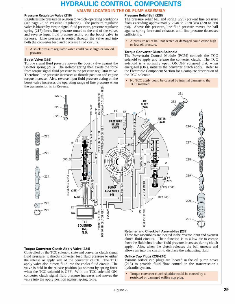
Pressure Relief Ball (228)
The pressure relief ball and spring (229) prevent line pressurefrom exceeding approximately 2240 to 2520 kPa (320 to 360psi). Above this pressure, line fluid pressure moves the ballagainst spring force and exhausts until line pressure decreasessufficiently.
Torque Converter Clutch SolenoidThe Powertrain Control Module (PCM) controls the TCCsolenoid to apply and release the converter clutch. The TCCsolenoid is a normally open, ON/OFF solenoid that, whenenergized (ON), initiates the converter clutch apply. Refer tothe Electronic Component Section for a complete description ofthe TCC solenoid.
226
225
224
223
222
216
217
218
219
220
221
232
231
228
229
227
BOOS
T VA
LVE
PRES
S RE
G
REV INPUT
DECR
EASE
LINE
LINE
EX
FILTER(232)
AIRBLEED(240)
1SU
CTIO
N
SUCT
ION
LINE
EX
PRESSURERELIEFVALVE
PUMPASSEMBLY
(4)
4
TCCSOLENOID
(66)N.O.
TORQUE SIG
FORW
ARD
CLUT
CH F
EED
FORW
ARD
CLUT
CH F
EED
FORW
ARD
CLUT
CH F
EED
2
➤
➤
➤
➤➤
➤
EX
CONV
FD
EX
EX
EX
➤
➤
➤
OVER
RUN
CLUT
CHOV
ERRU
N CL
UTCH
OVER
RUN
CLUT
CH
EX(237)
REVE
RSE
INPU
TRE
VERS
E IN
PUT
EX
➤➤
CONV
ERTE
R CL
UTCH
VAL
VE
COOLER
RELE
ASE
RELE
ASE
APPL
YAP
PLY
EX
➤
➤
EX
➤
➤
CONV
FD
➤
➤
➤
➤
➤
➤
➤
REGU
LATE
D AP
PLY
(237)➤
(238)
➤
➤
➤
➤
➤
➤
➤
➤
➤
VALVES LOCATED IN THE OIL PUMP ASSEMBLY
Pressure Regulator Valve (216)
Regulates line pressure in relation to vehicle operating conditions(see page 28 on Pressure Regulation). The pressure regulatorvalve is biased by torque signal fluid pressure, pressure regulatorspring (217) force, line pressure routed to the end of the valve,and reverse input fluid pressure acting on the boost valve inReverse. Line pressure is routed through the valve and intoboth the converter feed and decrease fluid circuits.
Boost Valve (219)Torque signal fluid pressure moves the boost valve against theisolator spring (218). The isolator spring then exerts the forcefrom torque signal fluid pressure to the pressure regulator valve.Therefore, line pressure increases as throttle position and enginetorque increase. Also, reverse input fluid pressure acting on theboost valve increases the operating range of line pressure whenthe transmission is in Reverse.
• A stuck pressure regulator valve could cause high or low oilpressure.
• No TCC apply could be caused by internal damage to theTCC solenoid.
• A pressure relief ball not seated or damaged could cause highor low oil pressure.
Torque Converter Clutch Apply Valve (224)Controlled by the TCC solenoid state and converter clutch signalfluid pressure, it directs converter feed fluid pressure to eitherthe release or apply side of the converter clutch. The TCCapply valve also directs fluid into the cooler fluid circuit. Thevalve is held in the release position (as shown) by spring forcewhen the TCC solenoid is OFF. With the TCC solenoid ON,converter clutch signal fluid pressure increases and moves thevalve into the apply position against spring force.
Retainer and Checkball Assemblies (237)These two assemblies are located in the reverse input and overrunclutch fluid circuits. Their function is to allow air to escapefrom the fluid circuit when fluid pressure increases during clutchapply. Also, when the clutch releases the ball unseats andallows air into the circuit to displace the exhausting fluid.
Orifice Cup Plugs (238-240)Various orifice cup plugs are located in the oil pump cover(215) to provide fluid flow control in the transmission’shydraulic system.
• Torque converter clutch shudder could be caused by arestricted or damaged orifice cup plug.

30
HYDRAULIC CONTROL COMPONENTSVALVES LOCATED IN THE CONTROL VALVE BODY
3-4 Shift Valve (385)Biased by 1-2 signal fluid pressure from the 1-2 shift solenoid,spring force and D3 fluid pressure, the 3-4 shift valve controlsthe routing of 3-4 signal fluid. To obtain Fourth gear, 1-2 signalfluid pressure moves the valve against spring force and directs3-4 signal fluid into the 4th signal fluid circuit. However, inManual Third, D3 fluid assists spring force and holds the valveagainst 1-2 signal fluid pressure to prevent Fourth gear underany conditions. In the downshifted position, the 4th signal fluidcircuit is open to an exhaust past the valve.
3-2 Downshift Valve (389)The 3-2 downshift valve helps control the 2-4 band apply rateduring a 3-2 downshift. During the downshift, 3-4 clutch fluidpressure holds the valve against spring force before exhausting.This allows 2nd fluid to quickly fill the 2nd clutch fluid circuitfor a faster 2-4 band apply.
Reverse Abuse Valve (387)The reverse abuse valve provides a faster apply of the reverseinput clutch when throttle position is greater than idle. Duringthese conditions, reverse fluid pressure increases and moves thevalve against spring force. Reverse fluid can then quickly fillthe reverse input fluid circuit. This bypasses the control of thereverse input orifice (#17) for a faster clutch apply.
3-2 Control Solenoid Valve (394)
The 3-2 control solenoid valve is a normally closed ON/OFFsolenoid controlled by the PCM. The solenoid is used to routeactuator feed limit (AFL) fluid into the 3-2 signal fluid circuit tocontrol the position of the 3-2 control valve. The PCM controlsthe solenoid state during a 3-2 downshift according to vehiclespeed.
3-2 Control Valve (391)The 3-2 control valve regulates the exhaust of 3rd accumulatorfluid into the 3-4 clutch fluid circuit during a 3-2 downshift. Thisregulation is controlled by 3-2 signal fluid pressure from the 3-2control solenoid valve. At high vehicle speed, 3-2 signal fluidpressure moves the valve against spring force to block exhausting3rd accumulator fluid from entering the 3-4 clutch fluid circuit. Atlow vehicle speed, 3-2 signal fluid pressure is OFF and the valve isheld in the open position by spring force to allow exhausting 3rdaccumulator fluid to enter the 3-4 clutch fluid circuit.
Manual Valve (340)
The manual valve is supplied with line pressure from the pressureregulator valve and is mechanically linked to the gear selectorlever. When a gear range is selected, the manual valve directsline pressure into various circuits by opening and closing fluidpassages. The fluid circuits fed by the manual valve includeReverse, PR, D4, D3, D2 and lo.
Pressure Control Solenoid Valve (377)Controlled by the PCM through a duty cycle operation, thepressure control (PC) solenoid valve regulates AFL fluid pressureinto the torque signal fluid circuit. Torque signal fluid pressureis regulated in response to engine torque and other vehicleoperating conditions. Torque signal fluid pressure is routed tothe boost valve to increase line pressure and to the accumulatorvalve to help control shift feel.
Actuator Feed Limit Valve (374)The AFL valve directs line pressure into the AFL fluid circuit.Spring force acting on the valve limits AFL fluid pressure to amaximum of approximately 795 kPa (115 psi). When linepressure is above this value, orificed AFL fluid pressure movesthe valve against spring force to block line pressure, thereby
providing the limiting action. AFL fluid is routed to the shiftsolenoids, the pressure control solenoid, the TCC PWM solenoid,the 3-2 control solenoid and the 2-3 shift valve train.
Torque Converter Clutch Pulse Width Modulated (TCC PWM)Solenoid Valve (396)The TCC PWM solenoid valve is a normally closed, pulsewidth modulated (PWM) solenoid controlled by the PCM inrelation to vehicle operating conditions. The TCC PWMsolenoid valve regulates actuator feed limit fluid into the CCsignal fluid circuit and is used to control the flow of line pressurethrough the regulated apply valve and provides a smoothengagement of the TCC.
Regulated Apply Valve (380) and Isolator Valve (398)The regulated apply valve and isolator valve are used to controlthe flow of line pressure into the regulated apply fluid circuit.Regulated apply fluid pressure is controlled by the action of CCsignal fluid pressure on the isolator valve and orificed regulatedapply fluid pressure on the regulated apply valve.
3-4 Relay Valve (384) and 4-3 Sequence Valve (383)These valves are used mainly to control the 4-3 downshifttiming. The valves direct various fluids into different fluidcircuits depending on the gear range. Spring force acting onthe 4-3 sequence valve tends to keep the valves in thedownshifted position. In Fourth gear, 4th signal fluid pressuremoves both valves against spring force and into the upshiftedposition (see Overdrive Range – 4-3 Downshift on page 64).
Accumulator Valve (371)The accumulator valve is biased by torque signal fluid pressure,spring force and orificed accumulator fluid pressure at the endof the valve. The valve regulates D4 fluid into accumulatorfluid pressure in relation to engine torque, as determined bytorque signal fluid pressure. Accumulator fluid pressure isused to control shift feel during the 1-2 and 3-4 shifts. Duringthe 1-2 and 3-4 upshifts, the valve regulates the exhaust ofaccumulator fluid to help control shift feel.
2-3 Shift Solenoid Valve (367)
Located at the end of the 2-3 shuttle valve, the 2-3 shift solenoidvalve is a normally open, ON/OFF type solenoid controlled bythe PCM. The solenoid is used to control 2-3 signal fluidpressure at the end of the 2-3 shuttle valve and the positioningof 2-3 shift valve train. When de-energized, the solenoid isopen and 2-3 signal fluid exhausts through the solenoid. Whenenergized, the solenoid is closed and blocks 2-3 signal fluidfrom exhausting, thereby creating 2-3 signal fluid pressure atthe end of the 2-3 shuttle valve.
2-3 Shift Valve (368) and 2-3 Shuttle Valve (369)The 2-3 shift valve train responds to AFL fluid pressure actingon the 2-3 shift valve and 2-3 signal fluid pressure from the 2-3shift solenoid valve at the 2-3 shuttle valve. Also, in ManualSecond and Manual First gear ranges, D2 fluid pressure isrouted between the two valves. D2 fluid pressure keeps the 2-3shift valve in the downshifted position to prevent thetransmission from upshifting above Second gear regardless ofshift solenoid states. The valve train controls the routing and
• Stuck ON, exhaust plugged, would cause no TCC release in2nd, 3rd or 4th gear.
• Stuck OFF, leaking o-ring, no voltage, would cause no TCC/slip or soft apply.
• A regulated apply valve stuck or assembled incorrectly couldcause no TCC apply.
• A stuck 4-3 sequence valve could cause no overrun braking -manual 3-2-1.
• A stuck accumulator valve could cause no 3-4 shift, slips orrough 3-4 shift.
• A stuck 3-2 control valve could cause no 3-4 shift, slips orrough 3-4 shift.
• High or low oil pressure could be caused by a scored ordamaged manual valve.

31
HYDRAULIC CONTROL COMPONENTSVALVES LOCATED IN THE CONTROL VALVE BODY
EX
FORWARD ABUSE
FWD CL FD
FWD CL FD
REV ABUSE
EX
REVE
RSE
REVE
RSE
INPU
T
FORWARDCLUTCH
ACCUMULATOR
EX
3-4 CLUTCH3-4 CLUTCH
3RD ACCUMULATOR
3RD
ACCU
M
EX
AFL
3-2 SIGNAL
LINELINE
1-2 SHIFT VALVE
LO
LO
D4
D4
O’ E
X
D4-3-22ND 2ND
1-2 SIGNAL
LO/1ST LO/1ST
1-2 SIGNAL 1-2 SIGNAL
EXORIFICED EX
ORIFICED EX
D3D3
EX
3-4 SIGNAL3-4 SIGNAL
1-2 SIGNAL1-2 SIGNAL
4TH SIGNAL4TH SIGNAL
3-4 SHIFT VALVE
EXEXEX
AFL
AFL
AFL
D4
EX
ACCUMULATOR
EX
LO OVERRUN
PR
PR
LO/R
EV
LO/REVLO/1ST LO/1ST
LO/REVERSE
EX
OVERRUN CLUTCH FEEDOVERRUN CLUTCH FEED
3-4 ACCUM
3-4
ACCU
M
SERVO FEEDSERVO FEED
4TH4TH
OVERRUN CL
OVER
RUN
CL
4TH SIGNAL2ND2ND
EX EX
3-4 RELAY 4-3 SEQUENCE VALVE
EXEX
SERVO FD
REVERSE
REVE
RSE
INPU
T
2-3 SHUTTLE 2-3 SHIFT VALVE
EX EXEX EX
D2
D2
OVER
RUN
OVER
RUN
D3
D3D3
2ND
2ND
3-4 SIGNAL EX
D4-3
-2
D4-3-2
2-3 SIGNAL
AFL
SERV
O FD
SERV
O FD
SERV
O FD
3-4
ACC
3-4
ACC
ACTUATOR FEED LIMIT ACTUATOR FEED LIMIT
ACTUATOR FEED LIMITACTUATOR FEED LIMIT
3-4 SIGNAL
EX EX
D4-3-2 D4-3-2
3-2 CONTROL
EXEX
CC SIGNALCC SIGNAL
ACTUATOR FEED LIMIT
TCC PWMSOLENOID
VALVEN.C.
1-2 SIGNAL1-2 SIGNAL
3-2CONTROLSOLENOID
VALVEN.C.
3-2 DOWNSHIFT
EX
2ND CLUTCH3-4 CLUTCH3-4 CLUTCH
2ND2ND
PRESSURECONTROLSOLENOID
VALVE
2-3 SHIFTSOLENOIDVALVEN.O.
EX
1-2 SHIFTSOLENOIDVALVEN.O.
ACCUM VALVE
P R N D 3 2 1
D4
D4
REVERSE
D3 D2 LOEX
EX
LINE
MANUAL VALVE
PR
REGULATED APPLY
REG APPLY
CC S
IGNA
L
LINE
FILT
ERED
AFL
FWD CL FEED
TORQUE SIGNAL
ACTUATOR FEED LIMIT
ISOLATOR VALVE
REG APPLY
Figure 30
exhausting of various fluids to obtain the appropriate gear rangeas determined by the PCM or gear selector lever.
1-2 Shift Solenoid Valve (367)
Located at the end of the 1-2 shift valve, the 1-2 shift solenoidvalve is a normally open, ON/OFF type solenoid controlled bythe PCM. The solenoid is used to control 1-2 signal fluidpressure and the positioning of both the 1-2 shift valve and the3-4 shift valve. When de-energized (OFF), the solenoid is openand 1-2 signal fluid exhausts through the solenoid. Whenenergized (ON), the solenoid is closed and blocks 1-2 signalfluid from exhausting, thereby creating 1-2 signal fluid pressureat the 1-2 and 3-4 shift valves.
1-2 Shift Valve (366)The 1-2 shift valve is biased by 1-2 signal fluid pressure, springforce and D432 fluid pressure. The valve position depends onthe shift solenoid states. The 1-2 shift solenoid valve controls1-2 signal fluid pressure and the 2-3 shift solenoid valve controlsthe 2-3 shuttle valve position and D432 fluid pressure. The 1-2shift valve directs D4 fluid into the 2nd fluid circuit to upshiftthe transmission to Second gear. The valve also routes lo fluidinto the lo/1st fluid circuit in Manual First – First Gear. Theexhaust past the valve is an annulus exhaust in which exhaustingfluid, either 2nd fluid or lo/1st fluid, flows around the valve landand through the valve body.
Forward Abuse Valve (357)The forward abuse valve provides a faster apply of the forwardclutch when throttle position is greater than idle. During theseconditions, D4 fluid pressure increases and moves the valveagainst spring force. D4 fluid can then quickly fill the forwardclutch feed fluid circuit. This bypasses the control of the forwardclutch accumulator orifice (#22) for a faster clutch apply.Lo Overrun Valve (361)In Reverse, PR fluid moves the valve against spring force andfills the lo/reverse fluid circuit. In Manual First, the lo overrunvalve regulates lo/1st fluid pressure into the lo/reverse fluidcircuit. This regulation is biased by spring force and orificed lo/reverse fluid pressure acting on the valve.
Forward Clutch AccumulatorForward clutch accumulator spring force absorbs the initialincrease in forward clutch feed fluid pressure to cushion theforward clutch apply. Refer to page 32 for a complete descriptionof accumulator function.
Note: Refer to the ‘Power Flow’ and ‘Complete HydraulicCircuit’ sections for a detailed explanation of each componentsoperation in a specific gear range. Also, refer to the ‘ElectronicComponents’ section for a detailed description of each electroniccomponent.
• A stuck 2-3 shift valve could cause no reverse or slips inreverse.
• A sticking 1-2 shift valve could cause no upshift in 1st gear.
• A stuck lo overrun valve could cause no reverse or slips inreverse.

�������������� ���
© 2001 ATRA. All Rights Reserved.
��
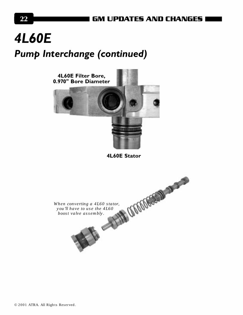
�������%��& ����'� (�The non-PWM (pulse width modulated) pumps that were used only in the 93 to 94 model4L60E are almost identical to the earlier 4L60 pumps. The main differences are the4L60E pump stators don’t have the D2 boost circuit drilled, and the bore for the filter islarger.
In fact, because the non-PWM pumps are becoming increasingly harder to find, someparts remanufacturers have been machining the filter bores of 4L60 stators to meet thedemands. This works, if done properly, but there are a few more things you will need todo:
� ��������������������������� ��
� ���������
© 2001 ATRA. All Rights Reserved.
�������������� �����
�������%��& ����'� (����� �� ���
� ����������
When converting a 4L60 stator,you’ll have to use the 4L60boost valve assembly.
� ����������������!����������� ��

�������������� ���
© 2001 ATRA. All Rights Reserved.
��
�������%��& ����'� (����� �� ��� Make sure the D2 boost circuit has the necessary exhaust: Drill a vent hole about 1/8"diameter in the D2 boost passage.
If the stator was from a unit with an auxiliary valve body, plug the forward feed tubepassage.
If you’re using a 4L60 stator,drill a 1/8" hole in the D2 boostpassage for an exhaust.
�
If you’re using the statorfrom a unit with an auxiliaryvalve body, plug the for-ward feed tube passage.
© 2001 ATRA. All Rights Reserved.
�������������� �����
"�#�$%������� �$%�������
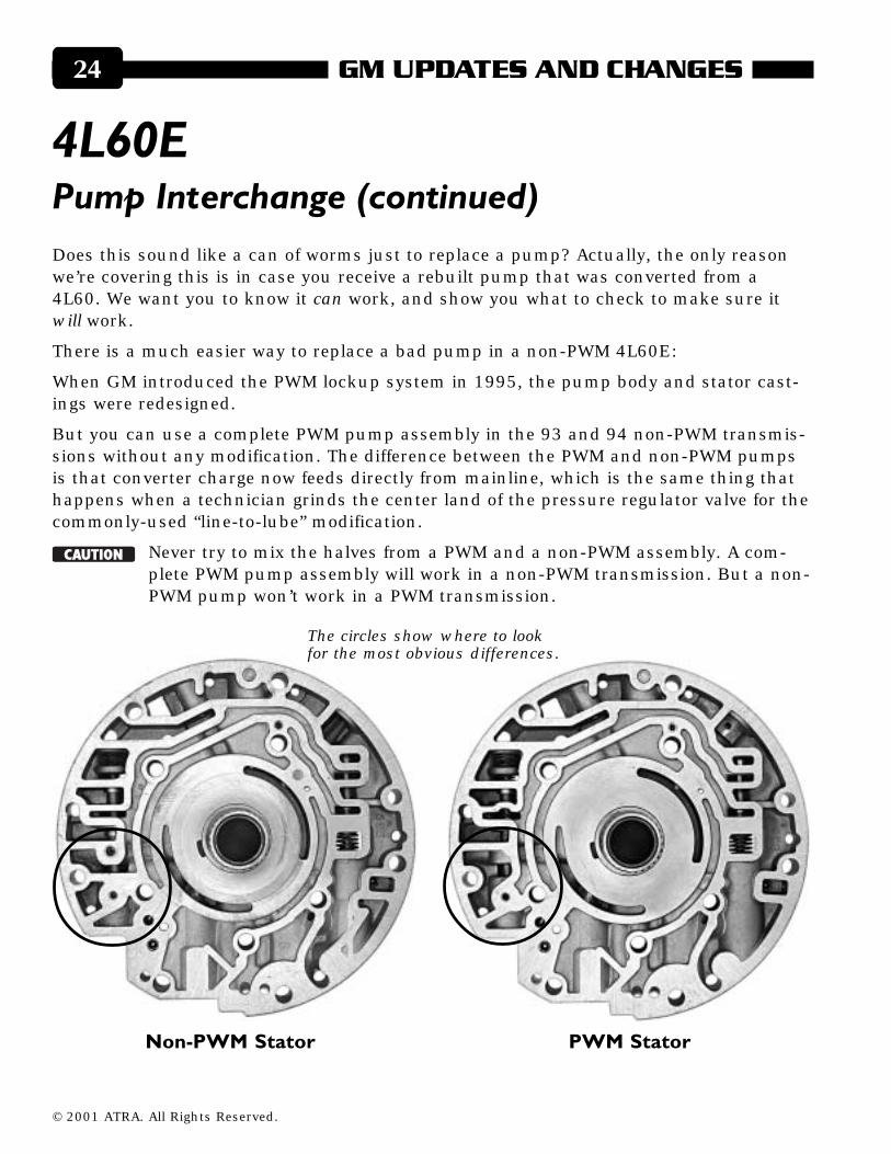
The circles show where to lookfor the most obvious differences.
Does this sound like a can of worms just to replace a pump? Actually, the only reasonwe’re covering this is in case you receive a rebuilt pump that was converted from a4L60. We want you to know it can work, and show you what to check to make sure itwill work.
There is a much easier way to replace a bad pump in a non-PWM 4L60E:
When GM introduced the PWM lockup system in 1995, the pump body and stator cast-ings were redesigned.
But you can use a complete PWM pump assembly in the 93 and 94 non-PWM transmis-sions without any modification. The difference between the PWM and non-PWM pumpsis that converter charge now feeds directly from mainline, which is the same thing thathappens when a technician grinds the center land of the pressure regulator valve for thecommonly-used “line-to-lube” modification.
� � � � � � Never try to mix the halves from a PWM and a non-PWM assembly. A com-plete PWM pump assembly will work in a non-PWM transmission. But a non-PWM pump won’t work in a PWM transmission.
�������%��& ����'� (����� �� ���

�������������� ���
© 2001 ATRA. All Rights Reserved.
��
���������� ������������ ������
������������ ������������
The circles show where to lookfor the most obvious differences.