cases and motherboards
TRANSCRIPT

Copyright © 2002 Heathkit Company, Inc. All rights reserved.
Unit 2
Cases and
Motherboards
2
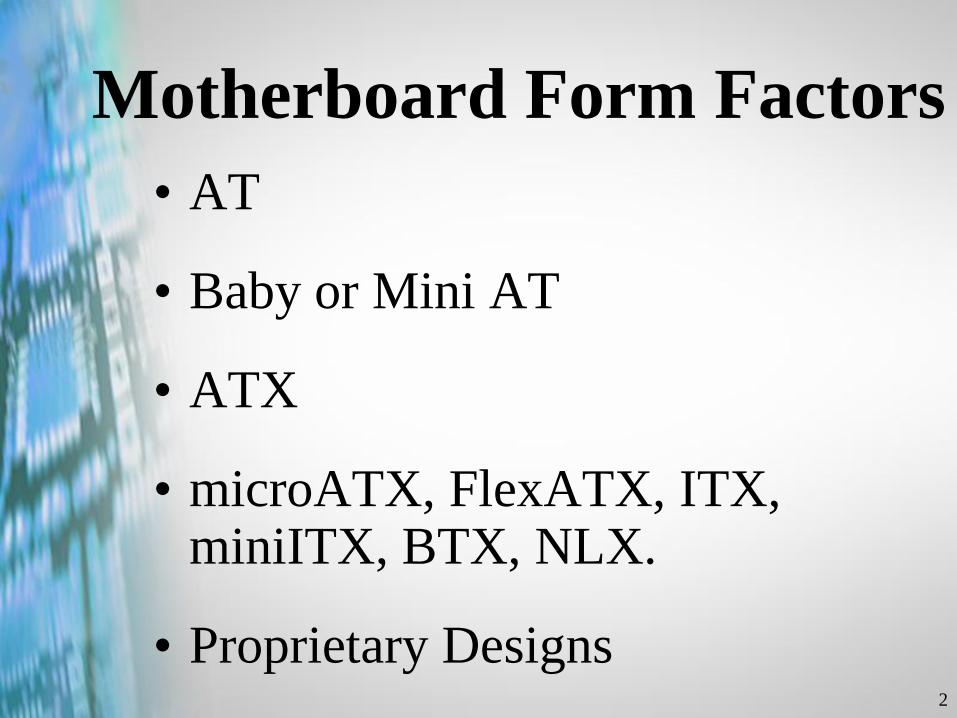
Motherboard Form Factors
• AT
• Baby or Mini AT
• ATX
• microATX, FlexATX, ITX, miniITX, BTX, NLX.
• Proprietary Designs
3
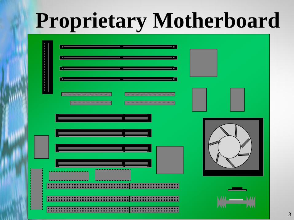
Proprietary Motherboard
4
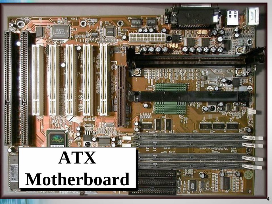
ATX
Motherboard
5
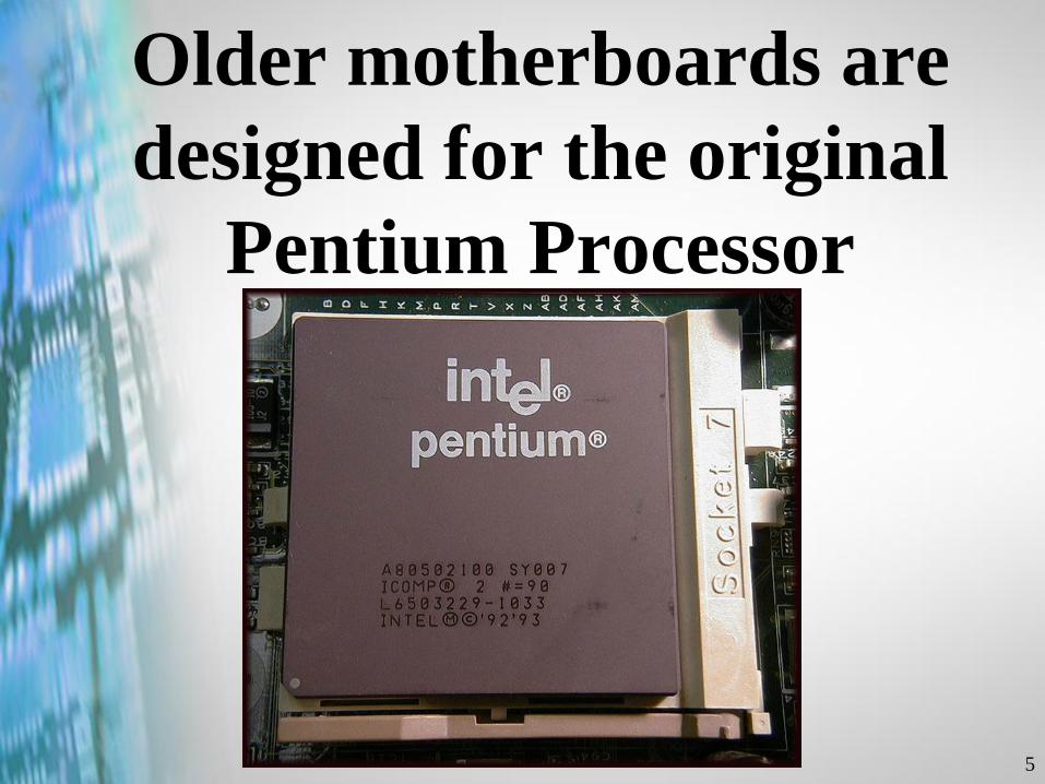
Older motherboards are
designed for the original
Pentium Processor
6
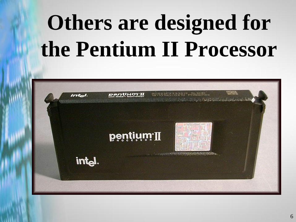
Others are designed for
the Pentium II Processor
7
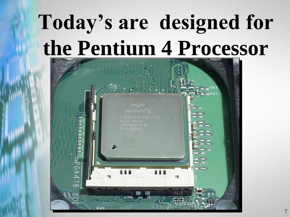
Today’s are designed for
the Pentium 4 Processor
8
Motherboard Form
Factors
•AT-Type
•ATX-Type
9
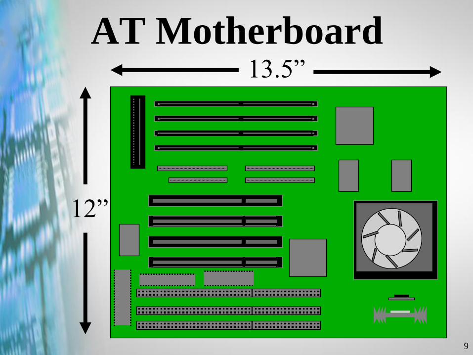
AT Motherboard
12”
13.5”
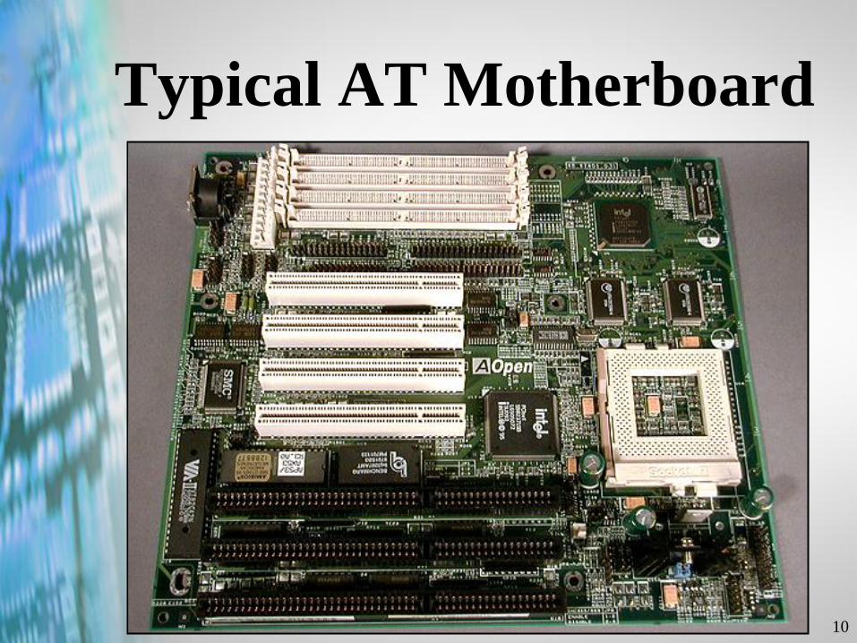
10
Typical AT Motherboard
11
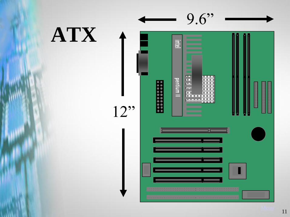
ATX9.6”
12”
Menu
12
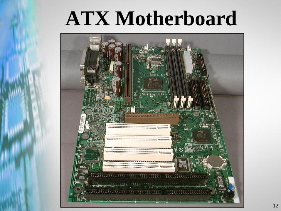
ATX Motherboard
13
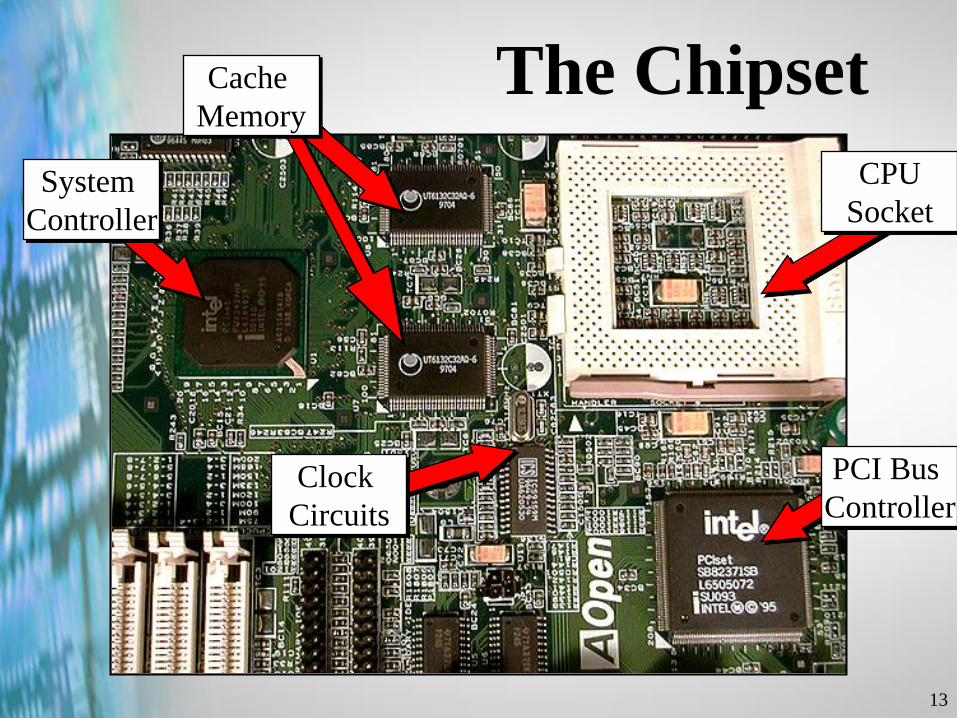
The ChipsetCache
Memory
System
Controller
PCI Bus
Controller
CPU
Socket
Clock
Circuits
14
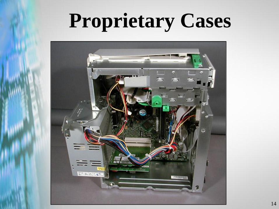
Proprietary Cases
15
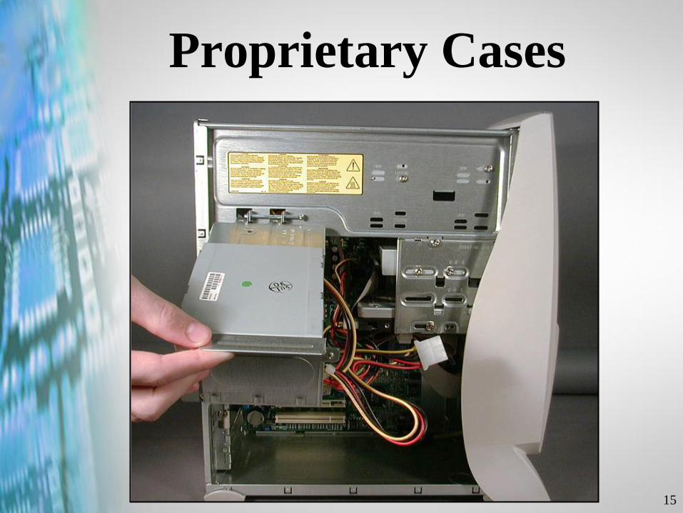
Proprietary Cases

16
Proprietary Cases
17
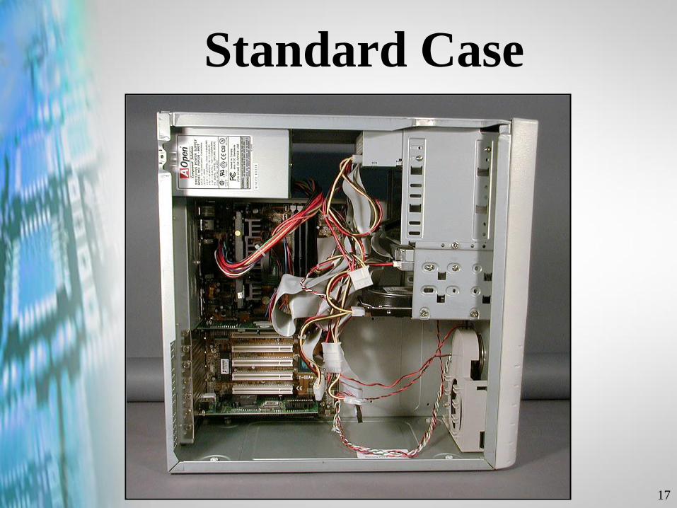
Standard Case

Copyright © 2002 Heathkit Company, Inc. All rights reserved.
The ROM/BIOS
19
Setup vs. BIOS vs. CMOS
Setup is a program that
controls settings in the BIOS,
which are stored on a device
manufactured with CMOS
technology.

20
Setup lets you
control how your
computer is
configured.

21
When you get a new
computer, it is a good
idea to write down
the configuration
information.
22
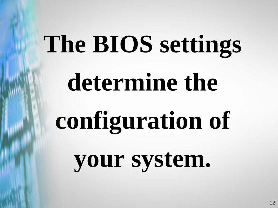
The BIOS settings
determine the
configuration of
your system.

23
This information is
saved in a special
memory called
CMOS.
24
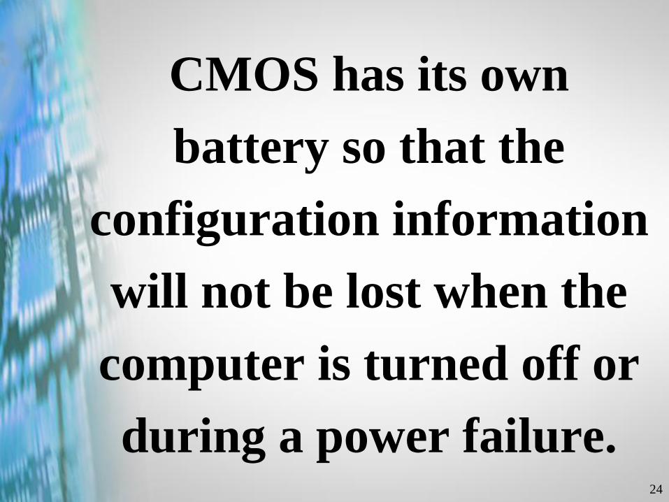
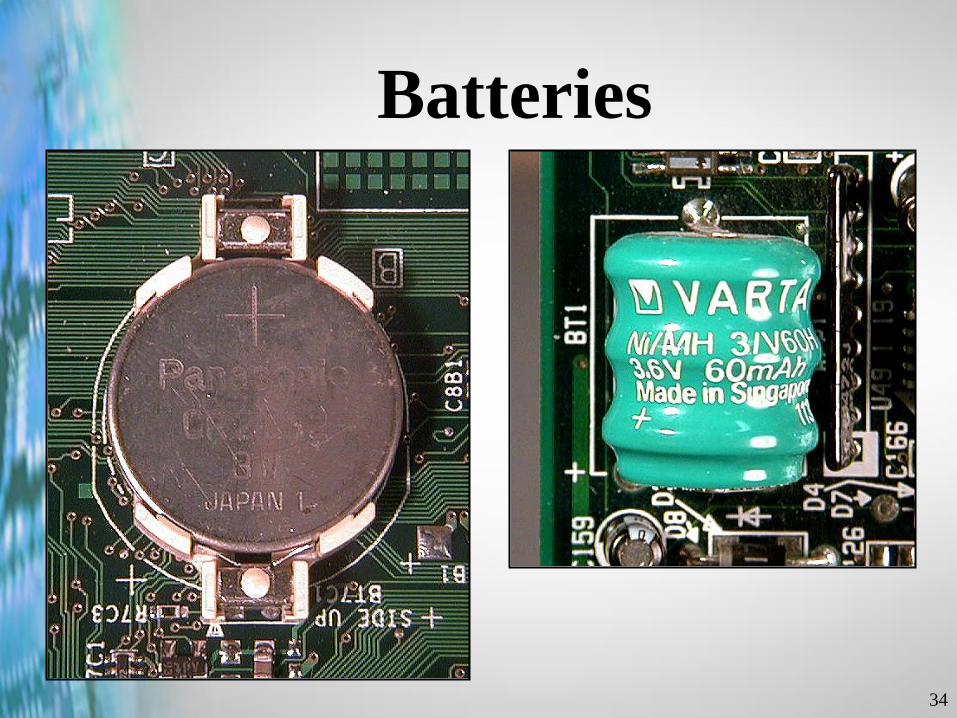
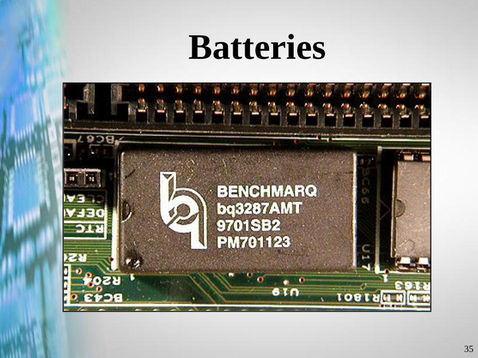
CMOS has its own
battery so that the
configuration information
will not be lost when the
computer is turned off or
during a power failure.

25
BIOS Suppliers
• Award
• American Megatrends (AMI)
• Phoenix
26
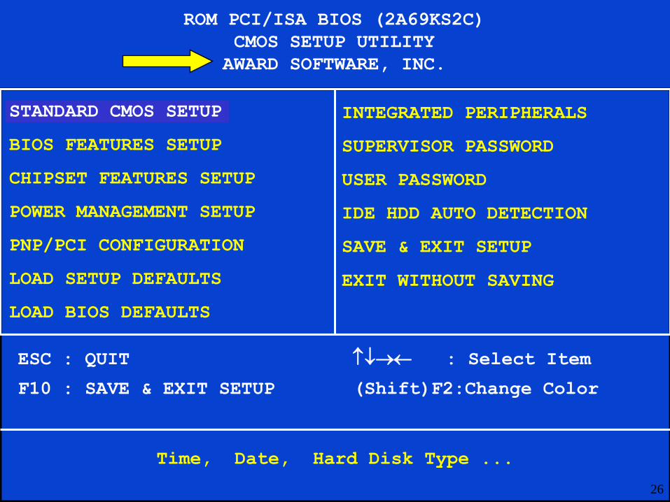
ROM PCI/ISA BIOS (2A69KS2C)
CMOS SETUP UTILITY
AWARD SOFTWARE, INC.
STANDARD CMOS SETUP
BIOS FEATURES SETUP
CHIPSET FEATURES SETUP
POWER MANAGEMENT SETUP
PNP/PCI CONFIGURATION
LOAD SETUP DEFAULTS
LOAD BIOS DEFAULTS
INTEGRATED PERIPHERALS
SUPERVISOR PASSWORD
USER PASSWORD
IDE HDD AUTO DETECTION
SAVE & EXIT SETUP
EXIT WITHOUT SAVING
ESC : QUIT : Select Item
F10 : SAVE & EXIT SETUP (Shift)F2:Change Color
Time, Date, Hard Disk Type ...
27
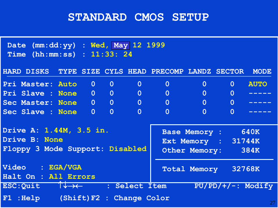
STANDARD CMOS SETUP
Date (mm:dd:yy) : Wed, May 12 1999
Time (hh:mm:ss) : 11:33: 24
HARD DISKS TYPE SIZE CYLS HEAD PRECOMP LANDZ SECTOR MODE
Pri Master: Auto 0 0 0 0 0 0 AUTO
Pri Slave : None 0 0 0 0 0 0 -----
Sec Master: None 0 0 0 0 0 0 -----
Sec Slave : None 0 0 0 0 0 0 -----
Drive A: 1.44M, 3.5 in.
Drive B: None
Floppy 3 Mode Support: Disabled
Video : EGA/VGA
Halt On : All Errors
ESC:Quit : Select Item PU/PD/+/-: Modify
F1 :Help (Shift)F2 : Change Color
Base Memory : 640K
Ext Memory : 31744K
Other Memory: 384K
Total Memory 32768K
28
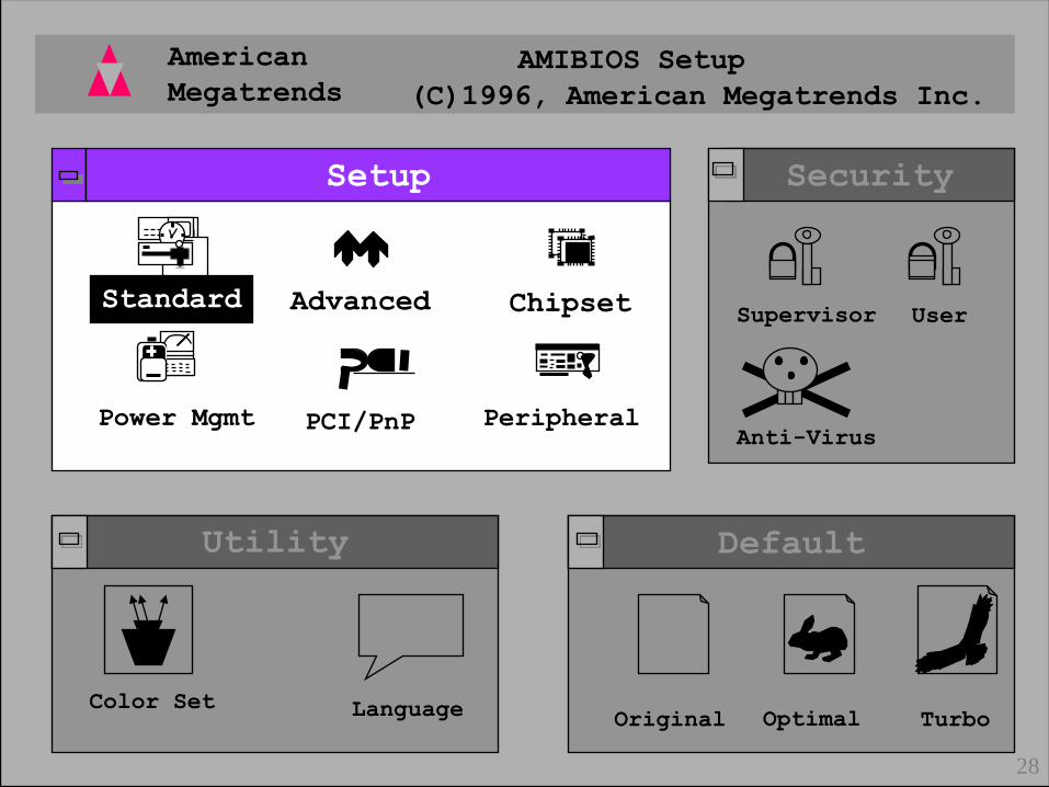
American
Megatrends
AMIBIOS Setup
(C)1996, American Megatrends Inc.
Default
Original Optimal Turbo
Utility
Color Set Language
Security
Supervisor User
Anti-Virus
28
Setup
1
7Standard
PCI/PnP
Advanced
PeripheralPower Mgmt
Chipset
29
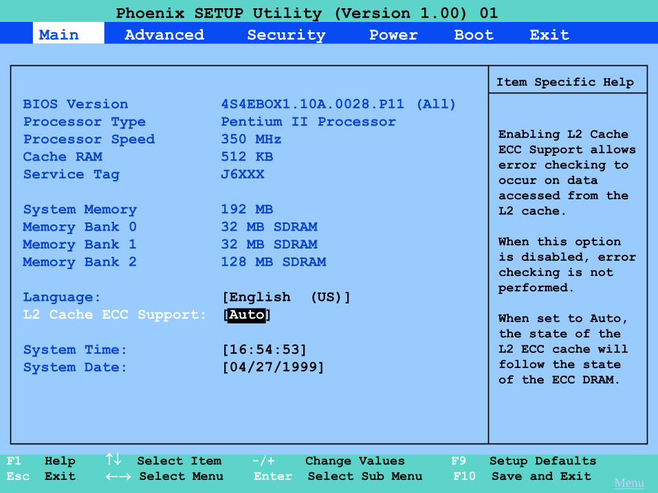
Main Advanced Security Power Boot Exit
Phoenix SETUP Utility (Version 1.00) 01
F1 Help Select Item -/+ Change Values F9 Setup Defaults
Esc Exit Select Menu Enter Select Sub Menu F10 Save and Exit
Item Specific Help
BIOS Version 4S4EBOX1.10A.0028.P11 (All)
Processor Type Pentium II Processor
Processor Speed 350 MHz
Cache RAM 512 KB
Service Tag J6XXX
System Memory 192 MB
Memory Bank 0 32 MB SDRAM
Memory Bank 1 32 MB SDRAM
Memory Bank 2 128 MB SDRAM
Language: [English (US)]
L2 Cache ECC Support: [Auto]
System Time: [16:54:53]
System Date: [04/27/1999]
Enabling L2 Cache
ECC Support allows
error checking to
occur on data
accessed from the
L2 cache.
When this option
is disabled, error
checking is not
performed.
When set to Auto,
the state of the
L2 ECC cache will
follow the state
of the ECC DRAM.
Menu
30
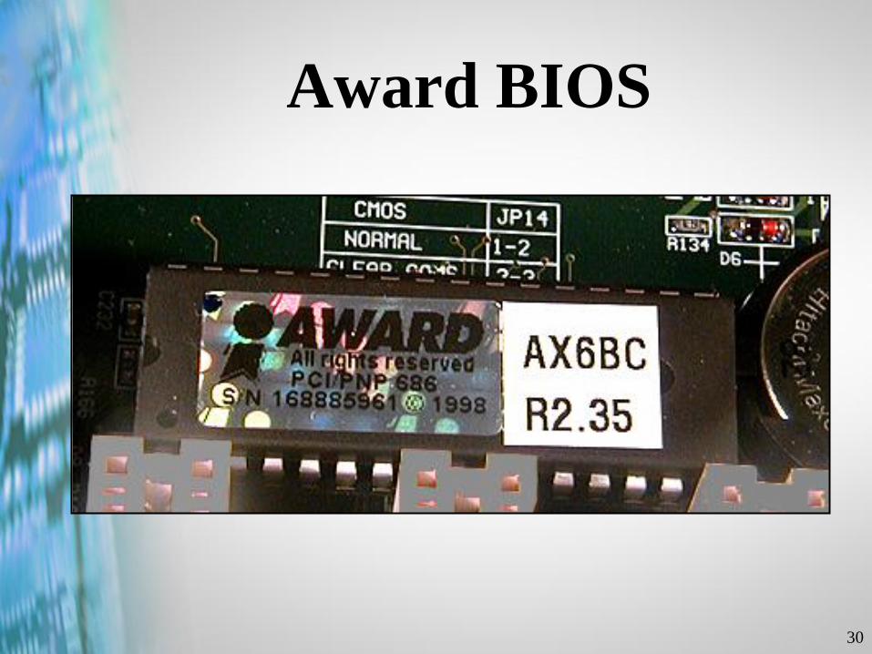
Award BIOS
31
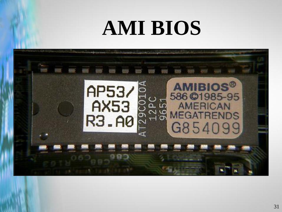
AMI BIOS
32
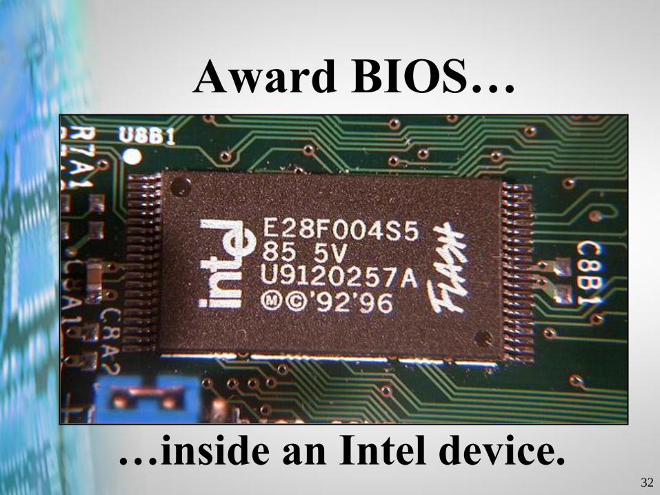
Award BIOS…
…inside an Intel device.
Copyright © 2002 Heathkit Company, Inc. All rights reserved.
Maintaining BIOS
Configuration
Information
34
Batteries
35
Batteries

Copyright © 2002 Heathkit Company, Inc. All rights reserved.
Power-On Self
Test

37
A program cannot be
loaded into memory unless
a program has already been
loaded into memory.

38
Cold Boot
vs.
Warm Boot
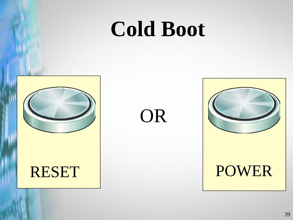
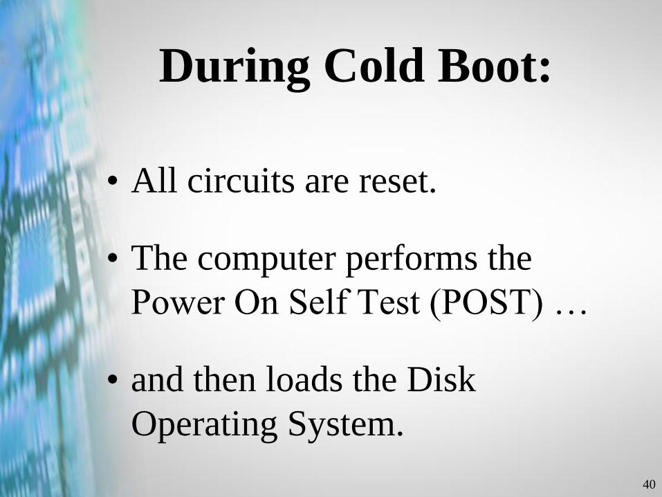
39
Cold Boot
RESET POWER
OR
40
During Cold Boot:
• All circuits are reset.
• The computer performs the
Power On Self Test (POST) …
• and then loads the Disk
Operating System.
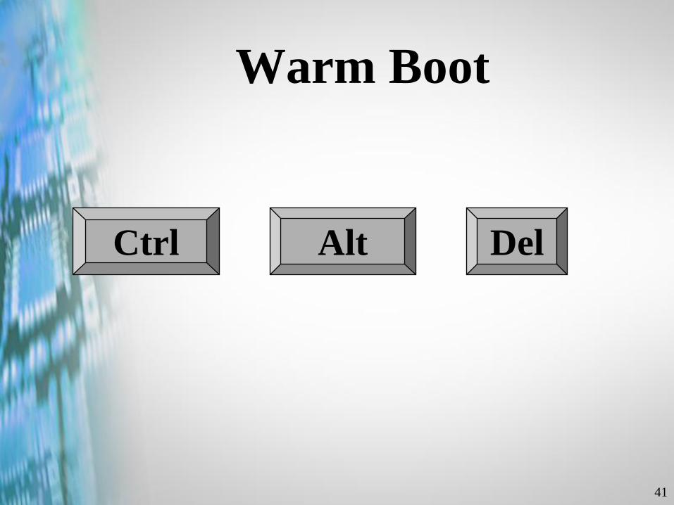
41
Warm Boot
Ctrl Alt Del

42
During Warm Boot:
• The computer skips the Power On
Self Test (POST) …
• and immediately reloads the OS.
43
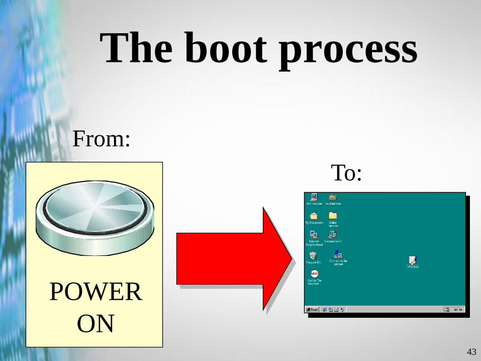
The boot process
POWER
ON
From:
To:
C:\>

44
The Boot Process
• Activate the Power On Self Test
(POST)
• Load the OS
45
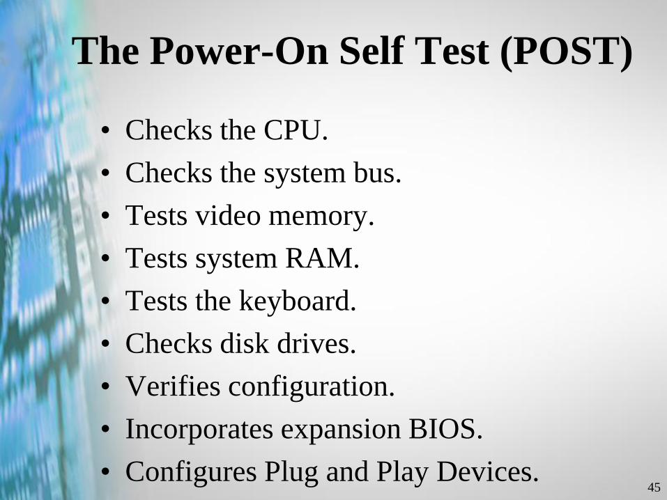
The Power-On Self Test (POST)
• Checks the CPU.
• Checks the system bus.
• Tests video memory.
• Tests system RAM.
• Tests the keyboard.
• Checks disk drives.
• Verifies configuration.
• Incorporates expansion BIOS.
• Configures Plug and Play Devices.

46
The CPU checks itself
47
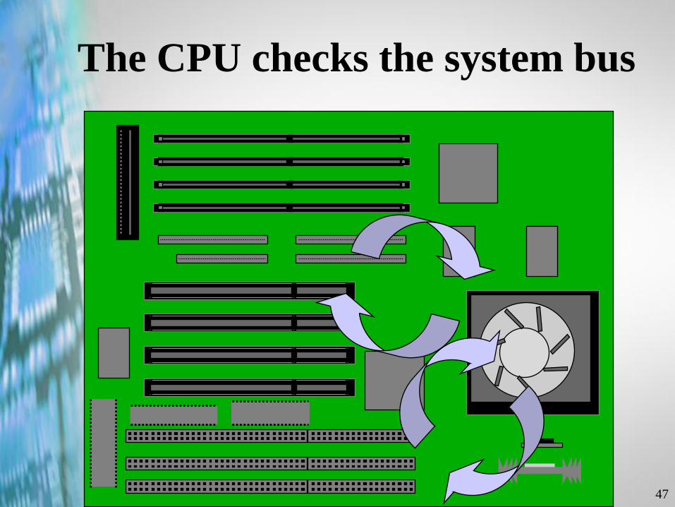
The CPU checks the system bus
48
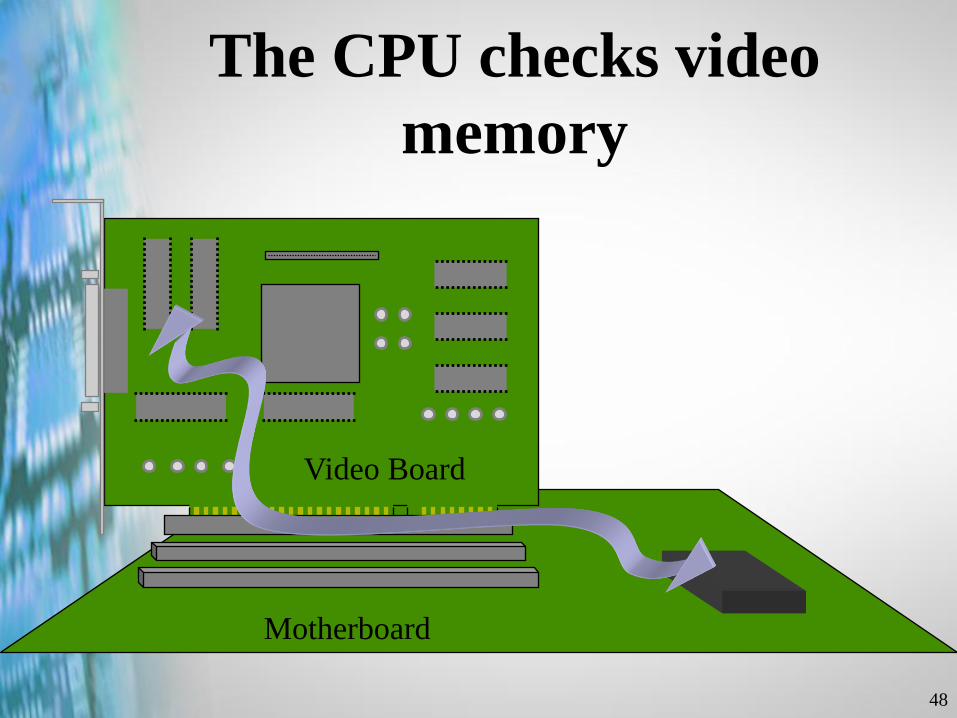
The CPU checks video
memory
Motherboard
Video Board
49
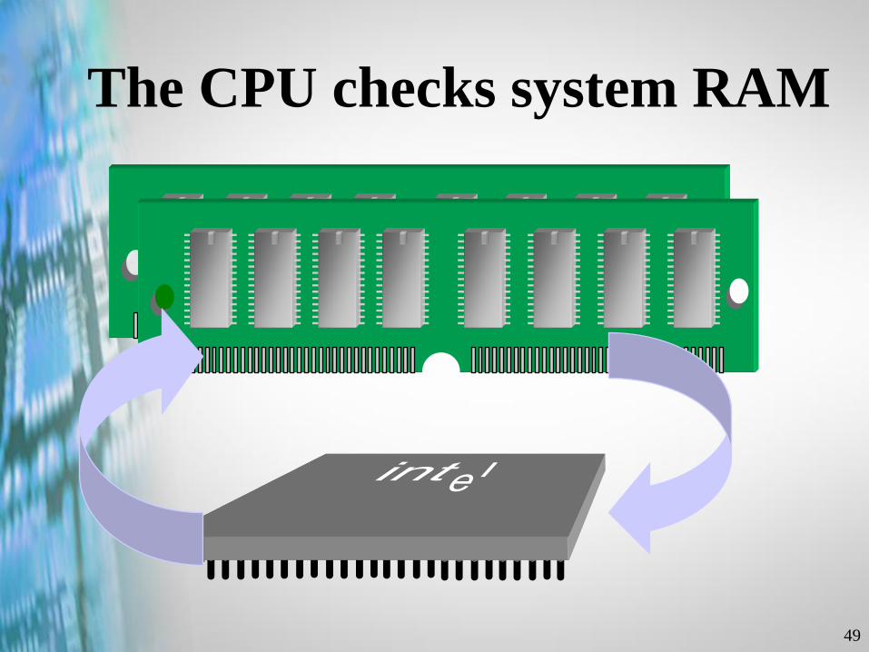
The CPU checks system RAM
50
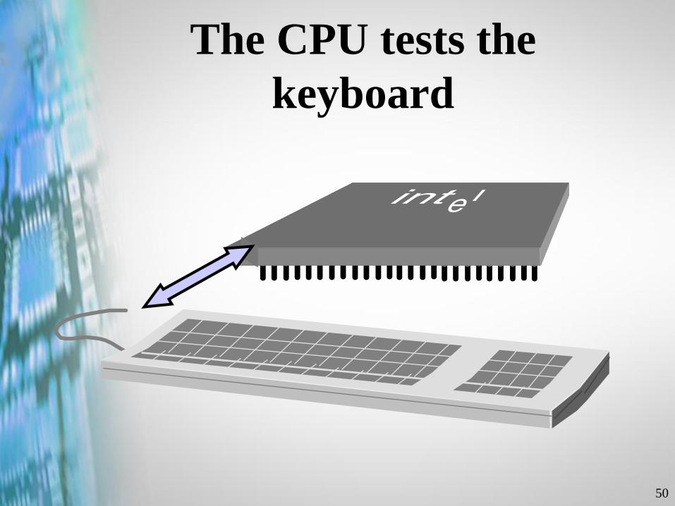
The CPU tests the
keyboard
51
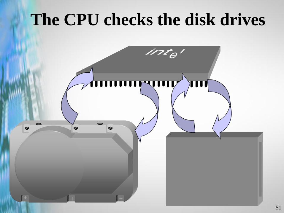
The CPU checks the disk drives
52
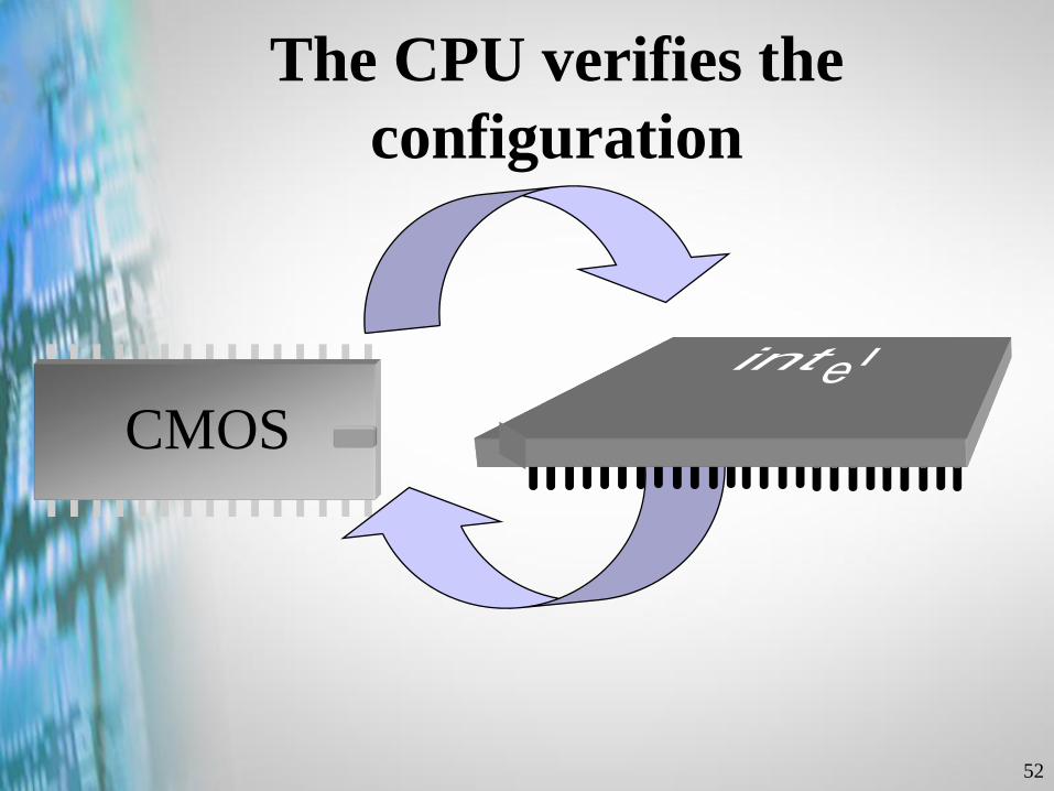
The CPU verifies the
configuration
CMOS
53
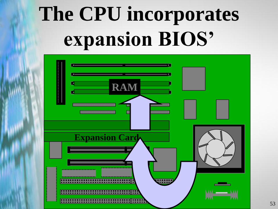
The CPU incorporates
expansion BIOS’
Expansion Card
RAM
54
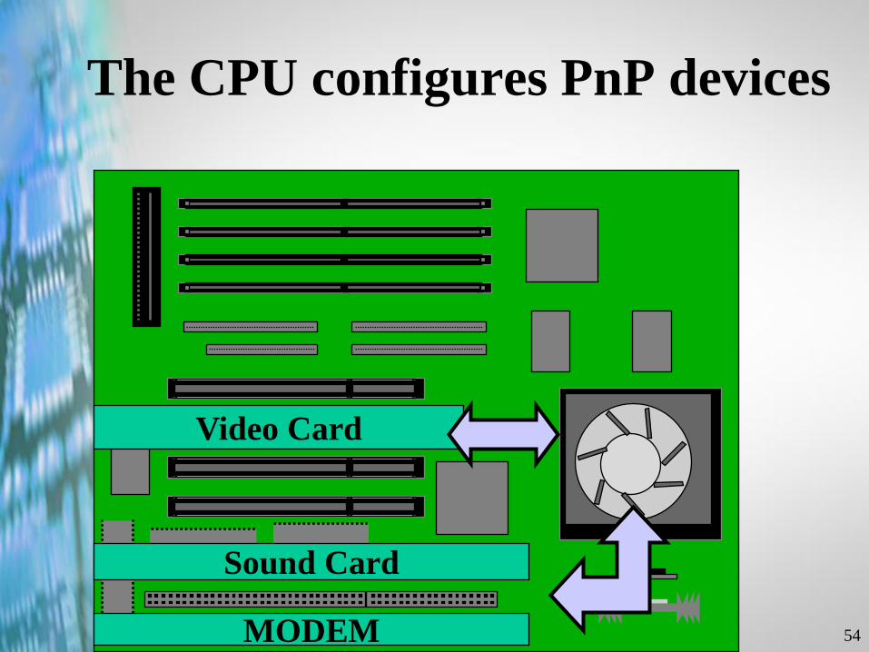
The CPU configures PnP devices
Video Card
Sound Card
MODEM
55
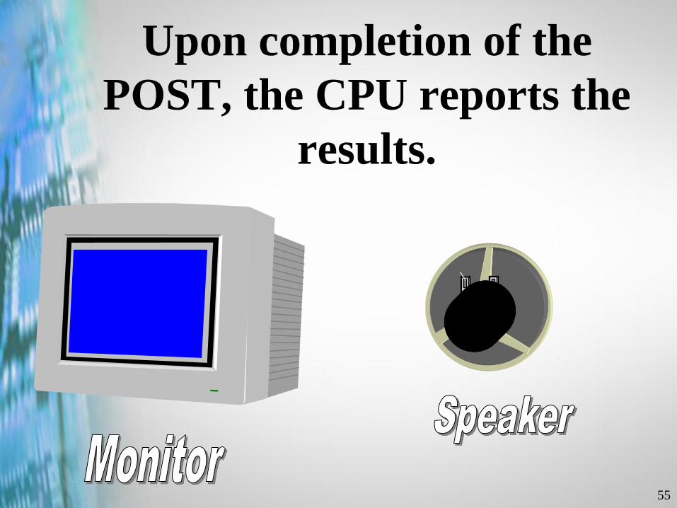
Upon completion of the
POST, the CPU reports the
results.

56
The Boot Process
• Activate the Power On Self Test
(POST)
• Load the OS

Copyright © 2002 Heathkit Company, Inc. All rights reserved.
Memory Types
and History

58
DRAMDynamic Random Access Memory
• More $$ than hard drive memory, but faster
• The number used to sell the machine
• Require constant refreshing
• Power off = Data lost (volatile)
59
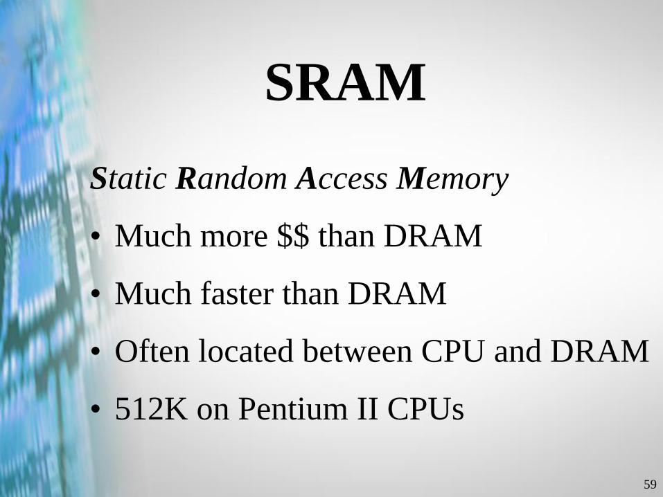
SRAM
Static Random Access Memory
• Much more $$ than DRAM
• Much faster than DRAM
• Often located between CPU and DRAM
• 512K on Pentium II CPUs
60
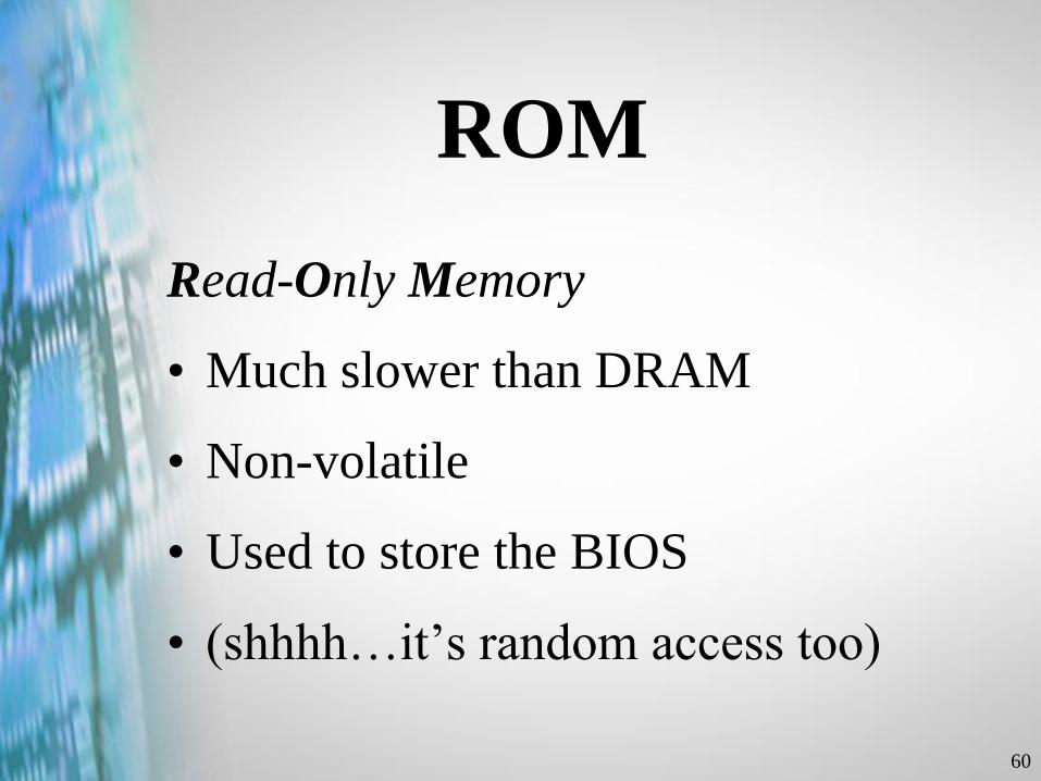
ROM
Read-Only Memory
• Much slower than DRAM
• Non-volatile
• Used to store the BIOS
• (shhhh…it’s random access too)
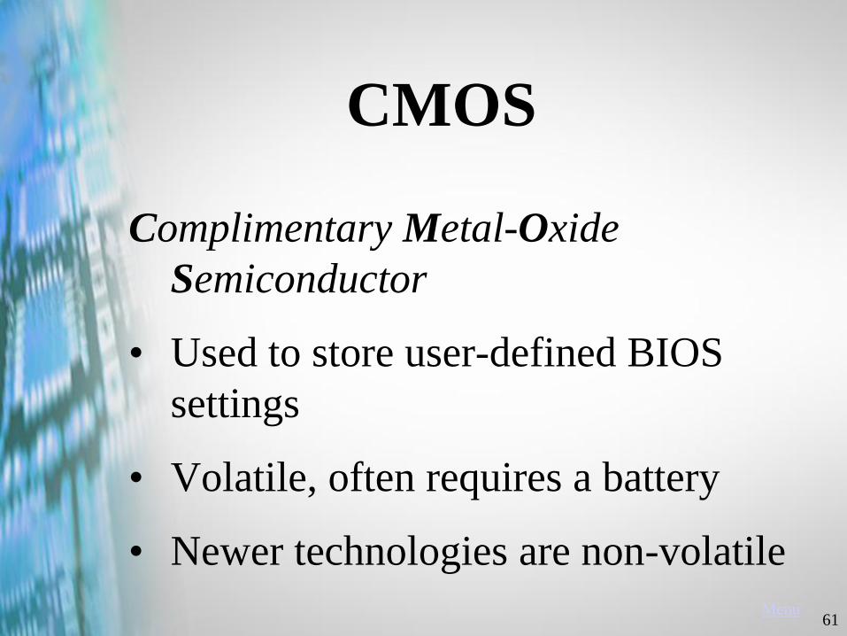
61Menu
CMOS
Complimentary Metal-Oxide
Semiconductor
• Used to store user-defined BIOS
settings
• Volatile, often requires a battery
• Newer technologies are non-volatile

Copyright © 2002 Heathkit Company, Inc. All rights reserved.
Computer
Memory Devices
63
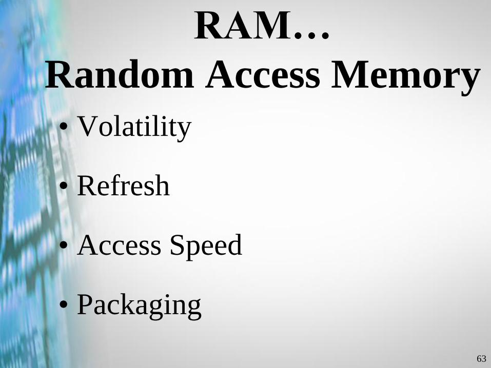
RAM…
Random Access Memory
• Volatility
• Refresh
• Access Speed
• Packaging
64
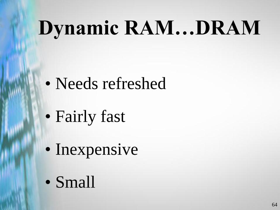
Dynamic RAM…DRAM
• Needs refreshed
• Fairly fast
• Inexpensive
• Small
65
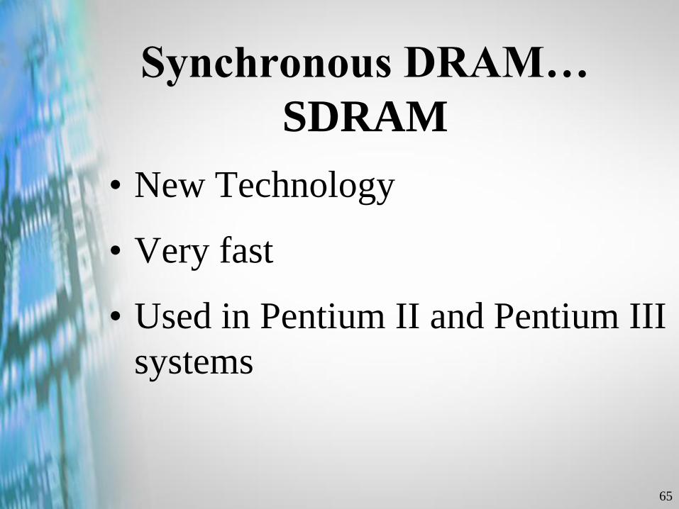
Synchronous DRAM…
SDRAM
• New Technology
• Very fast
• Used in Pentium II and Pentium III
systems

66
Static RAM…SRAM
• No Refresh
• Fast
• More expensive
67
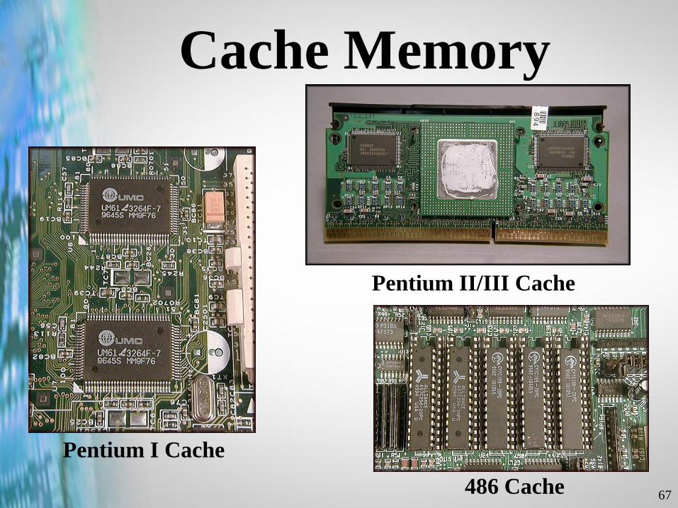
Cache Memory
Pentium I Cache
Pentium II/III Cache
486 Cache
68
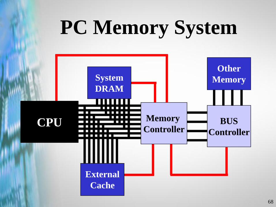
PC Memory System
CPU
External
Cache
System
DRAM
BUS
Controller
Other
Memory
Memory
Controller
69
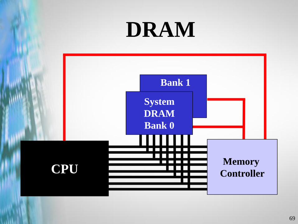
DRAM
CPUMemory
Controller
System
DRAM
Bank 0
Bank 1
70
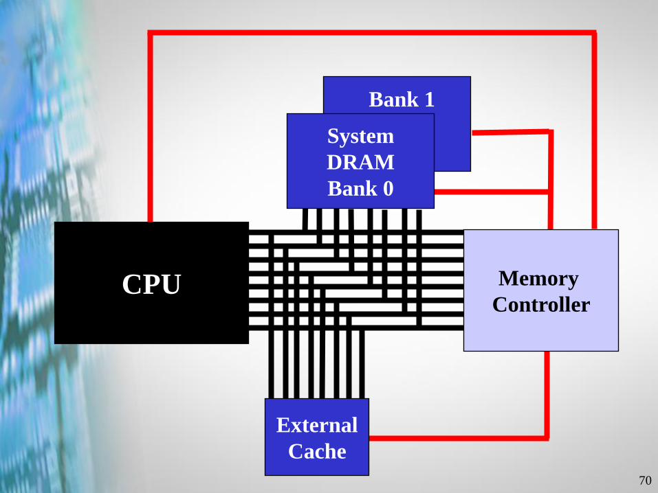
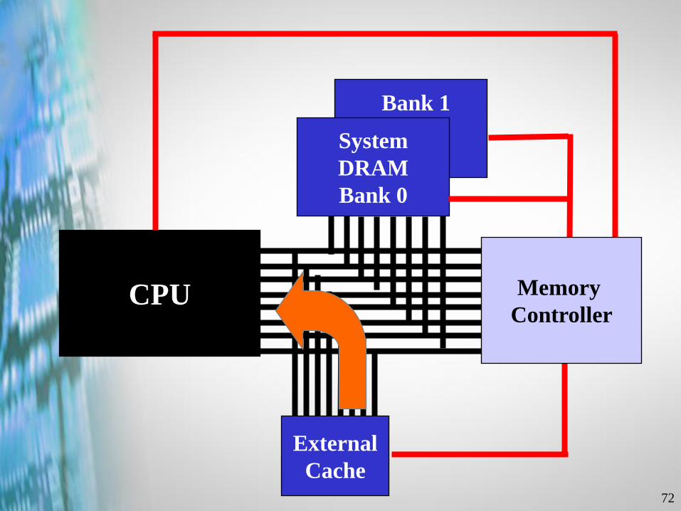
External
Cache
CPU Memory
Controller
System
DRAM
Bank 0
Bank 1
71
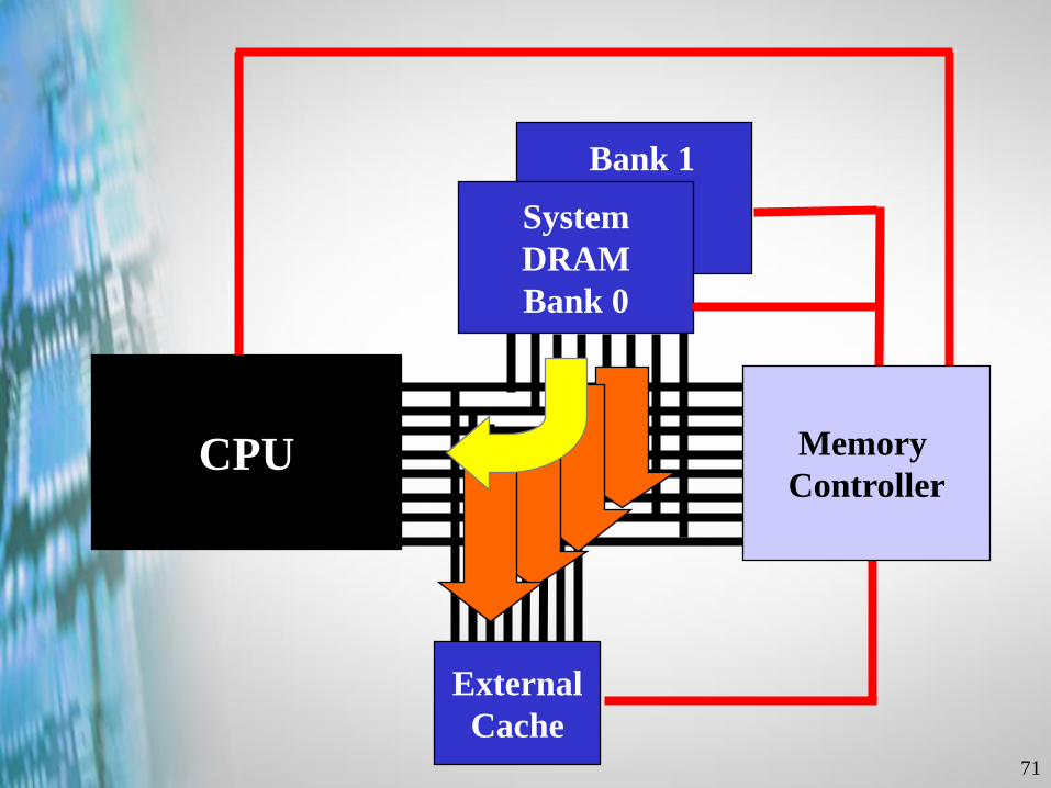
External
Cache
CPU
System
DRAM
Bank 0
Bank 1
Memory
Controller
72
External
Cache
CPU
System
DRAM
Bank 0
Bank 1
Memory
Controller
73
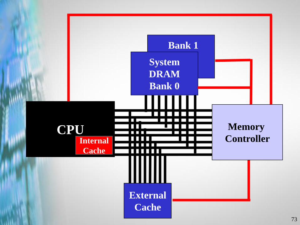
External
Cache
CPU
System
DRAM
Bank 0
Bank 1
Memory
ControllerInternal
Cache
74
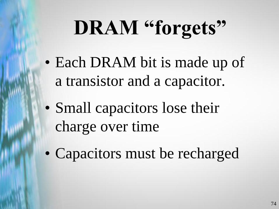
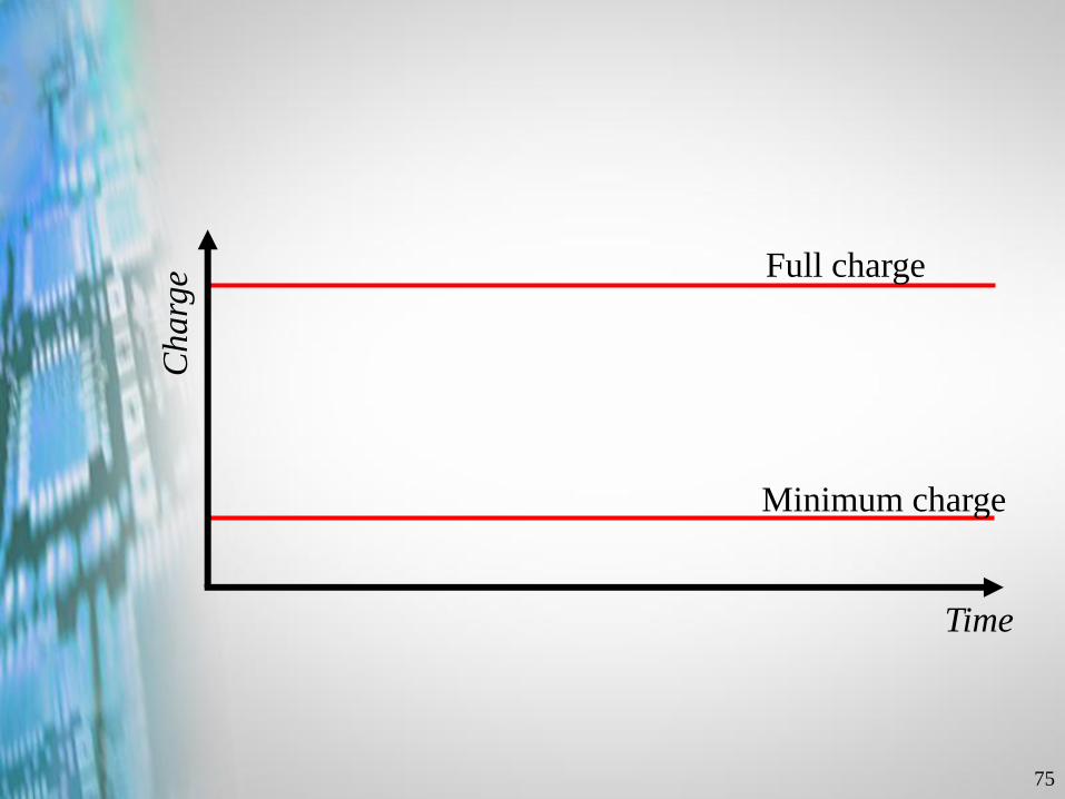
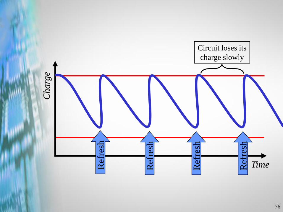
DRAM “forgets”
• Each DRAM bit is made up of
a transistor and a capacitor.
• Small capacitors lose their
charge over time
• Capacitors must be recharged
75
Charg
e
Time
Full charge
Minimum charge
76
Charg
e
TimeRef
resh
Ref
resh
Ref
resh
Ref
resh
Circuit loses its
charge slowly

Copyright © 2002 Heathkit Company, Inc. All rights reserved.
Working with
Memory
78
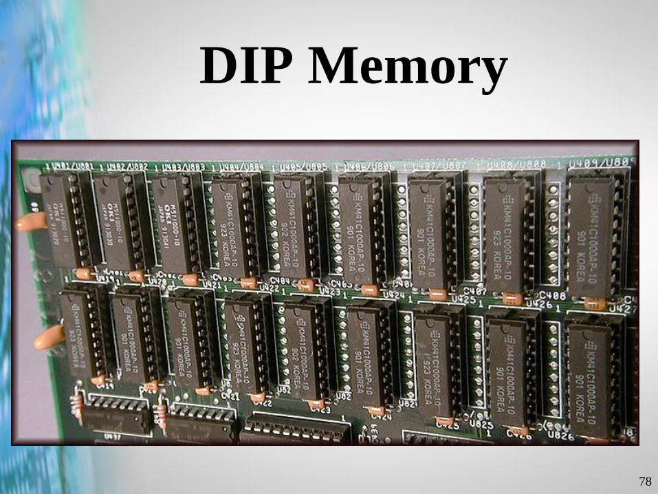
DIP Memory

79
Programmable Read-
Only Memory...PROM
• Non-Volatile
• Slow
• Difficult to Change
• Expensive
80
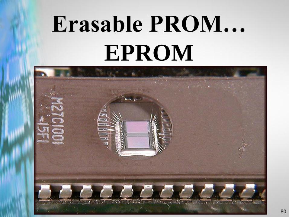
Erasable PROM…
EPROM
81
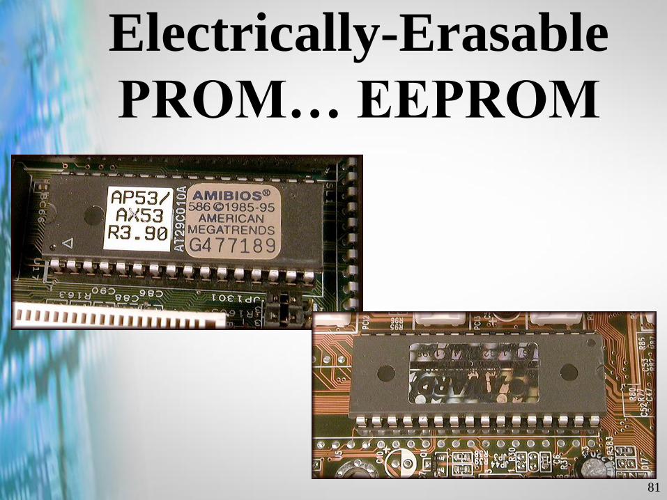
Electrically-Erasable
PROM… EEPROM
82
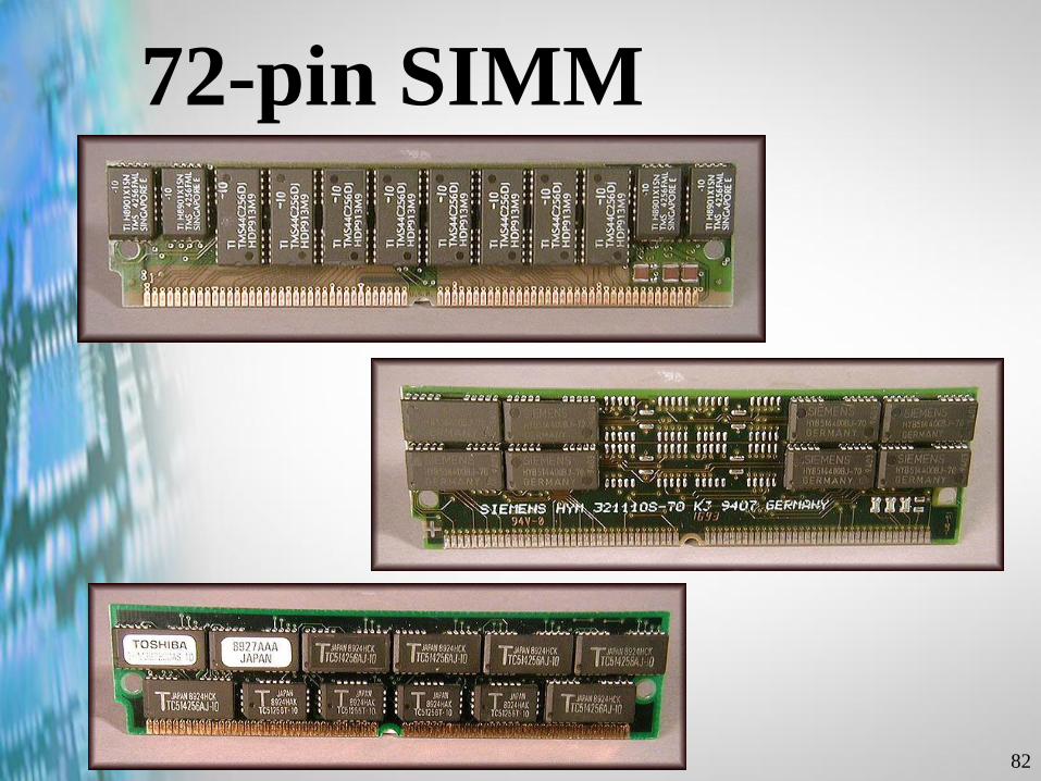
72-pin SIMM
83
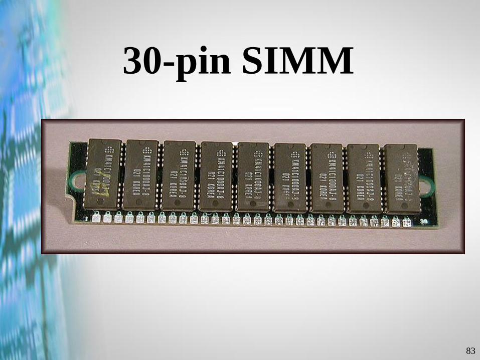
30-pin SIMM
84
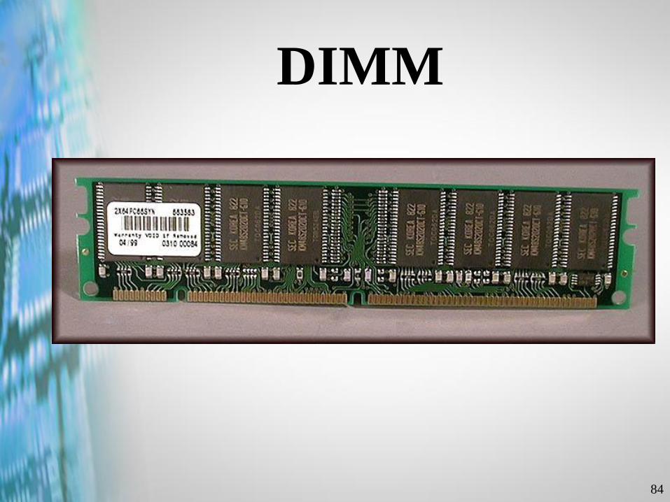
DIMM
85
Video RAM (VRAM)
Windows RAM (WRAM)
SGRAM
86
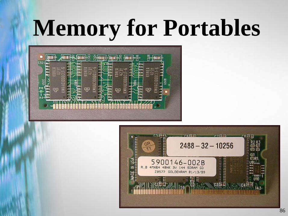
Memory for Portables
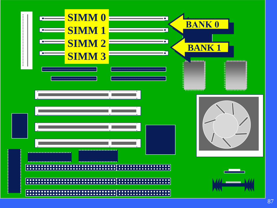
SIMM 0
SIMM 1
SIMM 2
SIMM 3BANK 1
87
88
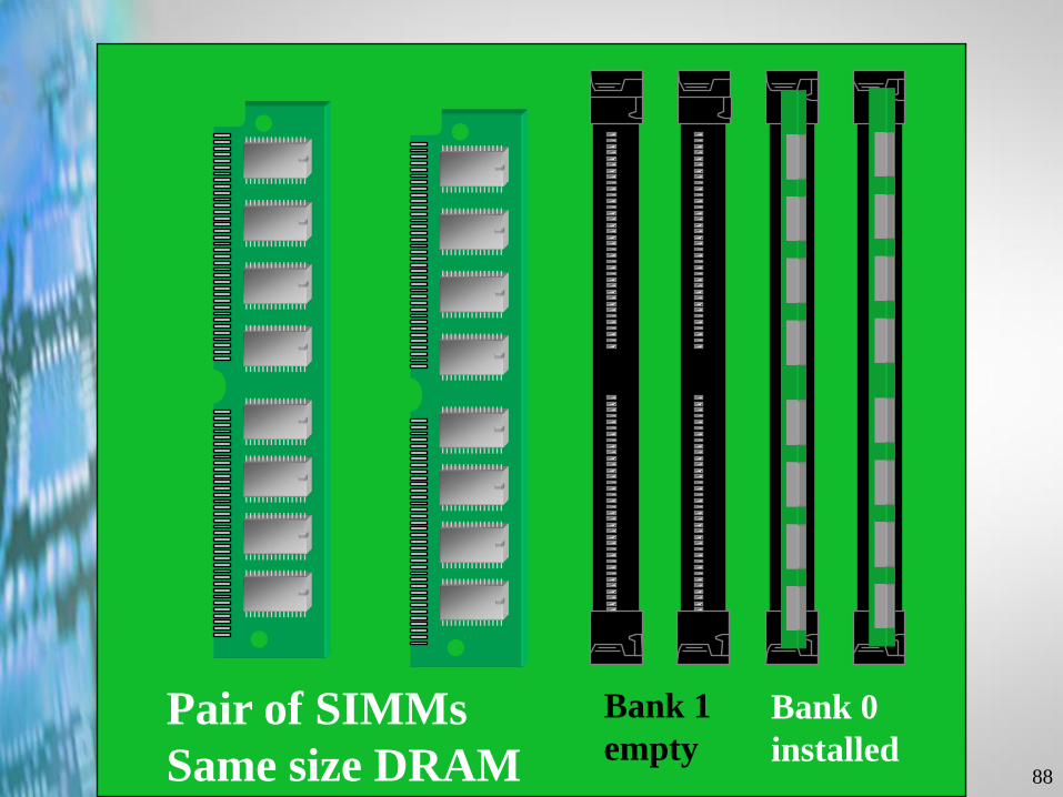
Bank 0
installed
Bank 1
emptyPair of SIMMs
Same size DRAM
89
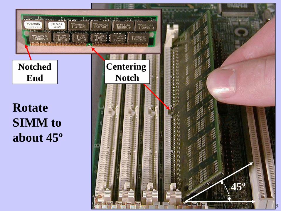
Rotate
SIMM to
about 45º
45º
Centering
Notch
Notched
End
90
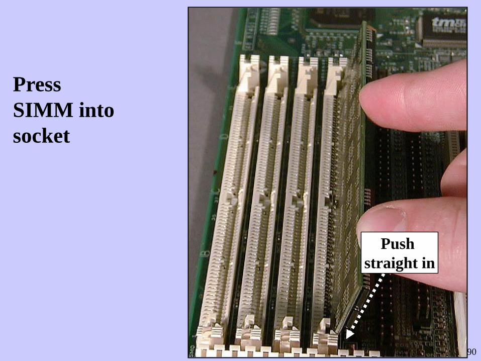
Press
SIMM into
socket
Push
straight in
91
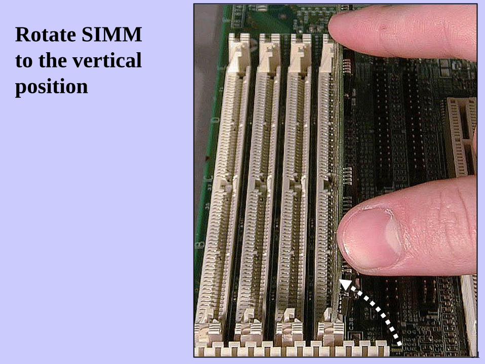
Rotate SIMM
to the vertical
position
92
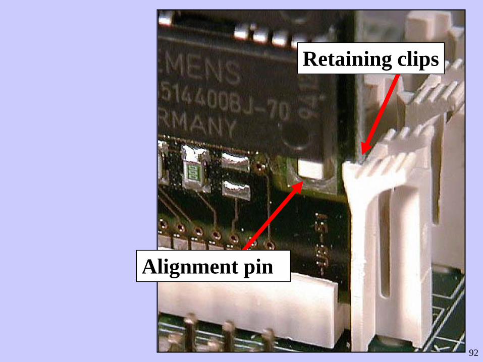
Alignment pin
Retaining clips
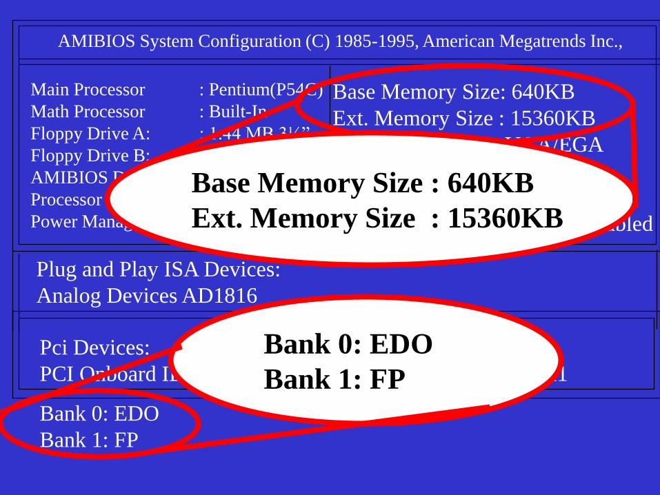
AMIBIOS System Configuration (C) 1985-1995, American Megatrends Inc.,
Main Processor : Pentium(P54C)
Math Processor : Built-In
Floppy Drive A: : 1.44 MB 3½”
Floppy Drive B: : None
AMIBIOS Date : 07/15/95
Processor Clock : 100MHz
Power Management : Disabled
Base Memory Size: 640KB
Ext. Memory Size : 15360KB
Display Type : VGA/EGA
Serial Port(s) : 3F8,3E8
Parallel Port(s) : 378
External Cache : 256KB,Enabled
Plug and Play ISA Devices:
Analog Devices AD1816
Pci Devices:
PCI Onboard IDE PCI Slot 2 VGA: IRQ 11
Bank 0: EDO
Bank 1: FP
Bank 0: EDO
Bank 1: FP
Base Memory Size : 640KB
Ext. Memory Size : 15360KB
94
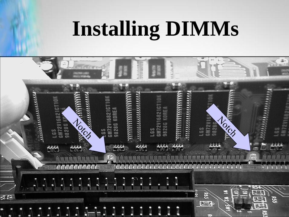
Installing DIMMs
95
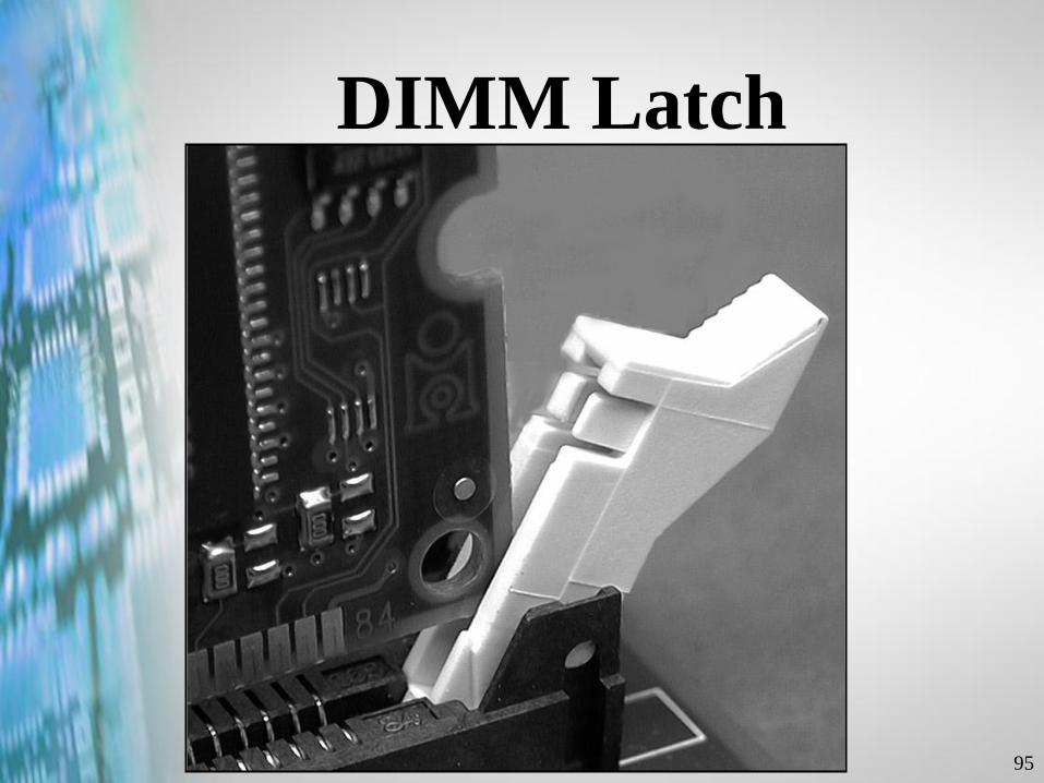
DIMM Latch
96
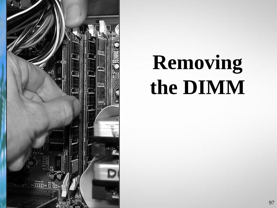
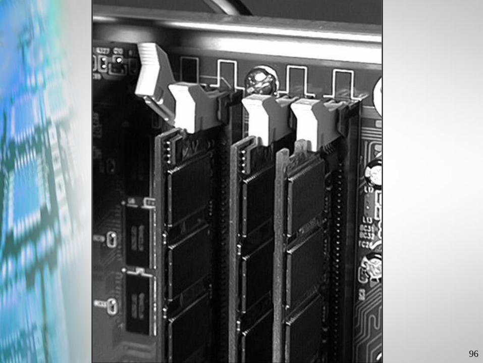
97
Removing
the DIMM