cast iron gas fired boilers models for forced · pdf filecast iron gas fired boilers ......
TRANSCRIPT
P/N 2400009005, Rev. C [09/2012]An ISO 9001-2008 Certified Company
Manufactured by:
ECR International, Inc.2201 Dwyer Avenue, Utica NY 13501web site: www.ecrinternational.com
MGB SERIES II
CAST IRON GAS FIRED BOILERS FOR FORCED HOT WATER
INSTALLATION, OPERATION & MAINTENANCE MANUAL
Models MGB-50JMGB-75J
MGB-100JMGB-125J MGB-150JMGB-170JMGB-200J
An ISO 9001-2008 Certified Company
Tested For 100 psi.ASME
Working Pressure
C.S.A. Certifi edFor Natural Gas Or Propane
2
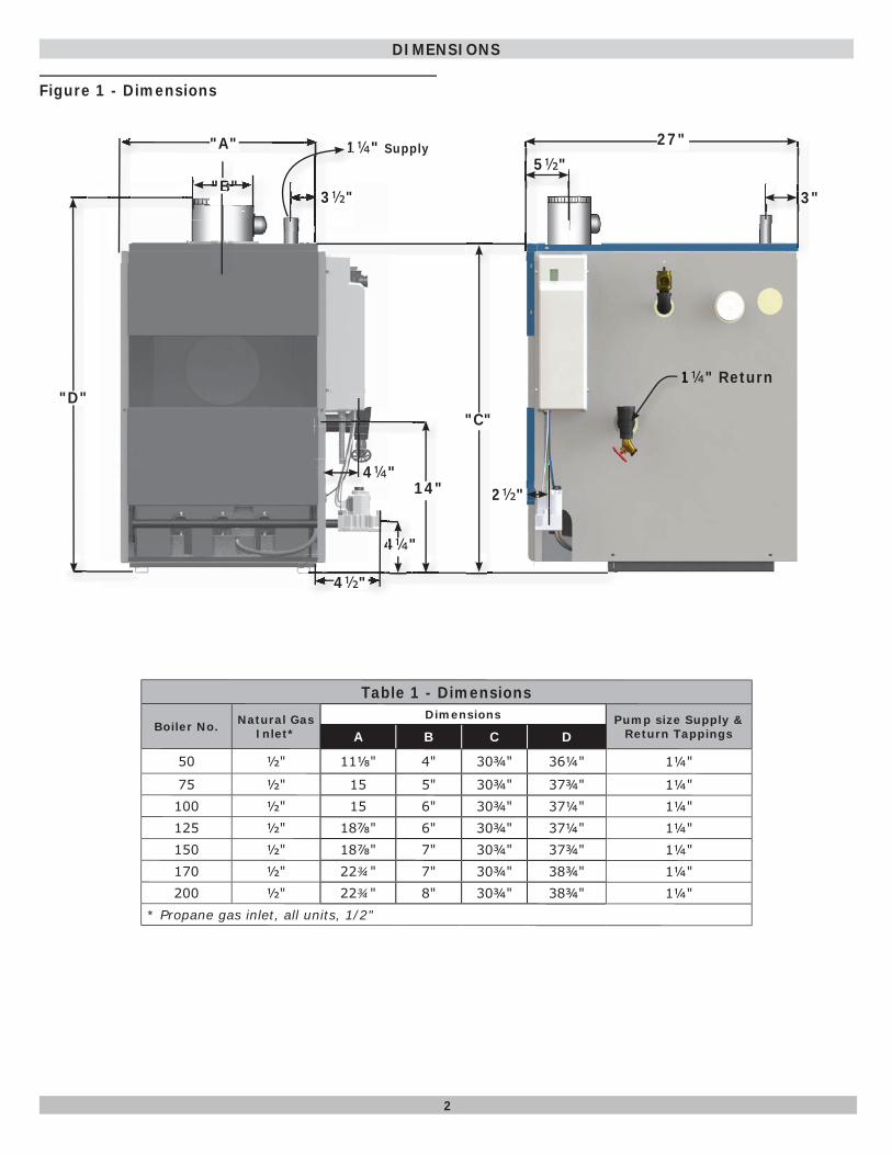
Table 1 - Dimensions
Boiler No. Natural Gas Inlet*
Dimensions Pump size Supply & Return TappingsA B C D
50 ½" 11⅛" 4" 30¾" 36¼" 1¼"
75 ½" 15 5" 30¾" 37¾" 1¼"100 ½" 15 6" 30¾" 37¼" 1¼"125 ½" 18⅞" 6" 30¾" 37¼" 1¼"150 ½" 18⅞" 7" 30¾" 37¾" 1¼"170 ½" 22¾" 7" 30¾" 38¾" 1¼"200 ½" 22¾" 8" 30¾" 38¾" 1¼"
* Propane gas inlet, all units, 1/2"
DIMENSIONS
1¼" Return1111
"B"
14"
4¼"
4¼"
1¼" Supply
2½"
"A"
" ""
"D"
44
4½"
B"BBBBBBBBBBBBBBB""""BB"BB""BBBBBBB"""BBBBBB
"C"
3½"
111
"
1
3½"
27"5½"
3"
Figure 1 - Dimensions
3
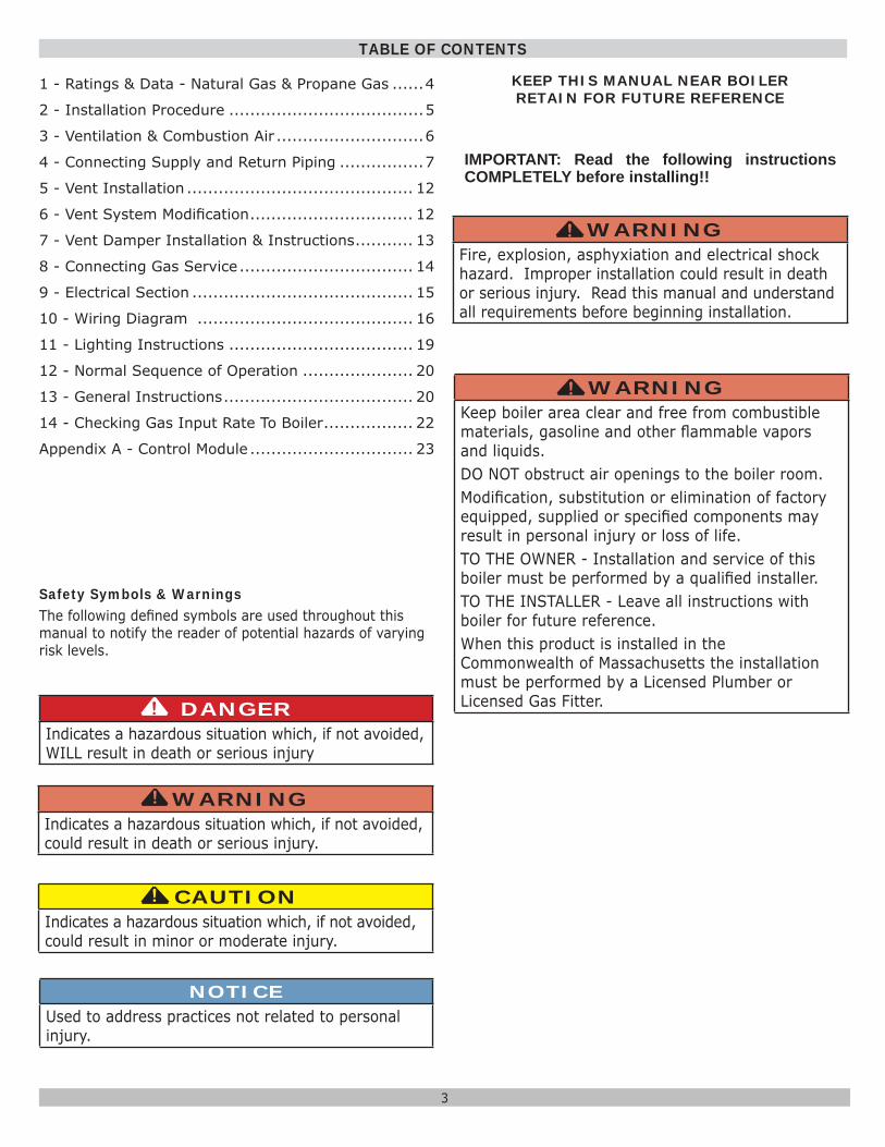
Safety Symbols & WarningsThe following defi ned symbols are used throughout this manual to notify the reader of potential hazards of varying risk levels.
1 - Ratings & Data - Natural Gas & Propane Gas ......4
2 - Installation Procedure .....................................5
3 - Ventilation & Combustion Air ............................6
4 - Connecting Supply and Return Piping ................7
5 - Vent Installation ........................................... 12
6 - Vent System Modifi cation ............................... 12
7 - Vent Damper Installation & Instructions ........... 13
8 - Connecting Gas Service ................................. 14
9 - Electrical Section .......................................... 15
10 - Wiring Diagram ......................................... 16
11 - Lighting Instructions ................................... 19
12 - Normal Sequence of Operation ..................... 20
13 - General Instructions .................................... 20
14 - Checking Gas Input Rate To Boiler ................. 22
Appendix A - Control Module ............................... 23
TABLE OF CONTENTS
NOTICEUsed to address practices not related to personal injury.
CAUTIONIndicates a hazardous situation which, if not avoided, could result in minor or moderate injury.
!!
WARNINGIndicates a hazardous situation which, if not avoided, could result in death or serious injury.
!
DANGERIndicates a hazardous situation which, if not avoided, WILL result in death or serious injury
!
IMPORTANT: Read the following instructions COMPLETELY before installing!!
KEEP THIS MANUAL NEAR BOILERRETAIN FOR FUTURE REFERENCE
WARNINGKeep boiler area clear and free from combustible materials, gasoline and other fl ammable vapors and liquids.DO NOT obstruct air openings to the boiler room.Modifi cation, substitution or elimination of factory equipped, supplied or specifi ed components may result in personal injury or loss of life.TO THE OWNER - Installation and service of this boiler must be performed by a qualifi ed installer.TO THE INSTALLER - Leave all instructions with boiler for future reference.When this product is installed in the Commonwealth of Massachusetts the installation must be performed by a Licensed Plumber or Licensed Gas Fitter.
!
WARNINGFire, explosion, asphyxiation and electrical shock hazard. Improper installation could result in death or serious injury. Read this manual and understand all requirements before beginning installation.
!
4
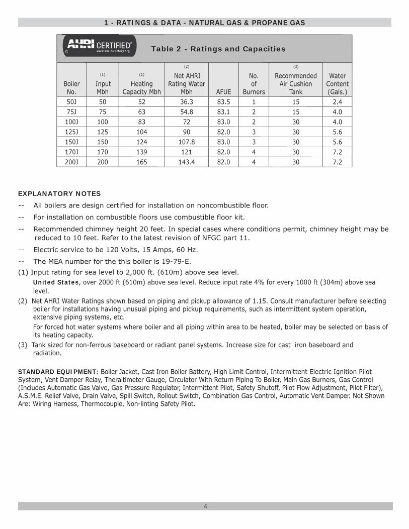
Table 2 - Ratings and Capacities
BoilerNo.
(1)
Input Mbh
(1)
Heating Capacity Mbh
(2)
Net AHRI Rating Water
Mbh AFUE
No.of
Burners
(3)
RecommendedAir Cushion
Tank
WaterContent(Gals.)
50J 50 52 36.3 83.5 1 15 2.475J 75 63 54.8 83.1 2 15 4.0100J 100 83 72 83.0 2 30 4.0125J 125 104 90 82.0 3 30 5.6150J 150 124 107.8 83.0 3 30 5.6170J 170 139 121 82.0 4 30 7.2200J 200 165 143.4 82.0 4 30 7.2
EXPLANATORY NOTES
-- All boilers are design certifi ed for installation on noncombustible fl oor.
-- For installation on combustible fl oors use combustible fl oor kit.
-- Recommended chimney height 20 feet. In special cases where conditions permit, chimney height may be reduced to 10 feet. Refer to the latest revision of NFGC part 11.
-- Electric service to be 120 Volts, 15 Amps, 60 Hz.
-- The MEA number for the this boiler is 19-79-E.(1) Input rating for sea level to 2,000 ft. (610m) above sea level.
United States, over 2000 ft (610m) above sea level. Reduce input rate 4% for every 1000 ft (304m) above sea level.
(2) Net AHRI Water Ratings shown based on piping and pickup allowance of 1.15. Consult manufacturer before selecting boiler for installations having unusual piping and pickup requirements, such as intermittent system operation, extensive piping systems, etc.For forced hot water systems where boiler and all piping within area to be heated, boiler may be selected on basis of its heating capacity.
(3) Tank sized for non-ferrous baseboard or radiant panel systems. Increase size for cast iron baseboard and radiation.
STANDARD EQUIPMENT: Boiler Jacket, Cast Iron Boiler Battery, High Limit Control, Intermittent Electric Ignition Pilot System, Vent Damper Relay, Theraltimeter Gauge, Circulator With Return Piping To Boiler, Main Gas Burners, Gas Control (Includes Automatic Gas Valve, Gas Pressure Regulator, Intermittent Pilot, Safety Shutoff, Pilot Flow Adjustment, Pilot Filter), A.S.M.E. Relief Valve, Drain Valve, Spill Switch, Rollout Switch, Combination Gas Control, Automatic Vent Damper. Not Shown Are: Wiring Harness, Thermocouple, Non-linting Safety Pilot.
1 - RATINGS & DATA - NATURAL GAS & PROPANE GAS
5
1. Installation must conform to the requirements of the authority having jurisdiction or, in the absence of such requirements, to the National Fuel Gas Code, ANSI Z223.1/NFPA 54.
2. Where required by the authority having jurisdiction, the installation must conform to the Standard for Controls and Safety Devices for Automatically fi red Boilers, ANSI/ASME CSD-1.
3. Boiler series is classifi ed as a Category I. Vent installation shall be in accordance with "Venting of Equipment ," of the National Fuel Gas Code, ANSI Z223.1/NFPA 54 or applicable provisions of the local building codes.
4. Boiler has met safe lighting and other performance criteria with the gas manifold and control assembly on the boiler per the latest revision of ANSI Z21.13/CGA 4.9.
5. Install boiler such that gas ignition system components are protected from water (dripping, spraying, rain, etc.) during appliance operation and service, (circulator replacement, condensate trap, control replacement, etc.).
6. Locate boiler on level, solid base as near chimney as possible and centrally located with respect to heat distribution system as practical.
7. Allow 24 inches (610mm ) at front and right side for servicing and cleaning.
8. When installed in utility room, door should be wide enough to allow largest boiler part to enter, or to permit replacement of another appliance such as water heater.
WARNINGFire hazard. Do not install boiler on combustible fl ooring or carpeting. Failure to follow these instructions could result in death or serious injury.
!
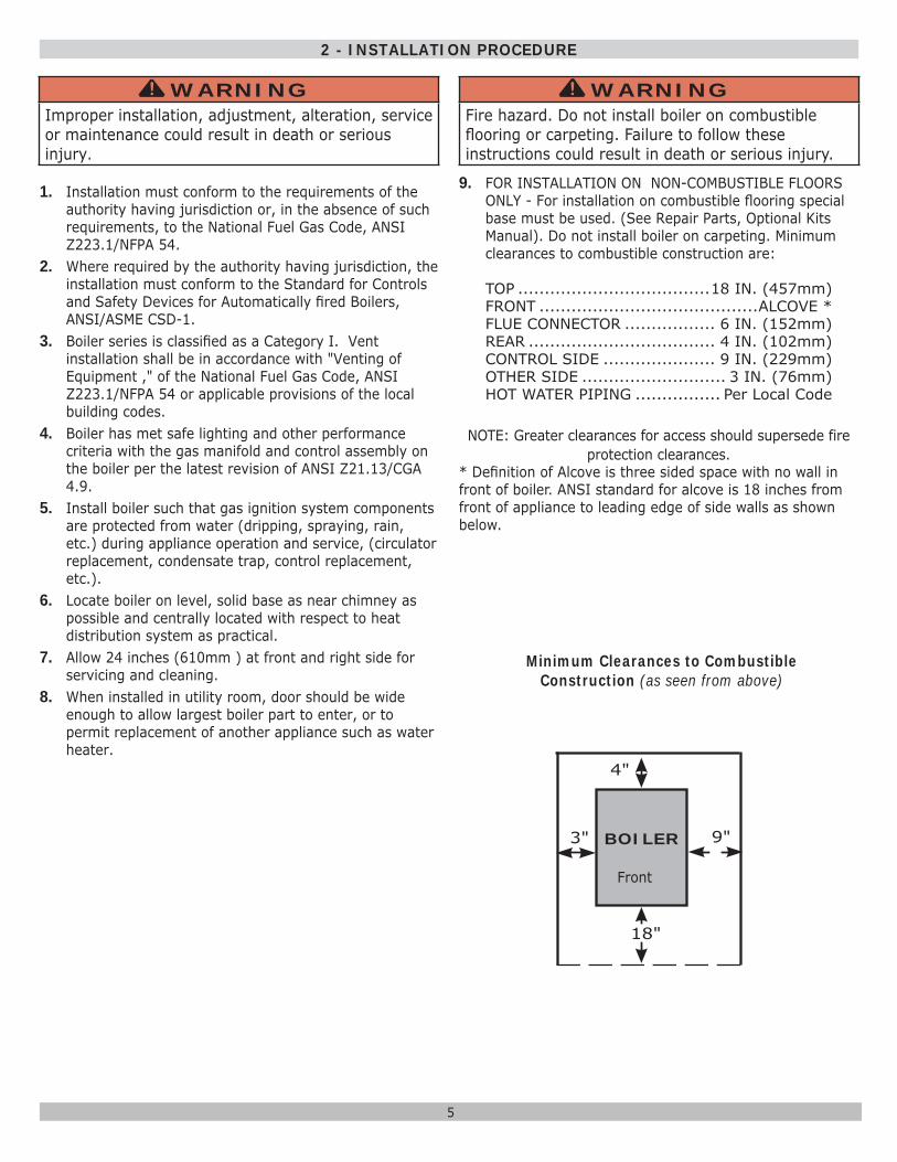
9. FOR INSTALLATION ON NON-COMBUSTIBLE FLOORS ONLY - For installation on combustible fl ooring special base must be used. (See Repair Parts, Optional Kits Manual). Do not install boiler on carpeting. Minimum clearances to combustible construction are:
TOP ....................................18 IN. (457mm)FRONT .........................................ALCOVE *FLUE CONNECTOR ................. 6 IN. (152mm)REAR ................................... 4 IN. (102mm)CONTROL SIDE ..................... 9 IN. (229mm)OTHER SIDE ........................... 3 IN. (76mm)HOT WATER PIPING ................ Per Local Code
NOTE: Greater clearances for access should supersede fire protection clearances.
* Defi nition of Alcove is three sided space with no wall in front of boiler. ANSI standard for alcove is 18 inches from front of appliance to leading edge of side walls as shown below.
Minimum Clearances to Combustible Construction (as seen from above)
3"
4"
BOILER
18"
9"
2 - INSTALLATION PROCEDURE
WARNINGImproper installation, adjustment, alteration, service or maintenance could result in death or serious injury.
!
Front
6
3 - VENTILATION & COMBUSTION AIR
Provide combustion air and ventilation air in accordance with the section “Air for Combustion and Ventilation,” of the National Fuel Gas Code, ANSI Z223.1/NFPA 54 or applicable provisions of local building codes.
Provide make-up air where exhaust fans, clothes dryers, and kitchen ventilation equipment interfere with proper operation.
National Fuel Gas Code recognizes several methods of obtaining adequate ventilation and combustion air. Requirements of the authority having jurisdiction may override these methods.
• Engineered Installations. Must be approved by authority having jurisdictions.
• Mechanical Air Supply. Provide minimum of 0.35 cfm per Mbh for all appliances located within space. Additional requirements where exhaust fans installed. Interlock each appliance to mechanical air supply system to prevent main burner operation when mechanical air supply system not operating.
• All Indoor Air. Calculate minimum volume for all appliances in space. Use a different method if minimum volume not available.
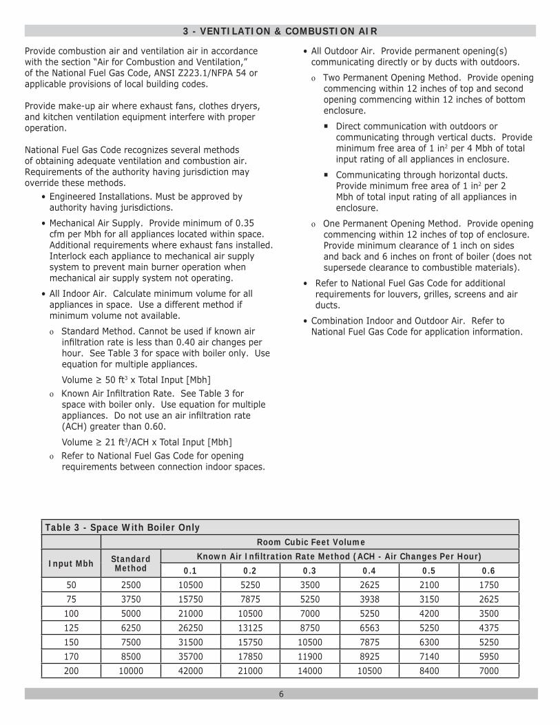
о Standard Method. Cannot be used if known air infi ltration rate is less than 0.40 air changes per hour. See Table 3 for space with boiler only. Use equation for multiple appliances.
Volume ≥ 50 ft3 x Total Input [Mbh] о Known Air Infi ltration Rate. See Table 3 for
space with boiler only. Use equation for multiple appliances. Do not use an air infi ltration rate (ACH) greater than 0.60.
Volume ≥ 21 ft3/ACH x Total Input [Mbh] о Refer to National Fuel Gas Code for opening
requirements between connection indoor spaces.
• All Outdoor Air. Provide permanent opening(s) communicating directly or by ducts with outdoors.
о Two Permanent Opening Method. Provide opening commencing within 12 inches of top and second opening commencing within 12 inches of bottom enclosure.
Direct communication with outdoors or communicating through vertical ducts. Provide minimum free area of 1 in2 per 4 Mbh of total input rating of all appliances in enclosure.
Communicating through horizontal ducts. Provide minimum free area of 1 in2 per 2 Mbh of total input rating of all appliances in enclosure.
о One Permanent Opening Method. Provide opening commencing within 12 inches of top of enclosure. Provide minimum clearance of 1 inch on sides and back and 6 inches on front of boiler (does not supersede clearance to combustible materials).
• Refer to National Fuel Gas Code for additional requirements for louvers, grilles, screens and air ducts.
• Combination Indoor and Outdoor Air. Refer to National Fuel Gas Code for application information.
Table 3 - Space With Boiler Only Room Cubic Feet Volume
Input Mbh Standard Method
Known Air Infi ltration Rate Method (ACH - Air Changes Per Hour)0.1 0.2 0.3 0.4 0.5 0.6
50 2500 10500 5250 3500 2625 2100 175075 3750 15750 7875 5250 3938 3150 2625100 5000 21000 10500 7000 5250 4200 3500125 6250 26250 13125 8750 6563 5250 4375150 7500 31500 15750 10500 7875 6300 5250170 8500 35700 17850 11900 8925 7140 5950200 10000 42000 21000 14000 10500 8400 7000
7
4 - CONNECTING SUPPLY AND RETURN PIPING
Check local codes for maximum distance
from fl oor or allowable safe point of discharge.
RELIEF VALVE
DISCHARGE LINE
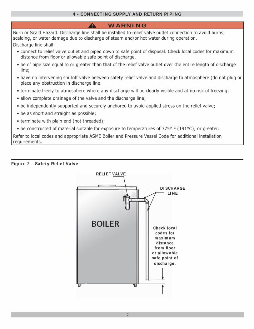
WARNINGBurn or Scald Hazard. Discharge line shall be installed to relief valve outlet connection to avoid burns, scalding, or water damage due to discharge of steam and/or hot water during operation.Discharge line shall:
• connect to relief valve outlet and piped down to safe point of disposal. Check local codes for maximum distance from fl oor or allowable safe point of discharge.
• be of pipe size equal to or greater than that of the relief valve outlet over the entire length of discharge line;
• have no intervening shutoff valve between safety relief valve and discharge to atmosphere (do not plug or place any obstruction in discharge line.
• terminate freely to atmosphere where any discharge will be clearly visible and at no risk of freezing;• allow complete drainage of the valve and the discharge line;• be independently supported and securely anchored to avoid applied stress on the relief valve;• be as short and straight as possible;• terminate with plain end (not threaded);• be constructed of material suitable for exposure to temperatures of 375° F (191°C); or greater.
Refer to local codes and appropriate ASME Boiler and Pressure Vessel Code for additional installation requirements.
!
Figure 2 - Safety Relief Valve
8
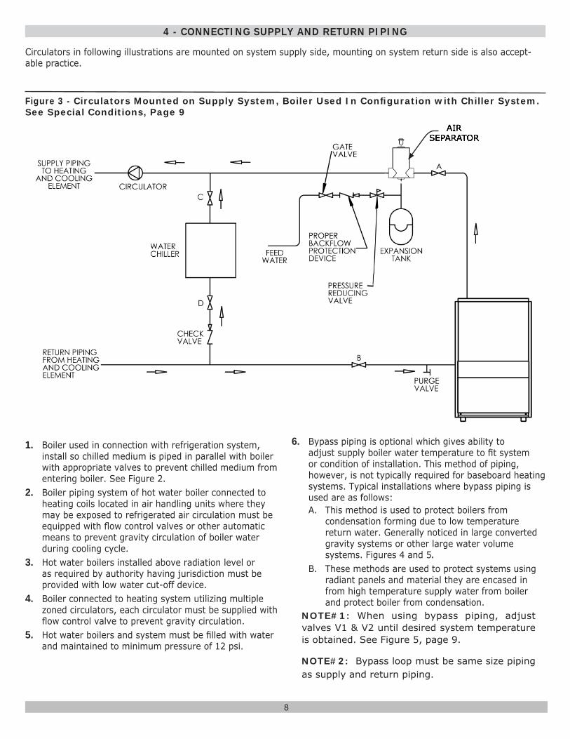
Circulators in following illustrations are mounted on system supply side, mounting on system return side is also accept-able practice.
1. Boiler used in connection with refrigeration system, install so chilled medium is piped in parallel with boiler with appropriate valves to prevent chilled medium from entering boiler. See Figure 2.
2. Boiler piping system of hot water boiler connected to heating coils located in air handling units where they may be exposed to refrigerated air circulation must be equipped with fl ow control valves or other automatic means to prevent gravity circulation of boiler water during cooling cycle.
3. Hot water boilers installed above radiation level or as required by authority having jurisdiction must be provided with low water cut-off device.
4. Boiler connected to heating system utilizing multiple zoned circulators, each circulator must be supplied with fl ow control valve to prevent gravity circulation.
5. Hot water boilers and system must be fi lled with water and maintained to minimum pressure of 12 psi.
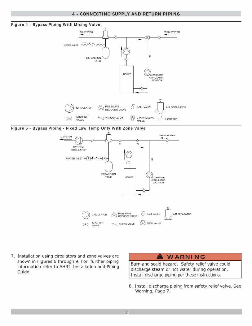
6. Bypass piping is optional which gives ability to adjust supply boiler water temperature to fi t system or condition of installation. This method of piping, however, is not typically required for baseboard heating systems. Typical installations where bypass piping is used are as follows:A. This method is used to protect boilers from
condensation forming due to low temperature return water. Generally noticed in large converted gravity systems or other large water volume systems. Figures 4 and 5.
B. These methods are used to protect systems using radiant panels and material they are encased in from high temperature supply water from boiler and protect boiler from condensation.
NOTE#1: When using bypass piping, adjust valves V1 & V2 until desired system temperature is obtained. See Figure 5, page 9.
NOTE#2: Bypass loop must be same size piping as supply and return piping.
4 - CONNECTING SUPPLY AND RETURN PIPING
Figure 3 - Circulators Mounted on Supply System, Boiler Used In Confi guration with Chiller System. See Special Conditions, Page 9
9
BOILER
WATER INLET
ALTERNATECIRCULATOR
LOCATION
TO SYSTEM FROM SYSTEM
CIRCULATOR
SHUT-OFFVALVE
PRESSUREREDUCER VALVE
CHECK VALVE
BALL VALVE
3 WAY MIXINGVALVE
AIR SEPARATOR
HOSE BIB
EXPANSIONTANK
7. Installation using circulators and zone valves are shown in Figures 6 through 9. For further piping information refer to AHRI Installation and Piping Guide.
WARNINGBurn and scald hazard. Safety relief valve could discharge steam or hot water during operation. Install discharge piping per these instructions.
!
8. Install discharge piping from safety relief valve. See Warning, Page 7.
4 - CONNECTING SUPPLY AND RETURN PIPING
BOILER ALTERNATECIRCULATOR
LOCATION
TO SYSTEM FROM SYSTEM
V2V1
CIRCULATOR
SHUT-OFFVALVE
PRESSUREREDUCER VALVE
CHECK VALVE
BALL VALVE AIR SEPARATOR
ZONE VALVE
EXPANSIONTANK
WATER INLET
SYSTEMCIRCULATOR
Figure 4 - Bypass Piping With Mixing Valve
Figure 5 - Bypass Piping - Fixed Low Temp Only With Zone Valve
10
4 - CONNECTING SUPPLY AND RETURN PIPING
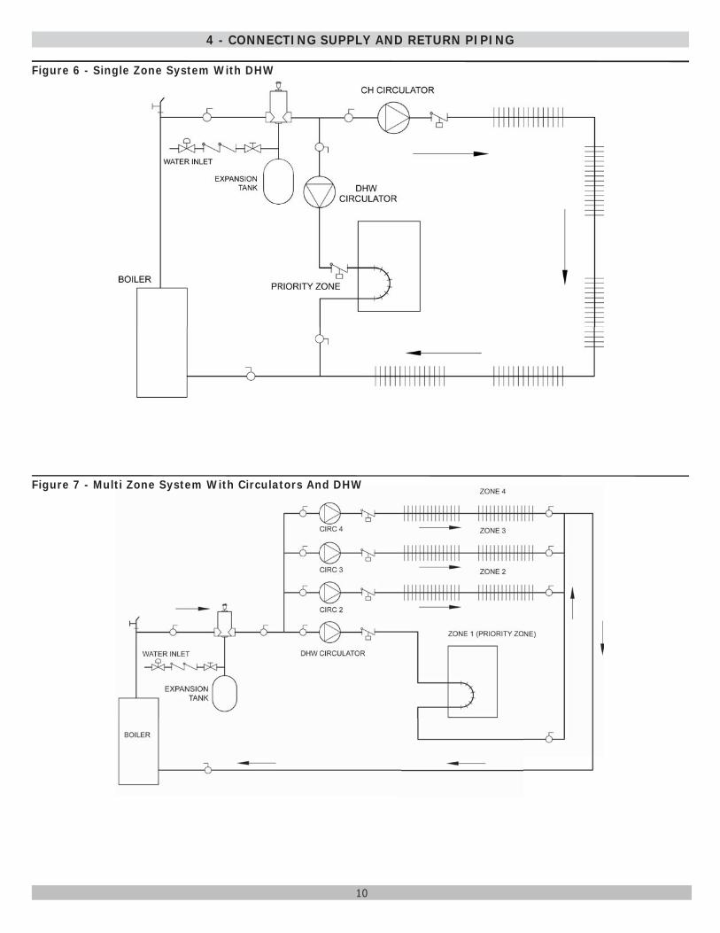
Figure 6 - Single Zone System With DHW
Figure 7 - Multi Zone System With Circulators And DHW
11
4 - CONNECTING SUPPLY AND RETURN PIPING
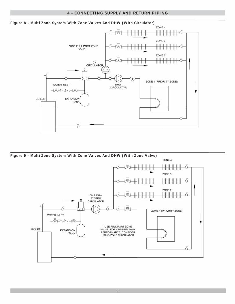
Figure 8 - Multi Zone System With Zone Valves And DHW (With Circulator)
Figure 9 - Multi Zone System With Zone Valves And DHW (With Zone Valve)
12
When an existing boiler is removed from a common venting system, the system is likely to be too large for the proper venting of the appliances sill connected to it. If this situation occurs, the following test procedure must be followed:
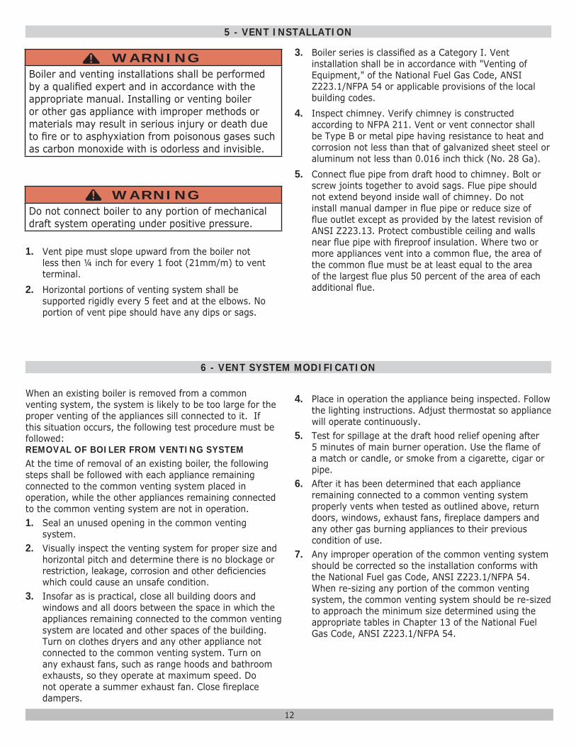
1. Vent pipe must slope upward from the boiler not less then ¼ inch for every 1 foot (21mm/m) to vent terminal.
2. Horizontal portions of venting system shall be supported rigidly every 5 feet and at the elbows. No portion of vent pipe should have any dips or sags.
3. Boiler series is classifi ed as a Category I. Vent installation shall be in accordance with "Venting of Equipment," of the National Fuel Gas Code, ANSI Z223.1/NFPA 54 or applicable provisions of the local building codes.
4. Inspect chimney. Verify chimney is constructed according to NFPA 211. Vent or vent connector shall be Type B or metal pipe having resistance to heat and corrosion not less than that of galvanized sheet steel or aluminum not less than 0.016 inch thick (No. 28 Ga).
5. Connect fl ue pipe from draft hood to chimney. Bolt or screw joints together to avoid sags. Flue pipe should not extend beyond inside wall of chimney. Do not install manual damper in fl ue pipe or reduce size of fl ue outlet except as provided by the latest revision of ANSI Z223.13. Protect combustible ceiling and walls near fl ue pipe with fi reproof insulation. Where two or more appliances vent into a common fl ue, the area of the common fl ue must be at least equal to the area of the largest fl ue plus 50 percent of the area of each additional fl ue.
5 - VENT INSTALLATION
6 - VENT SYSTEM MODIFICATION
REMOVAL OF BOILER FROM VENTING SYSTEMAt the time of removal of an existing boiler, the following steps shall be followed with each appliance remaining connected to the common venting system placed in operation, while the other appliances remaining connected to the common venting system are not in operation.1. Seal an unused opening in the common venting
system.2. Visually inspect the venting system for proper size and
horizontal pitch and determine there is no blockage or restriction, leakage, corrosion and other defi ciencies which could cause an unsafe condition.
3. Insofar as is practical, close all building doors and windows and all doors between the space in which the appliances remaining connected to the common venting system are located and other spaces of the building. Turn on clothes dryers and any other appliance not connected to the common venting system. Turn on any exhaust fans, such as range hoods and bathroom exhausts, so they operate at maximum speed. Do not operate a summer exhaust fan. Close fi replace dampers.
4. Place in operation the appliance being inspected. Follow the lighting instructions. Adjust thermostat so appliance will operate continuously.
5. Test for spillage at the draft hood relief opening after 5 minutes of main burner operation. Use the fl ame of a match or candle, or smoke from a cigarette, cigar or pipe.
6. After it has been determined that each appliance remaining connected to a common venting system properly vents when tested as outlined above, return doors, windows, exhaust fans, fi replace dampers and any other gas burning appliances to their previous condition of use.
7. Any improper operation of the common venting system should be corrected so the installation conforms with the National Fuel gas Code, ANSI Z223.1/NFPA 54. When re-sizing any portion of the common venting system, the common venting system should be re-sized to approach the minimum size determined using the appropriate tables in Chapter 13 of the National Fuel Gas Code, ANSI Z223.1/NFPA 54.
WARNINGBoiler and venting installations shall be performed by a qualifi ed expert and in accordance with the appropriate manual. Installing or venting boiler or other gas appliance with improper methods or materials may result in serious injury or death due to fi re or to asphyxiation from poisonous gases such as carbon monoxide with is odorless and invisible.
!
WARNINGDo not connect boiler to any portion of mechanical draft system operating under positive pressure.
!
13
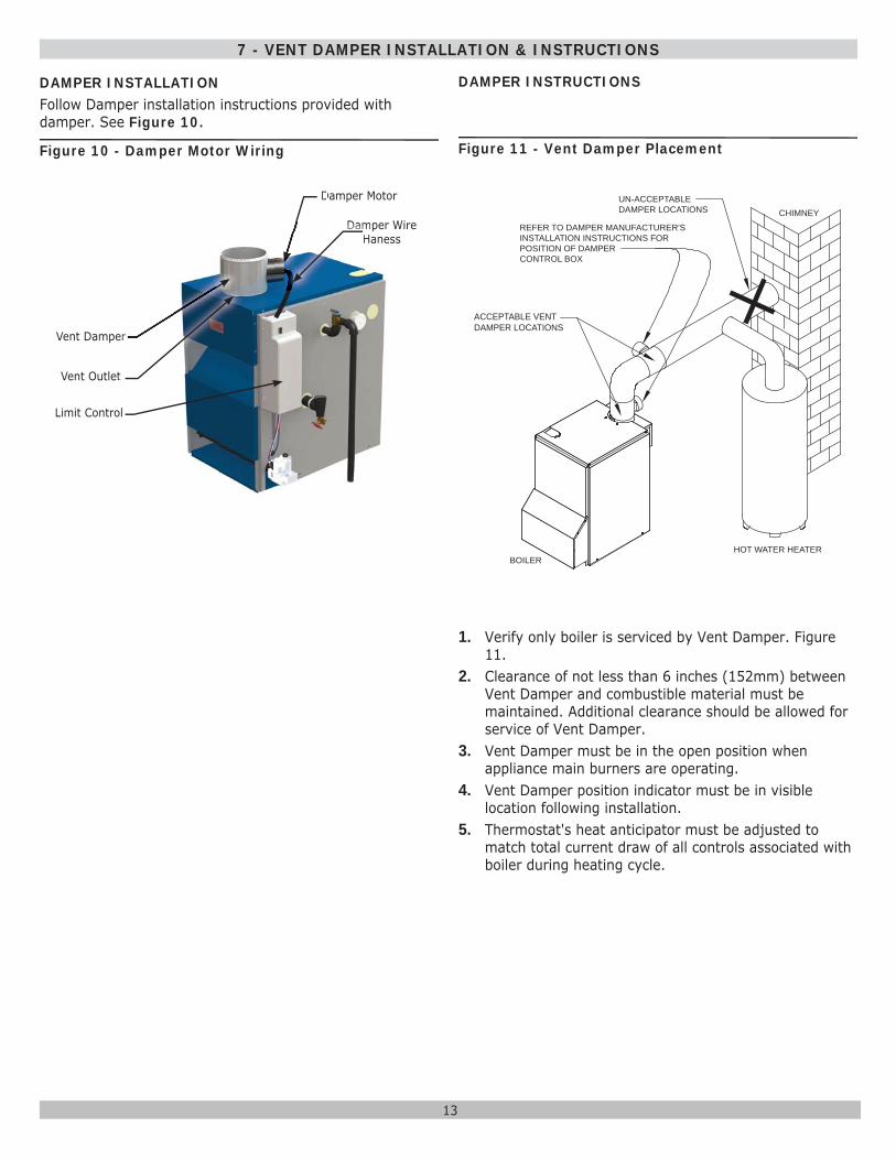
1. Verify only boiler is serviced by Vent Damper. Figure 11.
2. Clearance of not less than 6 inches (152mm) between Vent Damper and combustible material must be maintained. Additional clearance should be allowed for service of Vent Damper.
3. Vent Damper must be in the open position when appliance main burners are operating.
4. Vent Damper position indicator must be in visible location following installation.
5. Thermostat's heat anticipator must be adjusted to match total current draw of all controls associated with boiler during heating cycle.
7 - VENT DAMPER INSTALLATION & INSTRUCTIONS
Figure 10 - Damper Motor Wiring Figure 11 - Vent Damper Placement
DAMPER INSTALLATIONFollow Damper installation instructions provided with damper. See Figure 10.
Damper Motor
Vent Outlet
Vent Damper
DDDD
Damper Wire Haness
DamDamDamDamDamDamDamDaDaHHHHHaHa
etett
eeerrrrrr
Limit Control
REFER TO DAMPER MANUFACTURER'SINSTALLATION INSTRUCTIONS FORPOSITION OF DAMPERCONTROL BOX
ACCEPTABLE VENTDAMPER LOCATIONS
BOILERHOT WATER HEATER
CHIMNEYUN-ACCEPTABLEDAMPER LOCATIONS
DAMPER INSTRUCTIONS
14
8 - CONNECTING GAS SERVICE
General• Use piping materials and joining methods acceptable
to authority having jurisdiction. In absence of such requirements National Fuel gas Code, ANSI Z223.1/NFPA 54
• Size and install gas piping system to provide suffi cient gas supply to meet maximum input at not less than minimum supply pressure. See Table 4.
• Support piping with hooks straps, bands, brackets, hangers, or building structure components to prevent or dampen excessive vibrations and prevent strain on gas connection. Boiler will not support piping weight.
• Use thread (joint) compound (pipe dope) suitable for liquefi ed petroleum gas.
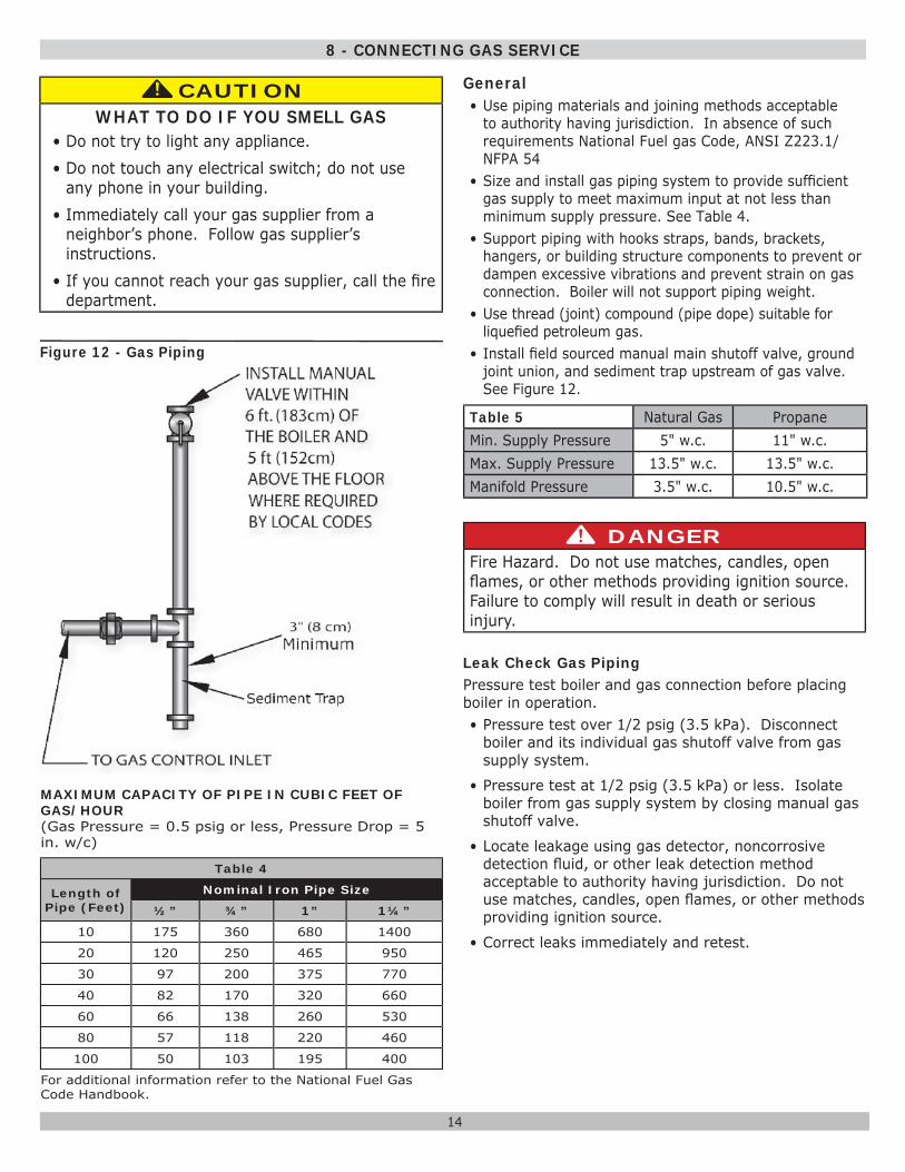
• Install fi eld sourced manual main shutoff valve, ground joint union, and sediment trap upstream of gas valve. See Figure 12.
Table 5 Natural Gas PropaneMin. Supply Pressure 5" w.c. 11" w.c.Max. Supply Pressure 13.5" w.c. 13.5" w.c.Manifold Pressure 3.5" w.c. 10.5" w.c.
DANGERFire Hazard. Do not use matches, candles, open fl ames, or other methods providing ignition source. Failure to comply will result in death or serious injury.
!
Leak Check Gas PipingPressure test boiler and gas connection before placing boiler in operation.• Pressure test over 1/2 psig (3.5 kPa). Disconnect
boiler and its individual gas shutoff valve from gas supply system.
• Pressure test at 1/2 psig (3.5 kPa) or less. Isolate boiler from gas supply system by closing manual gas shutoff valve.
• Locate leakage using gas detector, noncorrosive detection fl uid, or other leak detection method acceptable to authority having jurisdiction. Do not use matches, candles, open fl ames, or other methods providing ignition source.
• Correct leaks immediately and retest.
MAXIMUM CAPACITY OF PIPE IN CUBIC FEET OF GAS/HOUR(Gas Pressure = 0.5 psig or less, Pressure Drop = 5 in. w/c)
Table 4
Length of Pipe (Feet)
Nominal Iron Pipe Size
½” ¾” 1” 1¼”
10 175 360 680 1400
20 120 250 465 950
30 97 200 375 770
40 82 170 320 660
60 66 138 260 530
80 57 118 220 460
100 50 103 195 400
For additional information refer to the National Fuel Gas Code Handbook.
Figure 12 - Gas Piping
CAUTIONWHAT TO DO IF YOU SMELL GAS
• Do not try to light any appliance.• Do not touch any electrical switch; do not use
any phone in your building.• Immediately call your gas supplier from a
neighbor’s phone. Follow gas supplier’s instructions.
• If you cannot reach your gas supplier, call the fi re department.
!!
15
9 - ELECTRICAL SECTION
ELECTRICAL WIRINGSee wiring diagrams on the following two pages for details.Electrically bond boiler to ground in accordance with requirements of authority having jurisdiction. Refer to National Electrical Code, ANSI/NFPA 70.
THERMOSTAT INSTALLATION1. Thermostat should be installed on inside wall about
four feet above fl oor.2. NEVER install thermostat on outside wall. 3. Do not install thermostat where it will be affected by
drafts, hot or cold pipes, sunlight, lighting fi xtures, televisions, fi replace, or chimney.
4. Check thermostat operation by raising and lowering thermostat setting as required to start and stop burners.
5. Instructions for fi nal adjustment of thermostat are packaged with thermostat (adjusting heating anticipator, calibration, etc.)
WARNINGElectrical shock hazard. Turn OFF electrical power supply at service panel before making electrical connections. Failure to do so could result in death or serious injury.
!
16
10 - WIRING DIAGRAM
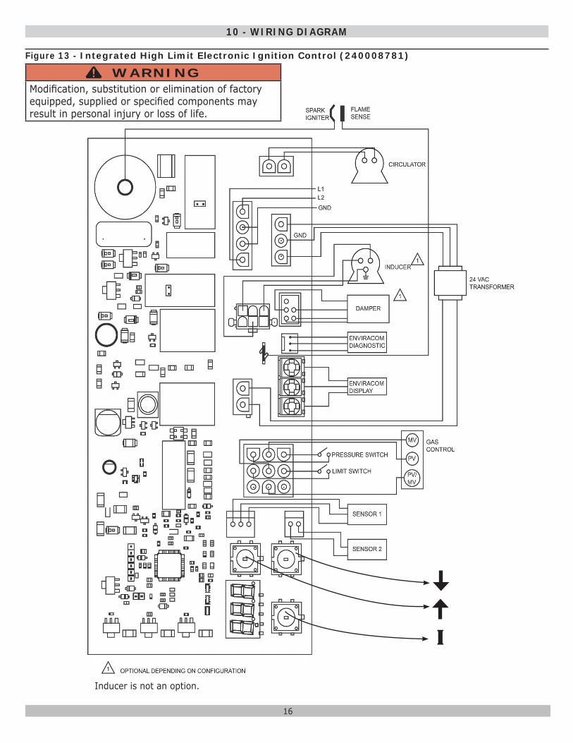
Figure 13 - Integrated High Limit Electronic Ignition Control (240008781)
I
Inducer is not an option.
WARNINGModifi cation, substitution or elimination of factory equipped, supplied or specifi ed components may result in personal injury or loss of life.
!
17
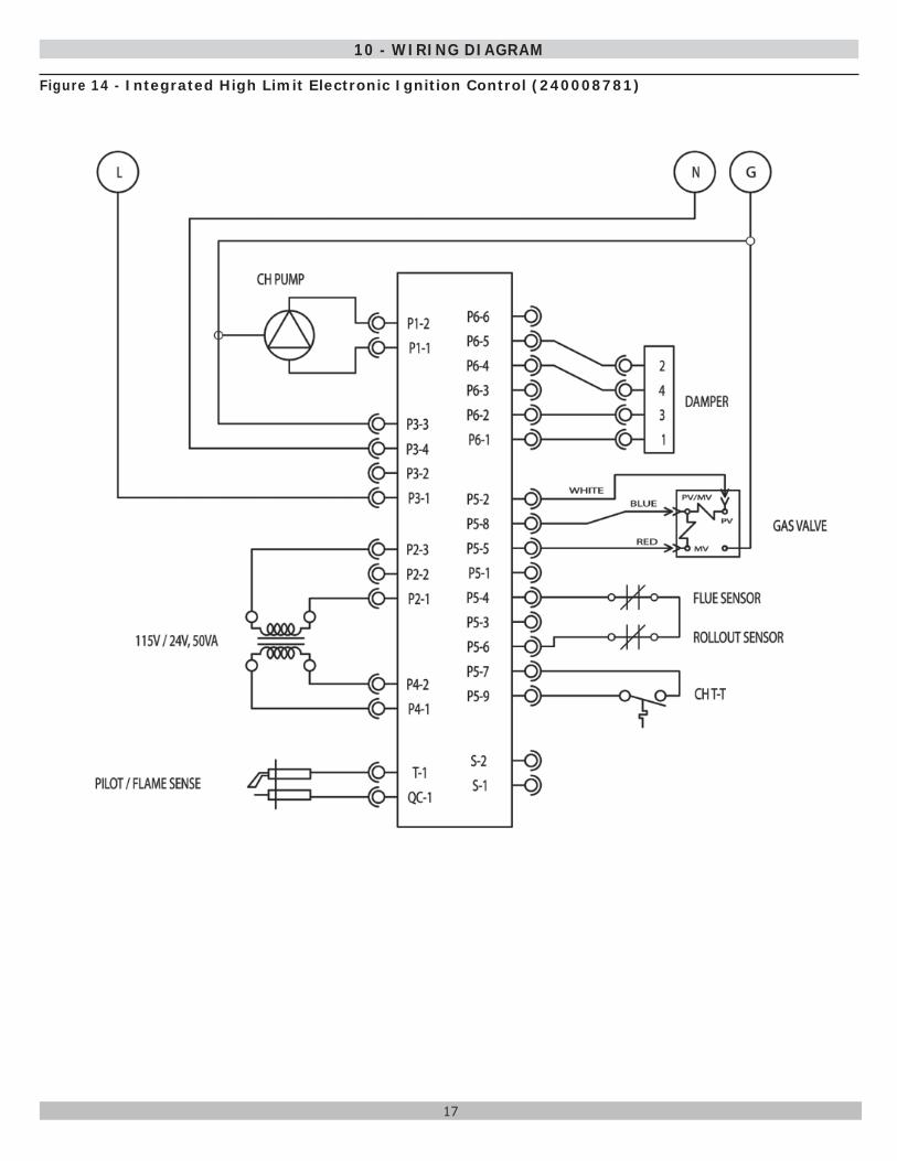
10 - WIRING DIAGRAM
Figure 14 - Integrated High Limit Electronic Ignition Control (240008781)
18
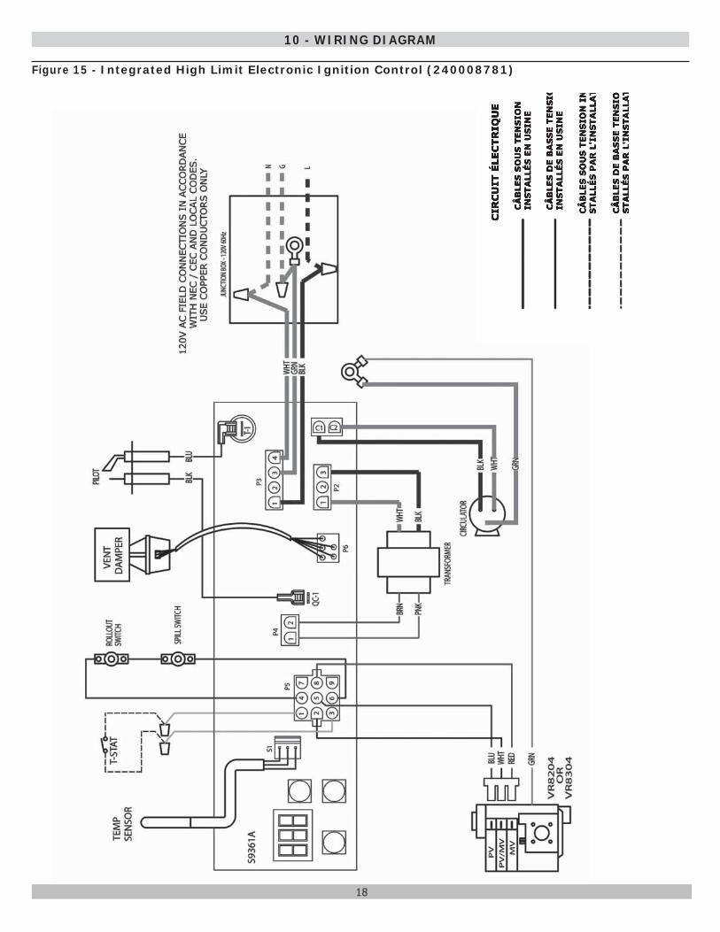
10 - WIRING DIAGRAM
Figure 15 - Integrated High Limit Electronic Ignition Control (240008781)
19
11 - LIGHTING INSTRUCTIONS
LIGHTING PROCEDURE FOR BOILER WITH INTERMITTENT PILOT SYSTEMA. This appliance is equipped with an ignition device which
automatically lights the pilot. Do not try to light the appliance by hand.
CAUTIONWHAT TO DO IF YOU SMELL GAS
• Do not try to light any appliance.
• Do not touch any electrical switches; do not use any phone in your building.
• Immediately call your gas supplier from a neighbor’s phone. Follow the gas supplier’s instructions.
• If you cannot reach your gas supplier, call the fi re department.
!!
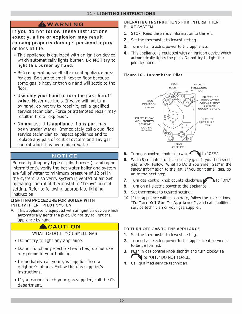
OPERATING INSTRUCTIONS FOR INTERMITTENT PILOT SYSTEM1. STOP! Read the safety information to the left.2. Set the thermostat to lowest setting.3. Turn off all electric power to the appliance.4. This appliance is equipped with an ignition device which
automatically lights the pilot. Do not try to light the pilot by hand.
Figure 16 - Intermittent Pilot
5. Turn gas control knob clockwise to “OFF.”6. Wait (5) minutes to clear out any gas. If you then smell
gas, STOP! Follow “What To Do If You Smell Gas” in the safety information to the left. If you don’t smell gas, go on to the next step.
7. Turn gas control knob counterclockwise to “ON.”8. Turn on all electric power to the appliance.9. Set thermostat to desired setting.10. If the appliance will not operate, follow the instructions
“To Turn Off Gas To Appliance” , and call qualifi ed service technician or your gas supplier.
TO TURN OFF GAS TO THE APPLIANCE1. Set the thermostat to lowest setting.2. Turn off all electric power to the appliance if service is
to be performed.3. Push in gas control knob slightly and turn clockwise
to "OFF." DO NOT FORCE.4. Call qualifi ed service technician.
WARNINGIf you do not follow these instructions exactly, a fi re or explosion may result causing property damage, personal injury or loss of life.• This appliance is equipped with an ignition device
which automatically lights burner. Do NOT try to light this burner by hand.
• Before operating smell all around appliance area for gas. Be sure to smell next to fl oor because some gas is heavier than air and will settle to the fl oor.
• Use only your hand to turn the gas shutoff valve. Never use tools. If valve will not turn by hand, do not try to repair it, call a qualifi ed service technician. Force or attempted repair may result in fi re or explosion.
• Do not use this appliance if any part has been under water. Immediately call a qualifi ed service technician to inspect appliance and to replace any part of control system and any gas control which has been under water.
!
NOTICEBefore lighting any type of pilot burner (standing or intermittent), verify the hot water boiler and system are full of water to minimum pressure of 12 psi in the system, also verify system is vented of air. Set operating control of thermostat to “below” normal setting. Refer to following appropriate lighting instruction.
20
12 - NORMAL SEQUENCE OF OPERATION
13 - GENERAL INSTRUCTIONS
Thermostat actuates on call for heat, completing circuit to control. Completed circuit to control will fi rst activate circulator and damper which will close end switch inside damper. Completes circuit to ignition system, ignition takes place.
In event boiler water temperature exceeds high limit setting on boiler mounted high limit control, power is interrupted between control system and ignition system. Power remains off until boiler water temperature drops below high limit setting. Circulator continues to operate under this condition until thermostat is satisfi ed.
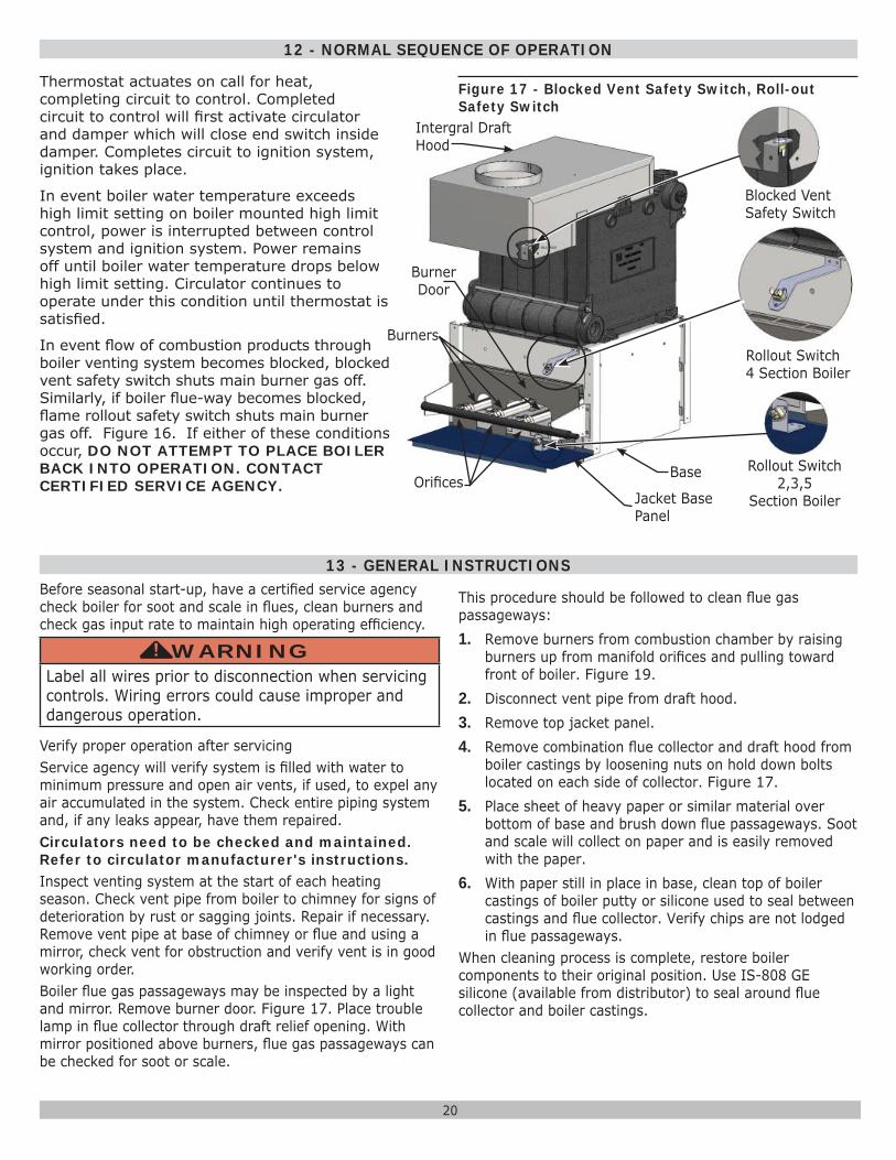
In event fl ow of combustion products through boiler venting system becomes blocked, blocked vent safety switch shuts main burner gas off. Similarly, if boiler fl ue-way becomes blocked, fl ame rollout safety switch shuts main burner gas off. Figure 16. If either of these conditions occur, DO NOT ATTEMPT TO PLACE BOILER BACK INTO OPERATION. CONTACT CERTIFIED SERVICE AGENCY.
Blocked Vent Safety Switch
Rollout Switch 4 Section Boiler
Rollout Switch 2,3,5
Section Boiler
Intergral Draft Hood
Base
Burner Door
Burners
Orifi cesJacket Base Panel
Before seasonal start-up, have a certifi ed service agency check boiler for soot and scale in fl ues, clean burners and check gas input rate to maintain high operating effi ciency.
WARNINGLabel all wires prior to disconnection when servicing controls. Wiring errors could cause improper and dangerous operation.
!
Verify proper operation after servicingService agency will verify system is fi lled with water to minimum pressure and open air vents, if used, to expel any air accumulated in the system. Check entire piping system and, if any leaks appear, have them repaired.Circulators need to be checked and maintained. Refer to circulator manufacturer's instructions.Inspect venting system at the start of each heating season. Check vent pipe from boiler to chimney for signs of deterioration by rust or sagging joints. Repair if necessary. Remove vent pipe at base of chimney or fl ue and using a mirror, check vent for obstruction and verify vent is in good working order.Boiler fl ue gas passageways may be inspected by a light and mirror. Remove burner door. Figure 17. Place trouble lamp in fl ue collector through draft relief opening. With mirror positioned above burners, fl ue gas passageways can be checked for soot or scale.
This procedure should be followed to clean fl ue gas passageways:1. Remove burners from combustion chamber by raising
burners up from manifold orifi ces and pulling toward front of boiler. Figure 19.
2. Disconnect vent pipe from draft hood.3. Remove top jacket panel.4. Remove combination fl ue collector and draft hood from
boiler castings by loosening nuts on hold down bolts located on each side of collector. Figure 17.
5. Place sheet of heavy paper or similar material over bottom of base and brush down fl ue passageways. Soot and scale will collect on paper and is easily removed with the paper.
6. With paper still in place in base, clean top of boiler castings of boiler putty or silicone used to seal between castings and fl ue collector. Verify chips are not lodged in fl ue passageways.
When cleaning process is complete, restore boiler components to their original position. Use IS-808 GE silicone (available from distributor) to seal around fl ue collector and boiler castings.
Figure 17 - Blocked Vent Safety Switch, Roll-out Safety Switch
21
13 - GENERAL INSTRUCTIONS
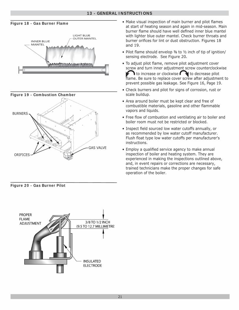
Figure 18 - Gas Burner Flame
Figure 20 - Gas Burner Pilot
Figure 19 - Combustion Chamber
BURNERS
ORIFICES
GAS VALVE
• Make visual inspection of main burner and pilot fl ames at start of heating season and again in mid-season. Main burner fl ame should have well defi ned inner blue mantel with lighter blue outer mantel. Check burner throats and burner orifi ces for lint or dust obstruction. Figures 18 and 19.
• Pilot fl ame should envelop ⅜ to ½ inch of tip of ignition/sensing electrode. See Figure 20.
• To adjust pilot fl ame, remove pilot adjustment cover screw and turn inner adjustment screw counterclockwise
to increase or clockwise to decrease pilot fl ame. Be sure to replace cover screw after adjustment to prevent possible gas leakage. See Figure 16, Page 19.
• Check burners and pilot for signs of corrosion, rust or scale buildup.
• Area around boiler must be kept clear and free of combustible materials, gasoline and other fl ammable vapors and liquids.
• Free fl ow of combustion and ventilating air to boiler and boiler room must not be restricted or blocked.
• Inspect fi eld sourced low water cutoffs annually, or as recommended by low water cutoff manufacturer. Flush fl oat type low water cutoffs per manufacturer's instructions.
• Employ a qualifi ed service agency to make annual inspection of boiler and heating system. They are experienced in making the inspections outlined above, and, in event repairs or corrections are necessary, trained technicians make the proper changes for safe operation of the boiler.
22
• Adjust gas input to boiler by removing protective cap on pressure regulator, and turning screw clockwise to increase input and counterclockwise to decrease input.
• Manifold pressures are taken at outlet side of gas valve.
• To check for proper fl ow of natural gas to boiler, divide input rate shown on rating plate by heating value of gas obtained from local gas company. This determines number of cubic feet of gas required per hour.
• With all other gas appliances off, determine fl ow of gas through meter for two minutes and multiply by 30 to get hourly rate.
• Make minor adjustments to gas input as described above. See Figure 16 page 18.
• Change burner orifi ces if fi nal manifold pressure varies more than plus or minus 0.3 inches water column from specifi ed pressure listed on boiler rating plate.
• Primary air adjustment is not necessary, therefore air shutters are not furnished as standard equipment.
CHECK SAFETY CONTROL CIRCUIT. Test ignition system safety shutoff device after placing boiler in operation. Figure 15 page 19.1. Intermittent Pilot: With main burner operating, turn
pilot gas adjusting screw clockwise until pilot gas is turned off. Within 90 seconds main gas control closes, shutting off gas to main burner.
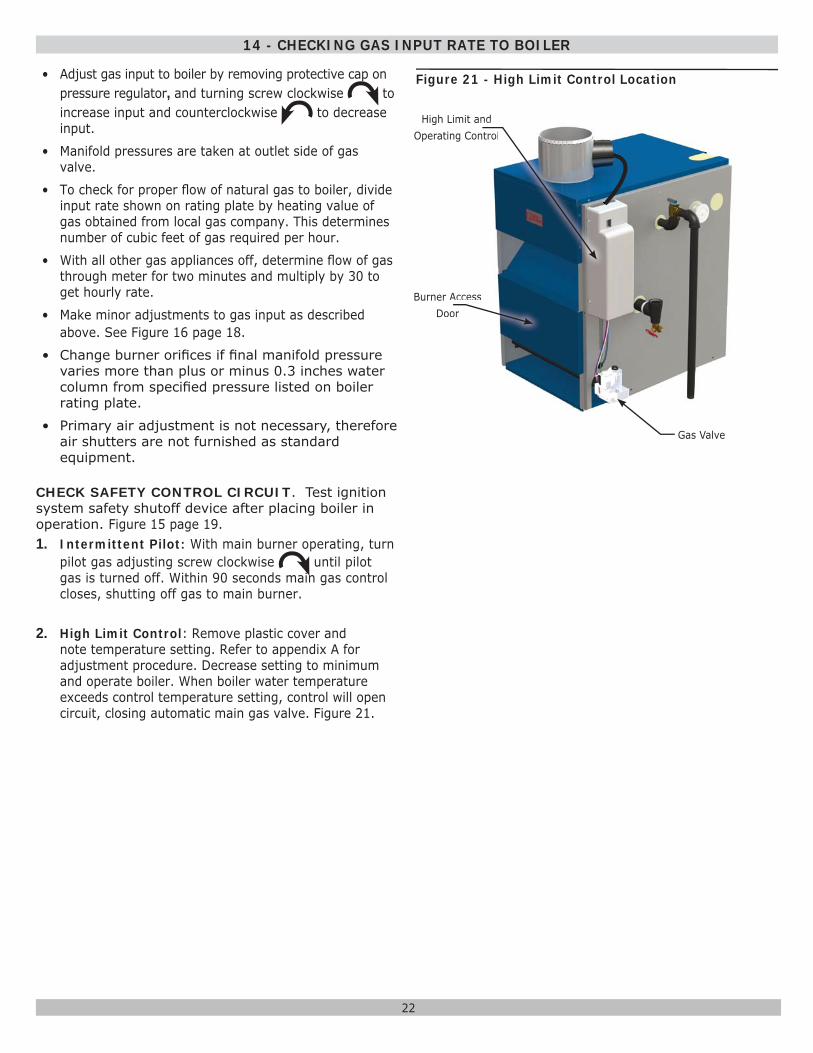
2. High Limit Control: Remove plastic cover and note temperature setting. Refer to appendix A for adjustment procedure. Decrease setting to minimum and operate boiler. When boiler water temperature exceeds control temperature setting, control will open circuit, closing automatic main gas valve. Figure 21.
14 - CHECKING GAS INPUT RATE TO BOILER
Figure 21 - High Limit Control Location
Burner Access Door
Gas Valve
High Limit and Operating Control
rr AAcAcAcAcAc escescescescece sssooooorrr
aannnnnndndndndoontntttnttttrtrtr lllolololol
23
APPENDIX A - CONTROL MODULE
A.1 Installation Environment Considerations
WARNINGIf you do not follow these instructions exactly, a fi re or explosion may result causing property damage, personal injury or loss of life.• Do not use this appliance if any part has
been under water. Immediately call a qualifi ed service technician to inspect appliance and to replace any part of control system and any gas control which has been under water.
• Do not allow water to drip on controls. Prevent condensation by allowing air circulation around module and gas control.
• Do not use corrosive chemicals around or on module or gas control.
!
• Controls can be damaged by excessively high temperatures. Verify adequate air circulation around control is maintained when installing boiler.
A.2 Electrical ConnectionsConnect Module Connectors Figure 13, Page 16
• Connect L1& L2 leads inside J-box using wire nuts. Secure J-box cover.
• Connect Circulator harness to circulator. Harness comes plugged into module with Molex® plug.
• Connect thermostat connection to yellow wires marked TT using wire nuts.
• Ensure remaining Molex® plug connectors have not worked loose during transit.
• Check sensing bulb is fully inserted in well and is not loose.
A.3 Adjusting SettingsTo discourage unauthorized changing of settings, procedure to enter adjustment mode is required. To enter adjustment mode, press UP, DOWN, and I buttons simultaneously for three seconds. Press and release I button until parameter requiring adjustment is displayed. See Figure 12, page 16.
о “SP_” Setpoint (180 °F default setting; adjustable between 130 and 220 °F)
о “Df_” Setpoint Differential (15 °F default setting; adjustable between 10 and 30 °F)
о “°F_” Degrees Fahrenheit
Press UP or DOWN button until parameter has reached desired value. After 60 seconds without any button inputs, control automatically returns to READ mode.
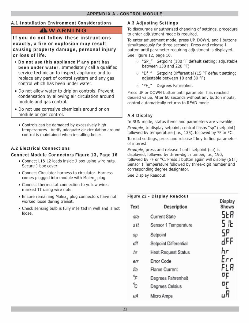
A.4 DisplayIn RUN mode, status items and parameters are viewable. Example, to display setpoint, control fl ashs “sp” (setpoint) followed by temperature (i.e., 135), followed by °F or °C.To read settings, press and release I key to fi nd parameter of interest. Example, press and release I until setpoint (sp) is displayed, followed by three-digit number, i.e., 190, followed by °F or °C. Press I button again will display (S1T) Sensor 1 Temperature followed by three-digit number and corresponding degree designator. See Display Readout.
Figure 22 - Display Readout
24
APPENDIX A - CONTROL MODULE
A.5 OperationModule continuously monitors boiler water temperature and fi res or shuts off burner based on this temperature data.1. When “Call for Heat” occurs, control enables circulator
and monitors boiler water temperature to determine whether thermostat can be satisfi ed without fi ring burners.
2. Control determines burner operation is required, module proceeds to start burner (see state codes list) and heats water in boiler until setpoint temperature is achieved or thermostat is satisfi ed. .
3. Burner is de-activated, ignition module completes heat-ing cycle, returns to idle and waits for temperature to drop again.
4. Circulator is turned on throughout “Call for Heat.”
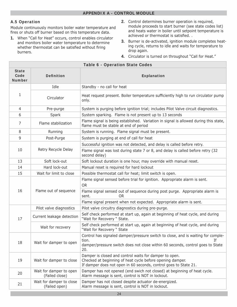
Table 6 - Operation State CodesState Code
NumberDefi nition Explanation
1
Idle Standby - no call for heat
Circulator Heat request present. Boiler temperature suffi ciently high to run circulator pump only.
4 Pre-purge System is purging before ignition trial; includes Pilot Valve circuit diagnostics.6 Spark System sparking. Flame is not present up to 13 seconds
7 Flame stabilization Flame signal is being established. Variation in signal is allowed during this state, fl ame must be stable at end of period
8 Running System is running. Flame signal must be present.9 Post-Purge System is purging at end of call for heat
10 Retry Recycle DelaySuccessful ignition was not detected, and delay is called before retry.Flame signal was lost during state 7 or 8, and delay is called before retry (32 second delay)
13 Soft lock-out Soft lockout duration is one hour, may override with manual reset.14 Hard lock-out Manual reset is required for hard lockout15 Wait for limit to close Possible thermostat call for heat; limit switch is open.
16 Flame out of sequence
Flame signal sensed before trial for ignition. Appropriate alarm is sent. ORFlame signal sensed out of sequence during post purge. Appropriate alarm is sent. ORFlame signal present when not expected. Appropriate alarm is sent.
17
Pilot valve diagnostics Pilot valve circuitry diagnostics during pre-purge.
Current leakage detection Self check performed at start up, again at beginning of heat cycle, and during “Wait for Recovery “ State.
Wait for recovery Self check performed at start up, again at beginning of heat cycle, and during “Wait for Recovery “ State
18 Wait for damper to open
Control has signaled damper/pressure switch to close, and is waiting for comple-tion. If damper/pressure switch does not close within 60 seconds, control goes to State 20.
19 Wait for damper to closeDamper is closed and control waits for damper to open. Checked at beginning of heat cycle before opening damper. If damper does not open in 60 seconds, control goes to State 21.
20 Wait for damper to open (Failed close)
Damper has not opened (end swich not closed) at beginning of heat cycle. Alarm message is sent, control is NOT in lockout.
21 Wait for damper to close (Failed open)
Damper has not closed despite actuator de-energized. Alarm message is sent, control is NOT in lockout.
25
APPENDIX A - CONTROL MODULE
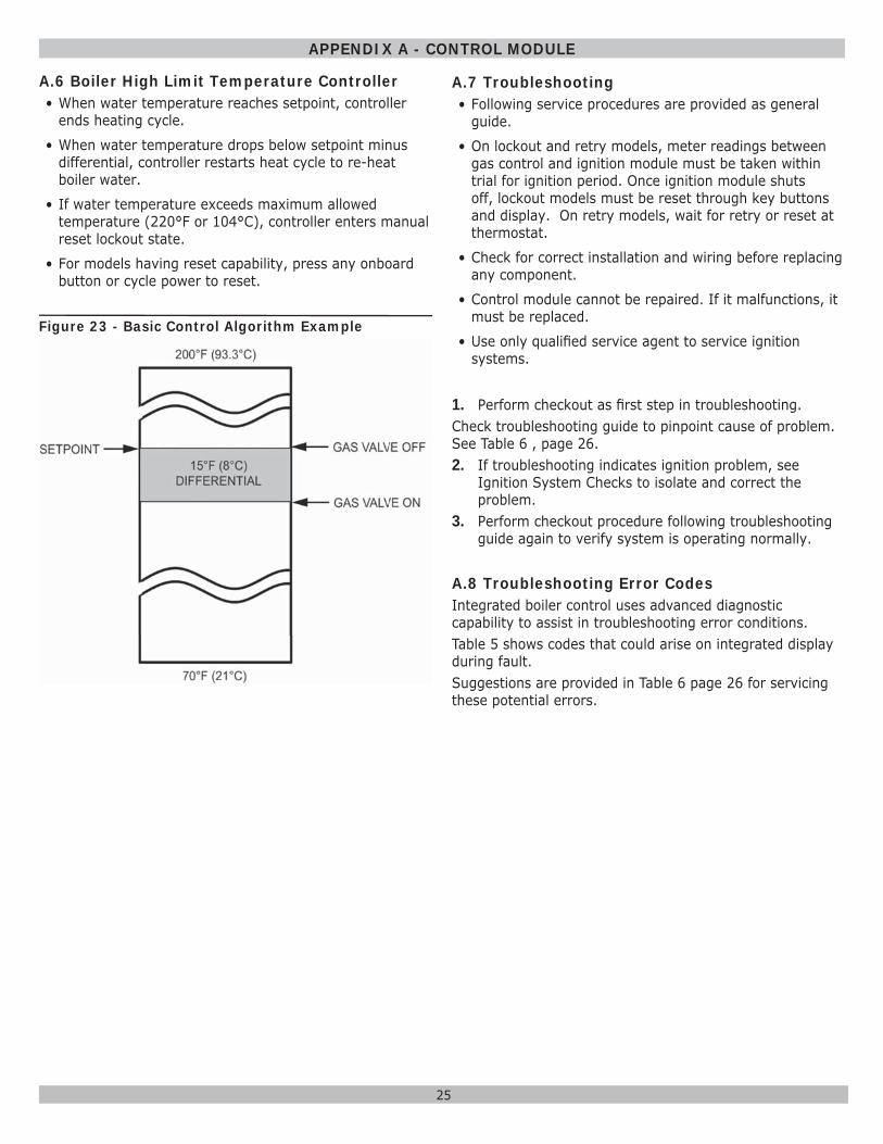
A.6 Boiler High Limit Temperature Controller• When water temperature reaches setpoint, controller
ends heating cycle.
• When water temperature drops below setpoint minus differential, controller restarts heat cycle to re-heat boiler water.
• If water temperature exceeds maximum allowed temperature (220°F or 104°C), controller enters manual reset lockout state.
• For models having reset capability, press any onboard button or cycle power to reset.
A.7 Troubleshooting• Following service procedures are provided as general
guide.
• On lockout and retry models, meter readings between gas control and ignition module must be taken within trial for ignition period. Once ignition module shuts off, lockout models must be reset through key buttons and display. On retry models, wait for retry or reset at thermostat.
• Check for correct installation and wiring before replacing any component.
• Control module cannot be repaired. If it malfunctions, it must be replaced.
• Use only qualifi ed service agent to service ignition systems.
1. Perform checkout as fi rst step in troubleshooting. Check troubleshooting guide to pinpoint cause of problem. See Table 6 , page 26.2. If troubleshooting indicates ignition problem, see
Ignition System Checks to isolate and correct the problem.
3. Perform checkout procedure following troubleshooting guide again to verify system is operating normally.
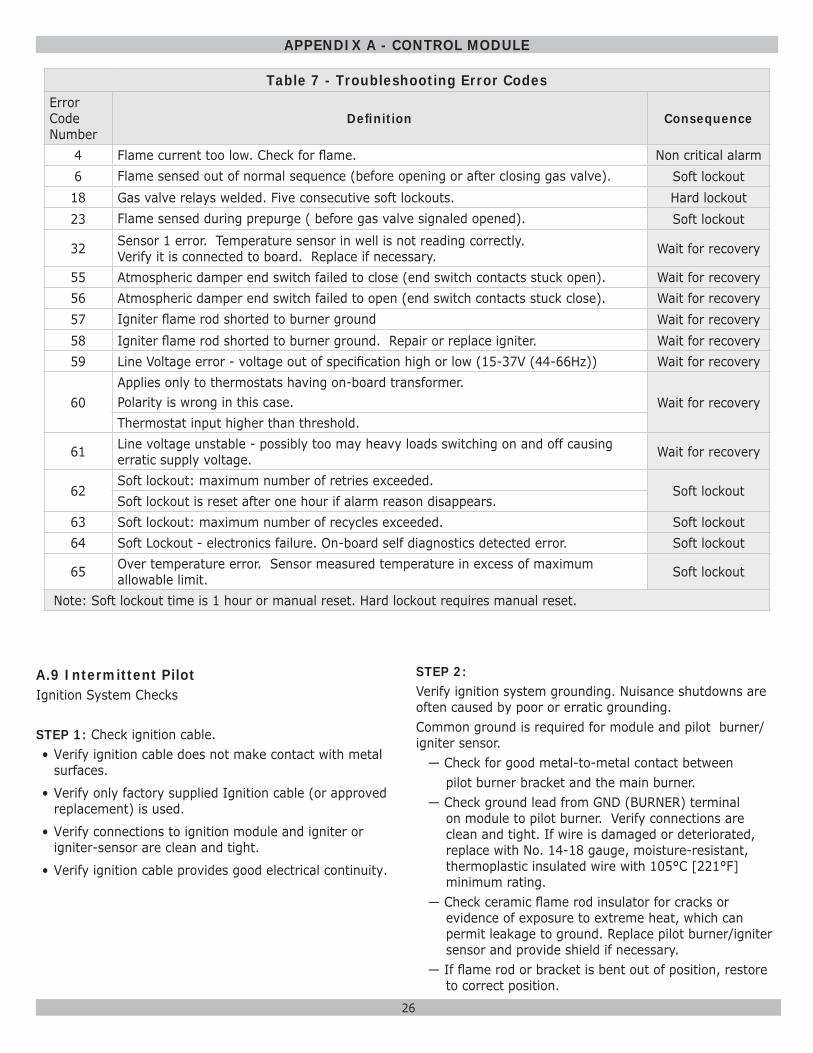
A.8 Troubleshooting Error CodesIntegrated boiler control uses advanced diagnostic capability to assist in troubleshooting error conditions. Table 5 shows codes that could arise on integrated display during fault. Suggestions are provided in Table 6 page 26 for servicing these potential errors.
Figure 23 - Basic Control Algorithm Example
26
APPENDIX A - CONTROL MODULE
Table 7 - Troubleshooting Error CodesError Code Number
Defi nition Consequence
4 Flame current too low. Check for fl ame. Non critical alarm6 Flame sensed out of normal sequence (before opening or after closing gas valve). Soft lockout18 Gas valve relays welded. Five consecutive soft lockouts. Hard lockout23 Flame sensed during prepurge ( before gas valve signaled opened). Soft lockout
32 Sensor 1 error. Temperature sensor in well is not reading correctly. Verify it is connected to board. Replace if necessary. Wait for recovery
55 Atmospheric damper end switch failed to close (end switch contacts stuck open). Wait for recovery56 Atmospheric damper end switch failed to open (end switch contacts stuck close). Wait for recovery57 Igniter fl ame rod shorted to burner ground Wait for recovery58 Igniter fl ame rod shorted to burner ground. Repair or replace igniter. Wait for recovery59 Line Voltage error - voltage out of specifi cation high or low (15-37V (44-66Hz)) Wait for recovery
60Applies only to thermostats having on-board transformer. Polarity is wrong in this case. Wait for recoveryThermostat input higher than threshold.
61 Line voltage unstable - possibly too may heavy loads switching on and off causing erratic supply voltage. Wait for recovery
62Soft lockout: maximum number of retries exceeded.
Soft lockoutSoft lockout is reset after one hour if alarm reason disappears.
63 Soft lockout: maximum number of recycles exceeded. Soft lockout64 Soft Lockout - electronics failure. On-board self diagnostics detected error. Soft lockout
65 Over temperature error. Sensor measured temperature in excess of maximum allowable limit. Soft lockout
Note: Soft lockout time is 1 hour or manual reset. Hard lockout requires manual reset.
A.9 Intermittent PilotIgnition System Checks
STEP 1: Check ignition cable.• Verify ignition cable does not make contact with metal
surfaces.
• Verify only factory supplied Ignition cable (or approved replacement) is used.
• Verify connections to ignition module and igniter or igniter-sensor are clean and tight.
• Verify ignition cable provides good electrical continuity.
STEP 2:Verify ignition system grounding. Nuisance shutdowns are often caused by poor or erratic grounding.Common ground is required for module and pilot burner/igniter sensor.
— Check for good metal-to-metal contact between pilot burner bracket and the main burner.— Check ground lead from GND (BURNER) terminal
on module to pilot burner. Verify connections are clean and tight. If wire is damaged or deteriorated, replace with No. 14-18 gauge, moisture-resistant, thermoplastic insulated wire with 105°C [221°F] minimum rating.
— Check ceramic fl ame rod insulator for cracks or evidence of exposure to extreme heat, which can permit leakage to ground. Replace pilot burner/igniter sensor and provide shield if necessary.
— If fl ame rod or bracket is bent out of position, restore to correct position.
27
APPENDIX A - CONTROL MODULE
STEP 3: Check spark ignition circuit. Disconnect ignition cable at SPARK terminal on module.
WARNINGElectrical shock hazard. Ignition circuit generates over 10,000 volts. Turn OFF electrical power supply at service panel before making electrical connections. Failure to do so could result in death or serious injury.
!
Energize module and listen for audible sparking noise. When operating normally, there should be a buzzing noise that turns on and off twice per second for duration of 1–7 seconds depending on model.STEP 4: Verify pilot and main burner lightoff.• Initiate call for heat. Turn thermostat above room
temperature. Ignition sequence may be delayed by thermal purge until boiler water temperature is below 140°F (60°C)
• Watch pilot burner during ignition sequence.
— Verify ignition spark continues after pilot is lit.— Verify pilot lights and spark stops, verify main
burner does not light.• If so, ensure adequate fl ame current as follows.
— Turn off boiler at circuit breaker or fuse box.— Clean fl ame rod with emery cloth.— Verify electrical connections are clean and tight.
Replace damaged wire..— Check for cracked ceramic insulator, which can
cause short to ground, and replace igniter-sensor if necessary.
— At gas valve, disconnect main valve wire from MV terminal.
— Turn on power and set thermostat to call for heat. Pilot should light, main burner will remain off because main valve actuator is disconnected.
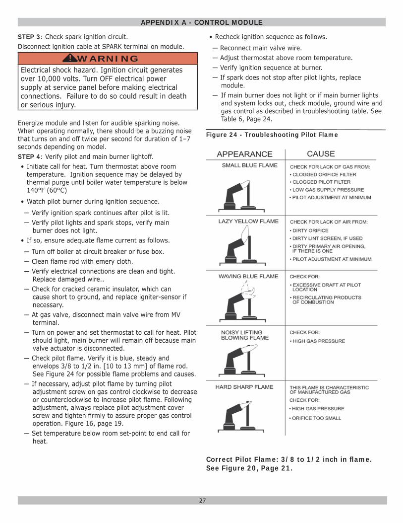
— Check pilot fl ame. Verify it is blue, steady and envelops 3/8 to 1/2 in. [10 to 13 mm] of fl ame rod. See Figure 24 for possible fl ame problems and causes.
— If necessary, adjust pilot fl ame by turning pilot adjustment screw on gas control clockwise to decrease or counterclockwise to increase pilot fl ame. Following adjustment, always replace pilot adjustment cover screw and tighten fi rmly to assure proper gas control operation. Figure 16, page 19.
— Set temperature below room set-point to end call for heat.
• Recheck ignition sequence as follows.
— Reconnect main valve wire.— Adjust thermostat above room temperature.— Verify ignition sequence at burner.— If spark does not stop after pilot lights, replace
module.— If main burner does not light or if main burner lights
and system locks out, check module, ground wire and gas control as described in troubleshooting table. See Table 6, Page 24.
Figure 24 - Troubleshooting Pilot Flame
Correct Pilot Flame: 3/8 to 1/2 inch in fl ame. See Figure 20, Page 21.

UTICA BOILERS2201 Dwyer Avenue
Utica NY 13501web site: www.ecrinternational.com