combustion & optimization in coal fired boilers
TRANSCRIPT
Combustion optimization in PF Boilers
Mr. K.Bhanu Prakash Date: XX.XX.2013
Topics layout
1. Coal and Combustion process
2. Boiler losses and efficiency
3. Combustion measurement and optimization
4. Online diagnostic optimization
5. Advance Optimization techniques
Date | Title of Presentation Page 2
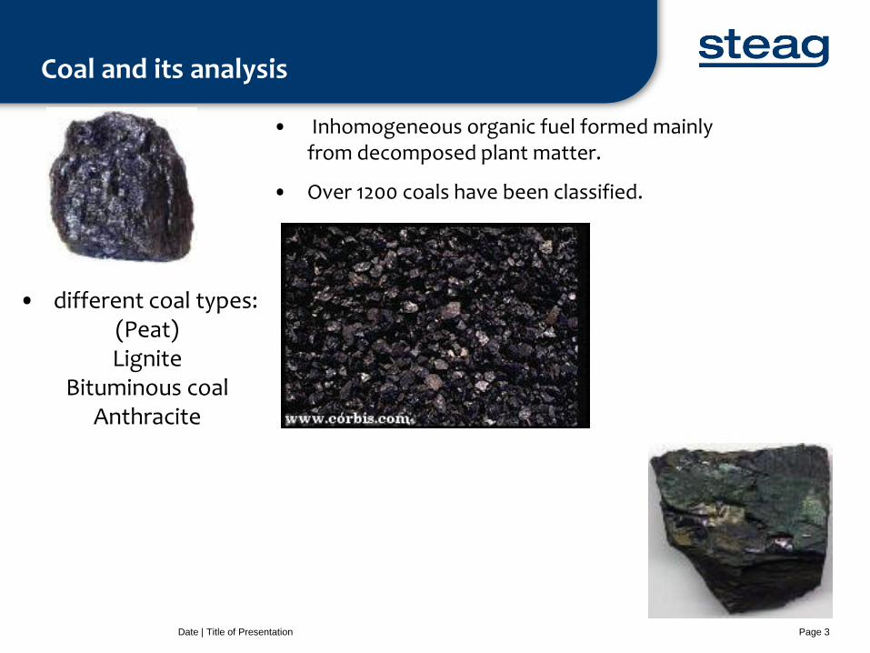
Coal and its analysis
Date | Title of Presentation Page 3
• Inhomogeneous organic fuel formed mainly from decomposed plant matter.
• Over 1200 coals have been classified.
• different coal types: (Peat) Lignite
Bituminous coal Anthracite
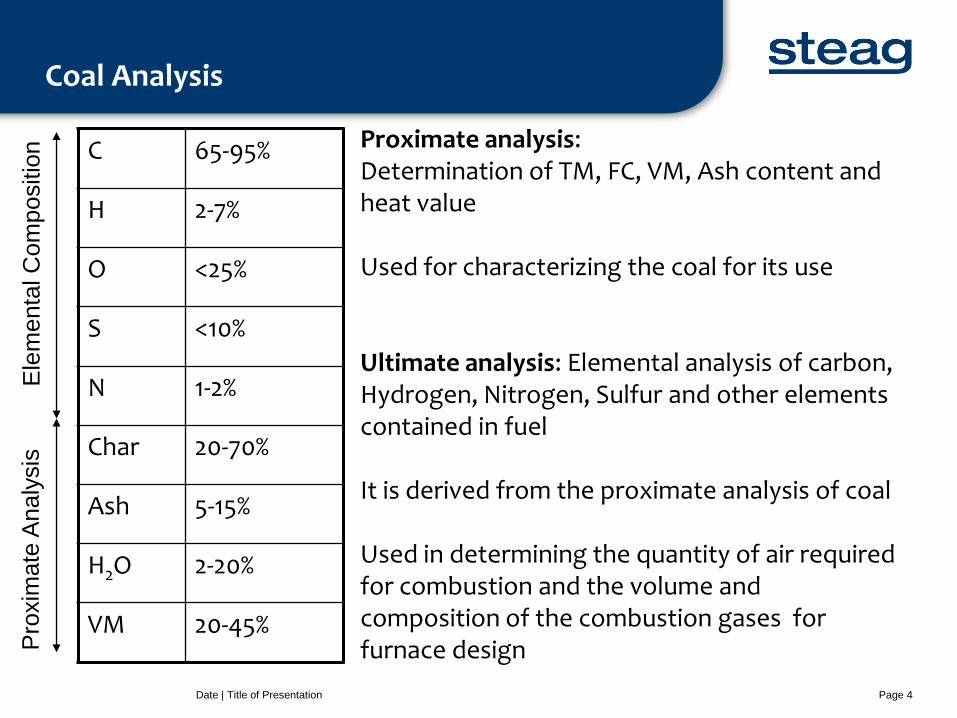
Coal Analysis
Date | Title of Presentation Page 4
65-95% C
2-7% H
<25% O
<10% S
1-2% N
20-70% Char
5-15% Ash
2-20% H2O
20-45% VM
Pro
xim
ate
Analy
sis
E
lem
enta
l C
om
positio
n Proximate analysis:
Determination of TM, FC, VM, Ash content and heat value Used for characterizing the coal for its use Ultimate analysis: Elemental analysis of carbon, Hydrogen, Nitrogen, Sulfur and other elements contained in fuel It is derived from the proximate analysis of coal Used in determining the quantity of air required for combustion and the volume and composition of the combustion gases for furnace design
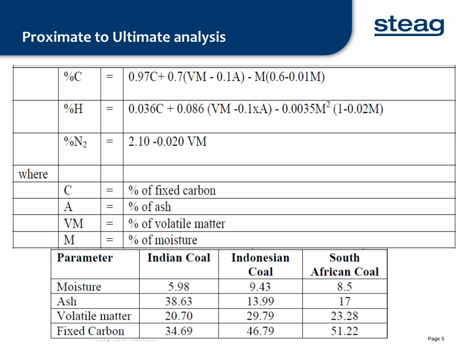
Proximate to Ultimate analysis
Date | Title of Presentation Page 5
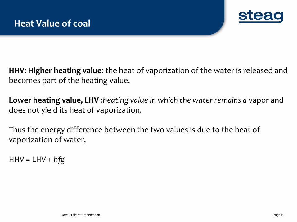
Heat Value of coal
Date | Title of Presentation Page 6
HHV: Higher heating value: the heat of vaporization of the water is released and becomes part of the heating value. Lower heating value, LHV :heating value in which the water remains a vapor and does not yield its heat of vaporization. Thus the energy difference between the two values is due to the heat of vaporization of water, HHV = LHV + hfg
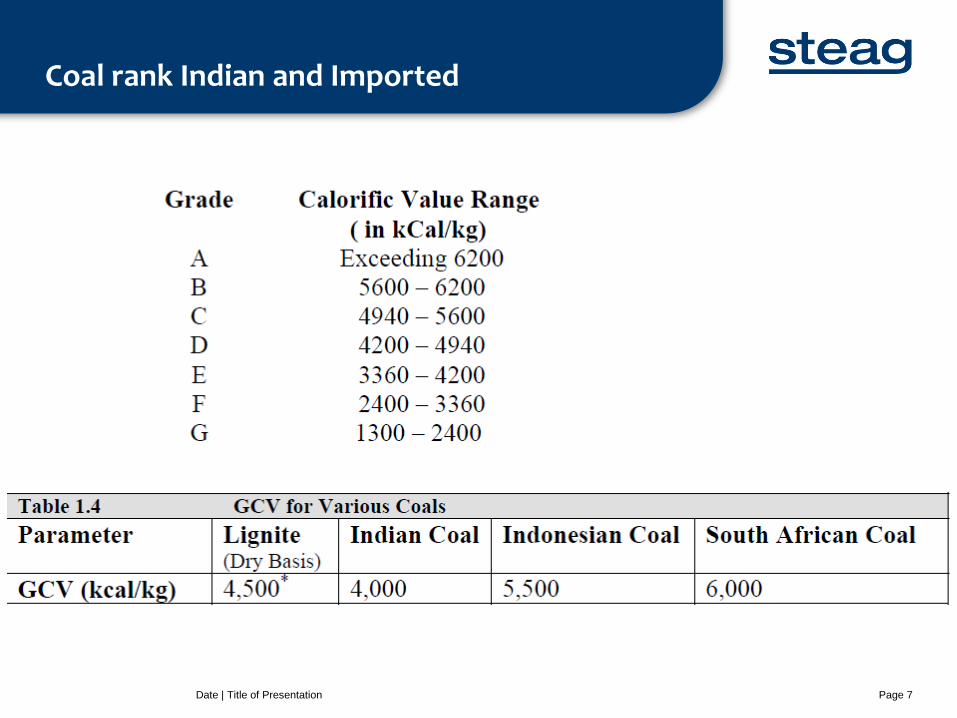
Coal rank Indian and Imported
Date | Title of Presentation Page 7
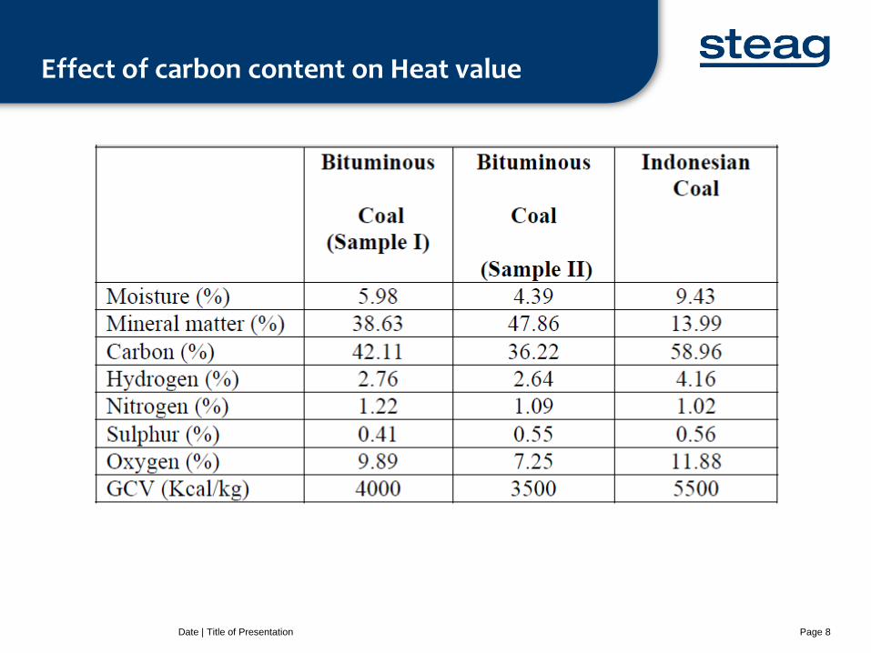
Effect of carbon content on Heat value
Date | Title of Presentation Page 8
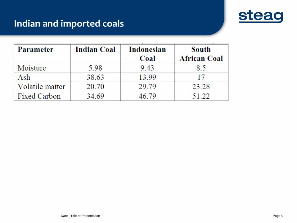
Indian and imported coals
Date | Title of Presentation Page 9
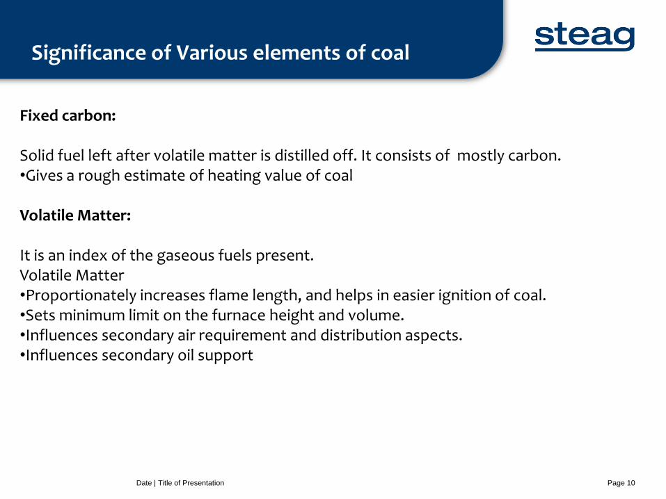
Significance of Various elements of coal
Date | Title of Presentation Page 10
Fixed carbon: Solid fuel left after volatile matter is distilled off. It consists of mostly carbon. •Gives a rough estimate of heating value of coal Volatile Matter: It is an index of the gaseous fuels present. Volatile Matter •Proportionately increases flame length, and helps in easier ignition of coal. •Sets minimum limit on the furnace height and volume. •Influences secondary air requirement and distribution aspects. •Influences secondary oil support
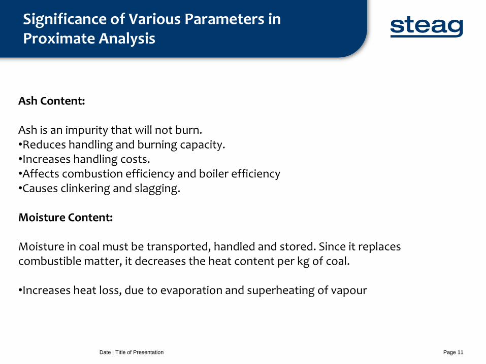
Significance of Various Parameters in Proximate Analysis
Date | Title of Presentation Page 11
Ash Content: Ash is an impurity that will not burn. •Reduces handling and burning capacity. •Increases handling costs. •Affects combustion efficiency and boiler efficiency •Causes clinkering and slagging. Moisture Content: Moisture in coal must be transported, handled and stored. Since it replaces combustible matter, it decreases the heat content per kg of coal. •Increases heat loss, due to evaporation and superheating of vapour
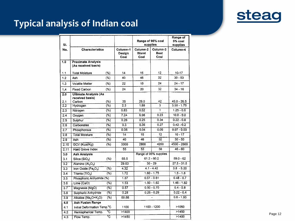
Typical analysis of Indian coal
Date | Title of Presentation Page 12
Boiler Losses and efficiency
Date | Title of Presentation Page 13
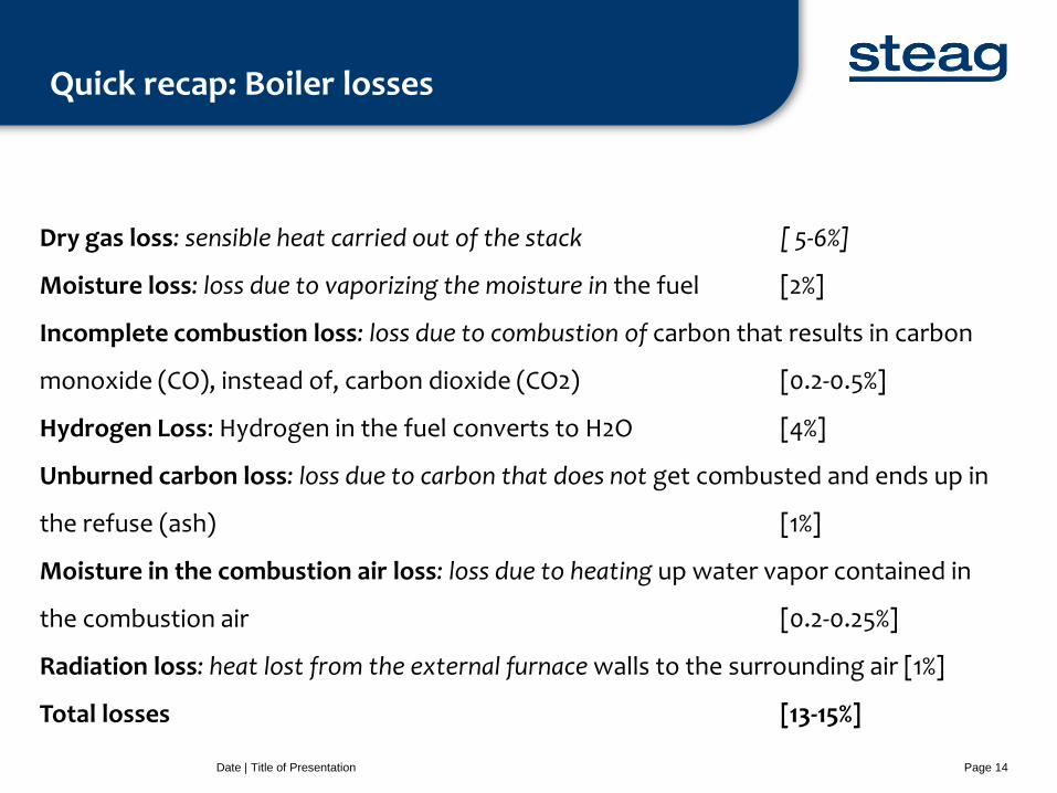
Quick recap: Boiler losses
Date | Title of Presentation Page 14
Dry gas loss: sensible heat carried out of the stack [ 5-6%]
Moisture loss: loss due to vaporizing the moisture in the fuel [2%]
Incomplete combustion loss: loss due to combustion of carbon that results in carbon
monoxide (CO), instead of, carbon dioxide (CO2) [0.2-0.5%]
Hydrogen Loss: Hydrogen in the fuel converts to H2O [4%]
Unburned carbon loss: loss due to carbon that does not get combusted and ends up in
the refuse (ash) [1%]
Moisture in the combustion air loss: loss due to heating up water vapor contained in
the combustion air [0.2-0.25%]
Radiation loss: heat lost from the external furnace walls to the surrounding air [1%]
Total losses [13-15%]
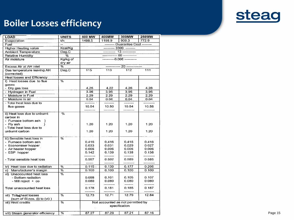
Boiler Losses efficiency
Date | Title of Presentation Page 15
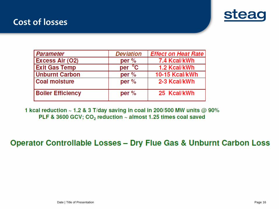
Cost of losses
Date | Title of Presentation Page 16
Combustion- a brief discussion
Date | Title of Presentation Page 17
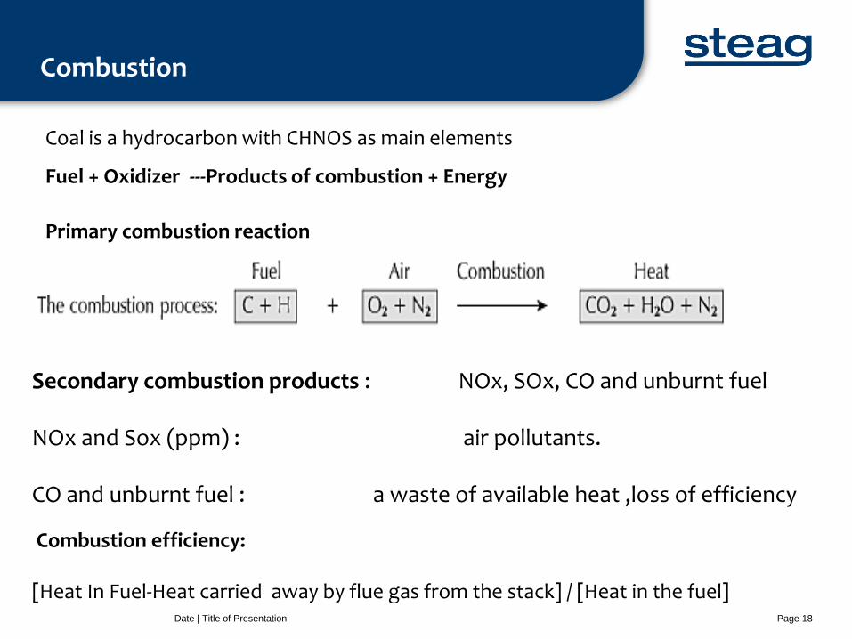
Combustion
Date | Title of Presentation Page 18
Secondary combustion products : NOx, SOx, CO and unburnt fuel NOx and Sox (ppm) : air pollutants. CO and unburnt fuel : a waste of available heat ,loss of efficiency Combustion efficiency: [Heat In Fuel-Heat carried away by flue gas from the stack] / [Heat in the fuel]
Coal is a hydrocarbon with CHNOS as main elements
Fuel + Oxidizer ---Products of combustion + Energy
Primary combustion reaction
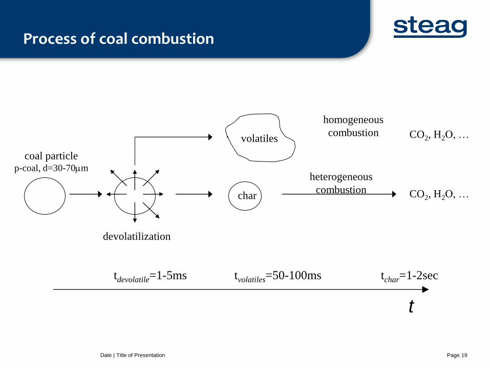
Process of coal combustion
Date | Title of Presentation Page 19
coal particle p-coal, d=30-70m
devolatilization
homogeneous
combustion
heterogeneous
combustion
CO2, H2O, …
CO2, H2O, …
tchar=1-2sec tvolatiles=50-100ms tdevolatile=1-5ms
t
volatiles
char
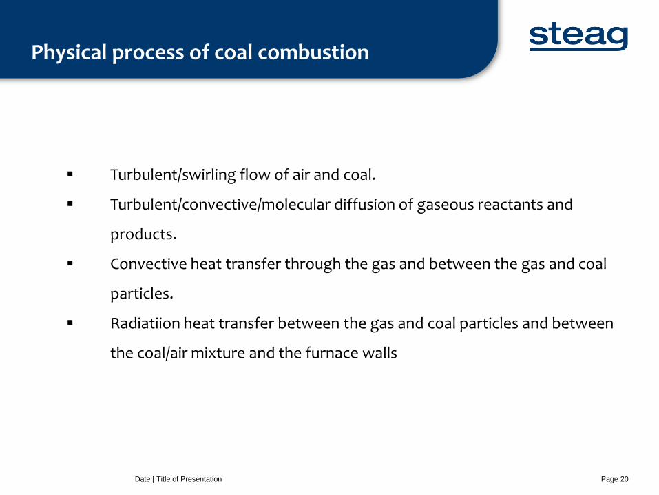
Physical process of coal combustion
Date | Title of Presentation Page 20
Turbulent/swirling flow of air and coal.
Turbulent/convective/molecular diffusion of gaseous reactants and
products.
Convective heat transfer through the gas and between the gas and coal
particles.
Radiatiion heat transfer between the gas and coal particles and between
the coal/air mixture and the furnace walls
Requirements for complete combustion
Date | Title of Presentation Page 21
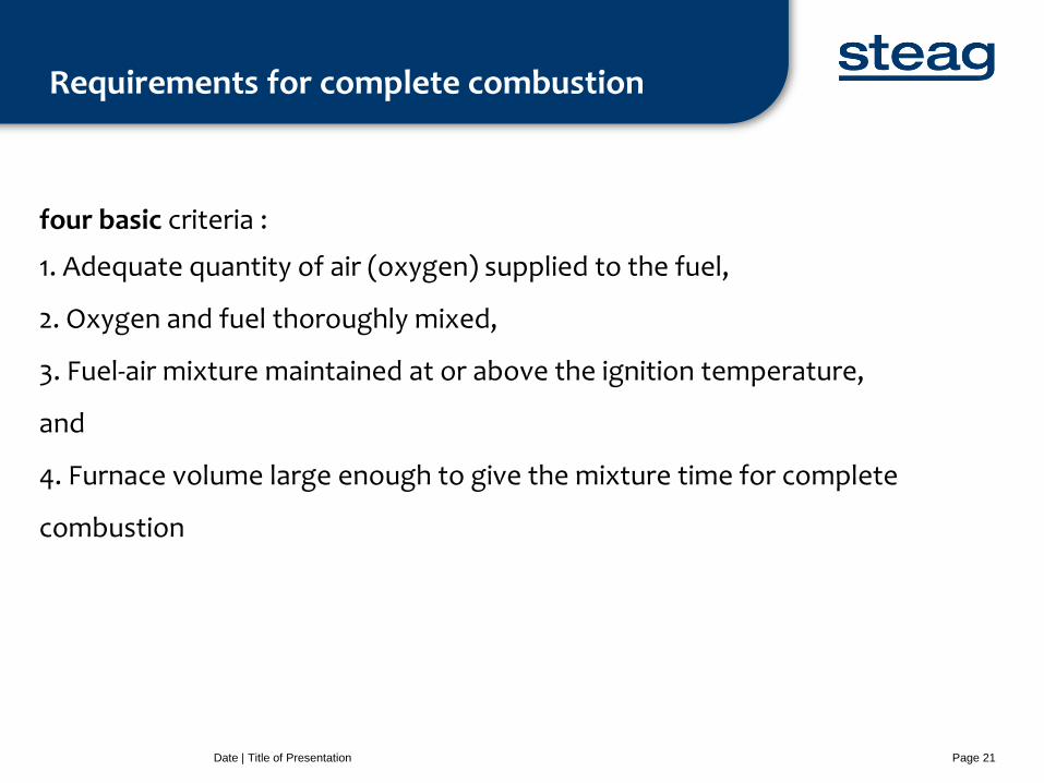
four basic criteria :
1. Adequate quantity of air (oxygen) supplied to the fuel,
2. Oxygen and fuel thoroughly mixed,
3. Fuel-air mixture maintained at or above the ignition temperature,
and
4. Furnace volume large enough to give the mixture time for complete
combustion
Air for Combustion
Date | Title of Presentation Page 22
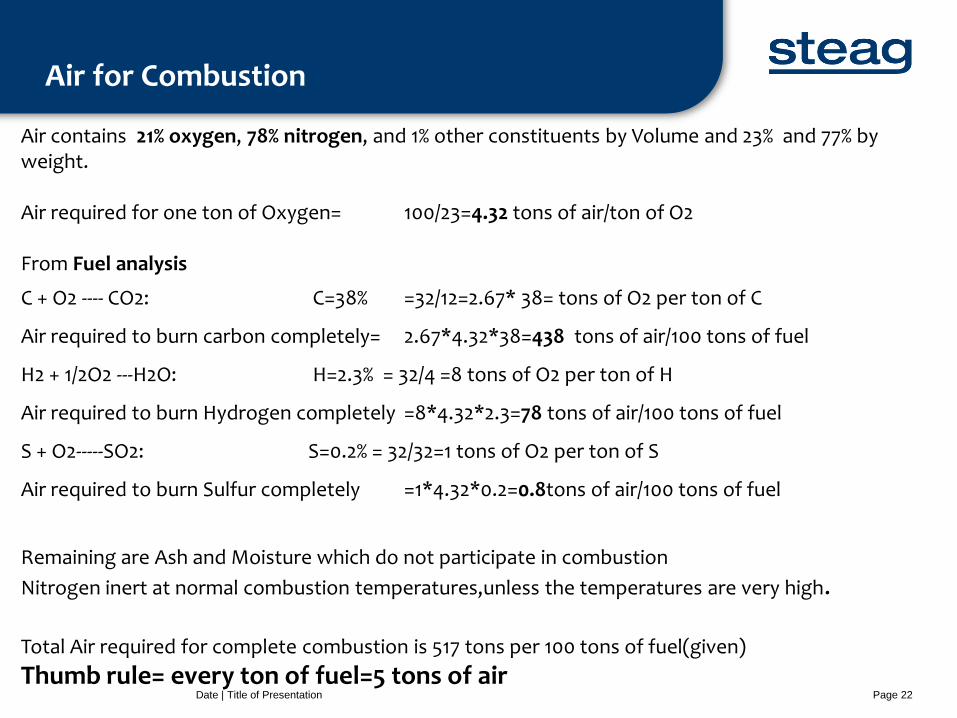
Air contains 21% oxygen, 78% nitrogen, and 1% other constituents by Volume and 23% and 77% by weight. Air required for one ton of Oxygen= 100/23=4.32 tons of air/ton of O2 From Fuel analysis
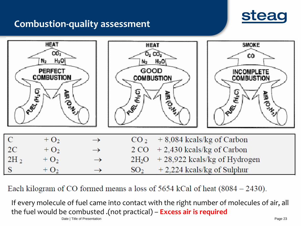
C + O2 ---- CO2: C=38% =32/12=2.67* 38= tons of O2 per ton of C
Air required to burn carbon completely= 2.67*4.32*38=438 tons of air/100 tons of fuel
H2 + 1/2O2 ---H2O: H=2.3% = 32/4 =8 tons of O2 per ton of H
Air required to burn Hydrogen completely =8*4.32*2.3=78 tons of air/100 tons of fuel
S + O2-----SO2: S=0.2% = 32/32=1 tons of O2 per ton of S
Air required to burn Sulfur completely =1*4.32*0.2=0.8tons of air/100 tons of fuel
Remaining are Ash and Moisture which do not participate in combustion
Nitrogen inert at normal combustion temperatures,unless the temperatures are very high. Total Air required for complete combustion is 517 tons per 100 tons of fuel(given)
Thumb rule= every ton of fuel=5 tons of air
Combustion-quality assessment
Date | Title of Presentation Page 23
As the temperature of the flame increases, dissociation begins; T, > 2500 K at 20 atm, dissociation of CO,and H,O occurs
If every molecule of fuel came into contact with the right number of molecules of air, all the fuel would be combusted .(not practical) – Excess air is required
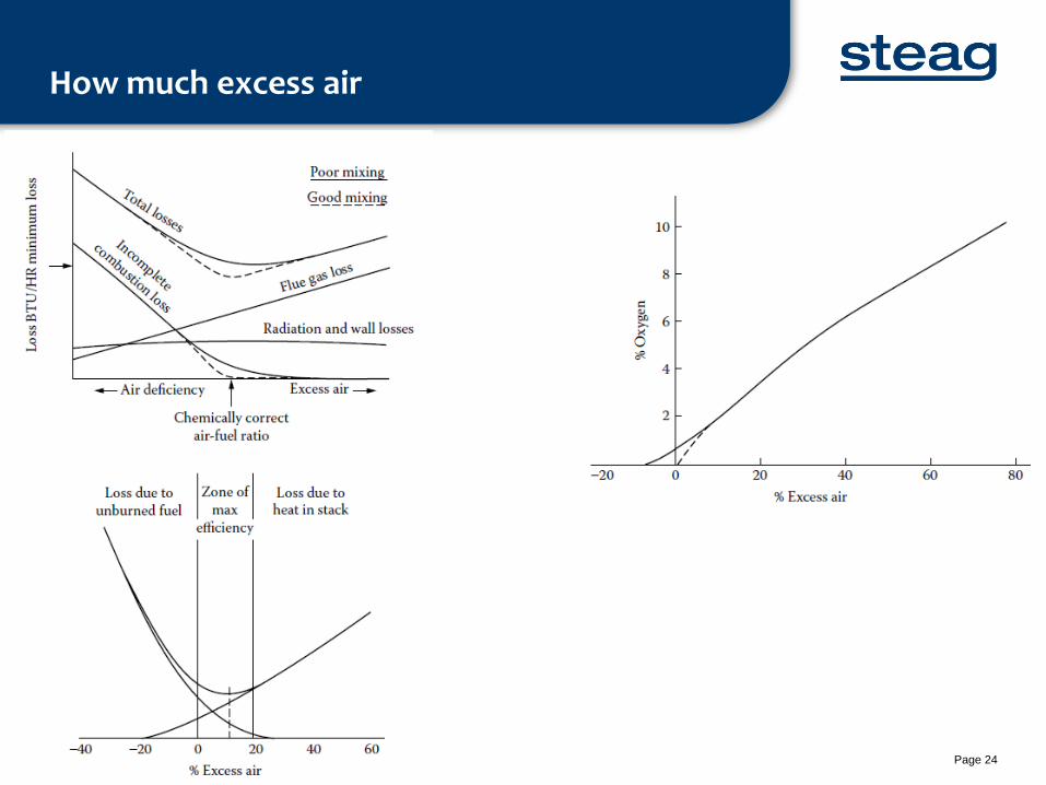
How much excess air
Date | Title of Presentation Page 24
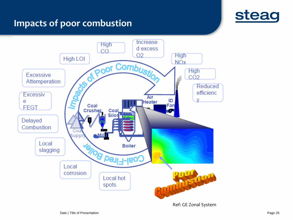
Impacts of poor combustion
Date | Title of Presentation Page 25
Ref: GE Zonal System
Reasons for improper combustion
Date | Title of Presentation Page 26
Significant quantities of air in-leakage or “tramp” air into the furnace
Improper turbulence
Improper fuel sizing
Inadequate fuel flows
Inadequate fuel velocities
Improper temperatures
Consequences: significant loss of boiler efficiency, caused by high furnace exit gas temperatures.
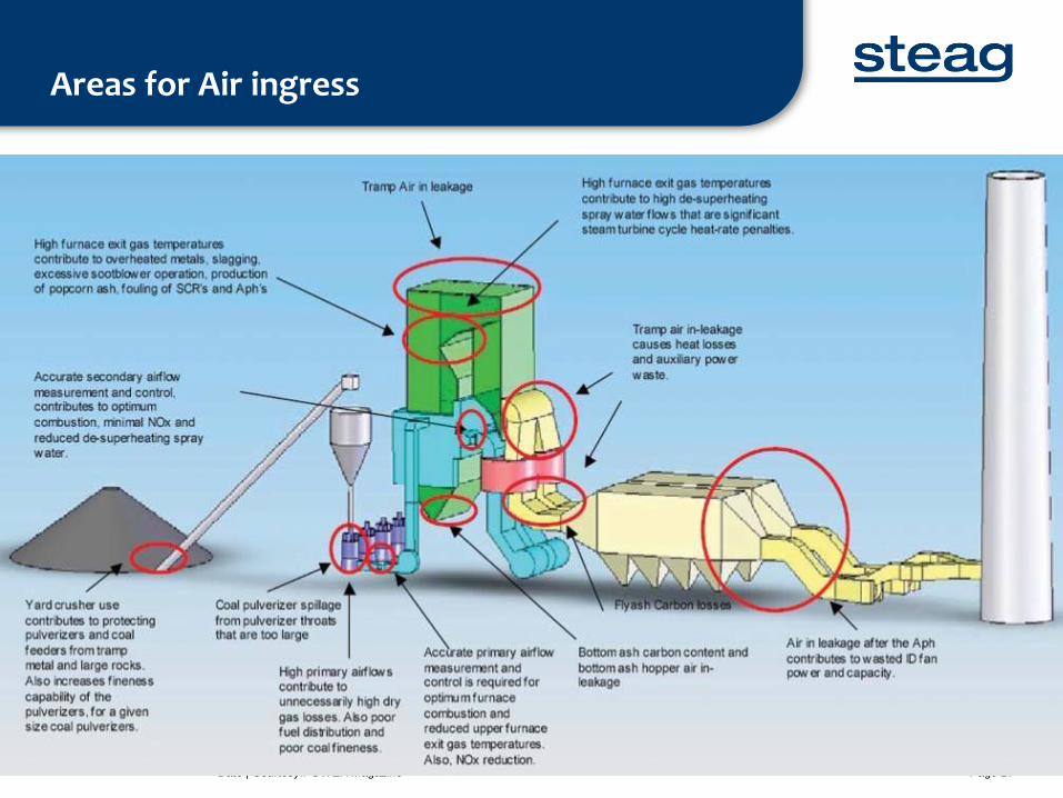
Areas for Air ingress
Date | Courtesy:POWER magazine Page 27
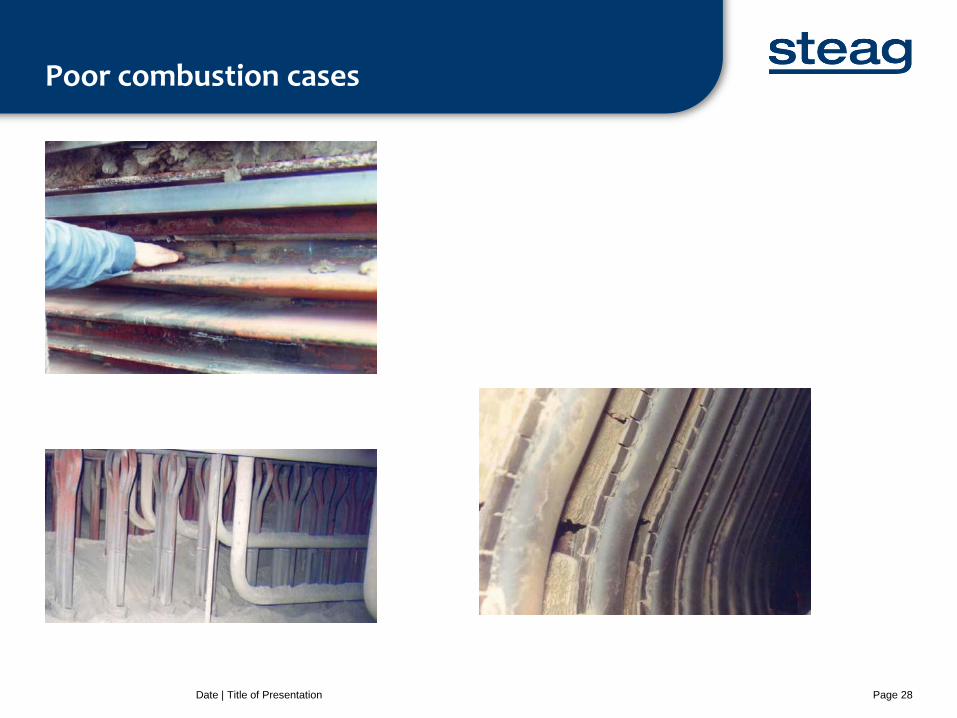
Poor combustion cases
Date | Title of Presentation Page 28
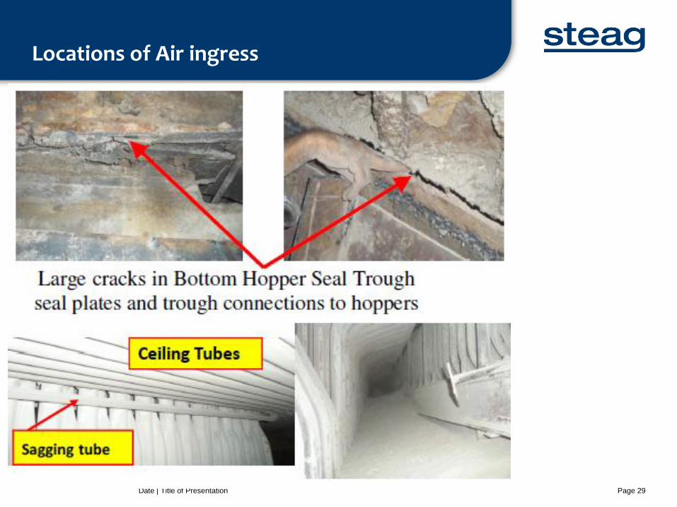
Locations of Air ingress
Date | Title of Presentation Page 29

Need for combustion optimisation
Date | Title of Presentation Page 30
Operating a boiler that is not optimised, or tuned, can
fallout of pulverised fuel, blocked pipes, or high mill pressure
erosion of mill, pipes and burner components
poor burner ignition, and flame instability and dislocation
incorrect primary and secondary air-to-fuel ratios
increased nitrous oxide production
increased levels of unburnt carbon
increased excess-air requirements
increased erosion between furnace and boiler exit
reduced boiler efficiency
localised furnace problems that can include inappropriate superheater and reheater
temperature profiles,
increased slagging and greater water-wall wastage.
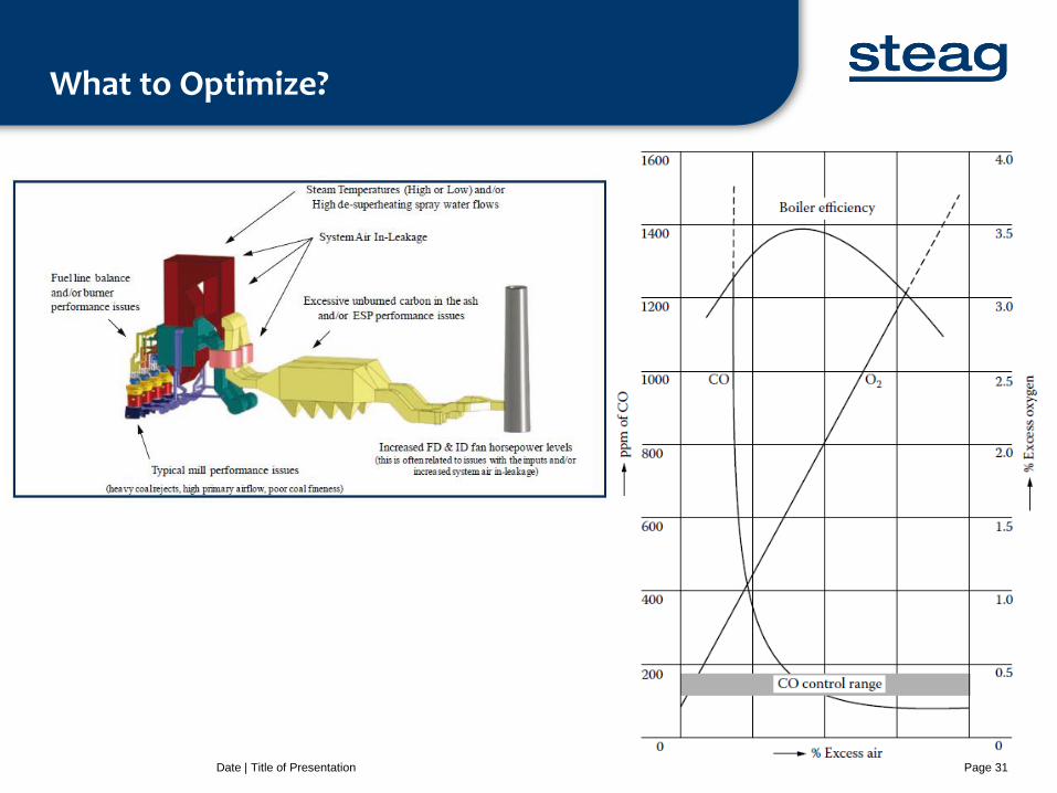
What to Optimize?
Date | Title of Presentation Page 31
Methods for Combustion optimization
• Diagnostic testing
• Sensor based
• Online Optimization
• Modeling based approach for combustion control
• Control loop tuning
Date | Title of Presentation Page 32

Diagnostic testing
Date | Title of Presentation Page 33
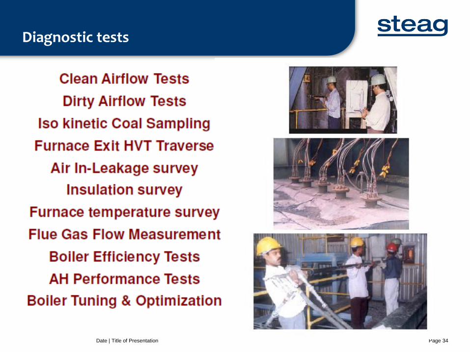
Diagnostic tests
Date | Title of Presentation Page 34
Combustion optimization based on Diagnostic testing
Date | Title of Presentation Page 35
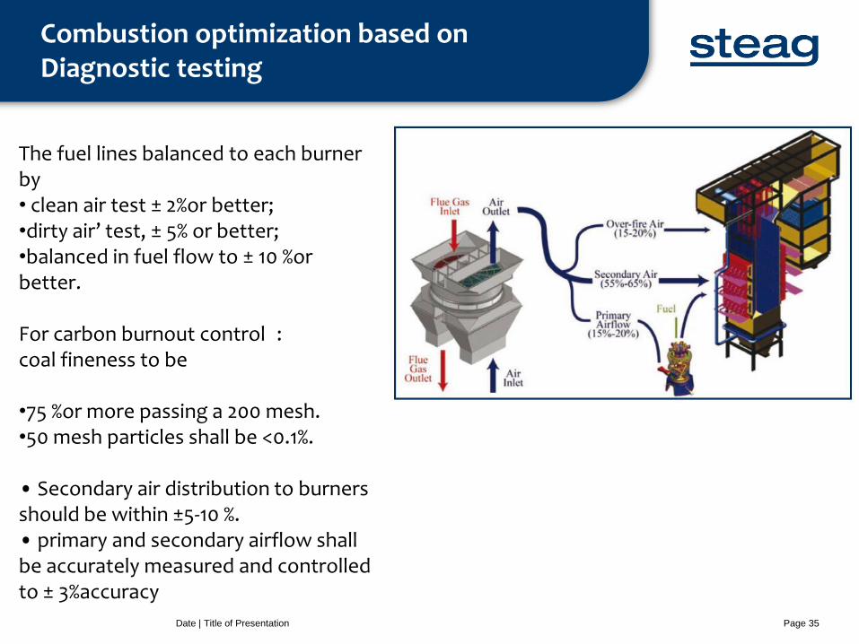
The fuel lines balanced to each burner by • clean air test ± 2%or better; •dirty air’ test, ± 5% or better; •balanced in fuel flow to ± 10 %or better. For carbon burnout control : coal fineness to be •75 %or more passing a 200 mesh. •50 mesh particles shall be <0.1%. • Secondary air distribution to burners should be within ±5-10 %. • primary and secondary airflow shall be accurately measured and controlled to ± 3%accuracy

Sensor based diagnostic and optimization
Date | Title of Presentation Page 36
CO2 sensing as combustion control
Date | Title of Presentation Page 37
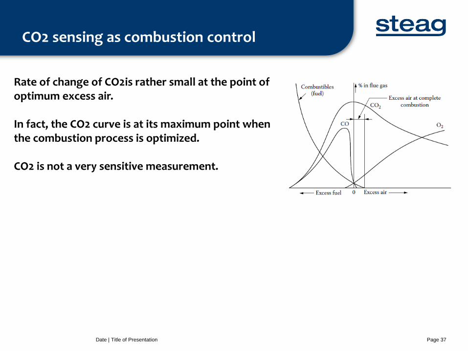
Rate of change of CO2is rather small at the point of optimum excess air. In fact, the CO2 curve is at its maximum point when the combustion process is optimized. CO2 is not a very sensitive measurement.
O2 sensing as combustion control
Date | Title of Presentation Page 38
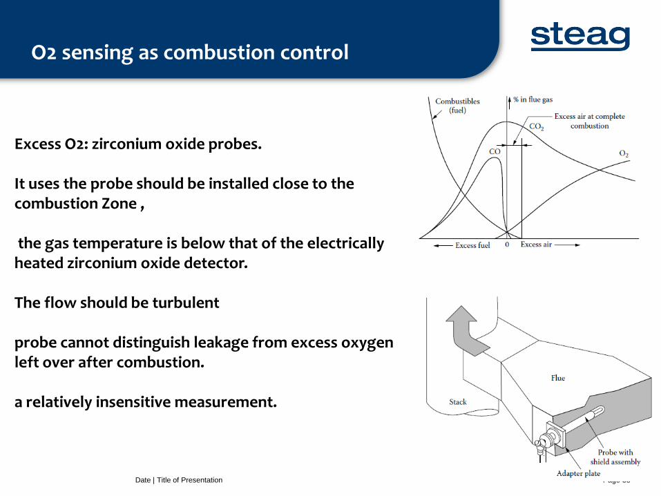
Excess O2: zirconium oxide probes. It uses the probe should be installed close to the combustion Zone , the gas temperature is below that of the electrically heated zirconium oxide detector. The flow should be turbulent probe cannot distinguish leakage from excess oxygen left over after combustion. a relatively insensitive measurement.
CO as combustion control
Date | Title of Presentation Page 39
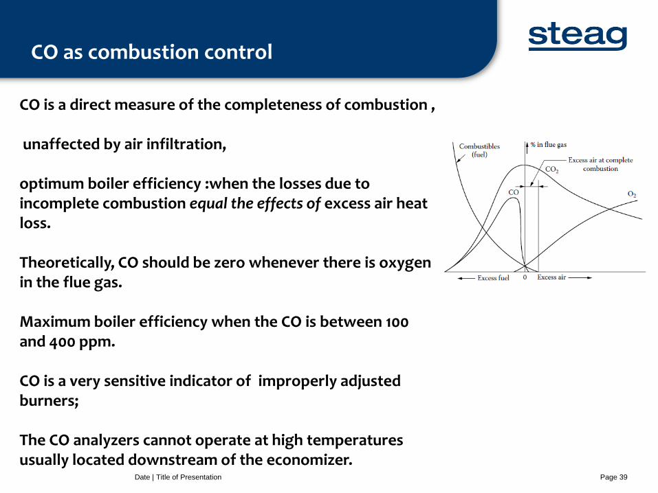
CO is a direct measure of the completeness of combustion , unaffected by air infiltration, optimum boiler efficiency :when the losses due to incomplete combustion equal the effects of excess air heat loss. Theoretically, CO should be zero whenever there is oxygen in the flue gas. Maximum boiler efficiency when the CO is between 100 and 400 ppm. CO is a very sensitive indicator of improperly adjusted burners; The CO analyzers cannot operate at high temperatures usually located downstream of the economizer.
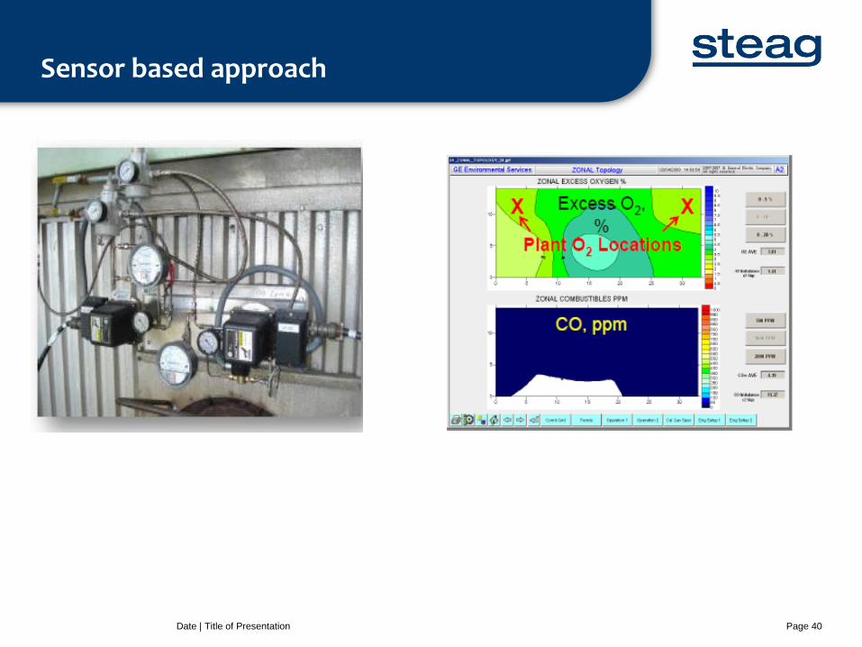
Sensor based approach
Date | Title of Presentation Page 40
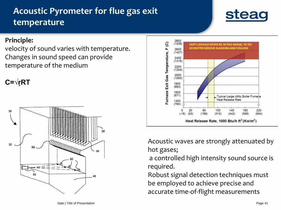
Acoustic Pyrometer for flue gas exit temperature
Date | Title of Presentation Page 41
Principle: velocity of sound varies with temperature. Changes in sound speed can provide temperature of the medium C=√ṛRT
Acoustic waves are strongly attenuated by hot gases; a controlled high intensity sound source is required. Robust signal detection techniques must be employed to achieve precise and accurate time-of-flight measurements
Combustion control through online optimization-PADO
Date | Title of Presentation Page 42
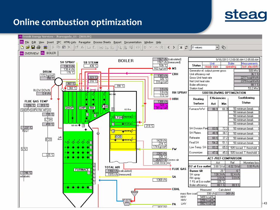
Online combustion optimization
Date | Title of Presentation Page 43
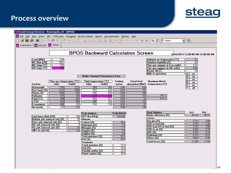
Process overview
Date | Title of Presentation Page 44
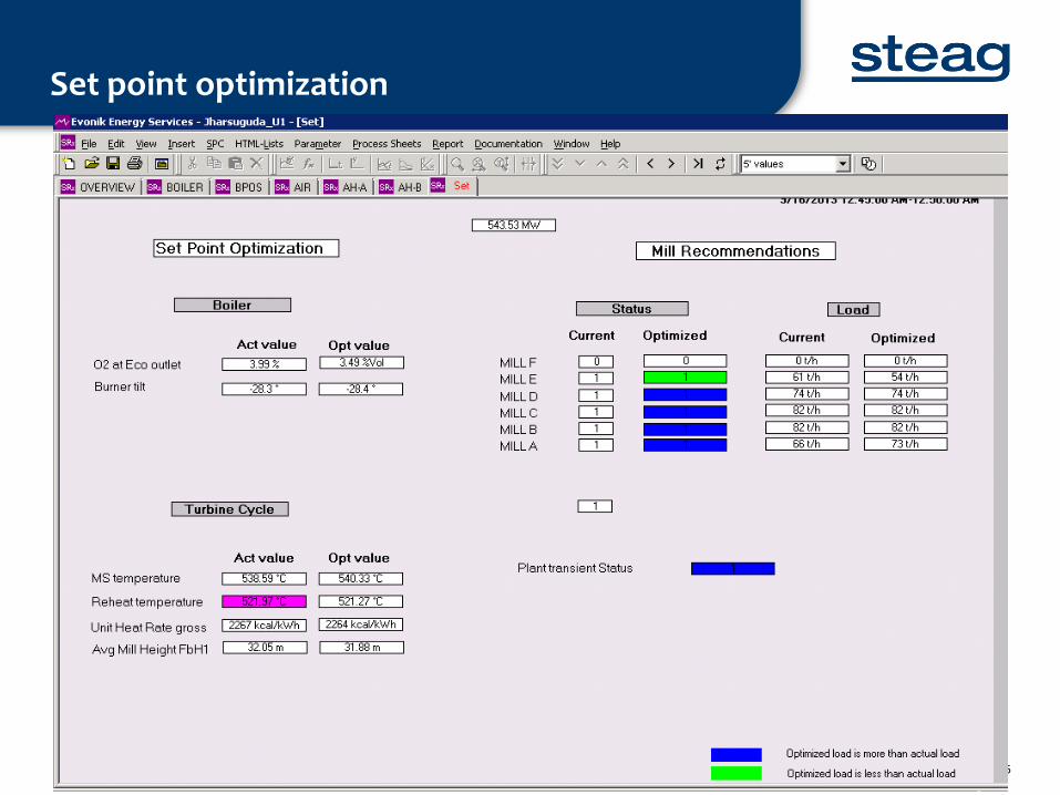
Set point optimization
Date | Title of Presentation Page 45
Combustion optimization with CFD modeling
Date | Title of Presentation Page 46

CFD model development
Date | Title of Presentation Page 47
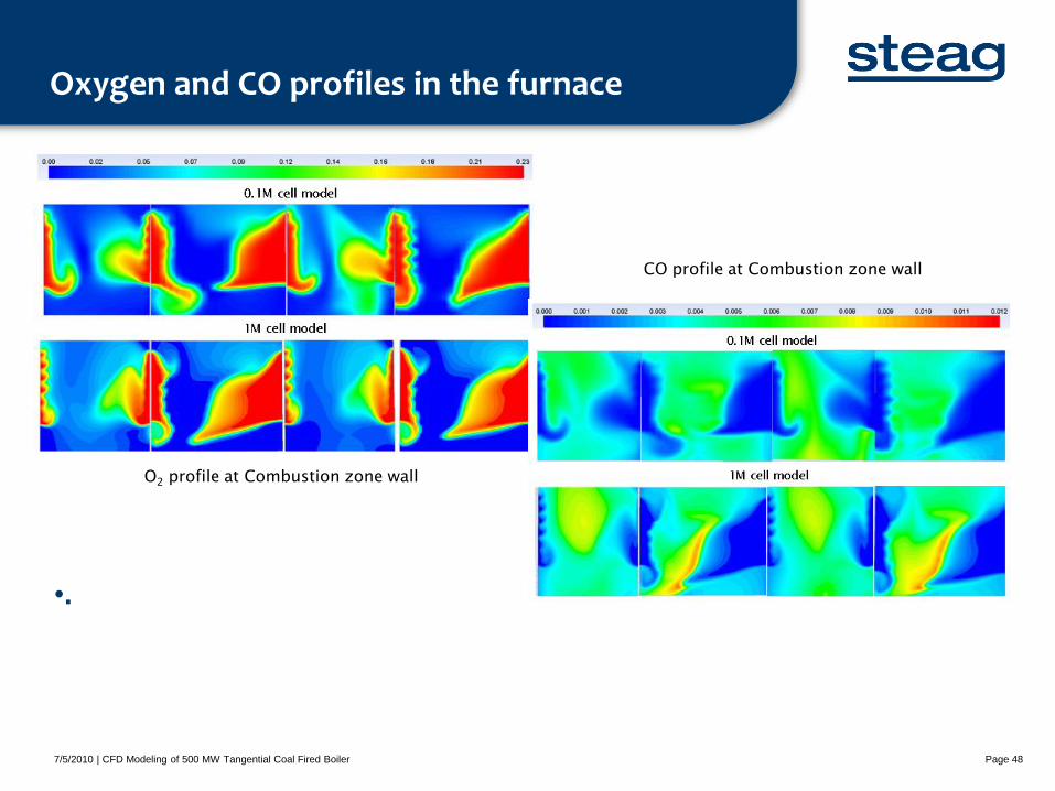
Oxygen and CO profiles in the furnace
•.
7/5/2010 | CFD Modeling of 500 MW Tangential Coal Fired Boiler Page 48
O2 profile at Combustion zone wall
CO profile at Combustion zone wall
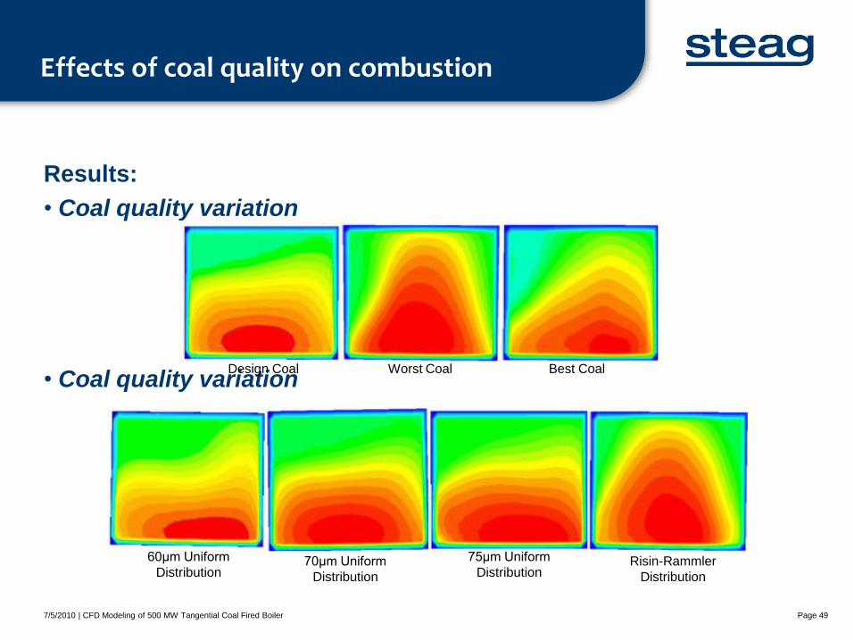
Effects of coal quality on combustion
Results:
• Coal quality variation
• Coal quality variation
7/5/2010 | CFD Modeling of 500 MW Tangential Coal Fired Boiler Page 49
Design Coal Worst Coal Best Coal
60μm Uniform
Distribution 70μm Uniform
Distribution
75μm Uniform
Distribution Risin-Rammler
Distribution
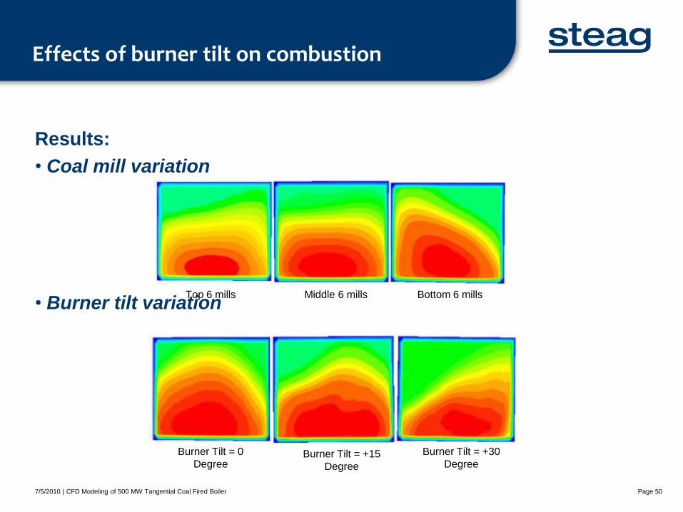
Effects of burner tilt on combustion
Results:
• Coal mill variation
• Burner tilt variation
7/5/2010 | CFD Modeling of 500 MW Tangential Coal Fired Boiler Page 50
Top 6 mills Middle 6 mills Bottom 6 mills
Burner Tilt = 0
Degree Burner Tilt = +15
Degree
Burner Tilt = +30
Degree
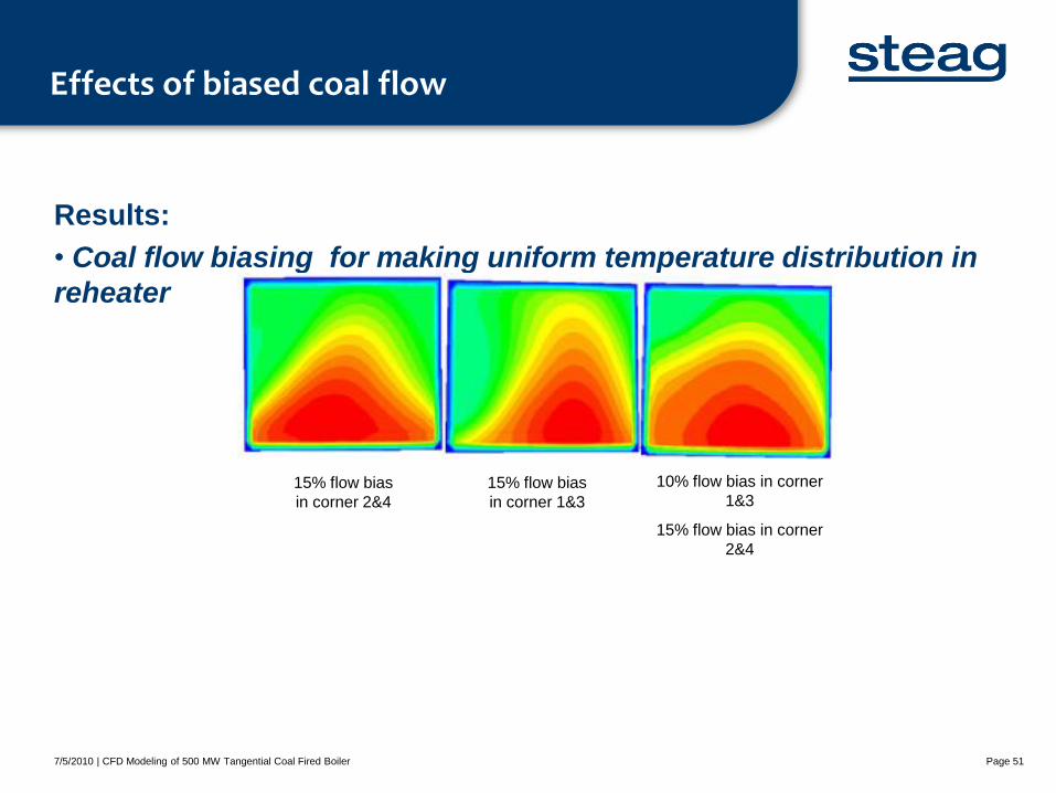
Effects of biased coal flow
Results:
• Coal flow biasing for making uniform temperature distribution in
reheater
7/5/2010 | CFD Modeling of 500 MW Tangential Coal Fired Boiler Page 51
15% flow bias
in corner 2&4
15% flow bias
in corner 1&3
10% flow bias in corner
1&3
15% flow bias in corner
2&4
Advance models for combustion optimization
Date | Title of Presentation Page 52
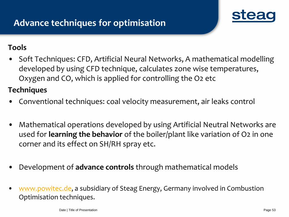
Advance techniques for optimisation
Tools
• Soft Techniques: CFD, Artificial Neural Networks, A mathematical modelling developed by using CFD technique, calculates zone wise temperatures, Oxygen and CO, which is applied for controlling the O2 etc
Techniques
• Conventional techniques: coal velocity measurement, air leaks control
• Mathematical operations developed by using Artificial Neutral Networks are used for learning the behavior of the boiler/plant like variation of O2 in one corner and its effect on SH/RH spray etc.
• Development of advance controls through mathematical models
• www.powitec.de, a subsidiary of Steag Energy, Germany involved in Combustion Optimisation techniques.
Date | Title of Presentation Page 53
Combustion Optimization through control modifications
A case study
Date | Title of Presentation Page 54
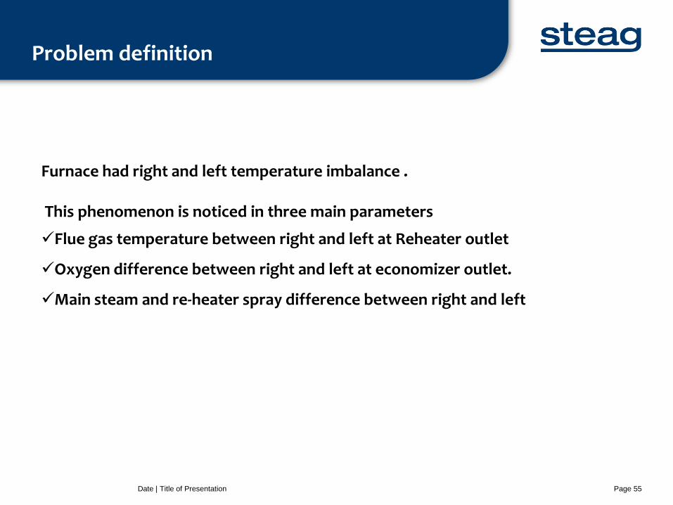
Problem definition
Date | Title of Presentation Page 55
Furnace had right and left temperature imbalance . This phenomenon is noticed in three main parameters
Flue gas temperature between right and left at Reheater outlet
Oxygen difference between right and left at economizer outlet.
Main steam and re-heater spray difference between right and left
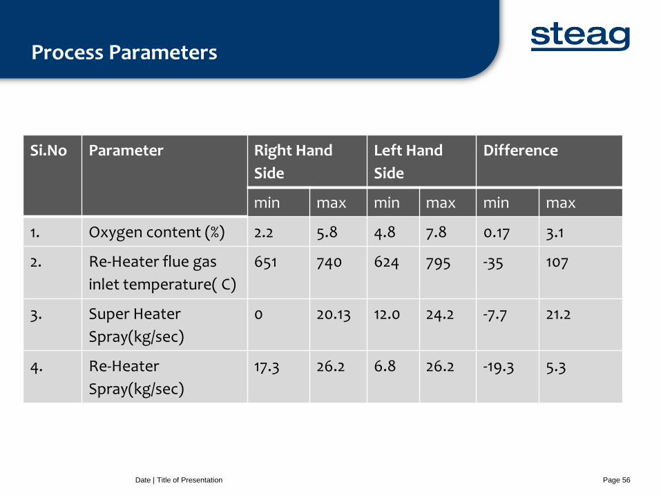
Process Parameters
Date | Title of Presentation Page 56
Si.No Parameter Right Hand
Side
Left Hand
Side
Difference
min max min max min max
1. Oxygen content (%) 2.2 5.8 4.8 7.8 0.17 3.1
2. Re-Heater flue gas
inlet temperature( C)
651 740 624 795 -35 107
3. Super Heater
Spray(kg/sec)
0 20.13 12.0 24.2 -7.7 21.2
4. Re-Heater
Spray(kg/sec)
17.3 26.2 6.8 26.2 -19.3 5.3
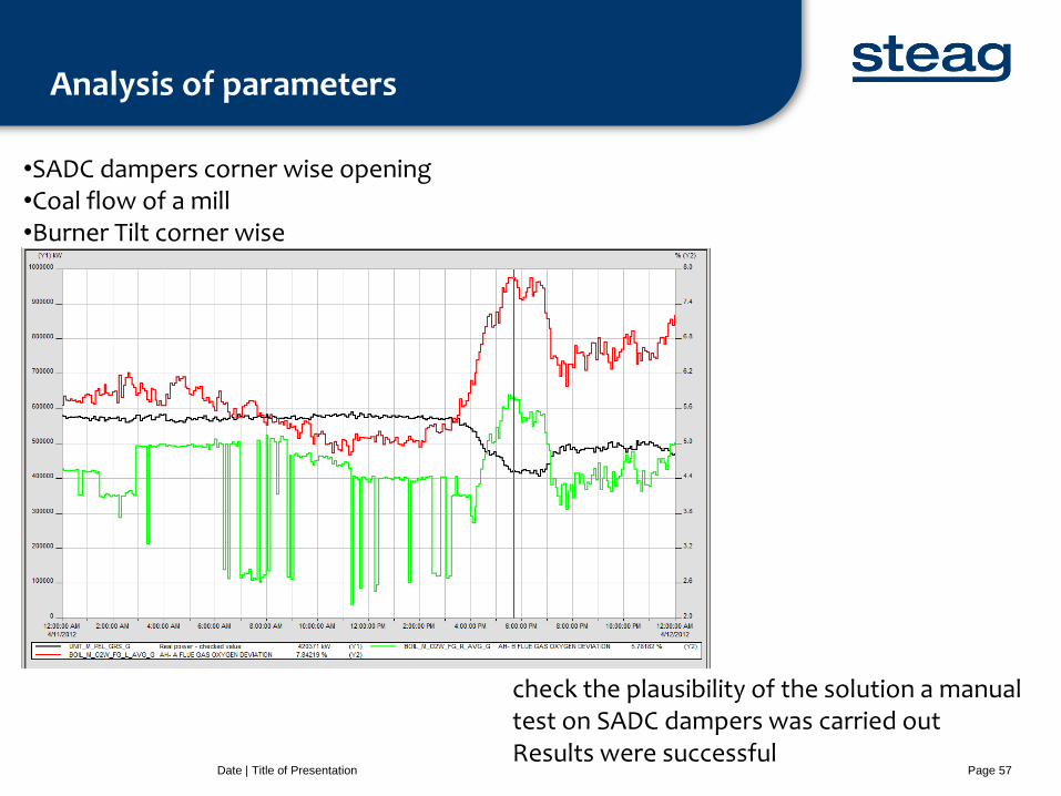
Analysis of parameters
Date | Title of Presentation Page 57
•SADC dampers corner wise opening •Coal flow of a mill •Burner Tilt corner wise
check the plausibility of the solution a manual test on SADC dampers was carried out Results were successful
CLOSE LOOP COMBUSTION TO ADAPT
Solution
Date | Title of Presentation Page 58
Closed loop combustion optimisation
Date | Title of Presentation Page 59
Steps in a closed loop combustion optimization 1. Communication: to communicate with a DCS, MODBUS (TCP/IP)
2. Control modification: different control loops Biasing the set point
3. Exploration: A process of generating a step tests to create a learning set for data
driven models (Neural Nets, Auto regression models, etc.,)
4. Defining the. Right and left imbalance is the objective
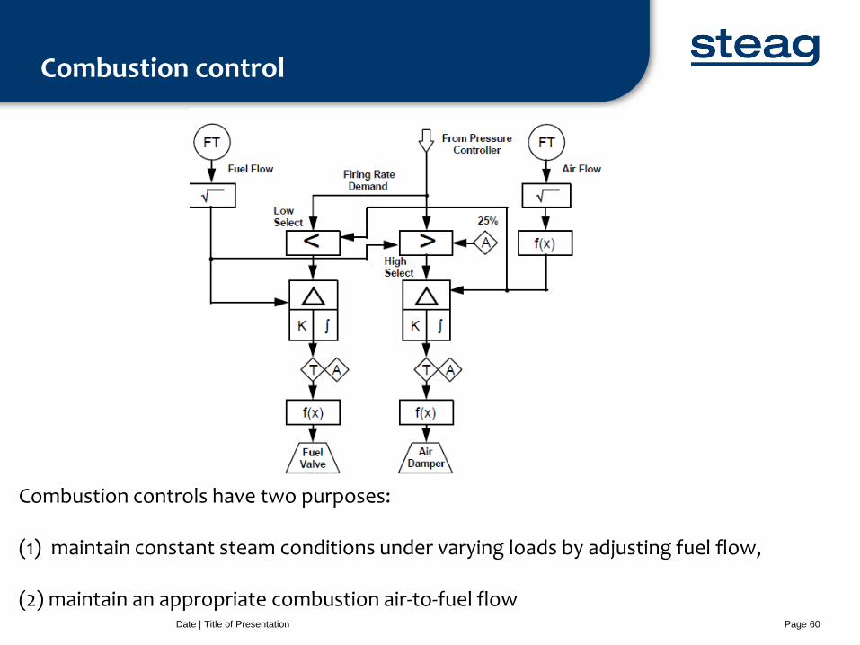
Combustion control
Date | Title of Presentation Page 60
Combustion controls have two purposes: (1) maintain constant steam conditions under varying loads by adjusting fuel flow, (2) maintain an appropriate combustion air-to-fuel flow
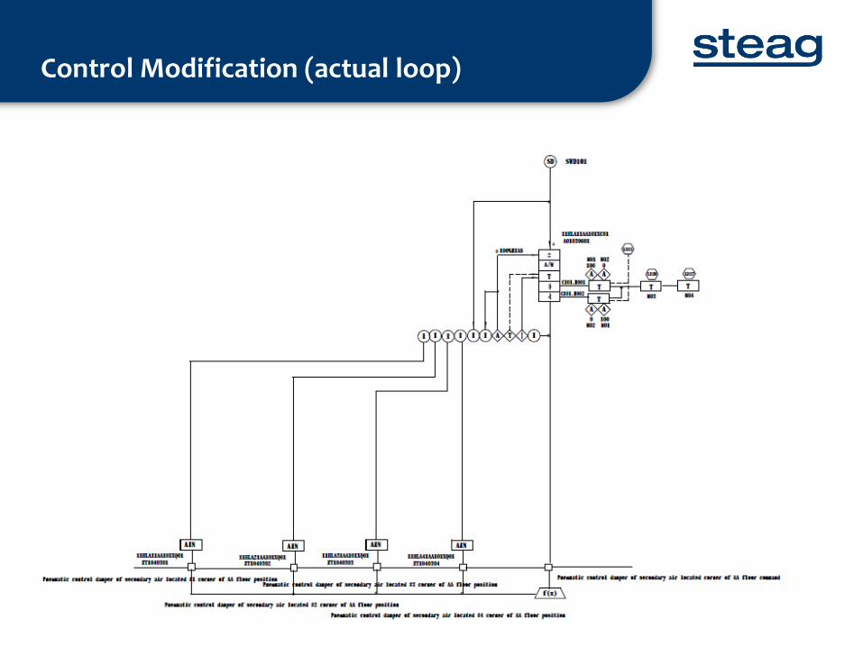
Control Modification (actual loop)

Thank
You
... Ideas & Solutions for Tomorrow