castings and defects their remedies - bangladesh...
TRANSCRIPT

CHAPTER 8
CASTING DEFECTS AND THEIR REMEDIESUnder practical conditions castings contain voids, inclusions and other imperfections which contribute to a normal quality variation. Such imperfections begin to be regarded as true defects or flaws only when the satisfactory function or appearance of the product is in question: consideration must then be given to the possibility of salvage or, in more serious cases, to rejection and replacement.
This type of decision is dependent not only upon the defect itself but upon its significance in relation to the service function of the casting and, in turn, to the quality and inspection standards being applied. The present chapter will be devoted to the causes and prevention of defects, to their significance, and finally to an appraisal of the techniques of rectification.
The general origins of defects lie in three sectors.
1. the casting design. 2. the technique of manufacture—the method, 3. the application of the technique – ‘workmanship’. A defect may arise from a single clearly defined cause which enables the remedy to be sought in one of these sectors. It may, however, result from a combination of factors, so that the necessary preventive measures are more obscure. All foundry men are familiar with the persistent defect which defies explanation and finally disappears without clarification of its original cause. Close control and standardisation of all aspects of production technique offers the best defence against such troubles.
Although the logical classification of casting defects presents great difficulties because of the wide range of contributing causes, a rough classification may be made by grouping the defects under certain broad types:
1. Shaping faults arising in pouring. 2. Inclusions and sand defects. 3. Gas defects. 4. Shrinkage defects due to volume contraction in the liquid state and during solidification. 5. Contraction defects occurring mainly or wholly after solidification. 6. Dimensional errors. 7. Compositional errors and segregation.
Although these groups are not mutually exclusive, they afford reasonably clear lines of division in most cases. Causes and remedies of defects belonging to each of the above groups are discussed hereafter. A summary of common casting defects is given in the Appendix A.
8.1 SHAPING FAULTS ARISING IN POURING
When the liquid metal enters the mould, the first requirement is that it should satisfactorily fill the mould cavity and develop a smooth skin through intimate contact with the mould surface. Gross failure to meet these conditions produces the most serious defect in this group, the misrun or short run casting, in which the metal solidifies prematurely and some limb or section of the casting is omitted. Cold laps (see Figure X-1) are a less severe manifestation of the same fault. These arise when the metal fails to flow freely over the mould surface; the intermittent flow pattern is retained on solidification due to lack of coalescence of liquid streams. Cold shuts are more serious, the discontinuity extending completely through a casting member in which streams of metal have converged from different directions.
The first sign of conditions giving rise to such defects is the occurrence of rounded corners and edges and a general lack of definition of sharp features and fine mould detail. The defects are most generally associated with metal temperature, cold metal being the usual cause in castings for which the production method is normally satisfactory. A further cause can be excessive chill from the mould face; this may arise from heavy chilling or from too high a moisture content in greensand. Laps may be encountered, for example, when a method developed for dry sand practice is used in conjunction with green sand instead.
A contributing cause to these defects can be an inadequate rate of mould filling relative to the freezing rate of the casting: especially susceptible, therefore, are extended casting of high
1

surface area to volume ratio. Slow mould filling may result from low pouring speed, from an inadequate gating system, or as a result of back pressure of gases in a badly vented mould cavity: several aspects of the casting method are therefore involved in prevention.
Figure 8.1 Cold laps and shut in a steel casting (courtesy of Institute of British Foundry men)
Alloys showing poor fluidity, especially those carrying strong oxide films, are particularly prone to defects resulting form improper flow. In these cases special techniques of gating and high superheat are the principal aids to sharp outlines and completely filled moulds.
8.2 INCLUSIONS AND SAND DEFECTSNon-metallic inclusions in castings may be considered in two main groups. The first are the indigenous, or endogenous, inclusions, the product of reactions within the melt. These are relatively small particles which remain suspended in the alloy at the time of pouring, or which may be precipitated due to changes in solubility on cooling.
The second group are the exogenous inclusions, which result from entrainment of non-metallics during pouring. These vary widely in size and type and include dross, slag and flux residues, formed and separated in the melting furnace but carried over with the metal stream; other sources are refractory fragments from furnace and ladle linings. A further group of exogenous inclusions originates in the mould itself, consisting of moulding material dislodged during closing or pouring.
8.2.1 Indigenous inclusions or Endogenous inclusions. Indigenous or endogenous inclusions are normally dispersed through out the casting and to a large extent are characteristic of the alloy and melting practice. These are formed by reactions involving common impurities such as oxygen, nitrogen and sulphur together with more reactive metallic constituents of the alloy. Oxidation reaction is deliberately promoted for refining in steel making and other metallurgical processes and final oxygen is controlled by the addition of deoxidisers before pouring. The products of defoliation are eliminated by gravity separation or fluxing and slagging which results in coalescence into large globules for a rapid separation. In case of light alloys, owing to relatively small differences in the densities of the metal and the inclusions, gravity separation is not very effective. In such cases it is important to disturb the metal surface as little as possible during melting and also treatment with suitable fluxes which absorb and dissolve suspended non-metallic. Filtration through a porous bed of granular material before casting also gives very low inclusions contents in light alloys. Melting in vacuum or inert atmosphere also reduces the inclusion content.
Indigenous inclusions represent the general condition of cast metal rather than of a particular casting and these can be minimised by maintaining soluble impurity content at low level by suitable selection of charge melting and refining technique. To some extent, these are inevitable because of shifts in melt equilibria with fall in temperature and precipitation and segregation of impurity elements can occur during freezing.
8.2.2 Exogenous InclusionsThese result from entrainment of non-metallics during melting and pouring, e.g. dross, slag and flux residues, refractory fragments from furnace and ladle lining and inclusions originating in the mould itself consisting of moulding material dislodged during closing or pouring. Such inclusions can be regarded in specific defects and can be controlled and minimised by paying
2

proper attention during melting, pouring, and mould making. Slag, dross and refractory fragments can best be prevented by retention in the furnace and by careful skimming at the pouring stage along with the use of well maintained tea pot or bottom pouring laddle.
Avoiding defects arising from moulding materials involves careful selection, proper ramming during mould making, maintenance of mould properties and characteristics as per the alloy and \its overall casting characteristics, proper design of the gating system to prevent impingement of metal against mould and core surfaces and incorporate smooth curves rather than sharp corners and abrupt changes in direction. Exogenous inclusions tend to be concentrated in certain regions of the casting such as at the upper surfaces and adjacent to the ingates and are revealed on machining or after scaling in heat treatment.
8.2.3 Erosion Scabs and Mould Crush These defects are often associated with major inclusions. An erosion scab is a rough projection formed on the casting where sand has been washed from the mould wall. Although the scab itself can be removed by fettling, its presence implies widespread inclusions within the casting.
Mould crush occurs when a mould is closed over an ill fitting core or badly finished joint surface. When the boxes are assembled and clamped, the pressure shears a section from the edge of the mould cavity, producing a large inclusion and a corresponding projection on the casting. The defect can be avoided by careful maintenance of pattern equipment to eliminate distortion and the need for manual patching.
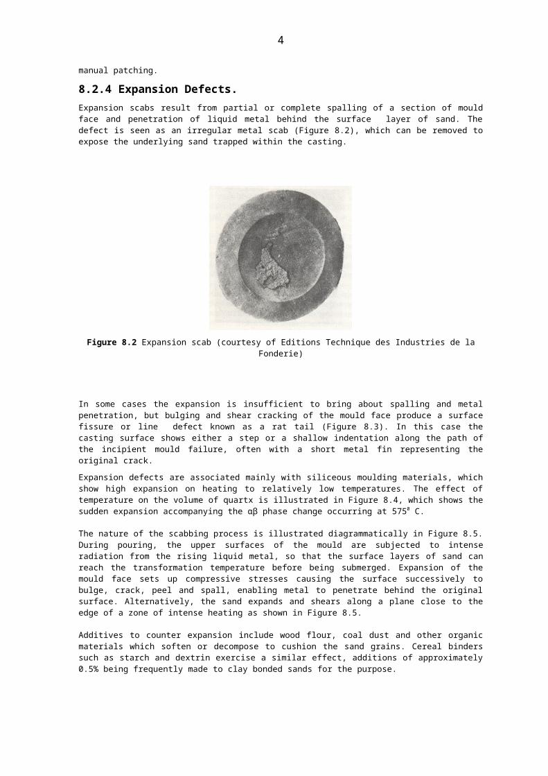
8.2.4 Expansion Defects. Expansion scabs result from partial or complete spalling of a section of mould face and penetration of liquid metal behind the surface layer of sand. The defect is seen as an irregular metal scab (Figure 8.2), which can be removed to expose the underlying sand trapped within the casting.
Figure 8.2 Expansion scab (courtesy of Editions Technique des Industries de la Fonderie)
In some cases the expansion is insufficient to bring about spalling and metal penetration, but bulging and shear cracking of the mould face produce a surface fissure or line defect known as a rat tail (Figure 8.3). In this case the casting surface shows either a step or a shallow indentation along the path of the incipient mould failure, often with a short metal fin representing the original crack.
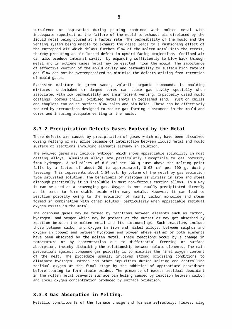
Expansion defects are associated mainly with siliceous moulding materials, which show high expansion on heating to relatively low temperatures. The effect of temperature on the volume of quartx is illustrated in Figure 8.4, which shows the sudden expansion accompanying the αβ phase change occurring at 5750 C.
The nature of the scabbing process is illustrated diagrammatically in Figure 8.5. During pouring, the upper surfaces of the mould are subjected to intense radiation from the rising liquid metal, so that the surface layers of sand can reach the transformation temperature before being submerged. Expansion of the mould face sets up compressive stresses causing the surface successively to bulge, crack, peel and spall, enabling metal to penetrate behind the
3
original surface. Alternatively, the sand expands and shears along a plane close to the edge of a zone of intense heating as shown in Figure 8.5.
Additives to counter expansion include wood flour, coal dust and other organic materials which soften or decompose to cushion the sand grains. Cereal binders such as starch and dextrin exercise a similar effect, additions of approximately 0.5% being frequently made to clay bonded sands for the purpose.
Figure 8.3Example of rat tail defect in grey iron casting (courtesy of Institute of British Foundrymen)
Figure 8.4 Effect of temperature on volume stability of quartz (from McDowell)
4
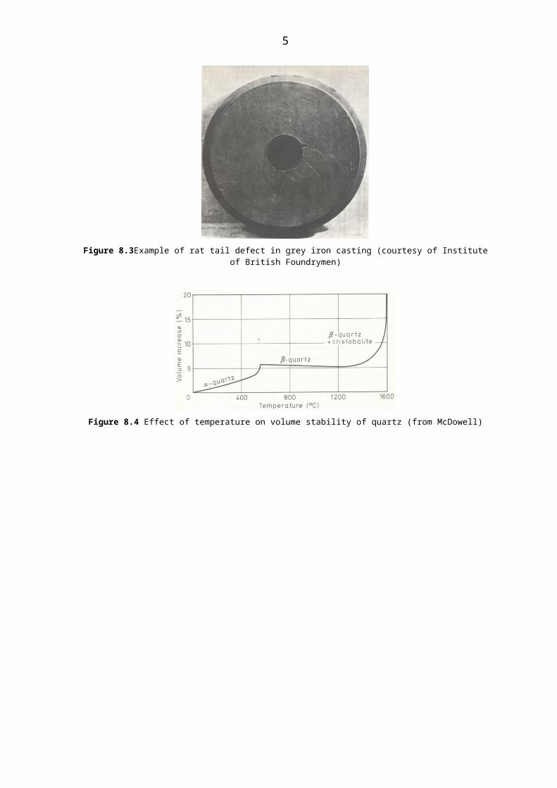
Figure 8.5 Mould expansion defects: a) scab and b) rat tail formation.
8.2.5 Surface Roughness and Sand Adherence The ideal mould would posses a smooth, impervious surface capable of being faithfully reproduced on the casting. This situation is closely approached with alloys of low melting point but at higher temperatures surface roughness and sand adhesion can be encountered, with loss of appearance and increased dressing costs. In the worst cases the moulding material becomes impregnated with metal to form a solid mass. This can be difficult to remove and if the condition occurs in a confined pocket the casting itself may be scrapped.
Since metal flow depends upon superheat, a low temperature minimises surface roughness and
5

sand adherence. In castings of very heavy section and high thermal capacity, deep penetration may result from the attainment of liquid metal temperatures to a considerable depth within the sand (Figure 8.6).
Surface quality is directly influenced by the mould material and finish, the predominant characteristic being the initial porosity: penetration is thus directly related to permeability. Low porosity can be achieved either by fine grain size, continuous grading or the use of powdered filler materials. However, mould coatings or facings enable surface porosity to be reduced without sacrificing the qualities required in the bulk material. Carbonaceous dressings containing volatile matter improve casting surfaces by generating a back pressure which opposes penetration.
a) (b)
Figure 8.6 Metal penetration (a) Direct view and (b) profiles of casting surface showing local penetration.
8.3 GAS DEFECTS Gas defects may result from entrapment of air during pouring, from evolution on contact between liquid metal and moulding material, or may be precipitated during solidification as a result either of chemical reaction or of a change in solubility with temperature.
Defects take the form of internal blowholes, surface blows, airlocks, surface or subcutaneous pinholes or intergranular cavities, depending upon the immediate cause. The gaseous origin is frequently evident from rounded contours but in some cases the shape of the cavity is governed by other factors: in the case of intergranular porosity, for example, concave walled cavities can result from constraint by solid-liquid interfaces existing at the time of precipitation.
Gas defects may be considered in two main groups: those caused by physical entrapment on pouring and those resulting form precipitation by the metal on cooling.
8.3.1 Entrapment Defects These defects arise when air is trapped within the casting owing to excessive turbulence or aspiration during pouring combined with molten metal with inadequate superheat or the failure of the mould to exhaust air displaced by the liquid metal being poured at a faster rate. The permeability of the mould and the venting system being unable to exhaust the gases leads to a cushioning effect of the entrapped air which delays further flow of the molten metal into the recess, thereby producing an air locked defect in upward facing projections. Confined air can also produce internal cavity by expanding sufficiently to blow back through metal and in extreme cases metal may be ejected from the mould. The importance of effective venting of the mould cavity and permeability to sustain high rate of gas flow can not be overemphasized to minimise the defects arising from retention of mould gases.
Excessive moisture in green sands, volatile organic compounds in moulding mixtures, underbaked or damped cores can cause gas cavity specially when associated with low permeability and insufficient venting. Improperly dried mould coatings, porous chills, oxidised
6

metal shots in reclaimed sand, rust on chills and chaplets can cause surface blow holes and pin holes. These can be effectively reduced by precautions designed to reduce gas forming substances in the mould and cores and insuring adequate venting in the mould.
8.3.2 Precipitation Defects-Gases Evolved by the Metal These defects are caused by precipitation of gases which may have been dissolved during melting or may arise because of interaction between liquid metal and mould surface or reactions involving elements already in solution.
The evolved gases may include hydrogen which shows appreciable solubility in most casting alloys. Aluminium alloys are particularly susceptible to gas porosity from hydrogen. A solubility of 0.6 cm3 per 100 g just above the melting point falls by a factor of about 20 to approximately 0.03 cm3 per 100 g. during freezing. This represents about 1.54 pct. by volume of the metal by gas evolution from saturated solution. The behaviours of nitrogen is similar in iron and steel although practically it is insoluble in most non-ferrous casting alloys. In a way it can be used as a scavenging gas. Oxygen is not usually precipitated directly as it tends to form stable oxide with many metals. However, it can lead to reaction porosity owing to the evolution of mainly carbon monoxide and steam formed in combination with other solutes, particularly when appreciable residual oxygen exists in the metal.
The compound gases may be formed by reactions between elements such as carbon, hydrogen, and oxygen which may be present at the outset or may get absorbed by reaction between the molten metal and its surroundings. Such reactions include those between carbon and oxygen in iron and nickel alloys, between sulphur and oxygen in copper and between hydrogen and oxygen where either or both elements have been absorbed by the molten metal. These reactions occur by a change in temperature or by concentration due to differential freezing or surface absorption, thereby disturbing the relationship between solute elements. The main precautions against compound gas porosity is to minimise the final oxygen content of the melt. The procedure usually involves strong oxidising conditions to eliminate hydrogen, carbon and other impurities during melting and controlling residual oxygen at the final stage by the addition of appropriate deoxidiser before pouring to form stable oxides. The presence of excess residual deoxidant in the molten metal prevents surface pin holing caused by reaction between carbon and local oxygen concentration produced by surface oxidation.
8.3.3 Gas Absorption in Melting. Metallic constituents of the furnace charge and furnace refractory, fluxes, slag making additions and furnace atmospheres may lead undesirable gas absorption. Finely divided material such as swarf and turnings contaminated with hygroscopic corrosion products and lubricants can result in high hydrogen content in the molten metal. Similarly metals from previous melting cycles or from electrolytic sources are liable to contain high hydrogen resulting from the reducing conditions employed during smelting. Refractories such as furnace spouts, tundishes, ladles, fluxes and slag making additions if not properly preheated before contact with liquid metal may lead to gas adsorption through dissociation of steam at the contact surface. Humidity and gases present in the atmosphere may also cause gas absorption which may be aggravated by conditions peculiar to the melting furnace e.g. by dissociation of gas molecules in electric are melting.
8.3.4 Metal Mould Reaction.Reactions between the metal and mould result in the formation of gases leading to porosity on the surface and such reactions are prevalent in light alloys containing magnesium and in phosphor bronze. Such reactions are caused by direct contact between an alloying constituent with high oxygen affinity and free or combined water in the mould. Aluminium-magnesium alloys are susceptible to such unsoundness and pinholing may also occur in magnesium treated spheroidal graphite cast iron which contains only minor amounts of magnesium. The metal mould reaction can be suppressed by forming a continuous surface film by introducing an alloying element with a still higher oxygen affinity than the offending element. An addition of 0.004 pct. beryllium can eliminate metal mould reaction in light sections of Al-10% Mg alloy casting and addition of small quantities of aluminium to phosphor bronzes is effective in eliminating metal mould reaction. The addition of inhibitors to the moulding sand is commonly used to prevent metal mould reaction in light alloys by replacing the oxides with another compound film. Boric acid and ammonium bifluoride are used as inhibitors and may be applied as paint coatings. The strong metal mould reaction tendency in magnesium based castings in curbed by using sands containing approximately 1 pct. sulphur along with boric acid.
7
Reaction pin holing in the case of magnesium treated iron castings can be prevented by the elimination of free moisture with the aid of clay free moulding dressings and by the use of coal dust to provide a reducing atmosphere. Metal mould reaction may cause pin holing in steel castings by the reaction of iron with free moisture in green sand to produce hydrogen which diffuses into metal. This combines with dissolved oxygen producing water vapour which leads to pin holing (Fig 8.7) . Effective deoxidation with aluminium can prevent pinholing from this and other causes.
8.3.5 Influence of Gas in Solid StateApart from the cavities formed during freezing, gas remaining in solid solution or as stable gas-metal compound can result in lowered mechanical properties or even embitterment causing cracking of the alloy owing to the reduction in solid solubility. On further cooling, the dissolved gas diffuses in existing voids and imperfections. This may generate extremely high internal pressure, with consequent increased susceptibility to fracture at much lower level of applied stress. Such stress to induce cracking may arise from the structural change or resistance tocontraction or in service itself. The embitterment caused by residual hydrogen in steel is a typical case of damage caused in solid metal by dissolved gases. Conventionally such a susceptibility
Figure.8.7 Pinhole Porosity (Courtesy of W . J . Jackson)
was eliminated by prolonged high diffusion treatment in the solid state. However, it is now possible to produce gas free metal by precautions and vacuum treatment during melting and casting.
8.3.6 Preventive Measures for Gas DefectsThese may be broadly discussed as follows: (i) Low gas content in the molten metal when poured can be achieved by carefully
designed melting techniques and precautions such as (a) Using selected grade raw materials from known sources with low gas content.
Contaminated materials are processed separately for the preliminary removal of gas before they are used with the main charge.
(b) Preheating the charge material to evaporate surface moisture and volatilise oils, paints or other organic contaminants as well as water of crystallisation from hydrated corrosion product.
(c) Treatment of turnings and borings from machine shop in special degreasing plant incorporating a centrifuge followed by treatment with organic solvents. Such a treatment is justified in case of expensive alloys.
(d) Employing fast melting techniques and the use of compact charges to reduce the time of gas metal contact in melting. Such a practice also minimises melting losses.
8

(e) In copper and nickel alloys as well as steels, maintenance of oxidising condition is beneficial for the removal of dissolved hydrogen. However, this is not suitable for removing hydrogen from melts containing appreciable amount of aluminium, magnesium or similarly reactive elements. Protective fluxes are employed to minimise gas metal contact and undue absorption of hydrogen.
(f) Final alloy additions should be completely dry and gas free and the temperature of the molten metal should be maintained at the lowest level to ensure adequate fluidity during pouring and casting. The holding time should be reduced to minimum and furnace spouts, ladles, and furnace tools should be preheated to eliminate moisture and the danger of gas absorption at the final stage.
Vacuum melting can be considered for the production of gas free metal by excluding atmospheric contamination, extracting dissolved gas to the influence of reduced pressure, eliminating elements which precipitate compound gases during freezing and preferentially evaporating elements with high vapour pressure. Inspite of the clear technical advantages in vacuum melting, it has found limited application in the production of castings because of the constraints of higher cost and scale of operation. Its use is confined for the production of high duty precision castings in special alloys where quality requirements justify a substantial premium on the selling price.
8.3.7 Degassing of Molten Metal By careful material selection and observing proper precautions during melting, the absorption of gas can be reduced, but it is difficult to avoid the presence of gases in melt under routine foundry conditions. Making use of the equilibrium existing between melt and gas atmosphere, following types of degassing treatment before pouring are practised:
(a) Gas ScavengingThe flushing gas is bubbled through the melt, thereby providing a large gas metal interface and general agitation. In the case of aluminous alloys, argon, nitrogen or chlorine can be employed to reduce hydrogen absorption. Calcium carbonate which generates CO2 is used for gas scavenging in case of copper base alloys. During steel making the oxygen injected for the removal of carbon and other elements also reduces the hydrogen and nitrogen contents of the melt. The CO boil in steel making is also valued for its effect in eliminating dissolved gases.
(b) Oxidation, Deoxidation and Precipitation of compounds. During the melting of iron, copper and nickel alloys, the liquid metal is exposed to oxidizing conditions which increase the concentration of dissolved oxygen in the melt. This is beneficial for the removal of hydrogen by direct chemical reaction to from H2O molecules. Deoxidation before pouring is accomplished by the addition of suitable elements which form stable oxides. Stabilisation of the impurity by precipitation as a compound can be employed for reducing nitrogen particularly in nickel base alloys. Formation of stable nitrides of lithium, titanium and zirconium effectively suppresses nitrogen pinholing in such alloys.
(c) Vacuum Degassing General processes of vacuum degassing have been developed all of which depend on decreased gas solubility in molten metal by reduction of the external pressure. This is in accordance with Sievert’s law which can be represented as following.
s = K √(p1-p2)where s = Amount of gas dissolved in an alloy cm3/100 gm.
K = solubility constant dependent on temperatureP1 = partial pressure of gas in the surrounding atmosphere.
and P2 = partial pressure of gas in the melt.
The rate of degassing depends partly on the geometry of the system, i.e. the surface area and the mass of the metal and partly upon the extent of the agitation and stirring which help in the transport of the dissolved gas to the nearest surface. A number of processes have been developed for use on an industrial scale which include: (a) static bath treatment (b) induction degassing (c) fractional degassing and (d) stream droplet degassing as illustrated in Fig. 8.8
The static bath treatment involves enclosure of the molten metal ladle in a chamber which is sealed and evacuated, often assisted by induction stirring which helps in bubble formation.
9

Fractional degassing involves treatment of fraction of the molten metal which is raised through a section nozzle into a vacuum chamber by alternate raising and lowering of the chamber. In stream droplet degassing, a ladle is tapped through a sealed annulus into a second ladle kept in a previously evacuated chamber. Exposure of the falling stream to vacuum results in gas evolution owing to the formation of small droplets.
Figure 8.8. Techniques of vacuum degassing of liquid metals. (a) static bath,(b) inclusion degassing, (c) fractional degassing, (d) stream droplet degassing
In special cases however, advantage is derived from limited gas evolution on freeing, e.g., in some copper alloys with long freezing range, gas evolution obtained from controlled mould reaction can produce a wide dispersion of microporosity rather than a more localised void concentration, this being beneficial for pressure tightness. In case of die casting of aluminium alloys, controlled gas evolution is employed to cause slight expansion of the casting. This helps to offset the linear contraction which may lead to hot tearing under restraint.
8.4 SHRINKAGE DEFECTS
Shrinkage defects arise from failure to compensate for liquid and solidification contraction, so their occurrence is usually a symptom of inadequate gating and risering technique. The actual form of defect depends upon design factors, cooling conditions and the mechanism of freezing of the alloy. Various types of internal cavity of surface depression are encountered: these are illustrated schematically in Figure. 8.9 and some examples are shown in Figures 8. 10 to 8.11
10
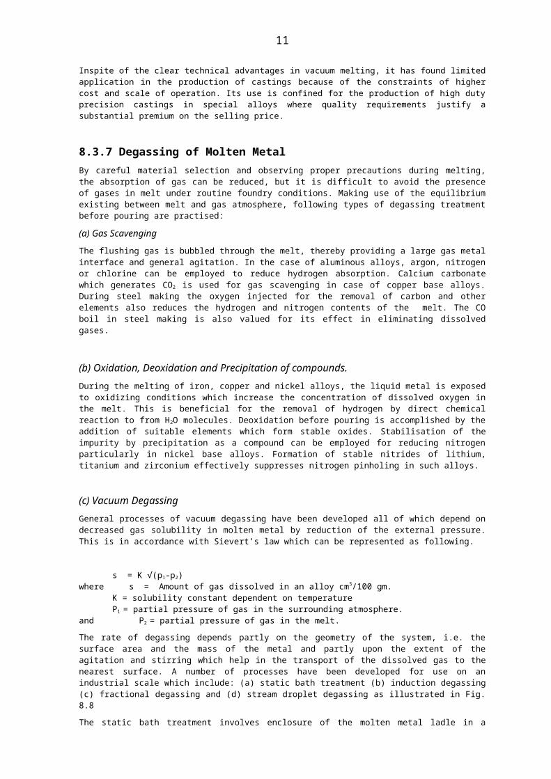
Figure 8. 9 Forms of Shrinkage defect. (a) Primary pipe. (b) Secondary cavities. (c) Discrete porosity. (d) Sink. (e) Puncture.
8. 4.1 Major Shrinkage Cavities
Sharply defined cavities occur primarily in those alloys which solidify by skin formation and result either from premature exhaustion of the supply of feed metal or from failure to maintain directional solidification throughout freezing. The most conspicuous example is the primary shrinkage cavity or pipe resulting form an inadequate feeder head: due to lack of feed metal the final pipe extends into the casting, becoming visible on head removal (figure 8. 9 a).
Sporadic occurrence in a casting with a well established method must be attributed to some change in practice, for example omission of a feeding compound or cessation of pouring before the head was completely filled; drastic changes in pouring speed or casting temperature are other possible causes. Since the defect is localised rectification by welding is sometimes feasible.
Unlike primary shrinkage, secondary shrinkage is wholly internal and occurs in positions remote from the feeder head. Depending on the severity of the conditions, the defect may be a massive cavity or a filamentary network. Typical sites include the central zones of extended parallel walled sections and local section increases where no provision has been made either for direct fed or selective chilling (Figure 8.9b) Although this form of cavity is inaccessible for repair, its location near to the neutral axis of stress diminishes its influence on the strength of the casting. Typical examples of internal shrinkage cavities are seen in Figures 8.10 and 8.11
Figure 8.1o Centre line shrinkage in plate section
11

Figure 8.11 Sectioned casting exhibiting internal shrinkage cavity and sink
8.4.2 Discrete porosity
Alloys such as bronzes, gun metal, many light alloys and phosphorous containing cast irons are susceptible to scattered shrinkage porosity. These alloys have generally larger freezing range and the scattered porosity takes the form of intercrystalline cavities occuring in a large zone and in many cases this extends to the surface. The problem is further aggravated by the gases, rejected from the metal on freezing, which tend to oppose capillary feeding.
Scattered porosity can cause leakage under hydraulic pressure and can also adversely influence mechanical properties particularly the ductility. Micro shrinkage can neither be detected radiographically nor by visual examination of machined surfaces. Such porosity can however be inferred from ultrasonic signals and density measurement. Such porosity can be minimised considerably by appropriate design and chilling action.
8.4.3 Sinks and Surface Punctures Deformation of the casting surface by atmospheric pressure can manifest itself as a depression which may become evident only on dimensional checking. In extreme cases a local puncture on the surface can occur. Such a situation arises when the residual liquid becomes isolated from the atmosphere by a continuous thin envelope of solid. Owing to low pressure conditions occuring within the casting in such a case, the atmospheric pressure causes sinking of the surface (Fig.8.11). The surface puncture is most likely to occur with high pouring temperature. These defects can be avoided by accelerating the formation of strong surface layer by local chilling and by ensuing access of atmospheric pressure to molten metal in the feeder head.
12

8. 5 CONTRACTION DEFECTS
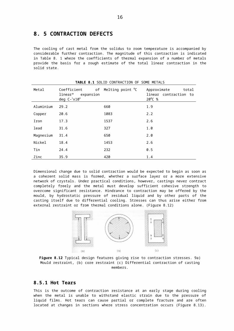
The cooling of cast metal from the solidus to room temperature is accompanied by considerable further contraction. The magnitude of this contraction is indicated in Table 8. 1 where the coefficients of thermal expansion of a number of metals provide the basis for a rough estimate of the total linear contraction in the solid state.
TABLE 8.1 SOLID CONTRACTION OF SOME METALS
Metal Coefficient of linear* expansion deg C-1x10⁶
Melting point 0C Approximate total linear contraction to 200C %
Aluminium
Copper
Iron
lead
Magnesium
Nickel
Tin
Zinc
29.2
20.6
17.3
31.6
31.4
18.4
24.4
35.9
660
1083
1537
327
650
1453
232
420
1.9
2.2
2.6
1.0
2.0
2.6
0.5
1.4
Dimensional change due to solid contraction would be expected to begin as soon as a coherent solid mass is formed, whether a surface layer or a more extensive network of crystals. Under practical conditions, however, castings never contract completely freely and the metal must develop sufficient cohesive strength to overcome significant resistance. Hindrance to contraction may be offered by the mould, by hydrostatic pressure of residual liquid and by other parts of the casting itself due to differential cooling. Stresses can thus arise either from external restraint or from thermal conditions alone. (Figure 8.12)
Figure 8.12 Typical design features giving rise to contraction stresses. 9a) Mould restraint, (b) core restraint (c) Differential contraction of casting members.
8.5.1 Hot Tears This is the outcome of contraction resistance at an early stage during cooling when the metal is unable to withstand elastic strain due to the pressure of liquid films. Hot tears can cause partial or complete fracture and are often located at changes in sections where stress concentration occurs (Figure 8.13). Alloys with very short freezing range are comparatively free from tearing tendency whereas alloys with a comparatively large temperature range of freezing are more vulnerable. Susceptibility to hot tearing is also influenced by segregation of alloying elements and impurities. Micro segregation or coring aggravates the critical period of weakness of hot tearing because of prolonged retention of intergranular liquid film with consequent increase in the accumulated strain, e.g. the serious lowering resistance to hot tearing caused by high sulphur and phosphorous contents in steel.
Design and production factors have significant influence on hot tearing owing to effects upon temperature distribution which governs the distribution of mechanical properties and resistance to concentration. To minimise susceptibility to hot tears, a number of specific precautions have to be observed in the casting design namely section uniformity, gradual
13

changes in section and providing adequate radii at all corners to reduce stress concentration, Webs and brackets are provided as reinforcements across critical regions to accelerate cooling through the critical temperature range and strengthen vulnerable zones. such reinforcements may be removed in fettling or may be retained as permanent feature of the design. For sharing the stress concentration in members vulnerable to hot tearing corrugated surfaces may provided.
8.5.2 Cracking distortion and residual stressAfter cooling below the tearing temperature, resistance to cooling of the casting for most alloys and rates of cooling can be accommodated by continuous elastic deformation. During this stage fracture can occur only if the cooling rate is so rapid as to cause the ultimate sterss of the alloy to be exceeded. Usually during such a phase of cooling, dimensional errors can occur through failure so contract to rule and such minor errors on critical dimensions are usually corrected satisfactorily by appropriate machining allowances.
The casting may retain a high level of residual stress specially where sections are of widely varying thickness. These residual stresses are proportional to Young’s Modulus, coefficient of expansion and the temperature difference between the members. In case of poor ductility of the alloy, the residual stresses can cause fracture in extreme cases during the late stage of cooling (Figure 8.14). The residual stresses make the casting vulnerable with respect to both strength and dimensional stability and a small super imposed stress such rough handling or local heating during head removal, grinding or welding can lead to creaking/ fracturing. Castings with residual stress are dimensionally unstable and many change either spontaneously with time or if heating occurs in service. Residual stresses can be removed by heat treatment and the temperature required for the rapid stress relief generally lies in the region 0.3-0.4 Tm where Tm is the melting temperature of the alloy expressed in K. It is helpful some times to withdraw castings from the mould while still in the plastic region and charge it immediately into a hot furnace where cooling can be controlled and equalised throughout the critical period. Stress relief of castings has been attempted by ageing or weathering for long periods before use. While ageing at an ambient temperature, brings about some dimensional changes, its effectiveness is uncertain and probably accounts for the relief of only a small proportion of residual stress.
8.6 DIMENSIONAL ERRORS
Pattern making, moulding and casting or fettling, if not properly carried out, give rise to dimensional faults. Major defects are due to misalignment of mould parts and cores such as cross jointing and displaced cores, wornout pains and pinholes which produce lateral shift along the joint line. Dimensional errors can be considerably reduced by a high standard of box maintenance and jig checking at regular intervals for pin
Figure 8. 13 Typical hot tear at change of section (courtesy of Editions Techniques des Industries de la Fonderie)
14

centre dimensions and for pin and pin hole clearances. By proper attention to core print design and clearances, defects from misplaced or ill fitting cores can be greatly minimised.
Figure. 8.14 Typical cold crack or clink in a casting ( Courtesy editions Techniques des Industries de la Fonderie)
Distortion of mould involving enlargement green of mould cavity during pattern withdrawal, manual patching, low green strength and soft ramming, lack of rigidity in the assembled mould, inadequately reinforced cores or badly rammed mould parts, core shifts, swelling, and growth across the joint line permit movement owing to pressure and buoyancy force on casting. high pressure moulding and hardening of moulds and core in contact with the pattern has reduced the incidence of such distortion considerably.
8.7 COMPOSITIONAL ERRORS AND SEGREGATION These defects can arise: (a) from loss of reactive elements during melting and (b) compositional differences arising during solidification and persisting in cast structure.
Alloys with strong segregation tendency usually have long freezing range, gentle liquids slope, and low solid solubility. Such segregation may be present as intergranular or dendrite segregation (micro segregation) following the form of the grain or substructure. These can affect tensile strength, ductility, impact and fatigue resistance and other mechanical properties which are affected by intercrystalline conditions which differ from the matri8.
Segregation on a macroscopic scale is produced by various mechanisms during freezing of the alloys. Normal type of segregation may result from progressive concentration of the impurities towards the centre of the casting. Differences in density of the precipitated phases as compared with the parent liquid can cause gravity segregation where as non-metallic inclusions generally rise to from local concentration. Susceptibility to gravity segregation is markedly enhanced in heavy sections because solid phases can be suspended in the liquid for prolonged time. Another form of macrosegregation called inverse segregation occurs by flow of solute rich liquid through interdendritic channels from deeper regions within the casting. Thus a high concentration of a solute appears in the outer zone in place of central region of the casting. Coarse columnar dendritic structure is particularly susceptible to inverse segregation because of the relatively straight capillary feed passages. Local differences in composition get aggravated since the outside zone also contains the purest solid in the first crystals to freeze.
15
Homogenisation treatment consisting of reheating the casting and keeping it at high temperature for a prolonged period helps to remove concentration gradient by diffusion. The spacing of the compositional variation and the highest possible temperature of homogenisation consistant with other metallurgical requirements help to increase the diffusion considerably. However, because of the large distances involved, practically there is no possibility of eliminating macro segregation by heat treatment.
8.8 SIGNFICANCE OF DEFECTS
The significance of the casting defects has to be evaluated in the context of the function of the casting and its appearance, the former being of overiding importance. The characteristics of importance are:
(i) Mechanical properties. (ii) Hydraulic soundness and (iii) Surface finish.
(i) Mechanical PropertiesFor a proper appreciation of the influence of defects on mechanical properties, the size, shape and position of the defect have to be assessed in the context of the stress pattern in the casting. The following generalised discussion will highlight the relevance and importance of the different factors involved.
(a) Freedom from surface defects and proper surface finish is particularly important under fatigue condition because generally the skin of the casting contains regions of highest stress.
(b) A flaw on an extensive flat surface is generally regarded less harmful than one occurring at change of section where an appreciable applied stress concentration is anticipated. Defects like centre line porosity or segregation located close to a neutral axis of stress are considered less severe. However, their detection and radical repair is more difficult because of inaccessible location.
(c) Any defect introduces a stress concentration, however, such a risk increases manifold with irregularity of the defect, e.g., a fine crack as compared to a spherical defect such as a blow hole or slag inclusions.
(d) The presence of a large number of small defects can influence the mechanical properties depending upon metallurgy of individual alloy and the location and the distribution of the defect. Decision regarding using the casting or discarding it can be taken in the context of specific service conditions.
(ii) Hydraulic SoundnessCastings like hydraulic cylinder, valves and pipe works are tested under pressure to demonstrate their capacity for the retention of fluids under high pressure and many copper and nickel base alloys are prone to inter granular porosity and resulting leakage because of their long freezing ranges. Proper control of feeding and gas content can largely eliminate such defects.
(iii) Surface Finish This is important to ensure proper appearance as also for castings which operate under corrosive conditions where surface pits or inclusions can form nuclei for corrosive attack. Surface imperfections become more marked after honing, polishing, enamelling, plating and anodising.
8.9 SALVAGE AND RECTIFICATION
Although salvaging of castings can be undertaken by restoring the properties and service performance to a standard equivalent to that: (a) no defects were present or (b) to improve the
16

appearance in such cases where the defects do not impair the performance. However, such a consideration should not bring about an indiscriminate relaxation of standard in the different stages of production. In general, rectification processes in crease cost, consume time, and undermine the confidence of the user. In mass production of castings such as light castings, a few defective castings are scrapped and replaced because of the high cost and inconvenience of salvage operation. However, in case of heavy castings or when production of few castings of a particular type is involved, it becomes more difficult to eliminate defects completely and the cost of rejecting the casting may involve high financial loss. In such cases salvaging the castings and making them serviceable is justified.
Depending upon the objective in view regarding the salvaging of the casting i.e., restoration of properties and for improvement in appearance, different techniques are used which include welding, brazing and soldering, caulking and impregnation, patching and plugging, filling compounds etc.
Welding Rectification of defects by welding if properly carried out and followed by appropriate post welded heat treatment can give properties fully equivalent to those of originally cast metal. By welding a true metallurgical union between filler metal land the parent casting is achieved giving continuity of crystal structure across the original interface. This is usually not possible with other methods of rectification including soldering and brazing where the union is only superficial.
Rectification by welding involves the observance of the following steps and precautions.
(i) For proper matching of the weld with the parent casting, for good corrosion resistance, appearance as well as mechanical properties, it is advisable to use a filler metal of approximately the same composition as that of the casting. A difference in hardness or colour gets revealed on machined surfaces.
(ii) It is necessary to remove completely the defective material from the casting because any attempt to weld over porous metal can result in gas evolution and porous weld deposit. Cracks if not completely removed can get further aggravated owing to thermal stresses during welding. It is therefore imperative to remove the defect completely by grinding or machining or by gouging with arc, gas flame, or chisel before executing the repair successfully irrespective of the processes to be used.
Brazing and Soldering Brazing is employed for such parts and components that tend to get distorted or cracked when welding at high temperature. In such cases the entire process is carried out below the melting point of the casting using a low melting alloy as filler. There is little penetration into the parent metal and the hardness and colour of the filler alloy are usually different. This method is used for making castings water tight and to repair pipes and pipe fittings and other thin plate tight castings, for filling crevices, porosity, fine cracks etc., Copper and nickel base alloys and silver solders with melting temperatures above 4300C are employed as fillers for brazing. Use of brazing flux is commonly based on borax and barites and fluorides of the alkali metals is necessary to remove tenacious oxide film for satisfactory brazing. These fluxes being highly corrosive, are carefully removed before the casting is put into service.
Soldering is carried out by employing lower melting point alloys based on tin, lead, cadmium and zinc which melt at much lower temperature. The process is confined to filling of minor surface cavities and other imperfections, when high strength is not required, such as making porous area in copper base alloys pressure tight.
Patches and PlugsIn some cases, the defective zone of the casting is remove by machining or drilling and then inserting a plug for final sealing of the aperture by tapping and threading and finally finishing by pinning or tack welding. Apart from rectification of defective castings, this method is used for the final sealing of temporary core print apertures in the original casting.
17

ImpregnationTo fill pin holes blow holes, cracks, etc. resin impregnation under pressure is undertaken while the casting is kept under vacuum. The compound is finally cured usually by thermal treatment to produce an inert and stable filling. This method is widely accepted to make pressure tight castings in ferrous and nonferrous metals, particularly for those alloys specially prone to micro porosity.
Filling Compound Non-metallic compounds are compounds, containing metallic powders and epoxy plastic fillers are used for rectifying surface finishes to improve appearance and also fill up pin holes, blow holes, cracks, etc. It is possible to develop appreciable strength by using epoxy and acrylic resins which strongly adhere to metals. However, such materials should not be regarded as suitable for structural repairs in view of their fundamentally different characteristics from those of cast metals.
Metal SprayingThe process consists of blowing out small drops of molten metal (melted by an electric are or gas flame) using compressed air with the help of spray fun. The metal coating obtained varies from 0.3 to 0.8 mm. in thickness, each pass giving a coat of metal about 0.03 mm thick. The method is suitable for building up undersize casting and all types of metals can be sprayed. As the bond obtained is of mechanical type with negligible diffusion, the strength of the sprayed metal is inferior to the obtained by welding or brazing. This technique is also used to improve the corrosion resistance or iron and steel castings by spraying anticorrosive metal layer.
Straightening Rectification of deformed or warped castings can be carried out by straightening in a press by applying pressure. Since the procedure involves plastic deformation, this operation is possible only in case of metals possessing reasonable ductility, Generally a hydraulic press is used with appropriate press fixtures and packing to achieve the correct final dimensions.
18

APPENDIX A TO CHAPTER XCATALOGUE OF CASTING DEFECTS AND REMEDIES
DEFINITION
1. Blow holes or gas holes: They are generally rounded cavities spherical, flattened or elongated caused by the entrapped air or gas formed during the casting process. These are generally found inside the castings.
Porosities are caused by steam or gas passing through the metal. Sometime pin hole size porosities may be present on the entire surface or just below the surface.
Blisters are shallow holes on the surface with a thin film of metal over it.
2. Scars are generally caused on a flat surface where entrapped gas has prevented the mould cavity from being filled completely. Plates are formed when metal oozes into a scar. Minor defects of the scar or cold shut is known as seam.
Cold slots or shot iron (in case of grey cast iron) are small globules of metal embedded in due to the action of the entrapped gas or air.
3. A shrinkage cavity or depression, large or small, results from varying rates of contraction while the metal is changing from liquid to solid. A minor depression is known as sink.
4. Hot tears and cracks are surface discontinuity or fractures caused by either external or internal tresses or a combination of both acting on the casting.
5. Hardness defects-mass hardness: It is caused when the entire casting is too hard. Localized hardness is called hard spot and/or chilled spots.
6. A misrun is due to failure of the metal to fill the mould cavity. The cold shut defect is caused due to imperfect fusion where two streams of metal have converged.
7. Inclusions are the non-metallic particles of materials embedded in the metal.
8. Sand defects:
(a) An erosion scab occurs where the metal has been agitated, boiled, or has partially eroded away the sand leaving a solid mass of sand and metal at that particular spot. Cuts and washes are caused due to erosion of sand causing rough spots from either excess metals or sand inclusions.
(b) Expansion scabs are rough thin layers of metal partially separated from the body of the casting by a thin layer of sand and held in place by a thin vein of metal. They may be readily chipped off causing indentation known as buckle. A raftail is a minor buckle occurring as a small irregular line or lines.
A pulldown is a buckle in the cope. A blacking scab is caused due to sand expansion. Expansion defects are governed by the extent to which the initial expansion of the quartz can be offers by deformation of the sand mass under compressive stresses. Thus the relationship between hot deformation and confined expansion test results have been found to give a measure of scabbing tendency.
9. Mould metal reaction defects:
(a) Sticker or rat is a lump on the surface of a casting caused by a portion of the mould face sticking to the pattern.
(b) Rough surfaces are caused due to minor mould metal reactions. Metal penetration is a surface defect which looks as though the metal has filled the voids between the sand grains without displacing them. When sand is fused on the surface of the casting the defect is known as fusion.
10. Defects due to faulty workmanship:
(a) A mould shift results in a casting which does not match at parting lines. A core shift results from misalignment of cores in assembling. A specialized case of core shift known as “core raise” is caused due to core movement towards the cope causing a variation in wall thickness.
(b) A ramoff or ramaway is a defect which results from a section of the mould being forced away from the pattern by ramming sand after it has conformed to the pattern contour. It may be renewable on a localised swell or shifts.
(c) Swells, fins, strains and sags result in the castings not being true to the pattern because the
19
metal section are greater or less than required. A swell is an increase in metal section due to the displacement of sand by metal pressure. A fin is a thin projection of metal from the casting.
A strain is a type of swell wherein the mould surface has cracked and permitted the metal to form a fin.
A sag is a decrease in metal section due to sagging of the cope or core.
(d) Runouts and bleeders: Sometimes called breakouts, these defects result in a casting lacking completeness due to molten metal draining or leaking out of some part of the mould cavity either during (known as runouts) or after pouring (known as bleeders).
(e) Crushes, push-ups and damp-offs: These defects occur as indentations in the casting surface due to displacement of sand in the mould.
A drop is a defect in a casting due to a portion of the sand dropping from the cope or other overhanging section.
11. Open grain structure is a defect wherein a casting when machined, appears too course grained for the application. The structure may be general or it may be localised.
12. Miscellaneous defects like broken castings are caused during handling the metal and may be due to design defect.
Inverse chills or reverse chills are caused due to inhomogeneity of metal.
Kish is a defect when in grey cast iron, free graphite has separated out from molten iron. Warpage defect is a deformation in a casting other than due to contraction that develops between solidification and room temperature.
20

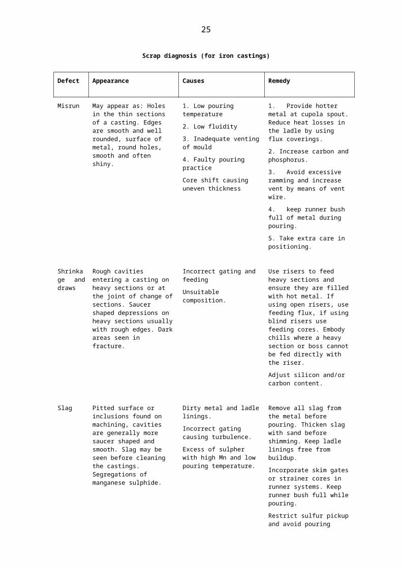
Scrap diagnosis (for iron castings)
Defect Appearance Causes Remedy
Misrun May appear as: Holes in the thin sections of a casting. Edges are smooth and well rounded, surface of metal, round holes, smooth and often shiny.
1. Low pouring temperature
2. Low fluidity
3. Inadequate venting of mould
4. Faulty pouring practice
Core shift causing uneven thickness
1. Provide hotter metal at cupola spout. Reduce heat losses in the ladle by using flux coverings.
2. Increase carbon and phosphorus.
3. Avoid excessive ramming and increase vent by means of vent wire.
4. keep runner bush full of metal during pouring.
5. Take extra care in positioning.
Shrinkage and draws
Rough cavities entering a casting on heavy sections or at the joint of change of sections. Saucer shaped depressions on heavy sections usually with rough edges. Dark areas seen in fracture.
Incorrect gating and feeding
Unsuitable composition.
Use risers to feed heavy sections and ensure they are filled with hot metal. If using open risers, use feeding flux, if using blind risers use feeding cores. Embody chills where a heavy section or boss cannot be fed directly with the riser.
Adjust silicon and/or carbon content.
Slag Pitted surface or inclusions found on machining, cavities are generally more saucer shaped and smooth. Slag may be seen before cleaning the castings. Segregations of manganese sulphide.
Dirty metal and ladle linings.
Incorrect gating causing turbulence.
Excess of sulpher with high Mn and low pouring temperature.
Remove all slag from the metal before pouring. Thicken slag with sand before shimming. Keep ladle linings free from buildup.
Incorporate skim gates or strainer cores in runner systems. Keep runner bush full while pouring.
Restrict sulfur pickup and avoid pouring “dull” iron.
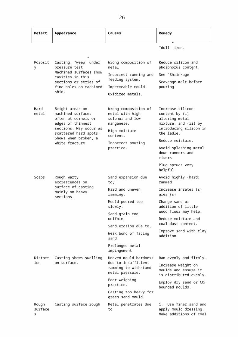
Porosity Casting, “weep” under pressure test. Machined surfaces show cavities in this sections or series of fine holes on machined shin.
Wrong composition of metal.
Incorrect running and feeding system.
Impermeable mould.
Oxidized metals.
Reduce silicon and phosphorus content.
See “Shrinkage”
Scavenge melt before pouring.
Hard metal
Bright areas on machined surfaces often at corners or edges of thinnest
Wrong composition of metal with high sulphur and low manganese.
Increase silicon content by (i) altering metal mixture, and (ii) by
21

Defect Appearance Causes Remedy
sections. May occur as scattered hard spots. Shows when broken, a white fracture.
High moisture content.
Incorrect pouring practice.
introducing silicon in the ladle.
Reduce moisture.
Avoid splashing metal down runners and risers.
Plug sprues very helpful.
Scabs Rough warty excrescences on surface of casting mainly on heavy sections.
Sand expansion due to,
Hard and uneven ramming.
Mould poured too slowly.
Sand grain too uniform
Sand erosion due to,
Weak bond of facing sand
Prolonged metal impingement
Avoid highly (hard) rammed
Increase inrates (s) area (s)
Change sand or addition of little wood flour may help.
Reduce moisture and coal dust content.
Improve sand with clay addition.
Distortion
Casting shows swelling on surface.
Uneven mould hardness due to insufficient ramming to withstand metal pressure.
Poor weighing practice.
Casting too heavy for green sand mould.
Ram evenly and firmly.
Increase weight on moulds and ensure it is distributed evenly.
Employ dry sand or CO2 bounded moulds.
Rough surfaces
Casting surface rough Metal penetrates due to
1. Moulding sand ‘too’ open
2. Low coal dust content.
3. Uneven ramming.
1. Use finer sand and apply mould dressing. Make additions of coal dust. Ram more evenly.
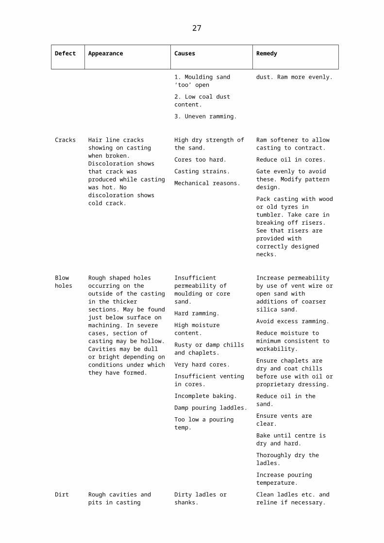
Cracks Hair line cracks showing on casting when broken. Discoloration shows that crack was produced while casting was hot. No discoloration shows cold crack.
High dry strength of the sand.
Cores too hard.
Casting strains.
Mechanical reasons.
Ram softener to allow casting to contract.
Reduce oil in cores.
Gate evenly to avoid these. Modify pattern design.
Pack casting with wood or old tyres in tumbler. Take care in breaking off risers. See that risers are provided with correctly designed necks.
Blow holes
Rough shaped holes occurring on the outside of the casting in the thicker sections. May be found just below surface
Insufficient permeability of moulding or core sand.
Hard ramming.
Increase permeability by use of vent wire or open sand with additions of coarser silica sand.
Avoid excess ramming.
22

Defect Appearance Causes Remedy
on machining. In severe cases, section of casting may be hollow. Cavities may be dull or bright depending on conditions under which they have formed.
High moisture content.
Rusty or damp chills and chaplets.
Very hard cores.
Insufficient venting in cores.
Incomplete baking.
Damp pouring laddles.
Too low a pouring temp.
Reduce moisture to minimum consistent to workability.
Ensure chaplets are dry and coat chills before use with oil or proprietary dressing.
Reduce oil in the sand.
Ensure vents are clear.
Bake until centre is dry and hard.
Thoroughly dry the ladles.
Increase pouring temperature.
Dirt Rough cavities and pits in casting surface. If examined before cleaning the sand may often be seen.
Dirty ladles or shanks.
Strength of sand low
Loose ramming.
Direct wash of metal on sand surface e.g. corners, etc.
Poor finish of gating system.
Displacement of sand by cores.
Disturbed moulds.
Insufficient taper on patterns.
Clean ladles etc. and reline if necessary.
Increase green bond with clay addition.
Ram evenly.
Avoid direct wash with well designed runners.
Finish of running system should be as good as mould. Make bushes and runners with good facing sand.
Blow out after placing cores.
Place weights carefully. Avoid knocking moulds.
Increase taper to allow clean lift.
23

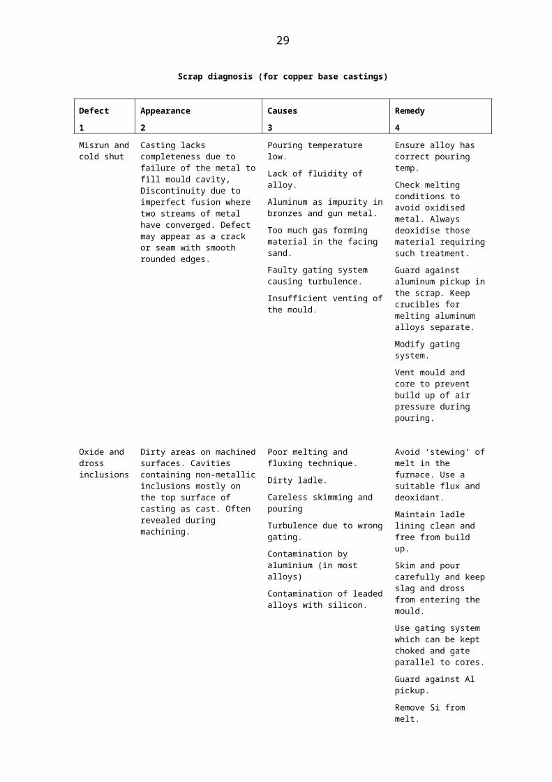
Scrap diagnosis (for copper base castings)
Defect1
Appearance2
Causes3
Remedy4
Misrun and cold shut
Casting lacks completeness due to failure of the metal to fill mould cavity, Discontinuity due to imperfect fusion where two streams of metal have converged. Defect may appear as a crack or seam with smooth rounded edges.
Pouring temperature low.
Lack of fluidity of alloy.
Aluminum as impurity in bronzes and gun metal.
Too much gas forming material in the facing sand.
Faulty gating system causing turbulence.
Insufficient venting of the mould.
Ensure alloy has correct pouring temp.
Check melting conditions to avoid oxidised metal. Always deoxidise those material requiring such treatment.
Guard against aluminum pickup in the scrap. Keep crucibles for melting aluminum alloys separate.
Modify gating system.
Vent mould and core to prevent build up of air pressure during pouring.
Oxide and dross inclusions
Dirty areas on machined surfaces. Cavities containing non-metallic inclusions mostly on the top surface of casting as cast. Often revealed during machining.
Poor melting and fluxing technique.
Dirty ladle.
Careless skimming and pouring
Turbulence due to wrong gating.
Contamination by aluminium (in most alloys)
Contamination of leaded alloys with silicon.
Avoid ‘stewing’ of melt in the furnace. Use a suitable flux and deoxidant.
Maintain ladle lining clean and free from build up.
Skim and pour carefully and keep slag and dross from entering the mould.
Use gating system which can be kept choked and gate parallel to cores.
Guard against Al pickup.
Remove Si from melt.
Fine gas holes (in bronze and gun metal alloys only)
Fine holes distributed throughout whole casting section can be seen in machined surface. More concentrated in areas last to solidify. Risers usually flat or cauliflowered.
Gas taken into solution in alloy when molten and coming out of solution as casting cools.
Dirty or badly corroded scrap.
Damp fluxes.
Highly reducing atmosphere in furnace in case of bronzes and gun
Avoid taking melt to high temperature.
Use correct melting technique.
Apply controlled deoxidation.
Control furnace atmosphere.
Employ inhibiting
24
Defect1
Appearance2
Causes3
Remedy4
metal.
Slight metal mould reaction when casting phosphor bronze alloys.
mould dressing. Note: For those alloys which cannot be degassed by oxidation, deoxidation technique a scavenging treatment is highly successful.
Sub-surface pin holes
Fine porosity just below casting skin revealed on polishing or machining
Metal mould reaction. constituents of molten alloy react with moisture in moulding sand.
Too high a volatile matter content in the facing sand (such as excessive wheat flour)
Mould permeability too low.
Pouring temperature too high for thickness of cast section.
In tin bronze and gun metal keep phosphorus 0.03 per cent. In phosphor bronze keep phosphor content at lower limit of specification.
Avoid flour addition to sand and do not use flour as dusting agent. Use dry sand or a Co2 bonded mould dressed with inhibiting coating.
Increase permeability of sand.
Reduce pouring temperature.
Tin and lead sweat (inverse segregation )
Runners and risers back up. Beads of white metal rich in tin and lead appear on surface of risers and casting.
Gassy metal.
Too high a pouring temp.
High content of Sn and Pb.
Metal mould reaction.
Low permeability of moulding sand.
1. 2. and 4 under gas holes.
3. Reduce content of Sn, Pb, P where possible.
5. Increase permeability of sand
Defective fracture
Fracture shows oxide tints as yellow and brown flakes pronounced dendritic structure indicative of low mechanical properties coarse core like structure indicative of low strength.
Shrinkage, porosity (if localised)
Gassy metal (if general)
Excessive pouring temp. (if structure shows coarse firetree structure).
See remedy under shrinkage cavity.
See remedy under fine gas holes.
Reduce pouring temperature.
Metal penetration (rough surface)
Casting surface rough. Looks as though molten metal has filled voids between sand grains without displacing them.
Lack of suitable mould dressing.
Coarse grained sand.
Loosely rammed sand.
High pouring temperature.
Avoid excessive pouring temperature and check these points.
Ramming technique especially in machine moulding where soft spots are likely to occur.
25
Defect1
Appearance2
Causes3
Remedy4Grading and flowability of sand
Shrinkage cavity
External and internal holes with rough interior. Associated with heavy section and hot spots.
Liquid shrinkage and lack of feed metal.
Incorrect gating of feed.
Faulty design of casting.
Low casting design favours formation of hot spots.
1. 2. Apply suitable running and feeding system.
3. Modify design to create more uniform section.
4. Use correct pouring temperature.
Sand exclusions
Rough holes often containing sand on the top surface of casting as cast. When due to break down of mould lumps corresponding to the cavity defects will be found.
Loose sand in moulding.
Absence of mould dressing.
Sand lacking green of dry bond.
Erosion
Soft ramming.
Overbaked core.
Blow out mould cavity carefully before closing the mould,
Improve hardness of mould surface by coating with suitable dressing.
Increase strength by adding more new sand or clay binder.
Correct gating technique.
Increase ramming density.
Control temperature in drying ovens.
26
Scrap diagnosis (for aluminium alloys castings)
Defect1
Appearance2
Causes3
Remedy4
Pinhole porosity
Small evenly distributed cavities as seen on machine surface. The holes may be round or angular.
H2 gas expelled from solution due to
Moisture in fluxes, refractories and furnace tools. Corrosion products on scrap. Oil contaminated scrap.
Excessive superheating temperature or ‘stewing’ of melt.
Slow melting, encouraging gas pickup from furnace atmosphere.
Apply degassing treatment prior to pouring.
Store fluxes away from dampness. Use preheated crucibles. Preheat and coat furnace tools with refractory dressing.
and 3. Melt quickly and avoid overheating the charge. Do not disturb metal while melting.
Shrinkage cavity
Internal or external holes often with rough walls and evidence of fire tree crystals. Often located at section change. Local hot sots may cause internal spongy areas, sometimes in the form of surface depression known as draw or sink.
Pouring temperature too high causing a high liquid shrinkage and coarse grain structure.
Failure to supply liquid feed metal to areas where shrinkage cavity is forming.
Premature solidification of ingates and risers due to low pouring temperature.
Lack of modification of LM6 alloy
Neglect to encourage directional solidification
Too little residual gas in metal used for gravity die casting.
Lower pouring temp and refine grain.
Use correctly proportioned feeder heads.
Use correct pouring temp. and increase or enlarge ingates and risers.
Modify with sodium addition.
Make use of insulated and exothermic feeding methods. Apply chills. Top pour where possible.
Make controlled additions of gas in the case of gravity die castings.
Misrun and cold shut
Casting not fully formed line or seam of discontinuity. A hole through rounded edge through wall of casting. Lugs, bosses, corners and thin edges not filled out.
Insufficient metal to fill mould.
Incomplete fusion where two streams of metal have converged.
Molten alloy freezes before sand surface has been covered.
Metal sets before mould has been fully filled.
Too much gas forming material in facing sand.
Lack of permeability of sand.
Die too cold or inadequately vented (die casting)
1, 2,3,4 Increase pouring temperature.
2, 6 Increase permeability of sands and venting.
5. Reduce moisture or volatile matter in facing sand.
7. Obvious.
27

Defect1
Appearance2
Causes3
Remedy4
Gas holes (blow holes)
Smooth walled globular holes of varying diameter
Mechanically trapped gas or air from any of the following sources:
Low pouring temperature.
Gases blowing from mould due to low permeability.
Damp fluxes.
Moisture condensed on chills and denseness.
Excessive turbulence during pouring.
Gas involved from core jointing material.
Increase pouring temperature.
Increase permeability of sand and venting.
Use moisture free fluxes.
Warm chills, suitable dressings.
Modify running and gating system to improve smoothness of flow.
Select core adhesives with care.
Unsatisfactory fracture
High silicon LM6 alloy bright crystalline instead of silky cores granular structure indicative of low strength
Lack of modification treatment in Al-Si alloy.
Pouring temp. excessive or too low. Absence of the grain refining elements titanium and boron. Iron content excessive.
Modify by making sodium addition to melt.
Use pyrometric control.
Apply grain refining treatment.
Avoid contamination form iron stirring and plugging tools, laddles, etc. (the harmful effects of iron can be substantially reduced by the addition of Al/Mn hardener to the melt.)
Oxide and dross inclusions
Dirty areas on the machined surfaces. Cavities containing non-metallic inclusions mostly on top surface as cast.
Poor melting and fluxing technique.
Dirty ladle lining.
Careless skimming and pouring.
Turbulence due to badly designed or positioned gates.
Avoid stewing and dross formation during melting.
Keep ladle lining free from skulls and “buildup”.
Skim and pour carefully and keep dross and slag out of mould. Avoid “swirl” of metal in pouring cup.
Use gating system which can be kept choked during running period. Employ dirt traps and do not gate so that metal drives on cores at right angles.
Sand inclusions
Irregular shaped holes containing sand. Mostly located on top “as cast” surface. When due to erosion or scabbing of core or mould, a
Loose sand in the mould.
Lack of bonded strength.
Too soft ramming.
Wrong gating system
Improve the strength of mould surface with a dressing and
Blow out mould and avoid rough handling.
28
Defect1
Appearance2
Causes3
Remedy4
corresponding raised area appears on casting.
allowing erosion of mould surface.
Over baked oil sand cores.
Mill more efficiently and increase binder additions.
Increasing ramming pressure.
Gate parallel to mould and core surfaces.
Reduce stove temperature.
29