catalog 2021 - reaming
TRANSCRIPT


Holem
akin
g
1 Indexable Drilling
2 Indexable Boring
3 Reaming 3
Turn
ing
4 Indexable Turning
5 Parting and Grooving
6 Multifunction
Millin
g
7 Indexable Milling
8 Solid Milling
9 Material examples and article no. index
03|2
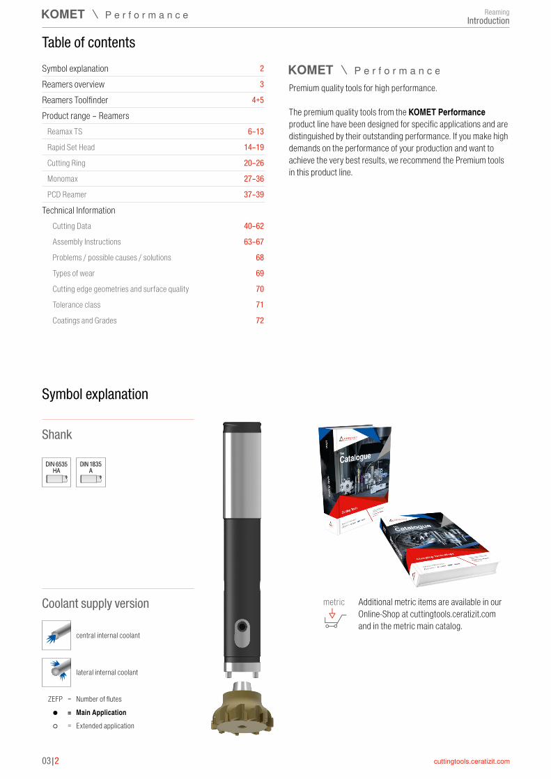
Symbol explanation
Table of contents
Shank
Coolant supply version
central internal coolant
Symbol explanation 2
Reamers overview 3
Reamers Toolfinder 4+5
Product range – ReamersReamax TS 6–13
Rapid Set Head 14–19
Cutting Ring 20–26
Monomax 27–36
PCD Reamer 37–39
Technical InformationCutting Data 40–62
Assembly Instructions 63–67
Problems / possible causes / solutions 68
Types of wear 69
Cutting edge geometries and surface quality 70
Tolerance class 71
Coatings and Grades 72
DIN 6535HA
lateral internal coolant
Premium quality tools for high performance. The premium quality tools from the KOMET Performance product line have been designed for specific applications and are distinguished by their outstanding performance. If you make high demands on the performance of your production and want to achieve the very best results, we recommend the Premium tools in this product line.
Main ApplicationNumber of flutes
Extended application●
ZEFP = =
○ =
DIN 1835A
Additional metric items are available in our Online-Shop at cuttingtools.ceratizit.com and in the metric main catalog.
metric
ReamingIntroduction
3
03|3
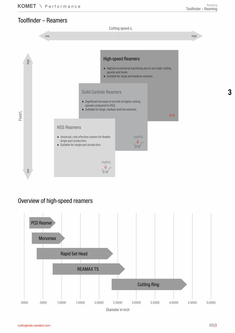
Cutting speed vclow
High-speed Reamers
high
highlow
Feed
f z
Solid Carbide Reamers
HSS Reamers
Overview of high-speed reamers
▲ Highest economical machining due to very high cutting speeds and feeds.
▲ Suitable for large and medium volumes.
▲ Significant increase in tool life at higher cutting speeds compared to HSS.
▲ Suitable for large, medium and low volumes.
▲ Universal, cost effective reamer for flexible single part production.
▲ Suitable for single part production.
Toolfinder – Reamers
metric
metric
4+5
.5000 1.0000 1.5000 2.0000 2.5000 3.0000 3.5000 4.0000 4.5000 5.0000.0000
Monomax
PCD Reamer
Cutting Ring
Rapid Set Head
REAMAX TS
Diameter in inch
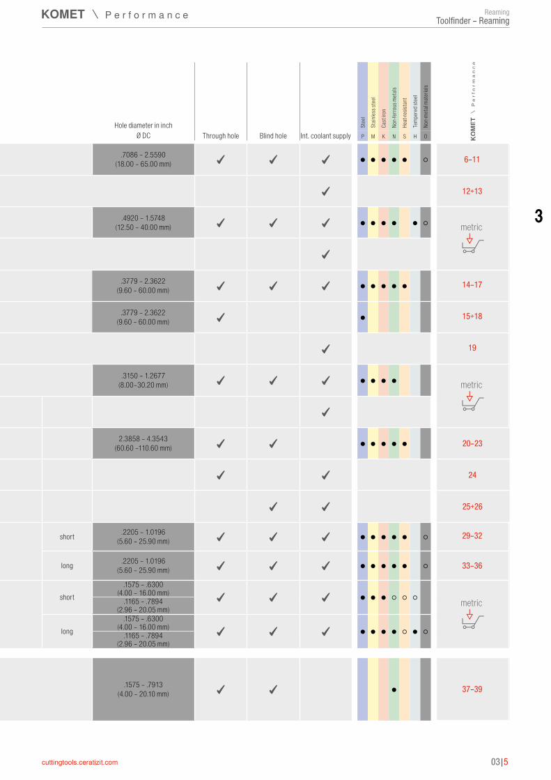
ReamingToolfinder – Reaming
03|4
Toolfinder – Reamers
Hole diameter in inchThrough hole Blind hole Int. coolant supply
Stee
l
Stain
less s
teel
Cast
iron
Non-
ferro
us m
etals
Heat
-resis
tant
Temp
ered
stee
l
Non-
meta
l mat
erial
s
Ø DC P M K N S H O
Solid
carb
ide –
hig
h spe
ed re
amer
s
REAMAX TS
▲ highly flexible and economical replaceable head system ▲ all common materials ▲ can be adjusted in µm range
.7086 – 2.5590(18.00 – 65.00 mm) ✓ ✓ ✓ ● ● ● ● ● ○
▲ Holder available in 3xD and 5xD ▲ DAH zero holder available in 3xD and 5xD ✓
REAMAX
▲ Exchangeable head system, optimized for use with air mist coolant (MMS) ▲ Face and taper contact giving run out accuracy ≤ 2 µm
.4920 – 1.5748(12.50 – 40.00 mm) ✓ ✓ ✓ ● ● ● ● ● ○
▲ holder available in 3xD and 5xD ✓
Rapid Set Head ▲ Exchangeable head system ▲ Left hand spiral fluted cutting blades. available for highest productivity ▲ Re-tipping and regrinding available
.3779 – 2.3622(9.60 – 60.00 mm) ✓ ✓ ✓ ● ● ● ● ●
.3779 – 2.3622(9.60 – 60.00 mm) ✓ ●
✓
MultiChange
▲ flexible quick change system for reaming, countersinking and chamfering ▲ face and taper contact giving run out accuracy ≤ 5 µm
.3150 – 1.2677(8.00–30.20 mm) ✓ ✓ ✓ ● ● ● ●
▲ stable holder in solid carbide and steel, from short to long ✓
Cutting Ring ▲ For large diameter holes. ▲ Compensation for wear through simple readjustment. ▲ Re-tipping and regrinding available
2.3858 – 4.3543(60.60 –110.60 mm) ✓ ✓ ● ● ● ● ●
✓ ✓
✓ ✓
Monomax ▲ Expandable monoblock reamer in 3xD and 5xD ▲ Re-tipping and regrinding available ▲ All common materials
short .2205 – 1.0196(5.60 – 25.90 mm) ✓ ✓ ✓ ● ● ● ● ● ○
long .2205 – 1.0196(5.60 – 25.90 mm) ✓ ✓ ✓ ● ● ● ● ● ○
Fullmax
▲ High-speed reamer in shorter and longer version ▲ Reamers for machining steel, stainless and acid-resistant steels, cast materials,
aluminium and hardened materials up to 63 HRC ▲ Extremely irregular pitch ▲ Standard shank ~ DIN 6535 HA
short.1575 – .6300
(4.00 – 16.00 mm) ✓ ✓ ✓ ● ● ● ○ ○ ○.1165 – .7894 (2.96 – 20.05 mm)
long.1575 – .6300
(4.00 – 16.00 mm) ✓ ✓ ✓ ● ● ● ● ○ ● ○.1165 – .7894 (2.96 – 20.05 mm)
PCD
Ream
er
PCD Reamer ▲ 2 and 4 blade versions available ▲ High stability from the carbide body ▲ Optimized for finishing pre-cast bores ▲ Re-tipping and regrinding available
.1575 – .7913(4.00 – 20.10 mm) ✓ ✓ ●
Solid Carbide Reamers and HSS Reamers can be found in the metric catalog.
ReamingToolfinder – Reaming
3
03|5
Toolfinder – Reamers
Hole diameter in inchThrough hole Blind hole Int. coolant supply
Stee
l
Stain
less s
teel
Cast
iron
Non-
ferro
us m
etals
Heat
-resis
tant
Temp
ered
stee
l
Non-
meta
l mat
erial
s
Ø DC P M K N S H O
Solid
carb
ide –
hig
h spe
ed re
amer
s
REAMAX TS
▲ highly flexible and economical replaceable head system ▲ all common materials ▲ can be adjusted in µm range
.7086 – 2.5590(18.00 – 65.00 mm) ✓ ✓ ✓ ● ● ● ● ● ○
▲ Holder available in 3xD and 5xD ▲ DAH zero holder available in 3xD and 5xD ✓
REAMAX
▲ Exchangeable head system, optimized for use with air mist coolant (MMS) ▲ Face and taper contact giving run out accuracy ≤ 2 µm
.4920 – 1.5748(12.50 – 40.00 mm) ✓ ✓ ✓ ● ● ● ● ● ○
▲ holder available in 3xD and 5xD ✓
Rapid Set Head ▲ Exchangeable head system ▲ Left hand spiral fluted cutting blades. available for highest productivity ▲ Re-tipping and regrinding available
.3779 – 2.3622(9.60 – 60.00 mm) ✓ ✓ ✓ ● ● ● ● ●
.3779 – 2.3622(9.60 – 60.00 mm) ✓ ●
✓
MultiChange
▲ flexible quick change system for reaming, countersinking and chamfering ▲ face and taper contact giving run out accuracy ≤ 5 µm
.3150 – 1.2677(8.00–30.20 mm) ✓ ✓ ✓ ● ● ● ●
▲ stable holder in solid carbide and steel, from short to long ✓
Cutting Ring ▲ For large diameter holes. ▲ Compensation for wear through simple readjustment. ▲ Re-tipping and regrinding available
2.3858 – 4.3543(60.60 –110.60 mm) ✓ ✓ ● ● ● ● ●
✓ ✓
✓ ✓
Monomax ▲ Expandable monoblock reamer in 3xD and 5xD ▲ Re-tipping and regrinding available ▲ All common materials
short .2205 – 1.0196(5.60 – 25.90 mm) ✓ ✓ ✓ ● ● ● ● ● ○
long .2205 – 1.0196(5.60 – 25.90 mm) ✓ ✓ ✓ ● ● ● ● ● ○
Fullmax
▲ High-speed reamer in shorter and longer version ▲ Reamers for machining steel, stainless and acid-resistant steels, cast materials,
aluminium and hardened materials up to 63 HRC ▲ Extremely irregular pitch ▲ Standard shank ~ DIN 6535 HA
short.1575 – .6300
(4.00 – 16.00 mm) ✓ ✓ ✓ ● ● ● ○ ○ ○.1165 – .7894 (2.96 – 20.05 mm)
long.1575 – .6300
(4.00 – 16.00 mm) ✓ ✓ ✓ ● ● ● ● ○ ● ○.1165 – .7894 (2.96 – 20.05 mm)
PCD
Ream
er
PCD Reamer ▲ 2 and 4 blade versions available ▲ High stability from the carbide body ▲ Optimized for finishing pre-cast bores ▲ Re-tipping and regrinding available
.1575 – .7913(4.00 – 20.10 mm) ✓ ✓ ●
6–11
12+13
metric
14–17
15+18
19
metric
20–23
24
25+26
29–32
33–36
metric
37–39
ReamingToolfinder – Reaming

03|6
Material sub-group Index
P
Non alloyed steel
P.1.1P.1.2P.1.3P.1.4P.1.5
Low alloyed steel
P.2.1P.2.2P.2.3P.2.4
High-alloy steel and high-alloy tool steel
P.3.1P.3.2P.3.3
Stainless steelP.4.1P.4.2
M Stainless steelM.1.1M.2.1M.3.1
K
Grey cast ironK.1.1K.1.2
Spherulitic graphite cast ironK.2.1K.2.2
Malleable ironK.3.1K.3.2
N
Aluminum alloys,N.1.1N.1.2
Cast Aluminium AlloysN.2.1N.2.2N.2.3
Copper and copper alloys (Bronze, Brass)
N.3.1N.3.2N.3.3
Magnesium alloys N.4.1
S
Heat resistant alloys
S.1.1S.1.2S.2.1S.2.2S.2.3
Titanium alloysS.3.1S.3.2S.3.3
O Non-metal materials
O.1.1O.1.2O.2.1O.2.2O.3.1
Ø .7086 – 2.5590 inchKOMET no. 75J.65 75J.65 75J.17 75J.71 75J.71 75J.71 75J.93 75J.93 75J.21
Grind geometry ASG3000 ASG0106 ASG0706 ASG3000 ASG4000 ASG0106 ASG4000 ASG3000 ASG03Lead angle 45° 45° 45°/8° 45° 25° 45° 25° 45° 30°/2°
Grade / coating DBG-P DBG-P DBC TiN TiN TiN DST DST K10Article no. 49 586 49 521 49 526 49 534 49 596 49 520 49 597 49 544 49 531
ApplicationThrough hole
● ○ ● ● ●
● ○ ● ●
● ○
● ○
● ○
● ● ●
● ●●
●
● ○
●
●
○
REAMAX TS – Selection guide – Through hole
Applications: Main application ●Additional range of application ○
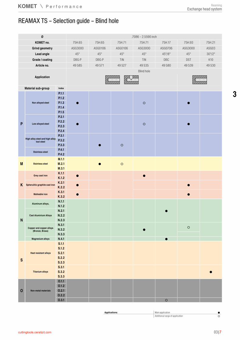
ReamingExchange head system
3
03|7
Ø .7086 – 2.5590 inchKOMET no. 75H.65 75H.65 75H.71 75H.71 75H.17 75H.93 75H.21
Grind geometry ASG3000 ASG0106 ASG0106 ASG3000 ASG0706 ASG3000 ASG03Lead angle 45° 45° 45° 45° 45°/8° 45° 30°/2°
Grade / coating DBG-P DBG-P TiN TiN DBC DST K10Article no. 49 585 49 571 49 527 49 535 49 580 49 539 49 530
ApplicationBlind hole
REAMAX TS – Selection guide – Blind hole
Applications: Main application ●Additional range of application ○
Material sub-group Index
P
Non alloyed steel
P.1.1P.1.2P.1.3P.1.4P.1.5
Low alloyed steel
P.2.1P.2.2P.2.3P.2.4
High-alloy steel and high-alloy tool steel
P.3.1P.3.2P.3.3
Stainless steelP.4.1P.4.2
M Stainless steelM.1.1M.2.1M.3.1
K
Grey cast ironK.1.1K.1.2
Spherulitic graphite cast ironK.2.1K.2.2
Malleable ironK.3.1K.3.2
N
Aluminum alloys,N.1.1N.1.2
Cast Aluminium AlloysN.2.1N.2.2N.2.3
Copper and copper alloys (Bronze, Brass)
N.3.1N.3.2N.3.3
Magnesium alloys N.4.1
S
Heat resistant alloys
S.1.1S.1.2S.2.1S.2.2S.2.3
Titanium alloysS.3.1S.3.2S.3.3
O Non-metal materials
O.1.1O.1.2O.2.1O.2.2O.3.1
● ○ ●
● ○ ●
● ○
● ○
● ●
● ●
● ●
●
● ○
●
●
○
ReamingExchange head system

03|8
REAMAX TS – Replaceable reaming heads ▲ up to tolerance class IT 6 ▲ precise repeatability < .0001" ▲ high precision grind for maximum quality ▲ can be adjusted for the smallest hole tolerances
▲ interface enables head change in the machine ▲ retraction from the hole at 3–4 times the cutting feed rate ▲ KLG = coupling size ▲ ZEFP = number of cutting edges
KLG
LPR
L
DC
DST DBG-P DBC DST
75J.93 75J.65 75J.17 75J.93 25° 45° 45/8° 45°
ASG4000 ASG0106 ASG0706 ASG3000CERMET HM HM CERMET
Through hole Through hole Through hole Through hole
49 597 ... 49 521 ... 49 526 ... 49 544 ...DC L LPR ZEFP KLG
inch inch inch 0.7087 - 0.7874 0.236 0.787 6 1 xxxxxxxxx 1) xxxxxxxxx 1) xxxxxxxxx 1) xxxxxxxxx 1)
0.7874 - 0.8661 0.236 0.787 6 2 xxxxxxxxx 1) xxxxxxxxx 1) xxxxxxxxx 1) xxxxxxxxx 1)
0.8661 - 1.0630 0.236 0.787 6 3 xxxxxxxxx 1) xxxxxxxxx 1) xxxxxxxxx 1) xxxxxxxxx 1)
1.0630 - 1.2519 0.236 0.984 6 4 xxxxxxxxx 1) xxxxxxxxx 1) xxxxxxxxx 1) xxxxxxxxx 1)
1.2520 - 1.3779 0.236 0.984 8 4 xxxxxxxxx 1) xxxxxxxxx 1) xxxxxxxxx 1) xxxxxxxxx 1)
1.3780 - 1.6535 0.236 0.984 8 5 xxxxxxxxx 1) xxxxxxxxx 1) xxxxxxxxx 1) xxxxxxxxx 1)
1.6535 - 2.0472 0.236 1.181 8 6 xxxxxxxxx 1) xxxxxxxxx 1) xxxxxxxxx 1) xxxxxxxxx 1)
2.0472 - 2.5590 0.314 1.377 10 7 xxxxxxxxx 1) xxxxxxxxx 1) xxxxxxxxx 1) xxxxxxxxx 1)
P ● ● ●M ● K ● ●N ● ○S H O ○
1) Not available from stock, articles are non-returnable and cannot be exchanged / Minimum order 2 pieces → vc Page 41–44
For xxxx please indicate piece part bore diameter and tolerance. (e.g. Ø 1.5000" ±.0005")
Assembly instructions can be found on → Page 63+64
ReamingExchange head system

3
03|9
REAMAX TS – Replaceable reaming heads ▲ up to tolerance class IT 6 ▲ precise repeatability < .0001" ▲ high precision grind for maximum quality ▲ can be adjusted for the smallest hole tolerances
▲ interface enables head change in the machine ▲ retraction from the hole at 3–4 times the cutting feed rate ▲ KLG = coupling size ▲ ZEFP = number of cutting edges
KLG
LPR
L
DC
TiN DBG-P K10 TiN TiN
75J.71 75J.65 75J.21 75J.71 75J.71 25° 45° 30/2° 45° 45°
ASG4000 ASG3000 ASG03 ASG0106 ASG3000HM HM HM HM HM
Through hole Through hole Through hole Through hole Through hole
49 596 ... 49 586 ... 49 531 ... 49 520 ... 49 534 ...DC L LPR ZEFP KLG
inch inch inch 0.7087 - 0.7874 0.236 0.787 6 1 xxxxxxxxx 1) xxxxxxxxx 1) xxxxxxxxx 1) xxxxxxxxx 1) xxxxxxxxx 1)
0.7874 - 0.8661 0.236 0.787 6 2 xxxxxxxxx 1) xxxxxxxxx 1) xxxxxxxxx 1) xxxxxxxxx 1) xxxxxxxxx 1)
0.8661 - 1.0630 0.236 0.787 6 3 xxxxxxxxx 1) xxxxxxxxx 1) xxxxxxxxx 1) xxxxxxxxx 1) xxxxxxxxx 1)
1.0630 - 1.2519 0.236 0.984 6 4 xxxxxxxxx 1) xxxxxxxxx 1) xxxxxxxxx 1) xxxxxxxxx 1) xxxxxxxxx 1)
1.252 0- 1.3779 0.236 0.984 8 4 xxxxxxxxx 1) xxxxxxxxx 1) xxxxxxxxx 1) xxxxxxxxx 1) xxxxxxxxx 1)
1.3780 - 1.6535 0.236 0.984 8 5 xxxxxxxxx 1) xxxxxxxxx 1) xxxxxxxxx 1) xxxxxxxxx 1) xxxxxxxxx 1)
1.6535 - 2.0472 0.236 1.181 8 6 xxxxxxxxx 1) xxxxxxxxx 1) xxxxxxxxx 1) xxxxxxxxx 1) xxxxxxxxx 1)
2.0472 - 2.5590 0.314 1.377 10 7 xxxxxxxxx 1) xxxxxxxxx 1) xxxxxxxxx 1) xxxxxxxxx 1) xxxxxxxxx 1)
P ● ● ○ ○M ○ K ● ○N ●S ● H O
1) Not available from stock, articles are non-returnable and cannot be exchanged / Minimum order 2 pieces → vc Page 41–44
For xxxx please indicate piece part bore diameter and tolerance. (e.g. Ø 1.5000" ±.0005")
Assembly instructions can be found on → Page 63+64
ReamingExchange head system

03|10
REAMAX TS – Replaceable reaming heads ▲ up to tolerance class IT 6 ▲ precise repeatability < .0001" ▲ high precision grind for maximum quality ▲ can be adjusted for the smallest hole tolerances
▲ interface enables head change in the machine ▲ retraction from the hole at 3–4 times the cutting feed rate ▲ KLG = coupling size ▲ ZEFP = number of cutting edges
KLG
LPR
L
DC
DST DBG-P DBC DBG-P TiN
75H.93 75H.65 75H.17 75H.65 75H.71 45° 45° 45/8° 45° 45°
ASG3000 ASG0106 ASG0706 ASG3000 ASG3000CERMET HM HM HM HM
Blind hole Blind hole Blind hole Blind hole Blind hole
49 539 ... 49 571 ... 49 580 ... 49 585 ... 49 535 ...DC L LPR ZEFP KLG
inch inch inch 0.7087 - 0.7874 0.236 0.787 6 1 xxxxxxxxx 1) xxxxxxxxx 1) xxxxxxxxx 1) xxxxxxxxx 1) xxxxxxxxx 1)
0.7874 - 0.8661 0.236 0.787 6 2 xxxxxxxxx 1) xxxxxxxxx 1) xxxxxxxxx 1) xxxxxxxxx 1) xxxxxxxxx 1)
0.8661 - 1.0630 0.236 0.787 6 3 xxxxxxxxx 1) xxxxxxxxx 1) xxxxxxxxx 1) xxxxxxxxx 1) xxxxxxxxx 1)
1.0630 - 1.2519 0.236 0.984 6 4 xxxxxxxxx 1) xxxxxxxxx 1) xxxxxxxxx 1) xxxxxxxxx 1) xxxxxxxxx 1)
1.2520 - 1.3779 0.236 0.984 8 4 xxxxxxxxx 1) xxxxxxxxx 1) xxxxxxxxx 1) xxxxxxxxx 1) xxxxxxxxx 1)
1.3780 - 1.6535 0.236 0.984 8 5 xxxxxxxxx 1) xxxxxxxxx 1) xxxxxxxxx 1) xxxxxxxxx 1) xxxxxxxxx 1)
1.6535 - 2.0472 0.236 1.181 8 6 xxxxxxxxx 1) xxxxxxxxx 1) xxxxxxxxx 1) xxxxxxxxx 1) xxxxxxxxx 1)
2.0472 - 2.5590 0.314 1.377 10 7 xxxxxxxxx 1) xxxxxxxxx 1) xxxxxxxxx 1) xxxxxxxxx 1) xxxxxxxxx 1)
P ● ● ● ○M ● K ● ● ○N ○ ● ●S H O ○
1) Not available from stock, articles are non-returnable and cannot be exchanged / Minimum order 2 pieces → vc Page 41–44
For xxxx please indicate piece part bore diameter and tolerance. (e.g. Ø 1.5000" ±.0005")
Assembly instructions can be found on → Page 63+64
ReamingExchange head system

3
03|11
REAMAX TS – Replaceable reaming heads ▲ up to tolerance class IT 6 ▲ precise repeatability < .0001" ▲ high precision grind for maximum quality ▲ can be adjusted for the smallest hole tolerances
▲ interface enables head change in the machine ▲ retraction from the hole at 3–4 times the cutting feed rate ▲ KLG = coupling size ▲ ZEFP = number of cutting edges
KLG
LPR
L
DC
K10 TiN
75H.21 75H.71 30/2° 45°ASG03 ASG0106
HM HMBlind hole Blind hole
49 530 ... 49 527 ...DC L LPR ZEFP KLG
inch inch inch 0.7087 - 0.7874 0.236 0.787 6 1 xxxxxxxxx 1) xxxxxxxxx 1)
0.7874 - 0.8661 0.236 0.787 6 2 xxxxxxxxx 1) xxxxxxxxx 1)
0.8661 - 1.0630 0.236 0.787 6 3 xxxxxxxxx 1) xxxxxxxxx 1)
1.0630 - 1.2519 0.236 0.984 6 4 xxxxxxxxx 1) xxxxxxxxx 1)
1.2520 - 1.3779 0.236 0.984 8 4 xxxxxxxxx 1) xxxxxxxxx 1)
1.3780 - 1.6535 0.236 0.984 8 5 xxxxxxxxx 1) xxxxxxxxx 1)
1.6535 - 2.0472 0.236 1.181 8 6 xxxxxxxxx 1) xxxxxxxxx 1)
2.0472 - 2.5590 0.314 1.377 10 7 xxxxxxxxx 1) xxxxxxxxx 1)
P ○M ○K N S ● H O
1) Not available from stock, articles are non-returnable and cannot be exchanged / Minimum order 2 pieces → vc Page 41–44
For xxxx please indicate piece part bore diameter and tolerance. (e.g. Ø 1.5000" ±.0005")
Assembly instructions can be found on → Page 63+64
ReamingExchange head system

03|12
Do not heat shrink tools !
Clamping key – T Screwdriver Reamax TS pull stud
80 397 ... 80 950 ... 40 900 ...Spare parts DC 0.7087 - 0.7870 T08 - IP 80950039 40900001000.7874 - 0.8657 SW2,5 80397025 40900002000.8661 - 1.0626 SW3 80397030 40900003001.0630 - 1.3776 SW3 80397030 40900004001.3780 - 1.6535 SW3 80397030 40900005001.6535 - 2.0472 SW4 80397040 40900005002.0472 - 2.5590 SW5 80397050 4090000700
Assembly instructions can be found on → Page 63+64
REAMAX TS – Holder ▲ KLG = Coupling Size
Supply details:Complete holder with pull stud. Reamer head not included
~A ~A≤ 3xD ≤ 5xD
40 501 ... 40 503 ...DC KOMET no. OAL l2 LPR L DCONMS DCONMS M KLG
inch inch inch inch inch inch mm Nm 0.7087 - 0.7870 75A.40.13010 5.118 0.787 3.149 0.236 0.787 20 1,5 1 40501020990.7087 - 0.7870 75A.40.15010 7.480 0.787 5.511 0.236 0.787 20 1,5 1 40503020990.7874 - 0.8657 75A.40.13020 5.118 0.787 3.149 0.236 0.787 20 2,5 2 40501022990.7874 - 0.8657 75A.40.15020 7.480 0.787 5.511 0.236 0.787 20 2,5 2 40503022990.8661 - 1.0626 75A.40.13030 5.118 0.787 3.149 0.236 0.787 20 4 3 40501027990.8661 - 1.0626 75A.40.15030 8.267 0.787 6.299 0.236 0.787 20 4 3 40503027991.0630 - 1.3776 75A.40.13040 6.929 0.984 4.724 0.236 0.984 25 5 4 40501035991.0630 - 1.3776 75A.40.15040 9.291 0.984 7.086 0.236 0.984 25 5 4 40503035991.3780 - 1.6535 75A.40.13050 6.929 0.984 4.724 0.236 0.984 25 6 5 40501042991.3780 - 1.6535 75A.40.15050 10.078 0.984 7.874 0.236 0.984 25 6 5 40503042991.6535 - 2.0472 75A.40.13060 7.086 1.181 4.724 0.236 1.259 32 10 6 40501052991.6535 - 2.0472 75A.40.15060 11.023 1.181 8.661 0.236 1.259 32 10 6 40503052992.0472 - 2.5590 75A.40.13070 7.086 1.181 4.724 0.314 1.259 32 13 7 40501065992.0472 - 2.5590 75A.40.15070 11.023 1.181 8.661 0.314 1.259 32 13 7 4050306599
ReamingExchange head system

3
03|13
Do not heat shrink tools !
Clamping key – T Screwdriver Reamax TS pull stud
80 397 ... 80 950 ... 40 900 ...Spare parts DC 0.7087 - 0.7870 T08 - IP 80950039 40900001000.7874 - 0.8657 SW2,5 80397025 40900002000.8661 - 1.0626 SW3 80397030 40900003001.0630 - 1.3776 SW3 80397030 40900004001.3780 - 1.6535 SW3 80397030 4090000500
Assembly instructions can be found on → Page 63+64
REAMAX TS – Holder ▲ KLG = Coupling size ▲ Adjustment inside the machine ▲ Alignable DAH Zero holder for correction of concentricity error ▲ DAH Zero holder is pre-loaded and set to a runout of < 0.0002"
Supply details:Complete holder with pull stud. Reamer head not included
DAH Zero
DAH Zero
~A ~A≤ 3xD ≤ 5xD
40 504 ... 40 506 ...DC KOMET no. OAL l2 LPR L DCONMS DCONMS M KLG
inch inch inch inch inch inch mm Nm 0.7087 - 0.7870 75A.41.13010 5.708 0.787 3.149 0.236 0.787 20 1,5 1 40504020990.7087 - 0.7870 75A.41.15010 8.070 0.787 5.511 0.236 0.787 20 1,5 1 40506020990.7874 - 0.8657 75A.41.13020 5.708 0.787 3.149 0.236 0.787 20 2,5 2 40504022990.7874 - 0.8657 75A.41.15020 8.070 0.787 5.511 0.236 0.787 20 2,5 2 40506022990.8661 - 1.0626 75A.41.13030 5.708 0.787 3.149 0.236 0.787 20 4 3 40504027990.8661 - 1.0626 75A.41.15030 8.858 0.787 6.299 0.236 0.787 20 4 3 40506027991.0630 - 1.3776 75A.41.13040 5.708 0.984 4.724 0.236 0.984 25 5 4 40504035991.0630 - 1.3776 75A.41.15040 9.291 0.984 7.086 0.236 0.984 25 5 4 40506035991.3780 - 1.6535 75A.41.13050 6.929 0.984 4.724 0.236 0.984 25 6 5 40504042991.3780 - 1.6535 75A.41.15050 9.291 0.984 7.874 0.236 0.984 25 6 5 4050604299
ReamingExchange head system
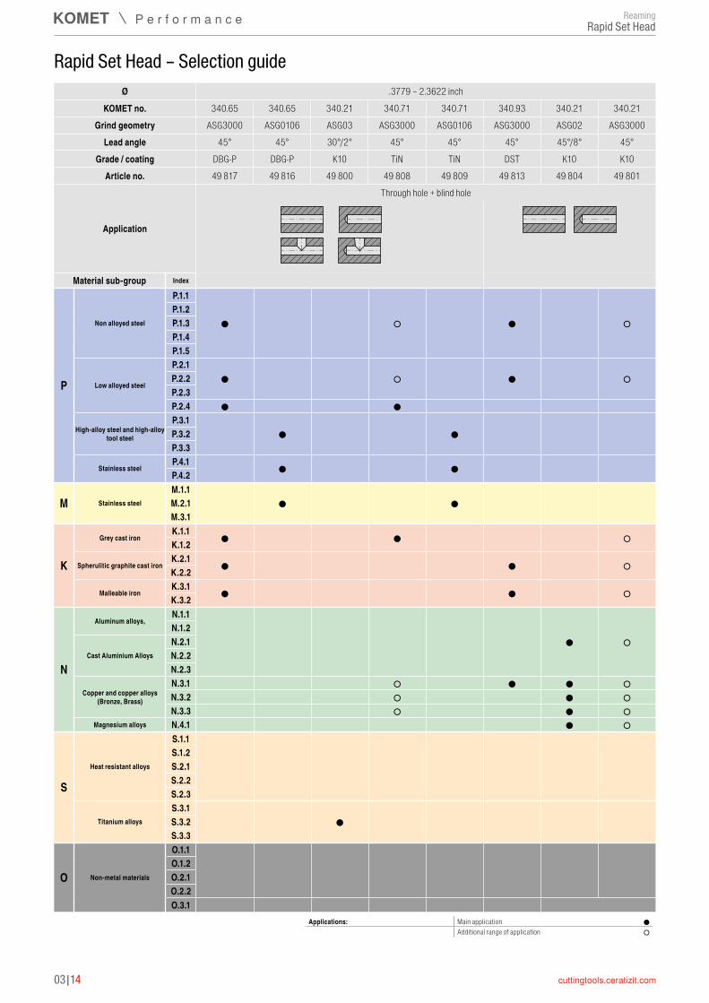
03|14
Rapid Set Head – Selection guide
Applications: Main application ●Additional range of application ○
Material sub-group Index
P
Non alloyed steel
P.1.1P.1.2P.1.3P.1.4P.1.5
Low alloyed steel
P.2.1P.2.2P.2.3P.2.4
High-alloy steel and high-alloy tool steel
P.3.1P.3.2P.3.3
Stainless steelP.4.1P.4.2
M Stainless steelM.1.1M.2.1M.3.1
K
Grey cast ironK.1.1K.1.2
Spherulitic graphite cast ironK.2.1K.2.2
Malleable ironK.3.1K.3.2
N
Aluminum alloys,N.1.1N.1.2
Cast Aluminium AlloysN.2.1N.2.2N.2.3
Copper and copper alloys (Bronze, Brass)
N.3.1N.3.2N.3.3
Magnesium alloys N.4.1
S
Heat resistant alloys
S.1.1S.1.2S.2.1S.2.2S.2.3
Titanium alloysS.3.1S.3.2S.3.3
O Non-metal materials
O.1.1O.1.2O.2.1O.2.2O.3.1
Ø .3779 – 2.3622 inchKOMET no. 340.65 340.65 340.21 340.71 340.71 340.93 340.21 340.21
Grind geometry ASG3000 ASG0106 ASG03 ASG3000 ASG0106 ASG3000 ASG02 ASG3000Lead angle 45° 45° 30°/2° 45° 45° 45° 45°/8° 45°
Grade / coating DBG-P DBG-P K10 TiN TiN DST K10 K10Article no. 49 817 49 816 49 800 49 808 49 809 49 813 49 804 49 801
Application
Through hole + blind hole
● ○ ● ○
● ○ ● ○
● ●
● ●
● ●
● ●
● ● ○
● ● ○
● ● ○
● ○
○ ● ● ○○ ● ○○ ● ○
● ○
●
ReamingRapid Set Head
3
03|15
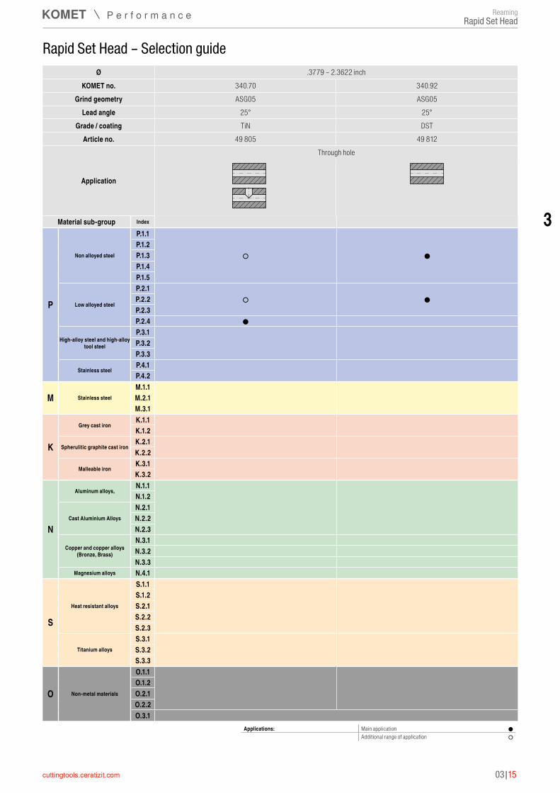
Rapid Set Head – Selection guide
Applications: Main application ●Additional range of application ○
Material sub-group Index
P
Non alloyed steel
P.1.1P.1.2P.1.3P.1.4P.1.5
Low alloyed steel
P.2.1P.2.2P.2.3P.2.4
High-alloy steel and high-alloy tool steel
P.3.1P.3.2P.3.3
Stainless steelP.4.1P.4.2
M Stainless steelM.1.1M.2.1M.3.1
K
Grey cast ironK.1.1K.1.2
Spherulitic graphite cast ironK.2.1K.2.2
Malleable ironK.3.1K.3.2
N
Aluminum alloys,N.1.1N.1.2
Cast Aluminium AlloysN.2.1N.2.2N.2.3
Copper and copper alloys (Bronze, Brass)
N.3.1N.3.2N.3.3
Magnesium alloys N.4.1
S
Heat resistant alloys
S.1.1S.1.2S.2.1S.2.2S.2.3
Titanium alloysS.3.1S.3.2S.3.3
O Non-metal materials
O.1.1O.1.2O.2.1O.2.2O.3.1
Ø .3779 – 2.3622 inchKOMET no. 340.70 340.92
Grind geometry ASG05 ASG05Lead angle 25° 25°
Grade / coating TiN DSTArticle no. 49 805 49 812
Application
Through hole
○ ●
○ ●
●
ReamingRapid Set Head

03|16
Rapid Set Head ▲ PHD = Approximate diameter for face machining geometries (ASG) ▲ KLG = Coupling Size ▲ ZEFP = Number of cutting edges
DC
L LPR
PHD
KLG
TiN TiN K10 K10 K10
340.71 340.71 340.21 340.21 340.21 45° 45° 45° 30/2° 45/8°
ASG3000 ASG0106 ASG3000 ASG03 ASG02HM HM HM HM HM
Through hole + blind hole
Through hole + blind hole
Through hole + blind hole
Through hole + blind hole
Through hole + blind hole
49 808 ... 49 809 ... 49 801 ... 49 800 ... 49 804 ...DC L LPR ZEFP PHD KLG
inch inch inch inch 0.378 - 0.4957 0.374 0.433 4 DC-0.1220 1 xxxxxxxxx 1) xxxxxxxxx 1) xxxxxxxxx 1) xxxxxxxxx 1) xxxxxxxxx 1)
0.4961 - 0.6138 0.413 0.433 4 DC-0.1417 2 xxxxxxxxx 1) xxxxxxxxx 1) xxxxxxxxx 1) xxxxxxxxx 1) xxxxxxxxx 1)
0.6142 - 0.7319 0.413 0.433 6 DC-0.1417 3 xxxxxxxxx 1) xxxxxxxxx 1) xxxxxxxxx 1) xxxxxxxxx 1) xxxxxxxxx 1)
0.7323 - 0.9449 0.413 0.433 6 DC-0.2008 4 xxxxxxxxx 1) xxxxxxxxx 1) xxxxxxxxx 1) xxxxxxxxx 1) xxxxxxxxx 1)
0.9453 - 1.185 0.413 0.433 6 DC-0.2362 5 xxxxxxxxx 1) xxxxxxxxx 1) xxxxxxxxx 1) xxxxxxxxx 1) xxxxxxxxx 1)
1.1854 - 1.2165 0.629 0.669 6 DC-0.2953 6 xxxxxxxxx 1) xxxxxxxxx 1) xxxxxxxxx 1) xxxxxxxxx 1) xxxxxxxxx 1)
1.2169 - 1.5748 0.629 0.669 6 DC-0.2953 6 xxxxxxxxx 1) xxxxxxxxx 1) xxxxxxxxx 1) xxxxxxxxx 1) xxxxxxxxx 1)
1.5752 - 1.9957 0.629 0.669 6 DC-0.3150 7 xxxxxxxxx 1) xxxxxxxxx 1) xxxxxxxxx 1) xxxxxxxxx 1) xxxxxxxxx 1)
1.9961 - 2.3622 0.629 0.669 6 DC-0.3150 8 xxxxxxxxx 1) xxxxxxxxx 1) xxxxxxxxx 1) xxxxxxxxx 1) xxxxxxxxx 1)
P ○ ○ ○ M ○ K ○ ○ N ○ ○ ●S ● H O
1) Not available from stock, articles are non-returnable and cannot be exchanged / Minimum order 2 pieces → vc Page 57–61
For xxxx please indicate piece part bore diameter and tolerance. (e.g. Ø 1.5000" ±.0005")
Assembly instructions can be found on → Page 65
ReamingRapid Set Head

3
03|17
Rapid Set Head ▲ PHD = Approximate diameter for face machining geometries (ASG) ▲ KLG = Coupling Size ▲ ZEFP = Number of cutting edges
DC
L LPR
PHD
KLG
DST DBG-P DBG-P
340.93 340.65 340.65 45° 45° 45°
ASG3000 ASG3000 ASG0106CERMET HM HM
Through hole + blind hole
Through hole + blind hole
Through hole + blind hole
49 813 ... 49 817 ... 49 816 ...DC L LPR PHD KLG ZEFP
inch inch inch inch 0.378 - 0.4957 0.374 0.433 DC-0.1220 1 4 xxxxxxxxx 1) xxxxxxxxx 1) xxxxxxxxx 1)
0.4961 - 0.6138 0.413 0.433 DC-0.1417 2 4 xxxxxxxxx 1) xxxxxxxxx 1) xxxxxxxxx 1)
0.6142 - 0.7319 0.413 0.433 DC-0.1417 4 6 xxxxxxxxx 1) xxxxxxxxx 1)
0.6142 - 0.7319 0.413 0.433 DC-0.1417 3 6 xxxxxxxxx 1)
0.7323 - 0.9449 0.413 0.433 DC-0.2008 4 6 xxxxxxxxx 1) xxxxxxxxx 1) xxxxxxxxx 1)
0.9453 - 1.185 0.413 0.433 DC-0.2362 5 6 xxxxxxxxx 1) xxxxxxxxx 1) xxxxxxxxx 1)
1.1854 - 1.2165 0.629 0.669 DC-0.2953 6 6 xxxxxxxxx 1) xxxxxxxxx 1) xxxxxxxxx 1)
1.2169 - 1.5748 0.629 0.669 DC-0.2953 6 6 xxxxxxxxx 1) xxxxxxxxx 1) xxxxxxxxx 1)
1.5752 - 1.9957 0.629 0.669 DC-0.3150 7 6 xxxxxxxxx 1) xxxxxxxxx 1) xxxxxxxxx 1)
1.9961 - 2.3622 0.629 0.669 DC-0.3150 8 6 xxxxxxxxx 1) xxxxxxxxx 1) xxxxxxxxx 1)
P ● ● ●M ●K ● ● N ● S H O
1) Not available from stock, articles are non-returnable and cannot be exchanged / Minimum order 2 pieces → vc Page 57–61
For xxxx please indicate piece part bore diameter and tolerance. (e.g. Ø 1.5000" ±.0005")
Assembly instructions can be found on → Page 65
ReamingRapid Set Head

03|18
Rapid Set Head ▲ KLG = Coupling Size ▲ ZEFP = Number of cutting edges
DC
KLG
L LPR
TiN DST
340.70 340.92 25° 25°ASG05 ASG05
HM CERMETThrough hole Through hole
49 805 ... 49 812 ...DC L LPR KLG ZEFP
inch inch inch 0.378 - 0.4957 0.374 0.433 1 4 xxxxxxxxx 1) xxxxxxxxx 1)
0.4961 - 0.6138 0.413 0.433 2 4 xxxxxxxxx 1) xxxxxxxxx 1)
0.6142 - 0.7319 0.413 0.433 3 4 xxxxxxxxx 1) xxxxxxxxx 1)
0.7323 - 0.9449 0.413 0.433 4 6 xxxxxxxxx 1) xxxxxxxxx 1)
0.9453 - 1.185 0.413 0.433 5 6 xxxxxxxxx 1) xxxxxxxxx 1)
1.1854 - 1.2165 0.629 0.669 6 6 xxxxxxxxx 1) xxxxxxxxx 1)
1.2169 - 1.5748 0.629 0.669 6 6 xxxxxxxxx 1) xxxxxxxxx 1)
1.5752 - 1.9957 0.629 0.669 7 6 xxxxxxxxx 1) xxxxxxxxx 1)
1.9961 - 2.3622 0.629 0.669 8 6 xxxxxxxxx 1) xxxxxxxxx 1)
P ○ ●M K N S H O
1) Not available from stock, articles are non-returnable and cannot be exchanged / Minimum order 2 pieces → vc Page 57–61
For xxxx please indicate piece part bore diameter and tolerance. (e.g. Ø 1.5000" ±.0005")
Assembly instructions can be found on → Page 65
ReamingRapid Set Head
3
03|19
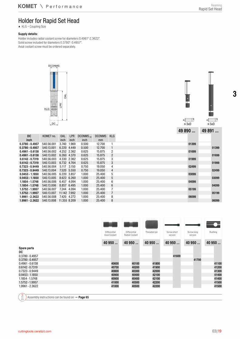
Holder for Rapid Set Head ▲ KLG = Coupling Size
Supply details:Holder includes radial coolant screw for diameters 0.4961"-2.3622". Solid screw included for diameters 0.3780"- 0.4957". Axial coolant screw must be ordered separately.
DCONMSO
AL
LPR
DC
KLG
A A≤ 3xD ≤ 5xD
49 890 ... 49 891 ...DC KOMET no. OAL LPR DCONMS h6 DCONMS KLG
inch inch inch inch mm0.3780 - 0.4957 540.56.001 3.740 1.969 0.500 12.700 1 49890013990.3780 - 0.4957 540.13.001 6.220 4.449 0.500 12.700 1 49891013990.4961 - 0.6138 540.56.002 4.252 2.362 0.625 15.875 2 49890016990.4961 - 0.6138 540.13.002 6.260 4.370 0.625 15.875 2 49891016990.6142 - 0.7319 540.56.003 4.330 2.362 0.625 15.875 3 49890019990.6142 - 0.7319 540.13.003 6.732 4.764 0.625 15.875 3 49891019990.7323 - 0.9449 540.56.004 5.117 3.150 0.750 19.050 4 49890024990.7323 - 0.9449 540.13.004 7.520 5.550 0.750 19.050 4 49891024990.9453 - 1.1850 540.56.005 6.220 3.857 1.000 25.400 5 49890030990.9453 - 1.1850 540.13.005 8.622 6.260 1.000 25.400 5 49891030991.1854 - 1.5748 540.56.006 6.457 4.094 1.000 25.400 6 49890040991.1854 - 1.5748 540.13.006 8.857 6.495 1.000 25.400 6 49891040991.5752 - 1.9957 540.56.007 7.244 4.094 1.000 25.400 7 49890051991.5752 - 1.9957 540.13.007 11.142 7.992 1.000 25.400 7 49891051991.9961 - 2.3622 540.56.008 7.420 4.272 1.000 25.400 8 49890060991.9961 - 2.3622 540.13.008 11.355 8.209 1.000 25.400 8 4989106099
Differential Axial Coolant
Differential Radial Coolant
Threaded pin Screw short version
Screw long version
Bushing
40 950 ... 40 950 ... 40 950 ... 40 950 ... 40 950 ... 40 950 ...Spare partsDC 0.3780 - 0.4957 40950416000.3780 - 0.4957 40950417000.4961 - 0.6138 4095040600 4095040100 4095041800 40950411000.6142 - 0.7319 4095040700 4095040200 4095041900 40950412000.7323 - 0.9449 4095040800 4095040300 4095042000 40950413000.9453 - 1.1850 4095040900 4095040400 4095042100 40950414001.1854 - 1.5748 4095040900 4095040400 4095042100 40950414001.5752 - 1.9957 4095041000 4095040500 4095042200 40950415001.9961 - 2.3622 4095041000 4095040500 4095042200 4095041500
Assembly instructions can be found on → Page 65
ReamingRapid Set Head
03|20
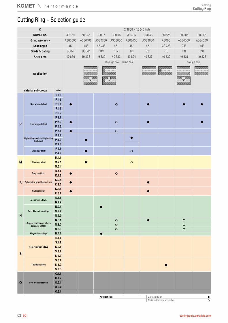
Cutting Ring – Selection guide
Material sub-group Index
P
Non alloyed steel
P.1.1P.1.2P.1.3P.1.4P.1.5
Low alloyed steel
P.2.1P.2.2P.2.3P.2.4
High-alloy steel and high-alloy tool steel
P.3.1P.3.2P.3.3
Stainless steelP.4.1P.4.2
M Stainless steelM.1.1M.2.1M.3.1
K
Grey cast ironK.1.1K.1.2
Spherulitic graphite cast ironK.2.1K.2.2
Malleable ironK.3.1K.3.2
N
Aluminum alloys,N.1.1N.1.2
Cast Aluminium AlloysN.2.1N.2.2N.2.3
Copper and copper alloys (Bronze, Brass)
N.3.1N.3.2N.3.3
Magnesium alloys N.4.1
S
Heat resistant alloys
S.1.1S.1.2S.2.1S.2.2S.2.3
Titanium alloysS.3.1S.3.2S.3.3
O Non-metal materials
O.1.1O.1.2O.2.1O.2.2O.3.1
Ø 2.3858 – 4.3543 inchKOMET no. 300.65 300.65 300.17 300.05 300.05 300.45 300.25 300.05 300.45
Grind geometry ASG3000 ASG0106 ASG0706 ASG3000 ASG0106 ASG3000 ASG03 ASG4000 ASG4000Lead angle 45° 45° 45°/8° 45° 45° 45° 30°/2° 25° 45°
Grade / coating DBG-P DBG-P DBC TiN TiN DST K10 TiN DSTArticle no. 49 836 49 835 49 839 49 823 49 824 49 827 49 832 49 831 49 828
Application
Through hole + blind hole Through hole
● ○ ● ● ●
● ○ ● ●
● ○
● ●
● ○
● ○
● ○
● ●
● ●
●
○ ● ○○ ○○ ○
●
●
Applications: Main application ●Additional range of application ○
ReamingCutting Ring

3
03|21
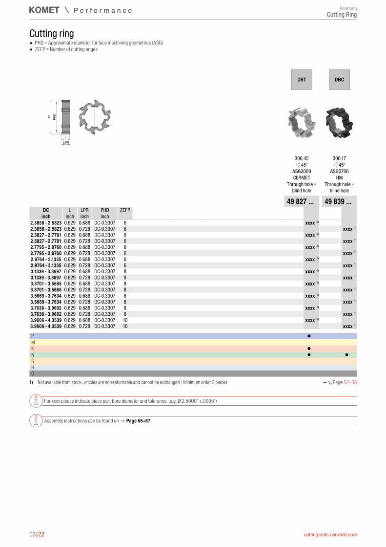
Cutting ring ▲ PHD = Approximate diameter for face machining geometries (ASG) ▲ ZEFP = Number of cutting edges
DC
LLPR
PHD
DBG-P DBG-P K10 TiN TiN
300.65 300.65 300.25 300.05 300.05 45° 45° 30/2° 45° 45°
ASG3000 ASG0106 ASG03 ASG3000 ASG0106HM HM HM HM HM
Through hole + blind hole
Through hole + blind hole
Through hole + blind hole
Through hole + blind hole
Through hole + blind hole
49 836 ... 49 835 ... 49 832 ... 49 823 ... 49 824 ...DC L LPR PHD ZEFP
inch inch inch inch 2.3858 - 2.5823 0.629 0.728 DC-0.3307 6 xxxxxxxxx 1) xxxxxxxxx 1) xxxxxxxxx 1) xxxxxxxxx 1) xxxxxxxxx 1)
2.5827 - 2.7791 0.629 0.728 DC-0.3307 6 xxxxxxxxx 1) xxxxxxxxx 1) xxxxxxxxx 1) xxxxxxxxx 1) xxxxxxxxx2.7795 - 2.9760 0.629 0.728 DC-0.3307 6 xxxxxxxxx 1) xxxxxxxxx 1) xxxxxxxxx 1) xxxxxxxxx 1) xxxxxxxxx2.9764 - 3.1335 0.629 0.728 DC-0.3307 6 xxxxxxxxx 1) xxxxxxxxx 1) xxxxxxxxx 1) xxxxxxxxx 1) xxxxxxxxx3.1339 - 3.3697 0.629 0.728 DC-0.3307 8 xxxxxxxxx 1) xxxxxxxxx 1) xxxxxxxxx 1) xxxxxxxxx 1) xxxxxxxxx3.3701 - 3.5665 0.629 0.728 DC-0.3307 8 xxxxxxxxx 1) xxxxxxxxx 1) xxxxxxxxx 1) xxxxxxxxx 1) xxxxxxxxx3.5669 - 3.7634 0.629 0.728 DC-0.3307 8 xxxxxxxxx 1) xxxxxxxxx 1) xxxxxxxxx 1) xxxxxxxxx 1) xxxxxxxxx3.7638 - 3.9602 0.629 0.728 DC-0.3307 8 xxxxxxxxx 1) xxxxxxxxx 1) xxxxxxxxx 1) xxxxxxxxx 1) xxxxxxxxx3.9606 - 4.3539 0.629 0.728 DC-0.3307 10 xxxxxxxxx 1) xxxxxxxxx 1) xxxxxxxxx 1) xxxxxxxxx 1) xxxxxxxxx
P ● ● ○ ●M ● ○K ● ○ N ○ S ● H O
1) Not available from stock, articles are non-returnable and cannot be exchanged / Minimum order 2 pieces → vc Page 52–56
For xxxx please indicate piece part bore diameter and tolerance. (e.g. Ø 2.5000" ±.0005")
Assembly instructions can be found on → Page 66+67
ReamingCutting Ring
03|22
Cutting ring ▲ PHD = Approximate diameter for face machining geometries (ASG) ▲ ZEFP = Number of cutting edges
DC
LLPR
PHD
DST DBC
300.45 300.17 45° 45°
ASG3000 ASG0706CERMET HM
Through hole + blind hole
Through hole + blind hole
49 827 ... 49 839 ...DC L LPR PHD ZEFP
inch inch inch inch 2.3858 - 2.5823 0.629 0.688 DC-0.3307 6 xxxxxxxxx 1)
2.3858 - 2.5823 0.629 0.728 DC-0.3307 6 xxxxxxxxx 1)
2.5827 - 2.7791 0.629 0.688 DC-0.3307 6 xxxxxxxxx 1)
2.5827 - 2.7791 0.629 0.728 DC-0.3307 6 xxxxxxxxx 1)
2.7795 - 2.9760 0.629 0.688 DC-0.3307 6 xxxxxxxxx 1)
2.7795 - 2.9760 0.629 0.728 DC-0.3307 6 xxxxxxxxx 1)
2.9764 - 3.1335 0.629 0.688 DC-0.3307 6 xxxxxxxxx 1)
2.9764 - 3.1335 0.629 0.728 DC-0.3307 6 xxxxxxxxx 1)
3.1339 - 3.3697 0.629 0.688 DC-0.3307 8 xxxxxxxxx 1)
3.1339 - 3.3697 0.629 0.728 DC-0.3307 8 xxxxxxxxx 1)
3.3701 - 3.5665 0.629 0.688 DC-0.3307 8 xxxxxxxxx 1)
3.3701 - 3.5665 0.629 0.728 DC-0.3307 8 xxxxxxxxx 1)
3.5669 - 3.7634 0.629 0.688 DC-0.3307 8 xxxxxxxxx 1)
3.5669 - 3.7634 0.629 0.728 DC-0.3307 8 xxxxxxxxx 1)
3.7638 - 3.9602 0.629 0.688 DC-0.3307 8 xxxxxxxxx 1)
3.7638 - 3.9602 0.629 0.728 DC-0.3307 8 xxxxxxxxx 1)
3.9606 - 4.3539 0.629 0.688 DC-0.3307 10 xxxxxxxxx 1)
3.9606 - 4.3539 0.629 0.728 DC-0.3307 10 xxxxxxxxx 1)
P ● M K ● N ● ●S H O
1) Not available from stock, articles are non-returnable and cannot be exchanged / Minimum order 2 pieces → vc Page 52–56
For xxxx please indicate piece part bore diameter and tolerance. (e.g. Ø 2.5000" ±.0005")
Assembly instructions can be found on → Page 66+67
ReamingCutting Ring

3
03|23
Cutting ring ▲ PHD = Approximate diameter for face machining geometries (ASG) ▲ ZEFP = Number of cutting edges
DC
LLPR
PHD
TiN DST
300.05 300.45 25° 25°
ASG4000 ASG4000HM CERMET
Through hole Through hole
49 831 ... 49 828 ...DC L LPR PHD ZEFP
inch inch inch inch 2.3858 - 2.5823 0.629 0.728 DC-0.3307 6 xxxxxxxxx 1)
2.3858 - 2.5823 0.629 0.688 DC-0.3307 6 xxxxxxxxx 1)
2.5827 - 2.7791 0.629 0.728 DC-0.3307 6 xxxxxxxxx 1)
2.5827 - 2.7791 0.629 0.688 DC-0.3307 6 xxxxxxxxx 1)
2.7795 - 2.9760 0.629 0.728 DC-0.3307 6 xxxxxxxxx 1)
2.7795 - 2.9760 0.629 0.688 DC-0.3307 6 xxxxxxxxx 1)
2.9764 - 3.1335 0.629 0.728 DC-0.3307 6 xxxxxxxxx 1)
2.9764 - 3.1335 0.629 0.688 DC-0.3307 6 xxxxxxxxx 1)
3.1339 - 3.3697 0.629 0.728 DC-0.3307 8 xxxxxxxxx 1)
3.1339 - 3.3697 0.629 0.688 DC-0.3307 8 xxxxxxxxx 1)
3.3701 - 3.5665 0.629 0.728 DC-0.3307 8 xxxxxxxxx 1)
3.3701 - 3.5665 0.629 0.688 DC-0.3307 8 xxxxxxxxx 1)
3.5669 - 3.7634 0.629 0.728 DC-0.3307 8 xxxxxxxxx 1)
3.5669 - 3.7634 0.629 0.688 DC-0.3307 8 xxxxxxxxx 1)
3.7638 - 3.9602 0.629 0.728 DC-0.3307 8 xxxxxxxxx 1)
3.7638 - 3.9602 0.629 0.688 DC-0.3307 8 xxxxxxxxx 1)
3.9606 - 4.3539 0.629 0.728 DC-0.3307 10 xxxxxxxxx 1)
3.9606 - 4.3539 0.629 0.688 DC-0.3307 10 xxxxxxxxx 1)
P ● ●M K N ○ S H O
1) Not available from stock, articles are non-returnable and cannot be exchanged / Minimum order 2 pieces → vc Page 52–56
For xxxx please indicate piece part bore diameter and tolerance. (e.g. Ø 2.5000" ±.0005")
Assembly instructions can be found on → Page 66+67
ReamingCutting Ring

03|24
Cutting ring holder for through hole machiningSupply details:Holder includes positioning pin, taper ring and adjusting nut. Does not include cutting ring.
DCONMS
DCd
OAL
LPR
f
A A≤ 3xD ≤ 5xD
40 892 ... 40 893 ...DC KOMET no. OAL LPR DCONMS DCONMS d f
inch inch inch inch mm mm inch2.3858 - 2.7795 503.76.008 7.460 4.133 1.259 32 40.000 0.964 40892071992.3858 - 2.7795 504.76.009 12.657 9.330 1.259 32 40.000 0.964 40893071992.7795 - 3.1338 503.76.009 7.460 4.133 1.259 32 40.000 0.964 40892080992.7795 - 3.1338 504.76.010 12.657 9.330 1.259 32 40.000 0.964 40893080993.1339 - 3.5669 503.76.010 8.011 4.133 1.574 40 56.200 1.122 40892091993.1339 - 3.5669 504.76.011 13.326 9.448 1.574 40 56.200 1.122 40893091993.5669 - 3.9606 503.76.011 8.011 4.133 1.574 40 56.200 1.122 40892101993.5669 - 3.9606 504.76.012 13.326 9.448 1.574 40 56.200 1.122 4089310199
Position Pin Taper Ring Adjustic Nut
40 950 ... 40 950 ... 40 950 ...Spare partsDC 2.3858 - 2.7795 4095050700 4095050500 40950501002.7795 - 3.1338 4095050700 4095050500 40950501003.1339 - 3.5669 4095050800 4095050600 40950502003.5669 - 3.9606 4095050800 4095050600 4095050200
Assembly instructions can be found on → Page 66+67
ReamingCutting Ring

3
03|25
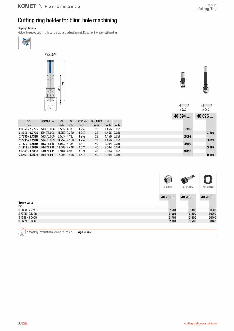
Cutting ring holder for blind hole machiningSupply details:Holder includes bushing, taper screw and adjusting nut. Does not include cutting ring.
DCONMS
OAL
LPR
DCd f
A A≤ 3xD ≤ 5xD
40 895 ... 40 897 ...DC KOMET no. OAL LPR DCONMS DCONMS d f
inch inch inch inch mm inch inch2.3858 - 2.7795 513.81.008 6.555 4.133 1.259 32 1.456 0.059 40895071992.3858 - 2.7795 514.81.008 11.752 9.330 1.259 32 1.456 0.059 40897071992.7795 - 3.1338 513.81.009 6.555 4.133 1.259 32 1.456 0.059 40895080992.7795 - 3.1338 514.81.009 11.752 9.330 1.259 32 1.456 0.059 40897080993.1339 - 3.5669 513.81.010 6.948 4.133 1.574 40 2.094 0.059 40895091993.1339 - 3.5669 514.81.010 12.263 9.448 1.574 40 2.094 0.059 40897091993.5669 - 3.9606 513.81.011 6.948 4.133 1.574 40 2.094 0.059 40895101993.5669 - 3.9606 514.81.011 12.263 9.448 1.574 40 2.094 0.059 4089710199
Bushing Taper Screw Adjustic Nut
40 950 ... 40 950 ... 40 950 ...Spare partsDC 2.3858 - 2.7795 4095051500 4095051300 40950503002.7795 - 3.1338 4095051600 4095051300 40950503003.1339 - 3.5669 4095051700 4095051400 40950504003.5669 - 3.9606 4095051800 4095051400 4095050400
Assembly instructions can be found on → Page 66+67
ReamingCutting Ring
03|26
Cutting ring holder for blind hole machiningSupply details:Holder includes bushing, taper screw and adjusting nut. Does not include cutting ring.
DCONMS
OAL
LPR
DCd f
A A≤ 3xD ≤ 5xD
40 894 ... 40 896 ...DC KOMET no. OAL LPR DCONMS DCONMS d f
inch inch inch inch mm inch inch2.3858 - 2.7795 513.76.008 6.555 4.133 1.259 32 1.456 0.059 40894071992.3858 - 2.7795 514.76.008 11.752 9.330 1.259 32 1.456 0.059 40896071992.7795 - 3.1338 513.76.009 6.555 4.133 1.259 32 1.456 0.059 40894080992.7795 - 3.1338 514.76.009 11.752 9.330 1.259 32 1.456 0.059 40896080993.1339 - 3.5669 513.76.010 6.948 4.133 1.574 40 2.094 0.059 40894091993.1339 - 3.5669 514.76.010 12.263 9.448 1.574 40 2.094 0.059 40896091993.5669 - 3.9606 513.76.011 6.948 4.133 1.574 40 2.094 0.059 40894101993.5669 - 3.9606 514.76.011 12.263 9.448 1.574 40 2.094 0.059 4089610199
Bushing Taper Screw Adjustic Nut
40 950 ... 40 950 ... 40 950 ...Spare partsDC 2.3858 - 2.7795 4095051500 4095051100 40950503002.7795 - 3.1338 4095051600 4095051100 40950503003.1339 - 3.5669 4095051700 4095051200 40950504003.5669 - 3.9606 4095051800 4095051200 4095050400
Assembly instructions can be found on → Page 66+67
ReamingCutting Ring
3
03|27
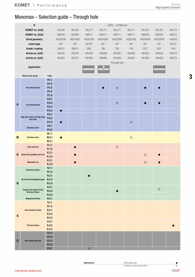
Ø .2205 – 1.0196 inchKOMET no. (3xD) 56J.65 56.J65 56J.17 56J.71 56J.71 56J.71 56J.93 56J.93 56J.21KOMET no. (5xD) 56R.65 56.R65 56R.17 56R.71 56R.71 56R.71 56R.93 56R.93 56R.21Grind geometry ASG0106 ASG3000 ASG0706 ASG4000 ASG3000 ASG0106 ASG4000 ASG3000 ASG03
Lead angle 45° 45° 45°/8° 45° 45° 45° 25° 45° 30°/2°Grade / coating DBG-P DBG-P DBC TiN TIN TiN DST DST K10Article no. (3xD) 49 652 49 676 49 648 49 688 49 605 49 656 49 635 49 625 49 672Article no. (5xD) 49 653 49 677 49 649 49 689 49 606 49 661 49 636 49 626 49 673
ApplicationThrough hole
Monomax – Selection guide – Through hole
Applications: Main application ●Additional range of application ○
Material sub-group Index
P
Non alloyed steel
P.1.1P.1.2P.1.3P.1.4P.1.5
Low alloyed steel
P.2.1P.2.2P.2.3P.2.4
High-alloy steel and high-alloy tool steel
P.3.1P.3.2P.3.3
Stainless steelP.4.1P.4.2
M Stainless steelM.1.1M.2.1M.3.1
K
Grey cast ironK.1.1K.1.2
Spherulitic graphite cast ironK.2.1K.2.2
Malleable ironK.3.1K.3.2
N
Aluminum alloys,N.1.1N.1.2
Aluminium-GusslegierungenN.2.1N.2.2N.2.3
Copper and copper alloys (Bronze, Brass)
N.3.1N.3.2N.3.3
Magnesium alloys N.4.1
S
Heat resistant alloys
S.1.1S.1.2S.2.1S.2.2S.2.3
Titanium alloysS.3.1S.3.2S.3.3
O Non-metal materials
O.1.1O.1.2O.2.1O.2.2O.3.1
● ○ ● ●
○ ● ●
●
● ○
● ○
● ○
● ○ ●
● ○ ●
●
● ○
●
○
ReamingHigh-speed reamers
3
03|28
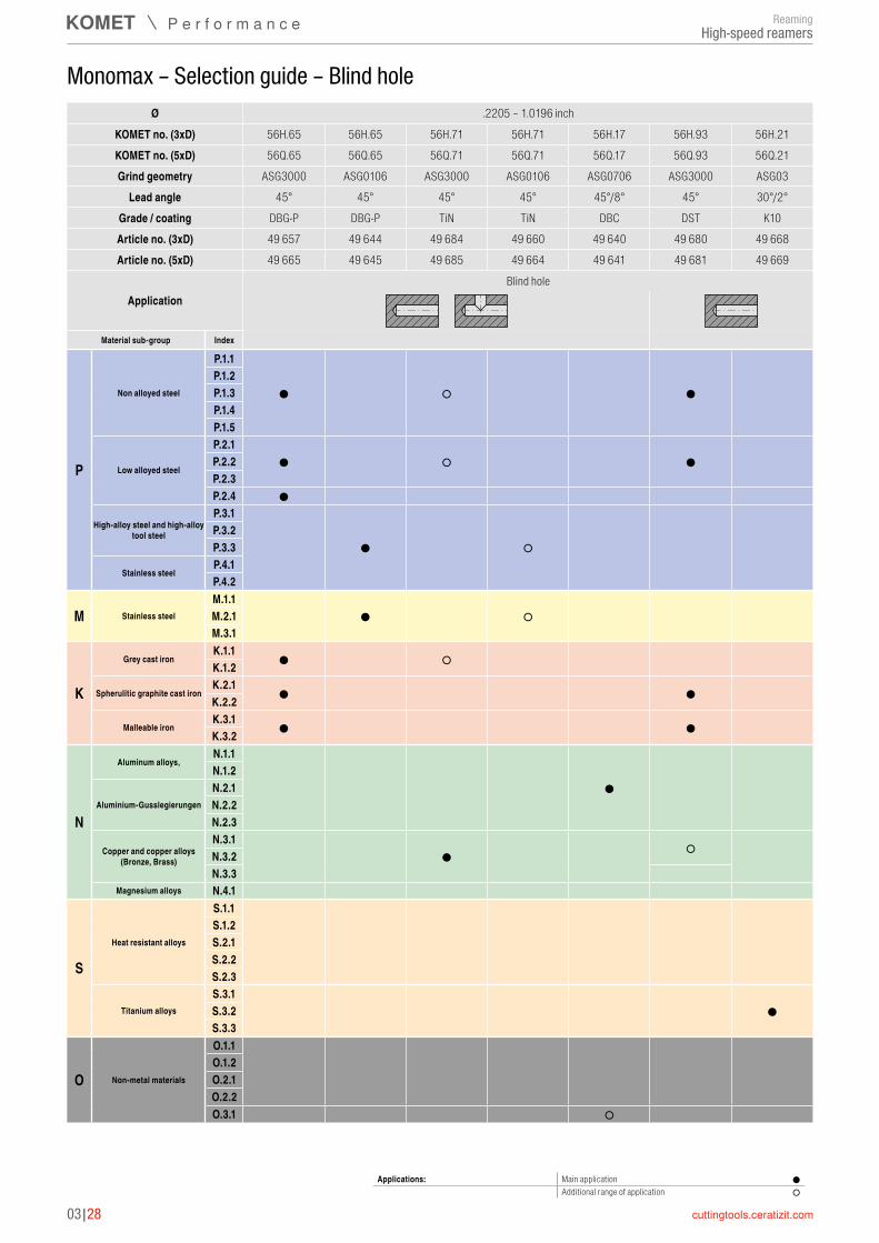
Monomax – Selection guide – Blind hole
Applications: Main application ●Additional range of application ○
Ø .2205 – 1.0196 inchKOMET no. (3xD) 56H.65 56H.65 56H.71 56H.71 56H.17 56H.93 56H.21KOMET no. (5xD) 56Q.65 56Q.65 56Q.71 56Q.71 56Q.17 56Q.93 56Q.21Grind geometry ASG3000 ASG0106 ASG3000 ASG0106 ASG0706 ASG3000 ASG03
Lead angle 45° 45° 45° 45° 45°/8° 45° 30°/2°Grade / coating DBG-P DBG-P TiN TiN DBC DST K10Article no. (3xD) 49 657 49 644 49 684 49 660 49 640 49 680 49 668Article no. (5xD) 49 665 49 645 49 685 49 664 49 641 49 681 49 669
ApplicationBlind hole
Material sub-group Index
P
Non alloyed steel
P.1.1P.1.2P.1.3P.1.4P.1.5
Low alloyed steel
P.2.1P.2.2P.2.3P.2.4
High-alloy steel and high-alloy tool steel
P.3.1P.3.2P.3.3
Stainless steelP.4.1P.4.2
M Stainless steelM.1.1M.2.1M.3.1
K
Grey cast ironK.1.1K.1.2
Spherulitic graphite cast ironK.2.1K.2.2
Malleable ironK.3.1K.3.2
N
Aluminum alloys,N.1.1N.1.2
Aluminium-GusslegierungenN.2.1N.2.2N.2.3
Copper and copper alloys (Bronze, Brass)
N.3.1N.3.2N.3.3
Magnesium alloys N.4.1
S
Heat resistant alloys
S.1.1S.1.2S.2.1S.2.2S.2.3
Titanium alloysS.3.1S.3.2S.3.3
O Non-metal materials
O.1.1O.1.2O.2.1O.2.2O.3.1
● ○ ●
● ○ ●
●
● ○
● ○
● ○
● ●
● ●
●
● ○
●
○
ReamingHigh-speed reamers
3
03|29
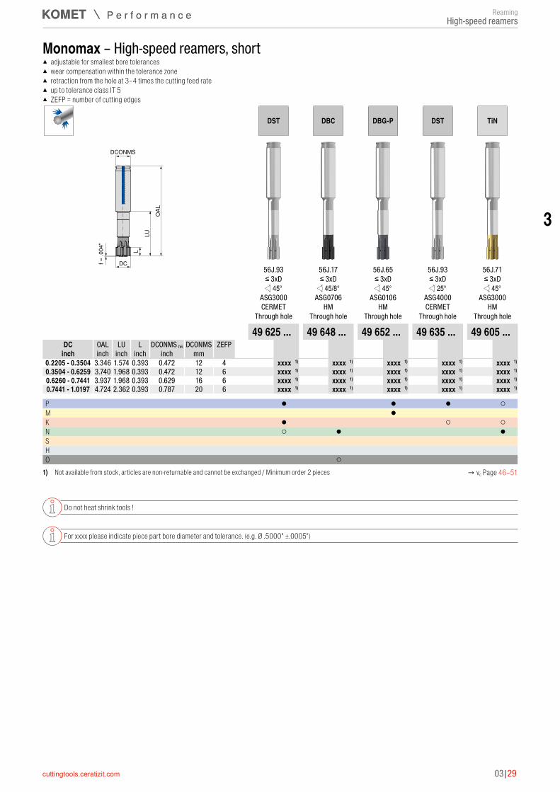
Monomax – High-speed reamers, short ▲ adjustable for smallest bore tolerances ▲ wear compensation within the tolerance zone ▲ retraction from the hole at 3–4 times the cutting feed rate ▲ up to tolerance class IT 5 ▲ ZEFP = number of cutting edges
OAL
L
DC
DCONMSLU
f ≈ .0
04"
DST DBC DBG-P DST TiN
56J.93 56J.17 56J.65 56J.93 56J.71≤ 3xD ≤ 3xD ≤ 3xD ≤ 3xD ≤ 3xD 45° 45/8° 45° 25° 45°
ASG3000 ASG0706 ASG0106 ASG4000 ASG3000CERMET HM HM CERMET HM
Through hole Through hole Through hole Through hole Through hole
49 625 ... 49 648 ... 49 652 ... 49 635 ... 49 605 ...DC OAL LU L DCONMS h6 DCONMS ZEFP
inch inch inch inch inch mm 0.2205 - 0.3504 3.346 1.574 0.393 0.472 12 4 xxxxxxxxx 1) xxxxxxxxx 1) xxxxxxxxx 1) xxxxxxxxx 1) xxxxxxxxx 1)
0.3504 - 0.6259 3.740 1.968 0.393 0.472 12 6 xxxxxxxxx 1) xxxxxxxxx 1) xxxxxxxxx 1) xxxxxxxxx 1) xxxxxxxxx 1)
0.6260 - 0.7441 3.937 1.968 0.393 0.629 16 6 xxxxxxxxx 1) xxxxxxxxx 1) xxxxxxxxx 1) xxxxxxxxx 1) xxxxxxxxx 1)
0.7441 - 1.0197 4.724 2.362 0.393 0.787 20 6 xxxxxxxxx 1) xxxxxxxxx 1) xxxxxxxxx 1) xxxxxxxxx 1) xxxxxxxxx 1)
P ● ● ● ○M ● K ● ○ ○N ○ ● ●S H O ○
1) Not available from stock, articles are non-returnable and cannot be exchanged / Minimum order 2 pieces → vc Page 46–51
Do not heat shrink tools !
For xxxx please indicate piece part bore diameter and tolerance. (e.g. Ø .5000" ±.0005")
ReamingHigh-speed reamers

03|30
Monomax – High-speed reamers, short ▲ adjustable for smallest bore tolerances ▲ wear compensation within the tolerance zone ▲ retraction from the hole at 3–4 times the cutting feed rate ▲ up to tolerance class IT 5 ▲ ZEFP = number of cutting edges
OAL
L
DC
DCONMSLU
f ≈ .0
04"
K10 DBG-P TiN TiN
56J.21 56J.65 56J.17 56J.71≤ 3xD ≤ 3xD ≤ 3xD ≤ 3xD
30/2° 45° 25° 45°ASG03 ASG3000 ASG4000 ASG0106
HM HM HM HMThrough hole Through hole Through hole Through hole
49 672 ... 49 676 ... 49 688 ... 49 656 ...DC OAL LU L DCONMS h6 DCONMS ZEFP
inch inch inch inch inch mm 0.2205 - 0.3504 3.346 1.574 0.393 0.472 12 4 xxxxxxxxx 1) xxxxxxxxx 1) xxxxxxxxx 1) xxxxxxxxx 1)
0.3504 - 0.6259 3.740 1.968 0.393 0.472 12 6 xxxxxxxxx 1) xxxxxxxxx 1) xxxxxxxxx 1) xxxxxxxxx 1)
0.6260 - 0.7441 3.937 1.968 0.393 0.629 16 6 xxxxxxxxx 1) xxxxxxxxx 1) xxxxxxxxx 1) xxxxxxxxx 1)
0.7441 - 1.0197 4.724 2.362 0.393 0.787 20 6 xxxxxxxxx 1) xxxxxxxxx 1) xxxxxxxxx 1) xxxxxxxxx 1)
P ● ○M ○K ● N S ● H O
1) Not available from stock, articles are non-returnable and cannot be exchanged / Minimum order 2 pieces → vc Page 46–51
Do not heat shrink tools !
For xxxx please indicate piece part bore diameter and tolerance. (e.g. Ø .5000" ±.0005")
ReamingHigh-speed reamers

3
03|31
Monomax – High-speed reamers, short ▲ adjustable for smallest bore tolerances ▲ wear compensation within the tolerance zone ▲ retraction from the hole at 3–4 times the cutting feed rate ▲ up to tolerance class IT 5 ▲ ZEFP = number of cutting edges
OAL
L
DC
DCONMSLU
f ≈ .0
04"
DBG-P DBC DBG-P
56H.65 56H.17 56H.65≤ 3xD ≤ 3xD ≤ 3xD 45° 45/8° 45°
ASG0106 ASG0706 ASG3000HM HM HM
Blind hole Blind hole Blind hole
49 644 ... 49 640 ... 49 657 ...DC OAL LU L DCONMS h6 DCONMS ZEFP
inch inch inch inch inch mm 0.2205 - 0.3504 3.346 1.574 0.393 0.472 12 4 xxxxxxxxx 1) xxxxxxxxx 1) xxxxxxxxx 1)
0.3504 - 0.6259 3.740 1.968 0.393 0.472 12 6 xxxxxxxxx 1) xxxxxxxxx 1) xxxxxxxxx 1)
0.6260 - 0.7441 3.937 1.968 0.393 0.629 16 6 xxxxxxxxx 1) xxxxxxxxx 1) xxxxxxxxx 1)
0.7441 - 1.0197 4.724 2.362 0.393 0.787 20 6 xxxxxxxxx 1) xxxxxxxxx 1) xxxxxxxxx 1)
P ● ●M ● K ●N ● S H O ○
1) Not available from stock, articles are non-returnable and cannot be exchanged / Minimum order 2 pieces → vc Page 46–51
Do not heat shrink tools !
For xxxx please indicate piece part bore diameter and tolerance. (e.g. Ø .5000" ±.0005")
ReamingHigh-speed reamers

03|32
Monomax – High-speed reamers, short ▲ adjustable for smallest bore tolerances ▲ wear compensation within the tolerance zone ▲ retraction from the hole at 3–4 times the cutting feed rate ▲ up to tolerance class IT 5 ▲ ZEFP = number of cutting edges
OAL
L
DC
DCONMSLU
f ≈ .0
04"
TiN K10 DST TiN
56H.71 56H.21 56H.93 56H.71≤ 3xD ≤ 3xD ≤ 3xD ≤ 3xD 45° 30/2° 45° 45°
ASG0106 ASG03 ASG3000 ASG3000HM HM CERMET HM
Blind hole Blind hole Blind hole Blind hole
49 660 ... 49 668 ... 49 680 ... 49 684 ...DC OAL LU L DCONMS h6 DCONMS ZEFP
inch inch inch inch inch mm 0.2205 - 0.3504 3.346 1.574 0.393 0.472 12 4 xxxxxxxxx 1) xxxxxxxxx 1) xxxxxxxxx 1) xxxxxxxxx 1)
0.3504 - 0.6259 3.740 1.968 0.393 0.472 12 6 xxxxxxxxx 1) xxxxxxxxx 1) xxxxxxxxx 1) xxxxxxxxx 1)
0.6260 - 0.7441 3.937 1.968 0.393 0.629 16 6 xxxxxxxxx 1) xxxxxxxxx 1) xxxxxxxxx 1) xxxxxxxxx 1)
0.7441 - 1.0197 4.724 2.362 0.393 0.787 20 6 xxxxxxxxx 1) xxxxxxxxx 1) xxxxxxxxx 1) xxxxxxxxx 1)
P ○ ● ○M ○ K ● ○N ○ ●S ● H O
1) Not available from stock, articles are non-returnable and cannot be exchanged / Minimum order 2 pieces → vc Page 46–51
Do not heat shrink tools !
For xxxx please indicate piece part bore diameter and tolerance. (e.g. Ø .5000" ±.0005")
ReamingHigh-speed reamers
3
03|33
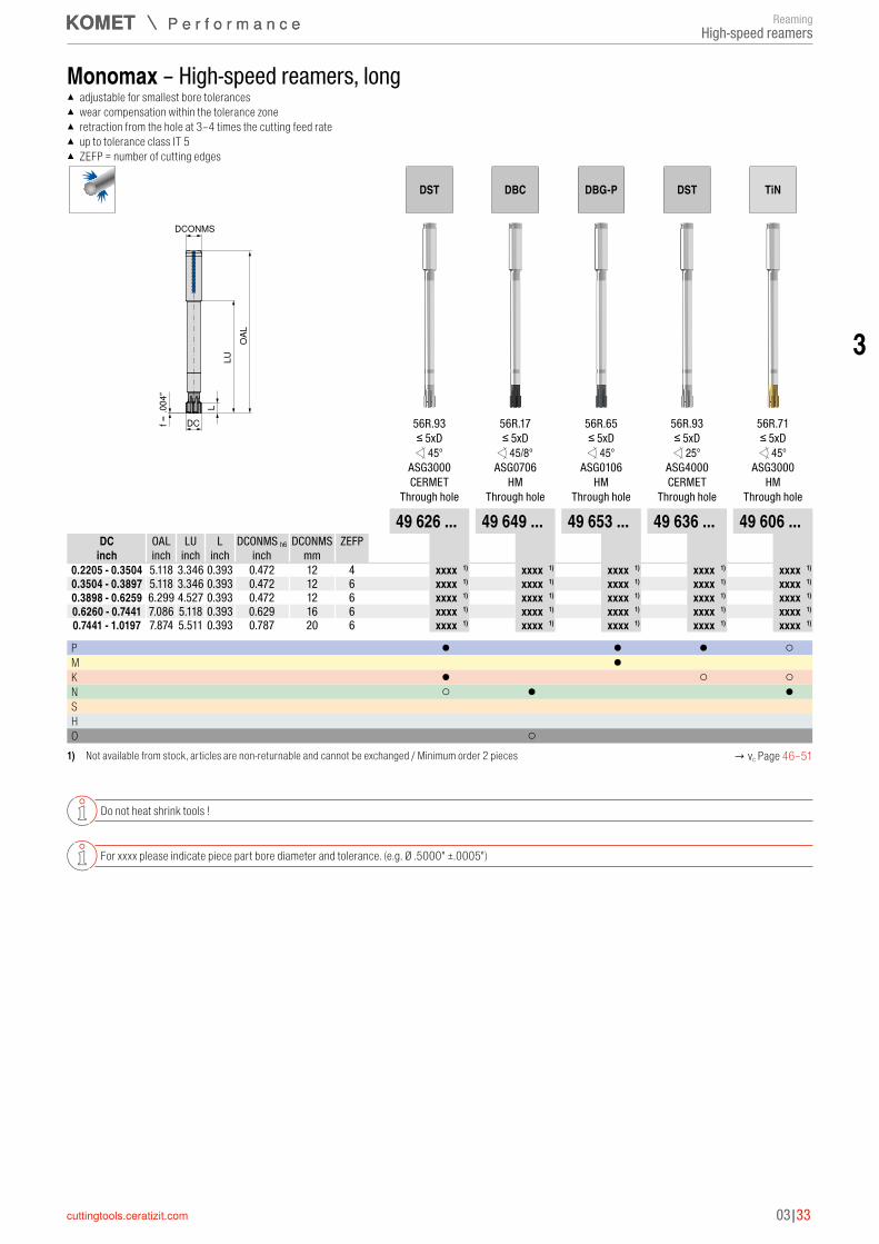
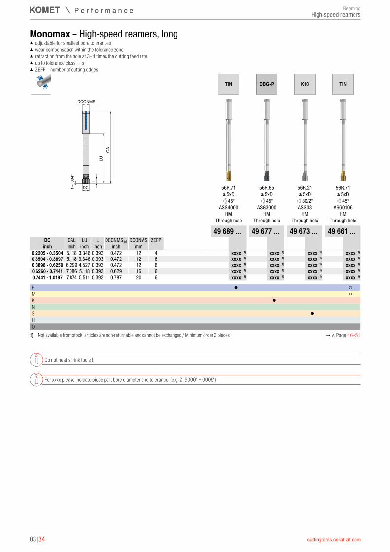
Monomax – High-speed reamers, long ▲ adjustable for smallest bore tolerances ▲ wear compensation within the tolerance zone ▲ retraction from the hole at 3–4 times the cutting feed rate ▲ up to tolerance class IT 5 ▲ ZEFP = number of cutting edges
OAL
L
DC
DCONMSLU
f ≈ .0
04"
DST DBC DBG-P DST TiN
56R.93 56R.17 56R.65 56R.93 56R.71≤ 5xD ≤ 5xD ≤ 5xD ≤ 5xD ≤ 5xD 45° 45/8° 45° 25° 45°
ASG3000 ASG0706 ASG0106 ASG4000 ASG3000CERMET HM HM CERMET HM
Through hole Through hole Through hole Through hole Through hole
49 626 ... 49 649 ... 49 653 ... 49 636 ... 49 606 ...DC OAL LU L DCONMS h6 DCONMS ZEFP
inch inch inch inch inch mm 0.2205 - 0.3504 5.118 3.346 0.393 0.472 12 4 xxxxxxxxx 1) xxxxxxxxx 1) xxxxxxxxx 1) xxxxxxxxx 1) xxxxxxxxx 1)
0.3504 - 0.3897 5.118 3.346 0.393 0.472 12 6 xxxxxxxxx 1) xxxxxxxxx 1) xxxxxxxxx 1) xxxxxxxxx 1) xxxxxxxxx 1)
0.3898 - 0.6259 6.299 4.527 0.393 0.472 12 6 xxxxxxxxx 1) xxxxxxxxx 1) xxxxxxxxx 1) xxxxxxxxx 1) xxxxxxxxx 1)
0.6260 - 0.7441 7.086 5.118 0.393 0.629 16 6 xxxxxxxxx 1) xxxxxxxxx 1) xxxxxxxxx 1) xxxxxxxxx 1) xxxxxxxxx 1)
0.7441 - 1.0197 7.874 5.511 0.393 0.787 20 6 xxxxxxxxx 1) xxxxxxxxx 1) xxxxxxxxx 1) xxxxxxxxx 1) xxxxxxxxx 1)
P ● ● ● ○M ● K ● ○ ○N ○ ● ●S H O ○
1) Not available from stock, articles are non-returnable and cannot be exchanged / Minimum order 2 pieces → vc Page 46–51
Do not heat shrink tools !
For xxxx please indicate piece part bore diameter and tolerance. (e.g. Ø .5000" ±.0005")
ReamingHigh-speed reamers
03|34
Monomax – High-speed reamers, long ▲ adjustable for smallest bore tolerances ▲ wear compensation within the tolerance zone ▲ retraction from the hole at 3–4 times the cutting feed rate ▲ up to tolerance class IT 5 ▲ ZEFP = number of cutting edges
OAL
L
DC
DCONMSLU
f ≈ .0
04"
TiN DBG-P K10 TiN
56R.71 56R.65 56R.21 56R.71≤ 5xD ≤ 5xD ≤ 5xD ≤ 5xD 45° 45° 30/2° 45°
ASG4000 ASG3000 ASG03 ASG0106HM HM HM HM
Through hole Through hole Through hole Through hole
49 689 ... 49 677 ... 49 673 ... 49 661 ...DC OAL LU L DCONMS h6 DCONMS ZEFP
inch inch inch inch inch mm 0.2205 - 0.3504 5.118 3.346 0.393 0.472 12 4 xxxxxxxxx 1) xxxxxxxxx 1) xxxxxxxxx 1) xxxxxxxxx 1)
0.3504 - 0.3897 5.118 3.346 0.393 0.472 12 6 xxxxxxxxx 1) xxxxxxxxx 1) xxxxxxxxx 1) xxxxxxxxx 1)
0.3898 - 0.6259 6.299 4.527 0.393 0.472 12 6 xxxxxxxxx 1) xxxxxxxxx 1) xxxxxxxxx 1) xxxxxxxxx 1)
0.6260 - 0.7441 7.086 5.118 0.393 0.629 16 6 xxxxxxxxx 1) xxxxxxxxx 1) xxxxxxxxx 1) xxxxxxxxx 1)
0.7441 - 1.0197 7.874 5.511 0.393 0.787 20 6 xxxxxxxxx 1) xxxxxxxxx 1) xxxxxxxxx 1) xxxxxxxxx 1)
P ● ○M ○K ● N S ● H O
1) Not available from stock, articles are non-returnable and cannot be exchanged / Minimum order 2 pieces → vc Page 46–51
Do not heat shrink tools !
For xxxx please indicate piece part bore diameter and tolerance. (e.g. Ø .5000" ±.0005")
ReamingHigh-speed reamers

3
03|35
Monomax – High-speed reamers, long ▲ adjustable for smallest bore tolerances ▲ wear compensation within the tolerance zone ▲ retraction from the hole at 3–4 times the cutting feed rate ▲ up to tolerance class IT 5 ▲ ZEFP = number of cutting edges
OAL
L
DC
DCONMSLU
f ≈ .0
04"
DBG-P DBC DBG-P
56Q.65 56Q.17 56Q.65≤ 5xD ≤ 5xD ≤ 5xD 45° 45/8° 45°
ASG0106 ASG0706 ASG3000HM HM HM
Blind hole Blind hole Blind hole
49 645 ... 49 641 ... 49 665 ...DC OAL LU L DCONMS h6 DCONMS ZEFP
inch inch inch inch inch mm 0.2205 - 0.3504 5.118 3.346 0.393 0.472 12 4 xxxxxxxxx 1) xxxxxxxxx 1) xxxxxxxxx 1)
0.3504 - 0.3897 5.118 3.346 0.393 0.472 12 6 xxxxxxxxx 1) xxxxxxxxx 1) xxxxxxxxx 1)
0.3898 - 0.6259 6.299 4.527 0.393 0.472 12 6 xxxxxxxxx 1) xxxxxxxxx 1) xxxxxxxxx 1)
0.6260 - 0.7441 7.086 5.118 0.393 0.629 16 6 xxxxxxxxx 1) xxxxxxxxx 1) xxxxxxxxx 1)
0.7441 - 1.0197 7.874 5.511 0.393 0.787 20 6 xxxxxxxxx 1) xxxxxxxxx 1) xxxxxxxxx 1)
P ● ●M ● K ●N ● S H O ○
1) Not available from stock, articles are non-returnable and cannot be exchanged / Minimum order 2 pieces → vc Page 46–51
Do not heat shrink tools !
For xxxx please indicate piece part bore diameter and tolerance. (e.g. Ø .5000" ±.0005")
ReamingHigh-speed reamers

03|36
Monomax – High-speed reamers, long ▲ adjustable for smallest bore tolerances ▲ wear compensation within the tolerance zone ▲ retraction from the hole at 3–4 times the cutting feed rate ▲ up to tolerance class IT 5 ▲ ZEFP = number of cutting edges
OAL
L
DC
DCONMSLU
f ≈ .0
04"
DST TiN K10 TiN
56Q.93 56Q.71 56Q.21 56Q.71≤ 5xD ≤ 5xD ≤ 5xD ≤ 5xD 45° 45° 30/2° 45°
ASG3000 ASG3000 ASG03 ASG0106CERMET HM HM HM
Blind hole Blind hole Blind hole Blind hole
49 681 ... 49 685 ... 49 669 ... 49 664 ...DC OAL LU L DCONMS h6 DCONMS ZEFP
inch inch inch inch inch mm 0.2205 - 0.3504 5.118 3.346 0.393 0.472 12 4 xxxxxxxxx 1) xxxxxxxxx 1) xxxxxxxxx 1) xxxxxxxxx 1)
0.3504 - 0.3897 5.118 3.346 0.393 0.472 12 6 xxxxxxxxx 1) xxxxxxxxx 1) xxxxxxxxx 1) xxxxxxxxx 1)
0.3898 - 0.6259 6.299 4.527 0.393 0.472 12 6 xxxxxxxxx 1) xxxxxxxxx 1) xxxxxxxxx 1) xxxxxxxxx 1)
0.6260 - 0.7441 7.086 5.118 0.393 0.629 16 6 xxxxxxxxx 1) xxxxxxxxx 1) xxxxxxxxx 1) xxxxxxxxx 1)
0.7441 - 1.0197 7.874 5.511 0.393 0.787 20 6 xxxxxxxxx 1) xxxxxxxxx 1) xxxxxxxxx 1) xxxxxxxxx 1)
P ● ○ ○M ○K ● ○ N ○ ● S ● H O
1) Not available from stock, articles are non-returnable and cannot be exchanged / Minimum order 2 pieces → vc Page 46–51
Do not heat shrink tools !
For xxxx please indicate piece part bore diameter and tolerance. (e.g. Ø .5000" ±.0005")
ReamingHigh-speed reamers

3
03|37
Ø .1575 – .7913 inchKOMET no. 690.10 690.11 690.13 690.14
Number of flutes 2 4 2 4Grind geometry ASG1101 ASG1101
Lead angle 45° 45°Grade / coating PCD-U PCD-U
Article no. 49 200 49 201 49 204 49 205
ApplicationThrough hole Blind hole
PCD Reamers – Selection guide
Applications: Main application ●Additional range of application ○
Material sub-group Index
P
Non alloyed steel
P.1.1P.1.2P.1.3P.1.4P.1.5
Low alloyed steel
P.2.1P.2.2P.2.3P.2.4
High-alloy steel and high-alloy tool steel
P.3.1P.3.2P.3.3
Stainless steelP.4.1P.4.2
M Stainless steelM.1.1M.2.1M.3.1
K
Grey cast ironK.1.1K.1.2
Spherulitic graphite cast ironK.2.1K.2.2
Malleable ironK.3.1K.3.2
N
Aluminum alloys,N.1.1N.1.2
Aluminium-GusslegierungenN.2.1N.2.2N.2.3
Copper and copper alloys (Bronze, Brass)
N.3.1N.3.2N.3.3
Magnesium alloys N.4.1
S
Heat resistant alloys
S.1.1S.1.2S.2.1S.2.2S.2.3
Titanium alloysS.3.1S.3.2S.3.3
O Non-metal materials
O.1.1O.1.2O.2.1O.2.2O.3.1
● ●
● ●
ReamingPCD Reamers
03|38
PCD – Reamers ▲ Solid Carbide body ▲ PHD = Diameter for face machining ▲ ZEFP = Number of cutting edges
DCONMS
LUO
AL
DC
L
PHD
PCD-U PCD-U
690.13 690.14~A ~A
90° 90°ASG1101 ASG1101
HM HMBlind hole Blind hole
49 204 ... 49 205 ...DC OAL L LU PHD DCONMS h6 DCONMS ZEFP
inch inch inch inch inch inch mm 0.1575 - 0.1811 2.519 0.275 1.102 DC-0.0945 0.236 6 2 xxxxxxxxx 1)
0.1811 - 0.2008 2.519 0.275 1.102 DC-0.1024 0.236 6 2 xxxxxxxxx 1)
0.2008 - 0.2205 2.519 0.275 1.102 DC-0.1063 0.236 6 2 xxxxxxxxx 1)
0.2205 - 0.2402 2.795 0.275 1.377 DC-0.1102 0.236 6 2 xxxxxxxxx 1)
0.2402 - 0.2598 2.992 0.275 1.574 DC-0.1339 0.314 8 2 xxxxxxxxx 1)
0.2599 - 0.2795 2.992 0.275 1.574 DC-0.1339 0.314 8 2 xxxxxxxxx 1)
0.2796 - 0.2992 2.992 0.275 1.574 DC-0.1339 0.314 8 2 xxxxxxxxx 1)
0.2993 - 0.3189 2.992 0.275 1.574 DC-0.1417 0.314 8 2 xxxxxxxxx 1)
0.3189 - 0.3386 3.346 0.275 1.574 DC-0.1417 0.472 12 2 xxxxxxxxx 1)
0.3386 - 0.3583 3.346 0.275 1.574 DC-0.1614 0.472 12 2 xxxxxxxxx 1)
0.3583 - 0.3976 3.346 0.275 1.574 DC-0.1811 0.472 12 2 xxxxxxxxx 1)
0.3780 - 0.3976 3.346 0.275 1.574 DC-0.1496 0.472 12 4 xxxxxxxxx 1)
0.3977 - 0.4567 3.740 0.275 1.968 DC-0.1969 0.472 12 2 xxxxxxxxx 1)
0.3977 - 0.4567 3.740 0.275 1.968 DC-0.1496 0.472 12 4 xxxxxxxxx 1)
0.4567 - 0.5551 3.740 0.275 1.968 DC-0.2362 0.472 12 2 xxxxxxxxx 1)
0.4567 - 0.5551 3.740 0.275 1.968 DC-0.1496 0.472 12 4 xxxxxxxxx 1)
0.5552 - 0.5945 3.858 0.275 1.968 DC-0.2598 0.629 16 2 xxxxxxxxx 1)
0.5552 - 0.5945 3.858 0.275 1.968 DC-0.1535 0.629 16 4 xxxxxxxxx 1)
0.5945 - 0.6339 3.858 0.275 1.968 DC-0.2795 0.629 16 2 xxxxxxxxx 1)
0.5945 - 0.6339 3.858 0.275 1.968 DC-0.1535 0.629 16 4 xxxxxxxxx 1)
0.6339 - 0.7126 4.251 0.275 2.362 DC-0.3150 0.629 16 2 xxxxxxxxx 1)
0.6339 - 0.7126 4.251 0.275 2.362 DC-0.1811 0.629 16 4 xxxxxxxxx 1)
0.7126 - 0.7913 4.330 0.275 2.362 DC-0.3386 0.787 20 2 xxxxxxxxx 1)
0.7126 - 0.7913 4.330 0.275 2.362 DC-0.1811 0.787 20 4 xxxxxxxxx 1)
P M K N ● ●S H O
1) Not available from stock, articles are non-returnable and cannot be exchanged / Minimum order 2 pieces → vc Page 62
For xxxx please indicate piece part bore diameter and tolerance. (e.g. Ø .5000" ±.0005")
ReamingPCD Reamers
3
03|39
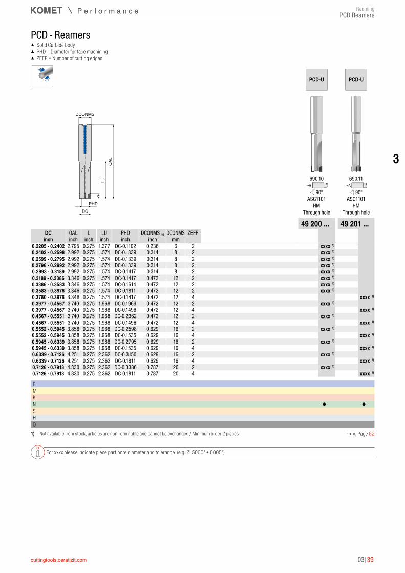
PCD - Reamers ▲ Solid Carbide body ▲ PHD = Diameter for face machining ▲ ZEFP = Number of cutting edges
DCONMS
LUO
AL
DC
L
PHD
PCD-U PCD-U
690.10 690.11~A ~A
90° 90°ASG1101 ASG1101
HM HMThrough hole Through hole
49 200 ... 49 201 ...DC OAL L LU PHD DCONMS h6 DCONMS ZEFP
inch inch inch inch inch inch mm 0.2205 - 0.2402 2.795 0.275 1.377 DC-0.1102 0.236 6 2 xxxxxxxxx 1)
0.2402 - 0.2598 2.992 0.275 1.574 DC-0.1339 0.314 8 2 xxxxxxxxx 1)
0.2599 - 0.2795 2.992 0.275 1.574 DC-0.1339 0.314 8 2 xxxxxxxxx 1)
0.2796 - 0.2992 2.992 0.275 1.574 DC-0.1339 0.314 8 2 xxxxxxxxx 1)
0.2993 - 0.3189 2.992 0.275 1.574 DC-0.1417 0.314 8 2 xxxxxxxxx 1)
0.3189 - 0.3386 3.346 0.275 1.574 DC-0.1417 0.472 12 2 xxxxxxxxx 1)
0.3386 - 0.3583 3.346 0.275 1.574 DC-0.1614 0.472 12 2 xxxxxxxxx 1)
0.3583 - 0.3976 3.346 0.275 1.574 DC-0.1811 0.472 12 2 xxxxxxxxx 1)
0.3780 - 0.3976 3.346 0.275 1.574 DC-0.1417 0.472 12 4 xxxxxxxxx 1)
0.3977 - 0.4567 3.740 0.275 1.968 DC-0.1969 0.472 12 2 xxxxxxxxx 1)
0.3977 - 0.4567 3.740 0.275 1.968 DC-0.1496 0.472 12 4 xxxxxxxxx 1)
0.4567 - 0.5551 3.740 0.275 1.968 DC-0.2362 0.472 12 2 xxxxxxxxx 1)
0.4567 - 0.5551 3.740 0.275 1.968 DC-0.1496 0.472 12 4 xxxxxxxxx 1)
0.5552 - 0.5945 3.858 0.275 1.968 DC-0.2598 0.629 16 2 xxxxxxxxx 1)
0.5552 - 0.5945 3.858 0.275 1.968 DC-0.1535 0.629 16 4 xxxxxxxxx 1)
0.5945 - 0.6339 3.858 0.275 1.968 DC-0.2795 0.629 16 2 xxxxxxxxx 1)
0.5945 - 0.6339 3.858 0.275 1.968 DC-0.1535 0.629 16 4 xxxxxxxxx 1)
0.6339 - 0.7126 4.251 0.275 2.362 DC-0.3150 0.629 16 2 xxxxxxxxx 1)
0.6339 - 0.7126 4.251 0.275 2.362 DC-0.1811 0.629 16 4 xxxxxxxxx 1)
0.7126 - 0.7913 4.330 0.275 2.362 DC-0.3386 0.787 20 2 xxxxxxxxx 1)
0.7126 - 0.7913 4.330 0.275 2.362 DC-0.1811 0.787 20 4 xxxxxxxxx 1)
P M K N ● ●S H O
1) Not available from stock, articles are non-returnable and cannot be exchanged / Minimum order 2 pieces → vc Page 62
For xxxx please indicate piece part bore diameter and tolerance. (e.g. Ø .5000" ±.0005")
ReamingPCD Reamers

03|40
Material sub-group Index Composition / Structure / Heat treatment Tensile strength Material number
Material designation
Material number
Material designationlbf/in²* / HB / HRC
P
Unalloyed steel
P.1.1 < 0.15 % C Annealed 60900 lbf/in² / 125 HB 1.0401 1015 1.0301 1010
P.1.2< 0.45 % C
Annealed 92800 lbf/in² / 190 HB 1.1191 1045 1.0737 12L14
P.1.3 Tempered 121800 lbf/in² / 250 HB 1.1191 1045 1.0503 1043
P.1.4< 0.75 % C
Annealed 132000 lbf/in² / 270 HB 1.1223 1060 1.0535 1055
P.1.5 Tempered 146500 lbf/in² / 300 HB 1.1223 1060 1.1274 1095
Low-alloy steel
P.2.1 Annealed 88500 lbf/in² / 180 HB 1.7131 5115 1.6523 8620
P.2.2 Tempered 134900 lbf/in² / 275 HB 1.7131 5115 1.6582 4340
P.2.3 Tempered 146500 lbf/in² / 300 HB 1.7225 4142 1.7131 5115
P.2.4 Tempered 174000 lbf/in² / 375 HB 1.7225 4142 17223 4140
High-alloy steel and high-alloy tool steel
P.3.1 Annealed 98600 lbf/in² / 200 HB 1.4021 420 1.2379 D2
P.3.2 Hardened and tempered 159500 lbf/in² / 300 HB 1.2343 H11 1.3343 M2
P.3.3 Hardened and tempered 188500 lbf/in² / 400 HB 1.2343 H11 1.2363 A2
Stainless steelP.4.1 Ferritic / martensitic Annealed 98600 lbf/in² / 200 HB 1.4016 430 1.4125 440C
P.4.2 Martensitic Tempered 117500 lbf/in² / 250 HB 1.4112 S44003 1.4021 420
M Stainless steel
M.1.1 Austenitic / austenitic-ferritic Quenched 88500 lbf/in² / 200 HB 1.4301 304 1.4401 316
M.2.1 Austenitic Tempered 300 HB 1.4841 314 1.4568 17-7 PH
M.3.1 Austenitic / ferritic (Duplex) 113100 lbf/in² / 230 HB 1.4462 S32205 1.4410 S32750
K
Grey cast ironK.1.1 Pearlitic / ferritic 88500 lbf/in² / 180 HB 0.6010 A48-20B 0.6025 A48-40 B
K.1.2 Pearlitic (martensitic) 127600 lbf/in² / 260 HB 0.6030 A48-45B 0.6040 A48-60 B
Spherulitic graphite cast iron
K.2.1 Ferritic 78300 lbf/in² / 160 HB 0.7040 60-40-18 0.7050 65-45-12
K.2.2 Pearlitic 122600 lbf/in² / 250 HB 0.7070 100-70-03 0.7660 A439 Type D2
Malleable ironK.3.1 Ferritic 63800 lbf/in² / 130 HB 0.8035 GTW-35-04
K.3.2 Pearlitic 113100 lbf/in² / 230 HB 0.8170 70003
N
Aluminium wrought alloyN.1.1 Non-hardenable 60 HB 3.0255 A91060 3.0255 A91060
N.1.2 Hardenable 49300 lbf/in² / 100 HB 3.1355 2024 3.1355 2024
Cast aluminium alloy
N.2.1 ≤ 12 % Si, non-hardenable 36300 lbf/in² / 75 HB 3.2581 A04130 / A413-0 3.2581 A04130 / A413-0
N.2.2 ≤ 12 % Si, hardenable 43500 lbf/in² / 90 HB 3.2134 G-AlSi5Cu1Mg
N.2.3 > 12 % Si, non-hardenable 63800 lbf/in² / 130 HB G-AlSi17Cu4Mg
Copper and copper alloys (bronze/brass)
N.3.1 Free-machining alloys, PB > 1 % 54400 lbf/in² / 110 HB 2.0380 CuZn39Pb2 (Ms58) 2.0380 C37700
N.3.2 CuZn, CuSnZn 43500 lbf/in² / 90 HB 2.0331 CuZn15 2.0331 C34000
N.3.3 CuSn, lead-free copper and electrolytic copper 49300 lbf/in² / 100 HB 2.0060 E-Cu57
Magnesium alloys N.4.1 Magnesium and magnesium alloys 70 HB 3.5612 MgAl6Zn
S
Heat-resistant alloys
S.1.1Fe - basis
Annealed 98600 lbf/in² / 200 HB 1.4864 X12NiCrSi 36-16 1.4864 330
S.1.2 137800 lbf/in² / 280 HB 1.4980 X6NiCrTiMoVB25-15-2 1.4980 S66286
S.2.1Ni or Co basis
Annealed 121800 lbf/in² / 250 HB 2.4856 Inconel 625 2.4812 Hastelloy C
S.2.2 171100 lbf/in² / 350 HB 2.4952 Nimonic 80A 2.4668 Inconel 718
S.2.3 Cast 156600 lbf/in² / 320 HB 2.4674 Nimocast PK24 2.4670 Nimocast 713
Titanium alloys
S.3.1 Pure titanium 5800 lbf/in² 3.7025 Ti99,8
S.3.2 Alpha + beta alloys 152300 lbf/in² 3.7165 TiAl6V4
S.3.3 Beta alloys 203100 lbf/in² / 410 HB Ti555.3 Ti-5Al-5V-5Mo-3Cr
HHardened steel
H.1.1 Hardened and tempered 46-55 HRC
H.1.2 Hardened and tempered 56-60 HRC
H.1.3 Hardened and tempered 61-65 HRC
H.1.4 Hardened and tempered 66-70 HRC
Chilled iron H.2.1 Cast 400 HB
Hardened cast iron H.3.1 Hardened and tempered 55 HRC
O Non-metal materials
O.1.1 Plastics, duroplastic ≤ 21800 lbf/in²
O.1.2 Plastics, thermoplastic ≤ 14500 lbf/in²
O.2.1 Aramid fibre-reinforced ≤ 145000 lbf/in²
O.2.2 Glass/carbon-fibre reinforced ≤ 145000 lbf/in²
O.3.1 Graphite
* Tensile Strength at Rupture (Rm)
Material examples for cutting data tables
ReamingCutting data

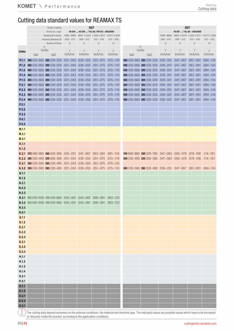
P.1.1 490 (430–660) 390 (330–520) .031–.043 .039–.055 .051–.075 .075–.110P.1.2 490 (430–660) 390 (330–520) .031–.043 .039–.055 .051–.075 .075–.110P.1.3 490 (430–660) 390 (330–520) .031–.043 .039–.055 .051–.075 .075–.110P.1.4 490 (430–660) 390 (330–520) .031–.043 .039–.055 .051–.075 .075–.110P.1.5 490 (430–660) 390 (330–520) .031–.043 .039–.055 .051–.075 .075–.110P.2.1 490 (430–660) 390 (330–520) .031–.043 .039–.055 .051–.075 .075–.110P.2.2 490 (430–660) 390 (330–520) .031–.043 .039–.055 .051–.075 .075–.110P.2.3 490 (430–660) 390 (330–520) .031–.043 .039–.055 .051–.075 .075–.110P.2.4 490 (430–660) 390 (330–520) .031–.043 .039–.055 .051–.075 .075–.110P.3.1 100 (80–160) 100 (80–130) .024–.035 .031–.043 .043–.059 .059–.091P.3.2 100 (80–160) 100 (80–130) .024–.035 .031–.043 .043–.059 .059–.091P.3.3 100 (80–160) 100 (80–130) .024–.035 .031–.043 .043–.059 .059–.091P.4.1 150 (110–200) 130 (110–160) .024–.035 .031–.043 .043–.059 .059–.091P.4.2 150 (110–200) 130 (110–160) .024–.035 .031–.043 .043–.059 .059–.091M.1.1 150 (110–200) 130 (110–160) .024–.035 .031–.043 .043–.059 .059–.091M.2.1 150 (110–200) 130 (110–160) .024–.035 .031–.043 .043–.059 .059–.091M.3.1 100 (80–160) 100 (80–130) .024–.035 .031–.043 .043–.059 .059–.091K.1.1 490 (430–720) 390 (330–490) .035–.051 .047–.067 .063–.091 .091–.134K.1.2 490 (430–720) 390 (330–490) .035–.051 .047–.067 .063–.091 .091–.134K.2.1 570 (490–980) 490 (430–590) .035–.051 .047–.067 .063–.091 .091–.134K.2.2 390 (330–590) 390 (330–490) .031–.043 .039–.055 .051–.075 .075–.110K.3.1 390 (330–590) 390 (330–490) .031–.043 .039–.055 .051–.075 .075–.110K.3.2 390 (330–590) 390 (330–490) .031–.043 .039–.055 .051–.075 .075–.110N.1.1N.1.2N.2.1N.2.2N.2.3N.3.1N.3.2N.3.3N.4.1S.1.1S.1.2S.2.1S.2.2S.2.3S.3.1S.3.2S.3.3H.1.1H.1.2H.1.3H.1.4H.2.1H.3.1O.1.1O.1.2O.2.1O.2.2O.3.1
03|41
3
Grade / coating DBG-P DBG-PArticle no. / type 49 586 ..., 49 585 … / 75J.65, 75H.65 – ASG3000 49 521 …, 49 571 … / 75J.65, 75H.65 – ASG0106
Nominal Ø in inches .7086–.8660 .8661–1.2519 1.2520–2.0471 2.0472–2.5590 .7086–.8660 .8661–1.2519 1.2520–2.0471 2.0472–2.5590Reaming allowance Ø .008 – .012 .008 – .012 .012 – .016 .012 – .016 .008 – .012 .008 – .012 .012 – .016 .012 – .016
Number of flutes 6 6 8 10 6 6 8 10
Indexvc vc
ft/min f f f f ft/min f f f f3xD 5xD inch/rev. inch/rev. inch/rev. inch/rev. 3xD 5xD inch/rev. inch/rev. inch/rev. inch/rev.
Cutting data standard values for REAMAX TS
The cutting data depend extremely on the external conditions, the material and machine type. The indicated values are possible values which have to be increased or reduced, inside the bracket, according to the application conditions.
ReamingCutting data

P.1.1 330 (260–460) 260 (200–390) .031–.004 .039–.055 .051–.075 .075–.110 330 (260–460) 260 (200–390) .039–.051 .047–.067 .067–.091 .094–.134P.1.2 330 (260–460) 260 (200–390) .031–.004 .039–.055 .051–.075 .075–.110 330 (260–460) 260 (200–390) .039–.051 .047–.067 .067–.091 .094–.134P.1.3 330 (260–460) 260 (200–390) .031–.004 .039–.055 .051–.075 .075–.110 330 (260–460) 260 (200–390) .039–.051 .047–.067 .067–.091 .094–.134P.1.4 330 (260–460) 260 (200–390) .031–.004 .039–.055 .051–.075 .075–.110 330 (260–460) 260 (200–390) .039–.051 .047–.067 .067–.091 .094–.134P.1.5 330 (260–460) 260 (200–390) .031–.004 .039–.055 .051–.075 .075–.110 330 (260–460) 260 (200–390) .039–.051 .047–.067 .067–.091 .094–.134P.2.1 330 (260–460) 260 (200–390) .031–.004 .039–.055 .051–.075 .075–.110P.2.2 330 (260–460) 260 (200–390) .031–.004 .039–.055 .051–.075 .075–.110P.2.3 330 (260–460) 260 (200–390) .031–.004 .039–.055 .051–.075 .075–.110P.2.4 330 (260–460) 260 (200–390) .031–.004 .039–.055 .051–.075 .075–.110P.3.1P.3.2P.3.3P.4.1P.4.2M.1.1M.2.1M.3.1K.1.1 260 (200–430) 260 (200–390) .035–.051 .047–.067 .063–.091 .091–.134K.1.2 260 (200–430) 260 (200–390) .035–.051 .047–.067 .063–.091 .091–.134K.2.1K.2.2K.3.1K.3.2N.1.1N.1.2N.2.1N.2.2N.2.3N.3.1 390 (330–660) 390 (330–660) .035–.051 .043–.067 .059–.091 .091–.134N.3.2 260 (200–490) 260 (200–390) .028–.043 .035–.055 .047–.075 .067–.102N.3.3 390 (330–660) 390 (330–490) .028–.043 .035–.055 .047–.075 .067–.102N.4.1S.1.1S.1.2S.2.1S.2.2S.2.3S.3.1S.3.2S.3.3H.1.1H.1.2H.1.3H.1.4H.2.1H.3.1O.1.1O.1.2O.2.1O.2.2O.3.1
03|42
Grade / coating TiN TiNArticle no. / type 49 534 …, 49 535 ... / 75J.71, 75H.71 – ASG3000 49 596 … / 75J.71 – ASG4000
Nominal Ø in inches .7086–.8660 .8661–1.2519 1.2520–2.0471 2.0472–2.5590 .7086–.8660 .8661–1.2519 1.2520–2.0471 2.0472–2.5590Reaming allowance Ø .008 – .012 .008 – .012 .012 – .016 .012 – .016 .008 – .012 .008 – .012 .012 – .016 .012 – .016
Number of flutes 6 6 8 10 6 6 8 10
Indexvc vc
ft/min f f f f ft/min f f f f3xD 5xD inch/rev. inch/rev. inch/rev. inch/rev. 3xD 5xD inch/rev. inch/rev. inch/rev. inch/rev.
Cutting data standard values for REAMAX TS
The cutting data depend extremely on the external conditions, the material and machine type. The indicated values are possible values which have to be increased or reduced, inside the bracket, according to the application conditions.
Cutting dataReaming

P.1.1P.1.2P.1.3P.1.4P.1.5P.2.1P.2.2P.2.3P.2.4P.3.1 70 (50–110) 70 (50–90) .024–.035 .031–.043 .043–.059 .059–.091P.3.2 70 (50–110) 70 (50–90) .024–.035 .031–.043 .043–.059 .059–.091P.3.3 70 (50–110) 70 (50–90) .024–.035 .031–.043 .043–.059 .059–.091P.4.1 100 (70–130) 90 (70–110) .024–.035 .031–.043 .043–.059 .059–.091P.4.2 100 (70–130) 90 (70–110) .024–.035 .031–.043 .043–.059 .059–.091M.1.1 100 (70–130) 90 (70–110) .024–.035 .031–.043 .043–.059 .059–.091M.2.1 100 (70–130) 90 (70–110) .024–.035 .031–.043 .043–.059 .059–.091M.3.1 70 (50–110) 70 (50–90) .024–.035 .031–.043 .043–.059 .059–.091K.1.1K.1.2K.2.1K.2.2K.3.1K.3.2N.1.1 490 (430–980) 490 (430–660) .035–.051 .043–.067 .059–.091 .087–.134N.1.2 490 (430–980) 490 (430–660) .035–.051 .043–.067 .059–.091 .087–.134N.2.1 660 (590–980) 490 (430–660) .035–.051 .043–.067 .059–.091 .087–.134N.2.2 660 (590–980) 490 (430–660) .035–.051 .043–.067 .059–.091 .087–.134N.2.3 660 (590–980) 490 (430–660) .035–.051 .043–.067 .059–.091 .087–.134N.3.1N.3.2N.3.3N.4.1 490 (430–980) 490 (430–660) .035–.051 .043–.067 .059–.091 .087–.134S.1.1S.1.2S.2.1S.2.2S.2.3S.3.1S.3.2S.3.3H.1.1H.1.2H.1.3H.1.4H.2.1H.3.1O.1.1O.1.2O.2.1O.2.2O.3.1 820 (720–890) 820 (720–890) .035–.051 .043–.067 .059–.091 .087–.134
03|43
3
Grade / coating TiN DBCArticle no. / type 49 520 …, 49 527 ... / 75J.71, 75H.71 – ASG0106 49 526 …, 49 580 ... / 75J.17, 75H.17 – ASG0706
Nominal Ø in inches .7086–.8660 .8661–1.2519 1.2520–2.0471 2.0472–2.5590 .7086–.8660 .8661–1.2519 1.2520–2.0471 2.0472–2.5590Reaming allowance Ø .008 – .012 .008 – .012 .012 – .016 .012 – .016 .008 – .012 .008 – .012 .012 – .016 .012 – .016
Number of flutes 6 6 8 10 6 6 8 10
Indexvc vc
ft/min f f f f ft/min f f f f3xD 5xD inch/rev. inch/rev. inch/rev. inch/rev. 3xD 5xD inch/rev. inch/rev. inch/rev. inch/rev.
Cutting data standard values for REAMAX TS
The cutting data depend extremely on the external conditions, the material and machine type. The indicated values are possible values which have to be increased or reduced, inside the bracket, according to the application conditions.
ReamingCutting data
P.1.1 490 (430–660) 390 (330–520) .031–.043 .039–.055 .051–.075 .075–.110 490 (430–660) 390 (330–520) .039–.051 .047–.067 .067–.091 .094–.134P.1.2 490 (430–660) 390 (330–520) .031–.043 .039–.055 .051–.075 .075–.110 490 (430–660) 390 (330–520) .039–.051 .047–.067 .067–.091 .094–.134P.1.3 490 (430–660) 390 (330–520) .031–.043 .039–.055 .051–.075 .075–.110 490 (430–660) 390 (330–520) .039–.051 .047–.067 .067–.091 .094–.134P.1.4 490 (430–660) 390 (330–520) .031–.043 .039–.055 .051–.075 .075–.110 490 (430–660) 390 (330–520) .039–.051 .047–.067 .067–.091 .094–.134P.1.5 490 (430–660) 390 (330–520) .031–.043 .039–.055 .051–.075 .075–.110 490 (430–660) 390 (330–520) .039–.051 .047–.067 .067–.091 .094–.134P.2.1 490 (430–660) 390 (330–520) .031–.043 .039–.055 .051–.075 .075–.110 490 (430–660) 390 (330–520) .039–.051 .047–.067 .067–.091 .094–.134P.2.2 490 (430–660) 390 (330–520) .031–.043 .039–.055 .051–.075 .075–.110 490 (430–660) 390 (330–520) .039–.051 .047–.067 .067–.091 .094–.134P.2.3 490 (430–660) 390 (330–520) .031–.043 .039–.055 .051–.075 .075–.110 490 (430–660) 390 (330–520) .039–.051 .047–.067 .067–.091 .094–.134P.2.4 490 (430–660) 390 (330–520) .031–.043 .039–.055 .051–.075 .075–.110 490 (430–660) 390 (330–520) .039–.051 .047–.067 .067–.091 .094–.134P.3.1P.3.2P.3.3P.4.1P.4.2M.1.1M.2.1M.3.1K.1.1K.1.2K.2.1 570 (490–980) 490 (430–590) .035–.051 .047–.067 .063–.091 .091–.134 740 (660–980) 590 (520–790) .047–.063 .059–.079 .079–.106 .114–.161K.2.2 380 (330–490) 330 (260–390) .031–.043 .039–.055 .051–.075 .075–.110 390 (330–490) 330 (260–390) .047–.063 .059–.079 .079–.106 .114–.161K.3.1 390 (330–590) 390 (330–490) .031–.043 .039–.055 .051–.075 .075–.110K.3.2 390 (330–590) 390 (330–490) .031–.043 .039–.055 .051–.075 .075–.110 390 (330–590) 390 (330–490) .039–.051 .047–.067 .067–.091 .094–.134N.1.1N.1.2N.2.1N.2.2N.2.3N.3.1 490 (430–1050) 490 (430–660) .035–.051 .043–.067 .059–.091 .083–.122N.3.2 490 (430–1050) 490 (430–660) .035–.051 .043–.067 .059–.091 .083–.122N.3.3N.4.1S.1.1S.1.2S.2.1S.2.2S.2.3S.3.1S.3.2S.3.3H.1.1H.1.2H.1.3H.1.4H.2.1H.3.1O.1.1O.1.2O.2.1O.2.2O.3.1
03|44
Grade / coating DST DSTArticle no. / type 49 544 …, 40 539 ... / 75J.93, 75H.93 – ASG3000 49 597 … / 75J.93 – ASG4000
Nominal Ø in inches .7086–.8660 .8661–1.2519 1.2520–2.0471 2.0472–2.5590 .7086–.8660 .8661–1.2519 1.2520–2.0471 2.0472–2.5590Reaming allowance Ø .008 – .012 .008 – .012 .012 – .016 .012 – .016 .008 – .012 .008 – .012 .012 – .016 .012 – .016
Number of flutes 6 6 8 10 6 6 8 10
Indexvc vc
ft/min f f f f ft/min f f f f3xD 5xD inch/rev. inch/rev. inch/rev. inch/rev. 3xD 5xD inch/rev. inch/rev. inch/rev. inch/rev.
Cutting data standard values for REAMAX TS
The cutting data depend extremely on the external conditions, the material and machine type. The indicated values are possible values which have to be increased or reduced, inside the bracket, according to the application conditions.
ReamingCutting data

P.1.1 490 (430–660) 390 (330–520) .031–.043 .043–.055 .051–.075 .075–.110P.1.2 490 (430–660) 390 (330–520) .031–.043 .043–.055 .051–.075 .075–.110P.1.3 490 (430–660) 390 (330–520) .031–.043 .043–.055 .051–.075 .075–.110P.1.4 490 (430–660) 390 (330–520) .031–.043 .043–.055 .051–.075 .075–.110P.1.5 490 (430–660) 390 (330–520) .031–.043 .043–.055 .051–.075 .075–.110P.2.1 490 (430–660) 390 (330–520) .031–.043 .043–.055 .051–.075 .075–.110P.2.2 490 (430–660) 390 (330–520) .031–.043 .043–.055 .051–.075 .075–.110P.2.3 490 (430–660) 390 (330–520) .031–.043 .043–.055 .051–.075 .075–.110P.2.4 490 (430–660) 390 (330–520) .031–.043 .043–.055 .051–.075 .075–.110P.3.1P.3.2P.3.3P.4.1P.4.2M.1.1M.2.1M.3.1K.1.1K.1.2K.2.1 570 (490–980) 490 (430–590) .035–.051 .047–.067 .063–.091 .091–.134K.2.2 390 (330–490) 330 (260–390) .031–.043 .043–.055 .051–.075 .075–.110K.3.1 390 (330–590) 390 (330–490) .031–.043 .043–.055 .051–.075 .075–.110K.3.2 390 (330–590) 390 (330–490) .031–.043 .043–.055 .051–.075 .075–.110N.1.1N.1.2N.2.1N.2.2N.2.3N.3.1 490 (430–1050) 490 (330–660) .035–.051 .043–.067 .059–.091 .083–.122N.3.2 490 (430–1050) 490 (330–660) .035–.051 .043–.067 .059–.091 .083–.122N.3.3N.4.1S.1.1S.1.2S.2.1S.2.2S.2.3S.3.1 30 (20–40) 30 (20–40) .024–.035 .031–.047 .043–.063 .063–.094S.3.2 30 (20–40) 30 (20–40) .024–.035 .031–.047 .043–.063 .063–.094S.3.3 30 (20–40) 30 (20–40) .024–.035 .031–.047 .043–.063 .063–.094H.1.1H.1.2H.1.3H.1.4H.2.1H.3.1O.1.1O.1.2O.2.1O.2.2O.3.1
03|45
3
Grade / coating DST K10Article no. / type 49 539 … / 75H.93 – ASG3000 49 531 …, 49 530 ... / 75J.21, 75H.21 – ASG03
Nominal Ø in inches .7086–.8660 .8661–1.2519 1.2520–2.0471 2.0472–2.5590 .7086–.8660 .8661–1.2519 1.2520–2.0471 2.0472–2.5590Reaming allowance Ø .008 – .012 .008 – .012 .012 – .016 .012 – .016 .008 – .012 .008 – .012 .012 – .016 .012 – .016
Number of flutes 6 6 8 10 6 6 8 10
Indexvc vc
ft/min f f f f ft/min f f f f3xD 5xD inch/rev. inch/rev. inch/rev. inch/rev. 3xD 5xD inch/rev. inch/rev. inch/rev. inch/rev.
Cutting data standard values for REAMAX TS
The cutting data depend extremely on the external conditions, the material and machine type. The indicated values are possible values which have to be increased or reduced, inside the bracket, according to the application conditions.
ReamingCutting data
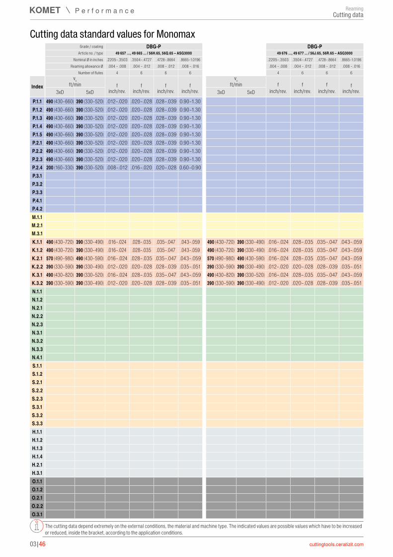
P.1.1 490 (430–660) 390 (330–520) .012–.020 .020–.028 .028–.039 0.90–1.30P.1.2 490 (430–660) 390 (330–520) .012–.020 .020–.028 .028–.039 0.90–1.30P.1.3 490 (430–660) 390 (330–520) .012–.020 .020–.028 .028–.039 0.90–1.30P.1.4 490 (430–660) 390 (330–520) .012–.020 .020–.028 .028–.039 0.90–1.30P.1.5 490 (430–660) 390 (330–520) .012–.020 .020–.028 .028–.039 0.90–1.30P.2.1 490 (430–660) 390 (330–520) .012–.020 .020–.028 .028–.039 0.90–1.30P.2.2 490 (430–660) 390 (330–520) .012–.020 .020–.028 .028–.039 0.90–1.30P.2.3 490 (430–660) 390 (330–520) .012–.020 .020–.028 .028–.039 0.90–1.30P.2.4 200 (160–330) 390 (330–520) .008–.012 .016–.020 .020–.028 0.60–0.90P.3.1P.3.2P.3.3P.4.1P.4.2M.1.1M.2.1M.3.1K.1.1 490 (430–720) 390 (330–490) .016–.024 .028–.035 .035–.047 .043–.059 490 (430–720) 390 (330–490) .016–.024 .028–.035 .035–.047 .043–.059K.1.2 490 (430–720) 390 (330–490) .016–.024 .028–.035 .035–.047 .043–.059 490 (430–720) 390 (330–490) .016–.024 .028–.035 .035–.047 .043–.059K.2.1 570 (490–980) 490 (430–590) .016–.024 .028–.035 .035–.047 .043–.059 570 (490–980) 490 (430–590) .016–.024 .028–.035 .035–.047 .043–.059K.2.2 390 (330–590) 390 (330–490) .012–.020 .020–.028 .028–.039 .035–.051 390 (330–590) 390 (330–490) .012–.020 .020–.028 .028–.039 .035–.051K.3.1 490 (430–820) 390 (330–520) .016–.024 .028–.035 .035–.047 .043–.059 490 (430–820) 390 (330–520) .016–.024 .028–.035 .035–.047 .043–.059K.3.2 390 (330–590) 390 (330–490) .012–.020 .020–.028 .028–.039 .035–.051 390 (330–590) 390 (330–490) .012–.020 .020–.028 .028–.039 .035–.051N.1.1N.1.2N.2.1N.2.2N.2.3N.3.1N.3.2N.3.3N.4.1S.1.1S.1.2S.2.1S.2.2S.2.3S.3.1S.3.2S.3.3H.1.1H.1.2H.1.3H.1.4H.2.1H.3.1O.1.1O.1.2O.2.1O.2.2O.3.1
03|46
Grade / coating DBG-P DBG-PArticle no. / type 49 657 …, 49 665 ... / 56H.65, 56Q.65 – ASG3000 49 676 …, 49 677 ... / 56J.65, 56R.65 – ASG3000
Nominal Ø in inches .2205–.3503 .3504–.4727 .4728–.8664 .8665–1.0196 .2205–.3503 .3504–.4727 .4728–.8664 .8665–1.0196Reaming allowance Ø .004 – .008 .004 – .012 .008 – .012 .008 –. 016 .004 – .008 .004 – .012 .008 – .012 .008 –. 016
Number of flutes 4 6 6 6 4 6 6 6
Indexvc vc
ft/min f f f f ft/min f f f f3xD 5xD inch/rev. inch/rev. inch/rev. inch/rev. 3xD 5xD inch/rev. inch/rev. inch/rev. inch/rev.
Cutting data standard values for Monomax
The cutting data depend extremely on the external conditions, the material and machine type. The indicated values are possible values which have to be increased or reduced, inside the bracket, according to the application conditions.
ReamingCutting data

P.1.1P.1.2P.1.3P.1.4P.1.5P.2.1P.2.2P.2.3P.2.4 200 (160–330) 200 (160–330) .008–.012 .016–.020 .020–.028 .024–.035P.3.1 130 (110–200) 130 (110–200) .008–.012 .016–.020 .020–.028 .024–.035 100 (80–160) 100 (80–130) .012–.016 .016–.024 .024–.031 .028–.039P.3.2 130 (110–200) 130 (110–200) .008–.012 .016–.020 .020–.028 .024–.035 100 (80–160) 100 (80–130) .012–.016 .016–.024 .024–.031 .028–.039P.3.3 100 (80–160) 100 (80–130) .012–.016 .016–.024 .024–.031 .028–.039 100 (80–160) 100 (80–130) .012–.016 .016–.024 .024–.031 .028–.039P.4.1 150 (110–200) 130 (110–160) .012–.016 .016–.024 .024–.031 .028–.039 150 (110–200) 130 (110–160) .012–.016 .016–.024 .024–.031 .028–.039P.4.2 150 (110–200) 130 (110–160) .012–.016 .016–.024 .024–.031 .028–.039 150 (110–200) 130 (110–160) .012–.016 .016–.024 .024–.031 .028–.039M.1.1 330 (260–520) 100 (80–130) .012–.016 .016–.024 .024–.031 .028–.039 150 (110–200) 130 (110–160) .012–.016 .016–.024 .024–.031 .028–.039M.2.1 330 (260–520) 100 (80–130) .012–.016 .016–.024 .024–.031 .028–.039 150 (110–200) 130 (110–160) .012–.016 .016–.024 .024–.031 .028–.039M.3.1 330 (260–520) 100 (80–130) .012–.016 .016–.024 .024–.031 .028–.039 100 (80–160) 100 (80–130) .012–.016 .016–.024 .024–.031 .028–.039K.1.1K.1.2K.2.1K.2.2K.3.1K.3.2N.1.1N.1.2N.2.1N.2.2N.2.3N.3.1N.3.2N.3.3N.4.1S.1.1S.1.2S.2.1S.2.2S.2.3S.3.1S.3.2S.3.3H.1.1H.1.2H.1.3H.1.4H.2.1H.3.1O.1.1O.1.2O.2.1O.2.2O.3.1
03|47
3
Grade / coating DBG-P TiNArticle no. / type 49 652 …, 49 653... / 56J.65, 56R.65 – ASG0106 49 656, 49 661, 49 660, 49 664 / 56J.71, 56R.71, 56H.71, 56Q.71 – ASG0106
Nominal Ø in inches .2205–.3503 .3504–.4727 .4728–.8664 .8665–1.0196 .2205–.3503 .3504–.4727 .4728–.8664 .8665–1.0196Reaming allowance Ø .004 – .008 .004 – .012 .008 – .012 .008 –. 016 .004 – .008 .004 – .012 .008 – .012 .008 –. 016
Number of flutes 4 6 6 6 4 6 6 6
Indexvc vc
ft/min f f f f ft/min f f f f3xD 5xD inch/rev. inch/rev. inch/rev. inch/rev. 3xD 5xD inch/rev. inch/rev. inch/rev. inch/rev.
Cutting data standard values for Monomax
The cutting data depend extremely on the external conditions, the material and machine type. The indicated values are possible values which have to be increased or reduced, inside the bracket, according to the application conditions.
ReamingCutting data

P.1.1 330 (260–460) 260 (200–390) .012–.020 .020–.028 .028–.039 .035–.051 330 (260–460) 260 (200–390) .016–.024 .028–.035 .035–.047 .047–.059P.1.2 330 (260–460) 260 (200–390) .012–.020 .020–.028 .028–.039 .035–.051 330 (260–460) 260 (200–390) .016–.024 .028–.035 .035–.047 .047–.059P.1.3 330 (260–460) 260 (200–390) .012–.020 .020–.028 .028–.039 .035–.051 330 (260–460) 260 (200–390) .016–.024 .028–.035 .035–.047 .047–.059P.1.4 330 (260–460) 260 (200–390) .012–.020 .020–.028 .028–.039 .035–.051 330 (260–460) 260 (200–390) .016–.024 .028–.035 .035–.047 .047–.059P.1.5 330 (260–460) 260 (200–390) .012–.020 .020–.028 .028–.039 .035–.051 330 (260–460) 260 (200–390) .016–.024 .028–.035 .035–.047 .047–.059P.2.1 330 (260–460) 260 (200–390) .012–.020 .020–.028 .028–.039 .035–.051P.2.2 330 (260–460) 260 (200–390) .012–.020 .020–.028 .028–.039 .035–.051P.2.3 330 (260–460) 260 (200–390) .012–.020 .020–.028 .028–.039 .035–.051P.2.4P.3.1P.3.2P.3.3P.4.1P.4.2M.1.1M.2.1M.3.1K.1.1 260 (200–430) 260 (200–390) .016–.024 .028–.035 .035–.047 .043–.059K.1.2 260 (200–430) 260 (200–390) .016–.024 .028–.035 .035–.047 .043–.059K.2.1K.2.2K.3.1K.3.2N.1.1N.1.2N.2.1N.2.2N.2.3N.3.1 390 (330–660) 390 (330–490) .016–.024 .024–.035 .031–.047 .043–.059N.3.2 390 (330–660) 390 (330–490) .016–.024 .024–.035 .031–.047 .043–.059N.3.3 260 (200–490) 260 (200–390) .016–.024 .024–.035 .031–.047 .043–.059N.4.1S.1.1S.1.2S.2.1S.2.2S.2.3S.3.1S.3.2S.3.3H.1.1H.1.2H.1.3H.1.4H.2.1H.3.1O.1.1O.1.2O.2.1O.2.2O.3.1
03|48
Grade / coating TiN TiNArticle no. / type 49 605, 49 606, 49 684, 49 685 / 56J.71, 56R.71, 56H.71, 56Q.71 – ASG3000 49 688 …, 49 689 ... / 56J.71, 56R.71 – ASG4000
Nominal Ø in inch .2205–.3503 .3504–.4727 .4728–.8664 .8665–1.0196 .2205–.3503 .3504–.4727 .4728–.8664 .8665–1.0196Reaming allowance Ø .004 – .008 .004 – .012 .008 – .012 .008 –. 016 .004 – .008 .004 – .012 .008 – .012 .008 –. 016
Number of flutes 4 6 6 6 4 6 6 6
Indexvc vc
ft/min f f f f ft/min f f f f3xD 5xD inch/rev. inch/rev. inch/rev. inch/rev. 3xD 5xD inch/rev. inch/rev. inch/rev. inch/rev.
Cutting data standard values for Monomax
The cutting data depend extremely on the external conditions, the material and machine type. The indicated values are possible values which have to be increased or reduced, inside the bracket, according to the application conditions.
ReamingCutting data

P.1.1P.1.2P.1.3P.1.4P.1.5P.2.1P.2.2P.2.3P.2.4P.3.1 100 (80–160) 100 (80–130) .012–.016 .016–.024 .024–.031 .028–.039P.3.2 100 (80–160) 100 (80–130) .012–.016 .016–.024 .024–.031 .028–.039P.3.3 100 (80–160) 100 (80–130) .012–.016 .016–.024 .024–.031 .028–.039P.4.1 150 (110–200) 130 (110–160) .012–.016 .016–.024 .024–.031 .028–.039P.4.2 150 (110–200) 130 (110–160) .012–.016 .016–.024 .024–.031 .028–.039M.1.1 150 (110–200) 130 (110–160) .012–.016 .016–.024 .024–.031 .028–.039M.2.1 150 (110–200) 130 (110–160) .012–.016 .016–.024 .024–.031 .028–.039M.3.1 100 (80–160) 100 (80–130) .012–.016 .016–.024 .024–.031 .028–.039K.1.1K.1.2K.2.1K.2.2K.3.1K.3.2N.1.1 490 (430–980) 490 (430–660) .016–.024 .016–.024 .031–.047 .031–.059N.1.2 490 (430–980) 490 (430–660) .016–.024 .016–.024 .031–.047 .031–.059N.2.1 660 (590–980) 490 (430–660) .016–.024 .016–.024 .031–.047 .031–.059N.2.2 660 (590–980) 490 (430–660) .016–.024 .016–.024 .031–.047 .031–.059N.2.3 660 (590–980) 490 (430–660) .016–.024 .016–.024 .031–.047 .031–.059N.3.1N.3.2N.3.3N.4.1S.1.1S.1.2S.2.1S.2.2S.2.3S.3.1S.3.2S.3.3H.1.1H.1.2H.1.3H.1.4H.2.1H.3.1O.1.1O.1.2O.2.1O.2.2O.3.1 820 (720–890) 820 (720–890) .016–.024 .016–.024 .031–.047 .031–.059
03|49
3
Grade / coating TiN DBCArticle no. / type 49 656, 49 661, 49 660, 49 664 / 56J.71, 56R.71, 56H.71, 56Q.71 – ASG0106 49 648, 49 649, 49 640, 49 641 / 56J.17, 56R.17, 56H.17, 56Q.17 – ASG0706
Nominal Ø in inches .2205–.3503 .3504–.4727 .4728–.8664 .8665–1.0196 .2205–.3503 .3504–.4727 .4728–.8664 .8665–1.0196Reaming allowance Ø .004 – .008 .004 – .012 .008 – .012 .008 –. 016 .004 – .008 .004 – .012 .008 – .012 .008 –. 016
Number of flutes 4 6 6 6 4 6 6 6
Indexvc vc
ft/min f f f f ft/min f f f f3xD 5xD inch/rev. inch/rev. inch/rev. inch/rev. 3xD 5xD inch/rev. inch/rev. inch/rev. inch/rev.
Cutting data standard values for Monomax
The cutting data depend extremely on the external conditions, the material and machine type. The indicated values are possible values which have to be increased or reduced, inside the bracket, according to the application conditions.
ReamingCutting data
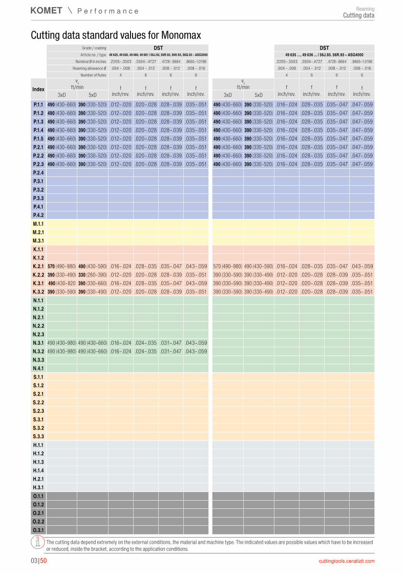
P.1.1 490 (430–660) 390 (330–520) .012–.020 .020–.028 .028–.039 .035–.051 490 (430–660) 390 (330–520) .016–.024 .028–.035 .035–.047 .047–.059P.1.2 490 (430–660) 390 (330–520) .012–.020 .020–.028 .028–.039 .035–.051 490 (430–660) 390 (330–520) .016–.024 .028–.035 .035–.047 .047–.059P.1.3 490 (430–660) 390 (330–520) .012–.020 .020–.028 .028–.039 .035–.051 490 (430–660) 390 (330–520) .016–.024 .028–.035 .035–.047 .047–.059P.1.4 490 (430–660) 390 (330–520) .012–.020 .020–.028 .028–.039 .035–.051 490 (430–660) 390 (330–520) .016–.024 .028–.035 .035–.047 .047–.059P.1.5 490 (430–660) 390 (330–520) .012–.020 .020–.028 .028–.039 .035–.051 490 (430–660) 390 (330–520) .016–.024 .028–.035 .035–.047 .047–.059P.2.1 490 (430–660) 390 (330–520) .012–.020 .020–.028 .028–.039 .035–.051 490 (430–660) 390 (330–520) .016–.024 .028–.035 .035–.047 .047–.059P.2.2 490 (430–660) 390 (330–520) .012–.020 .020–.028 .028–.039 .035–.051 490 (430–660) 390 (330–520) .016–.024 .028–.035 .035–.047 .047–.059P.2.3 490 (430–660) 390 (330–520) .012–.020 .020–.028 .028–.039 .035–.051 490 (430–660) 390 (330–520) .016–.024 .028–.035 .035–.047 .047–.059P.2.4P.3.1P.3.2P.3.3P.4.1P.4.2M.1.1M.2.1M.3.1K.1.1K.1.2K.2.1 570 (490–980) 490 (430–590) .016–.024 .028–.035 .035–.047 .043–.059 570 (490–980) 490 (430–590) .016–.024 .028–.035 .035–.047 .043–.059K.2.2 390 (330–490) 330 (260–390) .012–.020 .020–.028 .028–.039 .035–.051 390 (330–590) 390 (330–490) .012–.020 .020–.028 .028–.039 .035–.051K.3.1 490 (430–820 390 (330–660) .016–.024 .028–.035 .035–.047 .043–.059 390 (330–590) 390 (330–490) .012–.020 .020–.028 .028–.039 .035–.051K.3.2 390 (330–590) 390 (330–490) .012–.020 .020–.028 .028–.039 .035–.051 390 (330–590) 390 (330–490) .012–.020 .020–.028 .028–.039 .035–.051N.1.1N.1.2N.2.1N.2.2N.2.3N.3.1 490 (430–980) 490 (430–660) .016–.024 .024–.035 .031–.047 .043–.059N.3.2 490 (430–980) 490 (430–660) .016–.024 .024–.035 .031–.047 .043–.059N.3.3N.4.1S.1.1S.1.2S.2.1S.2.2S.2.3S.3.1S.3.2S.3.3H.1.1H.1.2H.1.3H.1.4H.2.1H.3.1O.1.1O.1.2O.2.1O.2.2O.3.1
03|50
Grade / coating DST DSTArticle no. / type 49 625, 49 626, 49 680, 49 681 / 56J.93, 56R.93, 56H.93, 56Q.93 – ASG3000 49 635 …, 49 636 ... / 56J.93. 56R.93 – ASG4000
Nominal Ø in inches .2205–.3503 .3504–.4727 .4728–.8664 .8665–1.0196 .2205–.3503 .3504–.4727 .4728–.8664 .8665–1.0196Reaming allowance Ø .004 – .008 .004 – .012 .008 – .012 .008 –. 016 .004 – .008 .004 – .012 .008 – .012 .008 –. 016
Number of flutes 4 6 6 6 4 6 6 6
Indexvc vc
ft/min f f f f ft/min f f f f3xD 5xD inch/rev. inch/rev. inch/rev. inch/rev. 3xD 5xD inch/rev. inch/rev. inch/rev. inch/rev.
Cutting data standard values for Monomax
The cutting data depend extremely on the external conditions, the material and machine type. The indicated values are possible values which have to be increased or reduced, inside the bracket, according to the application conditions.
ReamingCutting data
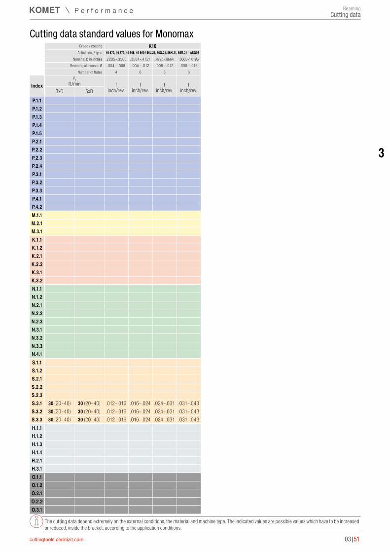
P.1.1P.1.2P.1.3P.1.4P.1.5P.2.1P.2.2P.2.3P.2.4P.3.1P.3.2P.3.3P.4.1P.4.2M.1.1M.2.1M.3.1K.1.1K.1.2K.2.1K.2.2K.3.1K.3.2N.1.1N.1.2N.2.1N.2.2N.2.3N.3.1N.3.2N.3.3N.4.1S.1.1S.1.2S.2.1S.2.2S.2.3S.3.1 30 (20–40) 30 (20–40) .012–.016 .016–.024 .024–.031 .031–.043S.3.2 30 (20–40) 30 (20–40) .012–.016 .016–.024 .024–.031 .031–.043S.3.3 30 (20–40) 30 (20–40) .012–.016 .016–.024 .024–.031 .031–.043H.1.1H.1.2H.1.3H.1.4H.2.1H.3.1O.1.1O.1.2O.2.1O.2.2O.3.1
03|51
3
Grade / coating K10Article no. / type 49 672, 49 673, 49 668, 49 669 / 56J.21, 56Q.21, 56H.21, 56R.21 – ASG03
Nominal Ø in inches .2205–.3503 .3504–.4727 .4728–.8664 .8665–1.0196Reaming allowance Ø .004 – .008 .004 – .012 .008 – .012 .008 –. 016
Number of flutes 4 6 6 6
Indexvc
ft/min f f f f3xD 5xD inch/rev. inch/rev. inch/rev. inch/rev.
Cutting data standard values for Monomax
The cutting data depend extremely on the external conditions, the material and machine type. The indicated values are possible values which have to be increased or reduced, inside the bracket, according to the application conditions.
ReamingCutting data

P.1.1 490 (430–660) 390 (330–520) .043–.067 .059–.091 .075–.110P.1.2 490 (430–660) 390 (330–520) .043–.067 .059–.091 .075–.110P.1.3 490 (430–660) 390 (330–520) .043–.067 .059–.091 .075–.110P.1.4 490 (430–660) 390 (330–520) .043–.067 .059–.091 .075–.110P.1.5 490 (430–660) 390 (330–520) .043–.067 .059–.091 .075–.110P.2.1 490 (430–660) 390 (330–520) .043–.067 .059–.091 .075–.110P.2.2 490 (430–660) 390 (330–520) .043–.067 .059–.091 .075–.110P.2.3 490 (430–660) 390 (330–520) .043–.067 .059–.091 .075–.110P.2.4 490 (430–660) 390 (330–520) .043–.067 .059–.091 .075–.110P.3.1 100 (80–160) 100 (80–130) .035–.051 .047–.071 .059–.091P.3.2 100 (80–160) 100 (80–130) .035–.051 .047–.071 .059–.091P.3.3 100 (80–160) 100 (80–130) .035–.051 .047–.071 .059–.091P.4.1 150 (110–200) 130 (110–160) .035–.051 .047–.071 .059–.091P.4.2 150 (110–200) 130 (110–160) .035–.051 .047–.071 .059–.091M.1.1 150 (110–200) 130 (110–160) .035–.051 .047–.071 .059–.091M.2.1 150 (110–200) 130 (110–160) .035–.051 .047–.071 .059–.091M.3.1 100 (80–160) 100 (80–130) .035–.051 .047–.071 .059–.091K.1.1 490 (430–720) 390 (330–490) .085–.080 .073–.107 .091–.134K.1.2 490 (430–720) 390 (330–490) .085–.080 .073–.107 .091–.134K.2.1 570 (490–980) 490 (430–590) .085–.080 .073–.107 .091–.134K.2.2 390 (330–590) 390 (330–490) .045–.066 .060–.088 .075–.110K.3.1 390 (330–590) 390 (330–490) .045–.066 .060–.088 .075–.110K.3.2 390 (330–590) 390 (330–490) .045–.066 .060–.088 .075–.110N.1.1N.1.2N.2.1N.2.2N.2.3N.3.1N.3.2N.3.3N.4.1S.1.1S.1.2S.2.1S.2.2S.2.3S.3.1S.3.2S.3.3H.1.1H.1.2H.1.3H.1.4H.2.1H.3.1O.1.1O.1.2O.2.1O.2.2O.3.1
03|52
Cutting Data Standard Values for Cutting Ring
The cutting data depend extremely on the external conditions, the material and machine type. The indicated values are possible values which have to be increased or reduced, inside the bracket, according to the application conditions.
Grade / coating DBG-P DBG-PArticle no. / type 49 836 … / 300.65 – ASG3000 49 835 … / 300.65 – ASG0106
Nominal Ø in inches 2.3858–3.1338 3.1339–3.9605 3.9606–4.3543 2.3858–3.1338 3.1339–3.9605 3.9606–4.3543Reaming allowance Ø .012 – .020 .012 – .020 .012 – .020 .012 – .020 .012 – .020 .012 – .020
Number of flutes 6 8 10 6 8 10
Indexvc vc
ft/min f f f ft/min f f f3xD 5xD inch/rev. inch/rev. inch/rev. 3xD 5xD inch/rev. inch/rev. inch/rev.
ReamingCutting data

P.1.1 330 (260–460) 260 (200–390) .043–.067 .059–.091 .075–.110P.1.2 330 (260–460) 260 (200–390) .043–.067 .059–.091 .075–.110P.1.3 330 (260–460) 260 (200–390) .043–.067 .059–.091 .075–.110P.1.4 330 (260–460) 260 (200–390) .043–.067 .059–.091 .075–.110P.1.5 330 (260–460) 260 (200–390) .043–.067 .059–.091 .075–.110P.2.1 330 (260–460) 260 (200–390) .043–.067 .059–.091 .075–.110P.2.2 330 (260–460) 260 (200–390) .043–.067 .059–.091 .075–.110P.2.3 330 (260–460) 260 (200–390) .043–.067 .059–.091 .075–.110P.2.4 330 (260–460) 260 (200–390) .043–.067 .059–.091 .075–.110P.3.1 100 (80–150) 100 (80–150) .031–.047 .043–.063 .051–.079P.3.2 100 (80–150) 100 (80–150) .031–.047 .043–.063 .051–.079P.3.3P.4.1 100 (80–150) 100 (80–150) .031–.047 .043–.063 .051–.079P.4.2 100 (80–150) 100 (80–150) .031–.047 .043–.063 .051–.079M.1.1 100 (80–150) 100 (80–130) .035–.051 .047–.071 .059–.091M.2.1 70 (50–110) 70 (50–110) .035–.051 .047–.071 .059–.091M.3.1 70 (50–110) 70 (50–110) .035–.051 .047–.071 .059–.091K.1.1 260 (200–430) 260 (200–390) .055–.079 .075–.079 .091–.134K.1.2 260 (200–430) 260 (200–390) .055–.079 .075–.079 .091–.134K.2.1K.2.2K.3.1K.3.2N.1.1N.1.2N.2.1N.2.2N.2.3N.3.1 390 (330–660) 390 (330–660) .047–.075 .067–.098 .083–.122N.3.2 390 (330–660) 390 (330–660) .039–.059 .055–.083 .067–.102N.3.3 260 (200–490) 260 (200–390) .039–.059 .055–.083 .067–.102N.4.1S.1.1S.1.2S.2.1S.2.2S.2.3S.3.1S.3.2S.3.3H.1.1H.1.2H.1.3H.1.4H.2.1H.3.1O.1.1O.1.2O.2.1O.2.2O.3.1
03|53
3
Cutting Data Standard Values for Cutting Ring
The cutting data depend extremely on the external conditions, the material and machine type. The indicated values are possible values which have to be increased or reduced, inside the bracket, according to the application conditions.
Grade / coating TiN TiNArticle no. / type 49 823 … / 300.05 – ASG3000 49 824 … / 300.05 – ASG0106
Nominal Ø in inches 2.3858–3.1338 3.1339–3.9605 3.9606–4.3543 2.3858–3.1338 3.1339–3.9605 3.9606–4.3543Reaming allowance Ø .012 – .020 .012 – .020 .012 – .020 .012 – .020 .012 – .020 .012 – .020
Number of flutes 6 8 10 6 8 10
Indexvc vc
ft/min f f f ft/min f f f3xD 5xD inch/rev. inch/rev. inch/rev. 3xD 5xD inch/rev. inch/rev. inch/rev.
ReamingCutting data
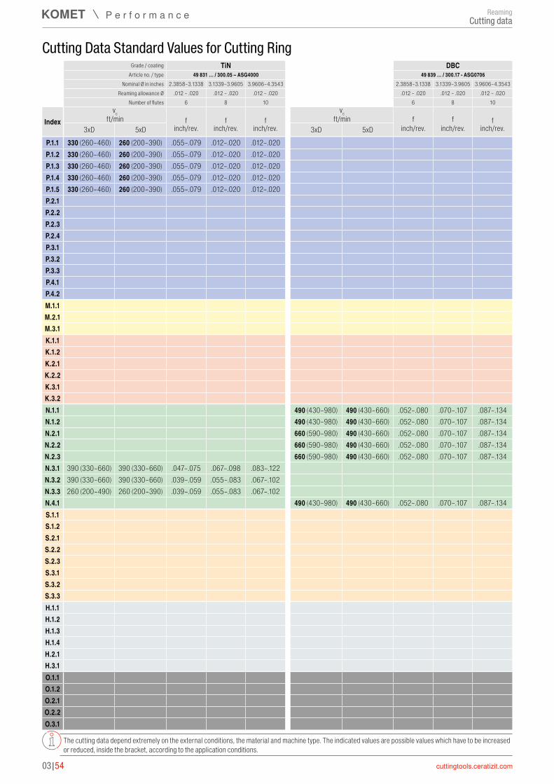
P.1.1 330 (260–460) 260 (200–390) .055–.079 .012–.020 .012–.020P.1.2 330 (260–460) 260 (200–390) .055–.079 .012–.020 .012–.020P.1.3 330 (260–460) 260 (200–390) .055–.079 .012–.020 .012–.020P.1.4 330 (260–460) 260 (200–390) .055–.079 .012–.020 .012–.020P.1.5 330 (260–460) 260 (200–390) .055–.079 .012–.020 .012–.020P.2.1P.2.2P.2.3P.2.4P.3.1P.3.2P.3.3P.4.1P.4.2M.1.1M.2.1M.3.1K.1.1K.1.2K.2.1K.2.2K.3.1K.3.2N.1.1 490 (430–980) 490 (430–660) .052–.080 .070–.107 .087–.134N.1.2 490 (430–980) 490 (430–660) .052–.080 .070–.107 .087–.134N.2.1 660 (590–980) 490 (430–660) .052–.080 .070–.107 .087–.134N.2.2 660 (590–980) 490 (430–660) .052–.080 .070–.107 .087–.134N.2.3 660 (590–980) 490 (430–660) .052–.080 .070–.107 .087–.134N.3.1 390 (330–660) 390 (330–660) .047–.075 .067–.098 .083–.122N.3.2 390 (330–660) 390 (330–660) .039–.059 .055–.083 .067–.102N.3.3 260 (200–490) 260 (200–390) .039–.059 .055–.083 .067–.102N.4.1 490 (430–980) 490 (430–660) .052–.080 .070–.107 .087–.134S.1.1S.1.2S.2.1S.2.2S.2.3S.3.1S.3.2S.3.3H.1.1H.1.2H.1.3H.1.4H.2.1H.3.1O.1.1O.1.2O.2.1O.2.2O.3.1
03|54
Cutting Data Standard Values for Cutting Ring
The cutting data depend extremely on the external conditions, the material and machine type. The indicated values are possible values which have to be increased or reduced, inside the bracket, according to the application conditions.
Grade / coating TiN DBCArticle no. / type 49 831 … / 300.05 – ASG4000 49 839 … / 300.17 - ASG0706
Nominal Ø in inches 2.3858–3.1338 3.1339–3.9605 3.9606–4.3543 2.3858–3.1338 3.1339–3.9605 3.9606–4.3543Reaming allowance Ø .012 – .020 .012 – .020 .012 – .020 .012 – .020 .012 – .020 .012 – .020
Number of flutes 6 8 10 6 8 10
Indexvc vc
ft/min f f f ft/min f f f3xD 5xD inch/rev. inch/rev. inch/rev. 3xD 5xD inch/rev. inch/rev. inch/rev.
ReamingCutting data
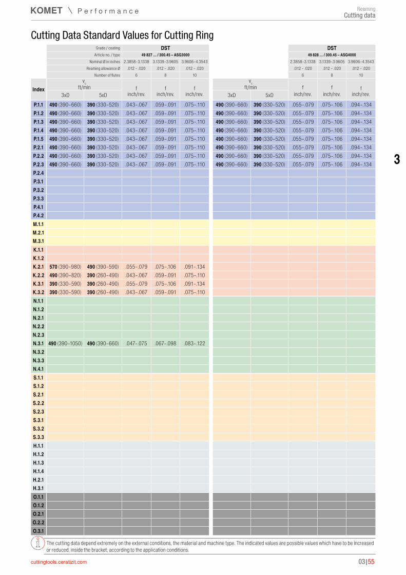
P.1.1 490 (390–660) 390 (330–520) .043–.067 .059–.091 .075–.110 490 (390–660) 390 (330–520) .055–.079 .075–.106 .094–.134P.1.2 490 (390–660) 390 (330–520) .043–.067 .059–.091 .075–.110 490 (390–660) 390 (330–520) .055–.079 .075–.106 .094–.134P.1.3 490 (390–660) 390 (330–520) .043–.067 .059–.091 .075–.110 490 (390–660) 390 (330–520) .055–.079 .075–.106 .094–.134P.1.4 490 (390–660) 390 (330–520) .043–.067 .059–.091 .075–.110 490 (390–660) 390 (330–520) .055–.079 .075–.106 .094–.134P.1.5 490 (390–660) 390 (330–520) .043–.067 .059–.091 .075–.110 490 (390–660) 390 (330–520) .055–.079 .075–.106 .094–.134P.2.1 490 (390–660) 390 (330–520) .043–.067 .059–.091 .075–.110 490 (390–660) 390 (330–520) .055–.079 .075–.106 .094–.134P.2.2 490 (390–660) 390 (330–520) .043–.067 .059–.091 .075–.110 490 (390–660) 390 (330–520) .055–.079 .075–.106 .094–.134P.2.3 490 (390–660) 390 (330–520) .043–.067 .059–.091 .075–.110 490 (390–660) 390 (330–520) .055–.079 .075–.106 .094–.134P.2.4P.3.1P.3.2P.3.3P.4.1P.4.2M.1.1M.2.1M.3.1K.1.1K.1.2K.2.1 570 (390–980) 490 (390–590) .055–.079 .075–.106 .091–.134K.2.2 490 (390–820) 390 (260–490) .043–.067 .059–.091 .075–.110K.3.1 390 (330–590) 390 (260–490) .055–.079 .075–.106 .091–.134K.3.2 390 (330–590) 390 (260–490) .043–.067 .059–.091 .075–.110N.1.1N.1.2N.2.1N.2.2N.2.3N.3.1 490 (390–1050) 490 (390–660) .047–.075 .067–.098 .083–.122N.3.2N.3.3N.4.1S.1.1S.1.2S.2.1S.2.2S.2.3S.3.1S.3.2S.3.3H.1.1H.1.2H.1.3H.1.4H.2.1H.3.1O.1.1O.1.2O.2.1O.2.2O.3.1
03|55
3
Cutting Data Standard Values for Cutting Ring
The cutting data depend extremely on the external conditions, the material and machine type. The indicated values are possible values which have to be increased or reduced, inside the bracket, according to the application conditions.
Grade / coating DST DSTArticle no. / type 49 827 … / 300.45 – ASG3000 49 828 … / 300.45 – ASG4000
Nominal Ø in inches 2.3858–3.1338 3.1339–3.9605 3.9606–4.3543 2.3858–3.1338 3.1339–3.9605 3.9606–4.3543Reaming allowance Ø .012 – .020 .012 – .020 .012 – .020 .012 – .020 .012 – .020 .012 – .020
Number of flutes 6 8 10 6 8 10
Indexvc vc
ft/min f f f ft/min f f f3xD 5xD inch/rev. inch/rev. inch/rev. 3xD 5xD inch/rev. inch/rev. inch/rev.
ReamingCutting data

P.1.1P.1.2P.1.3P.1.4P.1.5P.2.1P.2.2P.2.3P.2.4P.3.1P.3.2P.3.3P.4.1P.4.2M.1.1M.2.1M.3.1K.1.1K.1.2K.2.1K.2.2K.3.1K.3.2N.1.1N.1.2N.2.1N.2.2N.2.3N.3.1N.3.2N.3.3N.4.1S.1.1S.1.2S.2.1S.2.2S.2.3S.3.1 30 (20–40) 30 (20–40) .031–.043 .041–.057 .052–.072S.3.2 30 (20–40) 30 (20–40) .031–.043 .041–.057 .052–.072S.3.3 30 (20–40) 30 (20–40) .031–.043 .041–.057 .052–.072H.1.1H.1.2H.1.3H.1.4H.2.1H.3.1O.1.1O.1.2O.2.1O.2.2O.3.1
03|56
Cutting Data Standard Values for Cutting Ring
The cutting data depend extremely on the external conditions, the material and machine type. The indicated values are possible values which have to be increased or reduced, inside the bracket, according to the application conditions.
Grade / coating K10Article no. / type 49 832 … / 300.25 – ASG03
Nominal Ø in inches 2.3858–3.1338 3.1339–3.9605 3.9606–4.3543Reaming allowance Ø .012 – .020 .012 – .020 .012 – .020
Number of flutes 6 8 10
Indexvc
ft/min f f f3xD 5xD inch/rev. inch/rev. inch/rev.
ReamingCutting data
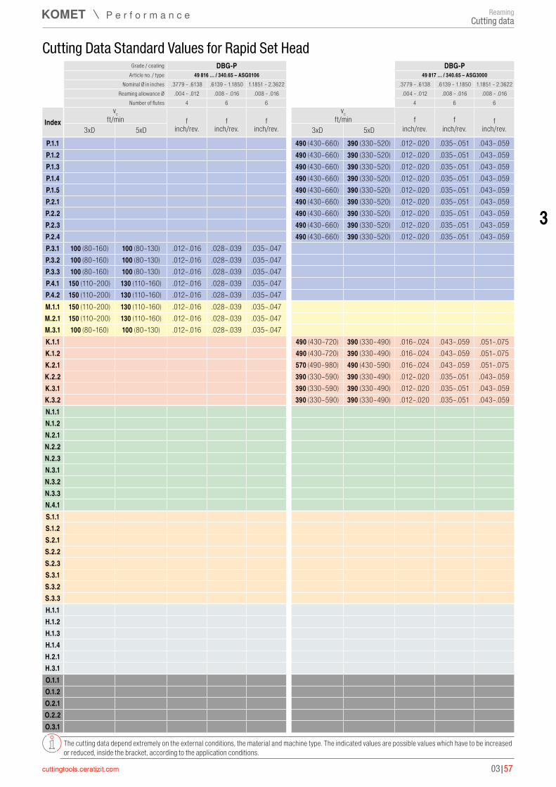
P.1.1 490 (430–660) 390 (330–520) .012–.020 .035–.051 .043–.059P.1.2 490 (430–660) 390 (330–520) .012–.020 .035–.051 .043–.059P.1.3 490 (430–660) 390 (330–520) .012–.020 .035–.051 .043–.059P.1.4 490 (430–660) 390 (330–520) .012–.020 .035–.051 .043–.059P.1.5 490 (430–660) 390 (330–520) .012–.020 .035–.051 .043–.059P.2.1 490 (430–660) 390 (330–520) .012–.020 .035–.051 .043–.059P.2.2 490 (430–660) 390 (330–520) .012–.020 .035–.051 .043–.059P.2.3 490 (430–660) 390 (330–520) .012–.020 .035–.051 .043–.059P.2.4 490 (430–660) 390 (330–520) .012–.020 .035–.051 .043–.059P.3.1 100 (80–160) 100 (80–130) .012–.016 .028–.039 .035–.047P.3.2 100 (80–160) 100 (80–130) .012–.016 .028–.039 .035–.047P.3.3 100 (80–160) 100 (80–130) .012–.016 .028–.039 .035–.047P.4.1 150 (110–200) 130 (110–160) .012–.016 .028–.039 .035–.047P.4.2 150 (110–200) 130 (110–160) .012–.016 .028–.039 .035–.047M.1.1 150 (110–200) 130 (110–160) .012–.016 .028–.039 .035–.047M.2.1 150 (110–200) 130 (110–160) .012–.016 .028–.039 .035–.047M.3.1 100 (80–160) 100 (80–130) .012–.016 .028–.039 .035–.047K.1.1 490 (430–720) 390 (330–490) .016–.024 .043–.059 .051–.075K.1.2 490 (430–720) 390 (330–490) .016–.024 .043–.059 .051–.075K.2.1 570 (490–980) 490 (430–590) .016–.024 .043–.059 .051–.075K.2.2 390 (330–590) 390 (330–490) .012–.020 .035–.051 .043–.059K.3.1 390 (330–590) 390 (330–490) .012–.020 .035–.051 .043–.059K.3.2 390 (330–590) 390 (330–490) .012–.020 .035–.051 .043–.059N.1.1N.1.2N.2.1N.2.2N.2.3N.3.1N.3.2N.3.3N.4.1S.1.1S.1.2S.2.1S.2.2S.2.3S.3.1S.3.2S.3.3H.1.1H.1.2H.1.3H.1.4H.2.1H.3.1O.1.1O.1.2O.2.1O.2.2O.3.1
03|57
3
Cutting Data Standard Values for Rapid Set Head
The cutting data depend extremely on the external conditions, the material and machine type. The indicated values are possible values which have to be increased or reduced, inside the bracket, according to the application conditions.
Grade / coating DBG-P DBG-PArticle no. / type 49 816 … / 340.65 – ASG0106 49 817 … / 340.65 – ASG3000
Nominal Ø in inches .3779 – .6138 .6139 – 1.1850 1.1851 – 2.3622 .3779 – .6138 .6139 – 1.1850 1.1851 – 2.3622Reaming allowance Ø .004 – .012 .008 – .016 .008 – .016 .004 – .012 .008 – .016 .008 – .016
Number of flutes 4 6 6 4 6 6
Indexvc vc
ft/min f f f ft/min f f f3xD 5xD inch/rev. inch/rev. inch/rev. 3xD 5xD inch/rev. inch/rev. inch/rev.
ReamingCutting data
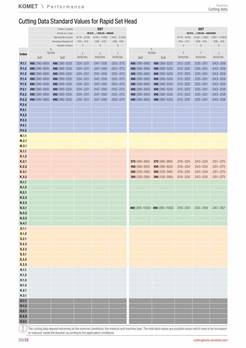
P.1.1 490 (390–660) 490 (390–520) .024–.031 .047–.059 .055–.075 490 (390–660) 490 (390–520) .012–.020 .035–.051 .043–.059P.1.2 490 (390–660) 490 (390–520) .024–.031 .047–.059 .055–.075 490 (390–660) 490 (390–520) .012–.020 .035–.051 .043–.059P.1.3 490 (390–660) 490 (390–520) .024–.031 .047–.059 .055–.075 490 (390–660) 490 (390–520) .012–.020 .035–.051 .043–.059P.1.4 490 (390–660) 490 (390–520) .024–.031 .047–.059 .055–.075 490 (390–660) 490 (390–520) .012–.020 .035–.051 .043–.059P.1.5 490 (390–660) 490 (390–520) .024–.031 .047–.059 .055–.075 490 (390–660) 490 (390–520) .012–.020 .035–.051 .043–.059P.2.1 490 (390–660) 490 (390–520) .024–.031 .047–.059 .055–.075 490 (390–660) 490 (390–520) .012–.020 .035–.051 .043–.059P.2.2 490 (390–660) 490 (390–520) .024–.031 .047–.059 .055–.075 490 (390–660) 490 (390–520) .012–.020 .035–.051 .043–.059P.2.3 490 (390–660) 490 (390–520) .024–.031 .047–.059 .055–.075 490 (390–660) 490 (390–520) .012–.020 .035–.051 .043–.059P.2.4P.3.1P.3.2P.3.3P.4.1P.4.2M.1.1M.2.1M.3.1K.1.1K.1.2K.2.1 570 (490–980) 570 (490–980) .016–.024 .043–.024 .051–.075K.2.2 490 (390–820) 490 (390–820) .016–.024 .043–.024 .051–.075K.3.1 390 (330–590) 390 (330–590) .016–.024 .043–.024 .051–.075K.3.2 390 (330–590) 390 (330–590) .016–.024 .043–.024 .051–.075N.1.1N.1.2N.2.1N.2.2N.2.3N.3.1 490 (390–1050) 490 (390–1050) .016–.024 .043–.059 .047–.067N.3.2N.3.3N.4.1S.1.1S.1.2S.2.1S.2.2S.2.3S.3.1S.3.2S.3.3H.1.1H.1.2H.1.3H.1.4H.2.1H.3.1O.1.1O.1.2O.2.1O.2.2O.3.1
03|58
Cutting Data Standard Values for Rapid Set Head
The cutting data depend extremely on the external conditions, the material and machine type. The indicated values are possible values which have to be increased or reduced, inside the bracket, according to the application conditions.
Grade / coating DST DSTArticle no. / type 49 812 … / 340.92 – ASG05 49 813 … / 340.93 – ASG3000
Nominal Ø in inches .3779 – .6138 .6139 – 1.1850 1.1851 – 2.3622 .3779 – .6138 .6139 – 1.1850 1.1851 – 2.3622Reaming allowance Ø .004 – .012 .008 – .016 .008 – .016 .004 – .012 .008 – .016 .008 – .016
Number of flutes 4 6 6 4 6 6
Indexvc vc
ft/min f f f ft/min f f f3xD 5xD inch/rev. inch/rev. inch/rev. 3xD 5xD inch/rev. inch/rev. inch/rev.
ReamingCutting data

P.1.1 330 (260–460) 260 (200–390) .024–.031 .047–.059 .055–.075 330 (260–460) 260 (200–390) .012–.020 .035–.051 .043–.059P.1.2 330 (260–460) 260 (200–390) .024–.031 .047–.059 .055–.075 330 (260–460) 260 (200–390) .012–.020 .035–.051 .043–.059P.1.3 330 (260–460) 260 (200–390) .024–.031 .047–.059 .055–.075 330 (260–460) 260 (200–390) .012–.020 .035–.051 .043–.059P.1.4 330 (260–460) 260 (200–390) .024–.031 .047–.059 .055–.075 330 (260–460) 260 (200–390) .012–.020 .035–.051 .043–.059P.1.5 330 (260–460) 260 (200–390) .024–.031 .047–.059 .055–.075 330 (260–460) 260 (200–390) .012–.020 .035–.051 .043–.059P.2.1 330 (260–460) 260 (200–390) .024–.031 .047–.059 .055–.075 330 (260–460) 260 (200–390) .012–.020 .035–.051 .043–.059P.2.2 330 (260–460) 260 (200–390) .024–.031 .047–.059 .055–.075 330 (260–460) 260 (200–390) .012–.020 .035–.051 .043–.059P.2.3 330 (260–460) 260 (200–390) .024–.031 .047–.059 .055–.075 330 (260–460) 260 (200–390) .012–.020 .035–.051 .043–.059P.2.4 330 (260–460) 260 (200–390) .024–.031 .047–.059 .055–.075 330 (260–460) 260 (200–390) .012–.020 .035–.051 .043–.059P.3.1P.3.2P.3.3P.4.1P.4.2M.1.1M.2.1M.3.1K.1.1 260 (200–430) 260 (200–390) .016–.024 .043–.059 .051–.075K.1.2 260 (200–430) 260 (200–390) .016–.024 .043–.059 .051–.075K.2.1K.2.2K.3.1K.3.2N.1.1N.1.2N.2.1N.2.2N.2.3N.3.1 390 (330–660) 390 (330–660) .016–.024 .043–.059 .047–.067N.3.2 260 (200–490) 260 (200–490) .012–.020 .035–.051 .039–.055N.3.3 260 (200–490) 260 (200–490) .012–.020 .035–.051 .039–.055N.4.1S.1.1S.1.2S.2.1S.2.2S.2.3S.3.1S.3.2S.3.3H.1.1H.1.2H.1.3H.1.4H.2.1H.3.1O.1.1O.1.2O.2.1O.2.2O.3.1
03|59
3
Cutting Data Standard Values for Rapid Set Head
The cutting data depend extremely on the external conditions, the material and machine type. The indicated values are possible values which have to be increased or reduced, inside the bracket, according to the application conditions.
Grade / coating TiN TiNArticle no. / type 49 805 … / 340.70 – ASG05 49 808 … / 340.71 – ASG3000
Nominal Ø in inches .3779 – .6138 .6139 – 1.1850 1.1851 – 2.3622 .3779 – .6138 .6139 – 1.1850 1.1851 – 2.3622Reaming allowance Ø .004 – .012 .008 – .016 .008 – .016 .004 – .012 .008 – .016 .008 – .016
Number of flutes 4 6 6 4 6 6
Indexvc vc
ft/min f f f ft/min f f f3xD 5xD inch/rev. inch/rev. inch/rev. 3xD 5xD inch/rev. inch/rev. inch/rev.
ReamingCutting data
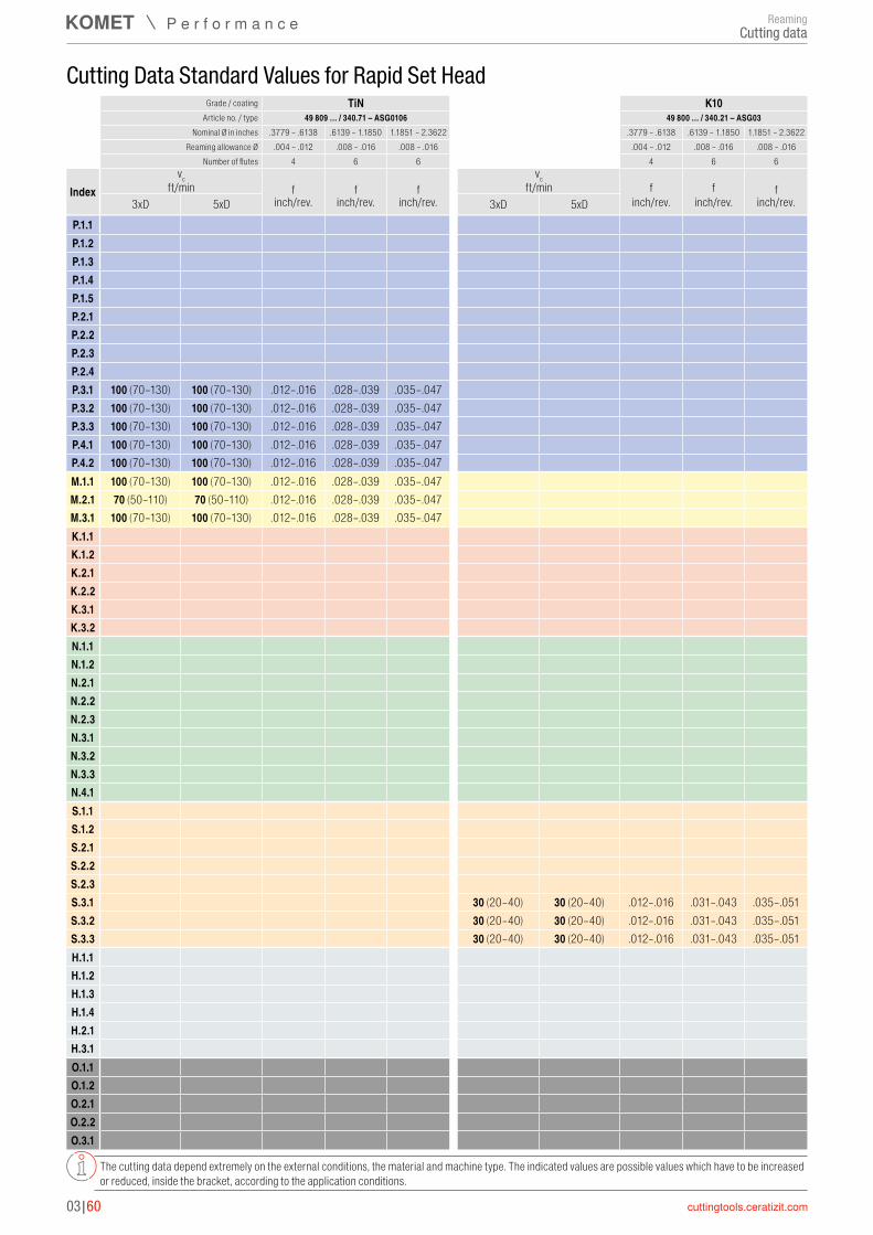
P.1.1P.1.2P.1.3P.1.4P.1.5P.2.1P.2.2P.2.3P.2.4P.3.1 100 (70–130) 100 (70–130) .012–.016 .028–.039 .035–.047P.3.2 100 (70–130) 100 (70–130) .012–.016 .028–.039 .035–.047P.3.3 100 (70–130) 100 (70–130) .012–.016 .028–.039 .035–.047P.4.1 100 (70–130) 100 (70–130) .012–.016 .028–.039 .035–.047P.4.2 100 (70–130) 100 (70–130) .012–.016 .028–.039 .035–.047M.1.1 100 (70–130) 100 (70–130) .012–.016 .028–.039 .035–.047M.2.1 70 (50–110) 70 (50–110) .012–.016 .028–.039 .035–.047M.3.1 100 (70–130) 100 (70–130) .012–.016 .028–.039 .035–.047K.1.1K.1.2K.2.1K.2.2K.3.1K.3.2N.1.1N.1.2N.2.1N.2.2N.2.3N.3.1N.3.2N.3.3N.4.1S.1.1S.1.2S.2.1S.2.2S.2.3S.3.1 30 (20–40) 30 (20–40) .012–.016 .031–.043 .035–.051S.3.2 30 (20–40) 30 (20–40) .012–.016 .031–.043 .035–.051S.3.3 30 (20–40) 30 (20–40) .012–.016 .031–.043 .035–.051H.1.1H.1.2H.1.3H.1.4H.2.1H.3.1O.1.1O.1.2O.2.1O.2.2O.3.1
03|60
Cutting Data Standard Values for Rapid Set Head
The cutting data depend extremely on the external conditions, the material and machine type. The indicated values are possible values which have to be increased or reduced, inside the bracket, according to the application conditions.
Grade / coating TiN K10Article no. / type 49 809 … / 340.71 – ASG0106 49 800 … / 340.21 – ASG03
Nominal Ø in inches .3779 – .6138 .6139 – 1.1850 1.1851 – 2.3622 .3779 – .6138 .6139 – 1.1850 1.1851 – 2.3622Reaming allowance Ø .004 – .012 .008 – .016 .008 – .016 .004 – .012 .008 – .016 .008 – .016
Number of flutes 4 6 6 4 6 6
Indexvc vc
ft/min f f f ft/min f f f3xD 5xD inch/rev. inch/rev. inch/rev. 3xD 5xD inch/rev. inch/rev. inch/rev.
ReamingCutting data

P.1.1 30 (20–30) 30 (20–30) .012–.020 .035–.051 .043–.059P.1.2 100 (50–150) 100 (50–150) .012–.020 .035–.051 .043–.059P.1.3 30 (20–30) 30 (20–30) .012–.020 .035–.051 .043–.059P.1.4 30 (20–30) 30 (20–30) .012–.020 .035–.051 .043–.059P.1.5 30 (20–30) 30 (20–30) .012–.020 .035–.051 .043–.059P.2.1 30 (20–30) 30 (20–30) .012–.020 .035–.051 .043–.059P.2.2 30 (20–30) 30 (20–30) .012–.020 .035–.051 .043–.059P.2.3 30 (20–30) 30 (20–30) .012–.020 .035–.051 .043–.059P.2.4P.3.1P.3.2P.3.3P.4.1P.4.2M.1.1M.2.1M.3.1K.1.1 50 (40–80) 50 (40–80) .016–.024 .043–.059 .051–.075K.1.2 50 (40–80) 50 (40–80) .016–.024 .043–.059 .051–.075K.2.1 40 (30–60) 40 (30–60) .016–.024 .043–.059 .051–.075K.2.2 40 (30–50) 40 (30–50) .012–.020 .035–.051 .043–.059K.3.1 40 (30–60) 40 (30–60) .012–.020 .035–.051 .043–.059K.3.2 40 (30–60) 40 (30–60) .012–.020 .035–.051 .043–.059N.1.1 50 (30–100) 50 (30–100) .012–.020 .035–.051 .043–.059 50 (40–100) 50 (40–100) .012–.020 .035–.051 .043–.059N.1.2 50 (30–100) 50 (30–100) .012–.020 .035–.051 .043–.059 50 (40–100) 50 (40–100) .012–.020 .035–.051 .043–.059N.2.1 40 (30–70) 12 (10–20) .016–.024 .043–.059 .047–.075 50 (40–100) 50 (40–100) .016–.024 .043–.059 .047–.075N.2.2 40 (30–70) 40 (30–70) .016–.024 .043–.059 .047–.075 50 (40–100) 50 (40–100) .016–.024 .043–.059 .047–.075N.2.3 40 (30–70) 40 (30–70) .016–.024 .043–.059 .047–.075 40 (30–70) 40 (30–70) .016–.024 .043–.059 .047–.075N.3.1 50 (30–100) 50 (30–100) .016–.024 .043–.059 .047–.075 50 (40–100) 50 (40–100) .016–.024 .043–.059 .047–.067N.3.2 50 (30–100) 50 (30–100) .016–.024 .043–.059 .047–.075 40 (30–70) 40 (30–70) .012–.020 .035–.051 .039–.055N.3.3 40 (30–70) 40 (30–70) .012–.020 .035–.051 .039–.055 40 (30–70) 40 (30–70) .012–.020 .035–.051 .039–.055N.4.1 50 (30–100) 50 (30–100) .016–.024 .043–.059 .047–.075 50 (40–100) 50 (40–100) .016–.024 .043–.059 .047–.075S.1.1S.1.2S.2.1S.2.2S.2.3S.3.1S.3.2S.3.3H.1.1H.1.2H.1.3H.1.4H.2.1H.3.1O.1.1O.1.2O.2.1O.2.2O.3.1
03|61
3
Cutting Data Standard Values for Rapid Set Head
The cutting data depend extremely on the external conditions, the material and machine type. The indicated values are possible values which have to be increased or reduced, inside the bracket, according to the application conditions.
Grade / coating K10 K10Article no. / type 49 804 … / 340.21 – ASG02 49 801 … / 340.21 – ASG3000
Nominal Ø in inches .3779 – .6138 .6139 – 1.1850 1.1851 – 2.3622 .3779 – .6138 .6139 – 1.1850 1.1851 – 2.3622Reaming allowance Ø .004 – .012 .008 – .016 .008 – .016 .004 – .012 .008 – .016 .008 – .016
Number of flutes 4 6 6 4 6 6
Indexvc vc
ft/min f f f ft/min f f f3xD 5xD inch/rev. inch/rev. inch/rev. 3xD 5xD inch/rev. inch/rev. inch/rev.
ReamingCutting data
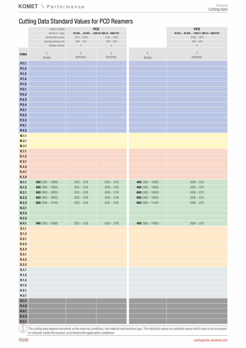
P.1.1P.1.2P.1.3P.1.4P.1.5P.2.1P.2.2P.2.3P.2.4P.3.1P.3.2P.3.3P.4.1P.4.2M.1.1M.2.1M.3.1K.1.1K.1.2K.2.1K.2.2K.3.1K.3.2N.1.1 490 (360 – 1080) .005 – .016 .005 – .016 490 (360 – 1080) .009 – .031N.1.2 490 (360 – 1080) .005 – .016 .005 – .016 490 (360 – 1080) .009 – .031N.2.1 660 (360 – 1800) .005 – .016 .005 – .016 660 (360 – 1800) .009 – .031N.2.2 660 (360 – 1800) .005 – .016 .005 – .016 660 (360 – 1800) .009 – .031N.2.3 660 (360 – 1440) .005 – .016 .005 – .016 660 (360 – 1440) .009 – .031N.3.1N.3.2N.3.3N.4.1 490 (360 – 1080) .005 – .016 .005 – .016 490 (360 – 1080) .009 – .031S.1.1S.1.2S.2.1S.2.2S.2.3S.3.1S.3.2S.3.3H.1.1H.1.2H.1.3H.1.4H.2.1H.3.1O.1.1O.1.2O.2.1O.2.2O.3.1
03|62
Cutting Data Standard Values for PCD Reamers
The cutting data depend extremely on the external conditions, the material and machine type. The indicated values are possible values which have to be increased or reduced, inside the bracket, according to the application conditions.
Grade / coating PCD PCDArticle no. / type 49 200 ..., 49 204 … / 690.10, 690.13 – ASG1101 49 201..., 49 205 … / 690.11, 690.14 – ASG1101
Nominal Ø in inches .1575 – .3150 .3151 – .7913 .3780 – .7913Reaming allowance Ø .004 – .012 .004 – .016 .004 – .016
Number of flutes 2 2 4
Index vc f f vc fft/min inch/rev. inch/rev. ft/min inch/rev.
ReamingCutting data

3
03|63
REAMAX TS – Assembly instructions
M Ø Range
Tightening torque (M)
.7087 – .7873 13 in-lbs
.7874 – .8661 22 in-lbs
.8662 – 1.0629 35 in-lbs
1.0630 – 1.3779 44 in-lbs
1.3780 – 1.6535 53 in-lbs
1.6536 – 2.0472 89 in-lbs
2.0473 – 2.7560 115 in-lbs
Clean the Morse taper adapter/face contact → grease-free. Screw the pull stud (5) into the reaming head and tighten using the open-ended spanner (6).
Use the key (3) to close the jaws (2), observe the recommended tightening torque. When inserting the reaming head (1), this is pulled into its final position when the jaws (2) are closed.
Expansion for wear compensation: The smallest drilling tolerances up to IT4 can be achieved through adjustment with the hex key (4).
Use key (3) to open jaws (2), but do not fully release, and insert reaming head (1).
When removing the reamer head (1), it is pressed out of its position by the jaws (2) and can thus be easily removed from the holder: Use key (3) to open the jaws (2) but do not fully release, and remove reamer head (1).
1
1
1
4
2
2
2
3
5
6
3
3
Technical InformationReaming
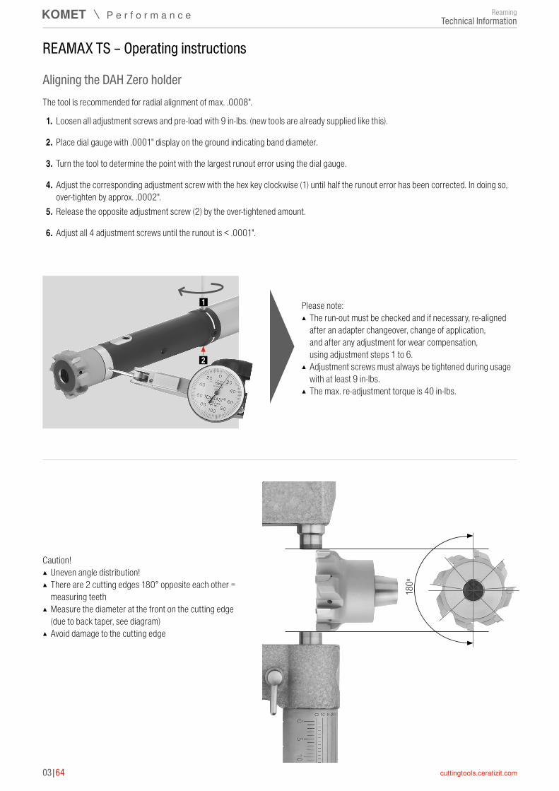
03|64
REAMAX TS – Operating instructions
Aligning the DAH Zero holder
180 º
Caution! ▲ Uneven angle distribution! ▲ There are 2 cutting edges 180° opposite each other = measuring teeth
▲ Measure the diameter at the front on the cutting edge (due to back taper, see diagram)
▲ Avoid damage to the cutting edge
Please note: ▲ The run-out must be checked and if necessary, re-aligned after an adapter changeover, change of application, and after any adjustment for wear compensation, using adjustment steps 1 to 6.
▲ Adjustment screws must always be tightened during usage with at least 9 in-lbs.
▲ The max. re-adjustment torque is 40 in-lbs.
1
2
The tool is recommended for radial alignment of max. .0008".
1. Loosen all adjustment screws and pre-load with 9 in-lbs. (new tools are already supplied like this).
2. Place dial gauge with .0001" display on the ground indicating band diameter.
3. Turn the tool to determine the point with the largest runout error using the dial gauge.
4. Adjust the corresponding adjustment screw with the hex key clockwise (1) until half the runout error has been corrected. In doing so, over-tighten by approx. .0002".
5. Release the opposite adjustment screw (2) by the over-tightened amount.
6. Adjust all 4 adjustment screws until the runout is < .0001".
Technical InformationReaming

3
03|65
Rapid Set Head – Assembly instructions
M
Each rapid set head is delivered with slightly greased taper.Do not wipe off!Taper must be slightly greased with copper grease!Clean taper in holder thoroughly → free of grease.Turn the differential screw one rotation into the head (counter-clockwise thread).
Before tightening turn the drive keys of the rapid set head against the direction of machining until it hits the holder.
Tightening the left-/right screw. Observe the specified tightening torque M in the index table.
Ø range Tightening torque (M)
0.496 – 0.614 6 – 8 in-lbs
0.615 – 0.732 10 – 12 in-lbs
0.733 – 0.945 16 – 20 in-lbs
0.946 – 1.575 27 – 34 in-lbs
1.576 – 2.362 46 – 58 in-lbs
Rapid set heads up to diameter 0.496" are assembled with a clamping screw at the back of the holder. The screw has a counter-clockwise thread.
Technical InformationReaming
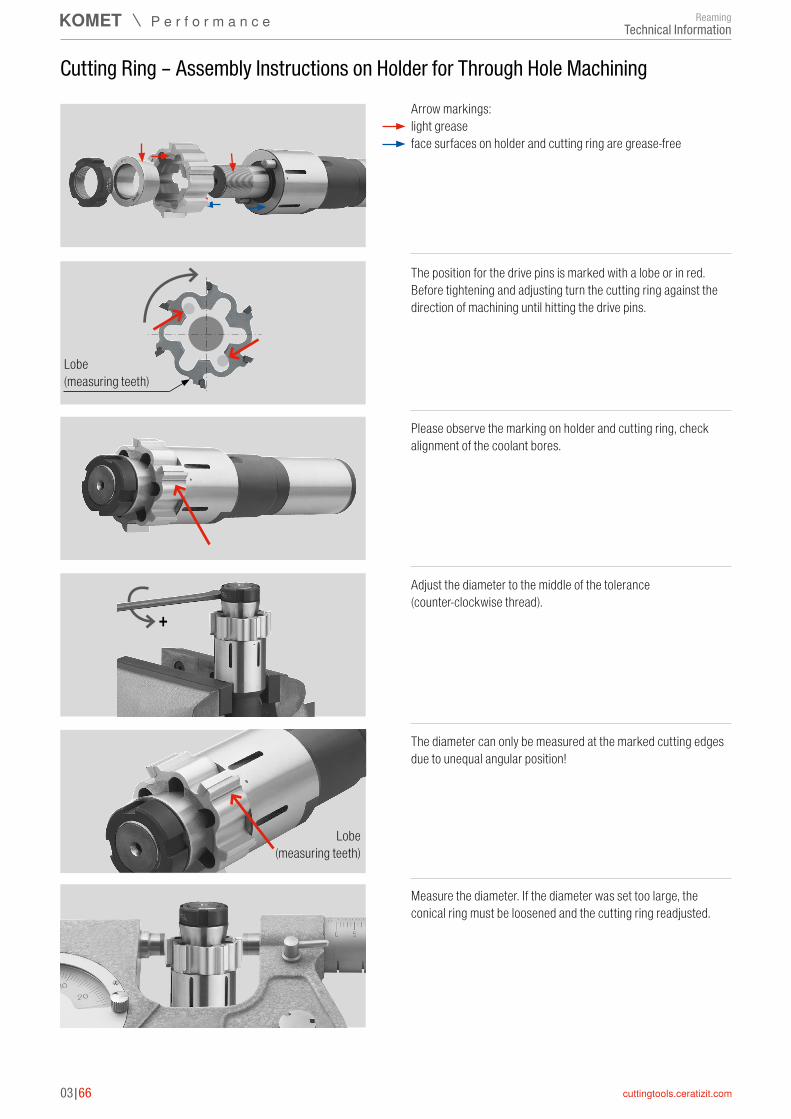
03|66
+
Arrow markings: light grease face surfaces on holder and cutting ring are grease-free
Cutting Ring – Assembly Instructions on Holder for Through Hole Machining
The position for the drive pins is marked with a lobe or in red. Before tightening and adjusting turn the cutting ring against the direction of machining until hitting the drive pins.
Lobe (measuring teeth)
Please observe the marking on holder and cutting ring, check alignment of the coolant bores.
Adjust the diameter to the middle of the tolerance (counter-clockwise thread).
The diameter can only be measured at the marked cutting edges due to unequal angular position!
Lobe (measuring teeth)
Measure the diameter. If the diameter was set too large, the conical ring must be loosened and the cutting ring readjusted.
Technical InformationReaming
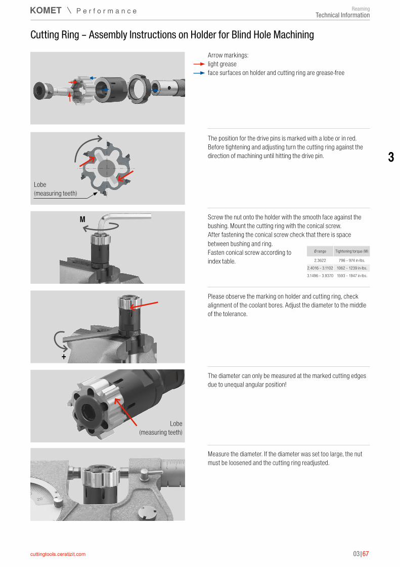
3
03|67
+
Arrow markings: light grease face surfaces on holder and cutting ring are grease-free
Cutting Ring – Assembly Instructions on Holder for Blind Hole Machining
The position for the drive pins is marked with a lobe or in red. Before tightening and adjusting turn the cutting ring against the direction of machining until hitting the drive pin.
Lobe (measuring teeth)
Screw the nut onto the holder with the smooth face against the bushing. Mount the cutting ring with the conical screw. After fastening the conical screw check that there is space
Please observe the marking on holder and cutting ring, check alignment of the coolant bores. Adjust the diameter to the middle of the tolerance.
The diameter can only be measured at the marked cutting edges due to unequal angular position!
Lobe (measuring teeth)
Measure the diameter. If the diameter was set too large, the nut must be loosened and the cutting ring readjusted.
M
Ø range Tightening torque (M)
2.3622 796 – 974 in-lbs.
2.4016 – 3.1102 1062 – 1239 in-lbs.
3.1496 – 3.9370 1593 – 1947 in-lbs.
between bushing and ring. Fasten conical screw according to index table.
Technical InformationReaming
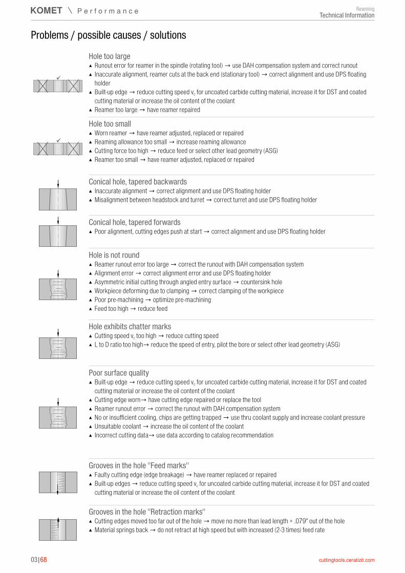
03|68
Hole too large ▲ Runout error for reamer in the spindle (rotating tool) → use DAH compensation system and correct runout ▲ Inaccurate alignment, reamer cuts at the back end (stationary tool) → correct alignment and use DPS floating holder
▲ Built-up edge → reduce cutting speed vc for uncoated carbide cutting material, increase it for DST and coated cutting material or increase the oil content of the coolant
▲ Reamer too large → have reamer repaired
Hole too small ▲ Worn reamer → have reamer adjusted, replaced or repaired ▲ Reaming allowance too small → increase reaming allowance ▲ Cutting force too high → reduce feed or select other lead geometry (ASG) ▲ Reamer too small → have reamer adjusted, replaced or repaired
Conical hole, tapered backwards ▲ Inaccurate alignment → correct alignment and use DPS floating holder ▲ Misalignment between headstock and turret → correct turret and use DPS floating holder
Conical hole, tapered forwards ▲ Poor alignment, cutting edges push at start → correct alignment and use DPS floating holder
Hole is not round ▲ Reamer runout error too large → correct the runout with DAH compensation system ▲ Alignment error → correct alignment error and use DPS floating holder ▲ Asymmetric initial cutting through angled entry surface → countersink hole ▲ Workpiece deforming due to clamping → correct clamping of the workpiece ▲ Poor pre-machining → optimize pre-machining ▲ Feed too high → reduce feed
Hole exhibits chatter marks ▲ Cutting speed vc too high → reduce cutting speed ▲ L to D ratio too high→ reduce the speed of entry, pilot the bore or select other lead geometry (ASG)
Poor surface quality ▲ Built-up edge → reduce cutting speed vc for uncoated carbide cutting material, increase it for DST and coated cutting material or increase the oil content of the coolant
▲ Cutting edge worn→ have cutting edge repaired or replace the tool ▲ Reamer runout error → correct the runout with DAH compensation system ▲ No or insufficient cooling, chips are getting trapped → use thru coolant supply and increase coolant pressure ▲ Unsuitable coolant → increase the oil content of the coolant ▲ Incorrect cutting data→ use data according to catalog recommendation
Grooves in the hole "Feed marks" ▲ Faulty cutting edge (edge breakage) → have reamer replaced or repaired ▲ Built-up edges → reduce cutting speed vc for uncoated carbide cutting material, increase it for DST and coated cutting material or increase the oil content of the coolant
Grooves in the hole "Retraction marks" ▲ Cutting edges moved too far out of the hole → move no more than lead length + .079" out of the hole ▲ Material springs back → do not retract at high speed but with increased (2-3 times) feed rate
Problems / possible causes / solutions
ReamingTechnical Information
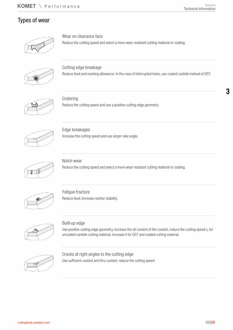
03|69
3
Wear on clearance faceReduce the cutting speed and select a more wear resistant cutting material or coating.
Cutting edge breakageReduce feed and reaming allowance. In the case of interrupted holes, use coated carbide instead of DST.
CrateringReduce the cutting speed and use a positive cutting edge geometry.
Edge breakagesIncrease the cutting speed and use larger rake angle.
Notch wearReduce the cutting speed and select a more wear resistant cutting material or coating.
Fatigue fractureReduce feed, increase reamer stability.
Built-up edgeUse positive cutting edge geometry, increase the oil content of the coolant, reduce the cutting speed vc for uncoated carbide cutting material, increase it for DST and coated cutting material.
Cracks at right angles to the cutting edgeUse sufficient coolant and thru coolant, reduce the cutting speed.
Types of wear
ReamingTechnical Information
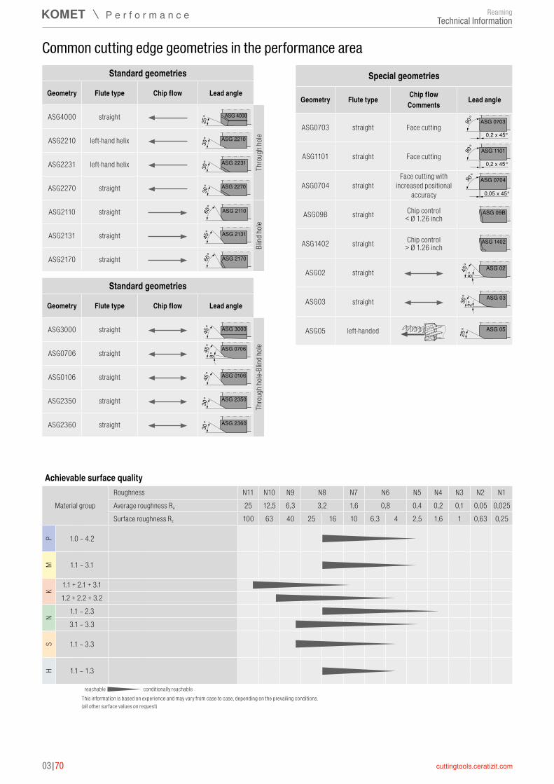
03|70
Common cutting edge geometries in the performance areaStandard geometries
Geometry Flute type Chip flow Lead angle
ASG4000 straight ASG 4000
25°
Thro
ugh h
oleASG2210 left-hand helix ASG 2210
30°
ASG2231 left-hand helix ASG 2231
30°
ASG2270 straight ASG 2270
30°
ASG2110 straight ASG 211060°
Blind
hole
ASG2131 straight ASG 213145°
ASG2170 straight ASG 217060°
Standard geometries
Geometry Flute type Chip flow Lead angle
ASG3000 straight ASG 300045°
Thro
ugh h
ole-B
lind h
oleASG0706 straight ASG 070645°
8°
ASG0106 straight ASG 010645°
ASG2350 straight ASG 2350
30°
ASG2360 straight ASG 2360
30°
Special geometries
Geometry Flute type Chip flow Lead angleComments
ASG0703 straight Face cuttingASG 0703
0,2 x 45°
90°
ASG1101 straight Face cuttingASG 1101
0,2 x 45°
90°
ASG0704 straightFace cutting with
increased positional accuracy
ASG 0704
0,05 x 45°
90°
ASG09B straight Chip control ASG 09B< Ø 1.26 inch
ASG1402 straight Chip control ASG 1402> Ø 1.26 inch
ASG02 straight ASG 0245°
8°
ASG03 straight ASG 03
30°
2°
ASG05 left-handed ASG 05
25°
Achievable surface quality
Material groupRoughness N11 N10 N9 N8 N7 N6 N5 N4 N3 N2 N1Average roughness Ra 25 12,5 6,3 3,2 1,6 0,8 0,4 0,2 0,1 0,05 0,025Surface roughness Rz 100 63 40 25 16 10 6,3 4 2,5 1,6 1 0,63 0,25
P 1.0 – 4.2
M 1.1 – 3.1
K
1.1 + 2.1 + 3.11.2 + 2.2 + 3.2
N
1.1 – 2.33.1 – 3.3
S 1.1 – 3.3
H 1.1 – 1.3
reachable conditionally reachableThis information is based on experience and may vary from case to case, depending on the prevailing conditions.(all other surface values on request)
Technical InformationReaming
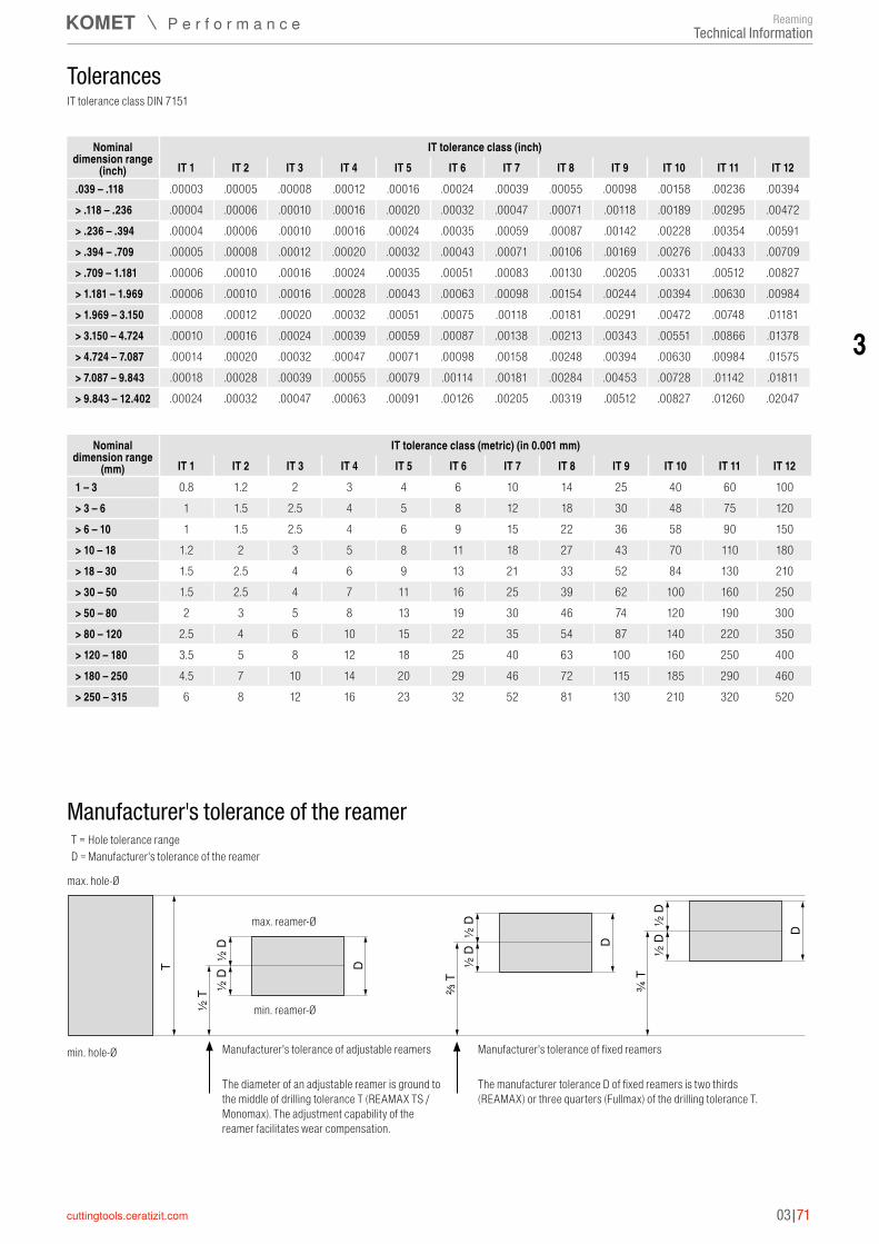
3
03|71
Tolerances
Nominal dimension range
(mm)
IT tolerance class (metric) (in 0.001 mm)IT 1 IT 2 IT 3 IT 4 IT 5 IT 6 IT 7 IT 8 IT 9 IT 10 IT 11 IT 12
1 – 3 0.8 1.2 2 3 4 6 10 14 25 40 60 100> 3 – 6 1 1.5 2.5 4 5 8 12 18 30 48 75 120> 6 – 10 1 1.5 2.5 4 6 9 15 22 36 58 90 150> 10 – 18 1.2 2 3 5 8 11 18 27 43 70 110 180> 18 – 30 1.5 2.5 4 6 9 13 21 33 52 84 130 210> 30 – 50 1.5 2.5 4 7 11 16 25 39 62 100 160 250> 50 – 80 2 3 5 8 13 19 30 46 74 120 190 300> 80 – 120 2.5 4 6 10 15 22 35 54 87 140 220 350> 120 – 180 3.5 5 8 12 18 25 40 63 100 160 250 400> 180 – 250 4.5 7 10 14 20 29 46 72 115 185 290 460> 250 – 315 6 8 12 16 23 32 52 81 130 210 320 520
Nominal dimension range
(inch)
IT tolerance class (inch)IT 1 IT 2 IT 3 IT 4 IT 5 IT 6 IT 7 IT 8 IT 9 IT 10 IT 11 IT 12
.039 – .118 .00003 .00005 .00008 .00012 .00016 .00024 .00039 .00055 .00098 .00158 .00236 .00394> .118 – .236 .00004 .00006 .00010 .00016 .00020 .00032 .00047 .00071 .00118 .00189 .00295 .00472> .236 – .394 .00004 .00006 .00010 .00016 .00024 .00035 .00059 .00087 .00142 .00228 .00354 .00591> .394 – .709 .00005 .00008 .00012 .00020 .00032 .00043 .00071 .00106 .00169 .00276 .00433 .00709> .709 – 1.181 .00006 .00010 .00016 .00024 .00035 .00051 .00083 .00130 .00205 .00331 .00512 .00827> 1.181 – 1.969 .00006 .00010 .00016 .00028 .00043 .00063 .00098 .00154 .00244 .00394 .00630 .00984> 1.969 – 3.150 .00008 .00012 .00020 .00032 .00051 .00075 .00118 .00181 .00291 .00472 .00748 .01181> 3.150 – 4.724 .00010 .00016 .00024 .00039 .00059 .00087 .00138 .00213 .00343 .00551 .00866 .01378> 4.724 – 7.087 .00014 .00020 .00032 .00047 .00071 .00098 .00158 .00248 .00394 .00630 .00984 .01575> 7.087 – 9.843 .00018 .00028 .00039 .00055 .00079 .00114 .00181 .00284 .00453 .00728 .01142 .01811> 9.843 – 12.402 .00024 .00032 .00047 .00063 .00091 .00126 .00205 .00319 .00512 .00827 .01260 .02047
IT tolerance class DIN 7151
Manufacturer's tolerance of the reamer
T
½ T
¾ T
⅔ T½ D
½ D
D
½ D
½ D
D
½ D
½ D
D
T = Hole tolerance rangeD = Manufacturer's tolerance of the reamer
max. hole-Ø
min. hole-Ø
min. reamer-Ø
max. reamer-Ø
Manufacturer's tolerance of adjustable reamers
The diameter of an adjustable reamer is ground to the middle of drilling tolerance T (REAMAX TS / Monomax). The adjustment capability of the reamer facilitates wear compensation.
Manufacturer's tolerance of fixed reamers
The manufacturer tolerance D of fixed reamers is two thirds (REAMAX) or three quarters (Fullmax) of the drilling tolerance T.
Technical InformationReaming
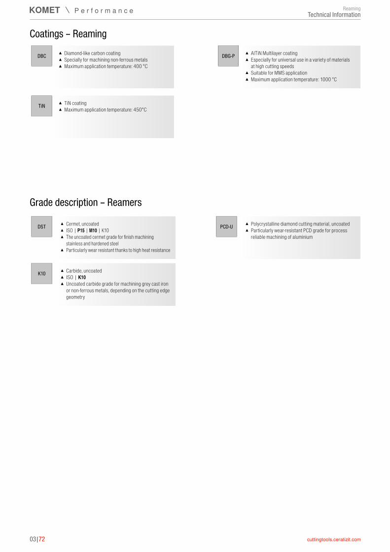
03|72
Coatings – Reaming
DBG-PDBC
TiN
▲ Diamond-like carbon coating ▲ Specially for machining non-ferrous metals ▲ Maximum application temperature: 400 °C
▲ TiN coating ▲ Maximum application temperature: 450°C
▲ AlTiN Multilayer coating ▲ Especially for universal use in a variety of materials
at high cutting speeds ▲ Suitable for MMS application ▲ Maximum application temperature: 1000 °C
▲ Cermet, uncoated ▲ ISO | P15 | M10 | K10 ▲ The uncoated cermet grade for finish machining
stainless and hardened steel ▲ Particularly wear resistant thanks to high heat resistance
Grade description – Reamers
▲ Polycrystalline diamond cutting material, uncoated ▲ Particularly wear-resistant PCD grade for process
reliable machining of aluminium
DST PCD-U
K10 ▲ Carbide, uncoated ▲ ISO | K10 ▲ Uncoated carbide grade for machining grey cast iron
or non-ferrous metals, depending on the cutting edge geometry
ReamingTechnical Information