catalogue capacitive sensors
TRANSCRIPT

3
Edition February 1998With publication of this catalogue all former printed catalogues aboutRECHNER capacitive sensors are invalid.
DimensionsPage 46 - 55
CATALOGUE CAPACITIVE SENSORSTechnologyMountingApplicationTechnical termsPage 4 - 11
Technical dataTypesPage 12 - 45
Testing laboratory accredited according to DIN EN 45001 Reg.-No. DAT-P-048/95-00
Registration-Nr.: 1327-01
Series 40NAMUR2-Wire AnalogPage 12 - 16Mini-SensorsPage 17 - 19
Series 70NPN-3/4-WirePage 20 - 25
Series 80PNP-3/4-Wire3-Wire AnalogPage 26 - 33
Series 2000ProgrammableNPN/PNP/NO/NCPage 34 - 35
Series 902-Wire ACPage 36 - 38
Series 1000programmableAC/DC/NO/NCPage 39 - 40
Temperature-resistant up to+250°CPage 41 - 45

CATALOGUE
CapacitiveSensors

2
For all transactions, the newest version of the "General Conditions of Sale and Delivery for Products andServices of the Electrical Industry ZVEI" shall apply, with the supplementary conditions "extended reservationof proprietary rights", together with the supplements listed on our order confirmations and/or invoices.All specifications are subject to change without notice.Reprint, even in part, only with our consent.© RECHNER 0298 GB - Printed in Germany, all rights reserved.

4
TECHNOLOGY MOUNTING APPLICATION
2-Wire AC
blue
black
Cable Connector Terminals Load
green/yellow
at metal housing only
Amplifier
brown
blue
2-Wire NAMUR
2-Wire Analog2-wire Analog
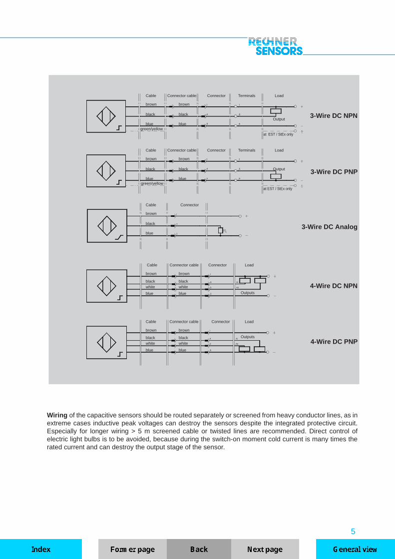
Connection diagrams
The capacitive sensors, our abbreviation KAS , contain a transistor oscillator which is actuated when adefined capacitance is exceeded by the approach of metals, non-metals or liquids. The medium has to beapproached closer the smaller its dielectric permittivity ε
r . This effect can also be achieved by detecting
through non-metal materials, if the dielectric permittivity of the material to be detected is higher (approx.factor 5). Depending on the type the current change of the oscillator will be amplified to a streamlined outputsignal or output as a binary signal by a switching amplifier. Output stages with npn or pnp transistors areavailable for DC operation. A transistor output stage is integrated for AC connection. The output switchingfunction is NO, NC or change-over (antivalent), comparable to mechanical switches. Electronic circuits,PLCs, relays or contactors can be activated directly with capacitive sensors. The current change in theoscillator is caused without contacts by the approach of the actuating material to the active area.The damp-ing of the oscillator is possible between the active surface and specified sensing distance (Sn) + 10 %.The capacitive RECHNER sensors with 20-turn spindle potentiometer allow sensitivity adjustment greateror less than the nominal sensing distance. Under the best operating conditions (e.g. constant ambientconditions) a sensing distance up to the maximum specified value can be adjusted.
The components of the KAS are mounted in plastic or metal casings and encapsulated with epoxy castingresin. The plastics used include PVC (polyvinylchloride), PA (polyamide) 6.6 glass-fibre reinforced andPTFE (polytetrafluor ethylene) or PEEK (polyetheretherketone). Metal housings are made of chrome ornickel-plated brass or of V2A stainless-steel, material No. 1.4301 or 1.4305. By means of this measures alldevices are insensitive to dirt, vibration (vibration stability: 30 g, 100...2000 Hz, 1 hour) and are watertight(depending on the type, up to IP 68). The choice of housings enables a wide range of applications, e.g.with aggressive media, in hot areas or in areas subjected to steam.
Only pre-tested electronic components, proven integrated circuits and hybrid circuits are used and producedwith SMT. The standard constant ambient temperature permitted is -25 up to +70°C , and up to 90°C forbrief periods. High-temperature types for use at -200 up to +250°C are also included in our general productline.
With contactless detection no physical actuating force is required for operation. There is no contact bounce,no sensor wear, no maintenance and the service life is independent of the switching frequency.
5
Outputs
blue blue Outputs
black black
3-Wire DC Analog
3-Wire DC PNP
3-Wire DC NPN
Cable Connector cable Connector Terminals Load
Cable Connector cable Connector Terminals Load
brown brown
black blackOutput
blue blue green/yellow
at EST / StEx only
green/yellow at EST / StEx only
brown
black
blue
Cable Connector
4-Wire DC NPN
Wiring of the capacitive sensors should be routed separately or screened from heavy conductor lines, as inextreme cases inductive peak voltages can destroy the sensors despite the integrated protective circuit.Especially for longer wiring > 5 m screened cable or twisted lines are recommended. Direct control ofelectric light bulbs is to be avoided, because during the switch-on moment cold current is many times therated current and can destroy the output stage of the sensor.
brown brown
black black Output
blue blue
4-Wire DC PNP
brown brown
black blackwhite white
Cable Connector cable Connector Load
Cable Connector cable Connector Load
brown brown
blue blue
white white

6
Series connection Parallel connection
2-Wire AC/DC
3-Wire DC NPN
2- and 3-wire sensors with binary output can be used in series or parallel connection, similar to mechanicalcontacts. The type-typical voltage drop and the residual voltage Ud, which must be multiplied in accordanceto the number of sensors for series connection, must be noted. In the case of parallel connection of sensorswith thyristor output, the first switched output takes over the total load current.
KAS can be used in machines, systems and vehicles for level monitoring of liquids or bulk material, alsothrough non-metal partitions. Further more as limit switches, contact-less position switches for monitoringand positioning, as pulse generator for counting tasks, distance and speed measurements and for manyother applications.
Capacitive analog sensors are equipped with a 20-turn spindle potentiometer. This allows adjustment of anapplication specific operating range between the minimum distance “0 mm” and the type-typical maxi-mum value. Consequently, the full output current travel (4...20 mA) is always present, regardless of therequired measuring distance. The analog sensors of series 80 are designed with a 2-colour LED whichfacilitates adjustment. Outside the operating range IA < 4 mA and IA > 20 mA green light is emitted todisplay operational readiness. Within the operating range of 4...20 mA the LED is red. At the undampedcondition the output current value is > 20 mA and moves with the reduction of the object distance toward 4mA (value at total damping approx. 2.5 mA). In the case of series 40 the current characteristic is reverse-proportional to the object-distance.

7
10
2 4 6
8
6
4
2
8 10 12 14 16
[mA]
I A
20
18
16
14
12
22
2818 20 22 24 26 30[mm]
S
10
2 4 6
8
6
4
2
8 10 12 14 16
[mA]
I
20
18
16
14
12
A
2818 20 22 24 26 30[mm]
S
C D EC = KAS-80-A13-ILD = KAS-80-A14-ILE = KAS-80-30-IL(-M32)
Typ. curve of 3-Wire analog sensors
Parameter:
Tu = 25 °C, UB = 24 V DCActuator:Stainless steel St 37, 1 mm thick,square, side length equal to 3 xdiameter of the active area,earthed.
10
2 4 6
8
6
4
2
8 10 12 14 16
[mA]
I
20
18
16
14
12
A
2818 20 22 24 26 30 32 34 36 S[mm]
Parameter:
Tu = 25 °C, UB = 24 V DCActuator:Stainless steel St 37, 1 mm thick,square, side length equal to 3 xdiameter of the active area,earthed.
1 2 3KAS-80-34-IL-M32-PTFE/Ms1 = Adjustment 20 mm2 = Adjustment 30 mm3 = Adjustment 36 mm
3-Wire analog sensor with different adjustments
Parameter:
Tu = 25 °C, UB = 24 V DCActuator:Stainless steel St 37, 1 mm thick,square, side length equal to 3 xdiameter of the active area, earthed.
Typ. curve of 2-Wire analog sensors
A = KAS-40-A13-ILB = KAS-40-34-IL-M32-StEx
A B
8
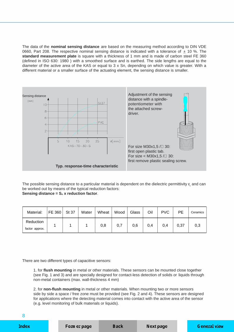
Adjustment of the sensingdistance with a spindle-potentiometer withthe attached screw-driver.
For size M30x1,5 /∅ 30:first open plastic tab.For size < M30x1,5 /∅ 30:first remove plastic sealing screw.
Typ. response-time characteristic
The possible sensing distance to a particular material is dependent on the dielectric permittivity εr and can
be worked out by means of the typical reduction factors:Sensing distance = S n x reduction factor .
Sensing distance
The data of the nominal sensing distance are based on the measuring method according to DIN VDE0660, Part 208. The respective nominal sensing distance is indicated with a tolerance of + 10 %. Thestandard measurement plate is square with a thickness of 1 mm and is made of carbon steel FE 360(defined in ISO 630: 1980 ) with a smoothed surface and is earthed. The side lengths are equal to thediameter of the active area of the KAS or equal to 3 x Sn, depending on which value is greater. With adifferent material or a smaller surface of the actuating element, the sensing distance is smaller.
Material: FE 360 St 37 Water Wheat Wood Glass Oil PVC PE Ceramics
Reduction1 1 1 0,8 0,7 0,6 0,4 0,4 0,37 0,3
factor approx.
There are two different types of capacitive sensors:
1. for flush mounting in metal or other materials. These sensors can be mounted close together(see Fig. 1 and 3) and are specially designed for contact-less detection of solids or liquids throughnon-metal containers (max. wall-thickness 4 mm)
2. for non-flush mounting in metal or other materials. When mounting two or more sensorsside by side a space / free zone must be provided (see Fig. 2 and 4). These sensors are designedfor applications where the detecting material comes into contact with the active area of the sensor(e.g. level monitoring of bulk materials or liquids).

9
Fig.2
Mounting
Fig. 1
Fig. 4
Fig.3
CLEAR AREA, non-damping material
METAL
For opposite activeareas "a" ≥≥≥≥≥ 2,2 x Sn
METAL
For non-flush mountable Sensorsdistance "b" has to be ≥ 1,5 x Sn.
The dimension "e" corresponds to the thread-free area ofstandard sensor types (-A21-...). Otherwise " e" is ≥ ≥ ≥ ≥ ≥ 25 mm.
In order to prevent damage to the threaded sleeves when mounting, the material and version-dependentmaximum torque should be taken into consideration. The values listed in the table are based on the use ofthe nuts supplied with the sensors.
ThreadHousing material
PVC PA 6.6 PTFE Brass Stainless steel
M 5 x 0.5 — — — — 1.5 Nm
M 8 x 1 — — — — 4.5 Nm
M 12 x 1 1.5 Nm 1 Nm 0.2 Nm 16 Nm 25 Nm
M 18 x 1 — 1.7Nm 0.5 Nm 28 Nm 60 Nm
M 22 x 1.5 12 Nm 6 Nm 1.4 Nm 32 Nm 84 Nm
M 30 x 1.5 — 8 Nm 2.5 Nm 82 Nm 200 Nm
M 32 x 1.5 — 13 Nm 3 Nm 150 Nm 230 Nm

10
TECHNICAL TERMS
Due to the permitted thread tolerances specified in German standard DIN 13, the maximum screw-inlength for threaded sensors should be taken into consideration. According to that the lenght of the threadedblock for screwing in proximity sensors should not exceed the following dimensions. In the case of largerthreaded blocks we recommend drilling a blind hole in order to adhere to the maximum screw-in length.
Thread M 5 x 0.5 M 8 x 1 M 12 x 1 M 18 x 1 M 30 x 1.5 M 32 x 1.5
Max. screw-in3 mm 6 mm 8 mm 12 mm 12 mm 12 mm
length
Operating sensing distance / Sa
Within the operating sensing distance the sensor operates reliably in view of all possible tolerances. It liesbetween 0 and 0.81 x Sn.
Minimum sensing distance / Smin
The minimum possible sensing distance, which can be adjusted by potentiometer and which can be usedeffectively in practical applications referred to a medium with ε
r > 80.
Maximum sensing distance / Smax.
The maximum possible sensing distance, which can be adjusted by potentiometer and which can be usedeffectively in practical applications referred to a medium with ε
r > 80. The sensors only should be used under
constant ambient conditions, such as constant temperature, no humidity, no deposits on the active area ofthe sensor.
Nominal sensing distance / Sn
Characteristic value of a proximity sensor, without consideration of the production tolerance and variationsdue to temperature and voltages.
Real sensing distance / Sr
Determined sensing distance at +20 °C and rated voltage. Here the series variance is taken into consideration.Variation max. + 10 %.
Reduction factorsFor other materials than metal (e.g. FE 360 or ST 37, Al, Cu) or water the reduction factors as shown in thetable on page 8 should be taken into consideration.
Series- and parallel connectionIt is possible to connect the proximity sensors in series or parallel. Here it must be taken into account thatthe voltage drops are added for series connection and the residual voltages for parallel connection. Underthese circumstances it is advisable to operate a maximum of three sensors in a corresponding circuit.
Repeat accuracy of the switching pointThe variation of the switching point of two successive measurements at constant ambient conditions.
Frequency of operating cyclesThe maximal damping and un-damping of the proximity sensor within one second. To ascertain the frequencyof operating cycles a pulse / break ratio of 1 : 2 is used as a basis, at Sn ½.

11
Switching hysteresisThe difference between the switch-on and switch-off point of a proximity sensor, when approaching or removingthe standard measuring plate.
Enclosure ratingIP 65: Protection against contact with voltage-carrying parts, protection against ingress of dust and waterjet.IP 67: Protection against contact with voltage-carrying parts, protection against ingress of durst and protectionagainst ingress of water when the equipment is immersed in water, up to 1 m depths and for a period of 30minutes.
Temperature variationThe displacement of the switching point if the ambient temperature changes.
Effective standards for proximity switches and sensors:DIN VDE 0660 Part 208: standard for inductive, capacitive and optical proximity sensors.
KAS - ... - ... - ... - ... - ... - ... - ...
Dimension of thread if presentor K = plastic housing
Special housing if present
Increased temperaturerange if present
Y... = flange connectorCapacitiveproximity sensor
A... = According to Eur opean StandardsC... = Rectangular housingM... = Thread on mini-sensorsNumbers only = Type version
TYPE CODE
40 = NAMUR / 2-Wire analog70 = 3 / 4-Wire DC NPN80 = 3 / 4-Wire DC PNP2000 = 3-Wire DC NPN/PNP/NO/NC90 = 2-Wire AC1000 = 2-Wire AC/DC/NO/NC
S = Function NOÖ = Function NC
A = Antivalent (NO + NC)IL = Analog function
The products of Rechner Industrie-Elektronik GmbH are designed and checked in accordance with thelatest standards and specifications, DIN - VDE - IEC, for electric and electronic instruments. For new andrevised products the newest standards are always used.
Rechner Industrie-Elektronik GmbH is a member of the Association for Testing and Certification of LowVoltage Equipment (ALPHA) e. V., Frankfurt am Main.The independent responsibility of the manufacturer and its assurance of high product quality are supportedby ALPHA with supportive process quidelines for device inspection according to the applicable standards.Our quality assurance operates in accordance with the European standards EN 45001, ALPHA test reportsand LOVAG (Low Voltage Agreement Group) test instructions for proximity sensors according toIEC 947-5-2.
12
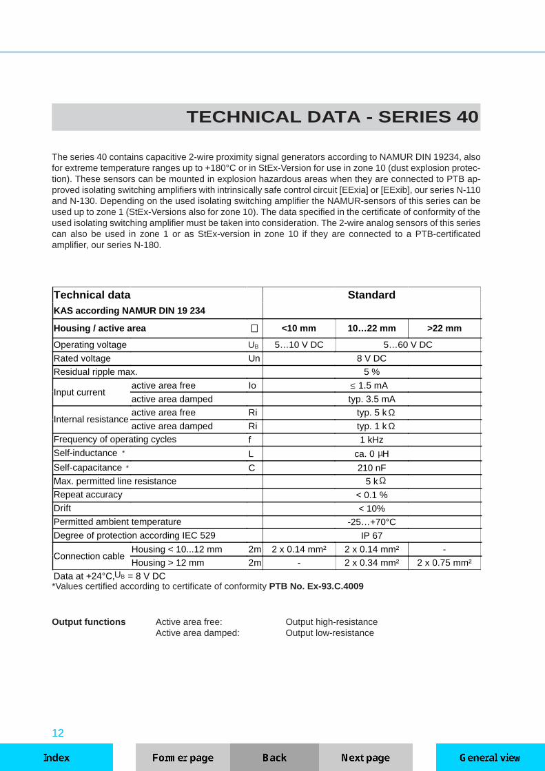
Technical data StandardKAS according NAMUR DIN 19 234
Housing / active area ∅∅ <10 mm 10…22 mm >22 mm
Operating voltage 5…10 V DC 5…60 V DC
Rated voltage Un 8 V DC
Residual ripple max. 5 %
Input currentactive area free Io 1.5 mA
active area damped typ. 3.5 mA
Internal resistanceactive area free Ri typ. 5 k
active area damped Ri typ. 1 kFrequency of operating cycles f 1 kHzSelf-inductance L ca. 0 H
Self-capacitance C 210 nFMax. permitted line resistance 5 kRepeat accuracy < 0.1 %Drift < 10%Permitted ambient temperature -25…+70°C
Degree of protection according IEC 529 IP 67
Connection cableHousing < 10...12 mm 2m 2 x 0.14 mm² 2 x 0.14 mm² -
Housing > 12 mm 2m - 2 x 0.34 mm² 2 x 0.75 mm²
Data at +24°C, = 8 V DC
TECHNICAL DATA - SERIES 40
UB
µ
UB
Ω
ΩΩ
*
*Values certified according to certificate of conformity PTB No. Ex-93.C.4009
Output functions Active area free: Output high-resistanceActive area damped: Output low-resistance
The series 40 contains capacitive 2-wire proximity signal generators according to NAMUR DIN 19234, alsofor extreme temperature ranges up to +180°C or in StEx-Version for use in zone 10 (dust explosion protec-tion). These sensors can be mounted in explosion hazardous areas when they are connected to PTB ap-proved isolating switching amplifiers with intrinsically safe control circuit [EExia] or [EExib], our series N-110and N-130. Depending on the used isolating switching amplifier the NAMUR-sensors of this series can beused up to zone 1 (StEx-Versions also for zone 10). The data specified in the certificate of conformity of theused isolating switching amplifier must be taken into consideration. The 2-wire analog sensors of this seriescan also be used in zone 1 or as StEx-version in zone 10 if they are connected to a PTB-certificatedamplifier, our series N-180.
≤
*

13
ΩRL
UB
µ
Output functions Active area free: Output current < 4 mAActive area covered: Output current 4 mA ... ≥ 20 mA
UB
Technical data AnalogKAS 2-wire analog output
Housing / active area ∅∅ 18 mm >18...30 mm
Operating voltage 5…60 V DC
Rated voltage Un 24 V DC
Residual ripple max. 5 %
Input currentactive area free Io < 2.5 mA
active area damped > 20 mALoad resistance 0...500Linearity error typ. 5 %
Frequency of operating cycles f 300 HzSelf-inductance L < 6 HSelf-capacitance C < 350 nFRepeat accuracy < 0.1 %Drift < 10%Permitted ambient temperature 0…+60°CDegree of protection according to IEC 529 IP 67
Connection cable 2 m 2 x 0.34 mm² 2 x 0.75 mm²
Data at +24°C, = 24 V DC

14
TYPES - SERIES 40
5...60 V DCOscillator output
NAMUR / DIN 19234Series 40
Art. No. TypeSensing dist. [mm] Flush Thread
Material Dim.Sn Min. Max. mounting ∅ [mm]
Cylindrical housing with thread NAMUR versionHousing with standard thread
400100 KAS-40-A11-N * 1.5 - - yes M 8 x 1 PTFE/brass 2·3
400200 KAS-40-A12-N 2 1 5 yes M 12 x 1 PTFE/brass 2·5
400250 KAS-40-A22-N 4 1 6 no M 12 x 1 PTFE/brass 3·2
400300 KAS-40-A13-N 5 1 8 yes M 18 x 1 PTFE/brass 2·7
400350 KAS-40-A23-N 8 2 10 no M 18 x 1 PTFE/brass 3·4
400400 KAS-40-A14-N 10 2 15 yes M 30 x 1.5 PTFE/brass 2·8
400450 KAS-40-A24-N 15 2 20 no M 30 x 1.5 PTFE/brass 3·6
Cylindrical housing with thread NAMUR version
400700 KAS-40-14-N-M12 4 1 6 no M 12 x 1 PVC 3·3
400900 KAS 40-14-N-M12-PTFE 4 1 6 no M 12 x 1 PTFE 3·3
401300 KAS-40-24-N-M22 8 3 10 no M 22 x 1.5 PA 3·5
401500 KAS-40-24-N-M22-PTFE 8 3 10 no M 22 x 1.5 PTFE 3·5
401700 KAS-40-30-N-M32 12 3 15 yes M 32 x 1.5 PA 2·9
401900 KAS-40-30-N-M32-PTFE 12 3 15 yes M 32 x 1.5 PTFE 2·9
402100 KAS-40-35-N-M32 18 3 20 no M 32 x 1.5 PA 3·7
402300 KAS-40-35-N-M32-PTFE 18 3 20 no M 32 x 1.5 PTFE 3·7
402400 KAS-40-34-N-M32-PTFE/V2A 18 3 20 no M 32 x 1.5 PTFE/V2A 3·7
402250 KAS-40-35-N-1"-PTFE 18 3 20 no 1" PTFE 3·8
Cylindrical housing NAMUR version
400500 KAS-40-10-N 2 1 5 yes 11 PTFE/brass 1·4
400600 KAS-40-14-N 4 1 6 no 11 PVC 1·5
400800 KAS-40-14-N-PTFE 4 1 6 no 11 PTFE 1·5
401000 KAS-40-20-N 6 2 8 yes 22 PA 1·7
* Operating voltage 5...10 V DC
15
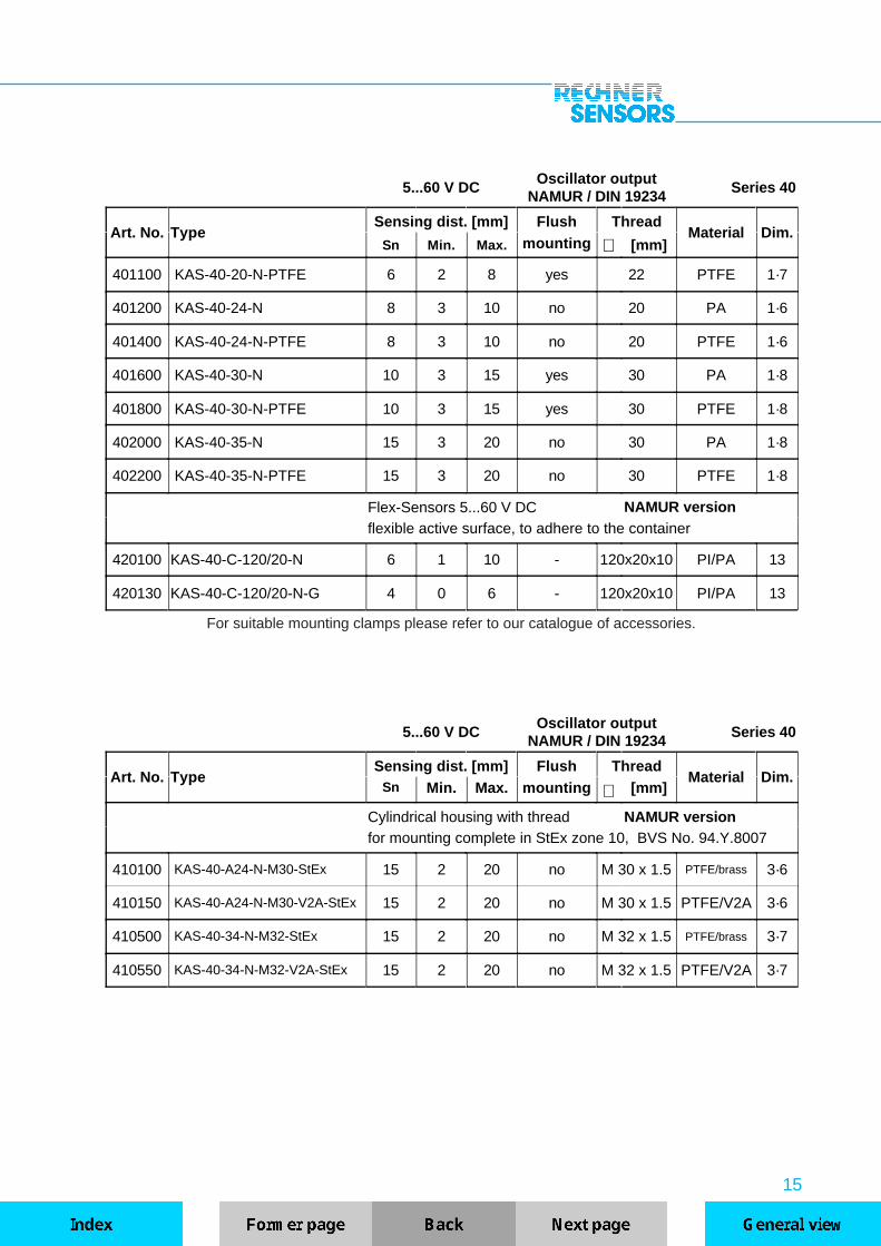
5...60 V DCOscillator output
NAMUR / DIN 19234Series 40
Art. No. TypeSensing dist. [mm] Flush Thread
Material Dim.Sn Min. Max. mounting ∅ [mm]
401100 KAS-40-20-N-PTFE 6 2 8 yes 22 PTFE 1·7
401200 KAS-40-24-N 8 3 10 no 20 PA 1·6
401400 KAS-40-24-N-PTFE 8 3 10 no 20 PTFE 1·6
401600 KAS-40-30-N 10 3 15 yes 30 PA 1·8
401800 KAS-40-30-N-PTFE 10 3 15 yes 30 PTFE 1·8
402000 KAS-40-35-N 15 3 20 no 30 PA 1·8
402200 KAS-40-35-N-PTFE 15 3 20 no 30 PTFE 1·8
Flex-Sensors 5...60 V DC NAMUR versionflexible active surface, to adhere to the container
420100 KAS-40-C-120/20-N 6 1 10 - 120x20x10 PI/PA 13
420130 KAS-40-C-120/20-N-G 4 0 6 - 120x20x10 PI/PA 13
For suitable mounting clamps please refer to our catalogue of accessories.
5...60 V DCOscillator output
NAMUR / DIN 19234Series 40
Art. No. TypeSensing dist. [mm] Flush Thread
Material Dim.Sn Min. Max. mounting ∅ [mm]
Cylindrical housing with thread NAMUR versionfor mounting complete in StEx zone 10, BVS No. 94.Y.8007
410100 KAS-40-A24-N-M30-StEx 15 2 20 no M 30 x 1.5 PTFE/brass 3·6
410150 KAS-40-A24-N-M30-V2A-StEx 15 2 20 no M 30 x 1.5 PTFE/V2A 3·6
410500 KAS-40-34-N-M32-StEx 15 2 20 no M 32 x 1.5 PTFE/brass 3·7
410550 KAS-40-34-N-M32-V2A-StEx 15 2 20 no M 32 x 1.5 PTFE/V2A 3·7
16
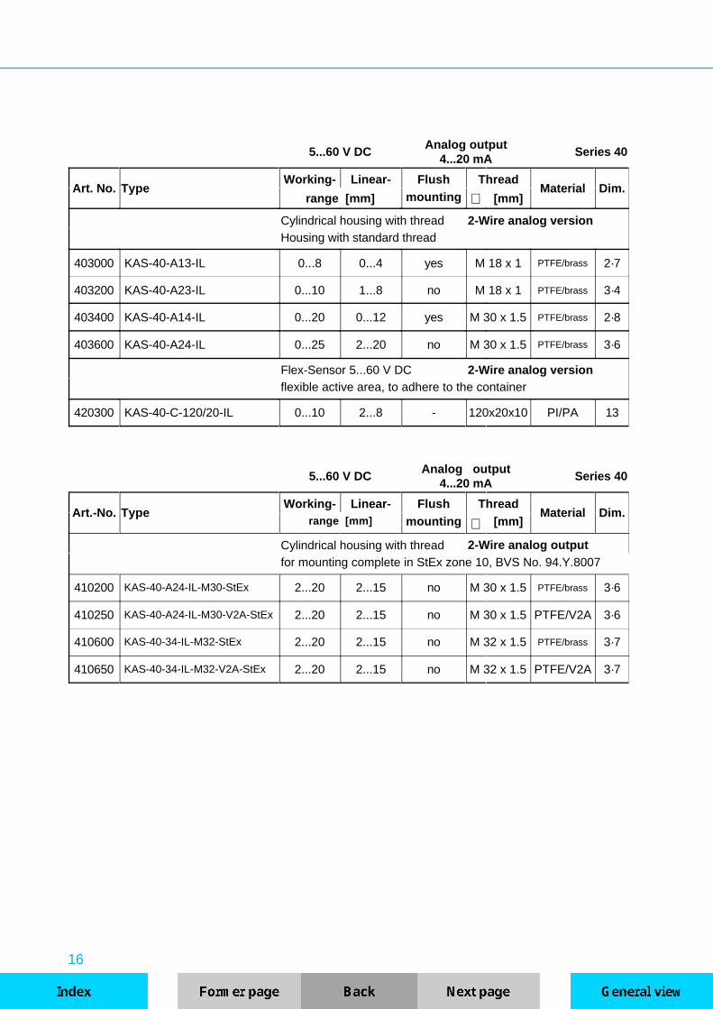
5...60 V DCAnalog output
4...20 mASeries 40
Art. No. TypeWorking- Linear- Flush Thread
Material Dim.range [mm] mounting ∅ [mm]
Cylindrical housing with thread 2-Wire analog versionHousing with standard thread
403000 KAS-40-A13-IL 0...8 0...4 yes M 18 x 1 PTFE/brass 2·7
403200 KAS-40-A23-IL 0...10 1...8 no M 18 x 1 PTFE/brass 3·4
403400 KAS-40-A14-IL 0...20 0...12 yes M 30 x 1.5 PTFE/brass 2·8
403600 KAS-40-A24-IL 0...25 2...20 no M 30 x 1.5 PTFE/brass 3·6
Flex-Sensor 5...60 V DC 2-Wire analog versionflexible active area, to adhere to the container
420300 KAS-40-C-120/20-IL 0...10 2...8 - 120x20x10 PI/PA 13
5...60 V DCAnalog output
4...20 mASeries 40
Art.-No. TypeWorking- Linear- Flush Thread
Material Dim.range [mm] mounting ∅ [mm]
Cylindrical housing with thread 2-Wire analog outputfor mounting complete in StEx zone 10, BVS No. 94.Y.8007
410200 KAS-40-A24-IL-M30-StEx 2...20 2...15 no M 30 x 1.5 PTFE/brass 3·6
410250 KAS-40-A24-IL-M30-V2A-StEx 2...20 2...15 no M 30 x 1.5 PTFE/V2A 3·6
410600 KAS-40-34-IL-M32-StEx 2...20 2...15 no M 32 x 1.5 PTFE/brass 3·7
410650 KAS-40-34-IL-M32-V2A-StEx 2...20 2...15 no M 32 x 1.5 PTFE/V2A 3·7
17
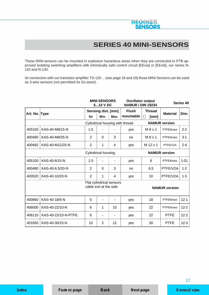
SERIES 40 MINI-SENSORS
These MINI-sensors can be mounted in explosion hazardous areas when they are connected to PTB ap-proved isolating switching amplifiers with intrinsically safe control circuit [EExia] or [EExib], our series N-110 and N-130.
IIn connection with our transistor amplifier TS-120… (see page 18 and 19) these MINI-Sensors can be usedas 3-wire sensors (not permitted for Ex-area!).
MINI-SENSORS5...10 V DC
Oscillator outputNAMUR / DIN 19234
Series 40
Art. No. TypeSensing dist. [mm] Flush Thread
Material Dim.Sn Min. Max. mountable ∅ [mm]
Cylindrical housing with thread NAMUR version
405150 KAS-40-M8/15-N 1.5 - - yes M 8 x 1 PTFE/brass 2·2
400490 KAS-40-M8/25-N 2 0 3 no M 8 x 1 PTFE/brass 3·1
400492 KAS-40-M12/25-N 2 1 4 yes M 12 x 1 PTFE/V2A 2·4
Cylindrical housing NAMUR version
405100 KAS-40-6/15-N 1.5 - - yes 6 PTFE/brass 1·01
400480 KAS-40-6.5/20-N 2 0 3 no 6.5 PTFE/V2A 1·2
400520 KAS-40-10/20-N 2 1 4 yes 10 PTFE/V2A 1·3
Flat cylindrical sensorscable exit at the side NAMUR version
400960 KAS-40-18/5-N 5 - - yes 18 PTFE/brass 12·1
406000 KAS-40-22/10-N 6 1 10 yes 22 PTFE/brass 12·2
406110 KAS-40-22/10-N-PTFE 6 - - yes 22 PTFE 12·2
401650 KAS-40-30/15-N 10 2 12 yes 30 PTFE 12·3

18
TECHNICAL DATA TS-120
Dimensions
Outer diameter of thesensor cable max. 3 mm
UB
I0
IeIm
Un
Ud
Ir
This transistor switching amplifier has been designed especially for use with our capacitive mini-sensorsaccording to NAMUR (e.g. KAS-40-6/15-N, KAS-40-A11-N, KAS-40-18/5-N ) All sensors according to NAMURDIN 19234 are connectable, our series IAS-30... and KAS-40... The sensing distance is adjustable bymeans of a potentiometer, this also applies to capacitive sensors that have no adjustment possibilities oftheir own. The antivalent outputs (NO and NC-function) are overload protected and available as pnp or npn-outputs. The amplifier housing out of PA 6.6 may be mounted with additional units, it is equipped with a two-colour LED display that monitors stand-by (green) operating condition (red). Sensor and amplifier may beconnected by a plug contact (female connector is enclosed).Switching functions:When connecting KAS blue wire = NO, brown wire = NCWhen connecting IAS blue wire = NC, brown wire = NO
Technical Data TS-120-...-AOperating voltage 10…35 V DCRated voltage 24 V DCMax. permitted residual ripple < 10 %
No-load current typ. 15 mAOutput current max. 250 mALoad current min. 0 mA
Residual current 0 mAVoltage drop max. < 3.5 VSwitching frequency max. 3.5 kHz (depending on connected sensor)Temperature variation < 10 %Permitted ambient temperature -25…+70°C
LED indication red/green built-inOverload protection built-inShort-circuit protection built-in
Polarity protection built-inEnclosure rating IEC 529 IP 65
Connection cable 2m; PUR 4 x 0.14 mm²
Data at +24°C, = 24V DC not permitted for Ex-AreaUB

19
Connection diagramwhiteblue
NAMUR-Connection
blackbrown
Connection diagramsoldering sideArt.-No. Type Operating v. Input Output
V DC NAMUR Transistor
500150 TS-120-NPN-A 10…35 1 npn-antivalent
500350 TS-120-PNP-A 10…35 1 pnp-antivalent
20
TECHNICAL DATA - SERIES 70
UB
Switching functions S = NO Active surface free: 0-SignalActive surface covered: 1-Signal / negative potential
Ö = NC Active surface free: 1-Signal / negative potentialActive surface covered: 0-Signal
A = Antivalent Active surface free: 0-Signal (black wire A1)1-Signal (white wire A2)
Active surface covered: 1-Signal (black wire A1)0-Signal (white wire A2)
UB
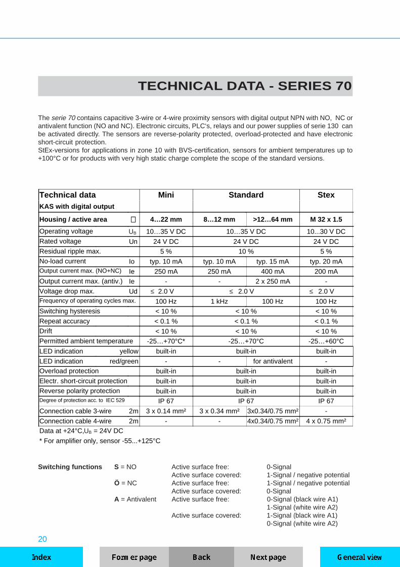
The serie 70 contains capacitive 3-wire or 4-wire proximity sensors with digital output NPN with NO, NC orantivalent function (NO and NC). Electronic circuits, PLC‘s, relays and our power supplies of serie 130 canbe activated directly. The sensors are reverse-polarity protected, overload-protected and have electronicshort-circuit protection.StEx-versions for applications in zone 10 with BVS-certification, sensors for ambient temperatures up to+100°C or for products with very high static charge complete the scope of the standard versions.
Technical data Mini Standard StexKAS with digital output
Housing / active area ∅∅ 4…22 mm 8…12 mm >12…64 mm M 32 x 1.5
Operating voltage 10…35 V DC 10…35 V DC 10...30 V DCRated voltage Un 24 V DC 24 V DC 24 V DCResidual ripple max. 5 % 10 % 5 %No-load current Io typ. 10 mA typ. 10 mA typ. 15 mA typ. 20 mAOutput current max. (NO+NC) Ie 250 mA 250 mA 400 mA 200 mAOutput current max. (antiv.) Ie - - 2 x 250 mA -
Voltage drop max. Ud 2.0 V 2.0 V 2.0 VFrequency of operating cycles max. 100 Hz 1 kHz 100 Hz 100 HzSwitching hysteresis < 10 % < 10 % < 10 %
Repeat accuracy < 0.1 % < 0.1 % < 0.1 %Drift < 10 % < 10 % < 10 %Permitted ambient temperature -25…+70°C* -25…+70°C -25…+60°C
LED indication yellow built-in built-in built-in
LED indication red/green - - for antivalent -Overload protection built-in built-in built-in
Electr. short-circuit protection built-in built-in built-inReverse polarity protection built-in built-in built-inDegree of protection acc. to IEC 529 IP 67 IP 67 IP 67
Connection cable 3-wire 2m 3 x 0.14 mm² 3 x 0.34 mm² 3x0.34/0.75 mm² -
Connection cable 4-wire 2m - - 4x0.34/0.75 mm² 4 x 0.75 mm²Data at +24°C, = 24V DC
* For amplifier only, sensor -55...+125°C
≤ ≤ ≤
21
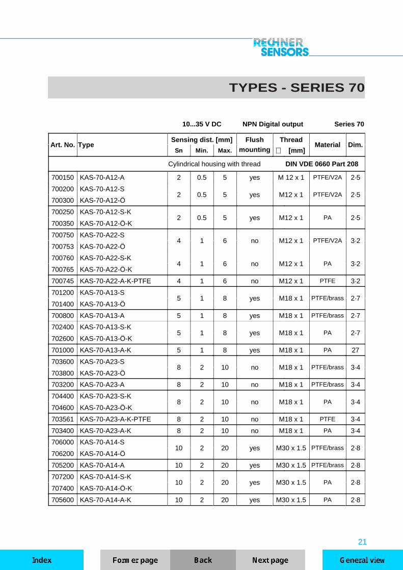
TYPES - SERIES 70
10...35 V DC NPN Digital output Series 70
Art. No. TypeSensing dist. [mm] Flush Thread
Material Dim.Sn Min. Max. mounting ∅ [mm]
Cylindrical housing with thread DIN VDE 0660 Part 208
700150 KAS-70-A12-A 2 0.5 5 yes M 12 x 1 PTFE/V2A 2·5
700200 KAS-70-A12-S2 0.5 5 yes M12 x 1 PTFE/V2A 2·5
700300 KAS-70-A12-Ö
700250 KAS-70-A12-S-K2 0.5 5 yes M12 x 1 PA 2·5
700350 KAS-70-A12-Ö-K
700750 KAS-70-A22-S4 1 6 no M12 x 1 PTFE/V2A 3·2
700753 KAS-70-A22-Ö
700760 KAS-70-A22-S-K4 1 6 no M12 x 1 PA 3·2
700765 KAS-70-A22-Ö-K
700745 KAS-70-A22-A-K-PTFE 4 1 6 no M12 x 1 PTFE 3·2
701200 KAS-70-A13-S5 1 8 yes M18 x 1 PTFE/brass 2·7
701400 KAS-70-A13-Ö
700800 KAS-70-A13-A 5 1 8 yes M18 x 1 PTFE/brass 2·7
702400 KAS-70-A13-S-K5 1 8 yes M18 x 1 PA 2·7
702600 KAS-70-A13-Ö-K
701000 KAS-70-A13-A-K 5 1 8 yes M18 x 1 PA 27
703600 KAS-70-A23-S8 2 10 no M18 x 1 PTFE/brass 3·4
703800 KAS-70-A23-Ö
703200 KAS-70-A23-A 8 2 10 no M18 x 1 PTFE/brass 3·4
704400 KAS-70-A23-S-K8 2 10 no M18 x 1 PA 3·4
704600 KAS-70-A23-Ö-K
703561 KAS-70-A23-A-K-PTFE 8 2 10 no M18 x 1 PTFE 3·4
703400 KAS-70-A23-A-K 8 2 10 no M18 x 1 PA 3·4
706000 KAS-70-A14-S10 2 20 yes M30 x 1.5 PTFE/brass 2·8
706200 KAS-70-A14-Ö
705200 KAS-70-A14-A 10 2 20 yes M30 x 1.5 PTFE/brass 2·8
707200 KAS-70-A14-S-K10 2 20 yes M30 x 1.5 PA 2·8
707400 KAS-70-A14-Ö-K
705600 KAS-70-A14-A-K 10 2 20 yes M30 x 1.5 PA 2·8

22
10...35 V DC NPN Digital output Series 70
Art. No. TypeSensing dist. [mm] Flush Thread
Material Dim.Sn Min. Max. mounting ∅ [mm]
708800 KAS-70-A24-S15 3 25 no M30 x 1.5 PTFE/brass 3·6
709000 KAS-70-A24-Ö
708000 KAS-70-A24-A 15 3 25 no M30 x 1.5 PTFE/brass 3·6
709600 KAS-70-A24-S-K15 3 25 no M30 x 1.5 PA 3·6
709800 KAS-70-A24-Ö-K
708401 KAS-70-A24-A-K-PTFE 15 3 25 no M30 x 1.5 PTFE 3·6
708400 KAS-70-A24-A-K 15 3 25 no M30 x 1.5 PA 3·6
Cylindrical housing with thread standard version
711000 KAS-70-14-S-M12 4 2 6 no M12 x 1 PVC 3·3
713600 KAS-70-23-S-M2210 2 15 no M22 x 1.5 PA 3·5
713800 KAS-70-23-Ö-M22
713400 KAS-70-23-A-M22 10 2 15 no M22 x 1.5 PA 3·5
716200 KAS-70-30-S-M3215 2 25 yes M32 x 1.5 PA/brass 2·9
716400 KAS-70-30-Ö-M32
715800 KAS-70-30-A-M32 15 2 25 yes M32 x 1.5 PA/brass 2·9
720600 KAS-70-35-S-M3220 3 30 no M32 x 1.5 PA 3·7
720800 KAS-70-35-Ö-M32
720200 KAS-70-35-A-M32 20 3 30 no M32 x 1.5 PA 3·7
720300 KAS-70-35-A-M32-PTFE 20 3 30 no M32 x 1.5 PTFE 3·7
717400 KAS-70-34-S-M32-PVC/Ms20 3 30 no M 32 x 1.5 PVC/brass 3·7
717600 KAS-70-34-Ö-M32-PVC/Ms
718200 KAS-70-34-S-M32-PTFE/Ms20 3 30 no M32 x 1.5 PTFE/brass 3·7
718400 KAS-70-34-Ö-M32-PTFE/Ms
718600 KAS-70-34-S-M32-PTFE/V2A20 3 30 no M32 x 1.5 PTFE/V2A 3·7
718800 KAS-70-34-Ö-M32-PTFE/V2A
719150 KAS-70-35-A-1"-PTFE 20 3 30 no 1" PTFE 3·8
Cylindrical housing standard version
710600 KAS-70-10-S 2 0.5 5 yes 11 PTFE/brass 1·4
710800 KAS-70-14-S 4 2 6 no 11 PVC 1·5
711800 KAS-70-20-S6 2 10 yes 22 PA/brass 1·7
712000 KAS-70-20-Ö

23
For suitable mounting clamps please refer to our catalogue of accessories.
10...35 V DC NPN Digital output Series 70
Art. No. TypeSensing dist. [mm] Flush Thread
Material Dim.Sn Min. Max. mounting ∅ [mm]
711600 KAS-70-20-A 6 2 10 yes 22 PA/brass 1·7
713000 KAS-70-23-S10 3 15 no 20 PA 1·6
713200 KAS-70-23-Ö
712800 KAS-70-23-A 10 3 15 no 20 PA 1·6
714600 KAS-70-30-S15 2 25 yes 30 PA/brass 1·8
714800 KAS-70-30-Ö
714200 KAS-70-30-A 15 2 25 yes 30 PA/brass 1·8
719400 KAS-70-35-S20 3 30 no 30 PA 1·8
719600 KAS-70-35-Ö
719010 KAS-70-35-A-PTFE 20 3 30 no 30 PTFE 1·8
719000 KAS-70-35-A 20 3 30 no 30 PA 1·8
724600 KAS-70-37-S18 3 30 yes 34 PA 1·9
724800 KAS-70-37-Ö
724500 KAS-70-37-A 18 3 30 yes 34 PA 1·9
725400 KAS-70-38-S22 3 35 no 34 PA 1·9
725600 KAS-70-38-Ö
725300 KAS-70-38-A 22 3 35 no 34 PA 1·9
726200 KAS-70-40-S20 3 30 yes 40 PA 1·10
726400 KAS-70-40-Ö
726600 KAS-70-41-S25 4 40 no 40 PA 1·10
726800 KAS-70-41-Ö
727000 KAS-70-50-S25 4 40 yes 50 PA 1·11
727200 KAS-70-50-Ö
727400 KAS-70-53-S30 4 50 no 50 PA 1·11
727600 KAS-70-53-Ö
727800 KAS-70-61-S35 6 60 no 64 PA 1·12
728000 KAS-70-61-Ö
Rectangular housing standard version
728200 KAS-70-C5-S 2 0.5 5 yes 40x26x12 PA 11

24
10...35 V DC NPN Digital output Series 70
Art. No. TypeSensing dist. [mm] Flush Thread
Material Dim.Sn Min. Max. mounting ∅ [mm]
Cylindrical housing with thread DIN VDE 0660 Part 208
with plastic flange connector M12 x 1 and LED display
700700 KAS-70-A12-S-Y32 0.5 5 yes M12 x 1 PTFE/V2A 5·1
700720 KAS-70-A12-Ö-Y3
700770 KAS-70-A22-S-Y34 1 6 no M 12 x 1 PTFE/V2A 5·2
700772 KAS-70-A22-Ö-Y3
702000 KAS-70-A13-S-Y35 1 8 yes M18 x 1 PTFE/brass 6·1
702200 KAS-70-A13-Ö-Y3
704000 KAS-70-A23-S-Y38 2 10 no M18 x 1 PTFE/brass 6·2
704200 KAS-70-A23-Ö-Y3
704800 KAS-70-A23-S-K-Y38 2 10 no M18 x 1 PA 6·3
705000 KAS-70-A23-Ö-K-Y3
Cylindrical housing with thread DIN VDE 0660 Part 208
with metal flange connector M12x1 without LED
700725 KAS-70-A12-S-Y52 0.5 5 yes M12 x 1 PTFE/brass 5·1
700727 KAS-70-A12-Ö-Y5
702050 KAS-70-A13-S-Y55 1 8 yes M18 x 1 PTFE/brass 6·1
702055 KAS-70-A13-Ö-Y5
704100 KAS-70-A23-S-Y58 2 10 no M18 x 1 PTFE/brass 6·2
704300 KAS-70-A23-Ö-Y5
Cylindrical housing with thread DIN VDE 0660 Part 208
with metal flange connector M12 x 1 and LED display
706800 KAS-70-A14-S-Y510 2 20 yes M30 x 1.5 PTFE/brass 6·4
707000 KAS-70-A14-Ö-Y5
705400 KAS-70-A14-A-Y5 10 2 20 yes M30 x 1.5 PTFE/brass 6·4
709200 KAS-70-A24-S-Y515 3 25 no M30 x 1.5 PTFE/brass 6·5
709400 KAS-70-A24-Ö-Y5
708200 KAS-70-A24-A-Y5 15 3 25 no M30 x 1.5 PTFE/brass 6·5
Cylindrical housing with thread Standard version
with metal flange connector M12 x 1 and LED display
717000 KAS-70-30-S-M32-Y515 2 25 yes M32 x 1.5 PA/brass 6·6
717200 KAS-70-30-Ö-M32-Y5
716000 KAS-70-30-A-M32-Y5 15 2 25 yes M32 x 1.5 PA/brass 6·6
721000 KAS-70-35-S-M32-Y520 3 30 no M32 x 1.5 PA 7·1
721200 KAS-70-35-Ö-M32-Y5
720400 KAS-70-35-A-M32-Y5 20 3 30 no M32 x 1.5 PA 7·1

25
10...35 V DC NPN Digital output Series 70
Art. No. TypeSensing dist. [mm] Flush Thread
Material Dim.Sn Min. Max. mounting ∅ [mm]
Cylindrical housing with thread special version
resistant to pressure up to 20 bar
720745 KAS-70-35-A-M32-20 bar 20 3 30 no M32 x 1.5 PVC/brass 9
Cylindrical housing with thread special version
for level control of materials with static charge up to 25 KV(with protective conductor)
717310 KAS-70-34-A-M32-PTFE/Ms-EST 18 3 25 no M32 x 1.5 PTFE/brass 3·7
Cylindrical housing with thread special version
for level control of adhesive or crystalline products with highrelative dielectric permittivity
712912 KAS-70-23-A-M22-PTFE-G 5 0 5 no M 22 x 1.5 PTFE 3·5
717320 KAS-70-34-A-M32-PTFE/V2A-G 8 0 8 no M 32 x 1.5 PTFE/V2A 3·7
Cylindrical housing with thread StEx version
Dust explosion-proof for zone 10 BVS-No.StEx 7/81 B
723780 KAS-70-35-A-M32-StEx-N 20 3 30 no M32 x 1.5 PTFE/brass 9
723790 KAS-70-35-A-M32-StEx-N/V2A 20 3 30 no M32 x 1.5 PTFE/V2A 9
Note when ordering StEx units: Indicate wall-thickness of the container [mm] as outer nut must be either glued or soldered in position(BVS-instruction).
10...35 V DC NPN Digital output Series 70
Art. No. TypeSensing dist. [mm] Flush Sensor housing [mm]
Dim.Sn Min. Max. mounting ∅ l Material
Capacitive MINI-sensors, amplifierseparate, with 400 mm sensor cable
Mini version
sensor for use at -55...+125°C, amplifier for use at -25...+70°C
730200 KAS-70-C-4/15-S0.8 0 1 yes 4 15 PTFE/brass
1·0
730400 KAS-70-C-4/15-Ö 18
730600 KAS-70-C-M5/20-S0.8 0 1 yes M5x0.5 20 PTFE/brass
2·1
730800 KAS-70-C-M5/20-Ö 18
Further capacitive MINI-sensors on page 17.

26
UB
TECHNICAL DATA - SERIES 80
Switching functions:S = NO Active area free: 0-Signal
Active area covered: 1-Signal / positive potentialÖ = NC Active area free: 1-Signal / positive potential
Active area covered: 0-SignalA = Antivalent Active area free: 0-Signal (black wire A1)
1-Signal (white wire A2) Active area covered: 1-Signal (black wire A1)
0-Signal (white wire A2)
UB
The series 80 contains capacitive 3-wire or 4-wire proximity sensors with digital output PNP with NO, NC orantivalent function (NO and NC). Electronic circuits, PLC‘s, relays and our power supplies of series 130 canbe activated directly. The sensors are reverse-polarity protected, overload-protected and have electronicshort-circuit protection.StEx-versions for applications in zone 10 with BVS-certification, sensors for ambient temperatures up to+100°C or for products with very high static charge complete the scope of the standard versions.
Technical data Mini Standard StexKAS with digital output
Housing / active area ∅∅ 4…22 mm 8…12 mm >12…64 mm M 32 x 1.5
Operating voltage 10…35 V DC 10…35 V DC 10...30 V DCRated voltage Un 24 V DC 24 V DC 24 V DCResidual ripple max. 5 % 10 % 5 %No-load current Io typ. 10 mA typ. 10 mA typ. 15 mA typ. 20 mAOutput current max. (NO+NC) Ie 250 mA 250 mA 400 mA 200 mAOutput current max. (antiv.) Ie - - 2 x 250 mA -
Voltage drop max. Ud 2.0 V 2.0 V 2.0 VFrequency of operating cycles max. 100 Hz 1 kHz 100 Hz 100 HzSwitching hysteresis < 10 % < 10 % < 10 %
Repeat accuracy < 0.1 % < 0.1 % < 0.1 %Drift < 10 % < 10 % < 10 %Permitted ambient temperature -25…+70°C* -25…+70°C -25…+60°C
LED indication yellow built-in built-in built-in
LED indication red/green - - for antivalent -Overload protection built-in built-in built-in
Electr. short-circuit protection built-in built-in built-inReverse polarity protection built-in built-in built-inDegree of protection acc. to IEC 529 IP 67 IP 67 IP 67
Connection cable 3-wire 2m 3 x 0.14 mm² 3 x 0.34 mm² 3x0.34/0.75 mm² -
Connection cable 4-wire 2m - - 4x0.34/0.75 mm² 4 x 0.75 mm²Data at +24°C, = 24V DC
* For amplifier only, sensor -55...+125°C
≤ ≤ ≤
27
UB
UB
RL
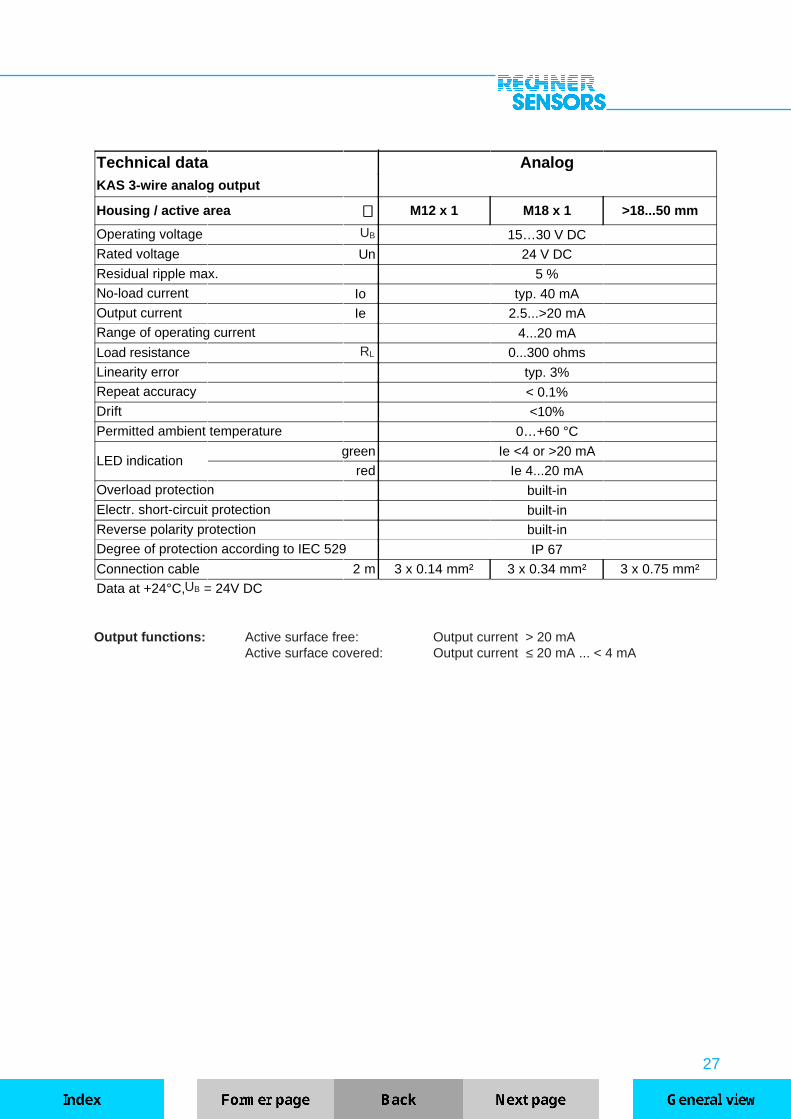
Output functions: Active surface free: Output current > 20 mAActive surface covered: Output current ≤ 20 mA ... < 4 mA
Technical data AnalogKAS 3-wire analog output
Housing / active area ∅∅ M12 x 1 M18 x 1 >18...50 mm
Operating voltage 15…30 V DCRated voltage Un 24 V DC
Residual ripple max. 5 %No-load current Io typ. 40 mAOutput current Ie 2.5...>20 mARange of operating current 4...20 mA
Load resistance 0...300 ohms
Linearity error typ. 3%Repeat accuracy < 0.1%Drift <10%
Permitted ambient temperature 0…+60 °C
LED indicationgreen Ie <4 or >20 mA
red Ie 4...20 mAOverload protection built-inElectr. short-circuit protection built-inReverse polarity protection built-inDegree of protection according to IEC 529 IP 67
Connection cable 2 m 3 x 0.14 mm² 3 x 0.34 mm² 3 x 0.75 mm²
Data at +24°C, = 24V DC

28
TYPES - SERIES 80
10...35 V DC PNP Digital output Series 80
Art. No. TypeSensing dist. [mm] Flush Thread
Material Dim.Sn Min. Max. mounting ∅ [mm]
Cylindrical housing with thread DIN VDE 0660 Part 208
800150 KAS-80-A12-A 2 0.5 5 yes M12 x 1 PTFE/V2A 2·5
800200 KAS-80-A12-S2 0.5 5 yes M12 x 1 PTFE/V2A 2·5
800300 KAS-80-A12-Ö
800250 KAS-80-A12-S-K2 0.5 5 yes M12 x 1 PA 2·5
800350 KAS-80-A12-Ö-K
800750 KAS-80-A22-S4 1 6 no M12 x 1 PTFE/V2A 3·2
800753 KAS-80-A22-Ö
800760 KAS-80-A22-S-K4 1 6 no M12 x 1 PA 3·2
800765 KAS-80-A22-Ö-K
800745 KAS-80-A22-A-K-PTFE 4 1 6 no M12 x 1 PTFE 3·2
801200 KAS-80-A13-S5 1 8 yes M18 x 1 PTFE/brass 2·7
801400 KAS-80-A13-Ö
800800 KAS-80-A13-A 5 1 8 yes M18 x 1 PTFE/brass 2·7
802400 KAS-80-A13-S-K5 1 8 yes M18 x 1 PA 2·7
802600 KAS-80-A13-Ö-K
801000 KAS-80-A13-A-K 5 1 8 yes M18 x 1 PA 2·7
803600 KAS-80-A23-S8 2 10 no M18 x 1 PTFE/brass 3·4
803800 KAS-80-A23-Ö
803200 KAS-80-A23-A 8 2 10 no M18 x 1 PTFE/brass 3·4
804400 KAS-80-A23-S-K8 2 10 no M18 x 1 PA 3·4
804600 KAS-80-A23-Ö-K
803561 KAS-80-A23-A-K-PTFE 8 2 10 no M18 x 1 PTFE 3·4
803400 KAS-80-A23-A-K 8 2 10 no M18 x 1 PA 3·4
806000 KAS-80-A14-S10 2 20 yes M30 x 1.5 PTFE/brass 2·8
806200 KAS-80-A14-Ö
805200 KAS-80-A14-A 10 2 20 yes M30 x 1.5 PTFE/brass 2·8
807200 KAS-80-A14-S-K10 2 20 yes M30 x 1.5 PA 2·8
807400 KAS-80-A14-Ö-K
805600 KAS-80-A14-A-K 10 2 20 yes M30 x 1.5 PA 2·8

29
10...35 V DC PNP Digital output Series 80
Art. No. TypeSensing dist. [mm] Flush Thread
Material DimSn Min. Max. mounting ∅ [mm]
808800 KAS-80-A24-S15 3 25 no M30 x 1.5 PTFE/brass 3·6
809000 KAS-80-A24-Ö
808000 KAS-80-A24-A 15 3 25 no M30 x 1.5 PTFE/brass 3·6
809600 KAS-80-A24-S-K15 3 25 no M30 x 1.5 PA 3·6
809800 KAS-80-A24-Ö-K
808401 KAS-80-A24-A-K-PTFE 15 3 25 no M30 x 1.5 PTFE 3·6
808400 KAS-80-A24-A-K 15 3 25 no M30 x 1.5 PA 3·6
Cylindrical housing with thread standard version
811000 KAS-80-14-S-M12 4 2 6 no M12 x 1 PVC 3·3
813600 KAS-80-23-S-M2210 2 15 no M22 x 1.5 PA 3·5
813800 KAS-80-23-Ö-M22
813400 KAS-80-23-A-M22 10 2 15 no M22 x 1.5 PA 3·5
816200 KAS-80-30-S-M3215 2 25 yes M32 x 1.5 PA/brass 2·9
816400 KAS-80-30-Ö-M32
815800 KAS-80-30-A-M32 15 2 25 yes M32 x 1.5 PA/brass 2·9
820600 KAS-80-35-S-M3220 3 30 no M32 x 1.5 PA 3·7
820800 KAS-80-35-Ö-M32
820200 KAS-80-35-A-M32 20 3 30 no M32 x 1.5 PA 3·7
820300 KAS-80-35-A-M32-PTFE 20 3 30 no M32 x 1.5 PTFE 3·7
817400 KAS-80-34-S-M32-PVC/Ms20 3 30 no M32 x 1.5 PVC/brass 3·7
817600 KAS-80-34-Ö-M32-PVC/Ms
818200 KAS-80-34-S-M32-PTFE/Ms20 3 30 no M32 x 1.5 PTFE/brass 3·7
818400 KAS-80-34-Ö-M32-PTFE/Ms
818600 KAS-80-34-S-M32-PTFE/V2A20 3 30 no M32 x 1.5 PTFE/V2A 3·7
818800 KAS-80-34-Ö-M32-PTFE/V2A
819150 KAS-80-35-A-1"-PTFE 20 3 30 no 1" PTFE 3·8
Cylindrical housing standard version
710600 KAS-80-10-S 2 0.5 5 yes 11 PTFE/brass 1·4
710800 KAS-80-14-S 4 2 6 no 11 PVC 1·5
711800 KAS-80-20-S6 2 10 yes 22 PA/brass 1·7
712000 KAS-80-20-Ö
30
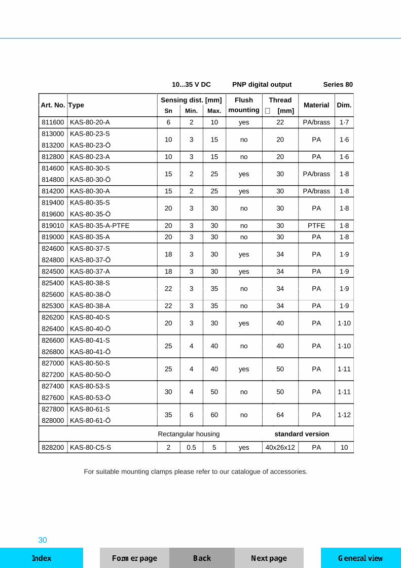
10...35 V DC PNP digital output Series 80
Art. No. TypeSensing dist. [mm] Flush Thread
Material Dim.Sn Min. Max. mounting ∅ [mm]
811600 KAS-80-20-A 6 2 10 yes 22 PA/brass 1·7
813000 KAS-80-23-S10 3 15 no 20 PA 1·6
813200 KAS-80-23-Ö
812800 KAS-80-23-A 10 3 15 no 20 PA 1·6
814600 KAS-80-30-S15 2 25 yes 30 PA/brass 1·8
814800 KAS-80-30-Ö
814200 KAS-80-30-A 15 2 25 yes 30 PA/brass 1·8
819400 KAS-80-35-S20 3 30 no 30 PA 1·8
819600 KAS-80-35-Ö
819010 KAS-80-35-A-PTFE 20 3 30 no 30 PTFE 1·8
819000 KAS-80-35-A 20 3 30 no 30 PA 1·8
824600 KAS-80-37-S18 3 30 yes 34 PA 1·9
824800 KAS-80-37-Ö
824500 KAS-80-37-A 18 3 30 yes 34 PA 1·9
825400 KAS-80-38-S22 3 35 no 34 PA 1·9
825600 KAS-80-38-Ö
825300 KAS-80-38-A 22 3 35 no 34 PA 1·9
826200 KAS-80-40-S20 3 30 yes 40 PA 1·10
826400 KAS-80-40-Ö
826600 KAS-80-41-S25 4 40 no 40 PA 1·10
826800 KAS-80-41-Ö
827000 KAS-80-50-S25 4 40 yes 50 PA 1·11
827200 KAS-80-50-Ö
827400 KAS-80-53-S30 4 50 no 50 PA 1·11
827600 KAS-80-53-Ö
827800 KAS-80-61-S35 6 60 no 64 PA 1·12
828000 KAS-80-61-Ö
Rectangular housing standard version
828200 KAS-80-C5-S 2 0.5 5 yes 40x26x12 PA 10
For suitable mounting clamps please refer to our catalogue of accessories.
31
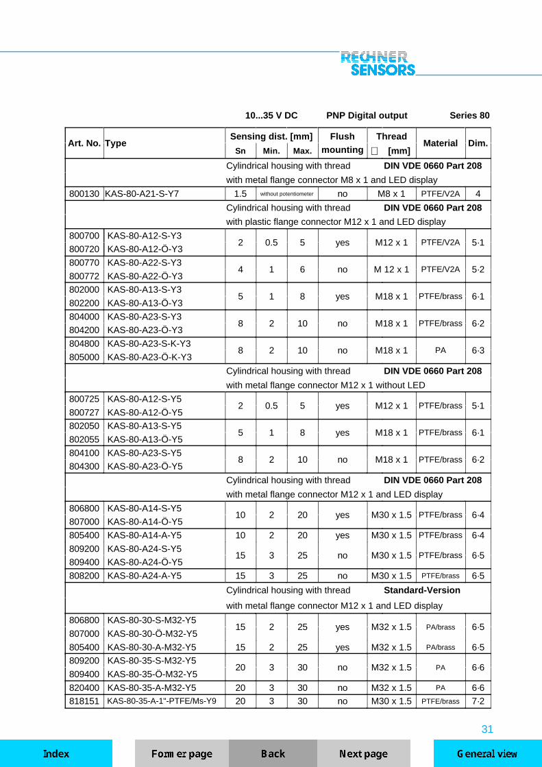
10...35 V DC PNP Digital output Series 80
Art. No. TypeSensing dist. [mm] Flush Thread
Material Dim.Sn Min. Max. mounting ∅ [mm]
Cylindrical housing with thread DIN VDE 0660 Part 208
with metal flange connector M8 x 1 and LED display
800130 KAS-80-A21-S-Y7 1.5 without potentiometer no M8 x 1 PTFE/V2A 4
Cylindrical housing with thread DIN VDE 0660 Part 208
with plastic flange connector M12 x 1 and LED display
800700 KAS-80-A12-S-Y32 0.5 5 yes M12 x 1 PTFE/V2A 5·1
800720 KAS-80-A12-Ö-Y3
800770 KAS-80-A22-S-Y34 1 6 no M 12 x 1 PTFE/V2A 5·2
800772 KAS-80-A22-Ö-Y3
802000 KAS-80-A13-S-Y35 1 8 yes M18 x 1 PTFE/brass 6·1
802200 KAS-80-A13-Ö-Y3
804000 KAS-80-A23-S-Y38 2 10 no M18 x 1 PTFE/brass 6·2
804200 KAS-80-A23-Ö-Y3
804800 KAS-80-A23-S-K-Y38 2 10 no M18 x 1 PA 6·3
805000 KAS-80-A23-Ö-K-Y3
Cylindrical housing with thread DIN VDE 0660 Part 208
with metal flange connector M12 x 1 without LED
800725 KAS-80-A12-S-Y52 0.5 5 yes M12 x 1 PTFE/brass 5·1
800727 KAS-80-A12-Ö-Y5
802050 KAS-80-A13-S-Y55 1 8 yes M18 x 1 PTFE/brass 6·1
802055 KAS-80-A13-Ö-Y5
804100 KAS-80-A23-S-Y58 2 10 no M18 x 1 PTFE/brass 6·2
804300 KAS-80-A23-Ö-Y5
Cylindrical housing with thread DIN VDE 0660 Part 208
with metal flange connector M12 x 1 and LED display
806800 KAS-80-A14-S-Y510 2 20 yes M30 x 1.5 PTFE/brass 6·4
807000 KAS-80-A14-Ö-Y5
805400 KAS-80-A14-A-Y5 10 2 20 yes M30 x 1.5 PTFE/brass 6·4
809200 KAS-80-A24-S-Y515 3 25 no M30 x 1.5 PTFE/brass 6·5
809400 KAS-80-A24-Ö-Y5
808200 KAS-80-A24-A-Y5 15 3 25 no M30 x 1.5 PTFE/brass 6·5
Cylindrical housing with thread Standard-Version
with metal flange connector M12 x 1 and LED display
806800 KAS-80-30-S-M32-Y515 2 25 yes M32 x 1.5 PA/brass 6·5
807000 KAS-80-30-Ö-M32-Y5
805400 KAS-80-30-A-M32-Y5 15 2 25 yes M32 x 1.5 PA/brass 6·5
809200 KAS-80-35-S-M32-Y520 3 30 no M32 x 1.5 PA 6·6
809400 KAS-80-35-Ö-M32-Y5
820400 KAS-80-35-A-M32-Y5 20 3 30 no M32 x 1.5 PA 6·6
818151 KAS-80-35-A-1"-PTFE/Ms-Y9 20 3 30 no M30 x 1.5 PTFE/brass 7·2
32
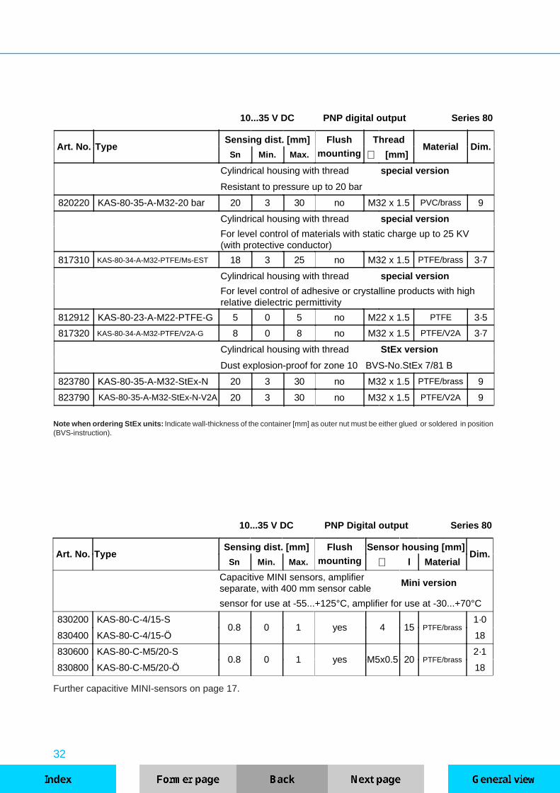
10...35 V DC PNP Digital output Series 80
Art. No. TypeSensing dist. [mm] Flush Sensor housing [mm]
Dim.Sn Min. Max. mounting ∅ l Material
Capacitive MINI sensors, amplifierseparate, with 400 mm sensor cable
Mini version
sensor for use at -55...+125°C, amplifier for use at -30...+70°C
830200 KAS-80-C-4/15-S0.8 0 1 yes 4 15 PTFE/brass
1·0
830400 KAS-80-C-4/15-Ö 18
830600 KAS-80-C-M5/20-S0.8 0 1 yes M5x0.5 20 PTFE/brass
2·1
830800 KAS-80-C-M5/20-Ö 18
Further capacitive MINI-sensors on page 17.
10...35 V DC PNP digital output Series 80
Art. No. TypeSensing dist. [mm] Flush Thread
Material Dim.Sn Min. Max. mounting ∅ [mm]
Cylindrical housing with thread special version
Resistant to pressure up to 20 bar
820220 KAS-80-35-A-M32-20 bar 20 3 30 no M32 x 1.5 PVC/brass 9
Cylindrical housing with thread special version
For level control of materials with static charge up to 25 KV(with protective conductor)
817310 KAS-80-34-A-M32-PTFE/Ms-EST 18 3 25 no M32 x 1.5 PTFE/brass 3·7
Cylindrical housing with thread special version
For level control of adhesive or crystalline products with highrelative dielectric permittivity
812912 KAS-80-23-A-M22-PTFE-G 5 0 5 no M22 x 1.5 PTFE 3·5
817320 KAS-80-34-A-M32-PTFE/V2A-G 8 0 8 no M32 x 1.5 PTFE/V2A 3·7
Cylindrical housing with thread StEx version
Dust explosion-proof for zone 10 BVS-No.StEx 7/81 B
823780 KAS-80-35-A-M32-StEx-N 20 3 30 no M32 x 1.5 PTFE/brass 9
823790 KAS-80-35-A-M32-StEx-N-V2A 20 3 30 no M32 x 1.5 PTFE/V2A 9
Note when ordering StEx units: Indicate wall-thickness of the container [mm] as outer nut must be either glued or soldered in position(BVS-instruction).

33
For suitable mounting clamps please refer to our catalogue of accessories.
15...30V DCAnalog output
4...20mASeries 80
Art. No. TypeWorking- Linear- Flush Thread
Material Dim.range [mm] mounting ∅ [mm]
Cylindrical housing with thread Analog version
Housing with standard thread
800400 KAS-80-A12-IL 0…5 0…3.5 yes M12 x 1 PTFE/brass 2·6
801600 KAS-80-A13-IL 0…8 0…5 yes M18 x 1 PTFE/brass 2·7
806400 KAS-80-A14-IL 0…20 0…14 yes M30 x 1.5 PTFE/brass 2·8
Cylindrical housing with thread Analog version
816600 KAS-80-30-IL-M32 0…30 0...20 yes M32 x 1.5 PTFE/brass 2·9
818300 KAS-80-34-IL-M32-PTFE/Ms 0…35 0…25 no M32 x 1.5 PTFE/brass 3·7
Cylindrical housing Analog version
812200 KAS-80-20-IL 0...10 0...7 yes 22 PTFE/brass 1·7
815000 KAS-80-30-IL 0...30 0...20 yes 30 PTFE/brass 1·8
827100 KAS-80-50-IL 0...40 0...30 yes 50 PA 1·11
Cylindrical housing with thread Analog version
with metal flange connector M12 x 1
806500 KAS-80-A14-IL-Y5 0…20 0…14 yes M30 x 1.5 PTFE/brass 6·4
816700 KAS-80-30-IL-M32-Y5 0…30 0...20 yes M32 x 1.5 PTFE/brass 6·6
815100 KAS-80-30-IL-Y5 0...30 0...20 yes 30 PTFE/brass 8

34
Technical data Compact 160KAS with digital output
Housing / active area ∅∅ ≥≥ 30 mm M 32 x 1.5
Operating voltage 10…35 V DCRated voltage Un 24 V DCResidual ripple max. 10 %No-load current Io typ. 15 mAOutput current max. (NO+NC) Ie 400 mAVoltage drop. max. Ud 2.5 VFrequency of operating cycles max. 800 HzSwitching hysteresis < 10 %Repeat accuracy < 0.1 %
Drift < 10 %Permitted ambient temperature -25…+70°C -Permitted media temperature -25…+70°C -60...+160°C (at sensor head)
Permitted surface temperatureelectronic
-25…+70°C -25...+70°C (thread-free part)
LED indication green built-in / stand by
LED indication yellow built-in / active area damped
Overload protection built-inElectr. short-circuit protection built-inReverse polarity protection built-in
Degree of protection IEC 529 IP 67
Connection cable 3-wire 2m 3 x 0.75 mm²Data at +24°C, = 24V DC
TECHNICAL DATA - SERIES 2000
UB
Switching functions:
Switch position 1 NPN-NO Active area free: 0-Signal Active area covered: 1-Signal / negative potential
PNP-NC Active area free: 1-Signal / positive potential Active area covered: 0-Signal
Switch position 0 NPN-NC Active area free: 1-Signal / negative potential Active area covered: 0-Signal
PNP-NO Active area free: 0-Signal Active area covered: 1-Signal / positive potential
The series 2000 quattro+3 contains capacitive 3-wire proximity sensors with four output-functions , NPN-NO and PNP-NC or, after resetting of the coding switch, NPN-NC and PNP-NO. Electronic circuits, PLC‘s,relays and our power supplies of series 130 can be activated directly. Different housing materials areavailable, such as PA, PTFE, PTFE/brass or PTFE/V2A. This series is completed by a version for mediumtemperatures up to +160°C.
UB

35
0
1
TYPES - SERIES 2000
For suitable mounting clamps please refer to our catalogue of accessories.
Sealing screwChange-over switch
Sealing screw,Potentiometer
LED green
LED yellow
The change-over switch and potentiometer can be altered afterremoving the plastic sealing screw. The switching function has to beconverted at the change-over switch by means of the enclosed screwdriver, Position 1 (factory set) or 0.
10...35 V DCNPN/PNP/NO/NC-
Digital outputSeries 2000
Art. No. TypeSensing dist. [mm] Flush Thread
Material Dim.Sn Min. Max. mounting ∅ [mm]
Cylindrical housing with thread DIN VDE 0660 Part 208
770100 KAS-2000-A14 10 2 20 yes M30 x 1.5 PTFE/brass 2·8
770200 KAS-2000-A24 15 3 25 no M30 x 1.5 PTFE/brass 3·6
770250 KAS-2000-A24-K 15 3 25 no M30 x 1.5 PA 3·6
Cylindrical housing with thread
770600 KAS-2000-30-M32 20 2 25 yes M32 x 1.5 PA/brass 2·9
770800 KAS-2000-35-M32 25 3 30 no M32 x 1.5 PA 3·7
770900 KAS-2000-34-M32-PTFE/Ms 25 3 30 no M32 x 1.5 PTFE/brass 3·7
771000 KAS-2000-34-M32-PTFE/V2A 25 3 30 no M32 x 1.5 PTFE/V2A 3·7
Cylindrical housing
770500 KAS-2000-30 20 2 25 yes 30 PA/brass 1·8
770700 KAS-2000-35 25 3 30 no 30 PA 1·8
10...35 V DCNPN/PNP/NO/NC
Digital outputSeries 2000
Art. No. TypeSensing dist. [mm] Flush Thread
Material Dim.Sn Min. Max. mounting ∅ [mm]
Cylindrical housing with thread Compact 160
for medium temperatures of: - 60...+160°C
771100 KAS-2000-34-M32-PTFE/V2A-160°C 15 2 20 no M32 x 1.5 PTFE/V2A 14
771200 KAS-2000-35-M32-PTFE-160°C 15 2 20 no M32 x 1.5 PTFE 14

36
Technical data StandardKAS with digital output
Housing / active area ∅∅ 18...64 mm
Operating voltage 20…250 V AC
Rated voltage Un 120 V AC 230 V AC
No-load current Io typ. 2.5 mA typ. 2.5 mA
Output current min. Ie typ. 5 mA typ. 5 mA
Output current max. Ie 330 mA 330 mA
Voltage drop max. Ud typ. 6 V
Frequency of operating cycles max. 25 Hz
Switching hysteresis typ. 10 %
Repeat accuracy typ. 0.1 %
Drift < 10%
Permitted ambient temperature -25…+70°C
LED indication yellow built-in
Degree of protection according to IEC 529 IP 67
Connection cablePlastic housing 2m 2 x 0.34 mm²/0.75 mm²
Metal housing 2m 3 x 0.75mm²
Data at +24°C, = 120/230 V AC
TECHNICAL DATA - SERIES 90
Switching functions:S = NO Active surface free: 0-Signal
Active surface covered: 1-SignalÖ = NC Active surface free: 1-Signal
Active surface covered: 0-Signal
The series 90 contains capacitive 2-wire AC proximity sensors with digital output with NO and NC function.AC relays, conductors, solenoid valves can be activated directly. PLCs with AC inputs can also be con-nected if the minimum load current is taken into consideration. The sensors have a protective circuit againsthigh induction voltages.
UB
UB
37
TYPES - SERIES 90
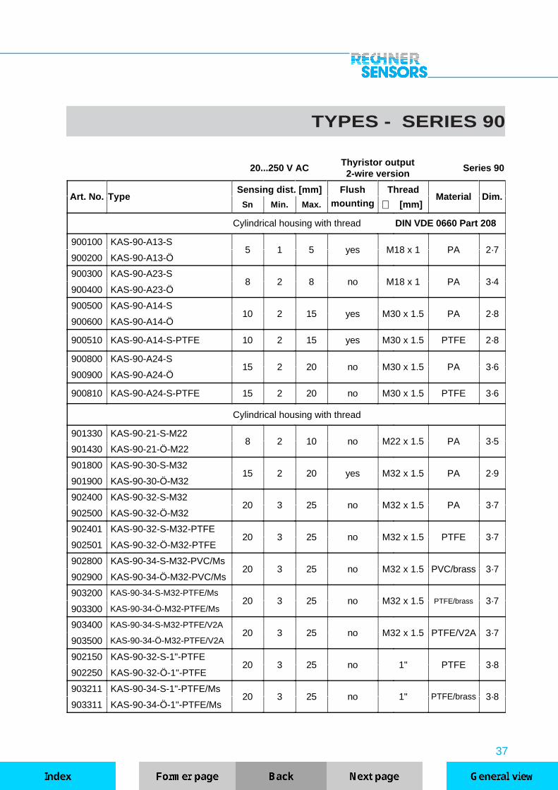
20...250 V ACThyristor output2-wire version
Series 90
Art. No. TypeSensing dist. [mm] Flush Thread
Material Dim.Sn Min. Max. mounting ∅ [mm]
Cylindrical housing with thread DIN VDE 0660 Part 208
900100 KAS-90-A13-S5 1 5 yes M18 x 1 PA 2·7
900200 KAS-90-A13-Ö
900300 KAS-90-A23-S8 2 8 no M18 x 1 PA 3·4
900400 KAS-90-A23-Ö
900500 KAS-90-A14-S10 2 15 yes M30 x 1.5 PA 2·8
900600 KAS-90-A14-Ö
900510 KAS-90-A14-S-PTFE 10 2 15 yes M30 x 1.5 PTFE 2·8
900800 KAS-90-A24-S15 2 20 no M30 x 1.5 PA 3·6
900900 KAS-90-A24-Ö
900810 KAS-90-A24-S-PTFE 15 2 20 no M30 x 1.5 PTFE 3·6
Cylindrical housing with thread
901330 KAS-90-21-S-M228 2 10 no M22 x 1.5 PA 3·5
901430 KAS-90-21-Ö-M22
901800 KAS-90-30-S-M3215 2 20 yes M32 x 1.5 PA 2·9
901900 KAS-90-30-Ö-M32
902400 KAS-90-32-S-M3220 3 25 no M32 x 1.5 PA 3·7
902500 KAS-90-32-Ö-M32
902401 KAS-90-32-S-M32-PTFE20 3 25 no M32 x 1.5 PTFE 3·7
902501 KAS-90-32-Ö-M32-PTFE
902800 KAS-90-34-S-M32-PVC/Ms20 3 25 no M32 x 1.5 PVC/brass 3·7
902900 KAS-90-34-Ö-M32-PVC/Ms
903200 KAS-90-34-S-M32-PTFE/Ms20 3 25 no M32 x 1.5 PTFE/brass 3·7
903300 KAS-90-34-Ö-M32-PTFE/Ms
903400 KAS-90-34-S-M32-PTFE/V2A20 3 25 no M32 x 1.5 PTFE/V2A 3·7
903500 KAS-90-34-Ö-M32-PTFE/V2A
902150 KAS-90-32-S-1"-PTFE20 3 25 no 1" PTFE 3·8
902250 KAS-90-32-Ö-1"-PTFE
903211 KAS-90-34-S-1"-PTFE/Ms20 3 25 no 1" PTFE/brass 3·8
903311 KAS-90-34-Ö-1"-PTFE/Ms
38
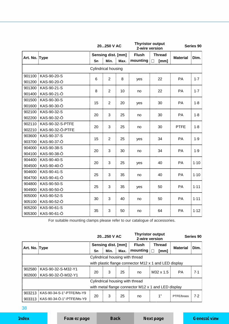
20...250 V ACThyristor output2-wire version
Series 90
Art. No. TypeSensing dist. [mm] Flush Thread
Material Dim.Sn Min. Max. mounting ∅ [mm]
Cylindrical housing
901100 KAS-90-20-S6 2 8 yes 22 PA 1·7
901200 KAS-90-20-Ö
901300 KAS-90-21-S8 2 10 no 22 PA 1·7
901400 KAS-90-21-Ö
901500 KAS-90-30-S15 2 20 yes 30 PA 1·8
901600 KAS-90-30-Ö
902100 KAS-90-32-S20 3 25 no 30 PA 1·8
902200 KAS-90-32-Ö
902110 KAS-90-32-S-PTFE20 3 25 no 30 PTFE 1·8
902210 KAS-90-32-Ö-PTFE
903600 KAS-90-37-S15 2 25 yes 34 PA 1·9
903700 KAS-90-37-Ö
904000 KAS-90-38-S20 3 30 no 34 PA 1·9
904100 KAS-90-38-Ö
904400 KAS-90-40-S20 3 25 yes 40 PA 1·10
904500 KAS-90-40-Ö
904600 KAS-90-41-S25 3 35 no 40 PA 1·10
904700 KAS-90-41-Ö
904800 KAS-90-50-S25 3 35 yes 50 PA 1·11
904900 KAS-90-50-Ö
905000 KAS-90-52-S30 3 40 no 50 PA 1·11
905100 KAS-90-52-Ö
905200 KAS-90-61-S35 3 50 no 64 PA 1·12
905300 KAS-90-61-Ö
20...250 V ACThyristor output2-wire version
Series 90
Art. No. TypeSensing dist. [mm] Flush Thread
Material Dim.Sn Min. Max. mounting ∅ [mm]
Cylindrical housing with thread
with plastic flange connector M12 x 1 and LED display
902580 KAS-90-32-S-M32-Y120 3 25 no M32 x 1.5 PA 7·1
902600 KAS-90-32-Ö-M32-Y1
Cylindrical housing with thread
with metal flange connector M12 x 1 and LED display
903213 KAS-90-34-S-1"-PTFE/Ms-Y920 3 25 no 1" PTFE/brass 7·2
903313 KAS-90-34-Ö-1"-PTFE/Ms-Y9
For suitable mounting clamps please refer to our catalogue of accessories.

39
TECHNICAL DATA - SERIES 1000
UB
UB
Switching functions:
Switch position 1 NO Active area free: 0-SignalActive area covered: 1-Signal
Switch position 0 NC Active area free: 1-SignalActive area covered: 0-Signal
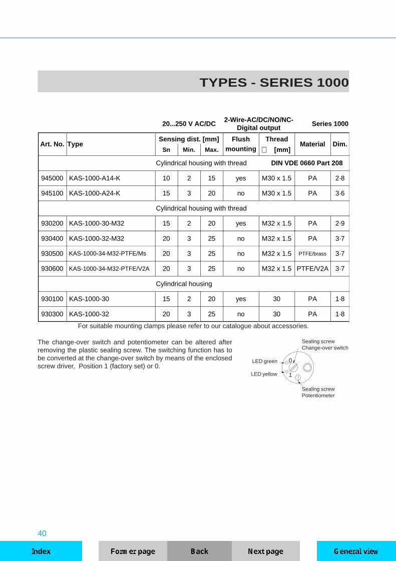
The series 1000 duo~2 contains capacitive 2-wire a.c.-d.c. proximity sensors with NO and NC-function.The supply voltage range of 20...250 V AC/DC allows the application in electronic circuits, PLC‘s as wellas for conductors with AC supply voltage. The output functions (NO or NC) can be determined by meansof a coding switch. The available housing materials are PA, PTFE/brass or PTFE/V2A.
Technical dataKAS with digital output
Housing / active area ∅∅ ≥≥ 30mm
Operating voltage 20…250 V AC 20...250 V DC
Rated voltage Un 230 V AC 24 V DC
No-load current Io typ. 2 mA typ. 2 mA
Output current min. Ie typ.5 mA typ. 5 mA
Output current max. Ie 500 mA 500 mA
Voltage drop max. Ud typ. 6 V
Frequency of operating cycles max. 25 Hz
Switching hysteresis typ. 10 %
Repeat accuracy typ. 0.1 %
Drift < 10 %
Permitted ambient temperature -25…+70 °C
LED indication yellow built-in
Degree of protection IEC 529 IP 67
Connection cablePlastic housing 2m 2 x 0.75 mm²
Metal housing 2m 3 x 0.75mm²
Data at +24°C, = 230 V AC or 24 V DC
40
0
1
LED green
LED yellow
TYPES - SERIES 1000
The change-over switch and potentiometer can be altered afterremoving the plastic sealing screw. The switching function has tobe converted at the change-over switch by means of the enclosedscrew driver, Position 1 (factory set) or 0.
Sealing screwPotentiometer
For suitable mounting clamps please refer to our catalogue about accessories.
20...250 V AC/DC2-Wire-AC/DC/NO/NC-
Digital outputSeries 1000
Art. No. TypeSensing dist. [mm] Flush Thread
Material Dim.Sn Min. Max. mounting ∅ [mm]
Cylindrical housing with thread DIN VDE 0660 Part 208
945000 KAS-1000-A14-K 10 2 15 yes M30 x 1.5 PA 2·8
945100 KAS-1000-A24-K 15 3 20 no M30 x 1.5 PA 3·6
Cylindrical housing with thread
930200 KAS-1000-30-M32 15 2 20 yes M32 x 1.5 PA 2·9
930400 KAS-1000-32-M32 20 3 25 no M32 x 1.5 PA 3·7
930500 KAS-1000-34-M32-PTFE/Ms 20 3 25 no M32 x 1.5 PTFE/brass 3·7
930600 KAS-1000-34-M32-PTFE/V2A 20 3 25 no M32 x 1.5 PTFE/V2A 3·7
Cylindrical housing
930100 KAS-1000-30 15 2 20 yes 30 PA 1·8
930300 KAS-1000-32 20 3 25 no 30 PA 1·8
Sealing screwChange-over switch

41
TEMPERATURE - RESISTANT KAS
UB
UB
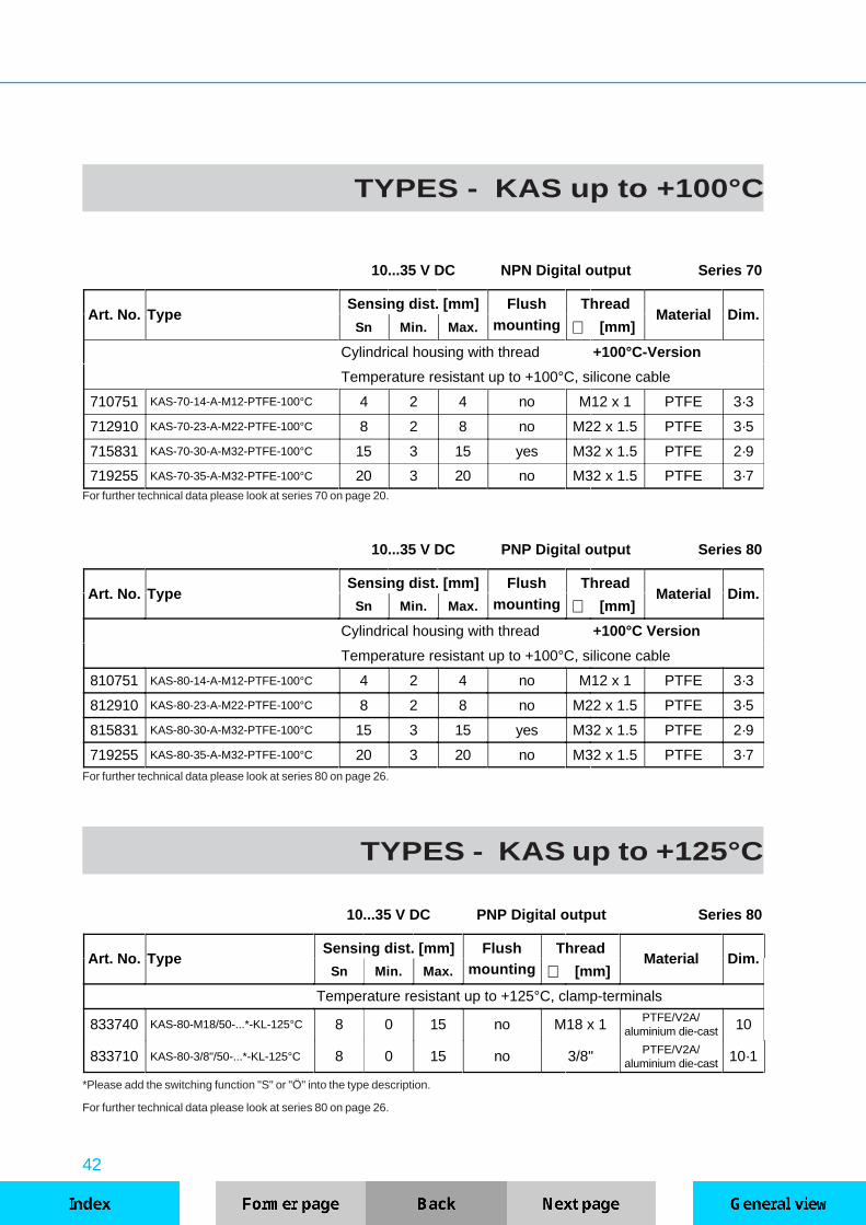
For increased requirements for the permitted ambient temperature range of our capacitive proximity sen-sors, we offer the series up to +100°C with integrated electronic as a 3-Wire DC version (see series 70 and80). The sensors are available with housings made of PTFE, PTFE/V2A or PTFE/brass and have a siliconeconnection cable. Sensors with quattro+3 or NAMUR-output are available for temperatures up to +160°C(medium) or +180°C (see series 2000 and 40). Here too housing materials PTFE and V2A are used asstandard. For extreme ambient or product-temperature conditions, our high temperature sensors up to +250°Cwith external electronics are available. The sensors are integrated in PTFE or PTFE/V2A housings. TheFEP-coated sensor cable, in the lengths 2 and 5 m, is the connection to the evaluation unit and may also beused under high-temperature conditions. The evaluation unit is connected to the sensor by means of a plug-in connector. On the sensor side the cable is permanently cast in or equipped with a temperature-resistantplug-in connector (...Y-version). The sensing distance for high temperature sensors can be adjusted on theevaluation unit and the switching state is displayed by a LED. The sensing distance adjustment should bemade at operating temperature. Here the maximum specified sensing distance and the temperature drivemust be taken into consideration.
Technical data +250°CKAS temperature resistant
Type KS-250-M... KSA-250 KSA-...-BBKAS-...-BB
Operating voltage - 200...240 V AC 10...35 V DCRated voltage Un - 230 V AC 24 V DC
Residual ripple max. - - 10 %No-load current Io - typ. 16 mA typ. 10 mAContacts output relay - 1 Change-over -
Contact rating - 250V/6A/500VA -Output current max. Ie - - 400 mAVoltage drop max. Ud - - 2.5 V
Frequency of operating cycles max. - - 80 HzSwitching hysteresis - typ. 10 % typ. 10 %Repeat accuracy - < 0.1 % < 0.1%Drift - typ. 10 % typ. 10 %Permitted ambient temperature -200...+250°C -20...+60°C -25...+70°C
LED indication red - built-in built-inOverload protection - - built-inElectr. short-circuit protection - - built-in
Reverse polarity protection - - built-inDegree of protection IEC 529 IP 67 IP 40 / IP 20 IP 67
Connection cable 2 m FEP Terminals 2 m 3 x 0.14mm²
Data at +24°C, = 24V DC or 230 V AC
42
TYPES - KAS up to +100°C
10...35 V DC NPN Digital output Series 70
Art. No. TypeSensing dist. [mm] Flush Thread
Material Dim.Sn Min. Max. mounting ∅ [mm]
Cylindrical housing with thread +100°C-Version
Temperature resistant up to +100°C, silicone cable
710751 KAS-70-14-A-M12-PTFE-100°C 4 2 4 no M12 x 1 PTFE 3·3
712910 KAS-70-23-A-M22-PTFE-100°C 8 2 8 no M22 x 1.5 PTFE 3·5
715831 KAS-70-30-A-M32-PTFE-100°C 15 3 15 yes M32 x 1.5 PTFE 2·9
719255 KAS-70-35-A-M32-PTFE-100°C 20 3 20 no M32 x 1.5 PTFE 3·7For further technical data please look at series 70 on page 20.
10...35 V DC PNP Digital output Series 80
Art. No. TypeSensing dist. [mm] Flush Thread
Material Dim.Sn Min. Max. mounting ∅ [mm]
Cylindrical housing with thread +100°C Version
Temperature resistant up to +100°C, silicone cable
810751 KAS-80-14-A-M12-PTFE-100°C 4 2 4 no M12 x 1 PTFE 3·3
812910 KAS-80-23-A-M22-PTFE-100°C 8 2 8 no M22 x 1.5 PTFE 3·5
815831 KAS-80-30-A-M32-PTFE-100°C 15 3 15 yes M32 x 1.5 PTFE 2·9
719255 KAS-80-35-A-M32-PTFE-100°C 20 3 20 no M32 x 1.5 PTFE 3·7For further technical data please look at series 80 on page 26.
TYPES - KAS up to +125°C
10...35 V DC PNP Digital output Series 80
Art. No. TypeSensing dist. [mm] Flush Thread
Material Dim.Sn Min. Max. mounting ∅ [mm]
Temperature resistant up to +125°C, clamp-terminals
833740 KAS-80-M18/50-...*-KL-125°C 8 0 15 no M18 x 1 PTFE/V2A/aluminium die-cast 10
833710 KAS-80-3/8"/50-...*-KL-125°C 8 0 15 no 3/8" PTFE/V2A/aluminium die-cast 10·1
*Please add the switching function "S" or "Ö" into the type description.
For further technical data please look at series 80 on page 26.
43
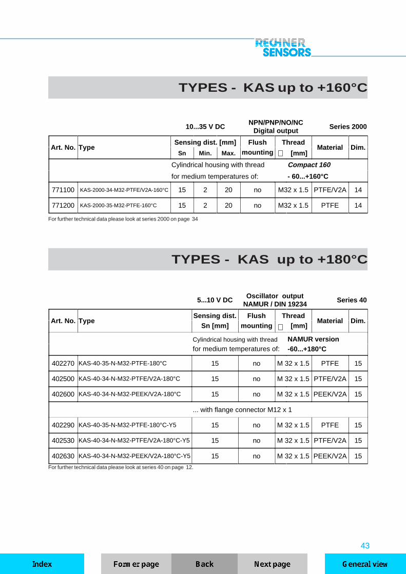
TYPES - KAS up to +160°C
For further technical data please look at series 2000 on page 34
10...35 V DCNPN/PNP/NO/NC
Digital outputSeries 2000
Art. No. TypeSensing dist. [mm] Flush Thread
Material Dim.Sn Min. Max. mounting ∅ [mm]
Cylindrical housing with thread Compact 160
for medium temperatures of: - 60...+160°C
771100 KAS-2000-34-M32-PTFE/V2A-160°C 15 2 20 no M32 x 1.5 PTFE/V2A 14
771200 KAS-2000-35-M32-PTFE-160°C 15 2 20 no M32 x 1.5 PTFE 14
TYPES - KAS up to +180°C
5...10 V DCOscillator output
NAMUR / DIN 19234Series 40
Art. No. TypeSensing dist. Flush Thread
Material Dim.Sn [mm] mounting ∅ [mm]
Cylindrical housing with thread NAMUR versionfor medium temperatures of: -60...+180°C
402270 KAS-40-35-N-M32-PTFE-180°C 15 no M 32 x 1.5 PTFE 15
402500 KAS-40-34-N-M32-PTFE/V2A-180°C 15 no M 32 x 1.5 PTFE/V2A 15
402600 KAS-40-34-N-M32-PEEK/V2A-180°C 15 no M 32 x 1.5 PEEK/V2A 15
... with flange connector M12 x 1
402290 KAS-40-35-N-M32-PTFE-180°C-Y5 15 no M 32 x 1.5 PTFE 15
402530 KAS-40-34-N-M32-PTFE/V2A-180°C-Y5 15 no M 32 x 1.5 PTFE/V2A 15
402630 KAS-40-34-N-M32-PEEK/V2A-180°C-Y5 15 no M 32 x 1.5 PEEK/V2A 15
For further technical data please look at series 40 on page 12.

44
TYPES - KAS up to +250°C
High-Temperature Sensors forconnection to amplifiers KSA...
Series 250
Art. No. TypeSensing dist. [mm] Flush Thread
Material Dim.Sn Min. Max. mounting ∅ [mm]
Cylindrical housing with thread, high-temperature version
for use at -200…+250°C, 2 m sensor cable FEP,
amplifier/evaluation unit separate from the sensor, pluggable.
562100 KS-250-M22 6 2 10 no M22 x 1.5 PTFE/V2A 16·1
562200 KS-250-M22-PTFE 6 2 10 no M22 x 1.5 PTFE 16·1
562500 KS-250-M32 12 3 20 no M32 x 1.5 PTFE/V2A 16·2
562520 KS-250-M32-PTFE 12 3 20 no M32 x 1.5 PTFE 16·2
... with flange connector (IP 67, temperature resistant) at Sensor
562300 KS-250-M22-Y 6 2 10 no M22 x 1.5 PTFE/V2A 16·1
562700 KS-250-M32-Y 12 3 20 no M32 x 1.5 PTFE/V2A 16·2
Amplifiers for capacitive high-temperature sensors KS...M 22 x 1.5...M 32 x 1.5
Art. No. Type Operating voltage Output relay Output / Function Dim.
560100 KSA-250 240 V AC 1 change-over - 21
560101 KSA-250 120 V AC 1 change-over - 21
560700 KSA-70-250-S-BB 10...35 V DC - NPN / NO 20
560900 KSA-70-250-Ö-BB 10...35 V DC - NPN / NC 20
561100 KSA-80-250-S-BB 10...35 V DC - PNP / NO 20
561300 KSA-80-250-Ö-BB 10...35 V DC - PNP / NC 20

45
Amplifiers for capacitive high-temperature sensors KS...M 18 x 1
Art. No. Type Operating voltageHysteresisadjustable
Output / Function Dim.
563100 KAS-70-14-M18/30-S-BB 10...35 V DC yes NPN / NO 19
563300 KAS-70-14-M18/30-Ö-BB 10...35 V DC yes NPN / NC 19
563500 KAS-80-14-M18/30-S-BB 10...35 V DC yes PNP / NO 19
563700 KAS-80-14-M18/30-Ö-BB 10...35 V DC yes PNP / NC 19
High-temperature sensors forconnection to amplifiers KAS..BB
Series 250
Art. No. TypeSensing dist. [mm] Flush Thread
Material Dim.Sn Min. Max. mounting ∅ [mm]
Cylindrical housing with thread, high-temperature sensors
for use at -200…+250°C, 0,8 m sensor cable FEP,
amplifier/evaluation unit seperate from the sensor, pluggable.
561600 KS-250-M18/30 3 0 5 no M18 x 1 PTFE/V2A 17·1
561650 KS-250-M18/45 3 0 5 no M18 x 1 PTFE/V2A 17·2

46
DIMENSIONSd
l
Dim. 1
Dimension Diameter Length Dimension Diameter Length
No. d [mm] l [mm] No. d [mm] l [mm]
1·0 4 15 1·6 20 70
1·01 6.0 15 1·7 22 70
1·1 6.5 15 1·8 30 70
1·2 6.5 20 1·9 34 80
1·3 10 20 1·10 40 70
1·4 11 50 1·11 50 70
1·5 11 70 1·12 64 70
47
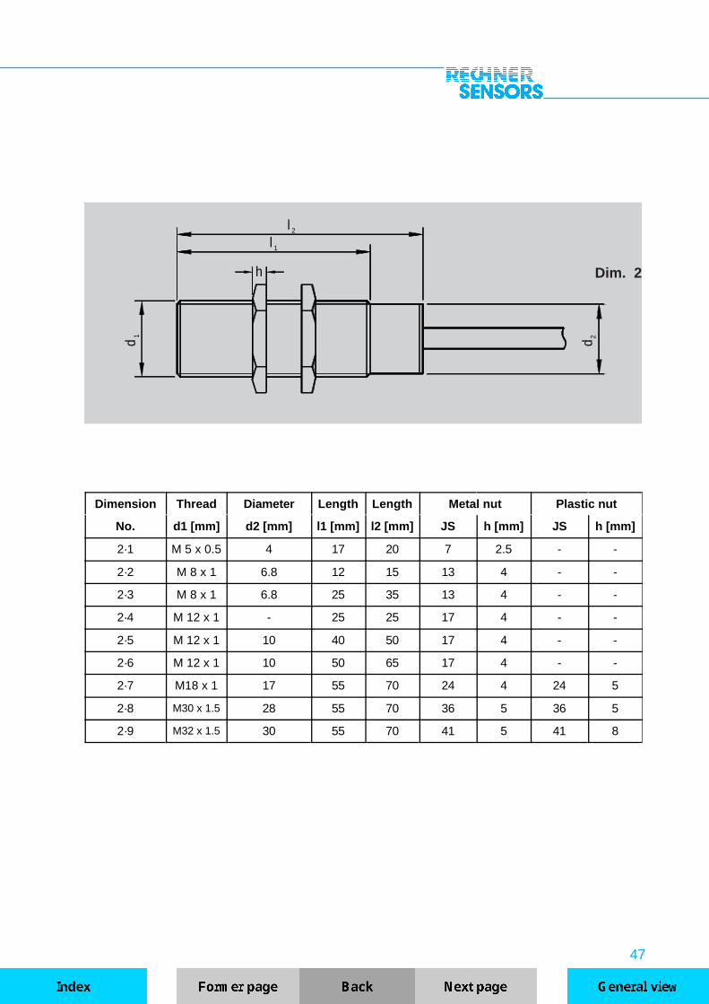
d1
l
h
l
1
2
d 2
Dim. 2
Dimension Thread Diameter Length Length Metal nut Plastic nut
No. d1 [mm] d2 [mm] l1 [mm] l2 [mm] JS h [mm] JS h [mm]
2·1 M 5 x 0.5 4 17 20 7 2.5 - -
2·2 M 8 x 1 6.8 12 15 13 4 - -
2·3 M 8 x 1 6.8 25 35 13 4 - -
2·4 M 12 x 1 - 25 25 17 4 - -
2·5 M 12 x 1 10 40 50 17 4 - -
2·6 M 12 x 1 10 50 65 17 4 - -
2·7 M18 x 1 17 55 70 24 4 24 5
2·8 M30 x 1.5 28 55 70 36 5 36 5
2·9 M32 x 1.5 30 55 70 41 5 41 8
48
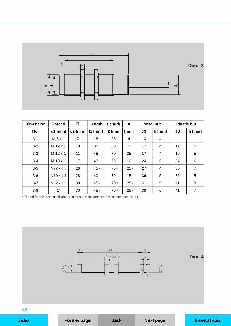
d1
d2
l
hX
l
1
2
d 2
Dim. 3
Dim. 4
* Thread-free area not applicable, that means measurement l2 = measurement l1 + x.
* * *
* * *
* * *
Dimension Thread ∅∅ Length Length X Metal nut Plastic nut
No. d1 [mm] d2 [mm] l1 [mm] l2 [mm] [mm] JS h [mm] JS h [mm]
3·1 M 8 x 1 7 18 25 4 13 4 - -
3·2 M 12 x 1 10 35 50 5 17 4 17 5
3·3 M 12 x 1 11 45 70 25 17 4 19 5
3·4 M 18 x 1 17 43 70 12 24 5 24 6
3·5 M22 x 1.5 20 45 70 25 27 4 30 7
3·6 M30 x 1.5 28 40 70 15 36 5 36 5
3·7 M32 x 1.5 30 45 70 25 41 5 41 8
3·8 1" 30 45 70 25 38 6 41 7

49
Dim. 6
For non-flush mountable sensorsthe thread l1 is shorter by theamount X.
d 1
X
l 2
1l
h
2d
l 3
Dim. 5
Dimension Thread Length X Metal nut
No. d1 d2 l1 [mm] l2 [mm] l3 [mm] [mm] JS h [mm]
5·1 M 12 x 1 M 12 x 1 40 60 10 - 13 4
5·2 M 12 x 1 M 12 x 1 40 60 10 5 13 4
Dimension Thread Length X Nut
No. d1 d2 l1[mm]
l2[mm]
l3[mm] [mm
Material JS h [mm]
6·1 M 18 x 1 M 12 x 1 55 70 15 - Brass 24 4
6·2 M 18 x 1 M 12 x 1 55 70 15 12 Brass 24 4
6·3 M 18 x 1 M 12 x 1 55 70 15 12 PA 24 6
6·4 M 30 x 1.5 M 12 x 1 55 70 15 - Brass 36 5
6·5 M 30 x 1.5 M 12 x 1 55 70 15 15 Brass 36 5
6·6 M 32 x 1.5 M 12 x 1 55 70 15 - Brass 41 5
For non-flush mountable sensors the thread l1 is shorter by the amount X.

50
Dim. 7
Dim. 9
Dim. 8
Dimension ∅∅ Thread Length Nut
No. d1 d2 d3 l1[mm]
l2[mm]
l3[mm]
Material JS h [mm]
7·1 30 M32x1.5 M12x1 25 70 15 PA 41 5
7·2 30 1" M12x1 25 70 15 Brass 38 6

51
Dim. 10
Dim. 11active surface
10
121
SW27
50
ø12
M18 x 1
12
57
PG9
ASL
POTI
+_
LED
10
121
SW27
50
ø12
3/8"
12
57
PG9
ASL
POTI
+_
LED
Connection of theclamp terminals
Connection of theclamp terminals
Dim. 10.1
52
0
1
LED green
LED yellow
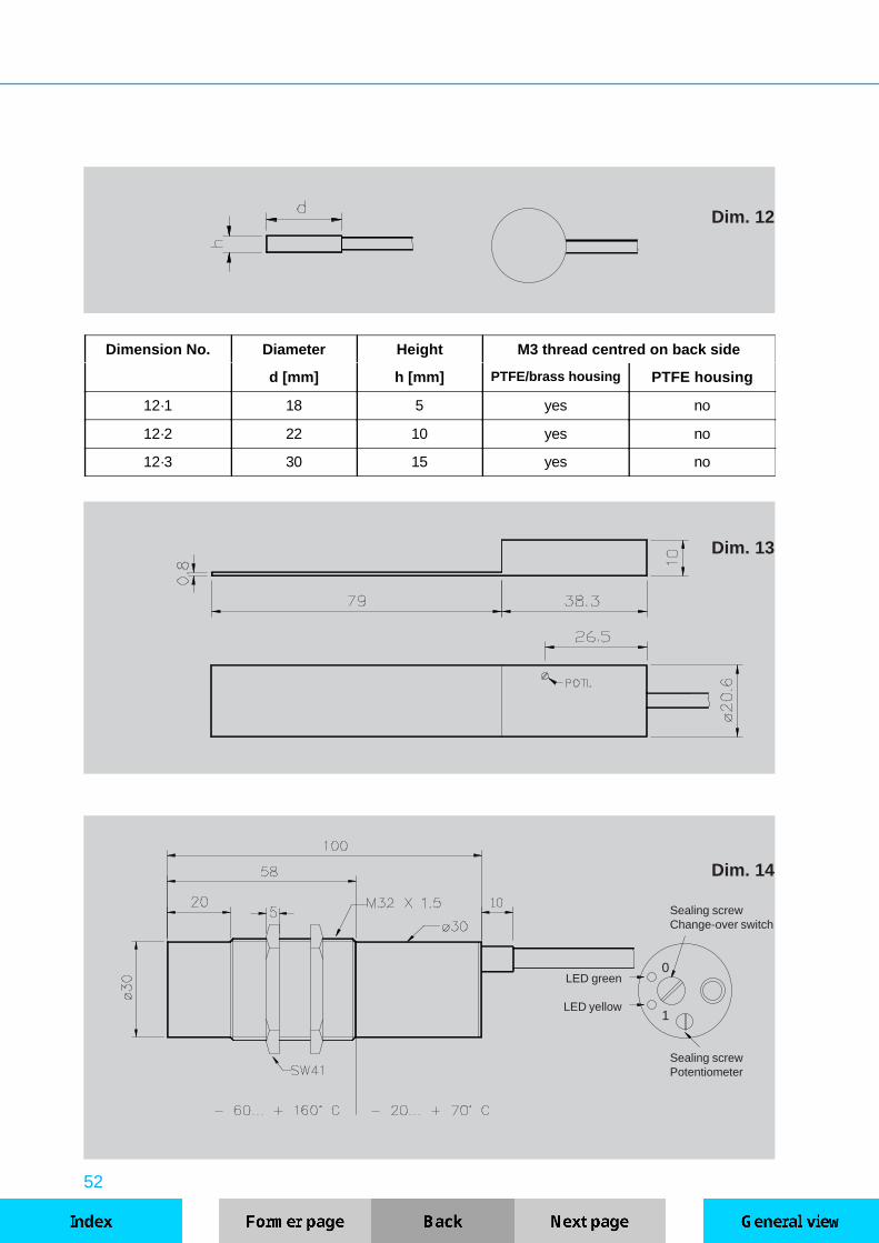
Dim. 12
Dim. 13
Sealing screwPotentiometer
Dim. 14
Sealing screwChange-over switch
Dimension No. Diameter Height M3 thread centred on back side
d [mm] h [mm] PTFE/brass housing PTFE housing
12·1 18 5 yes no
12·2 22 10 yes no
12·3 30 15 yes no

53
Plug-in connectionwith Y-version only
Dim. 15
Dim. 16
pluggable version Y5
Dimension ∅∅ Thread Length [mm] Screw Stainless steel nut
No. d1 [mm] d2 l1 l2 JS b [mm] JS h [mm]
16·1 20 M22 x 1.5 25 70 19 5 27 4
16·2 30 M32 x 1.5 25 70 24 5 41 5
Connecting piece for protectivehose. For cable version only.

54
Dim. 17
4xM3Inlets
POTI Hy
50
15
20
LED POTI Sn
6.6
1525
35
15
50
Dim. 19
Dim. 18
SW17
ø16
M18
x1
ø14
ø2032l
6
l
4
1
ø11.5SW8
23.5MB l1 [mm] l2 [mm]
17·1 30 15
17·2 45 30
Sensor cablepermanently cast in.
Male connectorfor HT-SensorM 18 x 1

55
Dim. 20
Dim. 21
Mal
e co
nnec
tor
for
HT
-Sen
sor
M 2
2 an
d M
32
Male connectorfor HT-SensorM 22 x 1,5M 32 x 1,5