catalogue heating, air-conditioning, cooling glandless … circulation... · ssm fault signal or...
TRANSCRIPT
Glandless Circulators
and Accessories,
Package Heat Exchanger Assembly
Catalogue Heating, Air-Conditioning, Cooling
Glandless Pumps
Catalogue A1 - 50 Hz - 2007 A1
7
1
2
35
4
6
8
9
10
13
12
11
Wilo-Jet WJ
B1
1
Wilo-SubTW5/TW5-SE
B1
2
Wilo-SilentMaster
B1
3
Wilo-Sub TWU 3
B1
4
Wilo-RainSystemAF Comfort
B1
5
Wilo-Comfort-Vario CO 1/MVIE
B4
6
Wilo-Comfort-Vario CO 1/MVIE
B4
6
Wilo-EasyStar
A1
7
Wilo-Safe
A1
8
Wilo-Star-Z 15 TT
A1
9
Wilo-DrainLift Con
C3
10
Wilo-Stratos
A1
11
Wilo-Drain TM/TMW 32 Twister
C1
12
Wilo-DrainLift S
C3
13
SeriesCatalogue
Wilo-EMU KS
C1
1
Wilo-RainSystemAF 150
B1
2
Wilo-Comfort-VarioCOR 3/MHIE VR
B4
3
Wilo-Stratos-D
A1
4
Wilo-CronoLine-IL-E
A2
5
Wilo-TOP-Z
A1
6
Wilo-Stratos-Z
A1
7
Wilo-CronoBloc-BL
A3
8
Wilo-CronoBloc-BL
A3
8
Wilo-DrainLift M
C3
9
Wilo-DrainLift WS
C3
10
Wilo-VeroNorm-NP/NPG
A3
11
7
1
2
3
6
5
89
104
11
SeriesCatalogue
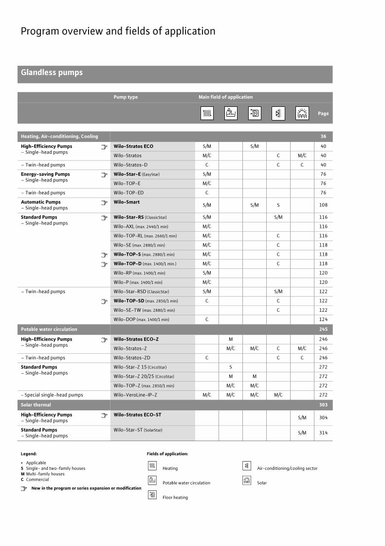
Program overview and fields of application
Glandless pumps
Pump type Main field of application
Page
Heating, Air-conditioning, Cooling 36
High-Efficiency Pumps– Single-head pumps
Wilo-Stratos ECO S/M S/M 40
Wilo-Stratos M/C C M/C 40
– Twin-head pumps Wilo-Stratos-D C C C 40
Energy-saving Pumps– Single-head pumps
Wilo-Star-E (EasyStar) S/M 76
Wilo-TOP-E M/C 76
– Twin-head pumps Wilo-TOP-ED C 76
Automatic Pumps– Single-head pumps
Wilo-Smart S/M S/M S 108
Standard Pumps– Single-head pumps
Wilo-Star-RS (ClassicStar) S/M S/M 116
Wilo-AXL (max. 2440/1 min) M/C 116
Wilo-TOP-RL (max. 2660/1 min) M/C C 116
Wilo-SE (max. 2880/1 min) M/C C 118
Wilo-TOP-S (max. 2880/1 min) M/C C 118
Wilo-TOP-D (max. 1400/1 min.) M/C C 118
Wilo-RP (max. 1400/1 min) S/M 120
Wilo-P (max. 1400/1 min) M/C 120
– Twin-head pumps Wilo-Star-RSD (ClassicStar) S/M S/M 122
Wilo-TOP-SD (max. 2850/1 min) C C 122
Wilo-SE-TW (max. 2880/1 min) C 122
Wilo-DOP (max. 1400/1 min) C 124
Potable water circulation 245
High-Efficiency Pumps– Single-head pumps
Wilo-Stratos ECO-Z M 246
Wilo-Stratos-Z M/C M/C C M/C 246
– Twin-head pumps Wilo-Stratos-ZD C C C 246
Standard Pumps– Single-head pumps
Wilo-Star-Z 15 (CircoStar) S 272
Wilo-Star-Z 20/25 (CircoStar) M M 272
Wilo-TOP-Z (max. 2850/1 min) M/C M/C 272
- Special single-head pumps Wilo-VeroLine-IP-Z M/C M/C M/C M/C 272
Solar thermal 303
High-Efficiency Pumps– Single-head pumps
Wilo-Stratos ECO-ST S/M 304
Standard Pumps– Single-head pumps
Wilo-Star-ST (SolarStar) S/M 314
Legend: Fields of application:
• ApplicableS Single- and two-family housesM Multi-family housesC Commercial
New in the program or series expansion or modification
Heating Air-conditioning/cooling sector
Potable water circulation Solar
Floor heating
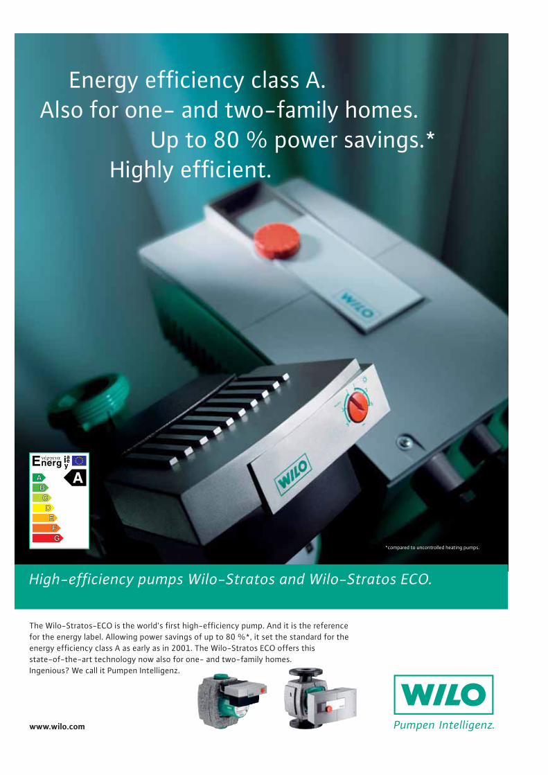
High-efficiency pumps Wilo-Stratos and Wilo-Stratos ECO.
Energy efficiency class A. Also for one- and two-family homes.
Up to 80 % power savings.*Highly efficient.
The Wilo-Stratos-ECO is the world's first high-efficiency pump. And it is the referencefor the energy label. Allowing power savings of up to 80 %*, it set the standard for theenergy efficiency class A as early as in 2001. The Wilo-Stratos ECO offers this state-of-the-art technology now also for one- and two-family homes.Ingenious? We call it Pumpen Intelligenz.
www.wilo.com
*compared to uncontrolled heating pumps.
3
Contents
Wilo Catalogue A1 - Circulating pumps in glandless design
Hea
tin
g, A
ir-c
on
dit
ion
ing
, C
oo
ling
Po
tab
le w
ater
cir
cula
tio
nSo
lar
ther
mal
Serv
ice/
Acc
esso
ries
, Sys
tem
sSw
itch
gear
s an
d C
ontr
ol D
evic
es
Pum
p M
anag
emen
t Sy
stem
s
General Notes and Abbreviations 4
Planning Guide 6
Heating, Air-conditioning, Cooling
Contents 36Wilo-Stratos ECO, Stratos, Stratos-DWilo-Star-E, TOP-E, TOP-EDWilo-SmartWilo-Star-RS, AXL, TOP-RLWilo-SE, TOP-S, TOP-DWilo-RP, PWilo-Star-RSD, SD, SE-TW, DOP
Potable water circulation
Contents 245Wilo-Stratos ECO-Z, Stratos-Z, Stratos-ZDWilo-Star-Z, TOP-Z, VeroLine-IP-Z
Solar thermal
Contents 303Wilo-Stratos ECO-STWilo-Star-ST
Service/AccessoriesSystems
Contents Service/Accessories 325Wilo-TOP Motor Technology, circuit diagramsSwitching plug, servicing apparatusThreaded pipe unions, adapter fittingsWilo thermal insulation shells, ClimaForm, Motor-Modules (MOT)
Contents Systems 343Wilo-Safe-WS, DrainLift Con
Switchgears and Control DevicesPump Management Systems Wilo-Control
Contents Switchgears and Control Devices 351Wilo-S1.../S2.../S4, SK, SR, SD, AS, VR-HVAC, CRn, CR
Contents Pump Management Systems Wilo-Control 421Wilo-IF-Moduls, IR-Monitor, Protect-Modul-CWilo-Control AnaCon/DigiCon/DigiCon-A
4 Subject to change without prior notice 09/2006 WILO AG
General Notes and Abbreviations
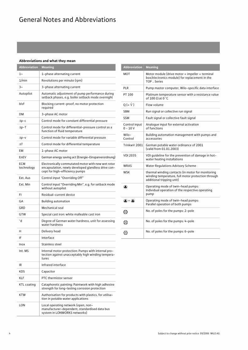
Abbreviations and what they mean
Abbreviation Meaning
1~ 1-phase alternating current
1/min Revolutions per minute (rpm)
3~ 3-phase alternating current
Autopilot Automatic adjustment of pump performance during setback phases, e.g. boiler setback mode overnight
blsf Blocking current-proof, no motor protection required
DM 3-phase AC motor
p-c Control mode for constant differential pressure
p-T Control mode for differential-pressure control as a function of fluid temperature
p-v Control mode for variable differential pressure
T Control mode for differential temperature
EM 1-phase AC motor
EnEV German energy saving act (Energie-Einsparverordnung)
ECM technology
Electronically commutated motor with new wet rotor encapsulation, newly developed glandless drive con-cept for high-efficiency pumps
Ext. Aus Control input “Overriding Off”
Ext. Min Control input “Overriding Min”, e.g. for setback mode without autopilot
FI Residual-current device
GA Building automation
GRD Mechanical seal
GTW Special cast iron: white malleable cast iron
°d Degree of German water hardness, unit for assessing water hardness
H Delivery head
IF Interface
Inox Stainless steel
Int. MS Internal motor protection: Pumps with internal pro-tection against unacceptably high winding tempera-tures
IR Infrared interface
KDS Capacitor
KLF PTC thermistor sensor
KTL coating Cataphoretic painting: Paintwork with high adhesive strength for long-lasting corrosion protection
KTW Authorisation for products with plastics, for utilisa-tion in potable water applications
LON Local operating network (open, non-manufacturer-dependent, standardised data bus system in LONWORKS networks)
Abbreviation Meaning
MOT Motor module (drive motor + impeller + terminal box/electronics module) for replacement in the TOP .. Series
PLR Pump master computer, Wilo-specific data interface
PT 100 Platinum temperature sensor with a resistance value of 100 at 0 °C
Q (= ) Flow volume
SBM Run signal or collective run signal
SSM Fault signal or collective fault signal
Control input0 - 10 V
Analogue input for external activation of functions
Wilo-Control
Building automation management with pumps and accessories
TrinkwV 2001 German potable water ordinance of 2001(valid from 01.01.2003)
VDI 2035 VDI guideline for the prevention of damage in hot-water heating installations
WRAS Water Regulations Advisory Scheme
WSK thermal winding contacts (in motor for monitoring winding temperature, full motor protection through additional tripping unit)
Operating mode of twin-head pumps:Individual operation of the respective operating pump
+ Operating mode of twin-head pumps:Parallel operation of both pumps
No. of poles for the pumps: 2-pole
No. of poles for the pumps: 4-pole
No. of poles for the pumps: 6-pole
V.
5
General Notes and Abbreviations
Wilo Catalogue A1 - Circulating pumps in glandless design
Hea
tin
g, A
ir-c
on
dit
ion
ing
, C
oo
ling
Po
tab
le w
ater
cir
cula
tio
nSo
lar
ther
mal
Serv
ice/
Acc
esso
ries
, Sys
tem
sSw
itch
gea
rs a
nd
Co
ntr
ol
Dev
ices
P
um
p M
anag
emen
t S y
stem
s
Wear and tearPumps or parts of pumps are subject to wear in accordance with
state-of-the-art technology (DIN 31051/DIN-EN 13306). This wear
may vary depending on operating parameters (temperature, pressure,
water conditions) and the installation/usage situation and may result
in the malfunction or failure at different times of the aforementioned
products/components, including their electrical/electronic circuitry.
Wearing parts are all components subject to rotary or dynamic strain,
including electronic components under tension, in particular:
- seals/gaskets (including rotating mechanical seals), seal ring
- bearings and shafts
- stuffing boxes
- capacitors
- relays/contactors/switches
- electronic circuits, semiconductor components, etc.
- impellers
- wearing rings/wearing plates
We do not accept liability for faults or defects arising from natural
wear and tear.
NoteAccording to the German energy saving act EnEV, starting from
1.2.2002, boilers with outputs in excess of 25 kW must be equipped
with either switchgear-equipped heating pumps for automatic per-
formance control or electronically controlled pumps.
In accordance with TrinkwV 2001 and DIN 50930-6 only circulating
pumps with corrosion-resistant pump housings in stainless steel or
red bronze (CC 491K) are to be used in potable water circulation
systems.
Pump replacementPlease refer to the current Wilo heating pumps replacement guide for
more detailed information on replacing heating pumps.
WILO – General Terms of Delivery and ServiceThe latest version of our General Terms of Delivery and Service can be
found on the Internet at
www.wilo.com
6 Subject to change without prior notice 09/2006 WILO AG
Planning GuideGlandless Pumps (General)
Pump selection: General NotesCirculating pumps should always be selected such that the specified
duty point is located on or as near as possible to the point of max.
efficiency (optimum capacity) of the max. speed H/Q pump curve.
Fig.: Pump curve
If the specified duty point is between two possible pump curves, it is
always good practice to choose the smaller pump.
Fig.: Pump selection
The resulting flow volume reduction has no appreciable effect on the
actual heating performance in heating systems. This applies to
pumps for chilled water applications.
Pump selection: Potable water circulation systemsPump selection
- In order to ensure correct configuration of the potable water circula-
tor, the pipeline system must be designed in accordance with both
DIN 1988 and the DVGW Worksheets W 551 to W 553.
- The necessary flow volume should be based on the figures recom-
mended in the standard and the DVGW guideline.
- If the hydraulic duty point lies between two pump curves, then the
next-largest circulator pr speed stage is to be selected in accordance
with DVGW Worksheet W 553.
- The thermal losses in the ascending and circulation pipelines for
potable water are to be reduced to a minimum through the installa-
tion of appropriate insulation.
Because most potable water circulation systems permit periodic
stops of the circulating pump (generally at night), a time switch for
automatic On/Off control should always be part of standard equip-
ment.
The German EnEV requires periodic pump shutdown.
Legionellae blocking circuits in the heat generator and/or in the heat-
ing control unit are to be observed and taken into account during
programming.
Maximum potable water temperatureIn view of the hardness-forming particles contained in water, potable
water circulation systems should not be operated at temperatures in
excess of 65 °C.
This limit is required to avoid the formation of lime deposits.
Circulation pipeA gravity brake should always be installed in order to exclude the
possibility of incorrect circulation and for the prevention of gravity
circulation when the pump is switched off.
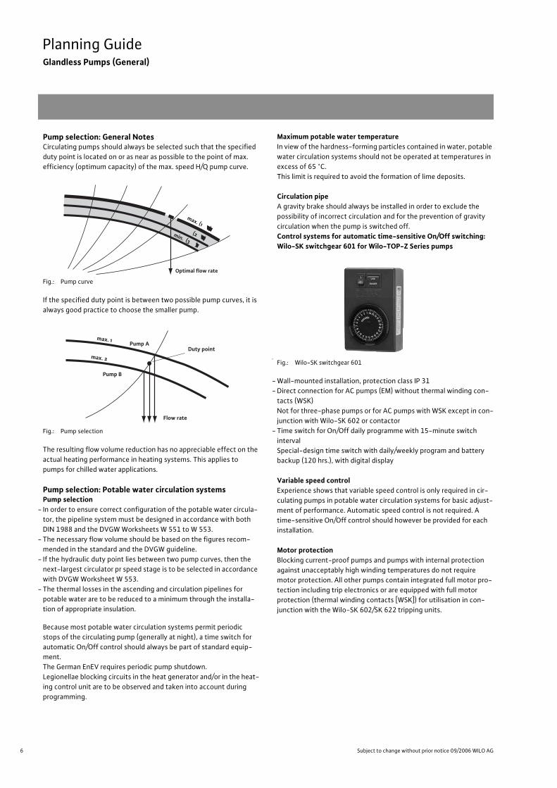
Control systems for automatic time-sensitive On/Off switching:Wilo-SK switchgear 601 for Wilo-TOP-Z Series pumps
ll
Fig.: Wilo-SK switchgear 601
- Wall-mounted installation, protection class IP 31
- Direct connection for AC pumps (EM) without thermal winding con-
tacts (WSK)
Not for three-phase pumps or for AC pumps with WSK except in con-
junction with Wilo-SK 602 or contactor
- Time switch for On/Off daily programme with 15-minute switch
interval
Special-design time switch with daily/weekly program and battery
backup (120 hrs.), with digital display
Variable speed controlExperience shows that variable speed control is only required in cir-
culating pumps in potable water circulation systems for basic adjust-
ment of performance. Automatic speed control is not required. A
time-sensitive On/Off control should however be provided for each
installation.
Motor protectionBlocking current-proof pumps and pumps with internal protection
against unacceptably high winding temperatures do not require
motor protection. All other pumps contain integrated full motor pro-
tection including trip electronics or are equipped with full motor
protection (thermal winding contacts [WSK]) for utilisation in con-
junction with the Wilo-SK 602/SK 622 tripping units.
max. (1 )min. (3 )
(2 )
Optimal flow rate
max. 1
max. 2
Pump ADuty point
Flow rate
Pump B
7
Planning GuideGlandless Pumps (General)
Wilo Catalogue A1 - Circulating pumps in glandless design
Hea
tin
g, A
ir-c
on
dit
ion
ing
, C
oo
ling
Po
tab
le w
ater
cir
cula
tio
nSo
lar
ther
mal
Serv
ice/
Acc
esso
ries
, Sys
tem
sSw
itch
gea
rs a
nd
Co
ntr
ol
Dev
ices
P
um
p M
anag
emen
t S y
stem
s
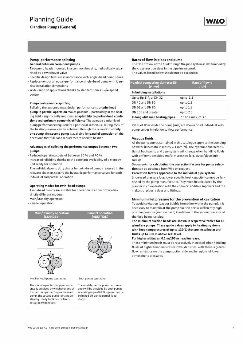
Pump-performance splittingGeneral notes on twin-head pumps
- Two pump heads mounted in a common housing, hydraulically sepa-
rated by a switchover valve
- Specific design features in accordance with single-head pump series
- Replacement of an equal-performance single-head pump with iden-
tical installation dimensions
- Wide range of applications thanks to standard series 3-/4-speed
control
Pump-performance splittingSplitting the assigned max. design performance to a twin-head pump in parallel operation makes possible - particularly in the heat-
ing field - significantly improved adaptability to partial-load condi-tions and optimum economic efficiency.The average partial-load
pump performance required for a particular season, i.e. during 85% of
the heating season, can be achieved through the operation of only one pump; the second pump is available for parallel operation on the
occasions that full-load requirements need to be met.
Advantages of splitting the performance output between two pumps:
- Reduced operating costs of between 50 % and 70 %
- Increased reliability thanks to the constant availability of a standby
unit ready for operation
The individual pump duty charts for twin-head pumps featured in the
relevant chapters specify the hydraulic performance values for both
individual and parallel operation.
Operating modes for twin-head pumpsTwin-head pumps are suitable for operation in either of two dis-
tinctly different modes:
- Main/Standby operation
- Parallel operation
Rates of flow in pipes and pumpThe rate of flow of the fluid through the pipe system is determined by
the cross-section sizes in the pipeline network.
The values listed below should not be exceeded:
Rates of flow inside the pump [m/s] are shown on all individual Wilo
pump curves in relation to flow performance.
Viscous fluidsAll the pump curves contained in this catalogue apply to the pumping
of water (kinematic viscosity = 1 mm2/s). The hydraulic characteris-
tics of both pump and pipe system will change when handling fluids
with different densities and/or viscosities (e.g. water/glycol mix-
tures)!
Documents for calculating the correction factors for pump selec-tion can be obtained from Wilo on request.
Correction factors applicable to the individual pipe system(increased pressure loss, lower specific heat capacity) cannot be fur-
nished by the pump manufacturer.They must be calculated by the
planner in co-operation with the chemical additive suppliers and the
makers of pipes, valves and fittings.
Minimum inlet pressure for the prevention of cavitationTo avoid cavitation (vapour bubble formation within the pump), it is
necessary to maintain at the pump suction port a sufficiently high
positive pressure (suction head) in relation to the vapour pressure of
the fluid being handled.
The minimum suction heads are shown in respective tables for all glandless pumps. These guide values apply to heating systems with feed temperatures of up to 130°C that are installed at alti-tudes up to 300 m above seal level.For higher altitudes: 0.1 m/100 m head increase.These minimum heads must be respectively increased when handling
fluids of higher temperatures or lower densities, with there is greater
flow resistance on the pump suction side and in regions of lower
atmospheric pressures.
Main/Standby operation(STANDBY)
Parallel operation(ADDITION)
No. I or No. II pump operating Both pumps operating
The model-specific pump perform-ance is provided by whichever one of the two pumps is acting as the main pump; the second pump remains on standby, ready for time- or fault-actuated switchovers.
The model-specific pump perform-ance will be provided by both pumps operating in parallel. One pump can be switched off during partial-load states.
Nominal connection diameter DN[ø mm]
Rate of flow v[m/s]
In building installations
Up to Rp 11/4 or DN 32 up to 1.2
DN 40 and DN 50 up to 1.5
DN 65 and DN 80 up to 1.8
DN 100 and greater up to 2.0
In long-distance heating pipes 2.5 to a max. of 3.5
8 Subject to change without prior notice 09/2006 WILO AG
Planning GuideGlandless Pumps (General)
Notes on installation and operationPermissible ambient temperature: 0 °C to +40 °C
InstallationGlandless pumps must be installed in dry, well-ventilated, frost-free
spaces. They are not suitable for outdoor installation.
CondensationAll standard series pumps for cold-water operation that are intended
for standard usage down to -10 °C/-20 °C are fully condensation-
proof.
The grey cast iron pump housing that comes with the following
series:
- Stratos/Stratos-D
- TOP-E/-ED
- TOP-S/-SD
- TOP-D
- TOP-RL
- P/RP (not RP 25/60-2)
- DOP
- AXL/SE/SE-TW
is provided with a special coating for surface finishing
(KTL: cataphoretic painting).
The benefits provided by this coating are:
- optimum corrosion protection against condensation formation on
the pump housings in cold-water installations
- very high scratch and impact resistance
To avoid condensation forming on Wilo-Top-E/-ED pumps, it is
essential to ensure that the fluid temperature is equal to or greater
than the ambient temperature at all times.
Intermittent operationThe series
- Stratos/Stratos-D
- Star-RS/RSD
- TOP-S/-SD
- TOP-D
- TOP-Z
- TOP-RL
- AXL/SE/SE-TW
can also be utilised for intermittent operation.
Operating pressureThe max. system pressure (operating pressure) and the flange ver-
sions for the pumps are listed in the relevant tables. All flanges on
glandless pumps (except Stratos, Stratos-Z, Stratos-D and
Stratos-ZD) have pressure-measurement connections R 18.
ConnectionsScrew-end pumpsScrew-end pumps are equipped with connecting threads in accord-
ance with DIN EN ISO 228 Part 1. Seals are included in the scope of
delivery. Threaded pipe unions with threads in accordance with
DIN 2999 must be ordered separately.
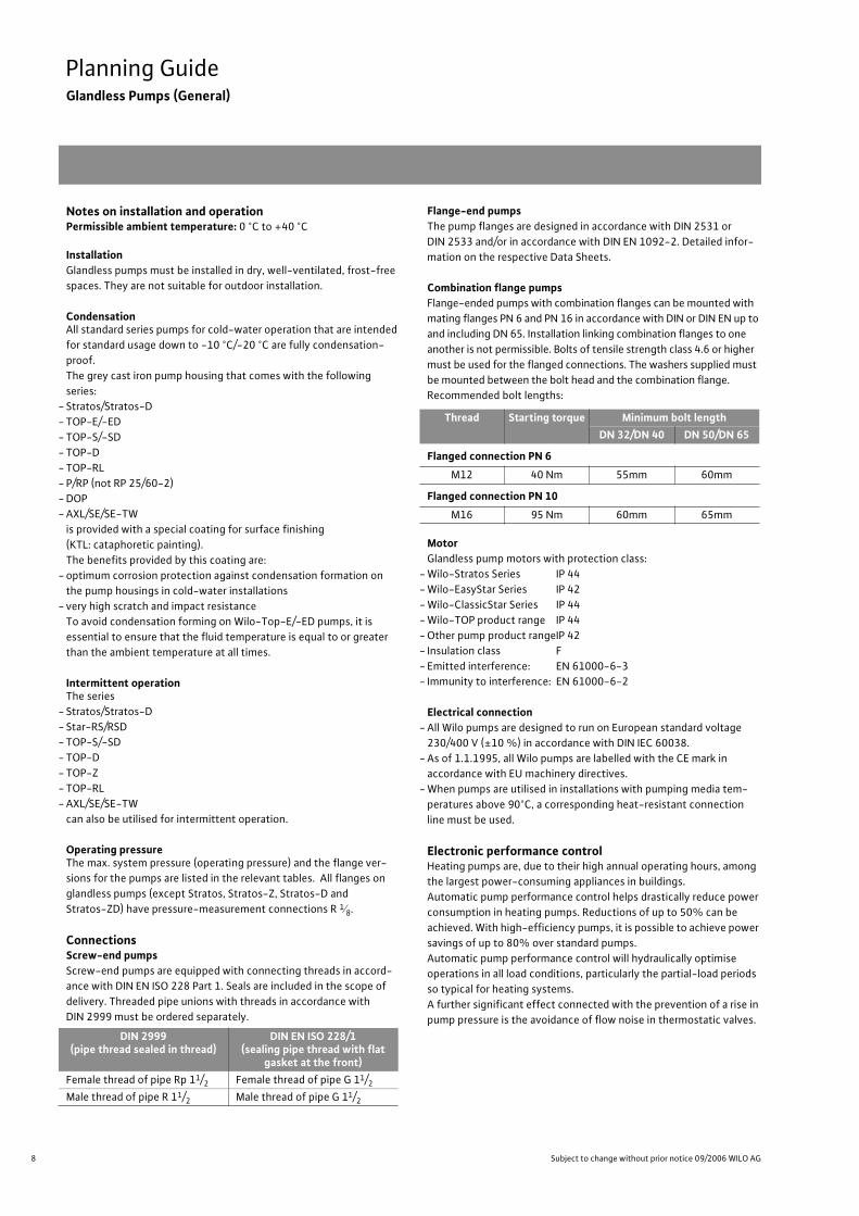
Flange-end pumpsThe pump flanges are designed in accordance with DIN 2531 or
DIN 2533 and/or in accordance with DIN EN 1092-2. Detailed infor-
mation on the respective Data Sheets.
Combination flange pumpsFlange-ended pumps with combination flanges can be mounted with
mating flanges PN 6 and PN 16 in accordance with DIN or DIN EN up to
and including DN 65. Installation linking combination flanges to one
another is not permissible. Bolts of tensile strength class 4.6 or higher
must be used for the flanged connections. The washers supplied must
be mounted between the bolt head and the combination flange.
Recommended bolt lengths:
MotorGlandless pump motors with protection class:
- Wilo-Stratos Series IP 44
- Wilo-EasyStar Series IP 42
- Wilo-ClassicStar Series IP 44
- Wilo-TOP product range IP 44
- Other pump product rangeIP 42
- Insulation class F
- Emitted interference: EN 61000-6-3
- Immunity to interference: EN 61000-6-2
Electrical connection- All Wilo pumps are designed to run on European standard voltage
230/400 V (±10 %) in accordance with DIN IEC 60038.
- As of 1.1.1995, all Wilo pumps are labelled with the CE mark in
accordance with EU machinery directives.
- When pumps are utilised in installations with pumping media tem-
peratures above 90°C, a corresponding heat-resistant connection
line must be used.
Electronic performance controlHeating pumps are, due to their high annual operating hours, among
the largest power-consuming appliances in buildings.
Automatic pump performance control helps drastically reduce power
consumption in heating pumps. Reductions of up to 50% can be
achieved. With high-efficiency pumps, it is possible to achieve power
savings of up to 80% over standard pumps.
Automatic pump performance control will hydraulically optimise
operations in all load conditions, particularly the partial-load periods
so typical for heating systems.
A further significant effect connected with the prevention of a rise in
pump pressure is the avoidance of flow noise in thermostatic valves.
DIN 2999(pipe thread sealed in thread)
DIN EN ISO 228/1(sealing pipe thread with flat
gasket at the front)
Female thread of pipe Rp 11/2 Female thread of pipe G 11/2
Male thread of pipe R 11/2 Male thread of pipe G 11/2
Thread Starting torque Minimum bolt length
DN 32/DN 40 DN 50/DN 65
Flanged connection PN 6
M12 40 Nm 55mm 60mm
Flanged connection PN 10
M16 95 Nm 60mm 65mm
9
Planning GuideGlandless Pumps (General)
Wilo Catalogue A1 - Circulating pumps in glandless design
Hea
tin
g, A
ir-c
on
dit
ion
ing
, C
oo
ling
Po
tab
le w
ater
cir
cula
tio
nSo
lar
ther
mal
Serv
ice/
Acc
esso
ries
, Sys
tem
sSw
itch
gea
rs a
nd
Co
ntr
ol
Dev
ices
P
um
p M
anag
emen
t S y
stem
s
German energy-saving ordinance EnEVWithin the framework of statutory measures for CO2 reduction in
connection with the power consumption of heating circulating
pumps, the German legislature has established in the EnEV that cir-
culating pumps fitted after 01 Feb. 2002 with nominal thermal out-
put ratings starting at 25 kW must be configured in such a way that
electrical power consumption is automatically adjusted in at least
three stages to the delivery demands required by operation.
Although EnEV prescribes the application of automatic pump per-
formance controls starting with a nominal thermal output of 25 kW,
by far the greater savings potential for power and CO2 can be found
in single- and two-family houses, i.e. in systems that fall below the
25 kW minimum.
Pump performance control does not replace the need for correct
dimensioning of the circulating pump! The pump performance
installed must also be checked when the pump is replaced. Controlled
pumps that are slightly overdimensioned do not pose any risk if they
are correctly set to the nominal load requirement.
Standards/guidelines- CE mark (all Wilo pumps)
- Certification in accordance with:
- ISO 9001,
- ISO 14001,
- VDA 6.1
Pump curvesThe pump curves apply to water at + 20°C and with a kinematic vis-
cosity of 1 mm2/s.
The pump curves take into account the standard European voltages
of 230/400 V.
Pump controlWhen operating Wilo pumps with control units or module accesso-
ries, it is essential to adhere to the electrical operating conditions as
set out in VDE 0160.
When operating glandless and glanded pumps in conjunction with
frequency-converter models not supplied by Wilo, it is necessary to
use output filters to reduce motor noise and prevent harmful voltage
peaks and to adhere to the following limit values:
- Glandless pumps with P2 1.3 kW and glanded pumps with
P2 1.1 kW
Rate of voltage rise du/dt < 500 V/µs
Voltage peaks û < 650 V
For noise reduction on glandless pump motors, it is recommended
that sine filters (LC filters) be used rather than du/dt filters
(RC filters).
- Glanded pumps with P2 > 1.1 kW
Rate of voltage rise du/dt < 500 V/µs
Voltage peaks û < 850 V
Installations with large cable lengths (l > 10 m) between converter
and motor may cause increases of the du/dt and û levels (resonance).
The same may happen for operation with more than 4 motor units at
one voltage source.
The output filters must be selected as recommended by the con-
verter manufacturer or filter supplier, respectively.
The pumps must be operated at a max. of 95 % of their rated motor
speed if the frequency converter causes motor losses.
The following limit values at the pump connection terminals must not
be undershot if TOP-S/-SD, TOP-D and TOP-Z Series glandless
pumps are operated in conjunction with a frequency converter:
Umin = 150 V
fmin = 30 Hz
Minimum flow volumeLarger pumps require a minimum flow volume to ensure trouble-free
operation. Operation against closed gate valves, flow volume Q = 0,
can lead to overheating inside the dry well and damage to the shaft
seal.
- Constraints on pump operation when Q = 0:
Permitted operating temperature 10 K less than Tmax
- to P2 = 1 kW unproblematic
- starting with P2 > 1 kW continuous operation, a minimum flow
volume of
Q = 10 % QNom is required
Further information in special cases on request.
Motor protectionService life and operational reliability of a circulating pump depend to
a great extent on the choice of the correct motor protection device.
Motor protection switches are unsuitable for utilisation in conjunc-
tion with multi-speed pumps due to their different nominal current
ratings at different speed settings which require correspondingly dif-
ferent fuse protection.
All circulating pumps are either
- blocking current-proof
- provided with internal protection against unacceptably high winding
temperatures
- provided with full motor protection in the form of thermal winding
contacts (WSK) and a separate Wilo tripping unit (e.g. Wilo-SK 602/
SK 622)
- equipped with full motor protection and a fully integrated trip
mechanism (Wilo-Stratos Series, Wilo-TOP Series, except TOP-D,
see pump data).
No further motor protection by the customer is required except
where this is stipulated for blocking current-proof motors and
motors with internal protection against unacceptably high winding
temperatures by the energy supply company.
10 Subject to change without prior notice 09/2006 WILO AG
Planning GuideGlandless Pumps (General)
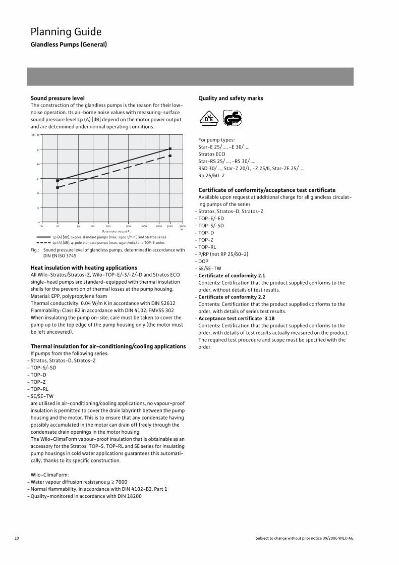
Sound pressure levelThe construction of the glandless pumps is the reason for their low-
noise operation. Its air-borne noise values with measuring-surface
sound pressure level Lp (A) [dB] depend on the motor power output
and are determined under normal operating conditions.
Fig.: Sound pressure level of glandless pumps, determined in accordance with DIN EN ISO 3745
Heat insulation with heating applicationsAll Wilo-Stratos/Stratos-Z, Wilo-TOP-E/-S/-Z/-D and Stratos ECO
single-head pumps are standard-equipped with thermal insulation
shells for the prevention of thermal losses at the pump housing.
Material: EPP, polypropylene foam
Thermal conductivity: 0.04 W/m K in accordance with DIN 52612
Flammability: Class B2 in accordance with DIN 4102; FMVSS 302
When insulating the pump on-site, care must be taken to cover the
pump up to the top edge of the pump housing only (the motor must
be left uncovered).
Thermal insulation for air-conditioning/cooling applicationsIf pumps from the following series:
- Stratos, Stratos-D, Stratos-Z
- TOP-S/-SD
- TOP-D
- TOP-Z
- TOP-RL
- SE/SE-TW
are utilised in air-conditioning/cooling applications, no vapour-proof
insulation is permitted to cover the drain labyrinth between the pump
housing and the motor. This is to ensure that any condensate having
possibly accumulated in the motor can drain off freely through the
condensate drain openings in the motor housing.
The Wilo-ClimaForm vapour-proof insulation that is obtainable as an
accessory for the Stratos, TOP-S, TOP-RL and SE series for insulating
pump housings in cold water applications guarantees this automati-
cally, thanks to its specific construction.
Wilo-ClimaForm:
- Water vapour diffusion resistance µ 7000
- Normal flammability, in accordance with DIN 4102-B2, Part 1
- Quality-monitored in accordance with DIN 18200
Quality and safety marks
For pump types:
Star-E 25/ ..., -E 30/ ...,
Stratos ECO
Star-RS 25/ ..., -RS 30/ ...,
RSD 30/ ..., Star-Z 20/1, -Z 25/6, Star-ZE 25/ ...,
Rp 25/60-2
Certificate of conformity/acceptance test certificateAvailable upon request at additional charge for all glandless circulat-
ing pumps of the series
- Stratos, Stratos-D, Stratos-Z
- TOP-E/-ED
- TOP-S/-SD
- TOP-D
- TOP-Z
- TOP-RL
- P/RP (not RP 25/60-2)
- DOP
- SE/SE-TW
- Certificate of conformity 2.1Contents: Certification that the product supplied conforms to the
order, without details of test results.
- Certificate of conformity 2.2Contents: Certification that the product supplied conforms to the
order, with details of series test results.
- Acceptance test certificate 3.1BContents: Certification that the product supplied conforms to the
order, with details of test results actually measured on the product.
The required test procedure and scope must be specified with the
order.
60
50
40
20
30
10
010 20 50 100 200 500 1000 2000 5000
WRate motor output P2
Lp (A) [dB], 2-pole standard pumps (max. 2900 1/min.) and Stratos seriesLp (A) [dB], 4-pole standard pumps (max. 1450 1/min.) and TOP-E series
3000
[dB]
11
Planning GuideGlandless Pumps (General)
Wilo Catalogue A1 - Circulating pumps in glandless design
Hea
tin
g, A
ir-c
on
dit
ion
ing
, C
oo
ling
Po
tab
le w
ater
cir
cula
tio
nSo
lar
ther
mal
Serv
ice/
Acc
esso
ries
, Sys
tem
sSw
itch
gea
rs a
nd
Co
ntr
ol
Dev
ices
P
um
p M
anag
emen
t S y
stem
s
1) For installation positions for Wilo-Stratos/-Stratos-Z/-Stratos-D/-Stratos-ZD, refer to “Planning Guide High-Efficiency Pumps“
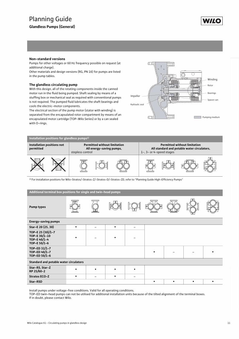
Non-standard versionsPumps for other voltages or 60 Hz frequency possible on request (at
additional charge).
Other materials and design versions (RG, PN 16) for pumps are listed
in the pump tables.
The glandless circulating pumpWith this design, all of the rotating components inside the canned
motor run in the fluid being pumped. Shaft sealing by means of a
stuffing box or mechanical seal as required with conventional pumps
is not required. The pumped fluid lubricates the shaft bearings and
cools the electric-motor components.
The electrical section of the pump motor (stator with winding) is
separated from the encapsulated rotor compartment by means of an
encapsulated motor cartridge (TOP-Wilo Series) or by a can sealed
with O-rings.
Installation positions for glandless pumps1)
Installation positions not permitted
Permitted without limitationAll energy-saving pumps,
stepless control
Permitted without limitationAll standard and potable water circulators,
1-, 3- or 4-speed stages
Additional terminal box positions for single and twin-head pumps
Pump types
Energy-saving pumps
Star-E 20 (25, 30) • – • –
TOP-E 25 (30)/1-7TOP-E 30/1-10TOP-E 40/1-4TOP-E 50/1-6
• – • –
TOP-ED 32/1-7TOP-ED 40/1-7TOP-ED 50/1-6
• – – •
Standard and potable water circulators
Star-RS, Star-ZRP 25/60-2
• • • •
Stratos ECO-Z • – • –
Star-RSD • • • •
Install pumps under voltage-free conditions. Valid for all operating conditions.TOP-ED twin-head pumps can not be utilised for additional installation units because of the tilted alignment of the terminal boxes.If in doubt, please contact Wilo.
Impeller
Winding
Rotor
Bearings
Spacer can
Pumping medium
Hydraulic seal
12 Subject to change without prior notice 09/2006 WILO AG
Planning GuideConnection Notes Wilo-TOP and Wilo-Stratos
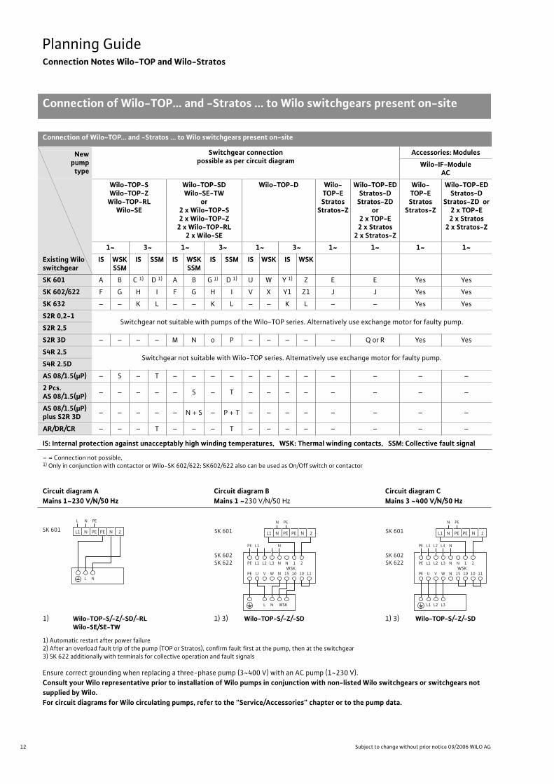
Connection of Wilo-TOP... and -Stratos ... to Wilo switchgears present on-site
Connection of Wilo-TOP... and -Stratos ... to Wilo switchgears present on-site
Newpump
type
Switchgear connectionpossible as per circuit diagram
Accessories: Modules
Wilo-IF-ModuleAC
Existing Wilo switchgear
Wilo-TOP-SWilo-TOP-Z
Wilo-TOP-RLWilo-SE
Wilo-TOP-SDWilo-SE-TW
or2 x Wilo-TOP-S2 x Wilo-TOP-Z
2 x Wilo-TOP-RL2 x Wilo-SE
Wilo-TOP-D Wilo-TOP-EStratos
Stratos-Z
Wilo-TOP-EDStratos-D
Stratos-ZDor
2 x TOP-E2 x Stratos
2 x Stratos-Z
Wilo-TOP-EStratos
Stratos-Z
Wilo-TOP-EDStratos-D
Stratos-ZD or2 x TOP-E2 x Stratos
2 x Stratos-Z
1~ 3~ 1~ 3~ 1~ 3~ 1~ 1~ 1~ 1~
IS WSKSSM
IS SSM IS WSKSSM
IS SSM IS WSK IS WSK
SK 601 A B C 1) D 1) A B G 1) D 1) U W Y 1) Z E E Yes Yes
SK 602/622 F G H I F G H I V X Y1 Z1 J J Yes Yes
SK 632 – – K L – – K L – – K L – – Yes Yes
S2R 0,2-1Switchgear not suitable with pumps of the Wilo-TOP series. Alternatively use exchange motor for faulty pump.
S2R 2,5
S2R 3D – – – – M N o P – – – – – Q or R Yes Yes
S4R 2,5Switchgear not suitable with Wilo-TOP series. Alternatively use exchange motor for faulty pump.
S4R 2.5D
AS 08/1.5(µP) – S – T – – – – – – – – – – – –
2 Pcs.AS 08/1.5(µP)
– – – – – S – T – – – – – – – –
AS 08/1.5(µP)plus S2R 3D
– – – – – N + S – P + T – – – – – – – –
AR/DR/CR – – – T – – – T – – – – – – – –
IS: Internal protection against unacceptably high winding temperatures, WSK: Thermal winding contacts, SSM: Collective fault signal
– = Connection not possible, 1) Only in conjunction with contactor or Wilo-SK 602/622; SK602/622 also can be used as On/Off switch or contactor
Circuit diagram A Mains 1~230 V/N/50 Hz
Circuit diagram BMains 1 ~230 V/N/50 Hz
Circuit diagram CMains 3 ~400 V/N/50 Hz
1) Wilo-TOP-S/-Z/-SD/-RLWilo-SE/SE-TW
1) 3) Wilo-TOP-S/-Z/-SD 1) 3) Wilo-TOP-S/-Z/-SD
1) Automatic restart after power failure2) After an overload fault trip of the pump (TOP or Stratos), confirm fault first at the pump, then at the switchgear3) SK 622 additionally with terminals for collective operation and fault signals
Ensure correct grounding when replacing a three-phase pump (3~400 V) with an AC pump (1~230 V).
Consult your Wilo representative prior to installation of Wilo pumps in conjunction with non-listed Wilo switchgears or switchgears not supplied by Wilo.For circuit diagrams for Wilo circulating pumps, refer to the “Service/Accessories” chapter or to the pump data.
N
SK 601
NL PE
PE PEL1 N N 2
L
PE
PE
L1
U
L2
V
L3
W
N
PE L1 N
N
N
15
L N WSK
1
10
2
10 11WSK
SK 602SK 622
SK 601
N PE
PE PEL1 N N 2
PE
PE
L1
U
L2
V
L3
W
N
PE L1 L2 L3 N
N
N
15
L2L1 L3
1
10
2
10 11WSK
SK 602SK 622
SK 601
N PE
PE PEL1 N N 2
13
Planning GuideConnection Notes Wilo-TOP and Wilo-Stratos
Connection of Wilo-TOP... and -Stratos ... to Wilo switchgears present on-site
Wilo Catalogue A1 - Circulating pumps in glandless design
Hea
tin
g, A
ir-c
on
dit
ion
ing
, C
oo
ling
Po
tab
le w
ater
cir
cula
tio
nSo
lar
ther
mal
Serv
ice/
Acc
esso
ries
, Sys
tem
sSw
itch
gea
rs a
nd
Co
ntr
ol
Dev
ices
P
um
p M
anag
emen
t S y
stem
s
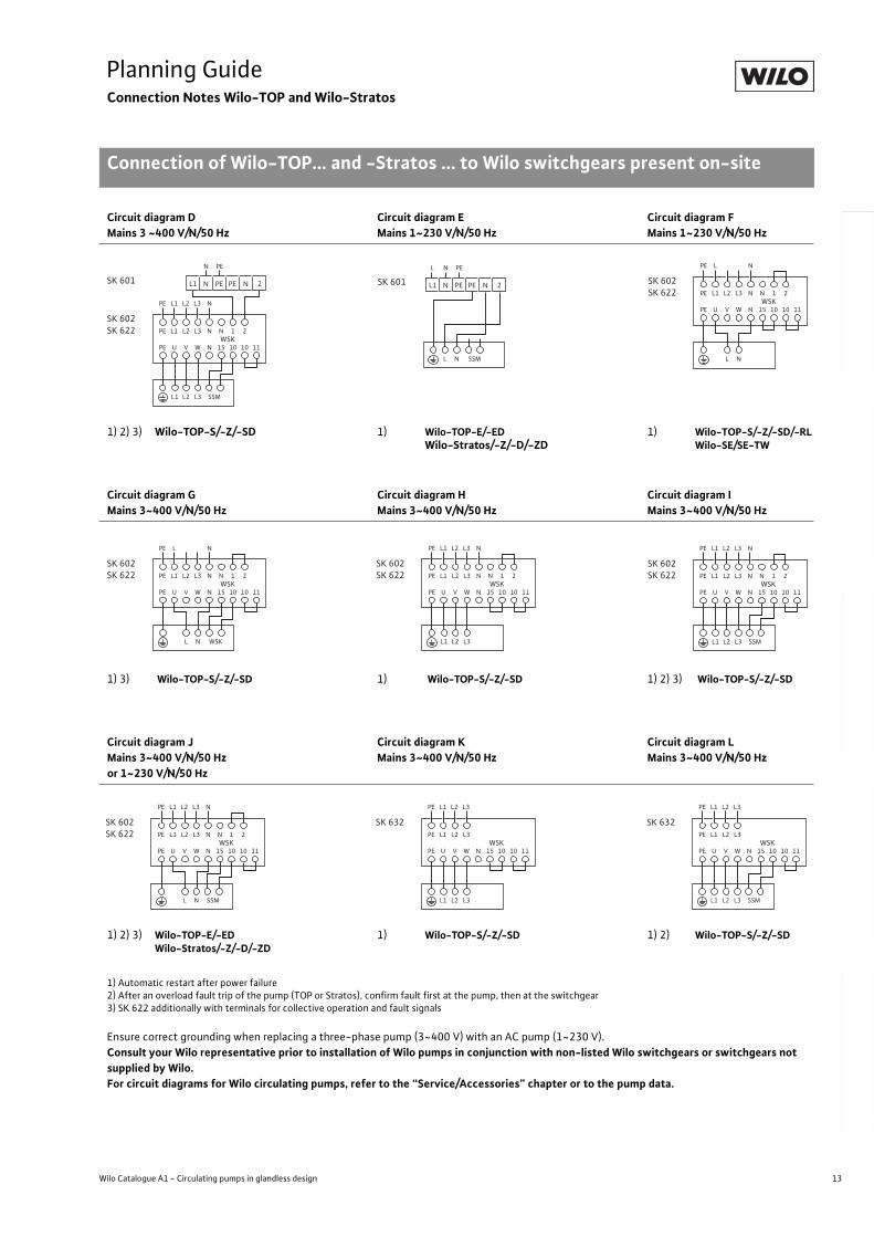
Circuit diagram DMains 3 ~400 V/N/50 Hz
Circuit diagram EMains 1~230 V/N/50 Hz
Circuit diagram FMains 1~230 V/N/50 Hz
1) 2) 3) Wilo-TOP-S/-Z/-SD 1) Wilo-TOP-E/-EDWilo-Stratos/-Z/-D/-ZD
1) Wilo-TOP-S/-Z/-SD/-RLWilo-SE/SE-TW
Circuit diagram GMains 3~400 V/N/50 Hz
Circuit diagram HMains 3~400 V/N/50 Hz
Circuit diagram IMains 3~400 V/N/50 Hz
1) 3) Wilo-TOP-S/-Z/-SD 1) Wilo-TOP-S/-Z/-SD 1) 2) 3) Wilo-TOP-S/-Z/-SD
Circuit diagram JMains 3~400 V/N/50 Hz or 1~230 V/N/50 Hz
Circuit diagram KMains 3~400 V/N/50 Hz
Circuit diagram LMains 3~400 V/N/50 Hz
1) 2) 3) Wilo-TOP-E/-EDWilo-Stratos/-Z/-D/-ZD
1) Wilo-TOP-S/-Z/-SD 1) 2) Wilo-TOP-S/-Z/-SD
1) Automatic restart after power failure2) After an overload fault trip of the pump (TOP or Stratos), confirm fault first at the pump, then at the switchgear3) SK 622 additionally with terminals for collective operation and fault signals
Ensure correct grounding when replacing a three-phase pump (3~400 V) with an AC pump (1~230 V).
Consult your Wilo representative prior to installation of Wilo pumps in conjunction with non-listed Wilo switchgears or switchgears not supplied by Wilo.For circuit diagrams for Wilo circulating pumps, refer to the “Service/Accessories” chapter or to the pump data.
PE
PE
L1
U
L2
V
L3
W
N
PE L1 L2 L3 N
N
N
15
L2L1 L3 SSM
1
10
2
10 11WSK
SK 602SK 622
SK 601
N PE
PE PEL1 N N 2
N
SK 601
NL PE
PE PEL1 N N 2
L SSM
PE
PE
L1
U
L2
V
L3
W
N
PE L N
N
N
15
L N
1
10
2
10 11WSK
SK 602SK 622
PE
PE
L1
U
L2
V
L3
W
N
PE L N
N
N
15
1
10
2
10 11WSK
SK 602SK 622
L N WSK
PE
PE
L1
U
L2
V
L3
W
N
PE L1 L2 L3 N
N
N
15
L2L1 L3
1
10
2
10 11WSK
SK 602SK 622 PE
PE
L1
U
L2
V
L3
W
N
PE L1 L2 L3 N
N
N
15
L2L1 L3 SSM
1
10
2
10 11WSK
SK 602SK 622
PE
PE
L1
U
L2
V
L3
W
N
PE L1 L2 L3 N
N
N
15
L N SSM
1
10
2
10 11WSK
SK 602SK 622 PE
PE
L1
U
L2
V
L3
W
PE L1 L2 L3
N 15
L2 L3L1
10 10 11WSK
SK 632PE
PE
L1
U
L2
V
L3
W
PE L1 L2 L3
N 15
L2 L3L1
10 10 11WSK
SK 632
SSM
14 Subject to change without prior notice 09/2006 WILO AG
Planning GuideConnection Notes Wilo-TOP and Wilo-Stratos
Connection of Wilo-TOP... and -Stratos ... to Wilo switchgears present on-site
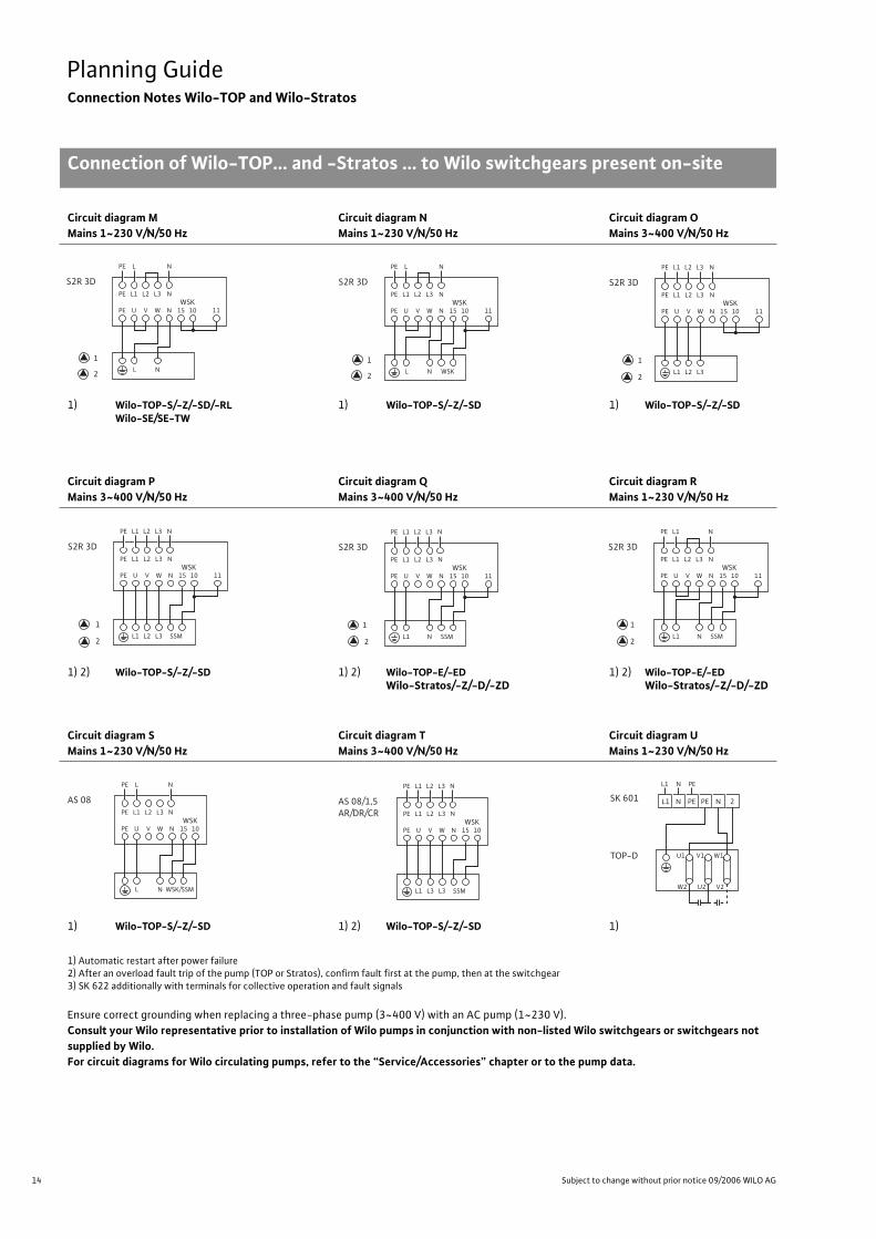
Circuit diagram MMains 1~230 V/N/50 Hz
Circuit diagram NMains 1~230 V/N/50 Hz
Circuit diagram OMains 3~400 V/N/50 Hz
1) Wilo-TOP-S/-Z/-SD/-RLWilo-SE/SE-TW
1) Wilo-TOP-S/-Z/-SD 1) Wilo-TOP-S/-Z/-SD
Circuit diagram PMains 3~400 V/N/50 Hz
Circuit diagram QMains 3~400 V/N/50 Hz
Circuit diagram RMains 1~230 V/N/50 Hz
1) 2) Wilo-TOP-S/-Z/-SD 1) 2) Wilo-TOP-E/-EDWilo-Stratos/-Z/-D/-ZD
1) 2) Wilo-TOP-E/-EDWilo-Stratos/-Z/-D/-ZD
Circuit diagram S Mains 1~230 V/N/50 Hz
Circuit diagram T Mains 3~400 V/N/50 Hz
Circuit diagram U Mains 1~230 V/N/50 Hz
1) Wilo-TOP-S/-Z/-SD 1) 2) Wilo-TOP-S/-Z/-SD 1)
1) Automatic restart after power failure2) After an overload fault trip of the pump (TOP or Stratos), confirm fault first at the pump, then at the switchgear3) SK 622 additionally with terminals for collective operation and fault signals
Ensure correct grounding when replacing a three-phase pump (3~400 V) with an AC pump (1~230 V).
Consult your Wilo representative prior to installation of Wilo pumps in conjunction with non-listed Wilo switchgears or switchgears not supplied by Wilo.For circuit diagrams for Wilo circulating pumps, refer to the “Service/Accessories” chapter or to the pump data.
PE
PE
L1
U
L2
V
L3
W
N
PE L N
N 15
L N
10 11 WSK
S2R 3D
1
2
PE
PE
L1
U
L2
V
L3
W
N
PE L N
N 15
L N WSK
10 11WSK
S2R 3D
1
2
PE
PE
L1
U
L2
V
L3
W
PE L1 L2 L3
N 15
L2 L3L1
10 11WSK
S2R 3D
1
2
N
N
PE
PE
L1
U
L2
V
L3
W
PE L1 L2 L3
N 15
L2 L3L1 SSM
10 11WSK
S2R 3D
1
2
N
N
PE
PE
L1
U
L2
V
L3
W
PE L1 L2 L3
N 15
NL1 SSM
10 11WSK
S2R 3D
1
2
N
N
PE
PE
L1
U
L2
V
L3
W
PE L1
N 15
NL1 SSM
10 11WSK
S2R 3D
1
2
N
N
PE
PE
L1
U
L2
V
L3
W
PE L
N 15 10 WSK
AS 08N
N
N L WSK/SSM
PE
PE
L1
U
L2
V
L3
W
PE L1 L2 L3
N 15
L3L1 L3 SSM
10WSK
AS 08/1,5AR/DR/CR N
N
SK 601
TOP-D
NL1 PE
PE PEL1 N N 2
U1 V1 W1
W2 U2 V2
15
Planning GuideConnection Notes Wilo-TOP and Wilo-Stratos
Connection of Wilo-TOP... and -Stratos ... to Wilo switchgears present on-site
Wilo Catalogue A1 - Circulating pumps in glandless design
Hea
tin
g, A
ir-c
on
dit
ion
ing
, C
oo
ling
Po
tab
le w
ater
cir
cula
tio
nSo
lar
ther
mal
Serv
ice/
Acc
esso
ries
, Sys
tem
sSw
itch
gea
rs a
nd
Co
ntr
ol
Dev
ices
P
um
p M
anag
emen
t S y
stem
s
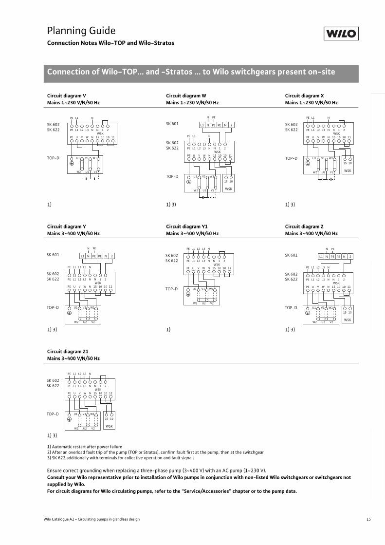
1) Automatic restart after power failure2) After an overload fault trip of the pump (TOP or Stratos), confirm fault first at the pump, then at the switchgear3) SK 622 additionally with terminals for collective operation and fault signals
Ensure correct grounding when replacing a three-phase pump (3~400 V) with an AC pump (1~230 V).
Consult your Wilo representative prior to installation of Wilo pumps in conjunction with non-listed Wilo switchgears or switchgears not supplied by Wilo.For circuit diagrams for Wilo circulating pumps, refer to the “Service/Accessories” chapter or to the pump data.
Circuit diagram V Mains 1~230 V/N/50 Hz
Circuit diagram W Mains 1~230 V/N/50 Hz
Circuit diagram X Mains 1~230 V/N/50 Hz
1) 1) 3) 1) 3)
Circuit diagram Y Mains 3~400 V/N/50 Hz
Circuit diagram Y1Mains 3~400 V/N/50 Hz
Circuit diagram Z Mains 3~400 V/N/50 Hz
1) 3) 1) 1) 3)
Circuit diagram Z1Mains 3~400 V/N/50 Hz
1) 3)
TOP-D U1 V1 W1
W2 U2 V2
PE
PE
L1
U
L2
V
L3
W
N
PE L1 N
N
N
15
1
10
2
10 11WSK
SK 602SK 622
TOP-D U1 V1 W1
W2 U2 V2
PE
PE
L1
U
L2
V
L3
W
N
PE L1 N
N
N
15
1
10
2
15 10
10 11WSK
WSK
SK 602SK 622
SK 601
N PE
PE PEL1 N N 2
TOP-D U1 V1 W1
W2 U2 V2
PE
PE
L1
U
L2
V
L3
W
N
PE L1 N
N
N
15
1
10
2
15 10
10 11WSK
WSK
SK 602SK 622
TOP-D U1 V1 W1
W2 U2 V2
PE
PE
L1
U
L2
V
L3
W
N
PE L1 N
N
N
15
1
10
2
10 11WSK
SK 602SK 622
L2 L3
SK 601
N PE
PE PEL1 N N 2
TOP-D U1 V1 W1
W2 U2 V2
PE
PE
L1
U
L2
V
L3
W
N
PE L1 N
N
N
15
1
10
2
10 11WSK
SK 602SK 622
L2 L3
PE
PE
L1
U
L2
V
L3
W
N
PE L1 N
N
N
15
1
10
2
15 10
10 11WSK
WSK
SK 602SK 622
L2 L3
SK 601
N PE
PE PEL1 N N 2
TOP-D U1 V1 W1
W2 U2 V2
PE
PE
L1
U
L2
V
L3
W
N
PE L1 N
N
N
15
1
10
2
15 10
10 11WSK
WSK
SK 602SK 622
L2 L3
TOP-D U1 V1 W1
W2 U2 V2
16 Subject to change without prior notice 09/2006 WILO AG
Planning GuideIdentification Code
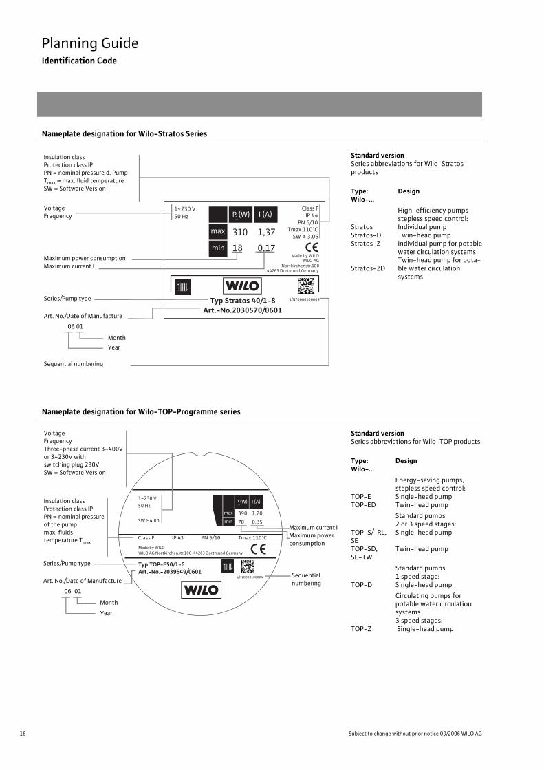
Nameplate designation for Wilo-Stratos Series
Standard versionSeries abbreviations for Wilo-Stratos products
Type:Wilo-...
Design
StratosStratos-DStratos-Z
Stratos-ZD
High-efficiency pumpsstepless speed control:Individual pumpTwin-head pumpIndividual pump for potable water circulation systemsTwin-head pump for pota-ble water circulationsystems
Nameplate designation for Wilo-TOP-Programme series
Standard versionSeries abbreviations for Wilo-TOP products
Type:Wilo-...
Design
TOP-ETOP-ED
Energy-saving pumps,stepless speed control:Single-head pumpTwin-head pump
TOP-S/-RL, SETOP-SD, SE-TW
Standard pumps2 or 3 speed stages:Single-head pump
Twin-head pump
TOP-D
Standard pumps1 speed stage:Single-head pump
TOP-Z
Circulating pumps for potable water circulation systems3 speed stages: Single-head pump
Typ Stratos 40/1-8Art.-No.2030570/0601
1~230 V
50 Hz
Class F
IP 44
PN 6/10
Tmax.110°C
SW 3.06
Made by WILO
WILO AG
Nortkirchenstr.100
44263 Dortmund Germany
S/N70000100008
310 1,37
18 0,17
Insulation classProtection class IPPN = nominal pressure d. PumpTmax = max. fluid temperatureSW = Software Version
VoltageFrequency
Maximum power consumptionMaximum current I
Series/Pump type
Art. No./Date of Manufacture 06 01
Month Year
Sequential numbering
Typ TOP-E50/1-6Art.-No.-2039649/0601
1~230 V
50 Hz
SW 4.00
Made by WILO
WILO AG Nortkirchenstr.100 44263 Dortmund Germany
Class F IP 43
S/N20000100004
PN 6/10 Tmax 110°C
390 1,70
70 0,35
Insulation classProtection class IPPN = nominal pressureof the pumpmax. fluidstemperature Tmax
VoltageFrequencyThree-phase current 3~400V or 3~230V with switching plug 230VSW = Software Version
Maximum current IMaximum power consumption
Series/Pump type
Art. No./Date of Manufacture 06 01
Month
Year
Sequential numbering
17
Planning GuideIdentification Code
Wilo Catalogue A1 - Circulating pumps in glandless design
Hea
tin
g, A
ir-c
on
dit
ion
ing
, C
oo
ling
Po
tab
le w
ater
cir
cula
tio
nSo
lar
ther
mal
Serv
ice/
Acc
esso
ries
, Sys
tem
sSw
itch
gea
rs a
nd
Co
ntr
ol
Dev
ices
P
um
p M
anag
emen
t S y
stem
s
Non-standard versionsSeveral pumps can be supplied in the following non-standard versions at additional charge, if desired
(the type of the special version is marked on the name plate):
- PN 10 Maximum permitted pump operating pressure
- RG Red bronze version
Example:Star-RS 25/4 RG = Star-RS 25/4 with red-bronze housing
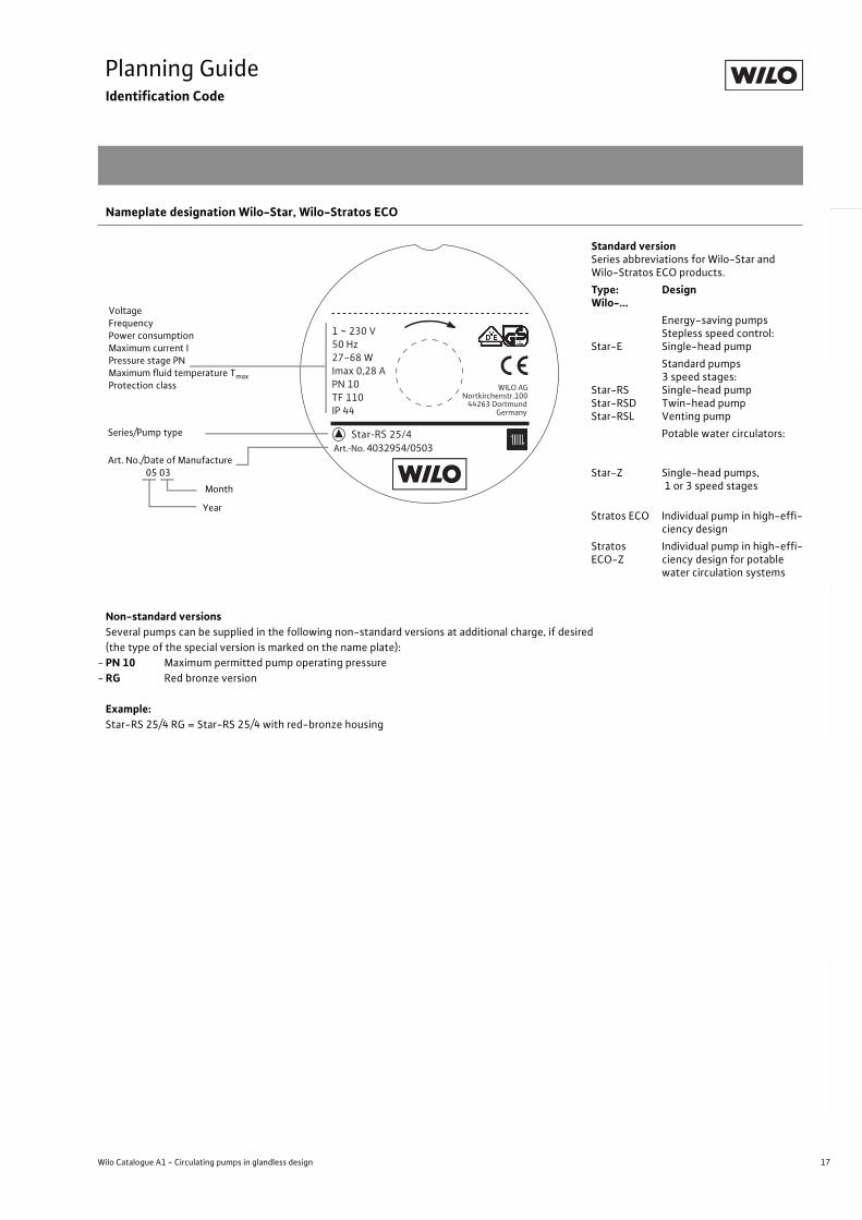
Nameplate designation Wilo-Star, Wilo-Stratos ECO
Standard versionSeries abbreviations for Wilo-Star and Wilo-Stratos ECO products.
Type:Wilo-...
Design
Star-E
Energy-saving pumpsStepless speed control:Single-head pump
Star-RSStar-RSDStar-RSL
Standard pumps3 speed stages:Single-head pumpTwin-head pumpVenting pump
Potable water circulators:
Star-Z Single-head pumps, 1 or 3 speed stages
Stratos ECO Individual pump in high-effi-ciency design
Stratos ECO-Z
Individual pump in high-effi-ciency design for potable water circulation systems
Art.-No. 4032954/0503Star-RS 25/4
1 ~ 230 V
50 Hz
27-68 W
Imax 0,28 A
PN 10
TF 110
IP 44
WILO AGNortkirchenstr.100 44263 Dortmund Germany
VoltageFrequencyPower consumptionMaximum current IPressure stage PNMaximum fluid temperature Tmax
Protection class
Series/Pump type
Art. No./Date of Manufacture 05 03 Month
Year
18 Subject to change without prior notice 09/2006 WILO AG
Planning GuideIdentification Code
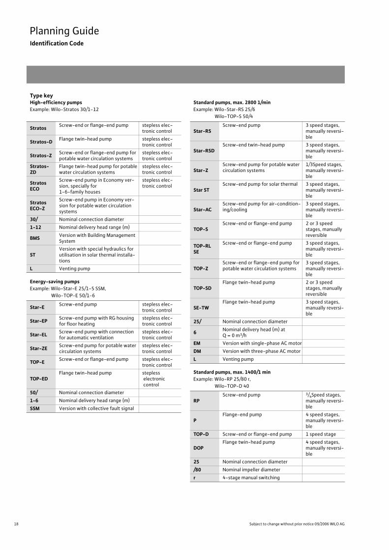
Type keyHigh-efficiency pumpsExample: Wilo-Stratos 30/1-12
Energy-saving pumpsExample: Wilo-Star-E 25/1-5 SSM,
Wilo-TOP-E 50/1-6
Standard pumps, max. 2800 1/minExample: Wilo-Star-RS 25/6
Wilo-TOP-S 50/4
Standard pumps, max. 1400/1 minExample: Wilo-RP 25/80 r,
Wilo-TOP-D 40
StratosScrew-end or flange-end pump stepless elec-
tronic control
Stratos-DFlange twin-head pump stepless elec-
tronic control
Stratos-ZScrew-end or flange-end pump for potable water circulation systems
stepless elec-tronic control
Stratos-ZD
Flange twin-head pump for potable water circulation systems
stepless elec-tronic control
Stratos ECO
Screw-end pump in Economy ver-sion, specially for 1-6-family houses
stepless elec-tronic control
Stratos ECO-Z
Screw-end pump in Economy ver-sion for potable water circulation systems
30/ Nominal connection diameter
1-12 Nominal delivery head range (m)
BMSVersion with Building Management System
STVersion with special hydraulics for utilisation in solar thermal installa-tions
L Venting pump
Star-EScrew-end pump stepless elec-
tronic control
Star-EPScrew-end pump with RG housing for floor heating
stepless elec-tronic control
Star-ELScrew-end pump with connection for automatic ventilation
stepless elec-tronic control
Star-ZEScrew-end pump for potable water circulation systems
stepless elec-tronic control
TOP-EScrew-end or flange-end pump stepless elec-
tronic control
TOP-EDFlange twin-head pump stepless
electronic control
50/ Nominal connection diameter
1-6 Nominal delivery head range (m)
SSM Version with collective fault signal
Star-RSScrew-end pump 3 speed stages,
manually reversi-ble
Star-RSDScrew-end twin-head pump 3 speed stages,
manually reversi-ble
Star-ZScrew-end pump for potable water circulation systems
1/3Speed stages,manually reversi-ble
Star STScrew-end pump for solar thermal 3 speed stages,
manually reversi-ble
Star-ACScrew-end pump for air-condition-ing/cooling
3 speed stages, manually reversi-ble
TOP-SScrew-end or flange-end pump 2 or 3 speed
stages, manually reversible
TOP-RL SE
Screw-end or flange-end pump 3 speed stages, manually reversi-ble
TOP-ZScrew-end or flange-end pump for potable water circulation systems
3 speed stages, manually reversi-ble
TOP-SDFlange twin-head pump 2 or 3 speed
stages, manually reversible
SE-TWFlange twin-head pump 3 speed stages,
manually reversi-ble
25/ Nominal connection diameter
6Nominal delivery head (m) at Q = 0 m3/h
EM Version with single-phase AC motor
DM Version with three-phase AC motor
L Venting pump
RPScrew-end pump 3/4Speed stages,
manually reversi-ble
PFlange-end pump 4 speed stages,
manually reversi-ble
TOP-D Screw-end or flange-end pump 1 speed stage
DOPFlange twin-head pump 4 speed stages,
manually reversi-ble
25 Nominal connection diameter
/80 Nominal impeller diameter
r 4-stage manual switching
19
Planning GuideEnergy efficiency classification
Wilo Catalogue A1 - Circulating pumps in glandless design
Hea
tin
g, A
ir-c
on
dit
ion
ing
, C
oo
ling
Po
tab
le w
ater
cir
cula
tio
nSo
lar
ther
mal
Serv
ice/
Acc
esso
ries
, Sys
tem
sSw
itch
gea
rs a
nd
Co
ntr
ol
Dev
ices
P
um
p M
anag
emen
t S y
stem
s
Energy efficiency classification
Within the framework of the Kyoto Convention, European govern-
ments in particular are pursuing the goal of drastically reducing CO2
emissions. Energy-specific designations, particularly for high-con-
sumption household devices such as washing machines and refriger-
ators, is prescribed as an important control element for providing the
end consumer with an aid for making decisions in favour of energy-
saving appliances.
Because of the fact that heating circulating pumps are numbered
among the biggest energy consumers in household use because of
their long running times, leading European heating pump manufac-
turers have voluntarily declared their intention of henceforth attach-
ing energy consumption labels to their heating pumps. This makes it
possible for users and end consumers to recognise, on the basis of an
already familiar classification system, to recognise whether a heating
circulating pump being utilised is especially energy-efficient.
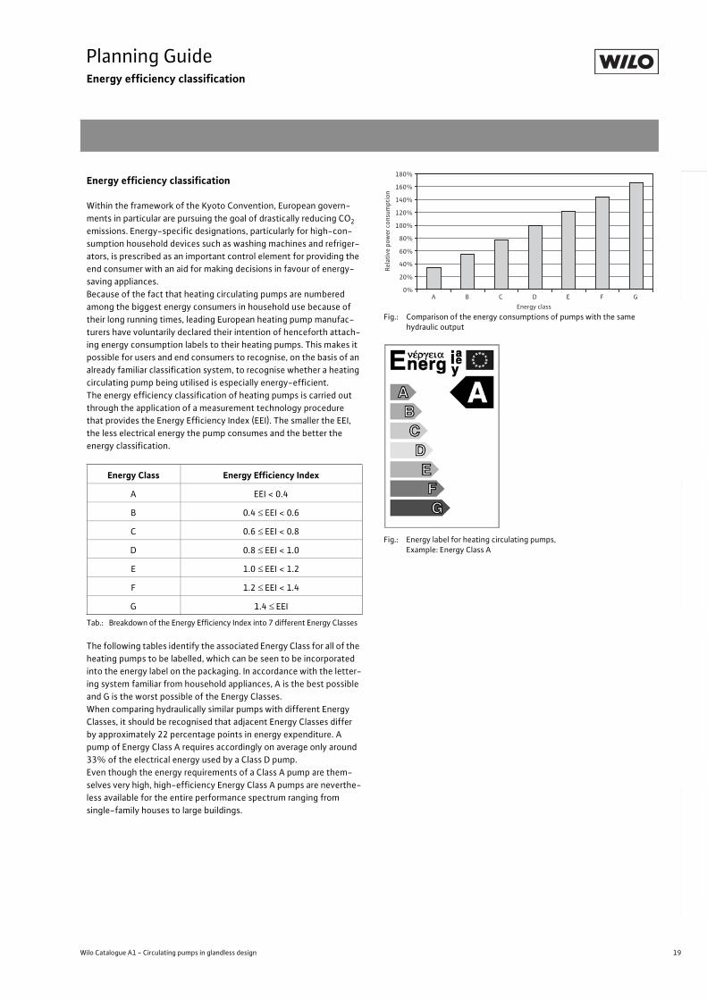
The energy efficiency classification of heating pumps is carried out
through the application of a measurement technology procedure
that provides the Energy Efficiency Index (EEI). The smaller the EEI,
the less electrical energy the pump consumes and the better the
energy classification.
Tab.: Breakdown of the Energy Efficiency Index into 7 different Energy Classes
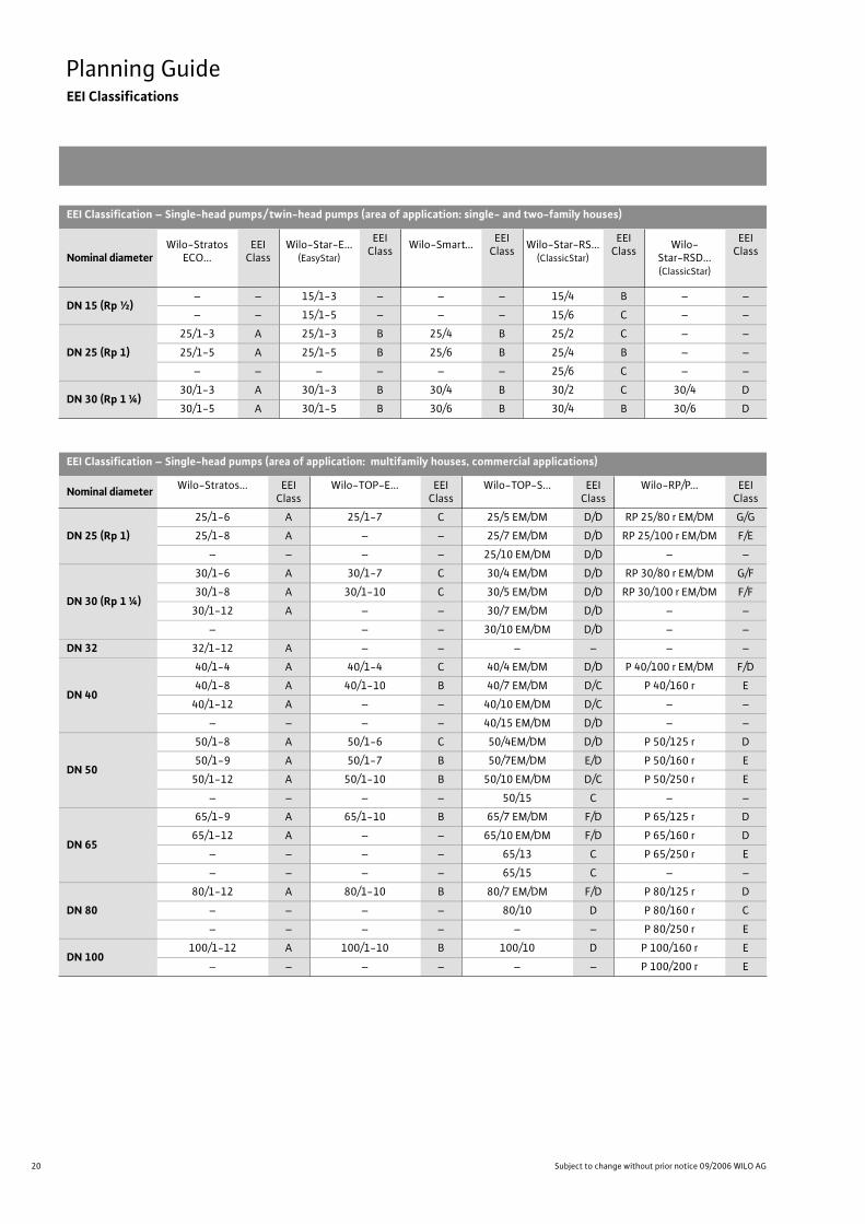
The following tables identify the associated Energy Class for all of the
heating pumps to be labelled, which can be seen to be incorporated
into the energy label on the packaging. In accordance with the letter-
ing system familiar from household appliances, A is the best possible
and G is the worst possible of the Energy Classes.
When comparing hydraulically similar pumps with different Energy
Classes, it should be recognised that adjacent Energy Classes differ
by approximately 22 percentage points in energy expenditure. A
pump of Energy Class A requires accordingly on average only around
33% of the electrical energy used by a Class D pump.
Even though the energy requirements of a Class A pump are them-
selves very high, high-efficiency Energy Class A pumps are neverthe-
less available for the entire performance spectrum ranging from
single-family houses to large buildings.
Fig.: Comparison of the energy consumptions of pumps with the same hydraulic output
Fig.: Energy label for heating circulating pumps,Example: Energy Class A
Energy Class Energy Efficiency Index
A EEI < 0.4
B 0.4 EEI < 0.6
C 0.6 EEI < 0.8
D 0.8 EEI < 1.0
E 1.0 EEI < 1.2
F 1.2 EEI < 1.4
G 1.4 EEI
0%
20%
40%
60%
80%
100%
120%
140%
160%
180%
A B C D E F G
Energy class
Re
lati
ve
po
we
r c
on
sum
pti
on
20 Subject to change without prior notice 09/2006 WILO AG
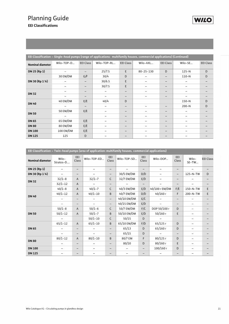
Planning GuideEEI Classifications
EEI Classification – Single-head pumps/ twin-head pumps (area of application: single- and two-family houses)
Nominal diameterWilo-Stratos
ECO...EEI
ClassWilo-Star-E...
(EasyStar)
EEI Class
Wilo-Smart...EEI
ClassWilo-Star-RS...
(ClassicStar)
EEI Class
Wilo-Star-RSD...(ClassicStar)
EEI Class
DN 15 (Rp ½)– – 15/1-3 – – – 15/4 B – –
– – 15/1-5 – – – 15/6 C – –
DN 25 (Rp 1)
25/1-3 A 25/1-3 B 25/4 B 25/2 C – –
25/1-5 A 25/1-5 B 25/6 B 25/4 B – –
– – – – – – 25/6 C – –
DN 30 (Rp 1 ¼)30/1-3 A 30/1-3 B 30/4 B 30/2 C 30/4 D
30/1-5 A 30/1-5 B 30/6 B 30/4 B 30/6 D
EEI Classification – Single-head pumps (area of application: multifamily houses, commercial applications)
Nominal diameterWilo-Stratos... EEI
ClassWilo-TOP-E... EEI
ClassWilo-TOP-S... EEI
ClassWilo-RP/P... EEI
Class
DN 25 (Rp 1)
25/1-6 A 25/1-7 C 25/5 EM/DM D/D RP 25/80 r EM/DM G/G
25/1-8 A – – 25/7 EM/DM D/D RP 25/100 r EM/DM F/E
– – – – 25/10 EM/DM D/D – –
DN 30 (Rp 1 ¼)
30/1-6 A 30/1-7 C 30/4 EM/DM D/D RP 30/80 r EM/DM G/F
30/1-8 A 30/1-10 C 30/5 EM/DM D/D RP 30/100 r EM/DM F/F
30/1-12 A – – 30/7 EM/DM D/D – –
– – – 30/10 EM/DM D/D – –
DN 32 32/1-12 A – – – – – –
DN 40
40/1-4 A 40/1-4 C 40/4 EM/DM D/D P 40/100 r EM/DM F/D
40/1-8 A 40/1-10 B 40/7 EM/DM D/C P 40/160 r E
40/1-12 A – – 40/10 EM/DM D/C – –
– – – – 40/15 EM/DM D/D – –
DN 50
50/1-8 A 50/1-6 C 50/4EM/DM D/D P 50/125 r D
50/1-9 A 50/1-7 B 50/7EM/DM E/D P 50/160 r E
50/1-12 A 50/1-10 B 50/10 EM/DM D/C P 50/250 r E
– – – – 50/15 C – –
DN 65
65/1-9 A 65/1-10 B 65/7 EM/DM F/D P 65/125 r D
65/1-12 A – – 65/10 EM/DM F/D P 65/160 r D
– – – – 65/13 C P 65/250 r E
– – – – 65/15 C – –
DN 80
80/1-12 A 80/1-10 B 80/7 EM/DM F/D P 80/125 r D
– – – – 80/10 D P 80/160 r C
– – – – – – P 80/250 r E
DN 100100/1-12 A 100/1-10 B 100/10 D P 100/160 r E
– – – – – – P 100/200 r E
21
Planning GuideEEI Classifications
Wilo Catalogue A1 - Circulating pumps in glandless design
Hea
tin
g, A
ir-c
on
dit
ion
ing
, C
oo
ling
Po
tab
le w
ater
cir
cula
tio
nSo
lar
ther
mal
Serv
ice/
Acc
esso
ries
, Sys
tem
sSw
itch
gea
rs a
nd
Co
ntr
ol
Dev
ices
P
um
p M
anag
emen
t S y
stem
s
EEI Classification – Single-head pumps (range of applications: multifamily houses, commercial applications) (Continued)
Nominal diameterWilo-TOP-D... EEI Class Wilo-TOP-RL... EEI Class Wilo-AXL... EEI Class Wilo-SE... EEI Class
DN 25 (Rp 1) – – 25/7.5 E 80-25-130 D 125-N D
DN 30 (Rp 1 ¼)
30 EM/DM G/F 30/4 D – – 110-N D
– – 30/6.5 E – – – –
– – 30/7.5 E – – – –
DN 32– – – – – – – –
– – – – – – – –
DN 4040 EM/DM E/E 40/4 D 150-N D
– – – – – – 200-N D
DN 5050 EM/DM E/E – – – – – –
– – – – – – –
DN 65 65 EM/DM E/E – – – – – –
DN 80 80 EM/DM E/E – – – – – –
DN 100 100 EM/DM E/E – – – – – –
DN 125 125 D – – – – – –
EEI Classification – Twin-head pumps (area of application: multifamily houses, commercial applications)
Nominal diameterWilo-
Stratos-D....
EEI Class
Wilo-TOP-ED...EEI
ClassWilo-TOP-SD...
EEI Class
Wilo-DOP...EEI
ClassWilo-
SE-TW...EEI Class
DN 25 (Rp 1) – – – – – – – – – –
DN 30 (Rp 1 ¼) – – – – 30/5 EM/DM D/D – – 125-N-TW D
DN 3232/1-8 A 32/1-7 C 32/7 EM/DM E/D – – – –
32/1-12 A – – – – – – – –
DN 40
40/1-8 A 40/1-7 C 40/3 EM/DM E/D 40/100 r EM/DM F/E 150-N-TW E
40/1-12 A 40/1-10 B 40/7 EM/DM D/D 40/160 r F 200-N-TW E
– – – – 40/10 EM/DM E/C – – – –
– – – – 40/15 EM/DM E/D – – – –
DN 50
50/1-8 A 50/1-6 C 50/7 EM/DM F/C DOP 50/100 r D – –
50/1-12 A 50/1-7 B 50/10 EM/DM E/D 50/160 r E – –
– 50/1-10 C 50/15 D – – –
DN 65
65/1-12 A 65/1-10 B 65/10 EM/DM F/D 65/125 r D – –
– – – – 65/13 D 65/160 r D – –
– – – – 65/15 D – – – –
DN 8080/1-12 A 80/1-10 B 80/7 EM F 80/125 r D – –
– – – – 80/10 D 80/160 r E – –
DN 100 – – – – – – 100/160 r D – –
DN 125 – – – – – – – – – –
22 Subject to change without prior notice 09/2006 WILO AG
Planning GuideHigh-Efficiency Pumps
Wilo-Stratos/Stratos-Z/Stratos-D/Stratos-ZD
Planning guide:Wilo-Stratos/Stratos-Z/Stratos-D/Stratos-ZDWilo-Stratos is the first high-efficiency pump of glandless design
world-wide to feature the following advantages:
- up to 80 % energy savings compared to standard pumps
- for all heating, air-conditioning and cooling systems in the tempera-
ture range of -10 °C to +110 °C
- automatic adjustment of pump performance to the continually
changing hydraulic system load conditions
- preventing flow noise
- reliability and comfort during installation and operation
Fields Of applicationThe Wilo-Stratos series features high-efficiency pumps used in cir-
culation systems for the heating, ventilating, air conditioning of
commercial residential and functional buildings:
- Large residential buildings
- Apartment blocks
- Residential complexes
- Hospitals
- Schools
- Administrative office buildings
- Real-estate developments
Temperature rangeFluid temperature range of -10 °C to +110 °C without restrictions at
ambient temperatures of 0 °C to a max. of + 40 °C.
Heating applicationIn nearly all circulation systems, correctly sized controlled glandless
pumps ensure adequate heat supply at all times at significantly
reduced energy costs, while at the same time preventing noise gen-
eration.
Since the introduction of the German energy-saving ordinance (EnEV) of 01.01.2002, heating circulating pumps with nominal thermal outputs of 25 kW or more are required to include control units.On account of its corrosion-resistant red bronze pump housing,
Wilo-Stratos-Z are particularly suitable for systems subject to the
possible ingress of oxygen, such as e.g. floor heating systems made
of plastic piping.
Thermal insulation for heatingIn order to prevent thermal losses through the pump housing, Wilo-
Stratos/-Stratos-Z series single-head pumps are standard-equipped
with thermal insulation shells. The PP material used, foamed polypro-
pylene, has the following properties:
- Environmental compatibility: easily recyclable
- Heat resistance: up to 120 °C
- Transmission coefficient: 0.04 W/mK according to DIN 52612
- Flammability: Class B2 4102in accordance with DIN (normal flamma-
bility)
In Germany, normally flammable materials can, in accordance with
fire protection regulations, be used in boiler rooms as long as a mini-
mum distance of 20 cm from the burner is maintained.
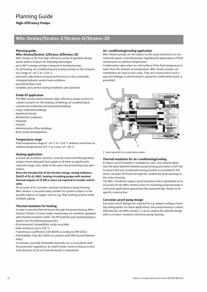
Air-conditioning/cooling applicationWilo-Stratos pumps are not subject to the usual restrictions on con-
ventional speed-controlled pumps regarding the dependency of fluid
temperature on ambient temperature.
Condensation takes place on cold surfaces if the fluid temperature is
lower than the ambient air temperature. Wilo-Stratos pumps can
nonetheless be used in such cases. They are constructed in such a
way that damage to electrical parts caused by condensation water is
prevented.
1 drain labyrinth for condensation water
Thermal insulation for air-conditioning/coolingIf vapour-proof insulation is installed on-site, care must be taken
that the drain labyrinth between pump housing and motor is left free
to ensure that any condensate having possibly accumulated in the
motor can drain off freely through the condensate drain openings in
the motor housing.
The Wilo-ClimaForm vapour-proof insulation that is obtainable as an
accessory for the Wilo-Stratos series for insulating pump housings in
cold water applications guarantees this automatically, thanks to its
specific construction.
Corrosion-proof pump designCorrosion-proof designs are required for e.g. radiant cooling or heat-
ing ceiling panels. For these applications, the pump housing is coated.
Alternatively, the Wilo-Stratos-Z can be used as the ultimate design
with a corrosion-resistant red bronze pump housing.
1
23
Planning GuideHigh-Efficiency Pumps
Wilo-Stratos/Stratos-Z/Stratos-D/Stratos-ZD
Wilo Catalogue A1 - Circulating pumps in glandless design
Hea
tin
g, A
ir-c
on
dit
ion
ing
, C
oo
ling
Po
tab
le w
ater
cir
cula
tio
nSo
lar
ther
mal
Serv
ice/
Acc
esso
ries
, Sys
tem
sSw
itch
gea
rs a
nd
Co
ntr
ol
Dev
ices
P
um
p M
anag
emen
t S y
stem
s
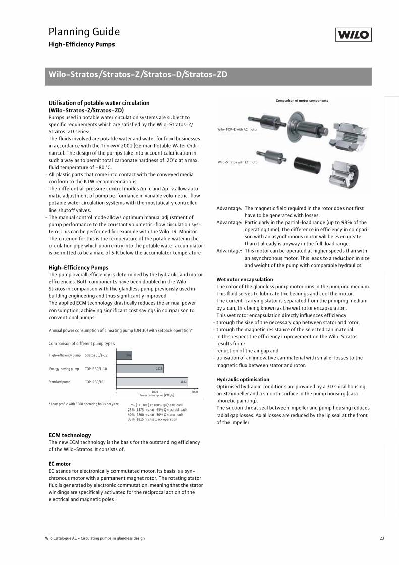
Utilisation of potable water circulation (Wilo-Stratos-Z/Stratos-ZD)Pumps used in potable water circulation systems are subject to
specific requirements which are satisfied by the Wilo-Stratos-Z/
Stratos-ZD series:
- The fluids involved are potable water and water for food businesses
in accordance with the TrinkwV 2001 (German Potable Water Ordi-
nance). The design of the pumps take into account calcification in
such a way as to permit total carbonate hardness of 20°d at a max.
fluid temperature of +80 °C.
- All plastic parts that come into contact with the conveyed media
conform to the KTW recommendations.
- The differential-pressure control modes p-c and p-v allow auto-
matic adjustment of pump performance in variable volumetric-flow
potable water circulation systems with thermostatically controlled
line shutoff valves.
- The manual control mode allows optimum manual adjustment of
pump performance to the constant volumetric-flow circulation sys-
tem. This can be performed for example with the Wilo-IR-Monitor.
The criterion for this is the temperature of the potable water in the
circulation pipe which upon entry into the potable water accumulator
is permitted to be a max. of 5 K below the accumulator temperature
High-Efficiency PumpsThe pump overall efficiency is determined by the hydraulic and motor
efficiencies. Both components have been doubled in the Wilo-
Stratos in comparison with the glandless pump previously used in
building engineering and thus significantly improved.
The applied ECM technology drastically reduces the annual power
consumption, achieving significant cost savings in comparison to
conventional pumps.
ECM technologyThe new ECM technology is the basis for the outstanding efficiency
of the Wilo-Stratos. It consists of:
EC motorEC stands for electronically commutated motor. Its basis is a syn-
chronous motor with a permanent magnet rotor. The rotating stator
flux is generated by electronic commutation, meaning that the stator
windings are specifically activated for the reciprocal action of the
electrical and magnetic poles.
Advantage: The magnetic field required in the rotor does not first
have to be generated with losses.
Advantage: Particularly in the partial-load range (up to 98% of the
operating time), the difference in efficiency in compari-
son with an asynchronous motor will be even greater
than it already is anyway in the full-load range.
Advantage: This motor can be operated at higher speeds than with
an asynchronous motor. This leads to a reduction in size
and weight of the pump with comparable hydraulics.
Wet rotor encapsulationThe rotor of the glandless pump motor runs in the pumping medium.
This fluid serves to lubricate the bearings and cool the motor.
The current-carrying stator is separated from the pumping medium
by a can, this being known as the wet rotor encapsulation.
This wet rotor encapsulation directly influences efficiency
- through the size of the necessary gap between stator and rotor,
- through the magnetic resistance of the selected can material.
- In this respect the efficiency improvement on the Wilo-Stratos
results from:
- reduction of the air gap and
- utilisation of an innovative can material with smaller losses to the
magnetic flux between stator and rotor.
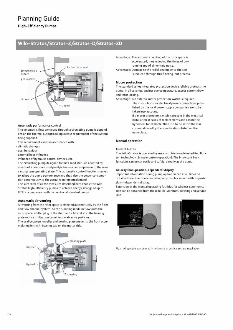
Hydraulic optimisationOptimised hydraulic conditions are provided by a 3D spiral housing,
an 3D impeller and a smooth surface in the pump housing (cata-
phoretic painting).
The suction throat seal between impeller and pump housing reduces
radial gap losses. Axial losses are reduced by the lip seal at the front
of the impeller.
Planning GuideHigh-Efficiency PumpsWilo-Stratos/Stratos-Z/Stra-tos-D/Stratos-ZD
Annual power consumption of a heating pump (DN 30) with setback operation*
Comparison of different pump types
High-efficiency pump Stratos 30/1-12
Energy-saving pump TOP-E 30/1-10
Standard pump TOP-S 30/10
* Load profile with 5500 operating hours per year:
1832
0 1000 2000Power consumption [kWh/a]
1216
396
2% (110 hrs.) at 100% QN(peak load)25% (1375 hrs.) at 65% Q N(partial load)40% (2200 hrs.) at 30% Q N(low load)33% (1815 hrs.) setback operation
Wilo-Stratos with EC motor
Wilo-TOP-E with AC motor
Comparison of motor components
24 Subject to change without prior notice 09/2006 WILO AG
Planning GuideHigh-Efficiency Pumps
Wilo-Stratos/Stratos-Z/Stratos-D/Stratos-ZD
Automatic performance controlThe volumetric flow conveyed through a circulating pump is depend-
ent on the thermal output/cooling output requirement of the system
being supplied.
This requirement varies in accordance with
- climatic changes
- user behaviour
- external heat influence
- influence of hydraulic control devices, etc.
The circulating pump designed for max. load status is adapted by
means of a continuous setpoint/actual-value comparison to the rele-
vant system operating state. This automatic control functions serves
to adapt the pump performance and thus also the power consump-
tion continuously to the actual requirement/demand.
The sum total of all the measures described here enable the Wilo-
Stratos high-efficiency pumps to achieve energy savings of up to
80% in comparison with conventional standard pumps.
Automatic air ventingAir venting from the rotor space is effected automatically by the filter
and flow channel system. As the pumping medium flows into the
rotor space, a filter plug in the shaft and a filter disc in the bearing
plate reduce infiltration by miniscule abrasive particles.
The seal between impeller and bearing plate prevents dirt from accu-
mulating in the A-bearing gap on the motor side.
Advantage: The automatic venting of the rotor space is
accelerated, thus reducing the times of dry-
running and of air venting noise.
Advantage: Damage to the radial bearing or to the can
is reduced through this filtering-out process.
Motor protectionThe standard series integrated protection device reliably protects the
pump, in all settings, against overtemperature, excess current draw
and rotor locking.
Advantage: No external motor protection switch is required.
The instructions for electrical power connections pub-
lished by the local power supply companies are to be
taken into account.
If a motor protection switch is present in the electrical
installation in cases of replacements and can not be
bypassed, for example, then it is to be set to the max.
current allowed by the specifications listed on the
nameplate.
Manual operation
Control buttonThe Wilo-Stratos is operated by means of tried-and-tested Red But-
ton technology (1single-button operation). The important basic
functions can be set easily and safely, directly at the pump.
All-way (non-position-dependent) displayImportant information during pump operation can at all times be
obtained from the front-readable pump display screen with its posi-
tion-independent display.
Extension of the manual operating facilities for wireless communica-
tion can be obtained from the Wilo-IR-Monitor Operating and Service
Unit.
Fig.: All symbols can be read in horizontal or vertical set-up installation
3-D spiral
Suction throat seal
Lip seal
3-D impeller
Smooth inside surface
Lip seal
Impeller
A-bearing
Bearing plate
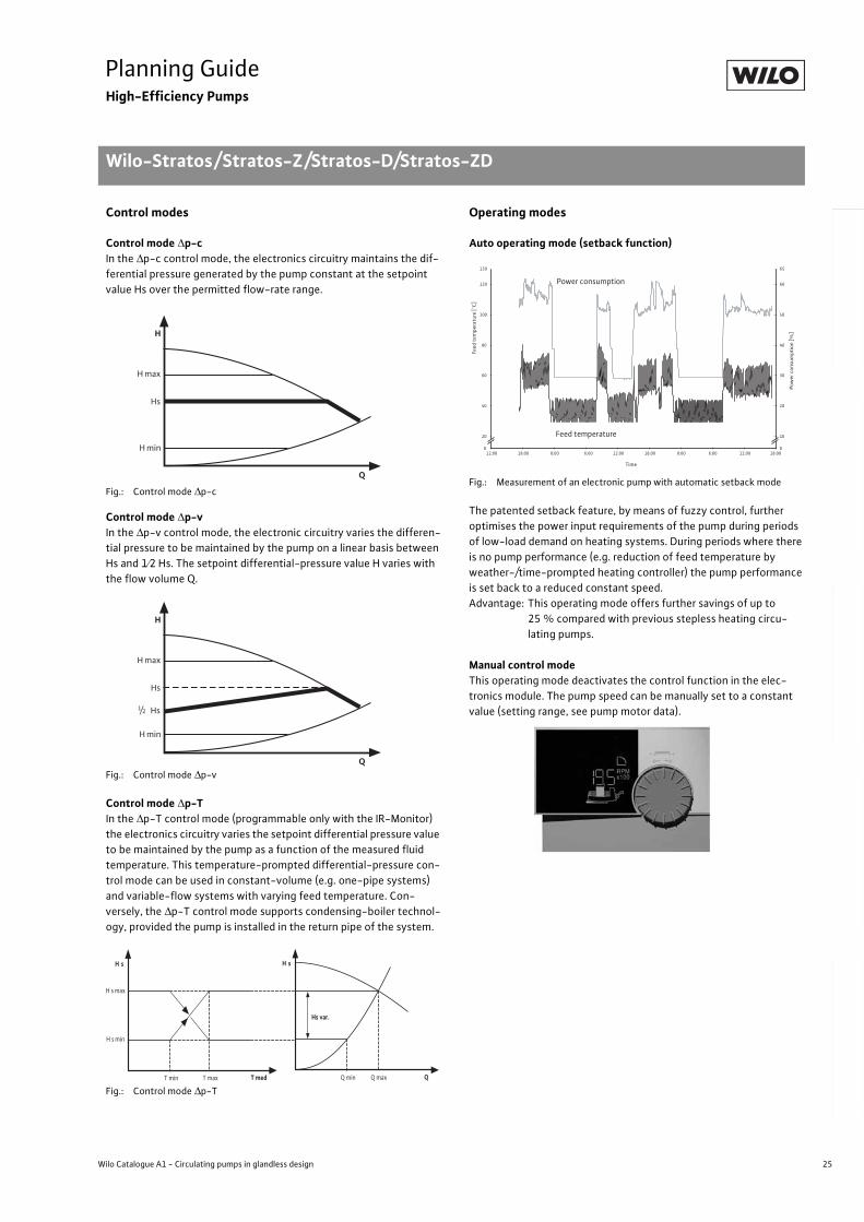
25
Planning GuideHigh-Efficiency Pumps
Wilo-Stratos/Stratos-Z/Stratos-D/Stratos-ZD
Wilo Catalogue A1 - Circulating pumps in glandless design
Hea
tin
g, A
ir-c
on
dit
ion
ing
, C
oo
ling
Po
tab
le w
ater
cir
cula
tio
nSo
lar
ther
mal
Serv
ice/
Acc
esso
ries
, Sys
tem
sSw
itch
gea
rs a
nd
Co
ntr
ol
Dev
ices
P
um
p M
anag
emen
t S y
stem
s
Control modes
Control mode p-cIn the p-c control mode, the electronics circuitry maintains the dif-
ferential pressure generated by the pump constant at the setpoint
value Hs over the permitted flow-rate range.
Fig.: Control mode p-c
Control mode p-vIn the p-v control mode, the electronic circuitry varies the differen-
tial pressure to be maintained by the pump on a linear basis between
Hs and 1 2 Hs. The setpoint differential-pressure value H varies with
the flow volume Q.
Fig.: Control mode p-v
Control mode p-TIn the p-T control mode (programmable only with the IR-Monitor)
the electronics circuitry varies the setpoint differential pressure value
to be maintained by the pump as a function of the measured fluid
temperature. This temperature-prompted differential-pressure con-
trol mode can be used in constant-volume (e.g. one-pipe systems)
and variable-flow systems with varying feed temperature. Con-
versely, the p-T control mode supports condensing-boiler technol-
ogy, provided the pump is installed in the return pipe of the system.
Fig.: Control mode p-T
Operating modes
Auto operating mode (setback function)
Fig.: Measurement of an electronic pump with automatic setback mode
The patented setback feature, by means of fuzzy control, further
optimises the power input requirements of the pump during periods
of low-load demand on heating systems. During periods where there
is no pump performance (e.g. reduction of feed temperature by
weather-/time-prompted heating controller) the pump performance
is set back to a reduced constant speed.
Advantage: This operating mode offers further savings of up to
25 % compared with previous stepless heating circu-
lating pumps.
Manual control modeThis operating mode deactivates the control function in the elec-
tronics module. The pump speed can be manually set to a constant
value (setting range, see pump motor data).
H max
H
H min
Hs
Q
H max
H
H min
Hs
Q
Hs1/2
H s min
H s
Hs var.
QQ min Q max
H s
T medT min T max
H s max
Pow
er c
onsu
mpt
ion
[%]
0
20
40
60
80
100
120
130
12:00 18:00 0:00 6:00 12:00 18:00 0:00 6:00 12:00 18:00
Time
0
10
20
30
40
50
60
65
Power consumption
Feed temperature
Feed
tem
pera
ture
[°C
]
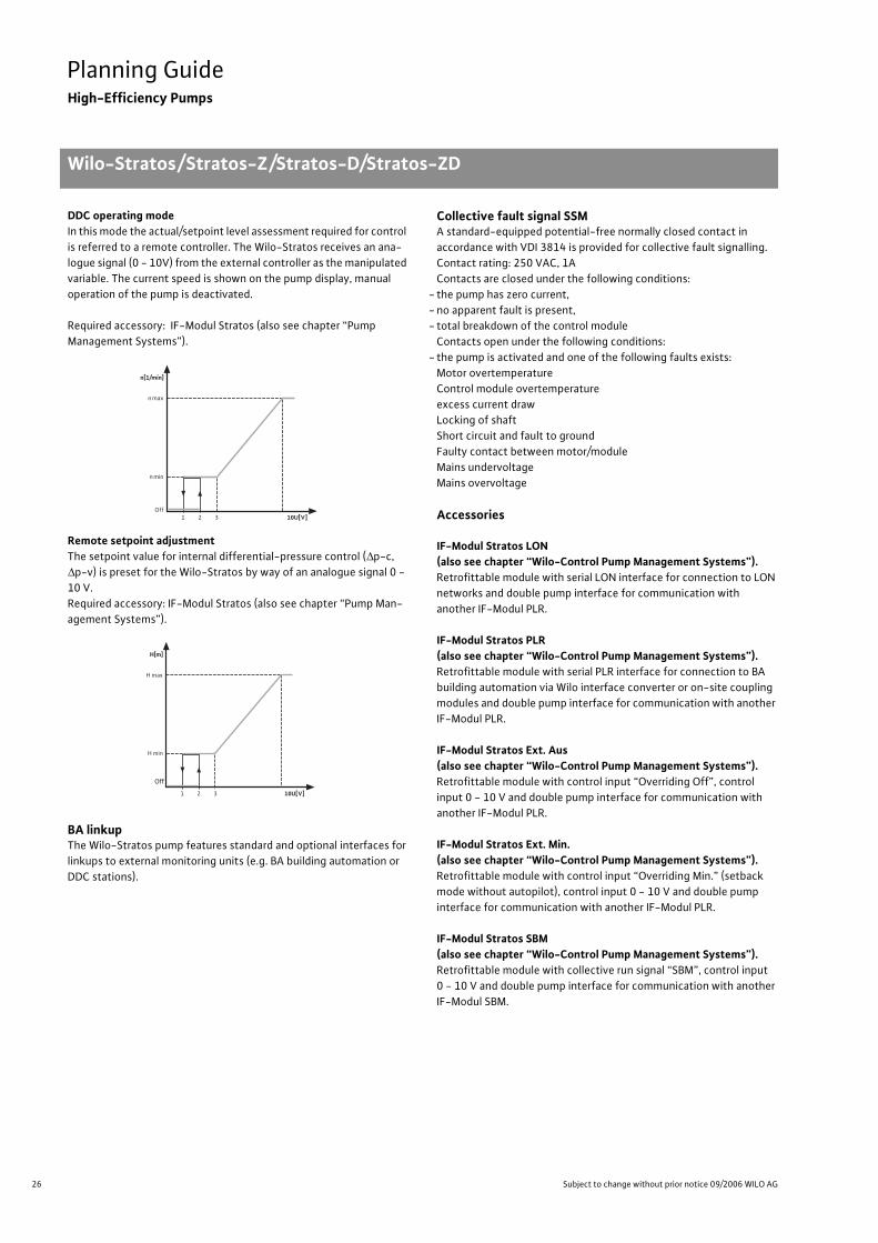
26 Subject to change without prior notice 09/2006 WILO AG
Planning GuideHigh-Efficiency Pumps
Wilo-Stratos/Stratos-Z/Stratos-D/Stratos-ZD
DDC operating modeIn this mode the actual/setpoint level assessment required for control
is referred to a remote controller. The Wilo-Stratos receives an ana-
logue signal (0 - 10V) from the external controller as the manipulated
variable. The current speed is shown on the pump display, manual
operation of the pump is deactivated.
Required accessory: IF-Modul Stratos (also see chapter “Pump
Management Systems”).
Remote setpoint adjustmentThe setpoint value for internal differential-pressure control ( p-c,
p-v) is preset for the Wilo-Stratos by way of an analogue signal 0 -
10 V.
Required accessory: IF-Modul Stratos (also see chapter “Pump Man-
agement Systems”).
BA linkupThe Wilo-Stratos pump features standard and optional interfaces for
linkups to external monitoring units (e.g. BA building automation or
DDC stations).
Collective fault signal SSMA standard-equipped potential-free normally closed contact in
accordance with VDI 3814 is provided for collective fault signalling.
Contact rating: 250 VAC, 1A
Contacts are closed under the following conditions:
- the pump has zero current,
- no apparent fault is present,
- total breakdown of the control module
Contacts open under the following conditions:
- the pump is activated and one of the following faults exists:
Motor overtemperature
Control module overtemperature
excess current draw
Locking of shaft
Short circuit and fault to ground
Faulty contact between motor/module
Mains undervoltage
Mains overvoltage
Accessories
IF-Modul Stratos LON (also see chapter “Wilo-Control Pump Management Systems”).Retrofittable module with serial LON interface for connection to LON
networks and double pump interface for communication with
another IF-Modul PLR.
IF-Modul Stratos PLR(also see chapter “Wilo-Control Pump Management Systems”).Retrofittable module with serial PLR interface for connection to BA
building automation via Wilo interface converter or on-site coupling
modules and double pump interface for communication with another
IF-Modul PLR.
IF-Modul Stratos Ext. Aus(also see chapter “Wilo-Control Pump Management Systems”).Retrofittable module with control input “Overriding Off”, control
input 0 - 10 V and double pump interface for communication with
another IF-Modul PLR.
IF-Modul Stratos Ext. Min.(also see chapter “Wilo-Control Pump Management Systems”).Retrofittable module with control input “Overriding Min.” (setback
mode without autopilot), control input 0 - 10 V and double pump
interface for communication with another IF-Modul PLR.
IF-Modul Stratos SBM(also see chapter “Wilo-Control Pump Management Systems”).Retrofittable module with collective run signal “SBM”, control input
0 - 10 V and double pump interface for communication with another
IF-Modul SBM.
n[1/mín]
n max
n min
Off10U[V]1 32
H max
H min
Aus
H[m]
10U[V]1 32
Off
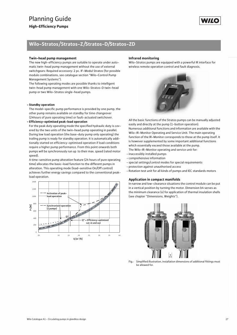
27
Planning GuideHigh-Efficiency Pumps
Wilo-Stratos/Stratos-Z/Stratos-D/Stratos-ZD
Wilo Catalogue A1 - Circulating pumps in glandless design
Hea
tin
g, A
ir-c
on
dit
ion
ing
, C
oo
ling
Po
tab
le w
ater
cir
cula
tio
nSo
lar
ther
mal
Serv
ice/
Acc
esso
ries
, Sys
tem
sSw
itch
gea
rs a
nd
Co
ntr
ol
Dev
ices
P
um
p M
anag
emen
t S y
stem
s
Twin-head pump managementThe new high-efficiency pumps are suitable to operate under auto-
matic twin-head pump management without the use of external
switchgears: Required accessory: 2 pc. IF-Modul Stratos (for possible
module combinations, see catalogue section “Wilo-Control Pump
Management Systems”).
The following operating modes are possible thanks to intelligent
twin-head pump management with one Wilo-Stratos-D twin-head
pump or two Wilo-Stratos single-head pumps.
- Standby operationThe model-specific pump performance is provided by one pump, the
other pump remains available on standby for time changeover
(24hours of pure operating time) or fault-actuated switchover.
- Efficiency-optimised peak-load operationFor the peak duty operating mode the specified hydraulic duty is cov-
ered by the two units of the twin-head pump operating in parallel.
During low load operation (the base-duty pump only operating) the
trailing pump is ready for standby operation. It is automatically addi-
tionally started on efficiency-optimised operation if load conditions
require a higher pump performance. From this point onwards both
pumps will be synchronously run up to their max. speed (rated motor
speed).
A time-sensitive pump alteration feature (24 hours of pure operating
time) allocates the basic-load function to the different pumps in
alteration. This operating mode (load-sensitive On/Off control)
achieves further energy savings compared to the conventional peak-
load operation.
Infrared monitoringWilo-Stratos pumps are equipped with a powerful IR interface for
wireless remote operation control and fault diagnosis.
All the basic functions of the Stratos pumps can be manually adjusted
easily and directly at the pump (1-button operation).
Numerous additional functions and information are available with the
Wilo-IR-Monitor Operating and Service Unit. The main operating
function of the IR-Monitor corresponds to those at the pump itself. It
is however supplemented by some important additional functions
which essentially exceed those available at the pump.
The Wilo-IR-Monitor operating and service unit for:
- inaccessibly installed pumps
- comprehensive information
- special settings/control modes for special requirements
- protection against unauthorised access
- Rotation test unit for all kinds of pumps and IEC standards motors
Application in compact manifoldsIn narrow and low-clearance situations the control module can be put
in a vertical position by turning the motor. Dimension b4 serves as
the minimum clearance (x) for application of thermal insulation shells
(see chapter “Dimensions, Weights”).
Fig.: Simplified illustration, installation dimensions of additional fittings must be allowed for.
0
200
400
600
800
1000
1200
1400
05 10 15 20 25 30 35 40
Q [m 3/h]
P1[
W]
Activation of peak-load operation
Q*
Synchronised operation (2 pumps)
Q* = Efficiency-optimised cut-in and out
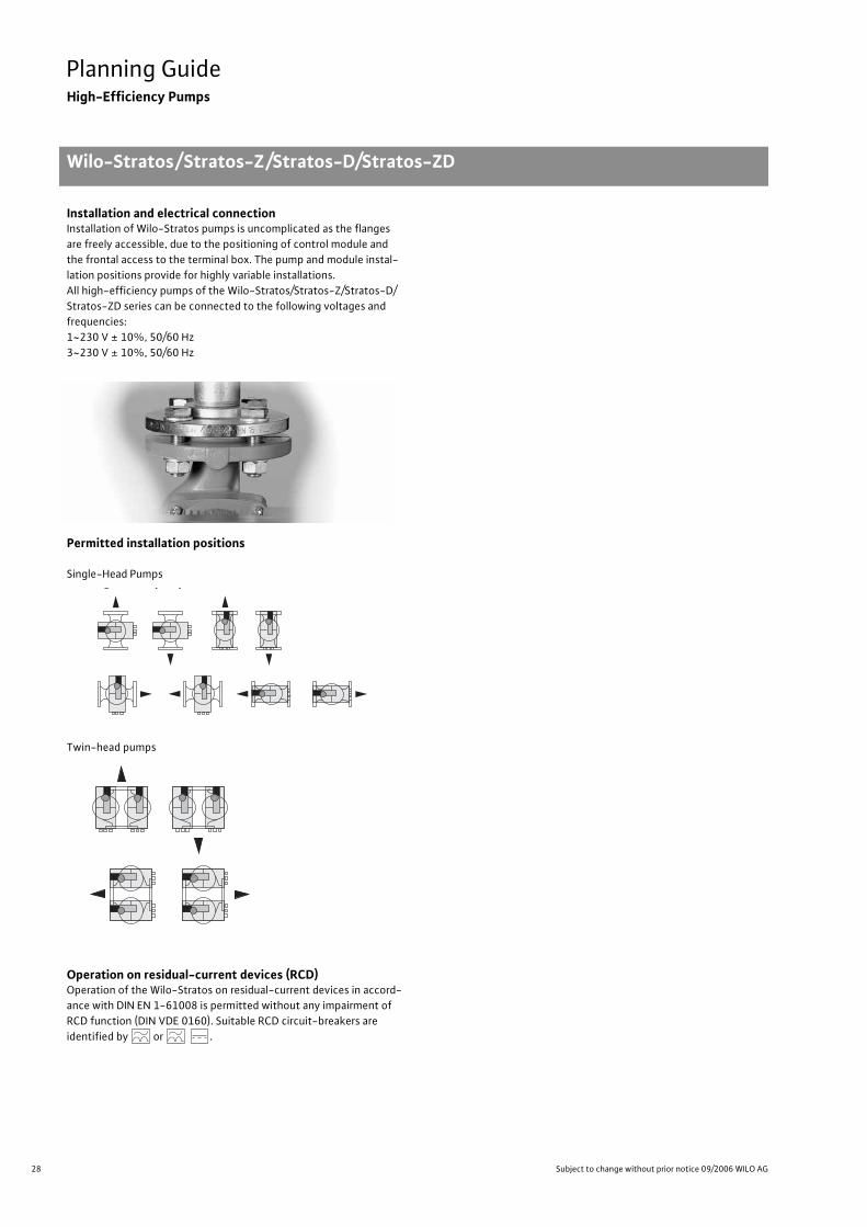
28 Subject to change without prior notice 09/2006 WILO AG
Planning GuideHigh-Efficiency Pumps
Wilo-Stratos/Stratos-Z/Stratos-D/Stratos-ZD
Installation and electrical connectionInstallation of Wilo-Stratos pumps is uncomplicated as the flanges
are freely accessible, due to the positioning of control module and
the frontal access to the terminal box. The pump and module instal-
lation positions provide for highly variable installations.
All high-efficiency pumps of the Wilo-Stratos/Stratos-Z/Stratos-D/
Stratos-ZD series can be connected to the following voltages and
frequencies:
1~230 V ± 10%, 50/60 Hz
3~230 V ± 10%, 50/60 Hz
Permitted installation positions
Single-Head Pumps
Twin-head pumps
Operation on residual-current devices (RCD)Operation of the Wilo-Stratos on residual-current devices in accord-
ance with DIN EN 1-61008 is permitted without any impairment of
RCD function (DIN VDE 0160). Suitable RCD circuit-breakers are
identified by or .
g p p
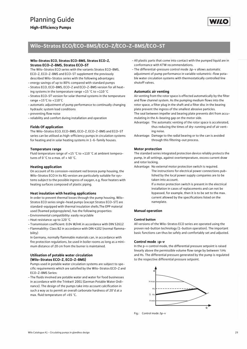
29
Planning GuideHigh-Efficiency Pumps
Wilo-Stratos ECO/ECO-BMS/ECO-Z/ECO-Z-BMS/ECO-ST
Wilo Catalogue A1 - Circulating pumps in glandless design
Hea
tin
g, A
ir-c
on
dit
ion
ing
, C
oo
ling
Po
tab
le w
ater
cir
cula
tio
nSo
lar
ther
mal
Serv
ice/
Acc
esso
ries
, Sys
tem
sSw
itch
gea
rs a
nd
Co
ntr
ol
Dev
ices
P
um
p M
anag
emen
t S y
stem
s
Wilo-Stratos ECO, Stratos ECO-BMS, Stratos ECO-Z, Stratos ECO-Z-BMS, Stratos ECO-STThe Wilo-Stratos ECO series with the variants Stratos ECO-BMS,
ECO-Z, ECO-Z-BMS and ECO-ST supplement the previously
described Wilo-Stratos series with the following advantages:
- energy savings of up to 80% compared with standard pumps
- Stratos ECO, ECO-BMS, ECO-Z and ECO-Z-BMS version for all heat-
ing systems in the temperature range +15 °C to +110 °C
- Stratos ECO-ST version for solar thermal systems in the temperature
range +15°C to +110°C
- automatic adjustment of pump performance to continually changing
hydraulic system load conditions
- preventing flow noise
- reliability and comfort during installation and operation
Fields Of applicationThe Wilo-Stratos ECO, ECO-BMS, ECO-Z, ECO-Z-BMS and ECO-ST
series can be utilised as high-efficiency pumps in circulation systems
for heating and in solar heating systems in 1-6-family houses.
Temperature rangeFluid temperature range of +15 °C to +110 °C at ambient tempera-
tures of 0 °C to a max. of + 40 °C.
Heating applicationOn account of its corrosion-resistant red bronze pump housing, the
Wilo-Stratos ECO in its RG version are particularly suitable for sys-
tems subject to the possible ingress of oxygen, e.g. floor heaters with
heating surfaces composed of plastic piping.
Heat insulation with heating applicationsIn order to prevent thermal losses through the pump housing, Wilo-
Stratos ECO series single-head pumps (except Stratos ECO-ST) are
standard-equipped with thermal insulation shells.The EPP material
used (foamed polypropylene), has the following properties:
- Environmental compatibility: easily recyclable
- Heat resistance: up to 120 °C
- Transmission coefficient: 0.04 W/mK in accordance with DIN 52612
- Flammability: Class B2 in accordance with DIN 4102 (normal flamma-
bility)
In Germany, normally flammable materials can, in accordance with
fire protection regulations, be used in boiler rooms as long as a mini-
mum distance of 20 cm from the burner is maintained.
Utilisation of potable water circulation(Wilo-Stratos ECO-Z, ECO-Z-BMS)Pumps used in potable water circulation systems are subject to spe-
cific requirements which are satisfied by the Wilo-Stratos ECO-Z and
ECO-Z-BMS Series:
- The fluids involved are potable water and water for food businesses
in accordance with the TrinkwV 2001 (German Potable Water Ordi-
nance). The design of the pumps take into account calcification in
such a way as to permit an overall carbonate hardness of 20°d at a
max. fluid temperature of +65 °C.
- All plastic parts that come into contact with the pumped liquid are in
conformance with KTW recommendations.
- The differential-pressure control mode p-v allows automatic
adjustment of pump performance in variable volumetric-flow pota-
ble water circulation systems with thermostatically controlled line
shutoff valves.
Automatic air ventingAir venting from the rotor space is effected automatically by the filter
and flow channel system. As the pumping medium flows into the
rotor space, a filter plug in the shaft and a filter disc in the bearing
plate prevent the ingress of the smallest abrasive particles.
The seal between impeller and bearing plate prevents dirt from accu-
mulating in the A-bearing gap on the motor side.
Advantage: The automatic venting of the rotor space is accelerated,
thus reducing the times of dry-running and of air vent-
ing noise.
Advantage: Damage to the radial bearing or to the can is avoided
through this filtering-out process.
Motor protectionThe standard series integrated protection device reliably protects the
pump, in all settings, against overtemperature, excess current draw
and rotor locking.
Advantage: No external motor protection switch is required.
The instructions for electrical power connections pub-
lished by the local power supply companies are to be
taken into account.
If a motor protection switch is present in the electrical
installation in cases of replacements and can not be
bypassed, for example, then it is to be set to the max.
current allowed by the specifications listed on the
nameplate.
Manual operation
Control buttonAll versions of the Wilo-Stratos ECO series are operated using the
proven red-button technology (1-button operation). The important
basic functions can thus be safely and comfortably set and adjusted.
Control mode p-vIn the p-v control mode, the differential pressure setpoint is raised
linearly above the permissible volume flow range by between ½Hs
and Hs. The differential pressure generated by the pump is regulated
to the respective differential pressure setpoint.
Fig.: Control mode p-v
H max
H
H min
Hs
Q
Hs1/2
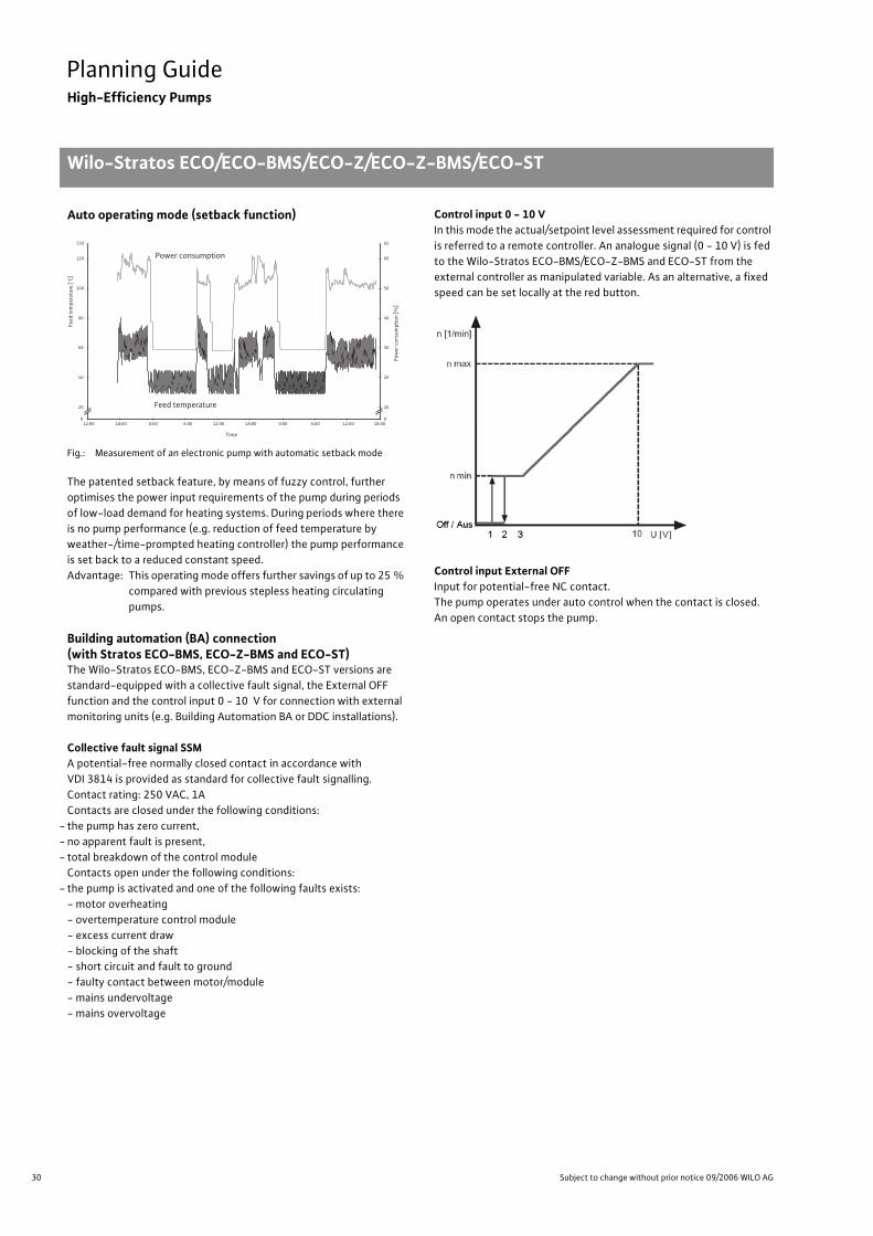
30 Subject to change without prior notice 09/2006 WILO AG
Planning GuideHigh-Efficiency Pumps
Wilo-Stratos ECO/ECO-BMS/ECO-Z/ECO-Z-BMS/ECO-ST
Auto operating mode (setback function)
Fig.: Measurement of an electronic pump with automatic setback mode
The patented setback feature, by means of fuzzy control, further
optimises the power input requirements of the pump during periods
of low-load demand for heating systems. During periods where there
is no pump performance (e.g. reduction of feed temperature by
weather-/time-prompted heating controller) the pump performance
is set back to a reduced constant speed.
Advantage: This operating mode offers further savings of up to 25 %
compared with previous stepless heating circulating
pumps.
Building automation (BA) connection(with Stratos ECO-BMS, ECO-Z-BMS and ECO-ST)The Wilo-Stratos ECO-BMS, ECO-Z-BMS and ECO-ST versions are
standard-equipped with a collective fault signal, the External OFF
function and the control input 0 - 10 V for connection with external
monitoring units (e.g. Building Automation BA or DDC installations).
Collective fault signal SSMA potential-free normally closed contact in accordance with
VDI 3814 is provided as standard for collective fault signalling.
Contact rating: 250 VAC, 1A
Contacts are closed under the following conditions:
- the pump has zero current,
- no apparent fault is present,
- total breakdown of the control module
Contacts open under the following conditions:
- the pump is activated and one of the following faults exists:
- motor overheating
- overtemperature control module
- excess current draw
- blocking of the shaft
- short circuit and fault to ground
- faulty contact between motor/module
- mains undervoltage
- mains overvoltage
Control input 0 - 10 VIn this mode the actual/setpoint level assessment required for control
is referred to a remote controller. An analogue signal (0 - 10 V) is fed
to the Wilo-Stratos ECO-BMS/ECO-Z-BMS and ECO-ST from the
external controller as manipulated variable. As an alternative, a fixed
speed can be set locally at the red button.
Control input External OFFInput for potential-free NC contact.
The pump operates under auto control when the contact is closed.
An open contact stops the pump.
Pow
er c
onsu
mpt
ion
[%]
0
20
40
60
80
100
120
130
12:00 18:00 0:00 6:00 12:00 18:00 0:00 6:00 12:00 18:00
Time
0
10
20
30
40
50
60
65
Power consumption
Feed temperature
Feed
tem
pera
ture
[°C
]
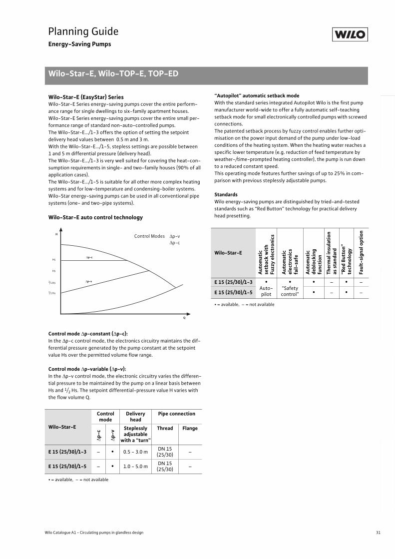
31
Planning GuideEnergy-Saving Pumps
Wilo-Star-E, Wilo-TOP-E, TOP-ED
Wilo Catalogue A1 - Circulating pumps in glandless design
Hea
tin
g, A
ir-c
on
dit
ion
ing
, C
oo
ling
Po
tab
le w
ater
cir
cula
tio
nSo
lar
ther
mal
Serv
ice/
Acc
esso
ries
, Sys
tem
sSw
itch
gea
rs a
nd
Co
ntr
ol
Dev
ices
P
um
p M
anag
emen
t S y
stem
s
Wilo-Star-E (EasyStar) SeriesWilo-Star-E Series energy-saving pumps cover the entire perform-
ance range for single dwellings to six-family apartment houses.
Wilo-Star-E Series energy-saving pumps cover the entire small per-
formance range of standard non-auto-controlled pumps.
The Wilo-Star-E.../1-3 offers the option of setting the setpoint
delivery head values between 0.5 m and 3 m.
With the Wilo-Star-E.../1-5, stepless settings are possible between
1 and 5 m differential pressure (delivery head).
The Wilo-Star-E.../1-3 is very well suited for covering the heat-con-
sumption requirements in single- and two-family houses (90% of all
application cases).
The Wilo-Star-E.../1-5 is suitable for all other more complex heating
systems and for low-temperature and condensing-boiler systems.
Wilo-Star energy-saving pumps can be used in all conventional pipe
systems (one- and two-pipe systems).
Wilo-Star-E auto control technology
Control mode p-constant ( p-c):In the p-c control mode, the electronics circuitry maintains the dif-
ferential pressure generated by the pump constant at the setpoint
value Hs over the permitted volume flow range.
Control mode p-variable ( p-v):In the p-v control mode, the electronic circuitry varies the differen-
tial pressure to be maintained by the pump on a linear basis between
Hs and 1/2 Hs. The setpoint differential-pressure value H varies with
the flow volume Q.
“Autopilot” automatic setback modeWith the standard series integrated Autopilot Wilo is the first pump
manufacturer world-wide to offer a fully automatic self-teaching
setback mode for small electronically controlled pumps with screwed
connections.
The patented setback process by fuzzy control enables further opti-
misation on the power input demand of the pump under low-load
conditions of the heating system. When the heating water reaches a
specific lower temperature (e.g. reduction of feed temperature by
weather-/time-prompted heating controller), the pump is run down
to a reduced constant speed.
This operating mode features further savings of up to 25% in com-
parison with previous steplessly adjustable pumps.
StandardsWilo energy-saving pumps are distinguished by tried-and-tested
standards such as “Red Button” technology for practical delivery
head presetting.
Wilo-Star-E
Control mode
Deliveryhead
Pipe connection
p-c
p-v
Steplessly adjustable
with a “turn”
Thread Flange
E 15 (25/30)/1-3 – • 0.5 - 3.0 mDN 15
(25/30)–
E 15 (25/30)/1-5 – • 1.0 - 5.0 mDN 15
(25/30)–
• = available, – = not available
Hs
Q
Hs
/ Hs1 2
/ Hs3 4
p-c
p-v
Control ModesH
Wilo-Star-EA
uto
mat
icse
tbac
k w
ith
Fuzz
y el
ectr
on
ics
Au
tom
atic
elec
tro
nic
sfa
il-sa
fe
Au
tom
atic
deb
lock
ing
fun
ctio
n
Th
erm
al in
sula
tio
n
as s
tan
dar
d
“Red
Bu
tto
n”
tech
no
log
y
Fau
lt-s
ign
al o
pti
on
E 15 (25/30)/1-3 •Auto-pilot
•“Safety control”
• – • –
E 15 (25/30)/1-5 • – • –
• = available, – = not available
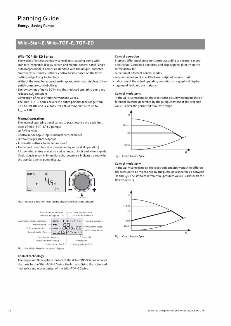
32 Subject to change without prior notice 09/2006 WILO AG
Planning GuideEnergy-Saving Pumps
Wilo-Star-E, Wilo-TOP-E, TOP-ED
Wilo-TOP-E/-ED SeriesThe world’s first electronically controlled circulating pump with
standard integrated display screen and manual control panel (single
button operation). It comes as standard with the unique, patented
“Autopilot” automatic setback control facility based on the latest
cutting-edge Fuzzy technology.
Without the need for external switchgears, automatic stepless differ-
ential-pressure control offers:
- Energy savings of up to 50 % and thus reduced operating costs and
reduced CO2 emissions
- Elimination of noises from thermostatic valves.
The Wilo-TOP-E Series covers the entire performance range from
Rp 1 to DN 100 and is suitable for a fluid temperature of up to
Tmax = 110 °C.
Manual operationThe manual operating panel serves to parameterise the basic func-
tions of Wilo-TOP-E/-ED pumps:
- On/Off control
- Control mode ( p-c, p-v, manual control mode)
- Differential pressure setpoint
- Automatic setback to minimum speed
- Twin-head pump function (main/standby or parallel operation)
All operating states as well as a wide range of fault and alarm signals
(fault signals result in immediate shutdown) are indicated directly in
the standard series pump display.
Fig.: Manual operation level (pump display and operating button)
Fig.: Symbols featured in pump display
Control technologyThe single and three-phase motors of the Wilo-TOP-S Series serve as
the basis for the Wilo-TOP-E Series, the latter utilising the optimised
hydraulics and motor design of the Wilo-TOP-S Series.
Control operationStepless differential pressure control according to the pre-set set-
point value. Combined operating and display panel directly on the
terminal box for:
- selection of different control modes
- setpoint adjustment in m (the lower setpoint value is 1 m)
- indication of the actual operating condition on a graphical display
- logging of fault and alarm signals.
Control mode p-cIn the p-c control mode, the electronics circuitry maintains the dif-
ferential pressure generated by the pump constant at the setpoint
value Hs over the permitted flow-rate range.
Fig.: Control mode p-c
Control mode p-vIn the p-v control mode, the electronic circuitry varies the differen-
tial pressure to be maintained by the pump on a linear basis between
Hs and 1 2s. The setpoint differential-pressure value H varies with the
flow volume Q.
Fig.: Control mode p-v
H m
auto
on
Automatic setback operation
GLT communication HRPM
m x100
auto + /
on off
Keyboard lock
Control mode Dp-c
Control mode Dp-v
Control mode (n-const.)
Control mode Dp-T Analog input 0-10 V
Pump On
Pump Off
Parallel operation
Standby operation
Unit, delivery head
Unit, motor speed
Pump at min. speed
Pump under auto control Current set point level
10V
Q
H max
Hs
H min
H
Q
H max
Hs
H min
½Hs
H
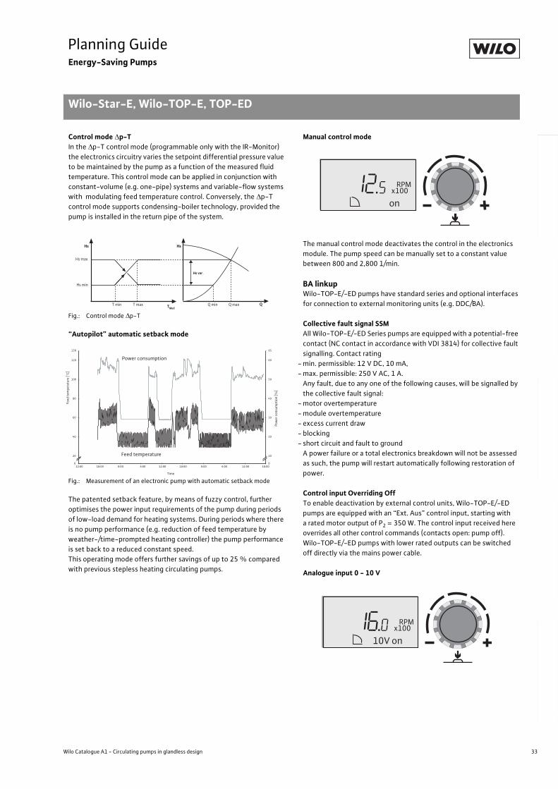
33
Planning GuideEnergy-Saving Pumps
Wilo-Star-E, Wilo-TOP-E, TOP-ED
Wilo Catalogue A1 - Circulating pumps in glandless design
Hea
tin
g, A
ir-c
on
dit
ion
ing
, C
oo
ling
Po
tab
le w
ater
cir
cula
tio
nSo
lar
ther
mal
Serv
ice/
Acc
esso
ries
, Sys
tem
sSw
itch
gea
rs a
nd
Co
ntr
ol
Dev
ices
P
um
p M
anag
emen
t S y
stem
s
Control mode p-TIn the p-T control mode (programmable only with the IR-Monitor)
the electronics circuitry varies the setpoint differential pressure value
to be maintained by the pump as a function of the measured fluid
temperature. This control mode can be applied in conjunction with
constant-volume (e.g. one-pipe) systems and variable-flow systems
with modulating feed temperature control. Conversely, the p-T
control mode supports condensing-boiler technology, provided the
pump is installed in the return pipe of the system.
Fig.: Control mode p-T
“Autopilot” automatic setback mode
Fig.: Measurement of an electronic pump with automatic setback mode
The patented setback feature, by means of fuzzy control, further
optimises the power input requirements of the pump during periods
of low-load demand for heating systems. During periods where there
is no pump performance (e.g. reduction of feed temperature by
weather-/time-prompted heating controller) the pump performance
is set back to a reduced constant speed.
This operating mode offers further savings of up to 25 % compared
with previous stepless heating circulating pumps.
Manual control mode
The manual control mode deactivates the control in the electronics
module. The pump speed can be manually set to a constant value
between 800 and 2,800 1/min.
BA linkupWilo-TOP-E/-ED pumps have standard series and optional interfaces
for connection to external monitoring units (e.g. DDC/BA).
Collective fault signal SSMAll Wilo-TOP-E/-ED Series pumps are equipped with a potential-free
contact (NC contact in accordance with VDI 3814) for collective fault
signalling. Contact rating
- min. permissible: 12 V DC, 10 mA,
- max. permissible: 250 V AC, 1 A.
Any fault, due to any one of the following causes, will be signalled by
the collective fault signal:
- motor overtemperature
- module overtemperature
- excess current draw
- blocking
- short circuit and fault to ground
A power failure or a total electronics breakdown will not be assessed
as such, the pump will restart automatically following restoration of
power.
Control input Overriding OffTo enable deactivation by external control units, Wilo-TOP-E/-ED
pumps are equipped with an “Ext. Aus” control input, starting with
a rated motor output of P2 = 350 W. The control input received here
overrides all other control commands (contacts open: pump off).
Wilo-TOP-E/-ED pumps with lower rated outputs can be switched
off directly via the mains power cable.
Analogue input 0 - 10 V
Hs max
Q
Hs min
T min T max Q min Q max
Hs var .
Hs Hs
TMed
Pow
er c
onsu
mpt
ion
[%]
0
20
40
60
80
100
120
130
12:00 18:00 0:00 6:00 12:00 18:00 0:00 6:00 12:00 18:00
Time
0
10
20
30
40
50
60
65
Power consumption
Feed temperature
Feed
tem
pera
ture
[°C
]
RPM x100
on
RPM x100
on 10V
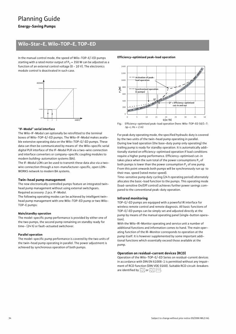
34 Subject to change without prior notice 09/2006 WILO AG
Planning GuideEnergy-Saving Pumps
Wilo-Star-E, Wilo-TOP-E, TOP-ED
In the manual control mode, the speed of Wilo-TOP-E/-ED pumps
starting with a rated motor output of P2 = 350 W can be adjusted as a
function of an external control voltage (0 - 10 V). The electronics
module control is deactivated in such case.
“IF-Modul” serial interfaceThe Wilo-IF-Modul can optionally be retrofitted to the terminal
boxes of Wilo-TOP-E/-ED pumps. The Wilo-IF-Modul makes availa-
ble extensive operating data on the Wilo-TOP-E/-ED pumps. These
data can then be communicated by means of the Wilo-specific serial
digital PLR interface of the IF-Modul PLR via a two-wire connection
and interface converters or company-specific coupling modules to
modern building-automation systems (BA).
The IF-Modul LON can be used to transmit these data also via a two-
wire connection through a non-manufacturer-specific, open LON-
WORKS network to modern BA systems.
Twin-head pump managementThe new electronically controlled pumps feature an integrated twin-
head pump management without using external switchgears.
Required accessory: 2 pcs. IF-Modul.
The following operating modes can be achieved by intelligent twin-
head pump management with one Wilo-TOP-ED pump or two Wilo-
TOP-E pumps:
Main/standby operationThe model-specific pump performance is provided by either one of
the two pumps, the second pump remaining on standby ready for
time- (24 h) or fault-actuated switchover.
Parallel operationThe model-specific pump performance is covered by the two units of
the twin-head pump operating in parallel. The power adjustment is
achieved by synchronous operation of both pumps.
Efficiency-optimised peak-load operation
Fig.: Efficiency-optimised peak-load operation (here: Wilo-TOP-ED 50/1-7; p-c; Hs = 2 m)
For peak duty operating mode, the specified hydraulic duty is covered
by the two units of the twin-head pump operating in parallel.
During low load operation (the base-duty pump only operating) the
trailing pump is ready for standby operation. It is automatically addi-
tionally started on efficiency-optimised operation if load conditions
require a higher pump performance. Efficiency-optimised cut-in
takes place when the sum total of the power consumptions P1 of
both pumps is lower than the power consumption P1 of one pump.
From this point onwards both pumps will be synchronously run up to
their max. speed (rated motor speed).
Time-sensitive pump duty cycling (24 h operating period) alternately
allocates the basic-load function to the pumps. This operating mode
(load-sensitive On/Off control) achieves further power savings com-
pared to the conventional peak-duty operation.
Infrared monitoringTOP-E/-ED pumps are equipped with a powerful IR interface for
wireless remote control and remote diagnosis. All basic functions of
TOP-E/-ED pumps can be simply set and adjusted directly at the
pump by means of the manual operating panel (single-button opera-
tion).
With the Wilo-IR-Monitor operating and service unit a number of
additional functions and information comes to hand. The main oper-
ating function of the IR-Monitor corresponds to operation at the
pump itself. It is however supplemented by some important addi-
tional functions which essentially exceed those available at the
pump.
Operation on residual-current devices (RCD)Operation of the Wilo-TOP-E/-ED Series on residual-current devices
in accordance with DIN EN 61008-1 is permitted without any impair-
ment of RCD function (DIN VDE 0160). Suitable RCD circuit-breakers
are identified by or .
n[1/mín]
n max
n min
Off10U[V]1 32
0
200
400
600
800
1000
1200
1400
0 5 10 15 20 25 30 35 40
Q [m 3/h]P
1[W
]
Activation of peak-load operation
Q*
Synchronised operation (2 pumps)
Q* = Efficiency-optimised cut-in and out
35
Planning GuideEnergy-Saving Pumps
Wilo Catalogue A1 - Circulating pumps in glandless design
Hea
tin
g, A
ir-c
on
dit
ion
ing
, C
oo
ling
Po
tab
le w
ater
cir
cula
tio
nSo
lar
ther
mal
Serv
ice/
Acc
esso
ries
, Sys
tem
sSw
itch
gea
rs a
nd
Co
ntr
ol
Dev
ices
P
um
p M
anag
emen
t S y
stem
s
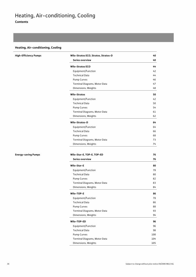
36 Subject to change without prior notice 09/2006 WILO AG
Heating, Air-conditioning, CoolingContents
Heating, Air-conditioning, Cooling
High-Efficiency Pumps Wilo-Stratos ECO, Stratos, Stratos-D 40
Series overview 40
Wilo-Stratos ECO 44
Equipment/Function 42
Technical Data 44
Pump Curves 46
Terminal Diagrams, Motor Data 47
Dimensions, Weights 48
Wilo-Stratos 50
Equipment/Function 42
Technical Data 50
Pump Curves 54
Terminal Diagrams, Motor Data 61
Dimensions, Weights 62
Wilo-Stratos-D 64
Equipment/Function 64
Technical Data 66
Pump Curves 68
Terminal Diagrams, Motor Data 73
Dimensions, Weights 74
Energy-saving Pumps Wilo-Star-E, TOP-E, TOP-ED 76
Series overview 76
Wilo-Star-E 80
Equipment/Function 78
Technical Data 80
Pump Curves 82
Terminal Diagrams, Motor Data 83
Dimensions, Weights 84
Wilo-TOP-E 86
Equipment/Function 78
Technical Data 86
Pump Curves 88
Terminal Diagrams, Motor Data 93
Dimensions, Weights 94
Wilo-TOP-ED 96
Equipment/Function 96
Technical Data 98
Pump Curves 100
Terminal Diagrams, Motor Data 104
Dimensions, Weights 105
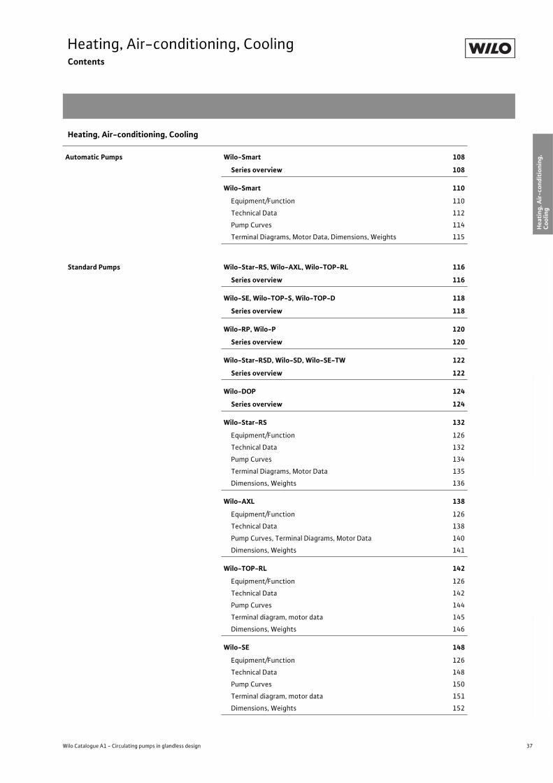
37
Heating, Air-conditioning, CoolingContents
Wilo Catalogue A1 - Circulating pumps in glandless design
Hea
tin
g, A
ir-c
on
dit
ion
ing
, C
oo
ling
Po
tab
le w
ater
cir
cula
tio
nSo
lar
ther
mal
Serv
ice/
Acc
esso
ries
, Sys
tem
sSw
itch
gea
rs a
nd
Co
ntr
ol
Dev
ices
P
um
p M
anag
emen
t S y
stem
s
Automatic Pumps Wilo-Smart 108
Series overview 108
Wilo-Smart 110
Equipment/Function 110
Technical Data 112
Pump Curves 114
Terminal Diagrams, Motor Data, Dimensions, Weights 115
Standard Pumps Wilo-Star-RS, Wilo-AXL, Wilo-TOP-RL 116
Series overview 116
Wilo-SE, Wilo-TOP-S, Wilo-TOP-D 118
Series overview 118
Wilo-RP, Wilo-P 120
Series overview 120
Wilo-Star-RSD, Wilo-SD, Wilo-SE-TW 122
Series overview 122
Wilo-DOP 124
Series overview 124
Wilo-Star-RS 132
Equipment/Function 126
Technical Data 132
Pump Curves 134
Terminal Diagrams, Motor Data 135
Dimensions, Weights 136
Wilo-AXL 138
Equipment/Function 126
Technical Data 138
Pump Curves, Terminal Diagrams, Motor Data 140
Dimensions, Weights 141
Wilo-TOP-RL 142
Equipment/Function 126
Technical Data 142
Pump Curves 144
Terminal diagram, motor data 145
Dimensions, Weights 146
Wilo-SE 148
Equipment/Function 126
Technical Data 148
Pump Curves 150
Terminal diagram, motor data 151
Dimensions, Weights 152
Heating, Air-conditioning, Cooling
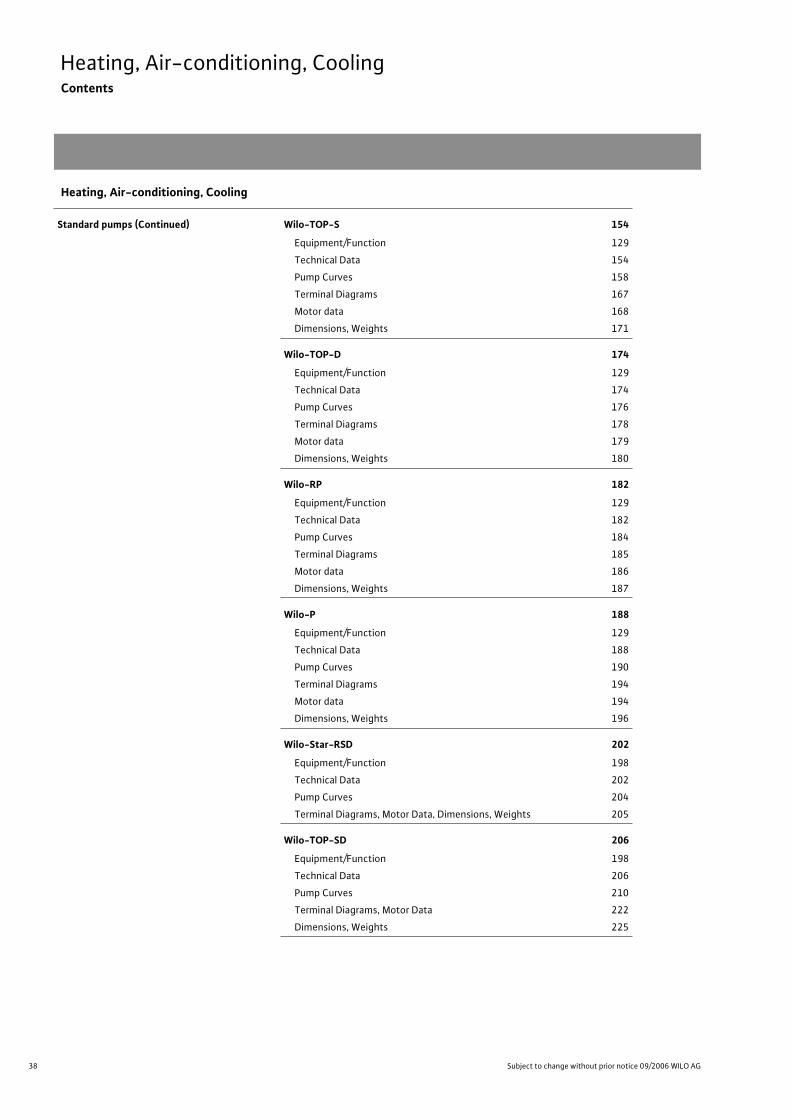
38 Subject to change without prior notice 09/2006 WILO AG
Heating, Air-conditioning, CoolingContents
Standard pumps (Continued) Wilo-TOP-S 154
Equipment/Function 129
Technical Data 154
Pump Curves 158
Terminal Diagrams 167
Motor data 168
Dimensions, Weights 171
Wilo-TOP-D 174
Equipment/Function 129
Technical Data 174
Pump Curves 176
Terminal Diagrams 178
Motor data 179
Dimensions, Weights 180
Wilo-RP 182
Equipment/Function 129
Technical Data 182
Pump Curves 184
Terminal Diagrams 185
Motor data 186
Dimensions, Weights 187
Wilo-P 188
Equipment/Function 129
Technical Data 188
Pump Curves 190
Terminal Diagrams 194
Motor data 194
Dimensions, Weights 196
Wilo-Star-RSD 202
Equipment/Function 198
Technical Data 202
Pump Curves 204
Terminal Diagrams, Motor Data, Dimensions, Weights 205
Wilo-TOP-SD 206
Equipment/Function 198
Technical Data 206
Pump Curves 210
Terminal Diagrams, Motor Data 222
Dimensions, Weights 225
Heating, Air-conditioning, Cooling
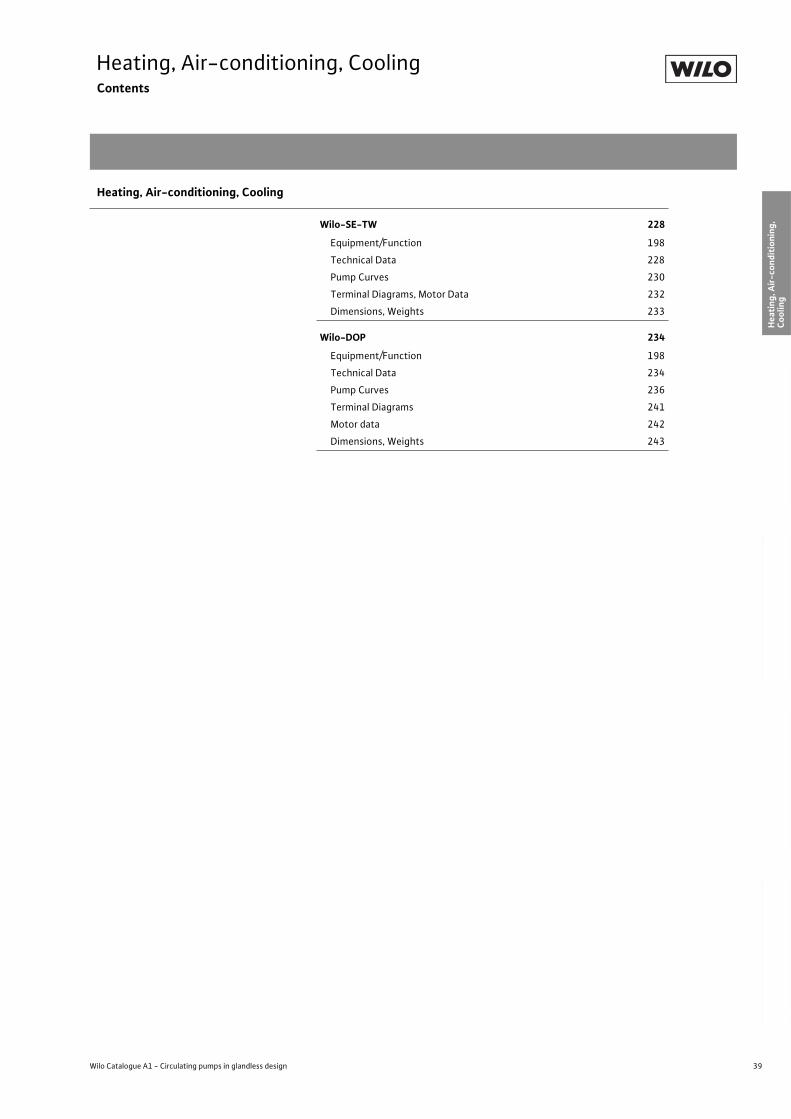
39
Heating, Air-conditioning, CoolingContents
Wilo Catalogue A1 - Circulating pumps in glandless design
Hea
tin
g, A
ir-c
on
dit
ion
ing
, C
oo
ling
Po
tab
le w
ater
cir
cula
tio
nSo
lar
ther
mal
Serv
ice/
Acc
esso
ries
, Sys
tem
sSw
itch
gea
rs a
nd
Co
ntr
ol
Dev
ices
P
um
p M
anag
emen
t S y
stem
s
Wilo-SE-TW 228
Equipment/Function 198
Technical Data 228
Pump Curves 230
Terminal Diagrams, Motor Data 232
Dimensions, Weights 233
Wilo-DOP 234
Equipment/Function 198
Technical Data 234
Pump Curves 236
Terminal Diagrams 241
Motor data 242
Dimensions, Weights 243
Heating, Air-conditioning, Cooling
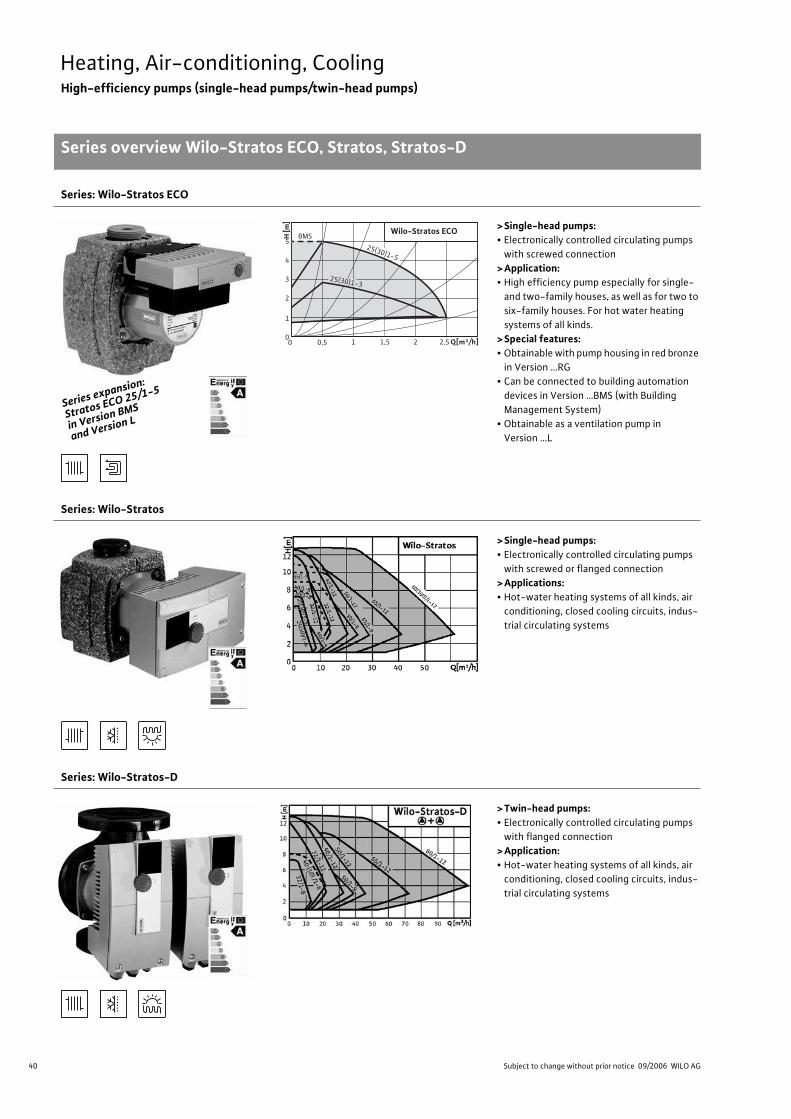
40 Subject to change without prior notice 09/2006 WILO AG
Heating, Air-conditioning, CoolingHigh-efficiency pumps (single-head pumps/twin-head pumps)
Series overview Wilo-Stratos ECO, Stratos, Stratos-D
Series: Wilo-Stratos ECO
> Single-head pumps:• Electronically controlled circulating pumps
with screwed connection
> Application:• High efficiency pump especially for single-
and two-family houses, as well as for two to
six-family houses. For hot water heating
systems of all kinds.
> Special features:• Obtainable with pump housing in red bronze
in Version …RG
• Can be connected to building automation
devices in Version …BMS (with Building
Management System)
• Obtainable as a ventilation pump in
Version …L
Series: Wilo-Stratos
> Single-head pumps:• Electronically controlled circulating pumps
with screwed or flanged connection
> Applications: • Hot-water heating systems of all kinds, air
conditioning, closed cooling circuits, indus-
trial circulating systems
Series: Wilo-Stratos-D
> Twin-head pumps:• Electronically controlled circulating pumps
with flanged connection
> Application:• Hot-water heating systems of all kinds, air
conditioning, closed cooling circuits, indus-
trial circulating systems
Series exp
ansion:
Stratos EC
O 25/1-5
in Version
BMS
and Versio
n L
H [m
]
5
4
3
2
1
0 Q[m³/h]1,5 1 2,5 2 0 0,5
25(30)1-3
25(30)1-5
Wilo-Stratos ECO BMS
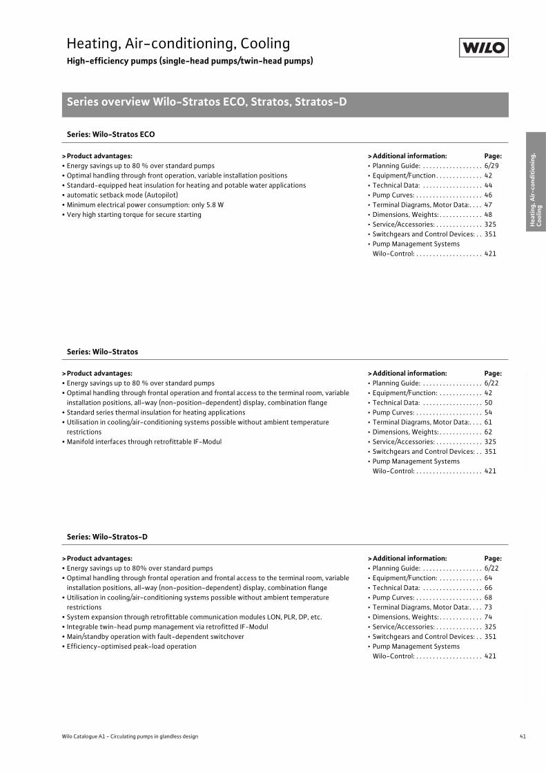
41
Heating, Air-conditioning, CoolingHigh-efficiency pumps (single-head pumps/twin-head pumps)
Series overview Wilo-Stratos ECO, Stratos, Stratos-D
Wilo Catalogue A1 - Circulating pumps in glandless design
Hea
tin
g, A
ir-c
on
dit
ion
ing
, C
oo
ling
Po
tab
le w
ater
cir
cula
tio
nSo
lar
ther
mal
Serv
ice/
Acc
esso
ries
, Sys
tem
sSw
itch
gea
rs a
nd
Co
ntr
ol
Dev
ices
P
um
p M
anag
emen
t S y
stem
s
Series: Wilo-Stratos ECO
> Product advantages:• Energy savings up to 80 % over standard pumps
• Optimal handling through front operation, variable installation positions
• Standard-equipped heat insulation for heating and potable water applications
• automatic setback mode (Autopilot)
• Minimum electrical power consumption: only 5.8 W
• Very high starting torque for secure starting
>Additional information: Page:• Planning Guide: . . . . . . . . . . . . . . . . . . 6/29
• Equipment/Function . . . . . . . . . . . . . . 42
• Technical Data: . . . . . . . . . . . . . . . . . . 44
• Pump Curves: . . . . . . . . . . . . . . . . . . . . 46
• Terminal Diagrams, Motor Data:. . . . 47
• Dimensions, Weights: . . . . . . . . . . . . . 48
• Service/Accessories: . . . . . . . . . . . . . . 325
• Switchgears and Control Devices: . . 351
• Pump Management Systems
Wilo-Control: . . . . . . . . . . . . . . . . . . . . 421
Series: Wilo-Stratos
> Product advantages:• Energy savings up to 80 % over standard pumps
• Optimal handling through frontal operation and frontal access to the terminal room, variable
installation positions, all-way (non-position-dependent) display, combination flange
• Standard series thermal insulation for heating applications
• Utilisation in cooling/air-conditioning systems possible without ambient temperature
restrictions
• Manifold interfaces through retrofittable IF-Modul
>Additional information: Page:• Planning Guide: . . . . . . . . . . . . . . . . . . 6/22
• Equipment/Function: . . . . . . . . . . . . . 42
• Technical Data: . . . . . . . . . . . . . . . . . . 50
• Pump Curves: . . . . . . . . . . . . . . . . . . . . 54
• Terminal Diagrams, Motor Data:. . . . 61
• Dimensions, Weights: . . . . . . . . . . . . . 62
• Service/Accessories: . . . . . . . . . . . . . . 325
• Switchgears and Control Devices: . . 351
• Pump Management Systems
Wilo-Control: . . . . . . . . . . . . . . . . . . . . 421
Series: Wilo-Stratos-D
> Product advantages:• Energy savings up to 80% over standard pumps
• Optimal handling through frontal operation and frontal access to the terminal room, variable
installation positions, all-way (non-position-dependent) display, combination flange
• Utilisation in cooling/air-conditioning systems possible without ambient temperature
restrictions
• System expansion through retrofittable communication modules LON, PLR, DP, etc.
• Integrable twin-head pump management via retrofitted IF-Modul
• Main/standby operation with fault-dependent switchover
• Efficiency-optimised peak-load operation
>Additional information: Page:• Planning Guide: . . . . . . . . . . . . . . . . . . 6/22
• Equipment/Function: . . . . . . . . . . . . . 64
• Technical Data: . . . . . . . . . . . . . . . . . . 66
• Pump Curves: . . . . . . . . . . . . . . . . . . . . 68
• Terminal Diagrams, Motor Data:. . . . 73
• Dimensions, Weights: . . . . . . . . . . . . . 74
• Service/Accessories: . . . . . . . . . . . . . . 325
• Switchgears and Control Devices: . . 351
• Pump Management Systems
Wilo-Control: . . . . . . . . . . . . . . . . . . . . 421
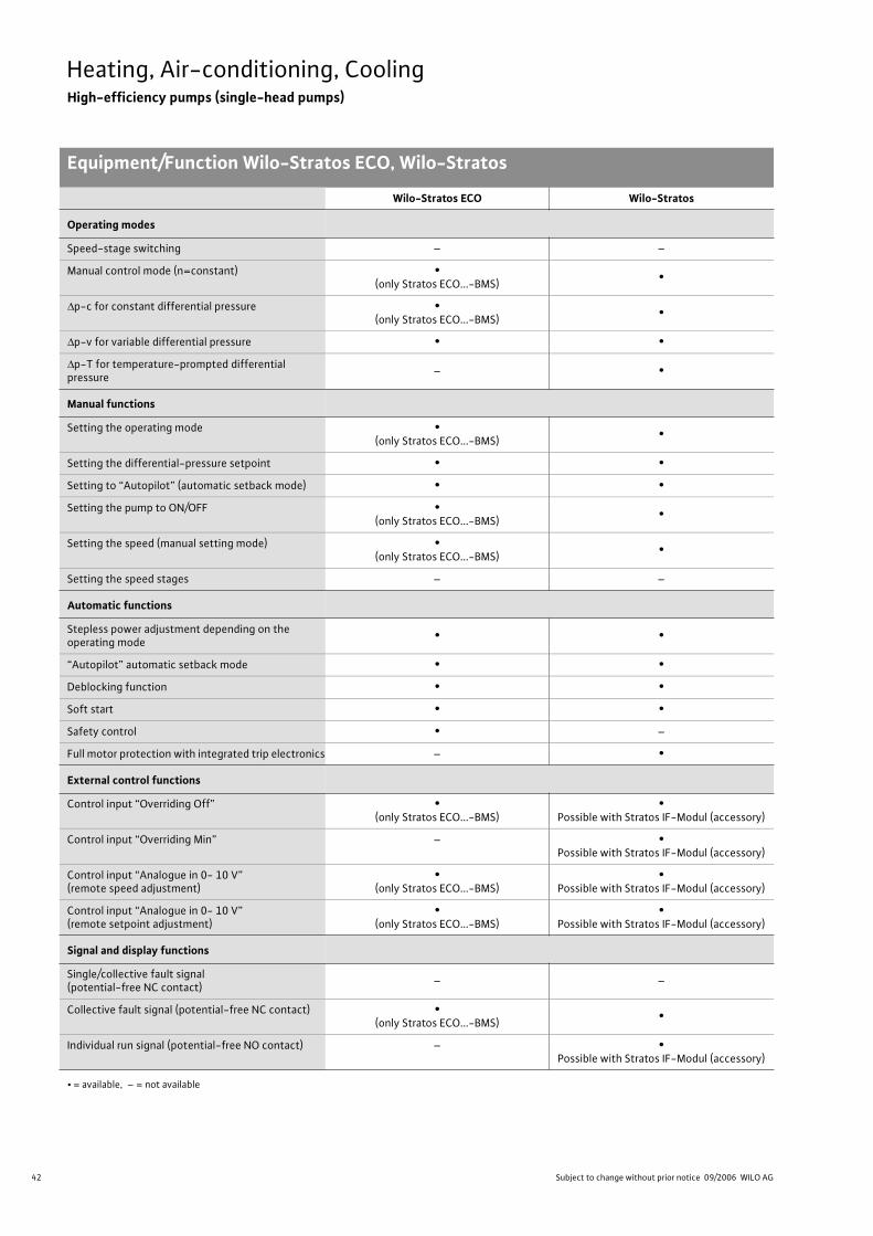
42 Subject to change without prior notice 09/2006 WILO AG
Heating, Air-conditioning, CoolingHigh-efficiency pumps (single-head pumps)
Equipment/Function Wilo-Stratos ECO, Wilo-Stratos
Wilo-Stratos ECO Wilo-Stratos
Operating modes
Speed-stage switching – –
Manual control mode (n=constant) •(only Stratos ECO...-BMS)
•
p-c for constant differential pressure •(only Stratos ECO...-BMS)
•
p-v for variable differential pressure • •
p-T for temperature-prompted differential pressure
– •
Manual functions
Setting the operating mode •(only Stratos ECO...-BMS)
•
Setting the differential-pressure setpoint • •
Setting to “Autopilot” (automatic setback mode) • •
Setting the pump to ON/OFF •(only Stratos ECO...-BMS)
•
Setting the speed (manual setting mode) •(only Stratos ECO...-BMS)
•
Setting the speed stages – –
Automatic functions
Stepless power adjustment depending on the operating mode
• •
“Autopilot” automatic setback mode • •
Deblocking function • •
Soft start • •
Safety control • –
Full motor protection with integrated trip electronics – •
External control functions
Control input “Overriding Off” •(only Stratos ECO...-BMS)
•Possible with Stratos IF-Modul (accessory)
Control input “Overriding Min” – •Possible with Stratos IF-Modul (accessory)
Control input “Analogue in 0- 10 V” (remote speed adjustment)
•(only Stratos ECO...-BMS)
•Possible with Stratos IF-Modul (accessory)
Control input “Analogue in 0- 10 V” (remote setpoint adjustment)
•(only Stratos ECO...-BMS)
•Possible with Stratos IF-Modul (accessory)
Signal and display functions
Single/collective fault signal (potential-free NC contact)
– –
Collective fault signal (potential-free NC contact) •(only Stratos ECO...-BMS)
•
Individual run signal (potential-free NO contact) – •Possible with Stratos IF-Modul (accessory)
• = available, – = not available
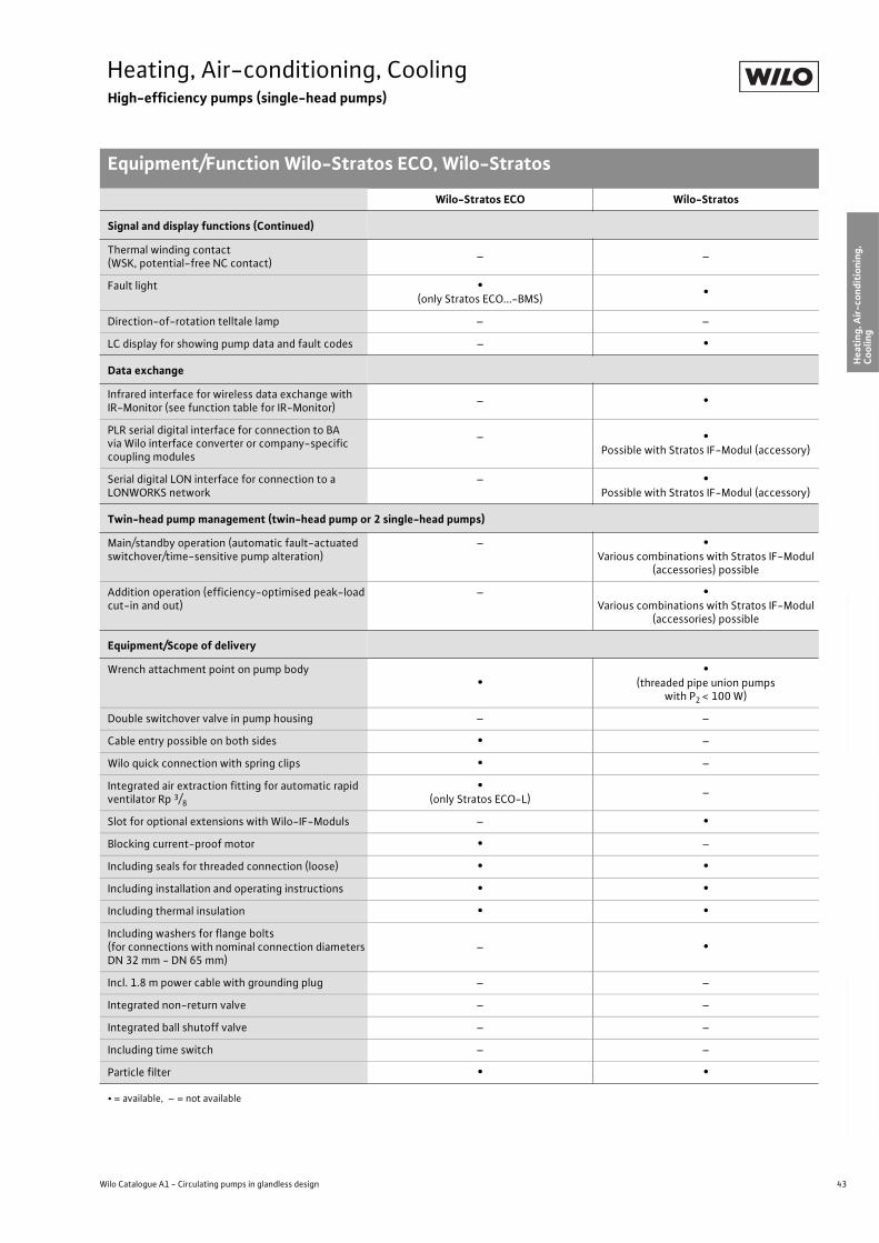
43
Heating, Air-conditioning, CoolingHigh-efficiency pumps (single-head pumps)
Equipment/Function Wilo-Stratos ECO, Wilo-Stratos
Wilo Catalogue A1 - Circulating pumps in glandless design
Hea
tin
g, A
ir-c
on
dit
ion
ing
, C
oo
ling
Po
tab
le w
ater
cir
cula
tio
nSo
lar
ther
mal
Serv
ice/
Acc
esso
ries
, Sys
tem
sSw
itch
gea
rs a
nd
Co
ntr
ol
Dev
ices
P
um
p M
anag
emen
t S y
stem
s
Signal and display functions (Continued)
Thermal winding contact (WSK, potential-free NC contact)
– –
Fault light •(only Stratos ECO...-BMS)
•
Direction-of-rotation telltale lamp – –
LC display for showing pump data and fault codes – •
Data exchange
Infrared interface for wireless data exchange with IR-Monitor (see function table for IR-Monitor)
– •
PLR serial digital interface for connection to BA via Wilo interface converter or company-specific coupling modules
– •Possible with Stratos IF-Modul (accessory)
Serial digital LON interface for connection to a LONWORKS network
– •Possible with Stratos IF-Modul (accessory)
Twin-head pump management (twin-head pump or 2 single-head pumps)
Main/standby operation (automatic fault-actuated switchover/time-sensitive pump alteration)
– •Various combinations with Stratos IF-Modul
(accessories) possible
Addition operation (efficiency-optimised peak-load cut-in and out)
– •Various combinations with Stratos IF-Modul
(accessories) possible
Equipment/Scope of delivery
Wrench attachment point on pump body•
•(threaded pipe union pumps
with P2 < 100 W)
Double switchover valve in pump housing – –
Cable entry possible on both sides • –
Wilo quick connection with spring clips • –
Integrated air extraction fitting for automatic rapid ventilator Rp 3/8
•(only Stratos ECO-L)
–
Slot for optional extensions with Wilo-IF-Moduls – •
Blocking current-proof motor • –
Including seals for threaded connection (loose) • •
Including installation and operating instructions • •
Including thermal insulation • •
Including washers for flange bolts (for connections with nominal connection diameters DN 32 mm - DN 65 mm)
– •
Incl. 1.8 m power cable with grounding plug – –
Integrated non-return valve – –
Integrated ball shutoff valve – –
Including time switch – –
Particle filter • •
Wilo-Stratos ECO Wilo-Stratos
• = available, – = not available
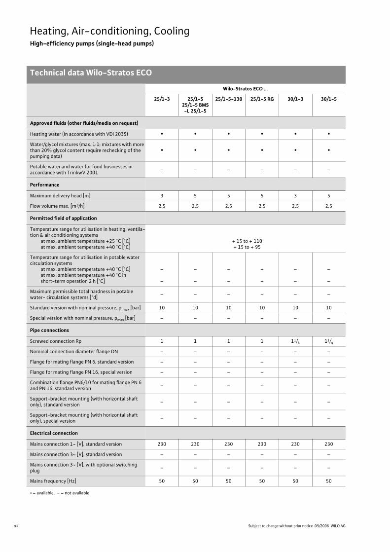
44 Subject to change without prior notice 09/2006 WILO AG
Heating, Air-conditioning, CoolingHigh-efficiency pumps (single-head pumps)
Technical data Wilo-Stratos ECO
Wilo-Stratos ECO ...
25/1-3 25/1-525/1-5 BMS-L 25/1-5
25/1-5-130 25/1-5 RG 30/1-3 30/1-5
Approved fluids (other fluids/media on request)
Heating water (In accordance with VDI 2035) • • • • • •
Water/glycol mixtures (max. 1:1; mixtures with more than 20% glycol content require rechecking of the pumping data)
• • • • • •
Potable water and water for food businesses in accordance with TrinkwV 2001
– – – – – –
Performance
Maximum delivery head [m] 3 5 5 5 3 5
Flow volume max. [m3/h] 2,5 2,5 2,5 2,5 2,5 2,5
Permitted field of application
Temperature range for utilisation in heating, ventila-tion & air conditioning systems
at max. ambient temperature +25 °C [°C]at max. ambient temperature +40 °C [°C]
+ 15 to + 110 + 15 to + 95
Temperature range for utilisation in potable water circulation systems
at max. ambient temperature +40 °C [°C]at max. ambient temperature +40 °C in short-term operation 2 h [°C]
–
–
–
–
–
–
–
–
–
–
–
–
Maximum permissible total hardness in potable water- circulation systems [°d]
– – – – – –
Standard version with nominal pressure, p max [bar] 10 10 10 10 10 10
Special version with nominal pressure, pmax [bar] – – – – – –
Pipe connections
Screwed connection Rp 1 1 1 1 11/4 11/4
Nominal connection diameter flange DN – – – – – –
Flange for mating flange PN 6, standard version – – – – – –
Flange for mating flange PN 16, special version – – – – – –
Combination flange PN6/10 for mating flange PN 6 and PN 16, standard version
– – – – – –
Support-bracket mounting (with horizontal shaft only), standard version
– – – – – –
Support-bracket mounting (with horizontal shaft only), special version
– – – – – –
Electrical connection
Mains connection 1~ [V], standard version 230 230 230 230 230 230
Mains connection 3~ [V], standard version – – – – – –
Mains connection 3~ [V], with optional switching plug
– – – – – –
Mains frequency [Hz] 50 50 50 50 50 50
• = available, – = not available

45
Heating, Air-conditioning, CoolingHigh-efficiency pumps (single-head pumps)
Technical data Wilo-Stratos ECO
Wilo Catalogue A1 - Circulating pumps in glandless design
Hea
tin
g, A
ir-c
on
dit
ion
ing
, C
oo
ling
Po
tab
le w
ater
cir
cula
tio
nSo
lar
ther
mal
Serv
ice/
Acc
esso
ries
, Sys
tem
sSw
itch
gea
rs a
nd
Co
ntr
ol
Dev
ices
P
um
p M
anag
emen
t S y
stem
s
Motor/electronics
Electromagnetic compatibility EN 61800-3
Emitted interference EN 61000-6-3
Immunity to interference EN 61000-6-2
Power electronics Pulse-pack control
Protection class IP 44 IP 44 IP 44 IP 44 IP 44 IP 44
Insulation class F F F F F F
Materials
Pump housing
Grey cast iron (EN-GJL-200)
Red bronze (CC 491K)
as per DIN EN 1982, in accordance
with TrinkwV 2001
Grey cast iron (EN-GJL-200)
Impeller Plastic (PP - 40% GF)
Shaft Stainless steel
Bearing Metal-impregnated carbon
Minimum suction head at suction branch [m] for the prevention of cavitation at water delivery temperature
50 °C 0.5 0.5 0.5 0.5 0.5 0.5
95 °C 3.0 3.0 3.0 3.0 3.0 3.0
110 °C 10.0 10.0 10.0 10.0 10.0 10.0
Wilo-Stratos ECO ...
25/1-3 25/1-525/1-5 BMS-L 25/1-5
25/1-5-130 25/1-5 RG 30/1-3 30/1-5
• = available, – = not available
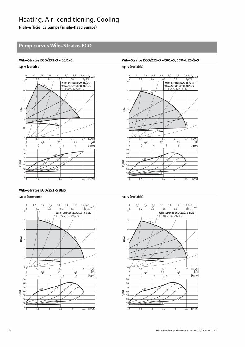
46 Subject to change without prior notice 09/2006 WILO AG
Heating, Air-conditioning, CoolingHigh-efficiency pumps (single-head pumps)
Pump curves Wilo-Stratos ECO
Wilo-Stratos ECO/251-3 - 30/1-3 Wilo-Stratos ECO/251-5 -/301-5, ECO-L 25/1-5
p-v (variable) p-v (variable)
Wilo-Stratos ECO/251-5 BMS
p-c (constant) p-v (variable)
Pump
Curves
max.
H [m
]
0
2
2,5
3
1
0,5
1,5
0 0,5
0 0,2 0,4 0,6
0 2 4 6 8
1 1,5 2 2,5
[m³/h]1,51 2,520 0,5
[m³/h][l/s]
[lgpm]
0
20
15
10
5
25
30
35
P 1 [W
]
Q
2 m 1,5 m
1 m
min.
p-v
max.
min.
2,5 m
Wilo-Stratos ECO 25/1-3Wilo-Stratos ECO 30/1-31 ~ 230 V - Rp 1/ Rp 1¼
[m/s]0 0,80,2 0,4
0,20 0,4 0,6 0,8 1,0 1,2 1,4
0,6 Rp 1¼
Rp 1
max.
H [m
]
0
4
5
6
2
1
3
[m/s]0 0,80,2 0,4
0,20 0,4 0,6 0,8 1,0 1,2 1,4
0,6
0 0,5
0 0,2 0,4 0,6
0 2 4 6 8
1 1,5 2 2,5
[m³/h]1,51 2,520 0,5
[m³/h][l/s]
[lgpm]
0
40
30
20
10
50
60
70
P 1 [W
]
Q
4 m 3 m
2 m
1 m
p-v
ma
x.
min.
min.
5 m
Wilo-Stratos ECO 25/1-5Wilo-Stratos ECO 30/1-51 ~ 230 V - Rp 1/ Rp 1¼
Rp 1¼
Rp 1
max.
H [m
]
0
4
5
6
2
1
3
[m/s]0 0,8 0,2 0,4
0,2 0 0,4 0,6 0,8 1,0 1,2 1,4
0,6
0 0,5
0 0,2 0,4 0,6
0 2 4 6 8
1 1,5 2 2,5
[m³/h]1,5 1 2,5 2 0 0,5
[m³/h][l/s]
[lgpm]
0
40
30
20
10
50
60
70
P 1[W
]
Q
4 m
3 m
2 m
1 m
p-c
max.
min.
min.
5 m
Rp 1¼
Rp 1
Wilo-Stratos ECO 25/1-5 BMS1 ~ 230 V - Rp 1/ Rp 1¼
max.
H [m
]
0
4
5
6
2
1
3
[m/s]0 0,8 0,2 0,4
0,2 0 0,4 0,6 0,8 1,0 1,2 1,4
0,6
0 0,5
0 0,2 0,4 0,6
0 2 4 6 8
1 1,5 2 2,5
[m³/h]1,5 1 2,5 2 0 0,5
[m³/h][l/s]
[lgpm]
0
40
30
20
10
50
60
70
P 1[W
]
Q
4 m
3 m
2 m
1 m
p-v
ma
x.
min.
min.
5 m
Rp 1¼
Rp 1
Wilo-Stratos ECO 25/1-5 BMS1 ~ 230 V - Rp 1/ Rp 1¼
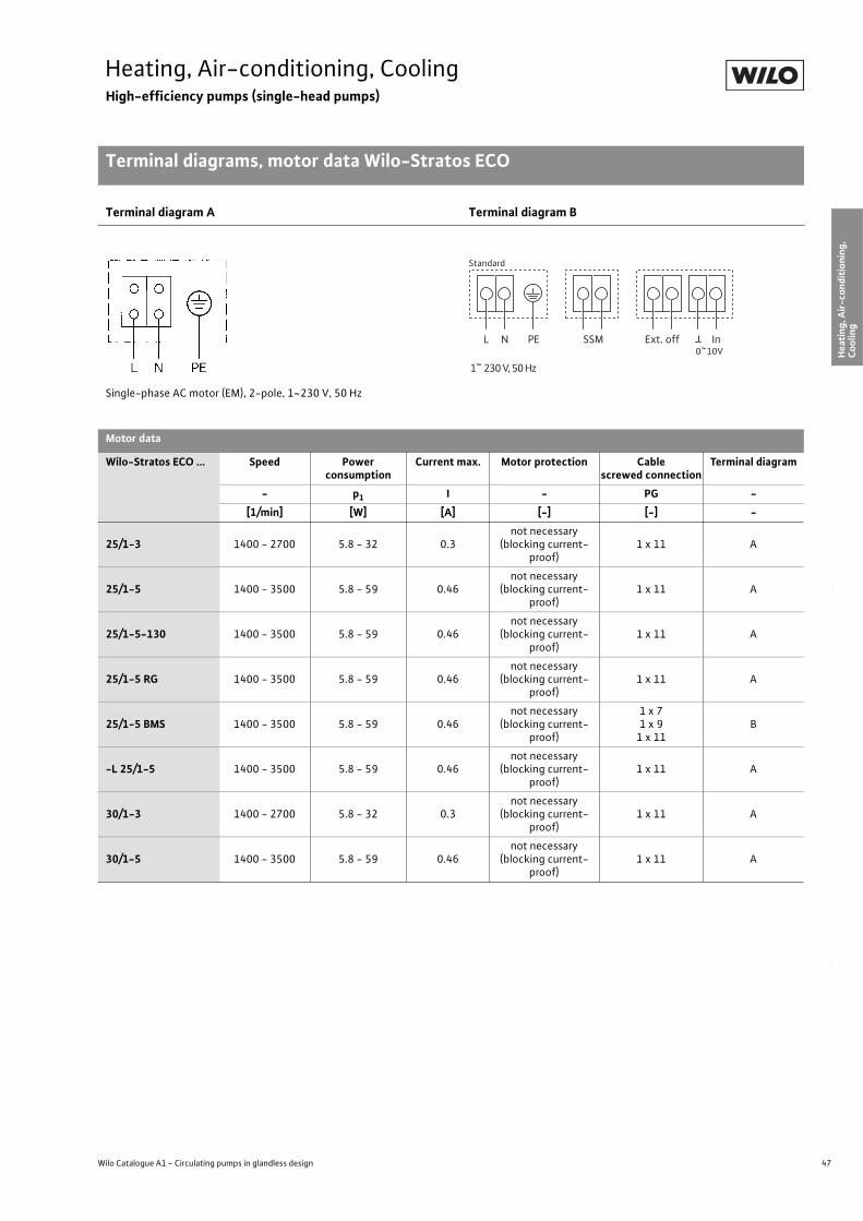
47
Heating, Air-conditioning, CoolingHigh-efficiency pumps (single-head pumps)
Terminal diagrams, motor data Wilo-Stratos ECO
Wilo Catalogue A1 - Circulating pumps in glandless design
Hea
tin
g, A
ir-c
on
dit
ion
ing
, C
oo
ling
Po
tab
le w
ater
cir
cula
tio
nSo
lar
ther
mal
Serv
ice/
Acc
esso
ries
, Sys
tem
sSw
itch
gea
rs a
nd
Co
ntr
ol
Dev
ices
P
um
p M
anag
emen
t S y
stem
s
Terminal diagram A Terminal diagram B
Single-phase AC motor (EM), 2-pole, 1~230 V, 50 Hz
Motor data
Wilo-Stratos ECO ... Speed Power consumption
Current max. Motor protection Cablescrewed connection
Terminal diagram
- p1 I - PG -
[1/min] [W] [A] [-] [-] -
25/1-3 1400 - 2700 5.8 - 32 0.3not necessary
(blocking current-proof)
1 x 11 A
25/1-5 1400 - 3500 5.8 - 59 0.46not necessary
(blocking current-proof)
1 x 11 A
25/1-5-130 1400 - 3500 5.8 - 59 0.46not necessary
(blocking current-proof)
1 x 11 A
25/1-5 RG 1400 - 3500 5.8 - 59 0.46not necessary
(blocking current-proof)
1 x 11 A
25/1-5 BMS 1400 - 3500 5.8 - 59 0.46not necessary
(blocking current-proof)
1 x 71 x 9
1 x 11B
-L 25/1-5 1400 - 3500 5.8 - 59 0.46not necessary
(blocking current-proof)
1 x 11 A
30/1-3 1400 - 2700 5.8 - 32 0.3not necessary
(blocking current-proof)
1 x 11 A
30/1-5 1400 - 3500 5.8 - 59 0.46not necessary
(blocking current-proof)
1 x 11 A
0~10V
Standard
L N PE SSM InExt. off
1~ 230 V, 50 Hz
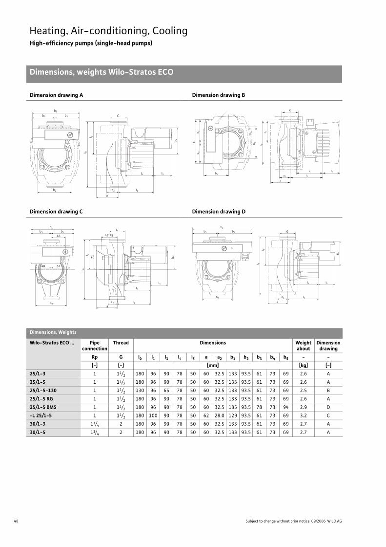
48 Subject to change without prior notice 09/2006 WILO AG
Heating, Air-conditioning, CoolingHigh-efficiency pumps (single-head pumps)
Dimensions, weights Wilo-Stratos ECO
Dimension drawing A Dimension drawing B
Dimension drawing C Dimension drawing D
Dimensions, Weights
Wilo-Stratos ECO ... Pipe connection
Thread Dimensions Weight about
Dimension drawing
Rp G l0 l1 l3 l4 l5 a a2 b1 b2 b3 b4 b5 - -
[-] [-] [mm] [kg] [-]
25/1-3 1 11/2 180 96 90 78 50 60 32.5 133 93.5 61 73 69 2.6 A
25/1-5 1 11/2 180 96 90 78 50 60 32.5 133 93.5 61 73 69 2.6 A
25/1-5-130 1 11/2 130 96 65 78 50 60 32.5 133 93.5 61 73 69 2.5 B
25/1-5 RG 1 11/2 180 96 90 78 50 60 32.5 133 93.5 61 73 69 2.6 A
25/1-5 BMS 1 11/2 180 96 90 78 50 60 32.5 185 93.5 78 73 94 2.9 D
-L 25/1-5 1 11/2 180 100 90 78 50 62 28.0 129 93.5 61 73 69 3.2 C
30/1-3 11/4 2 180 96 90 78 50 60 32.5 133 93.5 61 73 69 2.7 A
30/1-5 11/4 2 180 96 90 78 50 60 32.5 133 93.5 61 73 69 2.7 A
G
a
b1
b3
b2 a2
b5
I4 I5
I1
I 0
l 3
b4
b1
b3
b5
b2
b4
I4 I5
I1
I 0
l 3
a
a2
G
b1
b2
48 57
71
43 47,75
G
a2
a
b3 b5
I4
I5
I1
I 0
l 3
b4
b1
b3
b2
b5 G
a
a2
I4 I5
I1
I 0
l 3
b4

49
Heating, Air-conditioning, CoolingHigh-efficiency pumps (single-head pumps)
Wilo Catalogue A1 - Circulating pumps in glandless design
Hea
tin
g, A
ir-c
on
dit
ion
ing
, C
oo
ling
Po
tab
le w
ater
cir
cula
tio
nSo
lar
ther
mal
Serv
ice/
Acc
esso
ries
, Sys
tem
sSw
itch
gea
rs a
nd
Co
ntr
ol
Dev
ices
P
um
p M
anag
emen
t S y
stem
s
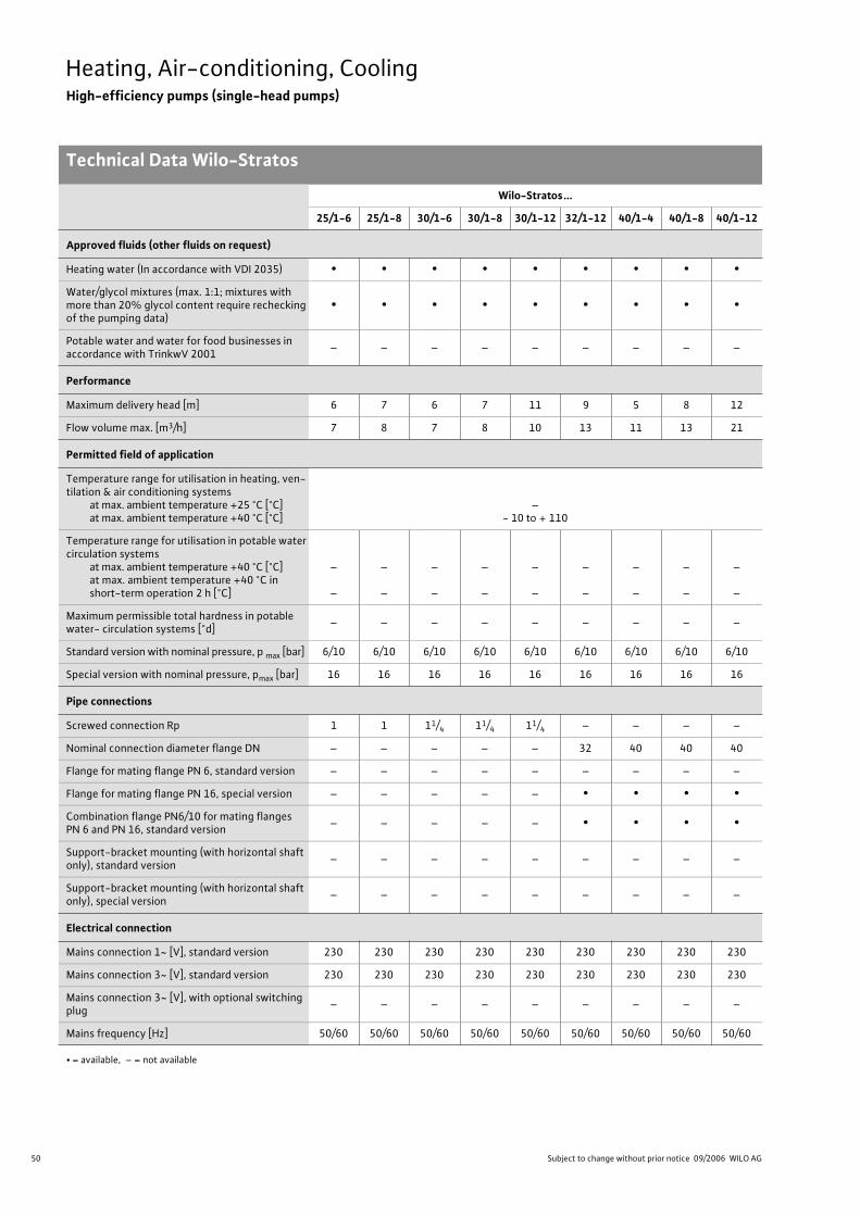
50 Subject to change without prior notice 09/2006 WILO AG
Heating, Air-conditioning, CoolingHigh-efficiency pumps (single-head pumps)
Technical Data Wilo-Stratos
Wilo-Stratos...
25/1-6 25/1-8 30/1-6 30/1-8 30/1-12 32/1-12 40/1-4 40/1-8 40/1-12
Approved fluids (other fluids on request)
Heating water (In accordance with VDI 2035) • • • • • • • • •
Water/glycol mixtures (max. 1:1; mixtures with more than 20% glycol content require rechecking of the pumping data)
• • • • • • • • •
Potable water and water for food businesses in accordance with TrinkwV 2001
– – – – – – – – –
Performance
Maximum delivery head [m] 6 7 6 7 11 9 5 8 12
Flow volume max. [m3/h] 7 8 7 8 10 13 11 13 21
Permitted field of application
Temperature range for utilisation in heating, ven-tilation & air conditioning systems
at max. ambient temperature +25 °C [°C]at max. ambient temperature +40 °C [°C]
–- 10 to + 110
Temperature range for utilisation in potable water circulation systems
at max. ambient temperature +40 °C [°C]at max. ambient temperature +40 °C in short-term operation 2 h [°C]
–
–
–
–
–
–
–
–
–
–
–
–
–
–
–
–
–
–
Maximum permissible total hardness in potable water- circulation systems [°d]
– – – – – – – – –
Standard version with nominal pressure, p max [bar] 6/10 6/10 6/10 6/10 6/10 6/10 6/10 6/10 6/10
Special version with nominal pressure, pmax [bar] 16 16 16 16 16 16 16 16 16
Pipe connections
Screwed connection Rp 1 1 11/4 11/4 11/4 – – – –
Nominal connection diameter flange DN – – – – – 32 40 40 40
Flange for mating flange PN 6, standard version – – – – – – – – –
Flange for mating flange PN 16, special version – – – – – • • • •
Combination flange PN6/10 for mating flanges PN 6 and PN 16, standard version
– – – – – • • • •
Support-bracket mounting (with horizontal shaft only), standard version
– – – – – – – – –
Support-bracket mounting (with horizontal shaft only), special version
– – – – – – – – –
Electrical connection
Mains connection 1~ [V], standard version 230 230 230 230 230 230 230 230 230
Mains connection 3~ [V], standard version 230 230 230 230 230 230 230 230 230
Mains connection 3~ [V], with optional switching plug
– – – – – – – – –
Mains frequency [Hz] 50/60 50/60 50/60 50/60 50/60 50/60 50/60 50/60 50/60
• = available, – = not available
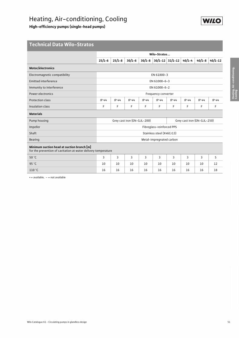
51
Heating, Air-conditioning, CoolingHigh-efficiency pumps (single-head pumps)
Technical Data Wilo-Stratos
Wilo Catalogue A1 - Circulating pumps in glandless design
Hea
tin
g, A
ir-c
on
dit
ion
ing
, C
oo
ling
Po
tab
le w
ater
cir
cula
tio
nSo
lar
ther
mal
Serv
ice/
Acc
esso
ries
, Sys
tem
sSw
itch
gea
rs a
nd
Co
ntr
ol
Dev
ices
P
um
p M
anag
emen
t S y
stem
s
Motor/electronics
Electromagnetic compatibility EN 61800-3
Emitted interference EN 61000-6-3
Immunity to interference EN 61000-6-2
Power electronics Frequency converter
Protection class IP 44 IP 44 IP 44 IP 44 IP 44 IP 44 IP 44 IP 44 IP 44
Insulation class F F F F F F F F F
Materials
Pump housing Grey cast iron (EN-GJL-200) Grey cast iron (EN-GJL-250)
Impeller Fibreglass-reinforced PPS
Shaft Stainless steel (X46Cr13)
Bearing Metal-impregnated carbon
Minimum suction head at suction branch [m] for the prevention of cavitation at water delivery temperature
50 °C 3 3 3 3 3 3 3 3 5
95 °C 10 10 10 10 10 10 10 10 12
110 °C 16 16 16 16 16 16 16 16 18
Wilo-Stratos...
25/1-6 25/1-8 30/1-6 30/1-8 30/1-12 32/1-12 40/1-4 40/1-8 40/1-12
• = available, – = not available
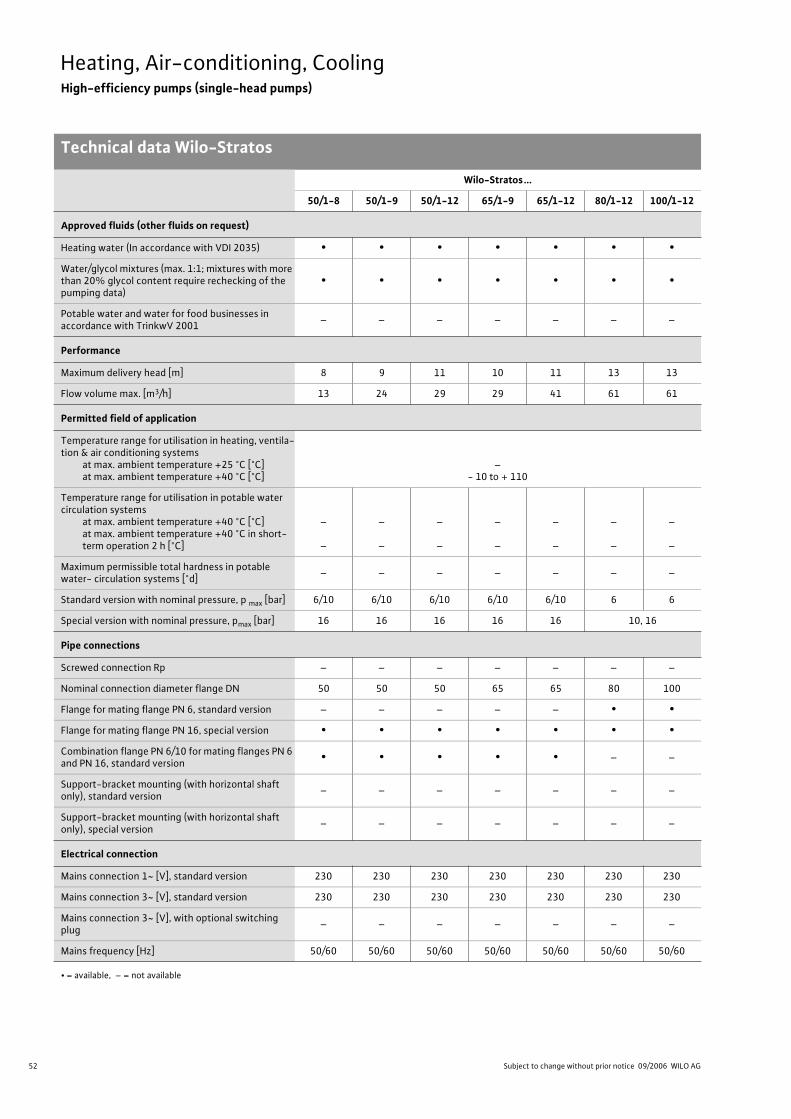
52 Subject to change without prior notice 09/2006 WILO AG
Heating, Air-conditioning, CoolingHigh-efficiency pumps (single-head pumps)
Technical data Wilo-Stratos
Wilo-Stratos...
50/1-8 50/1-9 50/1-12 65/1-9 65/1-12 80/1-12 100/1-12
Approved fluids (other fluids on request)
Heating water (In accordance with VDI 2035) • • • • • • •
Water/glycol mixtures (max. 1:1; mixtures with more than 20% glycol content require rechecking of the pumping data)
• • • • • • •
Potable water and water for food businesses in accordance with TrinkwV 2001
– – – – – – –
Performance
Maximum delivery head [m] 8 9 11 10 11 13 13
Flow volume max. [m3/h] 13 24 29 29 41 61 61
Permitted field of application
Temperature range for utilisation in heating, ventila-tion & air conditioning systems
at max. ambient temperature +25 °C [°C]at max. ambient temperature +40 °C [°C]
–- 10 to + 110
Temperature range for utilisation in potable water circulation systems
at max. ambient temperature +40 °C [°C]at max. ambient temperature +40 °C in short-term operation 2 h [°C]
–
–
–
–
–
–
–
–
–
–
–
–
–
–
Maximum permissible total hardness in potable water- circulation systems [°d]
– – – – – – –
Standard version with nominal pressure, p max [bar] 6/10 6/10 6/10 6/10 6/10 6 6
Special version with nominal pressure, pmax [bar] 16 16 16 16 16 10, 16
Pipe connections
Screwed connection Rp – – – – – – –
Nominal connection diameter flange DN 50 50 50 65 65 80 100
Flange for mating flange PN 6, standard version – – – – – • •
Flange for mating flange PN 16, special version • • • • • • •
Combination flange PN 6/10 for mating flanges PN 6 and PN 16, standard version
• • • • • – –
Support-bracket mounting (with horizontal shaft only), standard version
– – – – – – –
Support-bracket mounting (with horizontal shaft only), special version
– – – – – – –
Electrical connection
Mains connection 1~ [V], standard version 230 230 230 230 230 230 230
Mains connection 3~ [V], standard version 230 230 230 230 230 230 230
Mains connection 3~ [V], with optional switching plug
– – – – – – –
Mains frequency [Hz] 50/60 50/60 50/60 50/60 50/60 50/60 50/60
• = available, – = not available

53
Heating, Air-conditioning, CoolingHigh-efficiency pumps (single-head pumps)
Technical data Wilo-Stratos
Wilo Catalogue A1 - Circulating pumps in glandless design
Hea
tin
g, A
ir-c
on
dit
ion
ing
, C
oo
ling
Po
tab
le w
ater
cir
cula
tio
nSo
lar
ther
mal
Serv
ice/
Acc
esso
ries
, Sys
tem
sSw
itch
gea
rs a
nd
Co
ntr
ol
Dev
ices
P
um
p M
anag
emen
t S y
stem
s
Motor/electronics
Electromagnetic compatibility EN 61800-3
Emitted interference EN 61000-6-3
Immunity to interference EN 61000-6-2
Power electronics Frequency converter
Protection class IP 44 IP 44 IP 44 IP 44 IP 44 IP 44 IP 44
Insulation class F F F F F F F
Materials
Pump housing Grey cast iron (EN-GJL-250)
Impeller Fibreglass-reinforced PPS Fibreglass-reinforced PP
Shaft Stainless steel (X46Cr13)
Bearing Metal-impregnated carbon
Minimum suction head at suction branch [m] for the prevention of cavitation at water delivery temperature
50 °C 3 5 5 5 7 7 7
95 °C 10 12 12 12 15 15 15
110 °C 16 18 18 18 23 23 23
Wilo-Stratos...
50/1-8 50/1-9 50/1-12 65/1-9 65/1-12 80/1-12 100/1-12
• = available, – = not available
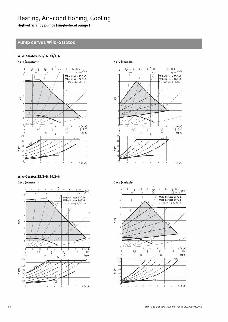
54 Subject to change without prior notice 09/2006 WILO AG
Heating, Air-conditioning, CoolingHigh-efficiency pumps (single-head pumps)
Pump curves Wilo-Stratos
Wilo-Stratos 251/-6, 30/1-6
p-c (constant) p-v (variable)
Wilo-Stratos 25/1-8, 30/1-8
p-c (constant) p-v (variable)
Q
min.
max.
H [m
]
0
4
5
7
6
2
1
3
Wilo-Stratos 25/1-6 Wilo-Stratos 30/1-6
1 ~ 230 V - Rp1 / Rp1¼
[m/s]
v210 2,5 31,5 3,50,5
0 0,5 1 21,5
[m³/h]640 2 5 731
[m³/h]640 2 5 731
[l/s]
[lgpm]
2
10 20
1,510,5
0
0
0
80
60
40
20
100
P 1 [W
]
1 m
2 m
3 m4 m5 m
6 mmax.
min.
max.
p-c
Rp 1¼
Rp 1
Q
min.
max.
H [m
]
0
4
5
7
6
2
1
3
Wilo-Stratos 25/1-6 Wilo-Stratos 30/1-6
1 ~ 230 V - Rp1 / Rp1¼
[m³/h]640 2 5 731
[m³/h]640 2 5 731
[l/s]
[lgpm]
2
10 20
1,510,5
0
0
0
80
60
40
20
100
P 1 [W
] 6 m 5 m 4 m
3 m
2 m
p-v
min.
max.
[m/s]
v210 2,5 31,5 3,50,5
0 0,5 1 21,5 Rp 1¼
Rp 1
0
4
5
7
6
8
2
1
3
H [m
]
Q
[m³/h][l/s]
[lgpm]
P 1 [W
]
0
80
60
40
20
100
120
140
Wilo-Stratos 25/1-8 Wilo-Stratos 30/1-8 1 ~ 230 V - Rp 1 / Rp 1 ¼
6 8 4 0 2 5 7 3 1
[m³/h]6 8 4 0 2 5 7 3 1
2
10 20
1,5 1 0,5
0
0
[m/s]2 1 0 2,5 1,5 0,5
v2 1 0 2,5 3 4 1,5 Rp 1
Rp 1 ¼
3,5 0,5
max.
max.
1 m 2 m
3 m 4 m
5 m
6 m
7 m
min.
p-c
max.
min.
0
4
5
7
6
8
2
1
3
H[m
]
Q
[l/s]
[lgpm]
P 1 [W
]
0
80
60
40
20
100
120
140
2
10 20
1,5 1 0,5
0
0
[m/s]2 1 0 2,5 1,5 0,5
v2 1 0 2,5 3 4 1,5 Rp 1
Rp 1 ¼
3,5 0,5
Wilo-Stratos 25/1-8 Wilo-Stratos 30/1-8 1 ~ 230 V - Rp 1 / Rp 1 ¼
[m³/h] 6 8 4 0 2 5 7 3 1
[m³/h]6 8 4 0 2 5 7 3 1
max.
min.
2 m 3 m 4 m
5 m 6 m
7 m
min.
max.
p-v
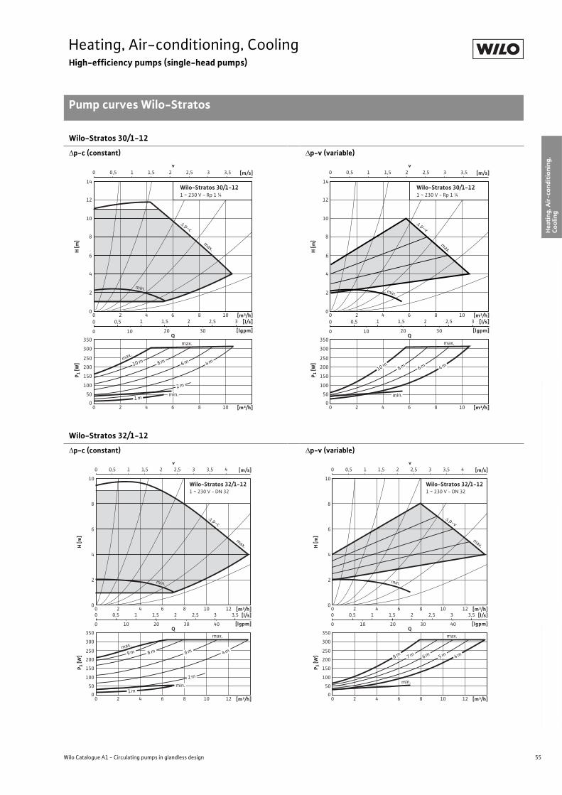
55
Heating, Air-conditioning, CoolingHigh-efficiency pumps (single-head pumps)
Pump curves Wilo-Stratos
Wilo Catalogue A1 - Circulating pumps in glandless design
Hea
tin
g, A
ir-c
on
dit
ion
ing
, C
oo
ling
Po
tab
le w
ater
cir
cula
tio
nSo
lar
ther
mal
Serv
ice/
Acc
esso
ries
, Sys
tem
sSw
itch
gea
rs a
nd
Co
ntr
ol
Dev
ices
P
um
p M
anag
emen
t S y
stem
s
Wilo-Stratos 30/1-12
p-c (constant) p-v (variable)
Wilo-Stratos 32/1-12
p-c (constant) p-v (variable)
v0 1 2 31,50,5 2,5 3,5 [m/s]
0
8
10
12
14
4
2
6
H [m
]
[m³/h][l/s]
[lgpm]
P 1 [W
]
0
250
200
100
150
50
300
350
Wilo-Stratos 30/1-121 ~ 230 V - Rp 1 ¼
80 4 1062
[m³/h]80 4 1062
1 1,5 2 32,5
10 20 30
0,5
0
0
Qmax.
max.
10 m 8 m 6 m 4 m
2 m
1 mmin.
min.
p-c
max.
v0 1 2 31,50,5 2,5 3,5 [m/s]
0
8
10
12
14
4
2
6
H [m
][m³/h]
[l/s]
[lgpm]
P 1 [W
]
0
250
200
100
150
50
300
350
Wilo-Stratos 30/1-121 ~ 230 V - Rp 1 ¼
80 4 1062
[m³/h]80 4 1062
1 1,5 2 32,5
10 20 30
0,5
0
0
Qmax.
10 m8 m 6 m 4 m
min.
min.
p-v
max.
v0 1 2 3 41,50,5 2,5 3,5 [m/s]
0
8
10
4
2
6
H [m
]
[m³/h][l/s]
[lgpm]
P 1 [W
]
0
250
200
100
150
50
300
350
Wilo-Stratos 32/1-121 ~ 230 V - DN 32
80 4 10 1262
[m³/h]80 4 10 1262
1 1,5 2 32,5 3,5
10 20 30 40
0,5
0
0
Qmax.
max.
8 m 6 m 4 m
2 m
9 m
1 mmin.
min.
p-c
max.
v0 1 2 3 41,50,5 2,5 3,5 [m/s]
0
8
10
4
2
6
H [m
]
[m³/h][l/s]
[lgpm]
P 1 [W
]
0
250
200
100
150
50
300
350
Wilo-Stratos 32/1-121 ~ 230 V - DN 32
80 4 10 1262
[m³/h]80 4 10 1262
1 1,5 2 32,5 3,5
10 20 30 40
0,5
0
0
Qmax.
min.
8 m 7 m 6 m 5 m 4 m
min.
p-v
max.
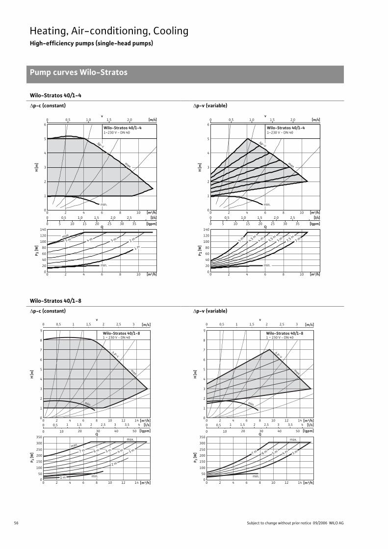
56 Subject to change without prior notice 09/2006 WILO AG
Heating, Air-conditioning, CoolingHigh-efficiency pumps (single-head pumps)
Pump curves Wilo-Stratos
Wilo-Stratos 40/1-4
p-c (constant) p-v (variable)
Wilo-Stratos 40/1-8
p-c (constant) p-v (variable)
0 0.5 1.0 1.5 2.0 [m/s]
0
1
2
3
4
5
6
0 2 4 6 8 10 [m³/h]
H [m
]
0 0.5 1.0 1.5 2.0 2.5 [l/s]
0 5 10 15 20 25 30 35 [Igpm]
0
20
40
60
80
100
120
140
0 2 4 6 8 10 [m³/h]
P 1 [W
]
v
Q
Wilo-Stratos 40/1-41~230 V - DN 40
max.
min.
min.
5 m 4 m 3 m 2 m
1 m
max.
∆p-c
0 0.5 1.0 1.5 2.0 [m/s]
0
1
2
3
4
5
6
0 2 4 6 8 10 [m³/h]
H [m
]
0 0.5 1.0 1.5 2.0 2.5 [l/s]
0 5 10 15 20 25 30 35 [Igpm]
0
20
40
60
80
100
120
140
0 2 4 6 8 10 [m³/h]
P 1 [W
]
v
Q
Wilo-Stratos 40/1-41~230 V - DN 40
max.
min.
min.
5 m 4.5 m
4 m 3 m 2 m3.5 m
2.5 m
∆p-v
0
8
9
4
2
6
7
3
1
5
H [m
]
[m³/h][l/s]
[lgpm]
Wilo-Stratos 40/1-81 ~ 230 V - DN 40
1280 4 10 1462
[m³/h]1280 4 10 1462
1,51 2,52 43,53
10 20 30 40 50
0,5
0
0
Q
P 1 [W
]
0
250
200
100
150
50
300
350
v0 1 2 31,50,5 2,5 [m/s]
max.
max.
7 m 6 m 5 m 4 m 3 m
2 m
1 m min.
p-c
min.
max.
0
8
9
4
2
6
7
3
1
5
H [m
]
[m³/h][l/s]
[lgpm]
Wilo-Stratos 40/1-81 ~ 230 V - DN 40
1280 4 10 1462
[m³/h]1280 4 10 1462
1,51 2,52 43,53
10 20 30 40 50
0,5
0
0
Q
P 1 [W
]
0
250
200
100
150
50
300
350
v0 1 2 31,50,5 2,5 [m/s]
min.
max.
7 m 6 m 5 m 4 m 3 m
min.
p-v
max.
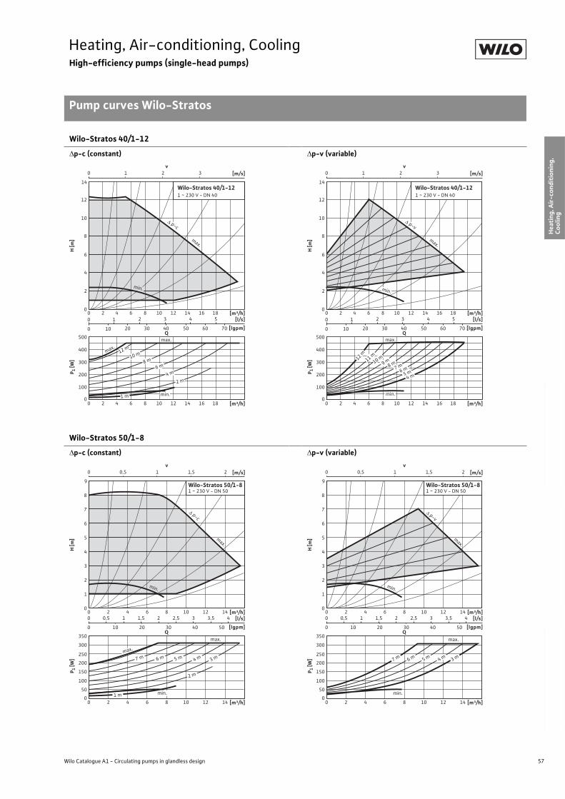
57
Heating, Air-conditioning, CoolingHigh-efficiency pumps (single-head pumps)
Pump curves Wilo-Stratos
Wilo Catalogue A1 - Circulating pumps in glandless design
Hea
tin
g, A
ir-c
on
dit
ion
ing
, C
oo
ling
Po
tab
le w
ater
cir
cula
tio
nSo
lar
ther
mal
Serv
ice/
Acc
esso
ries
, Sys
tem
sSw
itch
gea
rs a
nd
Co
ntr
ol
Dev
ices
P
um
p M
anag
emen
t S y
stem
s
Wilo-Stratos 40/1-12
p-c (constant) p-v (variable)
Wilo-Stratos 50/1-8
p-c (constant) p-v (variable)
v0 1 2 3 [m/s]
0
8
10
12
14
4
2
6
H [m
]
[m³/h][l/s]
[lgpm]
P 1 [W
]
0
300
200
100
400
500
Wilo-Stratos 40/1-121 ~ 230 V - DN 40
12 16 1880 4 10 1462
12 16 1880 4 10 1462 [m³/h]
2 3 4 5
10 20 30 40 50 60 70
1
0
0
Qmax.
8 m10 m
6 m
4 m
2 m
1 m
max.
min.
12 m
p-c
min.
max.
v0 1 2 3 [m/s]
0
8
10
12
14
4
2
6
H [m
]
[l/s]
[lgpm]
P 1 [W
]
0
300
200
100
400
500
Wilo-Stratos 40/1-121 ~ 230 V - DN 40
2 3 4 5
10 20 30 40 50 60 70
1
0
0
Q
[m³/h]12 16 1880 4 10 1462
12 16 1880 4 10 1462 [m³/h]
max.
9 m8 m10 m12 m
11 m
7 m6 m
5 m4 m
min.
p-v
max.
min.
v0 1 21,50,5 [m/s]
0
8
9
4
2
6
7
3
1
5
H [m
]
[m³/h][l/s]
[lgpm]
P 1 [W
]
0
250
200
100
150
50
300
350
Wilo-Stratos 50/1-81 ~ 230 V - DN 50
80 4 10 12 1462
[m³/h]80 4 10 12 1462
1 1,5 2 3 42,5 3,5
10 20 30 40 50
0,5
0
0
Q
min.
max.
7 m 6 m 5 m 4 m 3 m
2 m
1 m
max.
min.
p-c
max.
v0 1 21,50,5 [m/s]
0
8
9
4
2
6
7
3
1
5
H [m
]
[m³/h][l/s]
[lgpm]
P 1 [W
]
0
250
200
100
150
50
300
350
Wilo-Stratos 50/1-81 ~ 230 V - DN 50
80 4 10 12 1462
[m³/h]80 4 10 12 1462
1 1,5 2 3 42,5 3,5
10 20 30 40 50
0,5
0
0
Q
min.
7 m 6 m 5 m 4 m 3 m
max.
min.
p-v
max.
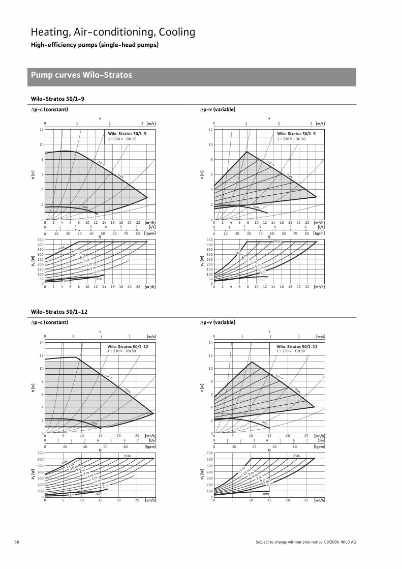
58 Subject to change without prior notice 09/2006 WILO AG
Heating, Air-conditioning, CoolingHigh-efficiency pumps (single-head pumps)
Pump curves Wilo-Stratos
Wilo-Stratos 50/1-9
p-c (constant) p-v (variable)
Wilo-Stratos 50/1-12
p-c (constant) p-v (variable)
v0 1 2 3 [m/s]
0
8
10
12
4
2
6
H [m
]
[m³/h][l/s]
[lgpm]
P 1 [W
]
0
350
100
50
400
450
200
150
250
300
12 16 18 20 2280 4 10 1462
12 16 18 20 2280 4 10 1462
2 3 4 5 6
10 20 30 40 50 60 70 80
1
0
0
Q
[m³/h]
Wilo-Stratos 50/1-91 ~ 230 V - DN 50
max.
8 m
7 m
min.
6 m
5 m
4 m
3 m2 m
1m
min.
p-c
max.
v0 1 2 3 [m/s]
0
8
10
12
4
2
6
H [m
]
[l/s]
[lgpm]
P 1 [W
]
0
350
100
50
400
450
200
150
250
300
2 3 4 5 6
10 20 30 40 50 60 70 80
1
0
0
Q
Wilo-Stratos 50/1-91 ~ 230 V - DN 50
[m³/h]12 16 18 20 2280 4 10 1462
12 16 18 20 2280 4 10 1462 [m³/h]
min.
max.
9 m
8 m
7 m6 m
5 m4 m
3 m
min.
p-v
max.
v0 1 32 [m/s]
0
12
14
4
2
8
10
6
H [m
]
[m³/h][l/s]
[lgpm]
P 1 [W
]
0
500
400
200
300
100
600
700
100 15 20 255
[m³/h]100 15 20 255
2 3 4 65 7
20 40 60 80
1
0
0
Q
Wilo-Stratos 50/1-121 ~ 230 V - DN 50
9 m
7 m
max.
min.
6 m5 m
4 m3 m
2 m
1m
max.
11 m
10 m
8 m
min.
p-c
max.
v0 1 32 [m/s]
0
12
14
4
2
8
10
6
H [m
]
[m³/h][l/s]
[lgpm]
P 1 [W
]
0
500
400
200
300
100
600
700
100 15 20 255
[m³/h]100 15 20 255
2 3 4 65 7
20 40 60 80
1
0
0
Q
Wilo-Stratos 50/1-121 ~ 230 V - DN 50
min.
max.
11 m
10 m9 m
8 m7 m
6 m5 m
4 m
min.
p-v
max.
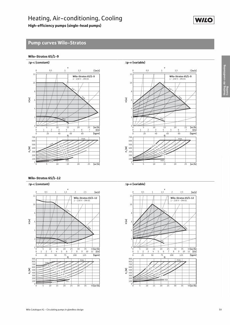
59
Heating, Air-conditioning, CoolingHigh-efficiency pumps (single-head pumps)
Pump curves Wilo-Stratos
Wilo Catalogue A1 - Circulating pumps in glandless design
Hea
tin
g, A
ir-c
on
dit
ion
ing
, C
oo
ling
Po
tab
le w
ater
cir
cula
tio
nSo
lar
ther
mal
Serv
ice/
Acc
esso
ries
, Sys
tem
sSw
itch
gea
rs a
nd
Co
ntr
ol
Dev
ices
P
um
p M
anag
emen
t S y
stem
s
Wilo-Stratos 65/1-9
p-c (constant) p-v (variable)
Wilo-Stratos 65/1-12
p-c (constant) p-v (variable)
v0 10,5 1,5 2 [m/s]
0
12
4
2
8
10
6
H [m
]
[m³/h][l/s]
[lgpm]
P 1 [W
]
0
500
400
200
300
100
600
700
100 15 20 255
[m³/h]100 15 20 255
2 3 4 65 7
20 40 60 80
1
0
0
Q
Wilo-Stratos 65/1-91 ~ 230 V - DN 65
8 m9 m
7 m
max.
min.
6 m
5 m4 m3 m2 m
1 m
max.
min.
p-c
max.
v0 10,5 1,5 2 [m/s]
0
12
4
2
8
10
6
H [m
][m³/h]
[l/s]
[lgpm]
P 1 [W
]
0
500
400
200
300
100
600
700
100 15 20 255
[m³/h]100 15 20 255
2 3 4 65 7
20 40 60 80
1
0
0
Q
Wilo-Stratos 65/1-91 ~ 230 V - DN 65
9 m10 m
8 m
min.
7 m
5 m4 m
max.
6 m
min.
p-v
max.
v0 10,5 1,5 2,52 [m/s]
0
12
4
2
8
10
6
H [m
]
[m³/h][l/s]
[lgpm]
P 1 [W
]
0
500
400
200
300
100
600
900
700
800
100 15 20 25 30 35 405
[m³/h]100 15 20 25 30 35 405
2 3 4 65 7 8 109 11
25 50 75 100 125
1
0
0
Q
Wilo-Stratos 65/1-121 ~ 230 V - DN 65
max.
max.
2 m
1 m
3 m4 m
5 m6 m
7 m8 m
min.
9 m10 m
min.
p-c
max.
v0 10,5 1,5 2,52 [m/s]
0
12
4
2
8
10
6
H [m
]
[m³/h][l/s]
[lgpm]
P 1 [W
]
0
500
400
200
300
100
600
900
700
800
100 15 20 25 30 35 405
[m³/h]100 15 20 25 30 35 405
2 3 4 65 7 8 109 11
25 50 75 100 125
1
0
0
Q
Wilo-Stratos 65/1-121 ~ 230 V - DN 65
min.
max.
4 m5 m6 m
7 m8 m
9 m10 m
min.
p-v
max.
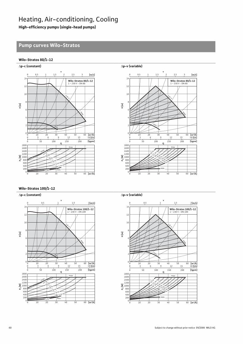
60 Subject to change without prior notice 09/2006 WILO AG
Heating, Air-conditioning, CoolingHigh-efficiency pumps (single-head pumps)
Pump curves Wilo-Stratos
Wilo-Stratos 80/1-12
p-c (constant) p-v (variable)
Wilo-Stratos 100/1-12
p-c (constant) p-v (variable)
v0 1 1,50,5 32 2,5 [m/s]
0
12
14
4
2
8
10
6
H [m
]
[m³/h][l/s]
[lgpm]
P 1 [W
]
0
1400
1200
800
1000
600
400
200
1600
1800
200 30 40 50 6010
[m³/h]200 30 40 50 6010
3 6 9 1512 18
50 100 150 2000
0
Q
Wilo-Stratos 80/1-121 ~ 230 V - DN 80
max.
max.
1 m min.
2 m4 m
6 m8 m
10 m12 m
min.
p-c
max.
v0 1 1,50,5 32 2,5 [m/s]
0
12
14
4
2
8
10
6
H [m
]
[m³/h][l/s]
[lgpm]
P 1 [W
]
0
1400
1200
800
1000
600
400
200
1600
1800
200 30 40 50 6010
[m³/h]200 30 40 50 6010
3 6 9 1512 18
50 100 150 2000
0
Q
Wilo-Stratos 80/1-121 ~ 230 V - DN 80
min.
4 m6 m7 m8 m9 m10 m11 m12 m
5 m
max.
min.
p-v
max.
v0 1 1,50,5 2[m/s]
0
12
14
4
2
8
10
6
H [m
]
[m³/h][l/s]
[lgpm]
P 1 [W
]
0
1400
1200
800
1000
600
400
200
1600
1800
200 30 40 50 6010
[m³/h]200 30 40 50 6010
3 6 9 1512 18
50 100 150 2000
0
Q
Wilo-Stratos 100/1-121 ~ 230 V - DN 100
max.
max.
1 m min.
2 m4 m
6 m8 m
10 m12 m
min.
p-c
max.
0
12
14
4
2
8
10
6
H [m
]
[m³/h][l/s]
[lgpm]
P 1 [W
]
0
1400
1200
800
1000
600
400
200
1600
1800
200 30 40 50 6010
[m³/h]200 30 40 50 6010
3 6 9 1512 18
50 100 150 2000
0
Q
Wilo-Stratos 100/1-121 ~ 230 V - DN 100
min.
4 m6 m7 m8 m9 m10 m11 m12 m
5 m
max.
min.
p-v
max.
v0 1 1,50,5 2[m/s]
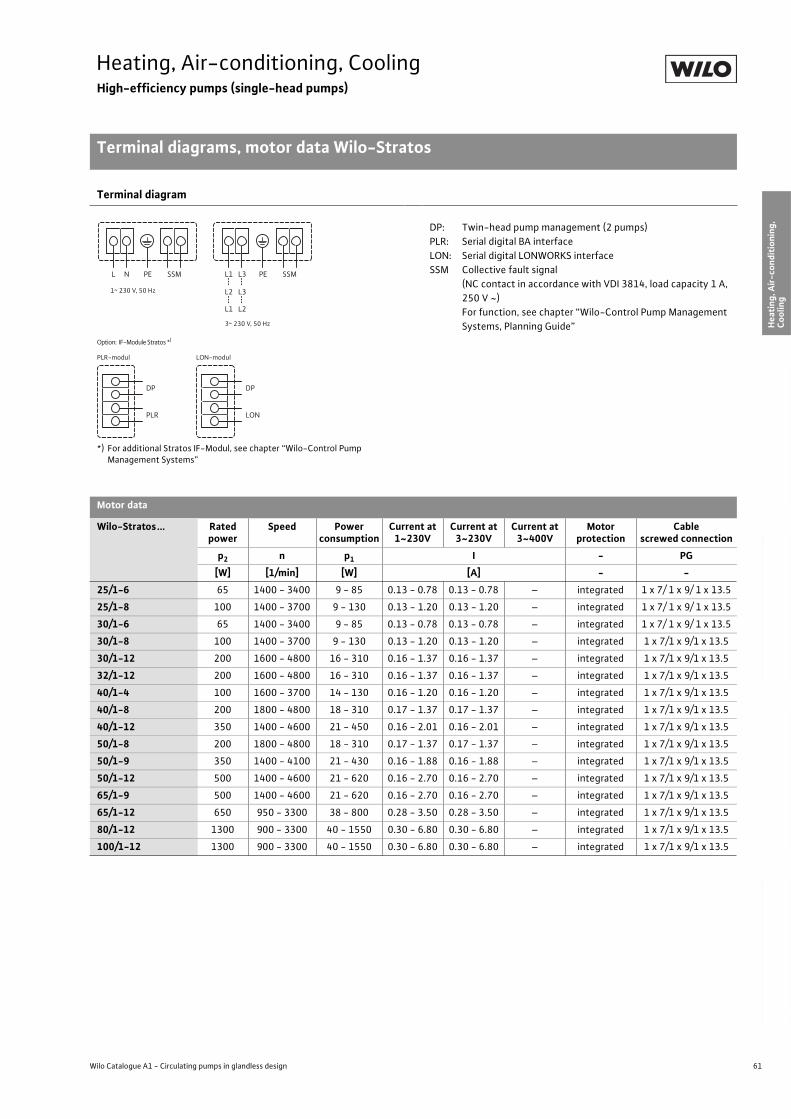
61
Heating, Air-conditioning, CoolingHigh-efficiency pumps (single-head pumps)
Terminal diagrams, motor data Wilo-Stratos
Wilo Catalogue A1 - Circulating pumps in glandless design
Hea
tin
g, A
ir-c
on
dit
ion
ing
, C
oo
ling
Po
tab
le w
ater
cir
cula
tio
nSo
lar
ther
mal
Serv
ice/
Acc
esso
ries
, Sys
tem
sSw
itch
gea
rs a
nd
Co
ntr
ol
Dev
ices
P
um
p M
anag
emen
t S y
stem
s
Terminal diagram
*) For additional Stratos IF-Modul, see chapter “Wilo-Control Pump Management Systems”
DP: Twin-head pump management (2 pumps)
PLR: Serial digital BA interface
LON: Serial digital LONWORKS interface
SSM Collective fault signal
(NC contact in accordance with VDI 3814, load capacity 1 A,
250 V ~)
For function, see chapter “Wilo-Control Pump Management
Systems, Planning Guide”
Motor data
Wilo-Stratos... Rated power
Speed Power consumption
Current at1~230V
Current at3~230V
Current at3~400V
Motor protection
Cablescrewed connection
p2 n p1 I - PG
[W] [1/min] [W] [A] - -
25/1-6 65 1400 - 3400 9 - 85 0.13 - 0.78 0.13 - 0.78 – integrated 1 x 7/ 1 x 9/ 1 x 13.5
25/1-8 100 1400 - 3700 9 - 130 0.13 - 1.20 0.13 - 1.20 – integrated 1 x 7/ 1 x 9/ 1 x 13.5
30/1-6 65 1400 - 3400 9 - 85 0.13 - 0.78 0.13 - 0.78 – integrated 1 x 7/ 1 x 9/ 1 x 13.5
30/1-8 100 1400 - 3700 9 - 130 0.13 - 1.20 0.13 - 1.20 – integrated 1 x 7/1 x 9/1 x 13.5
30/1-12 200 1600 - 4800 16 - 310 0.16 - 1.37 0.16 - 1.37 – integrated 1 x 7/1 x 9/1 x 13.5
32/1-12 200 1600 - 4800 16 - 310 0.16 - 1.37 0.16 - 1.37 – integrated 1 x 7/1 x 9/1 x 13.5
40/1-4 100 1600 - 3700 14 - 130 0.16 - 1.20 0.16 - 1.20 – integrated 1 x 7/1 x 9/1 x 13.5
40/1-8 200 1800 - 4800 18 - 310 0.17 - 1.37 0.17 - 1.37 – integrated 1 x 7/1 x 9/1 x 13.5
40/1-12 350 1400 - 4600 21 - 450 0.16 - 2.01 0.16 - 2.01 – integrated 1 x 7/1 x 9/1 x 13.5
50/1-8 200 1800 - 4800 18 - 310 0.17 - 1.37 0.17 - 1.37 – integrated 1 x 7/1 x 9/1 x 13.5
50/1-9 350 1400 - 4100 21 - 430 0.16 - 1.88 0.16 - 1.88 – integrated 1 x 7/1 x 9/1 x 13.5
50/1-12 500 1400 - 4600 21 - 620 0.16 - 2.70 0.16 - 2.70 – integrated 1 x 7/1 x 9/1 x 13.5
65/1-9 500 1400 - 4600 21 - 620 0.16 - 2.70 0.16 - 2.70 – integrated 1 x 7/1 x 9/1 x 13.5
65/1-12 650 950 - 3300 38 - 800 0.28 - 3.50 0.28 - 3.50 – integrated 1 x 7/1 x 9/1 x 13.5
80/1-12 1300 900 - 3300 40 - 1550 0.30 - 6.80 0.30 - 6.80 – integrated 1 x 7/1 x 9/1 x 13.5
100/1-12 1300 900 - 3300 40 - 1550 0.30 - 6.80 0.30 - 6.80 – integrated 1 x 7/1 x 9/1 x 13.5
L N PE SSM L1 L3
L2 L3
L1 L2
PE SSM
DP
PLR
DP
LON
Option: IF-Module Stratos *)
PLR-modul LON-modul
1~ 230 V, 50 Hz
3~ 230 V, 50 Hz
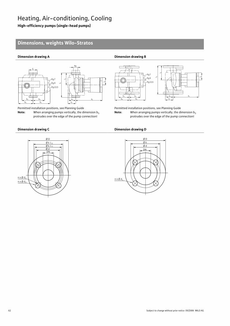
62 Subject to change without prior notice 09/2006 WILO AG
Heating, Air-conditioning, CoolingHigh-efficiency pumps (single-head pumps)
Dimensions, weights Wilo-Stratos
Dimension drawing A
Permitted installation positions, see Planning Guide
Note: When arranging pumps vertically, the dimension b5
protrudes over the edge of the pump connection!
Dimension drawing B
Permitted installation positions, see Planning Guide
Note: When arranging pumps vertically, the dimension b5
protrudes over the edge of the pump connection!
Dimension drawing C Dimension drawing D
l 0
l 2
a2 a1
Pg 7
b3b3
G
b5b4
Pg 9
Pg 13,5
a3
Rpl 1
l 0 l 2
a2 a1
Pg 7
b3b3
b5b4
Pg 9
Pg 13,5
a3
l 1
Ø D
n x Ø d
Ø k
DN
L2
Ø k Ø d
L 1
1
n x Ø d 2
n x Ø d
Ø D Ø k
DN
Ø d
L
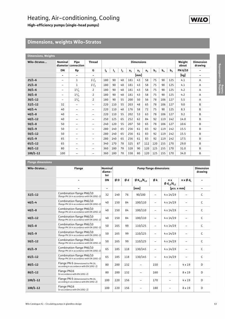
63
Heating, Air-conditioning, CoolingHigh-efficiency pumps (single-head pumps)
Dimensions, weights Wilo-Stratos
Wilo Catalogue A1 - Circulating pumps in glandless design
Hea
tin
g, A
ir-c
on
dit
ion
ing
, C
oo
ling
Po
tab
le w
ater
cir
cula
tio
nSo
lar
ther
mal
Serv
ice/
Acc
esso
ries
, Sys
tem
sSw
itch
gea
rs a
nd
Co
ntr
ol
Dev
ices
P
um
p M
anag
emen
t S y
stem
s
Dimensions, Weights
Wilo-Stratos... Nominal diameter
Pipe connection
Thread Dimensions Weight about
Dimensiondrawing
DN Rp G l0 l1 l2 a1 a2 a3 b3 b4 b5 PN 6/10 -
- - - [mm] [kg] -
25/1-6 – 1 11/2 180 90 48 181 43 58 75 90 125 4.1 A
25/1-8 – 1 11/2 180 90 48 181 43 58 75 90 125 4.1 A
30/1-6 – 11/4 2 180 90 48 181 43 58 75 90 125 4.2 A
30/1-8 – 11/4 2 180 90 48 181 43 58 75 90 125 4.2 A
30/1-12 – 11/4 2 180 90 55 200 50 56 78 106 127 5.5 A
32/1-12 32 – – 220 110 55 203 48 65 78 106 127 9.0 B
40/1-4 40 – – 220 110 48 176 58 72 75 90 125 8.3 B
40/1-8 40 – – 220 110 55 202 53 63 78 106 127 9.2 B
40/1-12 40 – – 250 125 65 252 62 84 92 119 142 14.0 B
50/1-8 50 – – 240 120 55 207 50 65 78 106 127 10.6 B
50/1-9 50 – – 280 140 65 256 61 83 92 119 142 15.5 B
50/1-12 50 – – 280 140 65 256 61 83 92 119 142 15.5 B
65/1-9 65 – – 280 140 65 256 61 83 92 119 142 17.5 B
65/1-12 65 – – 340 170 78 325 87 112 120 155 170 29.0 B
80/1-12 80 – – 360 180 78 328 90 120 125 155 170 31.0 B
100/1-12 100 – – 360 180 78 338 80 120 125 155 170 34.0 B
Flange dimensions
Wilo-Stratos... Flange Nominal diame-
ter
Pump flange dimensions Dimension drawing
- DN Ø D Ø d Ø KL1/KL2 Ø k n xØ dL1/dL2
n x Ø dL -
- - [mm] [pcs. x mm] -
32/1-12 Combination flange PN6/10(flange PN 16 in accordance with EN 1092-2)
32 140 76 90/100 – 4 x 14/19 – C
40/1-4 Combination flange PN6/10(flange PN 16 in accordance with EN 1092-2)
40 150 84 100/110 – 4 x 14/19 – C
40/1-8 Combination flange PN6/10(flange PN 16 in accordance with EN 1092-2)
40 150 84 100/110 – 4 x 14/19 – C
40/1-12 Combination flange PN6/10(flange PN 16 in accordance with EN 1092-2)
40 150 84 100/110 – 4 x 14/19 – C
50/1-8 Combination flange PN6/10(flange PN 16 in accordance with EN 1092-2)
50 165 99 110/125 – 4 x 14/19 – C
50/1-9 Combination flange PN6/10(flange PN 16 in accordance with EN 1092-2)
50 165 99 110/125 – 4 x 14/19 – C
50/1-12 Combination flange PN6/10(flange PN 16 in accordance with EN 1092-2)
50 165 99 110/125 – 4 x 14/19 – C
65/1-9 Combination flange PN6/10(flange PN 16 in accordance with EN 1092-2)
65 185 118 130/145 – 4 x 14/19 – C
65/1-12 Combination flange PN6/10(flange PN 16 in accordance with EN 1092-2)
65 185 118 130/145 – 4 x 14/19 – C
80/1-12 Flange PN 6 (dimensioned to PN 16, according in accordance with EN 1092-2)
80 200 132 – 150 – 4 x 19 D
80/1-12 Flange PN16 (in accordance with EN 1092-2)
80 200 132 – 160 – 8 x 19 D
100/1-12 Flange PN 6 (dimensioned to PN 16, according in accordance with EN 1092-2)
100 220 156 – 170 – 4 x 19 D
100/1-12 Flange PN16 (in accordance with EN 1092-2)
100 220 156 – 180 – 8 x 19 D
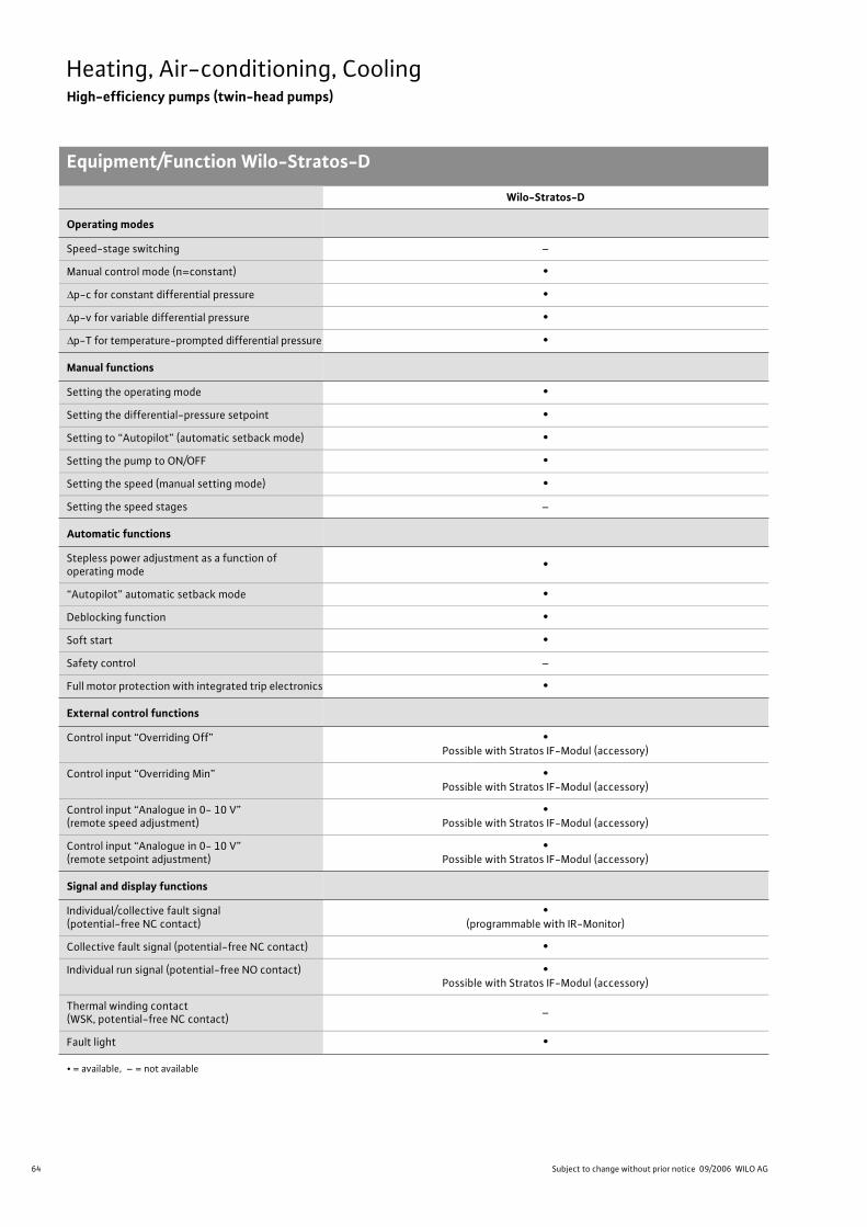
64 Subject to change without prior notice 09/2006 WILO AG
Heating, Air-conditioning, CoolingHigh-efficiency pumps (twin-head pumps)
Equipment/Function Wilo-Stratos-D
Wilo-Stratos-D
Operating modes
Speed-stage switching –
Manual control mode (n=constant) •
p-c for constant differential pressure •
p-v for variable differential pressure •
p-T for temperature-prompted differential pressure •
Manual functions
Setting the operating mode •
Setting the differential-pressure setpoint •
Setting to “Autopilot” (automatic setback mode) •
Setting the pump to ON/OFF •
Setting the speed (manual setting mode) •
Setting the speed stages –
Automatic functions
Stepless power adjustment as a function of operating mode
•
“Autopilot” automatic setback mode •
Deblocking function •
Soft start •
Safety control –
Full motor protection with integrated trip electronics •
External control functions
Control input “Overriding Off” •Possible with Stratos IF-Modul (accessory)
Control input “Overriding Min” •Possible with Stratos IF-Modul (accessory)
Control input “Analogue in 0- 10 V” (remote speed adjustment)
•Possible with Stratos IF-Modul (accessory)
Control input “Analogue in 0- 10 V” (remote setpoint adjustment)
•Possible with Stratos IF-Modul (accessory)
Signal and display functions
Individual/collective fault signal (potential-free NC contact)
•(programmable with IR-Monitor)
Collective fault signal (potential-free NC contact) •
Individual run signal (potential-free NO contact) •Possible with Stratos IF-Modul (accessory)
Thermal winding contact (WSK, potential-free NC contact)
–
Fault light •
• = available, – = not available
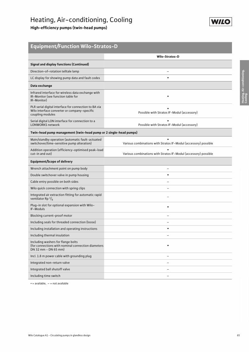
65
Heating, Air-conditioning, CoolingHigh-efficiency pumps (twin-head pumps)
Equipment/Function Wilo-Stratos-D
Wilo Catalogue A1 - Circulating pumps in glandless design
Hea
tin
g, A
ir-c
on
dit
ion
ing
, C
oo
ling
Po
tab
le w
ater
cir
cula
tio
nSo
lar
ther
mal
Serv
ice/
Acc
esso
ries
, Sys
tem
sSw
itch
gea
rs a
nd
Co
ntr
ol
Dev
ices
P
um
p M
anag
emen
t S y
stem
s
Signal and display functions (Continued)
Direction-of-rotation telltale lamp –
LC display for showing pump data and fault codes •
Data exchange
Infrared interface for wireless data exchange with IR-Monitor (see function table for IR-Monitor)
•
PLR serial digital interface for connection to BA via Wilo interface converter or company-specific coupling modules
•Possible with Stratos IF-Modul (accessory)
Serial digital LON interface for connection to a LONWORKS network
•Possible with Stratos IF-Modul (accessory)
Twin-head pump management (twin-head pump or 2 single-head pumps)
Main/standby operation (automatic fault-actuated switchover/time-sensitive pump alteration)
•Various combinations with Stratos IF-Modul (accessory) possible
Addition operation (efficiency-optimised peak-load cut-in and out)
•Various combinations with Stratos IF-Modul (accessory) possible
Equipment/Scope of delivery
Wrench attachment point on pump body –
Double switchover valve in pump housing •
Cable entry possible on both sides –
Wilo quick connection with spring clips –
Integrated air extraction fitting for automatic rapid ventilator Rp 3/8
–
Plug-in slot for optional expansion with Wilo-IF-Moduls
•
Blocking current-proof motor –
Including seals for threaded connection (loose) –
Including installation and operating instructions •
Including thermal insulation –
Including washers for flange bolts (for connections with nominal connection diameters DN 32 mm - DN 65 mm)
•
Incl. 1.8 m power cable with grounding plug –
Integrated non-return valve –
Integrated ball shutoff valve –
Including time switch –
Wilo-Stratos-D
• = available, – = not available
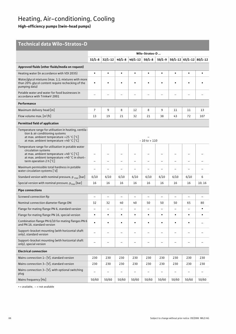
66 Subject to change without prior notice 09/2006 WILO AG
Heating, Air-conditioning, CoolingHigh-efficiency pumps (twin-head pumps)
Technical data Wilo-Stratos-Ds
Wilo-Stratos-D ...
32/1-8 32/1-12 40/1-8 40/1-12 50/1-8 50/1-9 50/1-12 65/1-12 80/1-12
Approved fluids (other fluids/media on request)
Heating water (In accordance with VDI 2035) • • • • • • • • •
Water/glycol mixtures (max. 1:1; mixtures with more than 20% glycol content require rechecking of the pumping data)
• • • • • • • • •
Potable water and water for food businesses in accordance with TrinkwV 2001
– – – – – – – – –
Performance
Maximum delivery head [m] 7 9 8 12 8 9 11 11 13
Flow volume max. [m3/h] 13 19 21 32 21 38 43 72 107
Permitted field of application
Temperature range for utilisation in heating, ventila-tion & air conditioning systemsat max. ambient temperature +25 °C [°C]at max. ambient temperature +40 °C [°C]
–- 10 to + 110
Temperature range for utilisation in potable water circulation systemsat max. ambient temperature +40 °C [°C]at max. ambient temperature +40 °C in short-term operation 2 h [°C]
–
–
–
–
–
–
–
–
–
–
–
–
–
–
–
–
–
–
Maximum permissible total hardness in potable water circulation systems [°d]
– – – – – – – – –
Standard version with nominal pressure, p max [bar] 6/10 6/10 6/10 6/10 6/10 6/10 6/10 6/10 6
Special version with nominal pressure, pmax [bar] 16 16 16 16 16 16 16 16 10, 16
Pipe connections
Screwed connection Rp – – – – – – – – –
Nominal connection diameter flange DN 32 32 40 40 50 50 50 65 80
Flange for mating flange PN 6, standard version – – – – – – – – •
Flange for mating flange PN 16, special version • • • • • • • • •
Combination flange PN 6/10 for mating flanges PN 6 and PN 16, standard version
• • • • • • • • –
Support-bracket mounting (with horizontal shaft only), standard version
– – – – – – – – –
Support-bracket mounting (with horizontal shaft only), special version
– – – – – – – – –
Electrical connection
Mains connection 1~ [V], standard version 230 230 230 230 230 230 230 230 230
Mains connection 3~ [V], standard version 230 230 230 230 230 230 230 230 230
Mains connection 3~ [V], with optional switching plug
– – – – – – – – –
Mains frequency [Hz] 50/60 50/60 50/60 50/60 50/60 50/60 50/60 50/60 50/60
• = available, – = not available

67
Heating, Air-conditioning, CoolingHigh-efficiency pumps (twin-head pumps)
Technical data Wilo-Stratos-D
Wilo Catalogue A1 - Circulating pumps in glandless design
Hea
tin
g, A
ir-c
on
dit
ion
ing
, C
oo
ling
Po
tab
le w
ater
cir
cula
tio
nSo
lar
ther
mal
Serv
ice/
Acc
esso
ries
, Sys
tem
sSw
itch
gea
rs a
nd
Co
ntr
ol
Dev
ices
P
um
p M
anag
emen
t S y
stem
s
Motor/electronics
Electromagnetic compatibility EN 61800-3
Emitted interference EN 61000-6-3
Immunity to interference EN 61000-6-2
Power electronics Frequency converter
Protection class IP 44 IP 44 IP 44 IP 44 IP 44 IP 44 IP 44 IP 44 IP 44
Insulation class F F F F F F F F F
Materials
Pump housing Grey cast iron (EN-GJL-250)
ImpellerFibreglass-reinforced PPS
Fibreglass-reinforced PP
Shaft Stainless steel (X46Cr13)
Bearing Metal-impregnated carbon
Minimum suction head at suction branch [m] for the prevention of cavitation at water delivery temperature
50 °C 3 3 3 5 3 5 5 7 7
95 °C 10 10 10 12 10 12 12 15 15
110 °C 16 16 16 18 16 18 18 23 23
Wilo-Stratos-D ...
32/1-8 32/1-12 40/1-8 40/1-12 50/1-8 50/1-9 50/1-12 65/1-12 80/1-12
• = available, – = not available
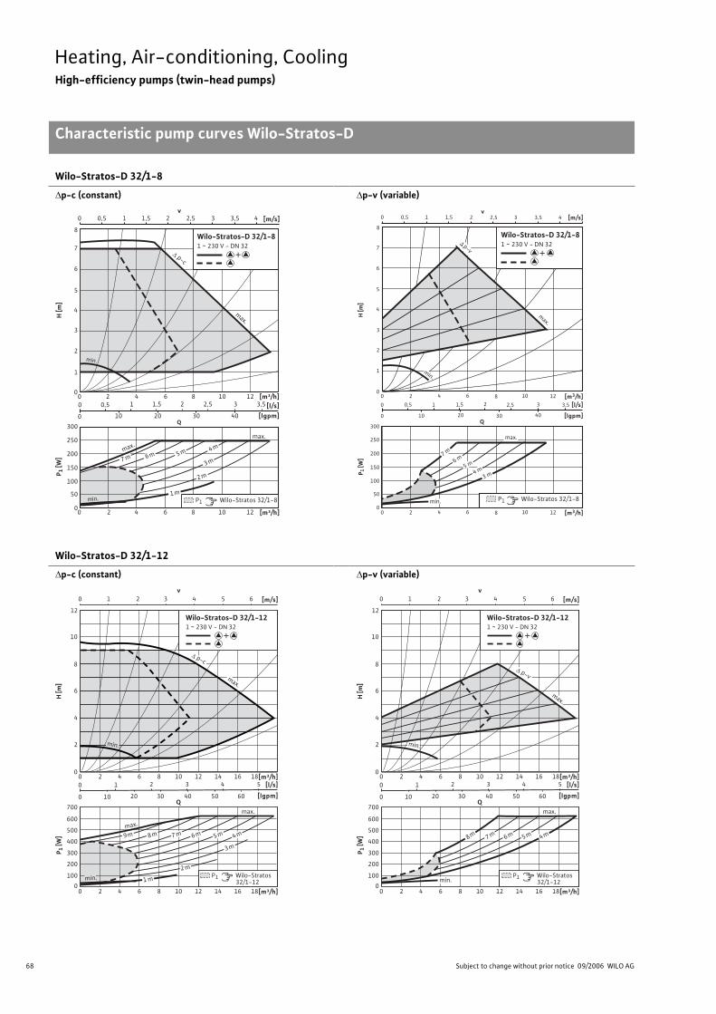
68 Subject to change without prior notice 09/2006 WILO AG
Heating, Air-conditioning, CoolingHigh-efficiency pumps (twin-head pumps)
Characteristic pump curves Wilo-Stratos-D
Wilo-Stratos-D 32/1-8
p-c (constant) p-v (variable)
Wilo-Stratos-D 32/1-12
p-c (constant) p-v (variable)
Q
max.
max.
min.
min.
v0 0,5 1 1,5 2 2,5 3 3,5 4 [m/s]
0
2
1
3
4
6
5
7
8
H [m
]
[m³/h][l/s]
[lgpm]
1280 4 1062
1 1,5 2 2,5 3,530,50
10 20 30 400
Wilo-Stratos-D 32/1-81 ~ 230 V - DN 32
+
P1 Wilo-Stratos 32/1-8
6 m 5 m4 m
3 m
2 m
1 m
7 m
max.
p-c
P 1 [W
]
0
150
100
50
200
250
300
1280 4 1062 [m³/h]
0
4
5
7
6
8
2
1
3
H [m
]
Q
P 1 [W
]
[m3/h][l/s]
[lgpm]
12106 840 2
[m3/h]12106 840 2
2
10
32,5 3,5
3020
1,510,5
0
0
40
0
150
100
50
200
250
300
[m/s]v
210 2,51,50,5 43 3,5
max.
3 m4 m
5 m6 m
7 m
min.
min.
max.
p-v
P1 Wilo-Stratos 32/1-8
Wilo-Stratos-D 32/1-81 ~ 230 V - DN 32
+
v0 1 2 3 4 5 6 [m/s]
0
8
10
12
4
2
6
H [m
]
[m³/h][l/s]
[lgpm]
P 1 [W
]
0
300
200
100
400
500
600
700
12 16 1880 4 10 1462
12 16 1880 4 10 1462 [m³/h]
2 3 4 5
10 20 30 40 50 60
1
0
0
P1 Wilo-Stratos 32/1-12
Wilo-Stratos-D 32/1-121 ~ 230 V - DN 32
+
max.
1 m
9 m 8 m 7 m 6 m 5 m 4 m
2 m
3 m
min.
max.
p-c
max.
min.
Q
v0 1 2 3 4 5 6 [m/s]
0
8
10
12
4
2
6
H [m
]
[m³/h][l/s]
[lgpm]
P 1 [W
]
0
300
200
100
400
500
600
700
12 16 1880 4 10 1462
12 16 1880 4 10 1462 [m³/h]
2 3 4 5
10 20 30 40 50 60
1
0
0
Wilo-Stratos-D 32/1-121 ~ 230 V - DN 32
+
Q
P1 Wilo-Stratos 32/1-12
max.
min.
8 m 7 m 6 m 5 m 4 m
p-v
max.
min.
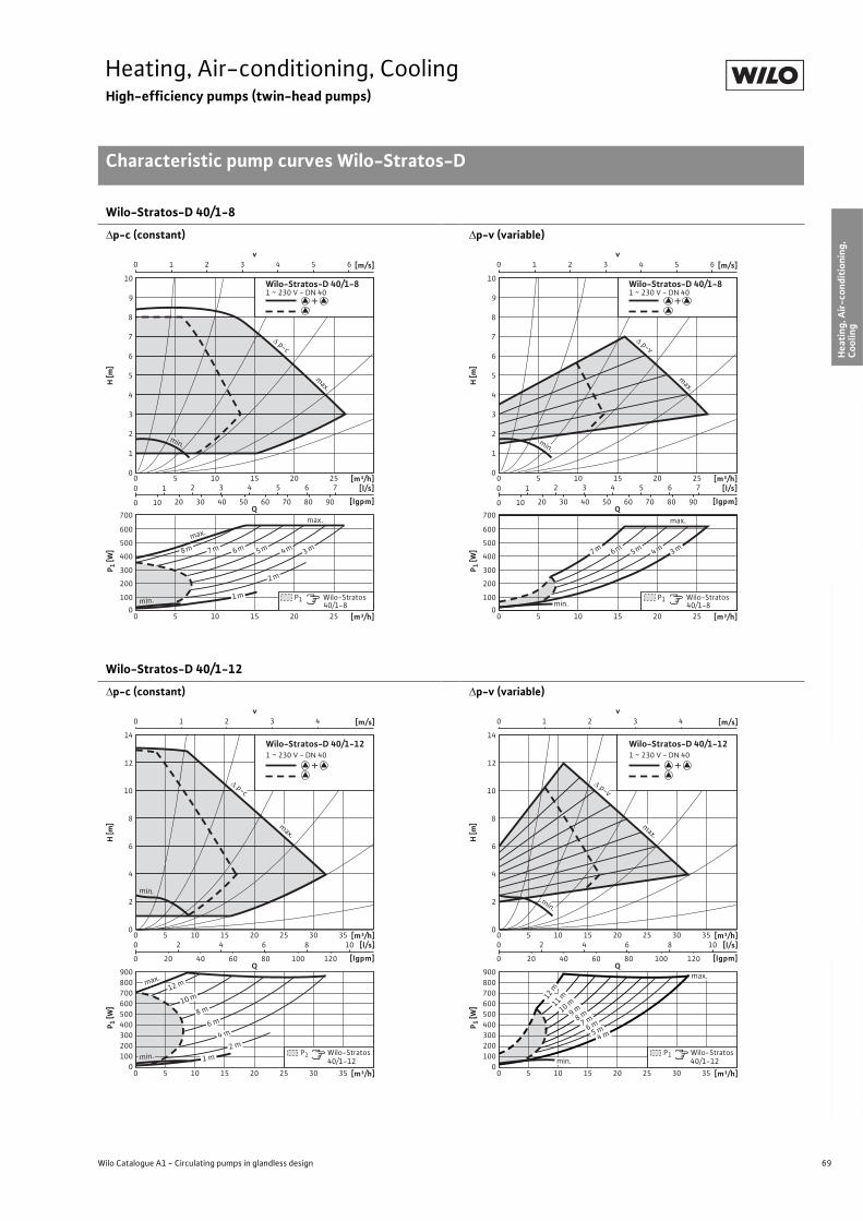
69
Heating, Air-conditioning, CoolingHigh-efficiency pumps (twin-head pumps)
Characteristic pump curves Wilo-Stratos-D
Wilo Catalogue A1 - Circulating pumps in glandless design
Hea
tin
g, A
ir-c
on
dit
ion
ing
, C
oo
ling
Po
tab
le w
ater
cir
cula
tio
nSo
lar
ther
mal
Serv
ice/
Acc
esso
ries
, Sys
tem
sSw
itch
gea
rs a
nd
Co
ntr
ol
Dev
ices
P
um
p M
anag
emen
t S y
stem
s
Wilo-Stratos-D 40/1-8
p-c (constant) p-v (variable)
Wilo-Stratos-D 40/1-12
p-c (constant) p-v (variable)
v0 1 2 3 4 5 6 [m/s]
0
8
10
4
2
6
7
9
3
1
5
H [m
]
[m³/h][l/s]
[lgpm]
P 1 [W
]
0
300
200
100
400
500
600
700
200 10 25155
2 3 4 5 6 7
10 20 30 40 50 60 70 80 90
1
0
0
[m³/h]200 10 25155
Wilo-Stratos-D 40/1-81 ~ 230 V - DN 40
+
Q
P1 Wilo-Stratos 40/1-8
max.
min.
max.
3 m
2 m
1 m
4 m5 m6 m7 m8 m
p-c
max.
min.
v0 1 2 3 4 5 6 [m/s]
0
8
10
4
2
6
7
9
3
1
5
H [m
][m³/h]
[l/s]
[lgpm]
P 1 [W
]
0
300
200
100
400
500
600
700
200 10 25155
2 3 4 5 6 7
10 20 30 40 50 60 70 80 90
1
0
0
[m³/h]200 10 25155
Wilo-Stratos-D 40/1-81 ~ 230 V - DN 40
+
Q
P1 Wilo-Stratos 40/1-8min.
3 m4 m5 m6 m7 m
max.
p-v
max.
min.
v0 1 2 3 4 [m/s]
0
8
10
14
12
4
2
6
H [m
]
[m³/h][l/s]
[lgpm]
P 1 [W
]
0
300
200
100
400
500
600
900
800
700
15 25 35300 10 205
4 6 8 10
20 40 60 80 100 120
2
0
0
[m³/h]15 25 35300 10 205
P1 Wilo-Stratos 40/1-12
Wilo-Stratos-D 40/1-121 ~ 230 V - DN 40
+
Q
min. 1 m
2 m
4 m
6 m
8 m
12 m
10 m
max.
p-c
max.
min.
v0 1 2 3 4
0
8
10
14
12
4
2
6
H [m
]P 1
[W]
0
300
200
100
400
500
600
900
800
700
15 25 35300 10 205
4 6 8 10
20 40 60 80 100 120
2
0
0
15 25 35300 10 205
P1 Wilo-Stratos 40/1-12
Wilo-Stratos-D 40/1-121 ~ 230 V - DN 40
+
Q
[m/s]
[m³/h][l/s]
[lgpm]
[m³/h]
max.
min.
5 m6 m
4 m
7 m8 m9 m10 m11 m12 m
p-v
max.
min.
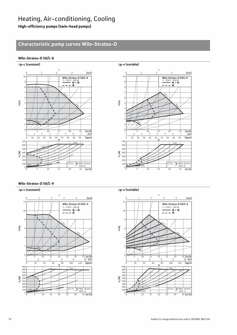
70 Subject to change without prior notice 09/2006 WILO AG
Heating, Air-conditioning, CoolingHigh-efficiency pumps (twin-head pumps)
Characteristic pump curves Wilo-Stratos-D
Wilo-Stratos-D 50/1-8
p-c (constant) p-v (variable)
Wilo-Stratos-D 50/1-9
p-c (constant) p-v (variable)
v0 1 2 3 [m/s]
0
7
8
10
9
5
4
3
2
1
6
H [m
]P 1
[W]
[m³/h][l/s]
[lgpm]
0
500
400
200
300
100
600
700
100 15 20 255
[m³/h]100 15 20 255
2 3 4 65 7
10 20 30 40 50 70 60 80 90
1
0
0
P1 Wilo-Stratos 50/1-8
Q
Wilo-Stratos-D 50/1-81 ~ 230 V - DN 50
+
max.
min.
max.
3 m
2 m
1 m
4 m5 m6 m7 m8 m
p-c
max.
min.
v0 1 2 3 [m/s]
0
7
8
10
9
5
4
3
2
1
6
H [m
]P 1
[W]
[m³/h][l/s]
[lgpm]
0
500
400
200
300
100
600
700
100 15 20 255
[m³/h]100 15 20 255
2 3 4 65 7
10 20 30 40 50 70 60 80 90
1
0
0
P1 Wilo-Stratos 50/1-8
Q
Wilo-Stratos-D 50/1-81 ~ 230 V - DN 50
+
min.
3 m4 m5 m6 m7 m
max.
p-v
max.
min.
v0 1 2 3 4 [m/s]
0
8
10
12
4
2
6
H [m
]
[m³/h][l/s]
[lgpm]
P 1 [W
]
0
300
200
100
400
500
600
900
800
700
15 25 35300 10 205
4 6 8 10
20 40 60 80 100 120
2
0
0
[m³/h]15 25 35300 10 205
P1 Wilo-Stratos 50/1-9
Wilo-Stratos-D 50/1-91 ~ 230 V - DN 50
+
Q
2 m1 m
4 m
6 m
8 m
min.
max.
p-c
max.
min.
v0 1 2 3 4 [m/s]
0
8
10
12
4
2
6
H [m
]
[m³/h][l/s]
[lgpm]
P 1 [W
]
0
300
200
100
400
500
600
900
800
700
15 25 35300 10 205
4 6 8 10
20 40 60 80 100 120
2
0
0
[m³/h]15 25 35300 10 205
P1 Wilo-Stratos 50/1-9
Wilo-Stratos-D 50/1-91 ~ 230 V - DN 50
+
Qmax.
min.
3 m4 m
5 m6 m
7 m8 m
p-v
max.
min.
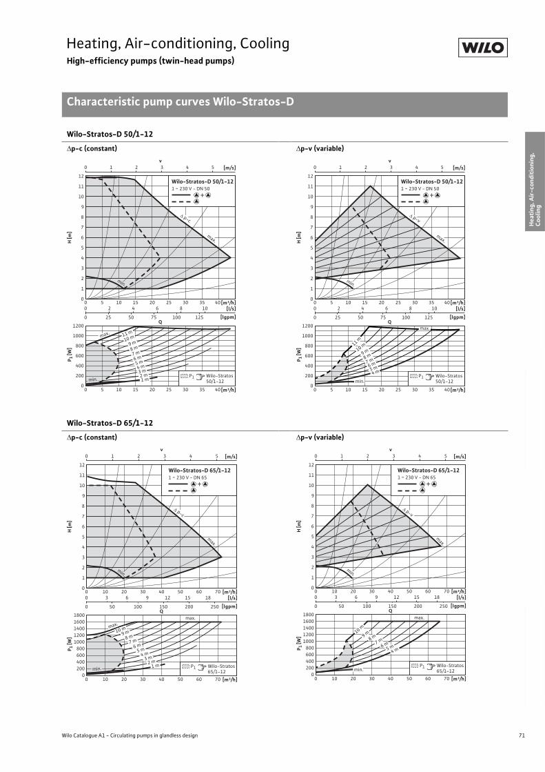
71
Heating, Air-conditioning, CoolingHigh-efficiency pumps (twin-head pumps)
Characteristic pump curves Wilo-Stratos-D
Wilo Catalogue A1 - Circulating pumps in glandless design
Hea
tin
g, A
ir-c
on
dit
ion
ing
, C
oo
ling
Po
tab
le w
ater
cir
cula
tio
nSo
lar
ther
mal
Serv
ice/
Acc
esso
ries
, Sys
tem
sSw
itch
gea
rs a
nd
Co
ntr
ol
Dev
ices
P
um
p M
anag
emen
t S y
stem
s
Wilo-Stratos-D 50/1-12
p-c (constant) p-v (variable)
Wilo-Stratos-D 65/1-12
p-c (constant) p-v (variable)
v0 1 2 3 4 5 [m/s]
0
7
8
12
11
10
9
5
4
3
2
1
6
H [m
]P 1
[W]
[m³/h][l/s]
[lgpm]
0
800
600
200
400
1000
1200
100 15 20 25 30 35 405
2 4 86 10
25 50 75 100 1250
0
[m³/h]100 15 20 25 30 35 405
P1 Wilo-Stratos 50/1-12
Q
Wilo-Stratos-D 50/1-121 ~ 230 V - DN 50
+
max.
min. 1 m2 m
3 m4 m
5 m6 m
7 m8 m
9 m10 m
11 m
p-c
max.
min.
v0 1 2 3 4 5 [m/s]
0
7
8
12
11
10
9
5
4
3
2
1
6
H [m
]P 1
[W]
[m³/h][l/s]
[lgpm]
0
800
600
200
400
1000
1200
100 15 20 25 30 35 405
2 4 86 10
25 50 75 100 1250
0
[m³/h]100 15 20 25 30 35 405
P1 Wilo-Stratos 50/1-12
Q
Wilo-Stratos-D 50/1-121 ~ 230 V - DN 50
+
min.
max.
4 m5 m
6 m7 m
8 m9 m10 m11 m
p-v
max.
min.
v0 1 2 3 4 5 [m/s]
0
7
8
12
11
10
9
5
4
3
2
1
6
H [m
]P 1
[W]
[m³/h][l/s]
[lgpm]
0
800
600
200
400
1000
1200
1400
1600
1800
200 30 40 50 60 7010
3 6 9 1512 18
50 100 150 200 2500
0
[m³/h]200 30 40 50 60 7010
P1 Wilo-Stratos 65/1-12
Q
Wilo-Stratos-D 65/1-121 ~ 230 V - DN 65
+
max.
max.
2 m3 m
4 m5 m
6 m
1 m
7 m8 m
9 m10 m
min.
p-c
max.
min.
v0 1 2 3 4 5 [m/s]
0
7
8
12
11
10
9
5
4
3
2
1
6
H [m
]P 1
[W]
[m³/h][l/s]
[lgpm]
0
800
600
200
400
1000
1200
1400
1600
1800
200 30 40 50 60 7010
3 6 9 1512 18
50 100 150 200 2500
0
[m³/h]200 30 40 50 60 7010
P1 Wilo-Stratos 65/1-12
Q
Wilo-Stratos-D 65/1-121 ~ 230 V - DN 65
+
max.
4 m5 m6 m7 m8 m9 m10 m
min.
p-v
max.
min.
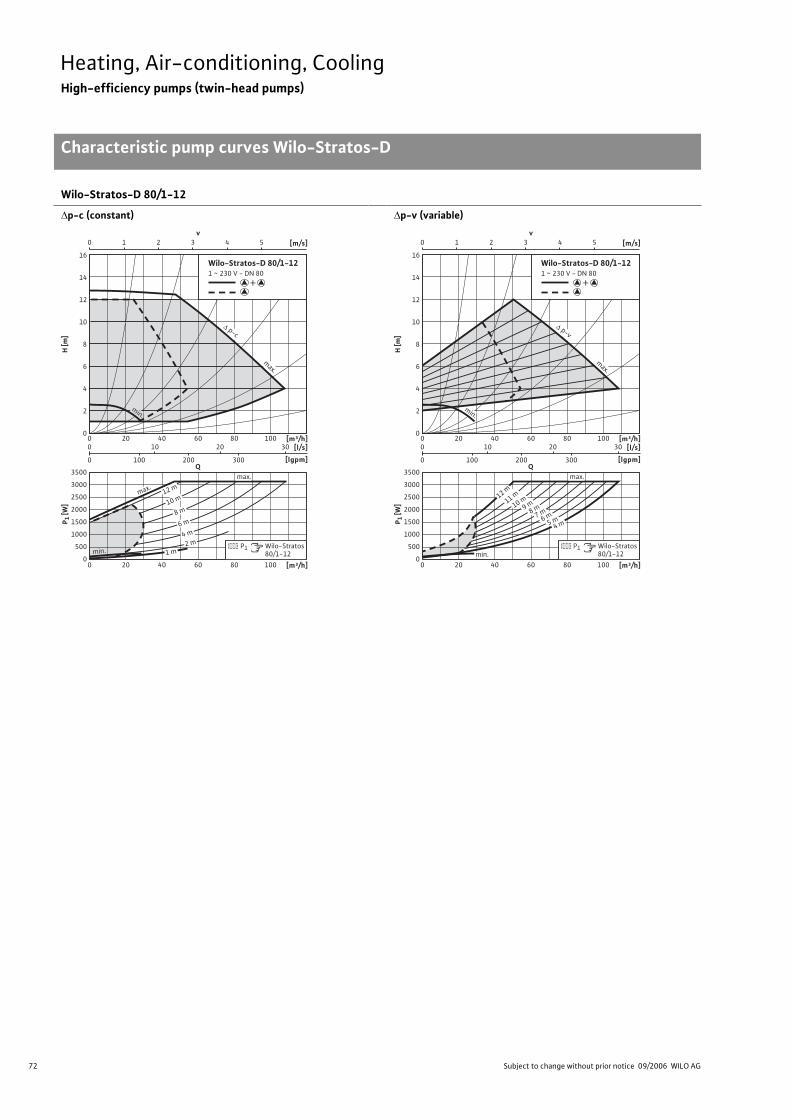
72 Subject to change without prior notice 09/2006 WILO AG
Heating, Air-conditioning, CoolingHigh-efficiency pumps (twin-head pumps)
Characteristic pump curves Wilo-Stratos-D
Wilo-Stratos-D 80/1-12
p-c (constant) p-v (variable)
v0 1 2 3 4 5 [m/s]
0
8
14
12
10
4
2
6
H [m
]P 1
[W]
[m³/h][l/s]
[lgpm]
0
1000
500
1500
2000
2500
3000
3500
400 60 80 10020
10 20 30
100 200 3000
0
[m³/h]400 60 80 10020
P1 Wilo-Stratos 80/1-12
Q
Wilo-Stratos-D 80/1-121 ~ 230 V - DN 80
+
16
min.
max.
max.
2 m4 m
6 m
1 m
8 m10 m
12 m
p-c
max.
min.
v0 1 2 3 4 5 [m/s]
0
8
14
12
10
4
2
6
H [m
]P 1
[W]
[m³/h][l/s]
[lgpm]
0
1000
500
1500
2000
2500
3000
3500
400 60 80 10020
10 20 30
100 200 3000
0
[m³/h]400 60 80 10020
P1 Wilo-Stratos 80/1-12
Q
Wilo-Stratos-D 80/1-121 ~ 230 V - DN 80
+
16
max.
min.
4 m5 m6 m7 m8 m9 m10 m11 m12 m
p-v
max.
min.
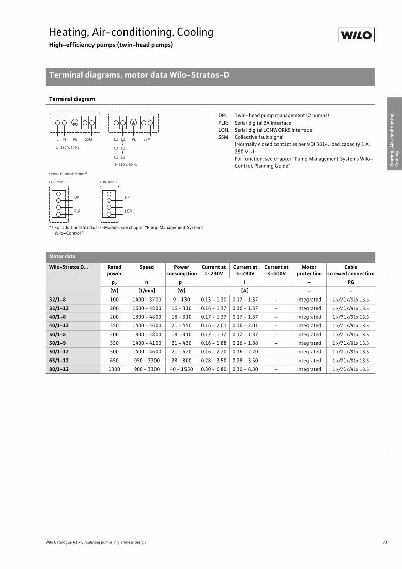
73
Heating, Air-conditioning, CoolingHigh-efficiency pumps (twin-head pumps)
Terminal diagrams, motor data Wilo-Stratos-D
Wilo Catalogue A1 - Circulating pumps in glandless design
Hea
tin
g, A
ir-c
on
dit
ion
ing
, C
oo
ling
Po
tab
le w
ater
cir
cula
tio
nSo
lar
ther
mal
Serv
ice/
Acc
esso
ries
, Sys
tem
sSw
itch
gea
rs a
nd
Co
ntr
ol
Dev
ices
P
um
p M
anag
emen
t S y
stem
s
Terminal diagram
*) For additional Stratos IF-Module, see chapter “Pump Management Systems Wilo-Control ”
DP: Twin-head pump management (2 pumps)
PLR: Serial digital BA interface
LON: Serial digital LONWORKS interface
SSM Collective fault signal
(Normally closed contact as per VDI 3814, load capacity 1 A,
250 V ~)
For function, see chapter “Pump Management Systems Wilo-
Control, Planning Guide”
Motor data
Wilo-Stratos D... Rated power
Speed Power consumption
Current at1~230V
Current at3~230V
Current at3~400V
Motor protection
Cablescrewed connection
p2 n p1 I - PG
[W] [1/min] [W] [A] - -
32/1-8 100 1400 - 3700 9 - 130 0.13 - 1.20 0.17 - 1.37 – integrated 1 x/71x/91x 13.5
32/1-12 200 1600 - 4800 16 - 310 0.16 - 1.37 0.16 - 1.37 – integrated 1 x/71x/91x 13.5
40/1-8 200 1800 - 4800 18 - 310 0.17 - 1.37 0.17 - 1.37 – integrated 1 x/71x/91x 13.5
40/1-12 350 1400 - 4600 21 - 450 0.16 - 2.01 0.16 - 2.01 – integrated 1 x/71x/91x 13.5
50/1-8 200 1800 - 4800 18 - 310 0.17 - 1.37 0.17 - 1.37 – integrated 1 x/71x/91x 13.5
50/1-9 350 1400 - 4100 21 - 430 0.16 - 1.88 0.16 - 1.88 – integrated 1 x/71x/91x 13.5
50/1-12 500 1400 - 4600 21 - 620 0.16 - 2.70 0.16 - 2.70 – integrated 1 x/71x/91x 13.5
65/1-12 650 950 - 3300 38 - 800 0.28 - 3.50 0.28 - 3.50 – integrated 1 x/71x/91x 13.5
80/1-12 1300 900 - 3300 40 - 1550 0.30 - 6.80 0.30 - 6.80 – integrated 1 x/71x/91x 13.5
L N PE SSM L1 L3
L2 L3
L1 L2
PE SSM
DP
PLR
DP
LON
Option: IF-Module Stratos *)
PLR-modul LON-modul
1~ 230 V, 50 Hz
3~ 230 V, 50 Hz
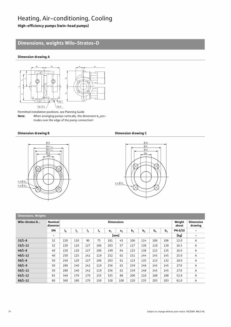
74 Subject to change without prior notice 09/2006 WILO AG
Heating, Air-conditioning, CoolingHigh-efficiency pumps (twin-head pumps)
Dimensions, weights Wilo-Stratos-D
Dimension drawing A
Permitted installation positions, see Planning Guide
Note: When arranging pumps vertically, the dimension b5 pro-
trudes over the edge of the pump connection!
Dimension drawing B Dimension drawing C
Dimensions, Weights
Wilo-Stratos D... Nominal diameter
Dimensions Weight about
Dimension drawing
DN l0 l1 l3 l4 a1 a2 b1 b2 b4 b5 PN 6/10 -
- [mm] [kg] -
32/1-8 32 220 110 90 75 181 43 106 114 106 106 12.0 A
32/1-12 32 220 110 127 106 203 57 117 130 110 130 16.5 A
40/1-8 40 220 110 127 106 199 64 125 138 115 135 16.6 A
40/1-12 40 250 125 142 119 252 62 151 144 145 145 25.0 A
50/1-8 50 240 120 127 106 203 61 123 135 113 132 18.0 A
50/1-9 50 280 140 142 119 256 62 159 148 145 145 27.0 A
50/1-12 50 280 140 142 119 256 62 159 148 145 145 27.0 A
65/1-12 65 340 170 170 155 325 88 200 210 188 188 52.8 A
80/1-12 80 360 180 170 150 328 100 220 235 203 203 61.0 A
Pg 7
Pg 9Pg 13,5
a1b 2
b 1b5b4
l 0l 3
l 4
a2
l 1
Ø D
n x Ø d
Ø k
DN
L2
Ø k Ø d
L 1
1
n x Ø d 2
n x Ø d
Ø D Ø k
DN
Ø d
L
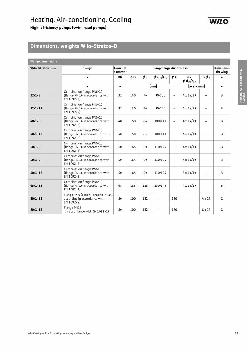
75
Heating, Air-conditioning, CoolingHigh-efficiency pumps (twin-head pumps)
Dimensions, weights Wilo-Stratos-D
Wilo Catalogue A1 - Circulating pumps in glandless design
Hea
tin
g, A
ir-c
on
dit
ion
ing
, C
oo
ling
Po
tab
le w
ater
cir
cula
tio
nSo
lar
ther
mal
Serv
ice/
Acc
esso
ries
, Sys
tem
sSw
itch
gea
rs a
nd
Co
ntr
ol
Dev
ices
P
um
p M
anag
emen
t S y
stem
s
Flange dimensions
Wilo-Stratos-D ... Flange Nominal diameter
Pump flange dimensions Dimension drawing
- DN Ø D Ø d Ø KL1/KL2 Ø k n xØ dL1/dL2
n x Ø dL -
- - [mm] [pcs. x mm] -
32/1-8Combination flange PN6/10(flange PN 16 in accordance with EN 1092-2)
32 140 76 90/100 – 4 x 14/19 – B
32/1-12Combination flange PN6/10(flange PN 16 in accordance with EN 1092-2)
32 140 76 90/100 – 4 x 14/19 – B
40/1-8Combination flange PN6/10(flange PN 16 in accordance with EN 1092-2)
40 150 84 100/110 – 4 x 14/19 – B
40/1-12Combination flange PN6/10(flange PN 16 in accordance with EN 1092-2)
40 150 84 100/110 – 4 x 14/19 – B
50/1-8Combination flange PN6/10(flange PN 16 in accordance with EN 1092-2)
50 165 99 110/125 – 4 x 14/19 – B
50/1-9Combination flange PN6/10(flange PN 16 in accordance with EN 1092-2)
50 165 99 110/125 – 4 x 14/19 – B
50/1-12Combination flange PN6/10(flange PN 16 in accordance with EN 1092-2)
50 165 99 110/125 – 4 x 14/19 – B
65/1-12Combination flange PN6/10(flange PN 16 in accordance with EN 1092-2)
65 185 118 130/145 – 4 x 14/19 – B
80/1-12Flange PN 6 (dimensioned to PN 16, according in accordance with EN 1092-2)
80 200 132 – 150 – 4 x 19 C
80/1-12Flange PN16 (in accordance with EN 1092-2)
80 200 132 – 160 – 8 x 19 C
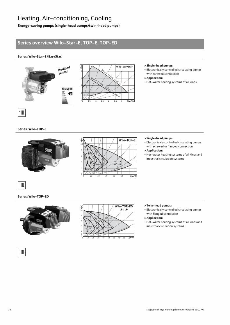
76 Subject to change without prior notice 09/2006 WILO AG
Heating, Air-conditioning, CoolingEnergy-saving pumps (single-head pumps/twin-head pumps)
Series overview Wilo-Star-E, TOP-E, TOP-ED
Series: Wilo-Star-E (EasyStar)
> Single-head pumps:• Electronically controlled circulating pumps
with screwed connection
> Application:• Hot-water heating systems of all kinds
Series: Wilo-TOP-E
> Single-head pumps:• Electronically controlled circulating pumps
with screwed or flanged connection
> Application:• Hot-water heating systems of all kinds and
industrial circulation systems
Series: Wilo-TOP-ED
> Twin-head pumps:• Electronically controlled circulating pumps
with flanged connection
> Application:• Hot-water heating systems of all kinds and
industrial circulation systems
Modified
series!
Q[m³/h]
Wilo-EasyStar
H[m
]
00 0,5 1 1,5 2 32,5
1
2
3
4Star-E 15 (25, 30)/1-5
Star-E 15 (25, 30)/1-3
0 10 20 30 40 50 0 1
2
4
6
8
10
Wilo-TOP-E
80/1-10100/1-10
40/1-4
50/1-7
30/1-10 40/1-10
50/1-10
50/1-6
65/1-10
25
(30
)/1-7
Q[m3/h]
H[m
]
0 10 20 30 40 50 60 70 80 0 1
2
4
6
8
10
32/1-7
40/1-750/1-6
80/1-10
65/1-10
40/1-10 50/1-10
50/1-7
Wilo-TOP-ED
Q[m3/h]
H[m
]
+
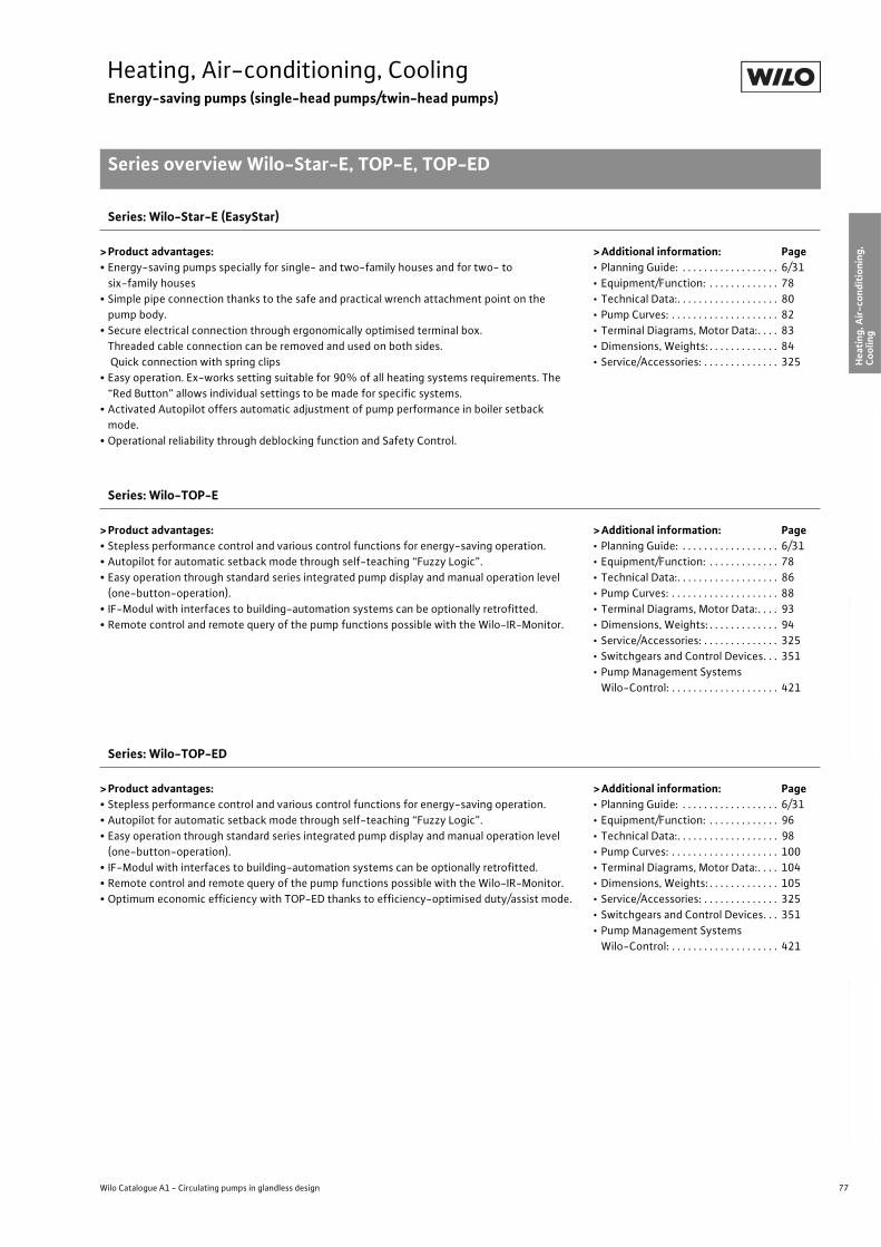
77
Heating, Air-conditioning, CoolingEnergy-saving pumps (single-head pumps/twin-head pumps)
Series overview Wilo-Star-E, TOP-E, TOP-ED
Wilo Catalogue A1 - Circulating pumps in glandless design
Hea
tin
g, A
ir-c
on
dit
ion
ing
, C
oo
ling
Po
tab
le w
ater
cir
cula
tio
nSo
lar
ther
mal
Serv
ice/
Acc
esso
ries
, Sys
tem
sSw
itch
gea
rs a
nd
Co
ntr
ol
Dev
ices
P
um
p M
anag
emen
t S y
stem
s
Series: Wilo-Star-E (EasyStar)
> Product advantages:• Energy-saving pumps specially for single- and two-family houses and for two- to
six-family houses
• Simple pipe connection thanks to the safe and practical wrench attachment point on the
pump body.
• Secure electrical connection through ergonomically optimised terminal box.
Threaded cable connection can be removed and used on both sides.
Quick connection with spring clips
• Easy operation. Ex-works setting suitable for 90% of all heating systems requirements. The
“Red Button” allows individual settings to be made for specific systems.
• Activated Autopilot offers automatic adjustment of pump performance in boiler setback
mode.
• Operational reliability through deblocking function and Safety Control.
>Additional information: Page• Planning Guide: . . . . . . . . . . . . . . . . . . 6/31
• Equipment/Function: . . . . . . . . . . . . . 78
• Technical Data:. . . . . . . . . . . . . . . . . . . 80
• Pump Curves: . . . . . . . . . . . . . . . . . . . . 82
• Terminal Diagrams, Motor Data:. . . . 83
• Dimensions, Weights: . . . . . . . . . . . . . 84
• Service/Accessories: . . . . . . . . . . . . . . 325
Series: Wilo-TOP-E
> Product advantages:• Stepless performance control and various control functions for energy-saving operation.
• Autopilot for automatic setback mode through self-teaching “Fuzzy Logic”.
• Easy operation through standard series integrated pump display and manual operation level
(one-button-operation).
• IF-Modul with interfaces to building-automation systems can be optionally retrofitted.
• Remote control and remote query of the pump functions possible with the Wilo-IR-Monitor.
>Additional information: Page• Planning Guide: . . . . . . . . . . . . . . . . . . 6/31
• Equipment/Function: . . . . . . . . . . . . . 78
• Technical Data:. . . . . . . . . . . . . . . . . . . 86
• Pump Curves: . . . . . . . . . . . . . . . . . . . . 88
• Terminal Diagrams, Motor Data:. . . . 93
• Dimensions, Weights: . . . . . . . . . . . . . 94
• Service/Accessories: . . . . . . . . . . . . . . 325
• Switchgears and Control Devices. . . 351
• Pump Management Systems
Wilo-Control: . . . . . . . . . . . . . . . . . . . . 421
Series: Wilo-TOP-ED
> Product advantages:• Stepless performance control and various control functions for energy-saving operation.
• Autopilot for automatic setback mode through self-teaching “Fuzzy Logic”.
• Easy operation through standard series integrated pump display and manual operation level
(one-button-operation).
• IF-Modul with interfaces to building-automation systems can be optionally retrofitted.
• Remote control and remote query of the pump functions possible with the Wilo-IR-Monitor.
• Optimum economic efficiency with TOP-ED thanks to efficiency-optimised duty/assist mode.
>Additional information: Page• Planning Guide: . . . . . . . . . . . . . . . . . . 6/31
• Equipment/Function: . . . . . . . . . . . . . 96
• Technical Data:. . . . . . . . . . . . . . . . . . . 98
• Pump Curves: . . . . . . . . . . . . . . . . . . . . 100
• Terminal Diagrams, Motor Data:. . . . 104
• Dimensions, Weights: . . . . . . . . . . . . . 105
• Service/Accessories: . . . . . . . . . . . . . . 325
• Switchgears and Control Devices. . . 351
• Pump Management Systems
Wilo-Control: . . . . . . . . . . . . . . . . . . . . 421
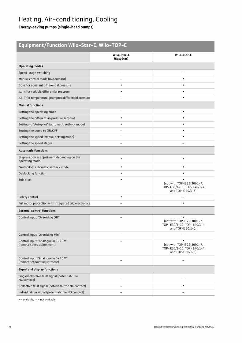
78 Subject to change without prior notice 09/2006 WILO AG
Heating, Air-conditioning, CoolingEnergy-saving pumps (single-head pumps)
Equipment/Function Wilo-Star-E, Wilo-TOP-E
Wilo-Star-E(EasyStar)
Wilo-TOP-E
Operating modes
Speed-stage switching – –
Manual control mode (n=constant) – •
p-c for constant differential pressure • •
p-v for variable differential pressure • •
p-T for temperature-prompted differential pressure – •
Manual functions
Setting the operating mode – •
Setting the differential-pressure setpoint • •
Setting to “Autopilot” (automatic setback mode) • •
Setting the pump to ON/OFF – •
Setting the speed (manual setting mode) – •
Setting the speed stages – –
Automatic functions
Stepless power adjustment depending on the operating mode
• •
“Autopilot” automatic setback mode • •
Deblocking function • •
Soft start • •(not with TOP-E 25(30)/1-7,
TOP- E30/1-10, TOP- E40/1-4 and TOP-E 50/1-6)
Safety control • –
Full motor protection with integrated trip electronics – •
External control functions
Control input “Overriding Off” – •(not with TOP-E 25(30)/1-7,
TOP- E30/1-10, TOP- E40/1-4 and TOP-E 50/1-6)
Control input “Overriding Min” – –
Control input “Analogue in 0- 10 V” (remote speed adjustment)
– •(not with TOP-E 25(30)/1-7,
TOP- E30/1-10, TOP- E40/1-4 and TOP-E 50/1-6)
Control input “Analogue in 0- 10 V” (remote setpoint adjustment)
– –
Signal and display functions
Single/collective fault signal (potential-free NC contact)
– –
Collective fault signal (potential-free NC contact) – •
Individual run signal (potential-free NO contact) – –
• = available, – = not available
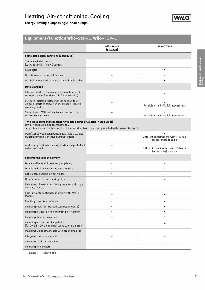
79
Heating, Air-conditioning, CoolingEnergy-saving pumps (single-head pumps)
Equipment/Function Wilo-Star-E, Wilo-TOP-E
Wilo Catalogue A1 - Circulating pumps in glandless design
Hea
tin
g, A
ir-c
on
dit
ion
ing
, C
oo
ling
Po
tab
le w
ater
cir
cula
tio
nSo
lar
ther
mal
Serv
ice/
Acc
esso
ries
, Sys
tem
sSw
itch
gea
rs a
nd
Co
ntr
ol
Dev
ices
P
um
p M
anag
emen
t S y
stem
s
Signal and display functions (Continued)
Thermal winding contact (WSK, potential-free NC contact)
– –
Fault light – •
Direction-of-rotation telltale lamp – –
LC display for showing pump data and fault codes – •
Data exchange
Infrared interface for wireless data exchange with IR-Monitor (see function table for IR-Monitor)
– •
PLR serial digital interface for connection to BA via Wilo interface converter or company-specific coupling modules
– •Possible with IF-Modul (accessories)
Serial digital LON interface for connection to a LONWORKS network
– •Possible with IF-Modul (accessories)
Twin-head pump management (twin-head pump or 2 single-head pumps)(Twin-head pump management with 2 single-head pumps only possible if the equivalent twin-head pump is listed in the Wilo catalogue)
Main/standby operation (automatic fault-actuated switchover/time-sensitive pump alteration)
– •Different combinations with IF-Modul
(accessories) possible
Addition operation (efficiency-optimised peak-load cut-in and out)
– •Different combinations with IF-Modul
(accessories) possible
Equipment/Scope of delivery
Wrench attachment point on pump body • –
Double switchover valve in pump housing – –
Cable entry possible on both sides • –
Quick connection with spring clips • –
Integrated air extraction fitting for automatic rapid ventilator Rp 3/8
– –
Plug-in slot for optional expansion with Wilo-IF-Moduls
– •
Blocking current-proof motor • –
Including seals for threaded connection (loose) • •
Including installation and operating instructions • •
Including thermal insulation – •
Including washers for flange bolts(for DN 32 - DN 65 nominal connection diameters)
– •
Including 1.8 m power cable with grounding plug – –
Integrated non-return valve – –
Integrated ball shutoff valve – –
Including time switch – –
Wilo-Star-E(EasyStar)
Wilo-TOP-E
• = available, – = not available
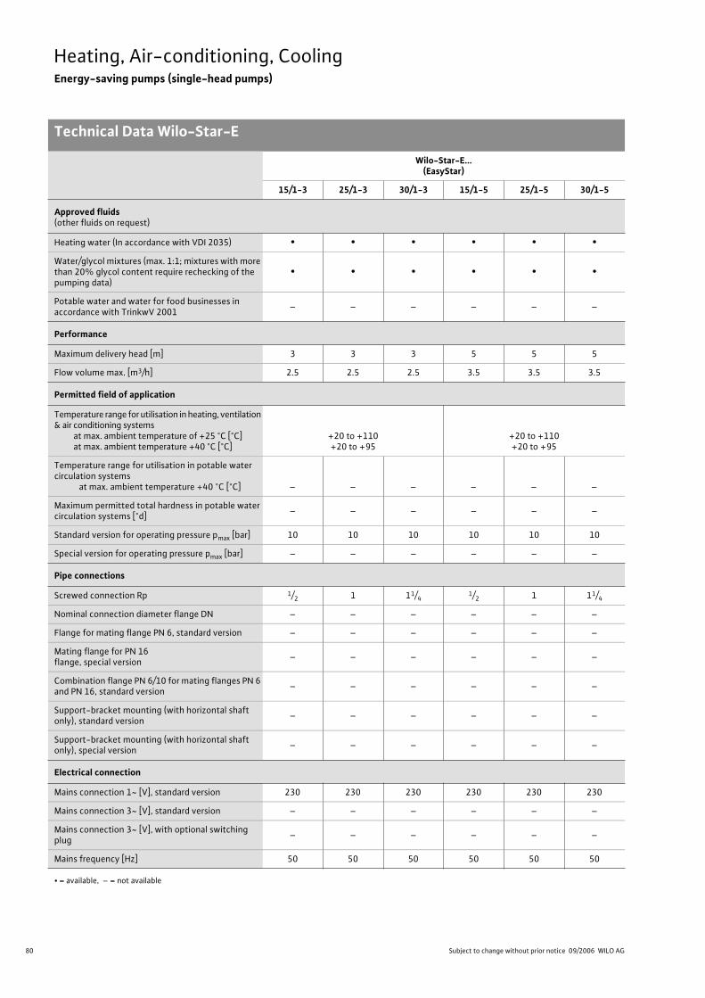
80 Subject to change without prior notice 09/2006 WILO AG
Heating, Air-conditioning, CoolingEnergy-saving pumps (single-head pumps)
Technical Data Wilo-Star-E
Wilo-Star-E...(EasyStar)
15/1-3 25/1-3 30/1-3 15/1-5 25/1-5 30/1-5
Approved fluids(other fluids on request)
Heating water (In accordance with VDI 2035) • • • • • •
Water/glycol mixtures (max. 1:1; mixtures with more than 20% glycol content require rechecking of the pumping data)
• • • • • •
Potable water and water for food businesses in accordance with TrinkwV 2001
– – – – – –
Performance
Maximum delivery head [m] 3 3 3 5 5 5
Flow volume max. [m3/h] 2.5 2.5 2.5 3.5 3.5 3.5
Permitted field of application
Temperature range for utilisation in heating, ventilation & air conditioning systems
at max. ambient temperature of +25 °C [°C]at max. ambient temperature +40 °C [°C]
+20 to +110+20 to +95
+20 to +110+20 to +95
Temperature range for utilisation in potable water circulation systems at max. ambient temperature +40 °C [°C] – – – – – –
Maximum permitted total hardness in potable water circulation systems [°d]
– – – – – –
Standard version for operating pressure pmax [bar] 10 10 10 10 10 10
Special version for operating pressure pmax [bar] – – – – – –
Pipe connections
Screwed connection Rp 1/2 1 11/41/2 1 11/4
Nominal connection diameter flange DN – – – – – –
Flange for mating flange PN 6, standard version – – – – – –
Mating flange for PN 16 flange, special version
– – – – – –
Combination flange PN 6/10 for mating flanges PN 6 and PN 16, standard version
– – – – – –
Support-bracket mounting (with horizontal shaft only), standard version
– – – – – –
Support-bracket mounting (with horizontal shaft only), special version
– – – – – –
Electrical connection
Mains connection 1~ [V], standard version 230 230 230 230 230 230
Mains connection 3~ [V], standard version – – – – – –
Mains connection 3~ [V], with optional switching plug
– – – – – –
Mains frequency [Hz] 50 50 50 50 50 50
• = available, – = not available

81
Heating, Air-conditioning, CoolingEnergy-saving pumps (single-head pumps)
Technical Data Wilo-Star-E
Wilo Catalogue A1 - Circulating pumps in glandless design
Hea
tin
g, A
ir-c
on
dit
ion
ing
, C
oo
ling
Po
tab
le w
ater
cir
cula
tio
nSo
lar
ther
mal
Serv
ice/
Acc
esso
ries
, Sys
tem
sSw
itch
gea
rs a
nd
Co
ntr
ol
Dev
ices
P
um
p M
anag
emen
t S y
stem
s
Motor/electronics
Electromagnetic compatibility EN 61000-6-3
Emitted interference EN 61000-6-3
Immunity to interference EN 61000-6-2
Power electronics Pulse-pack control
Protection class IP 42 IP 42 IP 42 IP 42 IP 42 IP 42
Insulation class F F F F F F
Materials
Pump housing Grey cast iron (EN-GJL-200)
Impeller Plastic (PP -%40 GF)
Shaft Stainless steel (X40 Cr13)
Bearing Metal-impregnated carbon
Minimum suction head at suction branch [m]for the prevention of cavitation at water delivery temperature
50 °C 0.5 0.5 0.5 0.5 0.5 0.5
95 °C 3 3 3 3 3 3
110 °C 10 10 10 10 10 10
Wilo-Star-E...(EasyStar)
15/1-3 25/1-3 30/1-3 15/1-5 25/1-5 30/1-5
• = available, – = not available
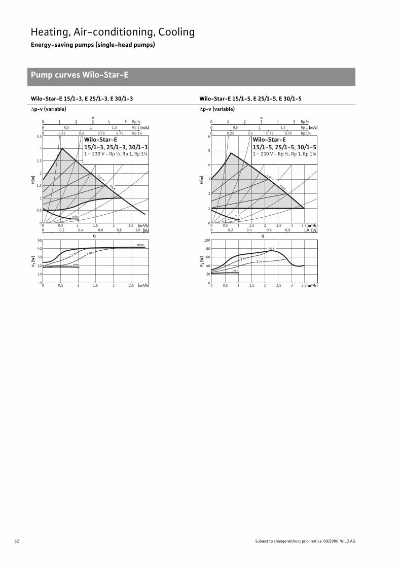
82 Subject to change without prior notice 09/2006 WILO AG
Heating, Air-conditioning, CoolingEnergy-saving pumps (single-head pumps)
Pump curves Wilo-Star-E
Wilo-Star-E 15/1-3, E 25/1-3, E 30/1-3 Wilo-Star-E 15/1-5, E 25/1-5, E 30/1-5
p-v (variable) p-v (variable)
Q
Rp ½
Rp 1
Rp 1¼
0 31 2
0
0
0,5
0,25 0,5 0,75 0,75
v
1 1,5
4 5
[m/s]
00 0,5
0 0,2 0,4 0,6 0,8 1,0
1,51 2 2,5
2
1
0,5
1,5
0
20
10
30
40
50
3
2,5
3,5
H[m
]
[m³/h]
0 0,5 1,51 2 2,5 [m³/h]
P 1 [W
]
p-v
[l/s]
Wilo-Star-E15/1-3, 25/1-3, 30/1-31 ~ 230 V - Rp ½, Rp 1, Rp 1¼
max.
min.
3 m 2 m
min.
max.
Q
Rp ½
Rp 1
Rp 1¼
0 31 2
0
0
0,5
0,25 0,5 0,75 0,75
v
1 1,5
4 5
Wilo-Star-E15/1-5, 25/1-5, 30/1-51 ~ 230 V - Rp ½, Rp 1, Rp 1¼
[m/s]
00 0,5
0 0,2 0,4 0,6 0,8 1,0
1,51 2 2,5 3,53
4
2
1
3
0
40
20
60
80
100
6
5
H[m
]
[m³/h]
0 0,5 1,51 2 2,5 3,53 [m³/h]
P 1 [W
]
p-v
max.
min.
min.
max.
[l/s]
3 m2 m
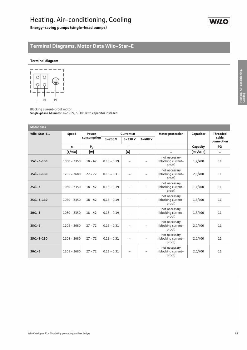
83
Heating, Air-conditioning, CoolingEnergy-saving pumps (single-head pumps)
Terminal Diagrams, Motor Data Wilo-Star-E
Wilo Catalogue A1 - Circulating pumps in glandless design
Hea
tin
g, A
ir-c
on
dit
ion
ing
, C
oo
ling
Po
tab
le w
ater
cir
cula
tio
nSo
lar
ther
mal
Serv
ice/
Acc
esso
ries
, Sys
tem
sSw
itch
gea
rs a
nd
Co
ntr
ol
Dev
ices
P
um
p M
anag
emen
t S y
stem
s
Terminal diagram
Blocking current-proof motorSingle-phase AC motor 1~230 V, 50 Hz, with capacitor installed
Motor data
Wilo-Star-E... Speed Power consumption
Current at Motor protection Capacitor Threaded cable
connection1~230 V 3~230 V 3~400 V
n P1 I – Capacity PG
[1/min] [W] [A] – [mF/VDB] –
15/1-3-130 1060 - 2350 18 - 42 0.13 - 0.19 – –not necessary
(blocking current-proof)
1,7/400 11
15/1-5-130 1205 - 2680 27 - 72 0.15 - 0.31 – –not necessary
(blocking current-proof)
2,0/400 11
25/1-3 1060 - 2350 18 - 42 0.13 - 0.19 – –not necessary
(blocking current-proof)
1,7/400 11
25/1-3-130 1060 - 2350 18 - 42 0.13 - 0,19 – –not necessary
(blocking current-proof)
1,7/400 11
30/1-3 1060 - 2350 18 - 42 0.13 - 0.19 – –not necessary
(blocking current-proof)
1,7/400 11
25/1-5 1205 - 2680 27 - 72 0.15 - 0.31 – –not necessary
(blocking current-proof)
2,0/400 11
25/1-5-130 1205 - 2680 27 - 72 0.15 - 0.31 – –not necessary
(blocking current-proof)
2,0/400 11
30/1-5 1205 - 2680 27 - 72 0.15 - 0.31 – –not necessary
(blocking current-proof)
2,0/400 11
L N PE
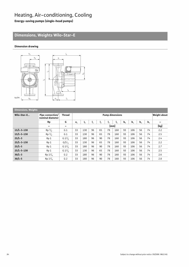
84 Subject to change without prior notice 09/2006 WILO AG
Heating, Air-conditioning, CoolingEnergy-saving pumps (single-head pumps)
Dimensions, Weights Wilo-Star-E
Dimension drawing
Dimensions, Weights
Wilo-Star-E... Pipe connection/nominal diameter
Thread Pump dimensions Weight about
Rp G a1 I0 l1 l2 l3 l4 b0 b1 b2 b3 –
– – [mm] [kg]
15/1-3-130 Rp 1/2 G 1 33 130 96 65 78 160 93 106 56 74 2.2
15/1-5-130 Rp 1/2 G 1 33 130 96 65 78 160 93 106 56 74 2.5
25/1-3 Rp 1 G 11/2 33 180 96 90 78 160 93 106 56 74 2.4
25/1-3-130 Rp 1 G/112 33 130 96 65 78 160 93 106 56 74 2.2
25/1-5 Rp 1 G 11/2 33 180 96 90 78 160 93 106 56 74 2.7
25/1-5-130 Rp 1 G 11/2 33 130 96 65 78 160 93 106 56 74 2.5
30/1-3 Rp 11/4 G 2 33 180 96 90 78 160 93 106 56 74 2.6
30/1-5 Rp 11/4 G 2 33 180 96 90 78 160 93 106 56 74 2.8
G
b 3
l 0
l 2
b0
b1
b2
a1 l1
l3
l4
Rp/DN
85
Heating, Air-conditioning, CoolingEnergy-saving pumps (single-head pumps)
Wilo Catalogue A1 - Circulating pumps in glandless design
Hea
tin
g, A
ir-c
on
dit
ion
ing
, C
oo
ling
Po
tab
le w
ater
cir
cula
tio
nSo
lar
ther
mal
Serv
ice/
Acc
esso
ries
, Sys
tem
sSw
itch
gea
rs a
nd
Co
ntr
ol
Dev
ices
P
um
p M
anag
emen
t S y
stem
s
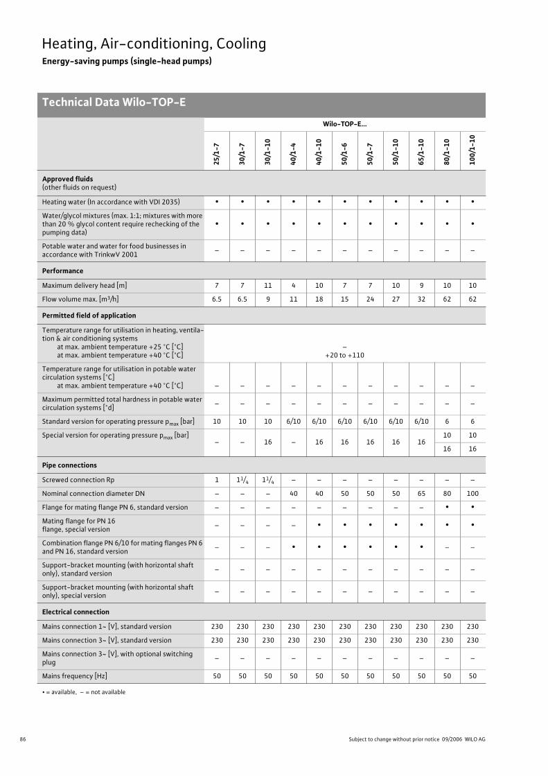
86 Subject to change without prior notice 09/2006 WILO AG
Heating, Air-conditioning, CoolingEnergy-saving pumps (single-head pumps)
Technical Data Wilo-TOP-E
Wilo-TOP-E...
25
/1-7
30
/1-7
30
/1-1
0
40
/1-4
40
/1-1
0
50
/1-6
50
/1-7
50
/1-1
0
65
/1-1
0
80
/1-1
0
10
0/1
-10
Approved fluids(other fluids on request)
Heating water (In accordance with VDI 2035) • • • • • • • • • • •
Water/glycol mixtures (max. 1:1; mixtures with more than 20 % glycol content require rechecking of the pumping data)
• • • • • • • • • • •
Potable water and water for food businesses in accordance with TrinkwV 2001
– – – – – – – – – – –
Performance
Maximum delivery head [m] 7 7 11 4 10 7 7 10 9 10 10
Flow volume max. [m3/h] 6.5 6.5 9 11 18 15 24 27 32 62 62
Permitted field of application
Temperature range for utilisation in heating, ventila-tion & air conditioning systems
at max. ambient temperature +25 °C [°C]at max. ambient temperature +40 °C [°C]
–+20 to +110
Temperature range for utilisation in potable water circulation systems [°C]
at max. ambient temperature +40 °C [°C] – – – – – – – – – – –
Maximum permitted total hardness in potable water circulation systems [°d]
– – – – – – – – – – –
Standard version for operating pressure pmax [bar] 10 10 10 6/10 6/10 6/10 6/10 6/10 6/10 6 6
Special version for operating pressure pmax [bar]– – 16 – 16 16 16 16 16
10 10
16 16
Pipe connections
Screwed connection Rp 1 11/4 11/4 – – – – – – – –
Nominal connection diameter DN – – – 40 40 50 50 50 65 80 100
Flange for mating flange PN 6, standard version – – – – – – – – – • •
Mating flange for PN 16 flange, special version
– – – – • • • • • • •
Combination flange PN 6/10 for mating flanges PN 6 and PN 16, standard version
– – – • • • • • • – –
Support-bracket mounting (with horizontal shaft only), standard version
– – – – – – – – – – –
Support-bracket mounting (with horizontal shaft only), special version
– – – – – – – – – – –
Electrical connection
Mains connection 1~ [V], standard version 230 230 230 230 230 230 230 230 230 230 230
Mains connection 3~ [V], standard version 230 230 230 230 230 230 230 230 230 230 230
Mains connection 3~ [V], with optional switching plug
– – – – – – – – – – –
Mains frequency [Hz] 50 50 50 50 50 50 50 50 50 50 50
• = available, – = not available
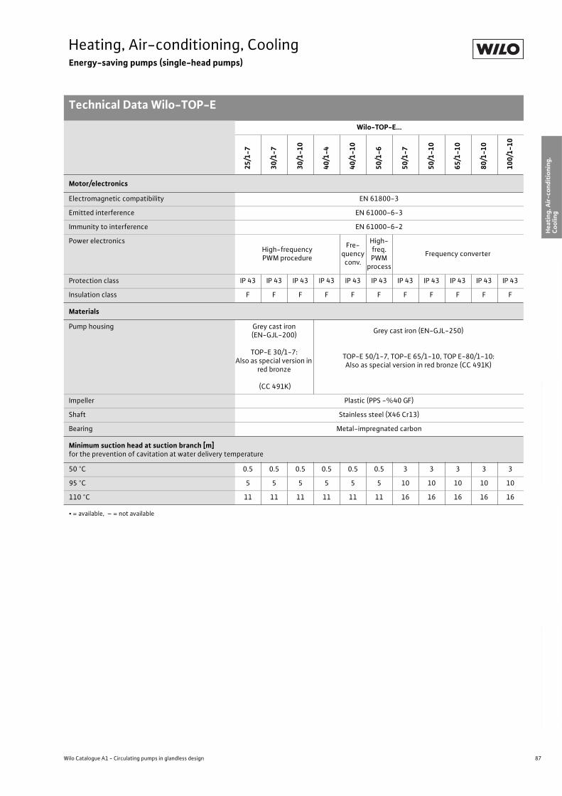
87
Heating, Air-conditioning, CoolingEnergy-saving pumps (single-head pumps)
Technical Data Wilo-TOP-E
Wilo Catalogue A1 - Circulating pumps in glandless design
Hea
tin
g, A
ir-c
on
dit
ion
ing
, C
oo
ling
Po
tab
le w
ater
cir
cula
tio
nSo
lar
ther
mal
Serv
ice/
Acc
esso
ries
, Sys
tem
sSw
itch
gea
rs a
nd
Co
ntr
ol
Dev
ices
P
um
p M
anag
emen
t S y
stem
s
Motor/electronics
Electromagnetic compatibility EN 61800-3
Emitted interference EN 61000-6-3
Immunity to interference EN 61000-6-2
Power electronicsHigh-frequencyPWM procedure
Fre-quencyconv.
High-freq.PWM
process
Frequency converter
Protection class IP 43 IP 43 IP 43 IP 43 IP 43 IP 43 IP 43 IP 43 IP 43 IP 43 IP 43
Insulation class F F F F F F F F F F F
Materials
Pump housing Grey cast iron (EN-GJL-200)
TOP-E 30/1-7:Also as special version in
red bronze
(CC 491K)
Grey cast iron (EN-GJL-250)
TOP-E 50/1-7, TOP-E 65/1-10, TOP E-80/1-10:Also as special version in red bronze (CC 491K)
Impeller Plastic (PPS -%40 GF)
Shaft Stainless steel (X46 Cr13)
Bearing Metal-impregnated carbon
Minimum suction head at suction branch [m]for the prevention of cavitation at water delivery temperature
50 °C 0.5 0.5 0.5 0.5 0.5 0.5 3 3 3 3 3
95 °C 5 5 5 5 5 5 10 10 10 10 10
110 °C 11 11 11 11 11 11 16 16 16 16 16
Wilo-TOP-E...
25
/1-7
30
/1-7
30
/1-1
0
40
/1-4
40
/1-1
0
50
/1-6
50
/1-7
50
/1-1
0
65
/1-1
0
80
/1-1
0
10
0/1
-10
• = available, – = not available
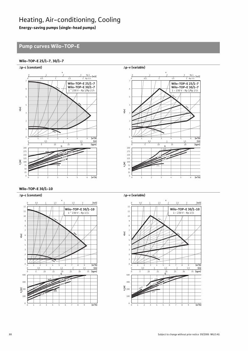
88 Subject to change without prior notice 09/2006 WILO AG
Heating, Air-conditioning, CoolingEnergy-saving pumps (single-head pumps)
Pump curves Wilo-TOP-E
Wilo-TOP-E 25/1-7, 30/1-7
p-c (constant) p-v (variable)
Wilo-TOP-E 30/1-10
p-c (constant) p-v (variable)
Pump curves Wilo-TOP-E
Pump
Curves
200
175
150
125
100
75
50
25
0
0 0,5 1 1,5
0 5 10 15 20
0 0,5 1 1,5 2 Rp 11/4
0 1 2 3 4 5 6
0 1 2 3 4 5 6
Q
[m3/h]
[lgpm]
7
6
5
4
3
2
1
0
[l/s]
[m3/h]
0 1 2 3 Rp 1v
[m/s]
min.
max.
∆ p-c
max.
1 m2 m
3 m4 m5 m
6 m
Wilo-TOP-E 25/1-7Wilo-TOP-E 30/1-71 ~ 230 V - Rp 1/Rp 11/4
min.P 1[W]
H[m
]
200
175
150
125
100
75
50
25
0
0 0,5 1 1,5
0 5 10 15 20
0 0,5 1 1,5 2 Rp 11/4
0 1 2 3 4 5 6
0 1 2 3 4 5 6
Q
[m3/h]
[lgpm]
7
6
5
4
3
2
1
0
[l/s]
[m3/h]
0 1 2 3 Rp 1
v
[m/s]
max.
max.
2 m
3 m4 m5 m
6 m
min.
∆ p-v
Wilo-TOP-E 25/1-7Wilo-TOP-E 30/1-71 ~ 230 V - Rp 1/Rp 11/4
min.P 1[W]
H[m
]
400
300
200
100
0
0 0,5 1 1,5 2 2,5
0 5 10 15 20 25 30 35
0 1 2 3 4 5 6 7 8 9
0 1 2 3 4 5 6 7 8 9
Q
[m3/h]
[lgpm]
12
11
10
9
8
7
6
5
4
3
2
1
0
[l/s]
[m3/h]
min.
max.
p-c
max.
1 m
2 m
4 m6 m
Wilo-TOP-E 30/1-10 1 ~ 230 V - Rp 11/4
0 0,5 1 1,5 2 2,5 3v
[m/s]
8 m
10 m
min.
P 1[W]
H[m
]
400
300
200
100
0
0 0,5 1 1,5 2 2,5
0 5 10 15 20 25 30 35
0 1 2 3 4 5 6 7 8 9
0 1 2 3 4 5 6 7 8 9
Q
[m3/h]
[lgpm]
12
11
10
9
8
7
6
5
4
3
2
1
0
[l/s]
[m3/h]
min.
max.
∆ p-v
max.
8 m 4 m
6 m
Wilo-TOP-E 30/1-10 1 ~ 230 V - Rp 11/4
0 0,5 1 1,5 2 2,5 3
v[m/s]
min.
10 m
P 1[W]
H[m
]
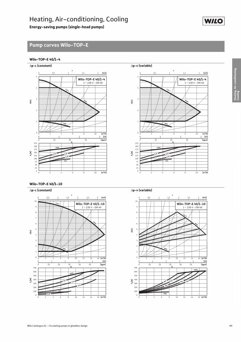
89
Heating, Air-conditioning, CoolingEnergy-saving pumps (single-head pumps)
Pump curves Wilo-TOP-E
Wilo Catalogue A1 - Circulating pumps in glandless design
Hea
tin
g, A
ir-c
on
dit
ion
ing
, C
oo
ling
Po
tab
le w
ater
cir
cula
tio
nSo
lar
ther
mal
Serv
ice/
Acc
esso
ries
, Sys
tem
sSw
itch
gea
rs a
nd
Co
ntr
ol
Dev
ices
P
um
p M
anag
emen
t S y
stem
s
Wilo-TOP-E 40/1-4
p-c (constant) p-v (variable)
Wilo-TOP-E 40/1-10
p-c (constant) p-v (variable)
225
200
175
150
125
100
75
50
25
0
0 1 2 3
0 10 20 30
0 0,5 1 1,5 2
0 2 4 6 8 10
0 2 4 6 8 10
v [m/s]
Q
[m3/h]
[lgpm]
5
4
3
2
1
0
[l/s]
[m3/h]
max.
Wilo-TOP-E 40/1-4 1 ~ 230 V - DN 40
max.
p-c
min.
2 m
1 m 3 m
min.
P 1[W]
H[m
]
225
200
175
150
125
100
75
50
25
0
0 1 2 3
0 10 20 30
0 0,5 1 1,5 2
0 2 4 6 8 10
0 2 4 6 8 10
v [m/s]
Q
[m3/h]
[lgpm]
5
4
3
2
1
0
[l/s]
[m3/h]
max.
Wilo-TOP-E 40/1-4 1 ~ 230 V - DN 40
max.
p-c
min.
2 m
1 m 3 m
min.
P 1[W]
H[m
]
700
600
500
400
300
200
100
0
0 1 2 3 4
0 10 20 30 40 50
0 0,5 1 1,5 2 2,5 3
0 2 4 6 8 10 12 14 16
0 2 4 6 8 10 12 14 16
v [m/s]
Q
[m3/h]
[lgpm]
10
9
8
7
6
5
4
3
2
1
0
[l/s]
[m3/h]
max.
3 m
1 m
5 m 7 m
max.
min.
p-c Wilo-TOP-E 40/1-10 1 ~ 230 V - DN 40
min.
P 1[W]
H[m
]
0 1 2 3 4
0 10 20 30 40 50
0 0,5 1 1,5 2 2,5 3
0 2 4 6 8 10 12 14 16
0 2 4 6 8 10 12 14 16
v [m/s]
Q
[m3/h]
[lgpm]
10
9
8
7
6
5
4
3
2
1
0
[l/s]
[m3/h]
min.
max.
5m 8m
6m
7m
min.
p-v
4m
max.
Wilo-TOP-E 40/1-10 1 ~ 230 V - DN 40
700
600
500
400
300
200
100
0
P 1[W]
H[m
]
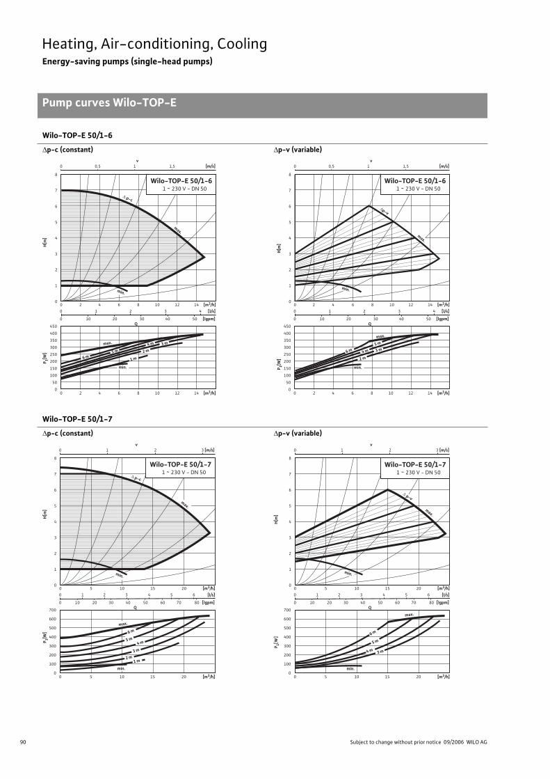
90 Subject to change without prior notice 09/2006 WILO AG
Heating, Air-conditioning, CoolingEnergy-saving pumps (single-head pumps)
Pump curves Wilo-TOP-E
Wilo-TOP-E 50/1-6
p-c (constant) p-v (variable)
Wilo-TOP-E 50/1-7
p-c (constant) p-v (variable)
450
400
350
300
250
200
150
100
50
0
0 1 2 3 4
0 10 20 30 40 50
0 0,5 1 1,5
0 2 4 6 8 10 12 14
v [m/s]
Q
[m3/h]
[lgpm]
8
7
6
5
4
3
2
1
0
[l/s]
[m3/h]
max.
max.
p-c
min.
2 m
1 m
3 m 4 m
5 m
6 m
min.
Wilo-TOP-E 50/1-6 1 ~ 230 V - DN 50
0 2 4 6 8 10 12 14
P 1[W]
H[m
]
450
400
350
300
250
200
150
100
50
0
0 1 2 3 4
0 10 20 30 40 50
0 2 4 6 8 10 12 14
Q
[m3/h]
[lgpm]
8
7
6
5
4
3
2
1
0
[l/s]
[m3/h]
max.
max.
p-v
min.
2 m
3 m 4 m
5 m
min.
0 0,5 1 1,5 v
[m/s]
6 m
0 2 4 6 8 10 12 14
Wilo-TOP-E 50/1-6 1 ~ 230 V - DN 50
P 1[W]
H[m
]
700
600
500
400
300
200
100
0
0 1 2 3 4 5 6
0 10 20 30 40 50 60 70 80
0 5 10 15 20
0 5 10 15 20
Q
[m3/h]
[lgpm]
8
7
6
5
4
3
2
1
0
[l/s]
[m3/h]
min.
max.
p-c
max.
1 m 2 m 3 m
4 m
6 m
0 1 2 3 v
[m/s]
min.
Wilo-TOP-E 50/1-7 1 ~ 230 V - DN 50
5 m
P 1[W]
H[m
]
700
600
500
400
300
200
100
0
0 1 2 3 4 5 6
0 10 20 30 40 50 60 70 80
0 5 10 15 20
0 5 10 15 20
Q
[m3/h]
[lgpm]
8
7
6
5
4
3
2
1
0
[l/s]
[m3/h]
min.
max.
p-v
max.
3 m 4 m
5 m 6 m
0 1 2 3 v
[m/s]
min.
Wilo-TOP-E 50/1-7 1 ~ 230 V - DN 50
P 1[W]
H[m
]
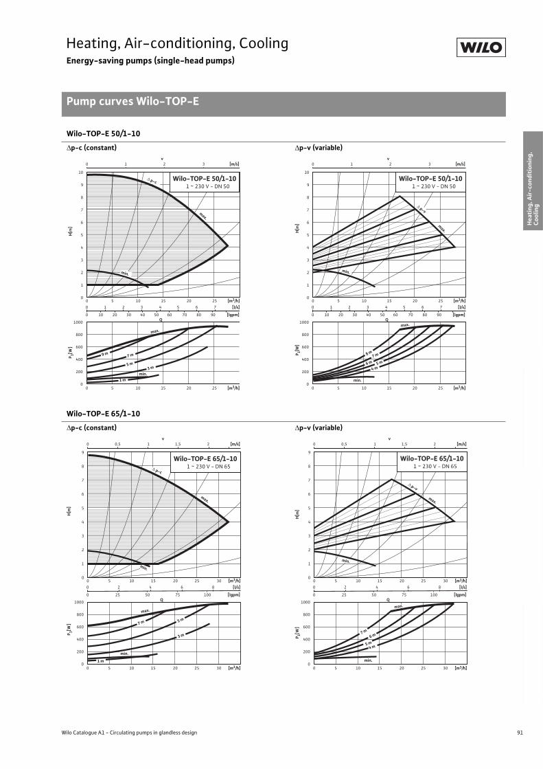
91
Heating, Air-conditioning, CoolingEnergy-saving pumps (single-head pumps)
Pump curves Wilo-TOP-E
Wilo Catalogue A1 - Circulating pumps in glandless design
Hea
tin
g, A
ir-c
on
dit
ion
ing
, C
oo
ling
Po
tab
le w
ater
cir
cula
tio
nSo
lar
ther
mal
Serv
ice/
Acc
esso
ries
, Sys
tem
sSw
itch
gea
rs a
nd
Co
ntr
ol
Dev
ices
P
um
p M
anag
emen
t S y
stem
s
Wilo-TOP-E 50/1-10
p-c (constant) p-v (variable)
Wilo-TOP-E 65/1-10
p-c (constant) p-v (variable)
1000
800
600
400
200
0
0 1 2 3 4 5 6 7
0 10 20 30 40 50 60 70 80 90
0 1 2 3
0 5 10 15 20 25
0 5 10 15 20 25
v [m/s]
Q
[m3/h]
[lgpm]
10
9
8
7
6
5
4
3
2
1
0
[l/s]
[m3/h]
min.
p-c
1 m
3 m
min.
5 m
7 m
max.
9 m
max.
Wilo-TOP-E 50/1-10 1 ~ 230 V - DN 50
P 1[W]
H[m
]
1000
800
600
400
200
0
0 1 2 3 4 5 6 7
0 10 20 30 40 50 60 70 80 90
0 1 2 3
0 5 10 15 20 25
0 5 10 15 20 25
v [m/s]
Q
[m3/h]
[lgpm]
10
9
8
7
6
5
4
3
2
1
0
[l/s]
[m3/h]
min.
p-v
4 m
7 m
min.
5 m 6 m
max.
8 m
max.
Wilo-TOP-E 50/1-10 1 ~ 230 V - DN 50
P 1[W]
H[m
]
1000
800
600
400
200
0
0 2 4 6 8
0 25 50 75 100
0 0,5 1 1,5 2
0 5 10 15 20 25 30
0 5 10 15 20 25 30
v [m/s]
Q
[m3/h]
[lgpm]
9
8
7
6
5
4
3
2
1
0
[l/s]
[m3/h]
max.
max.
p-c
min.
5 m 7 m
3 m
min.
1 m
Wilo-TOP-E 65/1-10 1 ~ 230 V - DN 65
P 1[W]
H[m
]
1000
800
600
400
200
0
0 2 4 6 8
0 25 50 75 100
0 0,5 1 1,5 2
0 5 10 15 20 25 30
0 5 10 15 20 25 30
v [m/s]
Q
[m3/h]
[lgpm]
9
8
7
6
5
4
3
2
1
0
[l/s]
[m3/h]
max.
p-v
min.
5 m
7 m
4 m
min.
6 m
max.
Wilo-TOP-E 65/1-10 1 ~ 230 V - DN 65
P 1[W]
H[m
]
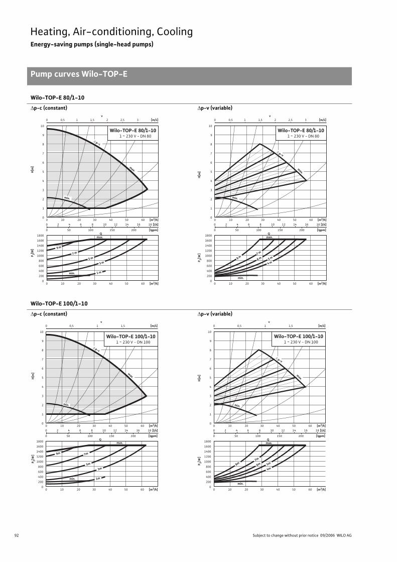
92 Subject to change without prior notice 09/2006 WILO AG
Heating, Air-conditioning, CoolingEnergy-saving pumps (single-head pumps)
Pump curves Wilo-TOP-E
Wilo-TOP-E 80/1-10
p-c (constant) p-v (variable)
Wilo-TOP-E 100/1-10
p-c (constant) p-v (variable)
1800
1600
1400
1200
1000
800
600
400
200
0
0 2 4 6 8 10 12 14 16 18
0 50 100 150 200
0 0,5 1 1,5 2 2,5 3
0 10 20 30 40 50 60
0 10 20 30 40 50 60
v [m/s]
Q
[m3/h]
[lgpm]
10
9
8
7
6
5
4
3
2
1
0
[l/s]
[m3/h]
min.
p-c
1 m
3 m
min.
5 m 7 m
9 m
max.
max.
Wilo-TOP-E 80/1-10 1 ~ 230 V - DN 80
P 1[W]
H[m
]
1800
1600
1400
1200
1000
800
600
400
200
0
0 2 4 6 8 10 12 14 16 18
0 50 100 150 200
0 0,5 1 1,5 2 2,5 3
0 10 20 30 40 50 60
0 10 20 30 40 50 60
v [m/s]
Q
[m3/h]
[lgpm]
10
9
8
7
6
5
4
3
2
1
0
[l/s]
[m3/h]
min.
p-v
4 m
min.
5 m 7 m
max.
max.
6 m
Wilo-TOP-E 80/1-10 1 ~ 230 V - DN 80
8 m
P 1[W]
H[m
]
1800
1600
1400
1200
1000
800
600
400
200
0
0 2 4 6 8 10 12 14 16 18
0 50 100 150 200
0 0,5 1 1,5
0 10 20 30 40 50 60
0 10 20 30 40 50 60
v [m/s]
Q
[m3/h]
[lgpm]
10
9
8
7
6
5
4
3
2
1
0
[l/s]
[m3/h]
min.
p-c
1m
3m 5m
7m 9m
max.
max.
Wilo-TOP-E 100/1-10 1 ~ 230 V - DN 100
min.
P 1[W]
H[m
]
1800
1600
1400
1200
1000
800
600
400
200
0
0 2 4 6 8 10 12 14 16 18
0 50 100 150 200
0 0,5 1 1,5
0 10 20 30 40 50 60
0 10 20 30 40 50 60
v [m/s]
Q
[m3/h]
[lgpm]
10
9
8
7
6
5
4
3
2
1
0
[l/s]
[m3/h]
min.
p-v
4m
min.
5m 7m
8m
max.
max.
6m
Wilo-TOP-E 100/1-10 1 ~ 230 V - DN 100
P 1[W]
H[m
]
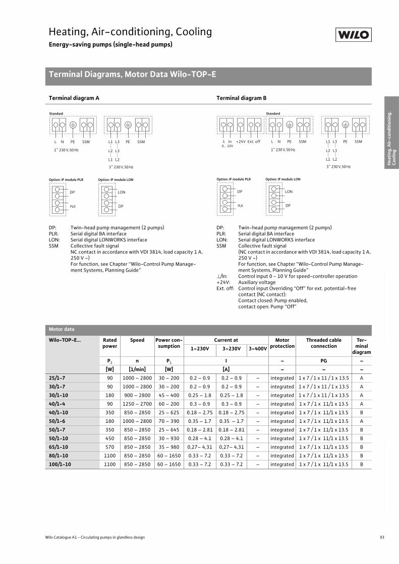
93
Heating, Air-conditioning, CoolingEnergy-saving pumps (single-head pumps)
Terminal Diagrams, Motor Data Wilo-TOP-E
Wilo Catalogue A1 - Circulating pumps in glandless design
Hea
tin
g, A
ir-c
on
dit
ion
ing
, C
oo
ling
Po
tab
le w
ater
cir
cula
tio
nSo
lar
ther
mal
Serv
ice/
Acc
esso
ries
, Sys
tem
sSw
itch
gea
rs a
nd
Co
ntr
ol
Dev
ices
P
um
p M
anag
emen
t S y
stem
s
Terminal diagram A Terminal diagram B
DP: Twin-head pump management (2 pumps)PLR: Serial digital BA interfaceLON: Serial digital LONWORKS interfaceSSM Collective fault signal
NC contact in accordance with VDI 3814, load capacity 1 A, 250 V ~)For function, see Chapter “Wilo-Control Pump Manage-ment Systems, Planning Guide”
DP: Twin-head pump management (2 pumps)PLR: Serial digital BA interfaceLON: Serial digital LONWORKS interfaceSSM Collective fault signal
(NC contact in accordance with VDI 3814, load capacity 1 A, 250 V ~)For function, see Chapter “Wilo-Control Pump Manage-ment Systems, Planning Guide”
/In: Control input 0 - 10 V for speed-controller operation+24V: Auxiliary voltageExt. off: Control input Overriding “Off” for ext. potential-free
contact (NC contact):Contact closed: Pump enabled,contact open: Pump “Off”
Motor data
Wilo-TOP-E... Rated power
Speed Power con-sumption
Current at Motor protection
Threaded cable connection
Ter-minal
diagram1~230V 3~230V 3~400V
P2 n P1 I – PG –
[W] [1/min] [W] [A] – – –
25/1-7 90 1000 – 2800 30 – 200 0.2 – 0.9 0.2 – 0.9 – integrated 1 x 7 / 1 x 11 / 1 x 13.5 A
30/1-7 90 1000 – 2800 30 – 200 0.2 – 0.9 0.2 – 0.9 – integrated 1 x 7 / 1 x 11 / 1 x 13.5 A
30/1-10 180 900 – 2800 45 – 400 0.25 – 1.8 0.25 – 1.8 – integrated 1 x 7 / 1 x 11 / 1 x 13.5 A
40/1-4 90 1250 – 2700 60 – 200 0.3 – 0.9 0.3 – 0.9 – integrated 1 x 7 / 1 x 11/1 x 13.5 A
40/1-10 350 850 – 2850 25 – 625 0.18 – 2.75 0.18 – 2.75 – integrated 1 x 7 / 1 x 11/1 x 13.5 B
50/1-6 180 1000 – 2800 70 – 390 0.35 – 1.7 0.35 – 1.7 – integrated 1 x 7 / 1 x 11/1 x 13.5 A
50/1-7 350 850 – 2850 25 – 645 0.18 – 2.81 0.18 – 2.81 – integrated 1 x 7 / 1 x 11/1 x 13.5 B
50/1-10 450 850 – 2850 30 – 930 0.28 – 4.1 0.28 – 4.1 – integrated 1 x 7 / 1 x 11/1 x 13.5 B
65/1-10 570 850 – 2850 35 – 980 0,27– 4,31 0,27– 4,31 – integrated 1 x 7 / 1 x 11/1 x 13.5 B
80/1-10 1100 850 – 2850 60 – 1650 0.33 – 7.2 0.33 – 7.2 – integrated 1 x 7 / 1 x 11/1 x 13.5 B
100/1-10 1100 850 – 2850 60 – 1650 0.33 – 7.2 0.33 – 7.2 – integrated 1 x 7 / 1 x 11/1 x 13.5 B
Standard
PLR
DP
Option: IF module PLR
DP
LON
Option: IF module LON
L N PE SSM L1 L3
L2 L3
L1 L2
PE SSM
1~ 230 V, 50 Hz
3~ 230 V, 50 Hz
0… 10V
Standard
PLR
DP
Option: IF module PLR
DP
LON
Option: IF module LON
L N PE SSMIn +24V Ext. off L1 L3
L2 L3
L1 L2
PE SSM
1~ 230 V, 50 Hz
3~ 230 V, 50 Hz
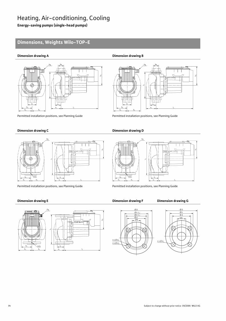
94 Subject to change without prior notice 09/2006 WILO AG
Heating, Air-conditioning, CoolingEnergy-saving pumps (single-head pumps)
Dimensions, Weights Wilo-TOP-E
Dimension drawing A Dimension drawing B
Permitted installation positions, see Planning Guide Permitted installation positions, see Planning Guide
Dimension drawing C Dimension drawing D
Permitted installation positions, see Planning Guide Permitted installation positions, see Planning Guide
Dimension drawing E Dimension drawing F Dimension drawing G
Rp
b 3
a2b1
b2 b2
G a1
l1
l 0
Pg Rp
b 3
a2b1
b2 b2
G a1
l1
l 0
Pg
b 3
b1
b2 b2
a1
l 0
a2 l1
Pg
R 1/8
b 3
b1
b2 b2
a1
l 0
a2 l1
Pg
R 1/8
R 1/8b1
b2 b2
Pg
a1
l1a2
l 0
b 3
Ø D
n x Ø d
Ø k
DN
L2
Ø k Ø d
L 1
1
n x Ø d 2
n x Ø d
Ø D Ø k
DN
Ø d
L
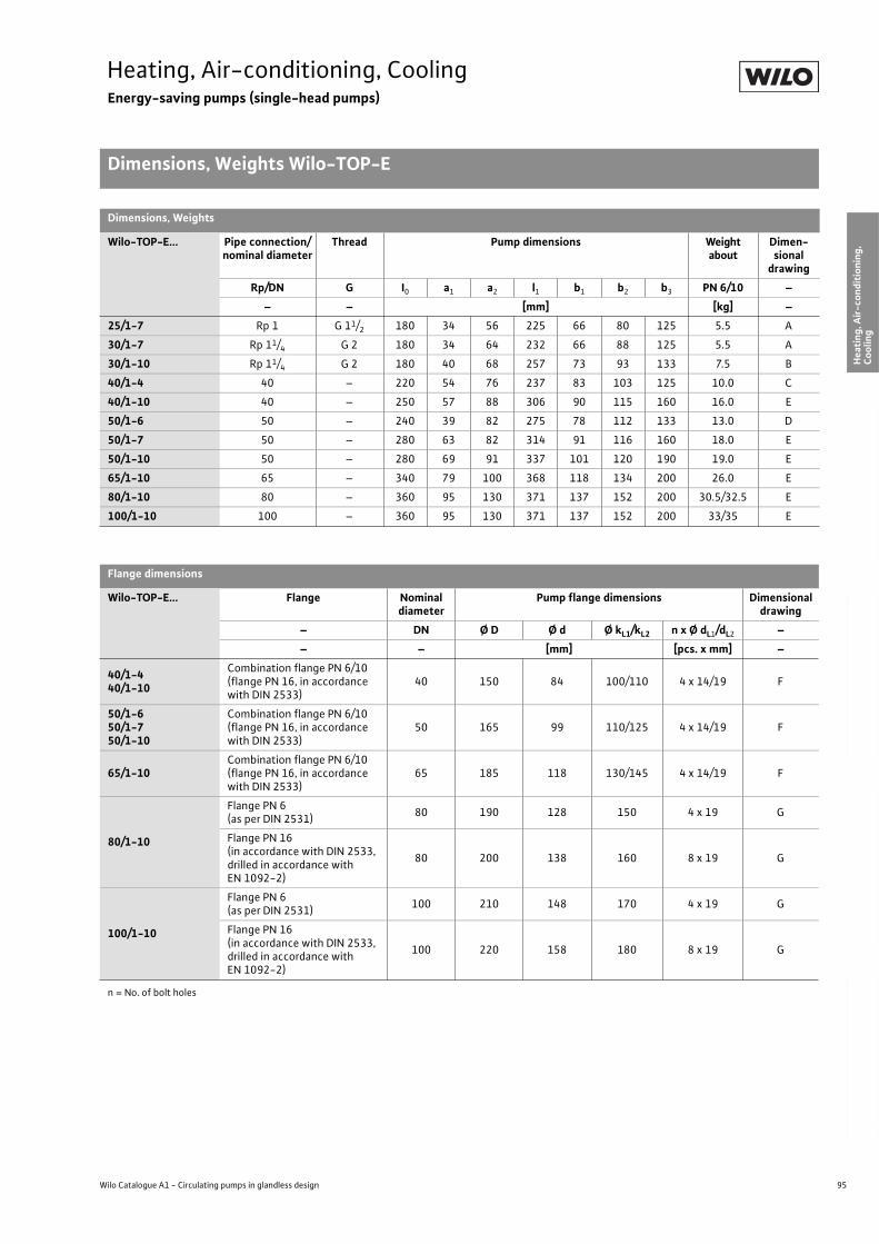
95
Heating, Air-conditioning, CoolingEnergy-saving pumps (single-head pumps)
Dimensions, Weights Wilo-TOP-E
Wilo Catalogue A1 - Circulating pumps in glandless design
Hea
tin
g, A
ir-c
on
dit
ion
ing
, C
oo
ling
Po
tab
le w
ater
cir
cula
tio
nSo
lar
ther
mal
Serv
ice/
Acc
esso
ries
, Sys
tem
sSw
itch
gea
rs a
nd
Co
ntr
ol
Dev
ices
P
um
p M
anag
emen
t S y
stem
s
Dimensions, Weights
Wilo-TOP-E... Pipe connection/nominal diameter
Thread Pump dimensions Weight about
Dimen-sional
drawing
Rp/DN G I0 a1 a2 l1 b1 b2 b3 PN 6/10 –
– – [mm] [kg] –
25/1-7 Rp 1 G 11/2 180 34 56 225 66 80 125 5.5 A
30/1-7 Rp 11/4 G 2 180 34 64 232 66 88 125 5.5 A
30/1-10 Rp 11/4 G 2 180 40 68 257 73 93 133 7.5 B
40/1-4 40 – 220 54 76 237 83 103 125 10.0 C
40/1-10 40 – 250 57 88 306 90 115 160 16.0 E
50/1-6 50 – 240 39 82 275 78 112 133 13.0 D
50/1-7 50 – 280 63 82 314 91 116 160 18.0 E
50/1-10 50 – 280 69 91 337 101 120 190 19.0 E
65/1-10 65 – 340 79 100 368 118 134 200 26.0 E
80/1-10 80 – 360 95 130 371 137 152 200 30.5/32.5 E
100/1-10 100 – 360 95 130 371 137 152 200 33/35 E
Flange dimensions
Wilo-TOP-E... Flange Nominal diameter
Pump flange dimensions Dimensional drawing
– DN Ø D Ø d Ø kL1/kL2 n x Ø dL1/dL2 –
– – [mm] [pcs. x mm] –
40/1-440/1-10
Combination flange PN 6/10(flange PN 16, in accordance with DIN 2533)
40 150 84 100/110 4 x 14/19 F
50/1-650/1-750/1-10
Combination flange PN 6/10(flange PN 16, in accordance with DIN 2533)
50 165 99 110/125 4 x 14/19 F
65/1-10Combination flange PN 6/10(flange PN 16, in accordance with DIN 2533)
65 185 118 130/145 4 x 14/19 F
80/1-10
Flange PN 6(as per DIN 2531)
80 190 128 150 4 x 19 G
Flange PN 16(in accordance with DIN 2533, drilled in accordance with EN 1092-2)
80 200 138 160 8 x 19 G
100/1-10
Flange PN 6(as per DIN 2531)
100 210 148 170 4 x 19 G
Flange PN 16(in accordance with DIN 2533, drilled in accordance with EN 1092-2)
100 220 158 180 8 x 19 G
n = No. of bolt holes
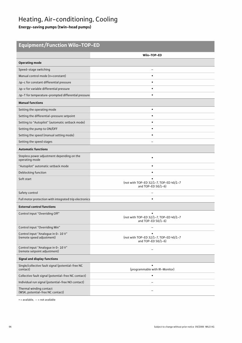
96 Subject to change without prior notice 09/2006 WILO AG
Heating, Air-conditioning, CoolingEnergy-saving pumps (twin-head pumps)
Equipment/Function Wilo-TOP-ED
Wilo-TOP-ED
Operating mode
Speed-stage switching –
Manual control mode (n=constant) •
p-c for constant differential pressure •
p-v for variable differential pressure •
p-T for temperature-prompted differential pressure •
Manual functions
Setting the operating mode •
Setting the differential-pressure setpoint •
Setting to “Autopilot” (automatic setback mode) •
Setting the pump to ON/OFF •
Setting the speed (manual setting mode) •
Setting the speed stages –
Automatic functions
Stepless power adjustment depending on the operating mode
•
“Autopilot” automatic setback mode •
Deblocking function •
Soft start •(not with TOP-ED 32/1-7, TOP-ED 40/1-7
and TOP-ED 50/1-6)
Safety control –
Full motor protection with integrated trip electronics •
External control functions
Control input “Overriding Off” •(not with TOP-ED 32/1-7, TOP-ED 40/1-7
and TOP-ED 50/1-6)
Control input “Overriding Min” –
Control input “Analogue in 0- 10 V” (remote speed adjustment)
•(not with TOP-ED 32/1-7, TOP-ED 40/1-7
and TOP-ED 50/1-6)
Control input “Analogue in 0- 10 V” (remote setpoint adjustment)
–
Signal and display functions
Single/collective fault signal (potential-free NC contact)
•(programmable with IR-Monitor)
Collective fault signal (potential-free NC contact) •
Individual run signal (potential-free NO contact) –
Thermal winding contact (WSK, potential-free NC contact)
–
• = available, – = not available
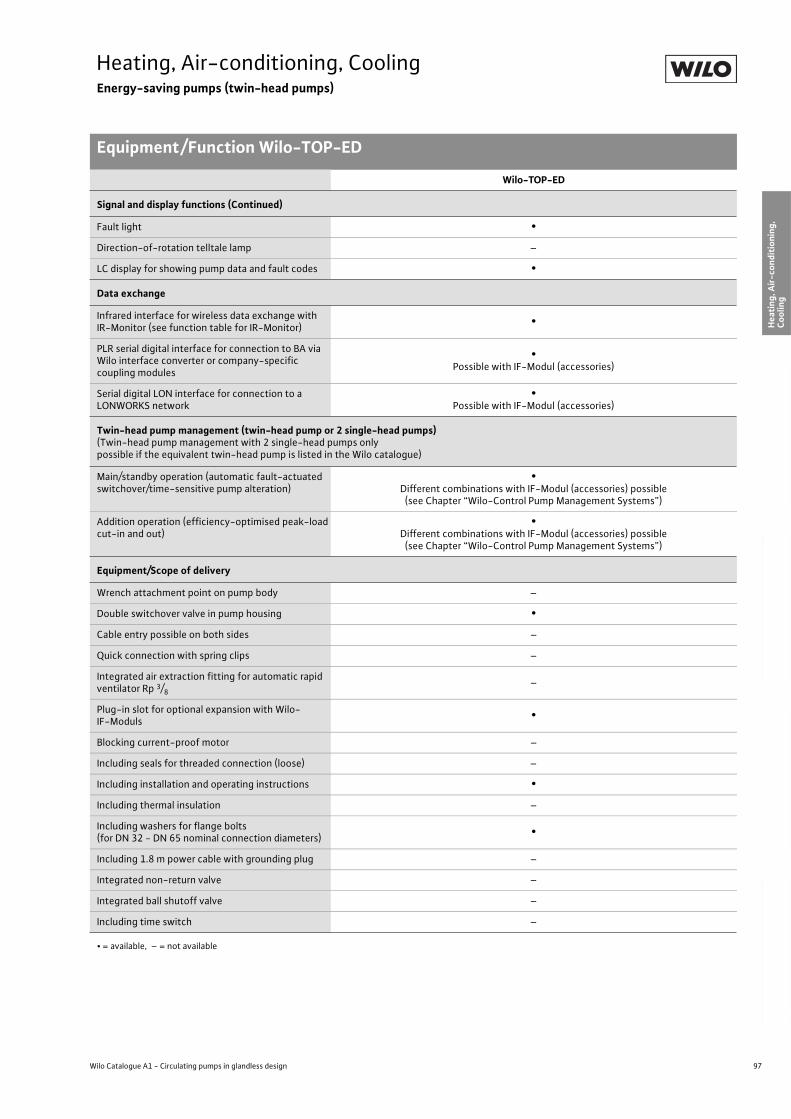
97
Heating, Air-conditioning, CoolingEnergy-saving pumps (twin-head pumps)
Equipment/Function Wilo-TOP-ED
Wilo Catalogue A1 - Circulating pumps in glandless design
Hea
tin
g, A
ir-c
on
dit
ion
ing
, C
oo
ling
Po
tab
le w
ater
cir
cula
tio
nSo
lar
ther
mal
Serv
ice/
Acc
esso
ries
, Sys
tem
sSw
itch
gea
rs a
nd
Co
ntr
ol
Dev
ices
P
um
p M
anag
emen
t S y
stem
s
Signal and display functions (Continued)
Fault light •
Direction-of-rotation telltale lamp –
LC display for showing pump data and fault codes •
Data exchange
Infrared interface for wireless data exchange with IR-Monitor (see function table for IR-Monitor)
•
PLR serial digital interface for connection to BA via Wilo interface converter or company-specific coupling modules
•Possible with IF-Modul (accessories)
Serial digital LON interface for connection to a LONWORKS network
•Possible with IF-Modul (accessories)
Twin-head pump management (twin-head pump or 2 single-head pumps)(Twin-head pump management with 2 single-head pumps only possible if the equivalent twin-head pump is listed in the Wilo catalogue)
Main/standby operation (automatic fault-actuated switchover/time-sensitive pump alteration)
•Different combinations with IF-Modul (accessories) possible
(see Chapter “Wilo-Control Pump Management Systems”)
Addition operation (efficiency-optimised peak-load cut-in and out)
•Different combinations with IF-Modul (accessories) possible
(see Chapter “Wilo-Control Pump Management Systems”)
Equipment/Scope of delivery
Wrench attachment point on pump body –
Double switchover valve in pump housing •
Cable entry possible on both sides –
Quick connection with spring clips –
Integrated air extraction fitting for automatic rapid ventilator Rp 3/8
–
Plug-in slot for optional expansion with Wilo-IF-Moduls
•
Blocking current-proof motor –
Including seals for threaded connection (loose) –
Including installation and operating instructions •
Including thermal insulation –
Including washers for flange bolts(for DN 32 - DN 65 nominal connection diameters)
•
Including 1.8 m power cable with grounding plug –
Integrated non-return valve –
Integrated ball shutoff valve –
Including time switch –
Wilo-TOP-ED
• = available, – = not available

98 Subject to change without prior notice 09/2006 WILO AG
Heating, Air-conditioning, CoolingEnergy-saving pumps (twin-head pumps)
Technical Data Wilo-TOP-ED
Wilo-TOP-ED...
32/1-7 40/1-7 40/1-10 50/1-6 50/1-7 50/1-10 65/1-10 80/1-10
Approved fluids(other fluids on request)
Heating water (In accordance with VDI 2035) • • • • • • • •
Water/glycol mixtures (max. 1:1; mixtures with more than 20% glycol content require rechecking of the pumping data)
• • • • • • • •
Potable water and water for food businesses in accordance with TrinkwV 2001
– – – – – – – –
Performance
Maximum delivery head [m] 7 7 10 7 7 10 9 10
Flow volume max. [m3/h] 10 23 27 24 39 43 59 93
Permitted field of application
Temperature range for utilisation in heating, ventila-tion and A/C systems
at max. ambient temperature +25 °C [°C]at max. ambient temperature +40 °C [°C]
–+20 to +110
Temperature range for utilisation in potable water circulation systems
at max. ambient temperature +40 °C [°C] – – – – – – – –
Maximum permitted total hardness in potable water circulation systems [°d]
– – – – – – – –
Standard version for operating pressure pmax [bar] 6/10 6/10 6/10 6/10 6/10 6/10 6/10 6
Special version for operating pressure pmax [bar]– 16 16 16 16 16 16
10
16
Pipe connections
Screwed connection Rp – – – – – – – –
Nominal connection diameter DN 32 40 40 50 50 50 65 80
Flange for mating flange PN 6, standard version – – – – – – – •
Mating flange for PN 16 flange, special version
– • • • • • • •
Combination flange PN 6/10 for mating flanges PN 6 and PN 16, standard version
• • • • • • • –
Support-bracket mounting (with horizontal shaft only), standard version
– – – – – – • •
Support-bracket mounting (with horizontal shaft only), special version
– • • • • • – –
Electrical connection
Mains connection 1~ [V], standard version 230 230 230 230 230 230 230 230
Mains connection 3~ [V], standard version 230 230 230 230 230 230 230 230
Mains connection 3~ [V], with optional switching plug
– – – – – – – –
Mains frequency [Hz] 50 50 50 50 50 50 50 50
• = available, – = not available

99
Heating, Air-conditioning, CoolingEnergy-saving pumps (twin-head pumps)
Technical Data Wilo-TOP-ED
Wilo Catalogue A1 - Circulating pumps in glandless design
Hea
tin
g, A
ir-c
on
dit
ion
ing
, C
oo
ling
Po
tab
le w
ater
cir
cula
tio
nSo
lar
ther
mal
Serv
ice/
Acc
esso
ries
, Sys
tem
sSw
itch
gea
rs a
nd
Co
ntr
ol
Dev
ices
P
um
p M
anag
emen
t S y
stem
s
Motor/electronics
Electromagnetic compatibility EN 61800-3
Emitted interference EN 61000-6-3
Immunity to interference EN 61000-6-2
Power electronicsHigh-frequency PWM
procedureFrequency converter
High-freq. PWM
processFrequency converter
Protection class IP 43 IP 43 IP 43 IP 43 IP 43 IP 43 IP 43 IP 43
Insulation class F F F F F F F F
Materials
Pump housing Grey cast iron (EN-GJL-250)
Impeller Plastic (PPS - 40% GF)
Shaft Stainless steel (X46 Cr13)
Bearing Metal-impregnated carbon
Minimum suction head at suction branch [m]for the prevention of cavitation at water delivery temperature
50 °C 0,5 0,5 0,5 0,5 3 3 3 3
95 °C 5 5 5 5 10 10 10 10
110 °C 11 11 11 11 16 16 16 16
Wilo-TOP-ED...
32/1-7 40/1-7 40/1-10 50/1-6 50/1-7 50/1-10 65/1-10 80/1-10
• = available, – = not available

100 Subject to change without prior notice 09/2006 WILO AG
Heating, Air-conditioning, CoolingEnergy-saving pumps (twin-head pumps)
Pump curves Wilo-TOP-ED
Wilo-TOP-ED 32/1-7
p-c (constant) p-v (variable)
Wilo-TOP-ED 40/1-7
p-c (constant) p-v (variable)
400
350
300
250
200
150
100
50
0
0 0,5 1 1,5 2 2,5
0 10 20 30
0 1 2 3 4 5 6 7 8 9 10
0 1 2 3 4 5 6 7 8 9 10
Q
[m3/h]
[lgpm]
7
6
5
4
3
2
1
0
[l/s]
[m3/h]
max.
p-c
max.
1 m
2 m 3 m 4 m 6 m
Wilo-TOP-ED 32/1-7 1 ~ 230 V - DN 32
0 0,5 1 1,5 2 2,5 3 v
[m/s]
P1- Wilo-TOP-E 30/1-7
min.
min.
5 m
H[m
]
+
400
350
300
250
200
150
100
50
0
0 0,5 1 1,5 2 2,5
0 10 20 30
0 1 2 3 4 5 6 7 8 9 10
0 1 2 3 4 5 6 7 8 9 10
Q
[m3/h]
[lgpm]
7
6
5
4
3
2
1
0
[l/s]
[m3/h]
min.
max.
p-v
2 m 3 m 4 m
5 m 6 m
max.
Wilo-TOP-ED 32/1-7 1 ~ 230 V - DN 32
0 0,5 1 1,5 2 2,5 3 v
[m/s]
P1- Wilo-TOP-E 30/1-7 min.
P 1[W]
H[m
]
+
900
800
700
600
500
400
300
200
100
0
0 1 2 3 4 5 6 7
0 10 20 30 40 50 60 70 80 90
0 1 2 3 4 5
0 5 10 15 20 25
0 5 10 15 20 25
v [m/s]
Q
[m3/h]
[lgpm]
8
7
6
5
4
3
2
1
0
[l/s]
[m3/h]
max.
p-c
min.
1 m 2 m
3 m 4 m
5 m
6 m
Wilo-TOP-ED 40/1-7 1 ~ 230 V - DN 40
P1- Wilo-TOP-E 50/1-6
max.
min.
+
P 1[W]
H[m
]
900
800
700
600
500
400
300
200
100
0
0 1 2 3 4 5 6 7
0 10 20 30 40 50 60 70 80 90
0 5 10 15 20 25
0 5 10 15 20 25
Q
[m3/h]
[m3/h]
[lgpm]
8
7
6
5
4
3
2
1
0
[l/s]
max.
p-v
2 m
3 m 4 m
5 m
min.
0 1 2 3 4 5 v
[m/s]
Wilo-TOP-ED 40/1-7 1 ~ 230 V - DN 40
min.
max.
P1- Wilo-TOP-E 50/1-6
6 m
P 1[W]
H[m
]
+
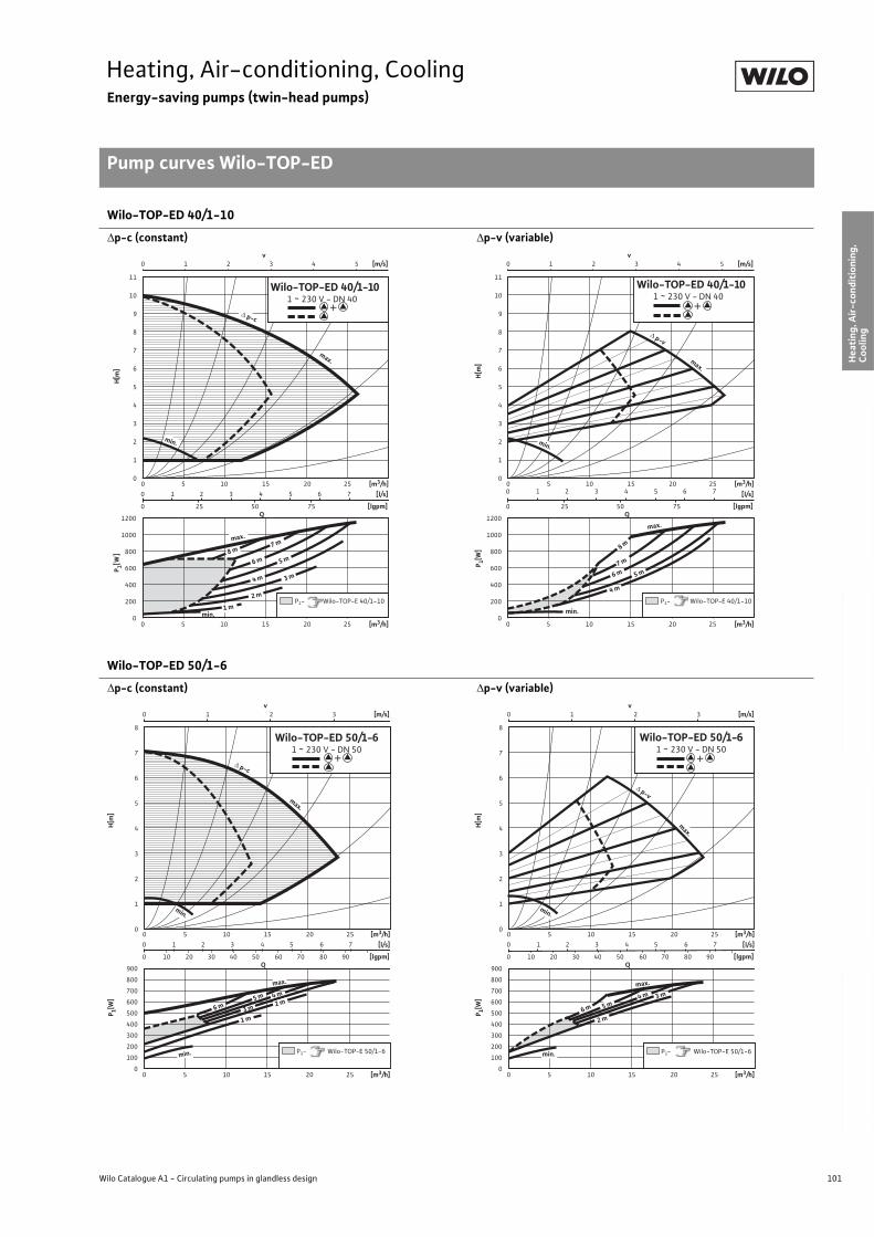
101
Heating, Air-conditioning, CoolingEnergy-saving pumps (twin-head pumps)
Pump curves Wilo-TOP-ED
Wilo Catalogue A1 - Circulating pumps in glandless design
Hea
tin
g, A
ir-c
on
dit
ion
ing
, C
oo
ling
Po
tab
le w
ater
cir
cula
tio
nSo
lar
ther
mal
Serv
ice/
Acc
esso
ries
, Sys
tem
sSw
itch
gea
rs a
nd
Co
ntr
ol
Dev
ices
P
um
p M
anag
emen
t S y
stem
s
Wilo-TOP-ED 40/1-10
p-c (constant) p-v (variable)
Wilo-TOP-ED 50/1-6
p-c (constant) p-v (variable)
1200
1000
800
600
400
200
0
0 1 2 3 4 5 6 7
0 25 50 75
0 1 2 3 4 5
0 5 10 15 20 25
0 5 10 15 20 25
v [m/s]
Q
[m3/h]
[lgpm]
11
10
9
8
7
6
5
4
3
2
1
0
[l/s]
[m3/h] min.
p-c
2 m
3 m
min.
4 m
5 m 6 m
max.
max.
8 m
1 m
Wilo-TOP-ED 40/1-10 1 ~ 230 V - DN 40
P1- Wilo-TOP-E 40/1-10
7 m
+
P 1[W]
H[m
]
1200
1000
800
600
400
200
0
0 1 2 3 4 5 6 7
0 25 50 75
0 1 2 3 4 5
0 5 10 15 20 25
0 5 10 15 20 25
v [m/s]
Q
[m3/h]
[lgpm]
11
10
9
8
7
6
5
4
3
2
1
0
[l/s]
[m3/h]
min.
min.
4 m
5 m 6 m 7 m
max.
8 m
max.
p-v
Wilo-TOP-ED 40/1-10 1 ~ 230 V - DN 40
P1- Wilo-TOP-E 40/1-10
P 1[W]
H[m
]
+
900
800
700
600
500
400
300
200
100
0
0 1 2 3 4 5 6 7
0 10 20 30 40 50 60 70 80 90
0 1 2 3
0 5 10 15 20 25
0 5 10 15 20 25
v [m/s]
Q
[m3/h]
[lgpm]
8
7
6
5
4
3
2
1
0
[l/s]
[m3/h]
p-c
min.
1 m 3 m
4 m 5 m
6 m
Wilo-TOP-ED 50/1-6 1 ~ 230 V - DN 50
max.
P1- Wilo-TOP-E 50/1-6 min.
max.
2 m
+
P 1[W]
H[m
]
900
800
700
600
500
400
300
200
100
0
0 1 2 3 4 5 6 7
0 10 20 30 40 50 60 70 80 90
0 1 2 3
0 5 10 15 20 25
0 5 10 15 20 25
v [m/s]
Q
[m3/h]
[lgpm]
8
7
6
5
4
3
2
1
0
[l/s]
[m3/h]
max.
max.
p-v
2 m
3 m 4 m
min.
Wilo-TOP-ED 50/1-6 1 ~ 230 V - DN 50
min. P1- Wilo-TOP-E 50/1-6
6 m 5 m
P 1[W]
H[m
]
+
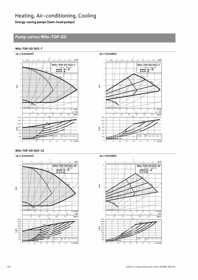
102 Subject to change without prior notice 09/2006 WILO AG
Heating, Air-conditioning, CoolingEnergy-saving pumps (twin-head pumps)
Pump curves Wilo-TOP-ED
Wilo-TOP-ED 50/1-7
p-c (constant) p-v (variable)
Wilo-TOP-ED 50/1-10
p-c (constant) p-v (variable)
1400
1200
1000
800
600
400
200
0
0 2 4 6 8 10
0 20 40 60 80 100 120
0 5 10 15 20 25 30 35
0 5 10 15 20 25 30 35
Q
[m3/h]
[lgpm]
8
7
6
5
4
3
2
1
0
[l/s]
[m3/h]
max.
p-c
min.
1 m
2 m 3 m 4 m
5 m 6 m
min.
max.
Wilo-TOP-ED 50/1-7 1 ~ 230 V - DN 50
P1- Wilo-TOP-E 50/1-7
0 0,5 1 1,5 2 2,5 3 3,5 4 4,5 v
[m/s]
P 1[W]
H[m
]
+
1400
1200
1000
800
600
400
200
0
0 2 4 6 8 10
0 20 40 60 80 100 120
0 0,5 1 1,5 2 2,5 3 3,5 4 4,5
0 5 10 15 20 25 30 35
0 5 10 15 20 25 30 35
v [m/s]
Q
[m3/h]
[lgpm]
8
7
6
5
4
3
2
1
0
[l/s]
[m3/h]
Wilo-TOP-ED 50/1-7 1 ~ 230 V - DN 50
max.
p-v
min.
3 m
6 m
min.
max.
P1- Wilo-TOP-E 50/1-7
5 m 4 m
P 1[W]
H[m
]
+
2000 1800 1600 1400 1200 1000
800 600 400 200
0
0 2 4 6 8 10
0 25 50 75 100 125
0 1 2 3 4 5
0 5 10 15 20 25 30 35 40
0 5 10 15 20 25 30 35 40
v [m/s]
Q
[m3/h]
[lgpm]
10
9
8
7
6
5
4
3
2
1
0
[l/s]
[m3/h] min.
max.
p-c
2 m
max.
min.
6 m 7 m
P1- Wilo-TOP-E 50/1-10
8 m
5 m
4 m
1 m 3 m
Wilo-TOP-ED 50/1-10 1 ~ 230 V - DN 50
P 1[W]
H[m
]
+
2000 1800 1600 1400 1200 1000
800 600 400 200
0
0 2 4 6 8 10
0 25 50 75 100 125
0 1 2 3 4 5
0 5 10 15 20 25 30 35 40
0 5 10 15 20 25 30 35 40
v [m/s]
Q
[m3/h]
[lgpm]
10
9
8
7
6
5
4
3
2
1
0
[l/s]
[m3/h]
min.
max.
p-v
5 m
max.
6 m
min.
7 m
Wilo-TOP-ED 50/1-10 1 ~ 230 V - DN 50
P1- Wilo-TOP-E 50/1-10
4 m
8 m
P 1[W]
H[m
]
+
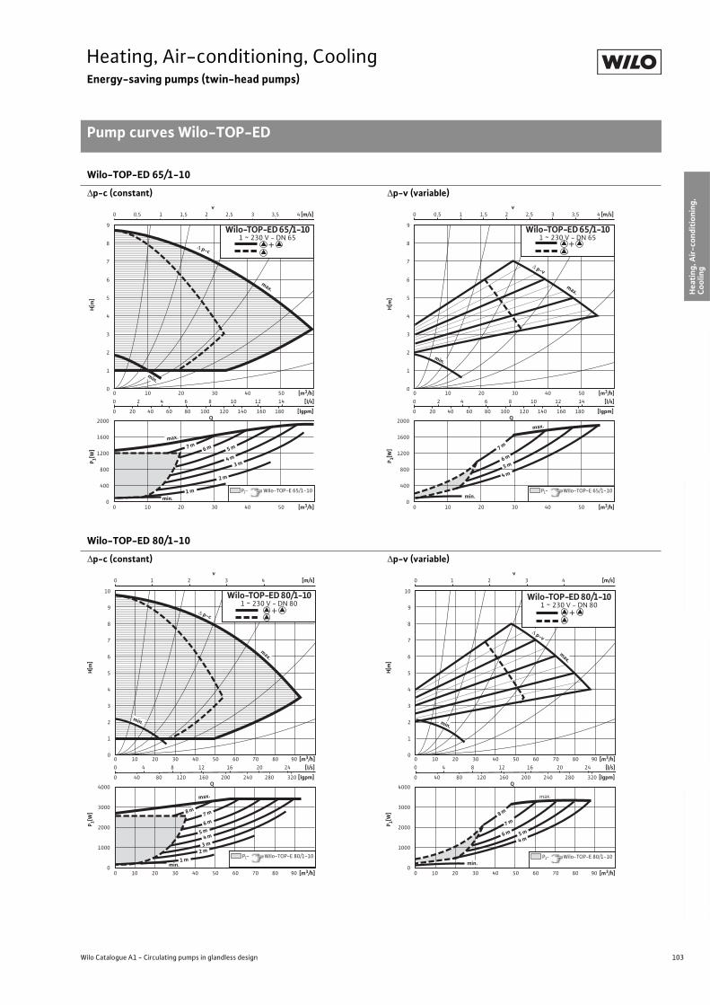
103
Heating, Air-conditioning, CoolingEnergy-saving pumps (twin-head pumps)
Pump curves Wilo-TOP-ED
Wilo Catalogue A1 - Circulating pumps in glandless design
Hea
tin
g, A
ir-c
on
dit
ion
ing
, C
oo
ling
Po
tab
le w
ater
cir
cula
tio
nSo
lar
ther
mal
Serv
ice/
Acc
esso
ries
, Sys
tem
sSw
itch
gea
rs a
nd
Co
ntr
ol
Dev
ices
P
um
p M
anag
emen
t S y
stem
s
Wilo-TOP-ED 65/1-10
p-c (constant) p-v (variable)
Wilo-TOP-ED 80/1-10
p-c (constant) p-v (variable)
2000
1600
1200
800
400
0
0 2 4 6 8 10 12 14
0 20 40 60 80 100 120 140 160 180
0 0,5 1 1,5 2 2,5 3 3,5 4
0 10 20 30 40 50
0 10 20 30 40 50
v [m/s]
Q
[m3/h]
[lgpm]
9
8
7
6
5
4
3
2
1
0
[l/s]
[m3/h]
min.
max.
p-c
min.
5 m 6 m 7 m
2 m
1 m
3 m 4 m
Wilo-TOP-ED 65/1-10 1 ~ 230 V - DN 65
P1- Wilo-TOP-E 65/1-10
max.
P 1[W]
H[m
]
+
2000
1600
1200
800
400
0
0 10 20 30 40 50
0 10 20 30 40 50
Q
[m3/h]
9
8
7
6
5
4
3
2
1
0
[m3/h]
max.
p-v
min.
6 m
4 m 5 m
min.
max.
0 2 4 6 8 10 12 14
0 20 40 60 80 100 120 140 160 180 [lgpm]
[l/s]
7 m
0 0,5 1 1,5 2 2,5 3 3,5 4 v
[m/s]
P1- Wilo-TOP-E 65/1-10
Wilo-TOP-ED 65/1-10 1 ~ 230 V - DN 65
P 1[W]
H[m
]
+
4000
3000
2000
1000
0
0 4 8 12 16 20 24
0 40 80 120 160 200 240 280 320
0 1 2 3 4
0 10 20 30 40 50 60 70 80 90
0 10 20 30 40 50 60 70 80 90
v [m/s]
Q
[m3/h]
[lgpm]
10
9
8
7
6
5
4
3
2
1
0
[l/s]
[m3/h]
p-c
1 m 2 m
3 m
min.
4 m 5 m 6 m 7 m
max.
max.
Wilo-TOP-ED 80/1-10 1 ~ 230 V - DN 80
P1- Wilo-TOP-E 80/1-10
min.
8 m
P 1[W]
H[m
]
+
4000
3000
2000
1000
0
0 4 8 12 16 20 24
0 40 80 120 160 200 240 280 320
0 1 2 3 4
0 10 20 30 40 50 60 70 80 90
0 10 20 30 40 50 60 70 80 90
v [m/s]
Q
[m3/h]
[lgpm]
10
9
8
7
6
5
4
3
2
1
0
[l/s]
[m3/h]
p-v
min.
4 m 5 m
6 m 7 m
8 m
max.
max.
Wilo-TOP-ED 80/1-10 1 ~ 230 V - DN 80
min. P1- Wilo-TOP-E 80/1-10
P 1[W]
H[m
]
+
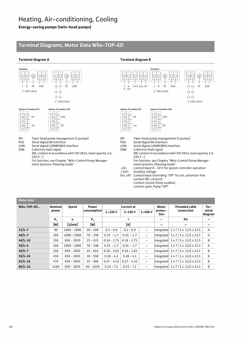
104 Subject to change without prior notice 09/2006 WILO AG
Heating, Air-conditioning, CoolingEnergy-saving pumps (twin-head pumps)
Terminal Diagrams, Motor Data Wilo-TOP-ED
Terminal diagram A Terminal diagram B
DP: Twin-head pump management (2 pumps)PLR: Serial digital BA interfaceLON: Serial digital LONWORKS interfaceSSM Collective fault signal
(NC contact in accordance with VDI 3814, load capacity 1 A, 250 V ~)For function, see Chapter “Wilo-Control Pump Manage-ment Systems, Planning Guide”
DP: Twin-head pump management (2 pumps)PLR: Serial digital BA interfaceLON: Serial digital LONWORKS interfaceSSM Collective fault signal
(NC contact in accordance with VDI 3814, load capacity 1 A, 250 V ~)For function, see Chapter “Wilo-Control Pump Manage-ment Systems, Planning Guide”
/In: Control input 0 - 10 V for speed-controller operation+24V: Auxiliary voltageExt. off: Control input Overriding “Off” for ext. potential-free
contact (NC contact):Contact closed: Pump enabled,contact open: Pump “Off”
Motor data
Wilo-TOP-ED... Nominal power
Speed Power consumption
Current at Motor protec-
tion
Threaded cable connection
Ter-minal
diagram1~230 V 3~230 V 3~400 V
P2 n P1 I – PG –
[W] [1/min] [W] [A] – – –
32/1-7 90 1000 - 2800 30 - 200 0.2 - 0.9 0.2 - 0.9 – integrated 1 x 7 / 1 x 11/1 x 13.5 A
40/1-7 180 1000 - 2800 70 - 390 0.35 - 1.7 0.35 - 1.7 – integrated 1 x 7 / 1 x 11/1 x 13.5 A
40/1-10 350 850 - 2850 25 - 625 0.18 - 2.75 0.18 - 2.75 – integrated 1 x 7 / 1 x 11/1 x 13.5 B
50/1-6 180 1000 - 2800 70 - 390 0.35 - 1.7 0.35 - 1.7 – integrated 1 x 7 / 1 x 11/1 x 13.5 A
50/1-7 350 850 - 2850 25 - 645 0.18 - 2.81 0.18 - 2.81 – integrated 1 x 7 / 1 x 11/1 x 13.5 B
50/1-10 450 850 - 2850 30 - 930 0.28 - 4.1 0.28 - 4.1 – integrated 1 x 7 / 1 x 11/1 x 13.5 B
65/1-10 570 850 - 2850 35 - 980 0.27 - 4.31 0.27 - 4.31 – integrated 1 x 7 / 1 x 11/1 x 13.5 B
80/1-10 1100 850 - 2850 60 - 1650 0.33 - 7.2 0.33 - 7.2 – integrated 1 x 7 / 1 x 11/1 x 13.5 B
Standard
PLR
DP
Option: IF module PLR
DP
LON
Option: IF module LON
L N PE SSM L1 L3
L2 L3
L1 L2
PE SSM
1~ 230 V, 50 Hz
3~ 230 V, 50 Hz
0… 10V
Standard
PLR
DP
Option: IF module PLR
DP
LON
Option: IF module LON
L N PE SSMIn +24V Ext. off L1 L3
L2 L3
L1 L2
PE SSM
1~ 230 V, 50 Hz
3~ 230 V, 50 Hz
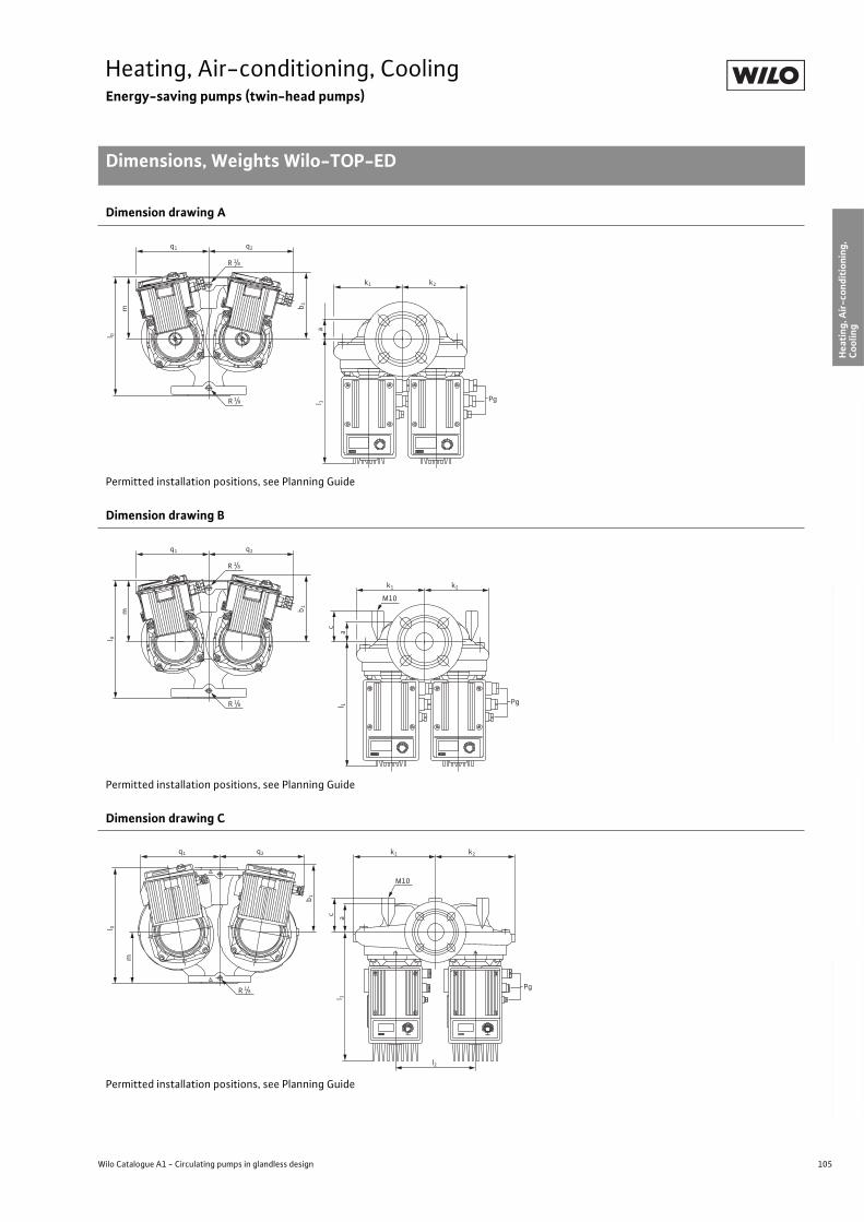
105
Heating, Air-conditioning, CoolingEnergy-saving pumps (twin-head pumps)
Dimensions, Weights Wilo-TOP-ED
Wilo Catalogue A1 - Circulating pumps in glandless design
Hea
tin
g, A
ir-c
on
dit
ion
ing
, C
oo
ling
Po
tab
le w
ater
cir
cula
tio
nSo
lar
ther
mal
Serv
ice/
Acc
esso
ries
, Sys
tem
sSw
itch
gea
rs a
nd
Co
ntr
ol
Dev
ices
P
um
p M
anag
emen
t S y
stem
s
Dimension drawing A
Permitted installation positions, see Planning Guide
Dimension drawing B
Permitted installation positions, see Planning Guide
Dimension drawing C
Permitted installation positions, see Planning Guide
m
l 0
l 1a
k2k1
q1 q2
R 1/8
R 1/8
b 1
Pg
m
l 0
l 1a
k2k1
q1 q2
R 1/8
R 1/8
b 1
Pg
c
M10
m
l 1
l 0
ac
k2
l2
k1q1 q2
b 1
R 1/8Pg
M10
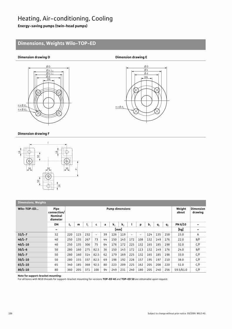
106 Subject to change without prior notice 09/2006 WILO AG
Heating, Air-conditioning, CoolingEnergy-saving pumps (twin-head pumps)
Dimensions, Weights Wilo-TOP-ED
Dimension drawing D Dimension drawing E
Dimension drawing F
Dimensions, Weights
Wilo-TOP-ED... Pipe connection/
Nominal diameter
Pump dimensions Weight about
Dimension drawing
DN I0 m l1 c a k1 k2 l p b1 q1 q2 PN 6/10 –
– [mm] [kg] –
32/1-7 32 220 115 232 - 39 126 119 - - 124 135 158 15.0 A
40/1-7 40 250 135 267 73 44 150 143 172 108 132 149 176 22.0 B/F
40/1-10 40 250 135 306 75 64 178 172 225 132 165 185 198 32.0 C/F
50/1-6 50 280 160 275 82,5 36 150 143 172 113 132 149 176 24.0 B/F
50/1-7 50 280 160 314 82,5 62 179 169 225 132 165 185 198 33.0 C/F
50/1-10 50 280 155 337 82,5 69 198 192 228 157 195 197 210 38.0 C/F
65/1-10 65 340 185 368 92,5 80 223 209 225 162 205 208 220 51.0 C/F
80/1-10 80 360 205 371 100 94 249 231 240 180 205 240 256 59.5/61.0 C/F
Note for support-bracket mounting:For all bores with M10 threads for support-bracket mounting for versions TOP-ED 40 and TOP-ED 50 are obtainable upon request.
Ø D
n x Ø d
Ø k
DN
L2
Ø k Ø d
L 1
1
n x Ø d 2
n x Ø d
Ø D Ø k
DN
Ø d
L
l
50
p
50
18
18 18
303030
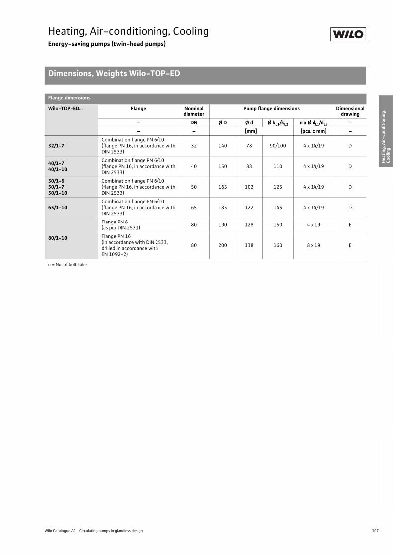
107
Heating, Air-conditioning, CoolingEnergy-saving pumps (twin-head pumps)
Dimensions, Weights Wilo-TOP-ED
Wilo Catalogue A1 - Circulating pumps in glandless design
Hea
tin
g, A
ir-c
on
dit
ion
ing
, C
oo
ling
Po
tab
le w
ater
cir
cula
tio
nSo
lar
ther
mal
Serv
ice/
Acc
esso
ries
, Sys
tem
sSw
itch
gea
rs a
nd
Co
ntr
ol
Dev
ices
P
um
p M
anag
emen
t S y
stem
s
Flange dimensions
Wilo-TOP-ED... Flange Nominal diameter
Pump flange dimensions Dimensional drawing
– DN Ø D Ø d Ø kL1/kL2 n x Ø dL1/dL2 –
– – [mm] [pcs. x mm] –
32/1-7Combination flange PN 6/10(flange PN 16, in accordance with DIN 2533)
32 140 78 90/100 4 x 14/19 D
40/1-740/1-10
Combination flange PN 6/10(flange PN 16, in accordance with DIN 2533)
40 150 88 110 4 x 14/19 D
50/1-650/1-750/1-10
Combination flange PN 6/10(flange PN 16, in accordance with DIN 2533)
50 165 102 125 4 x 14/19 D
65/1-10Combination flange PN 6/10(flange PN 16, in accordance with DIN 2533)
65 185 122 145 4 x 14/19 D
80/1-10
Flange PN 6 (as per DIN 2531)
80 190 128 150 4 x 19 E
Flange PN 16(in accordance with DIN 2533,drilled in accordance with EN 1092-2)
80 200 138 160 8 x 19 E
n = No. of bolt holes
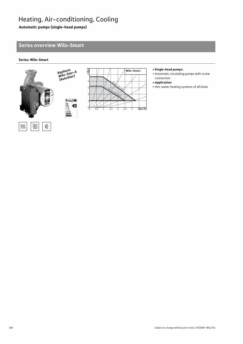
108 Subject to change without prior notice 09/2006 WILO AG
Heating, Air-conditioning, CoolingAutomatic pumps (single-head pumps)
Series overview Wilo-Smart
Series: Wilo-Smart
> Single-head pumps:• Automatic circulating pumps with screw
connection
> Application:• Hot-water heating systems of all kinds
Replaces
Wilo-Star-
A
(AutoStar)
Wilo-Smart
Smart 25/30/4
Smart 25/30/6
00
1
2
3
4
5
10,5 21,5 3 Q[m³/h]2,5
H[m
]
109
Heating, Air-conditioning, CoolingAutomatic pumps (single-head pumps)
Series overview Wilo-Smart
Wilo Catalogue A1 - Circulating pumps in glandless design
Hea
tin
g, A
ir-c
on
dit
ion
ing
, C
oo
ling
Po
tab
le w
ater
cir
cula
tio
nSo
lar
ther
mal
Serv
ice/
Acc
esso
ries
, Sys
tem
sSw
itch
gea
rs a
nd
Co
ntr
ol
Dev
ices
P
um
p M
anag
emen
t S y
stem
s
Series: Wilo-Smart
> Product advantages:• Simple pipe connection thanks to the safe and practical wrench attachment point on the pump
body.
• Secure electrical connection through ergonomically optimised terminal box.
Quick connection with spring clips
• Easy operation. Ex-works setting suitable for 80% of all heating systems requirements. Simple
selection of the 3 pre-programmed control channels is accomplished with the “red button”.
• The Wilo-Smart automatic control mode prevents flow noise in the heating system and
reduces power consumption.
• Operational reliability thanks to automatic deblocking function. A special bronze filter pre-
vents particles from entering the motor space.
>Additional information: Page:• Planning Guide: . . . . . . . . . . . . . . . . . . 6
• Equipment/Function: . . . . . . . . . . . . . 110
• Technical Data: . . . . . . . . . . . . . . . . . . 112
• Pump Curves: . . . . . . . . . . . . . . . . . . . . 114
• Terminal Diagrams, Motor Data:. . . . 115
• Dimensions, Weights: . . . . . . . . . . . . . 115
• Service/Accessories: . . . . . . . . . . . . . . 325
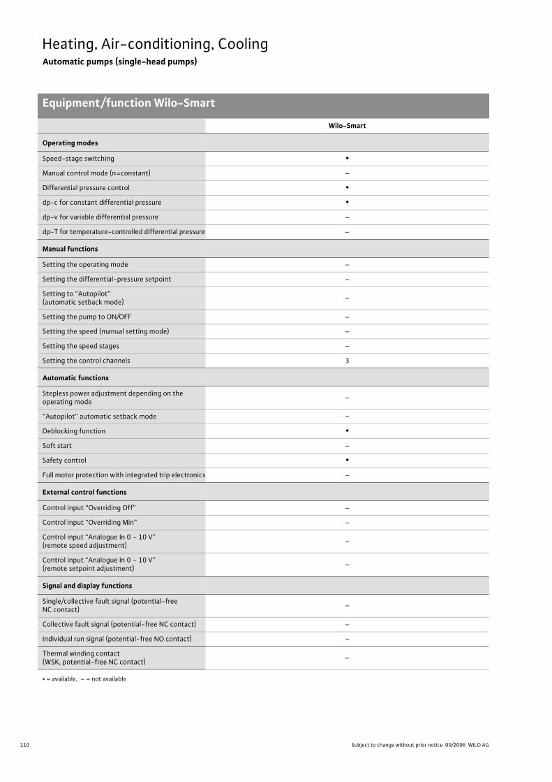
110 Subject to change without prior notice 09/2006 WILO AG
Heating, Air-conditioning, CoolingAutomatic pumps (single-head pumps)
Equipment/function Wilo-Smart
Wilo-Smart
Operating modes
Speed-stage switching •
Manual control mode (n=constant) –
Differential pressure control •
dp-c for constant differential pressure •
dp-v for variable differential pressure –
dp-T for temperature-controlled differential pressure –
Manual functions
Setting the operating mode –
Setting the differential-pressure setpoint –
Setting to “Autopilot”(automatic setback mode)
–
Setting the pump to ON/OFF –
Setting the speed (manual setting mode) –
Setting the speed stages –
Setting the control channels 3
Automatic functions
Stepless power adjustment depending on the operating mode
–
“Autopilot” automatic setback mode –
Deblocking function •
Soft start –
Safety control •
Full motor protection with integrated trip electronics –
External control functions
Control input “Overriding Off” –
Control input “Overriding Min” –
Control input “Analogue In 0 - 10 V” (remote speed adjustment)
–
Control input “Analogue In 0 - 10 V” (remote setpoint adjustment)
–
Signal and display functions
Single/collective fault signal (potential-free NC contact)
–
Collective fault signal (potential-free NC contact) –
Individual run signal (potential-free NO contact) –
Thermal winding contact (WSK, potential-free NC contact)
–
• = available, – = not available
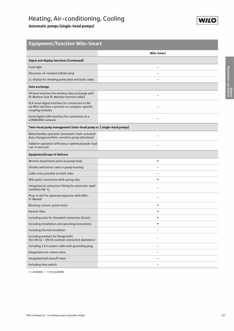
111
Heating, Air-conditioning, CoolingAutomatic pumps (single-head pumps)
Equipment/function Wilo-Smart
Wilo Catalogue A1 - Circulating pumps in glandless design
Hea
tin
g, A
ir-c
on
dit
ion
ing
, C
oo
ling
Po
tab
le w
ater
cir
cula
tio
nSo
lar
ther
mal
Serv
ice/
Acc
esso
ries
, Sys
tem
sSw
itch
gea
rs a
nd
Co
ntr
ol
Dev
ices
P
um
p M
anag
emen
t S y
stem
s
Signal and display functions (Continued)
Fault light –
Direction-of-rotation telltale lamp –
LC display for showing pump data and fault codes –
Data exchange
Infrared interface for wireless data exchange with IR-Monitor (see IR-Monitor function table)
–
PLR serial digital interface for connection to BA via Wilo interface converter or company-specific coupling modules
–
Serial digital LON interface for connection to a LONWORKS network
–
Twin-head pump management (twin-head pump or 2 single-head pumps)
Main/standby operation (automatic fault-actuated duty changeover/time-sensitive pump alteration)
–
Addition operation (efficiency-optimised peak-load cut-in and out)
–
Equipment/Scope of delivery
Wrench attachment point on pump body •
Double switchover valve in pump housing –
Cable entry possible on both sides –
Wilo quick connection with spring clips •
Integrated air extraction fitting for automatic rapid ventilator Rp 3/8
–
Plug-in slot for optional expansion with Wilo-IF-Moduls
–
Blocking current-proof motor •
Particle filter •
Including seals for threaded connection (loose) •
Including installation and operating instructions •
Including thermal insulation –
Including washers for flange bolts(for DN 32 - DN 65 nominal connection diameters)
–
Including 1.8 m power cable with grounding plug –
Integrated non-return valve –
Integrated ball shutoff valve –
Including time switch –
Wilo-Smart
• = available, – = not available
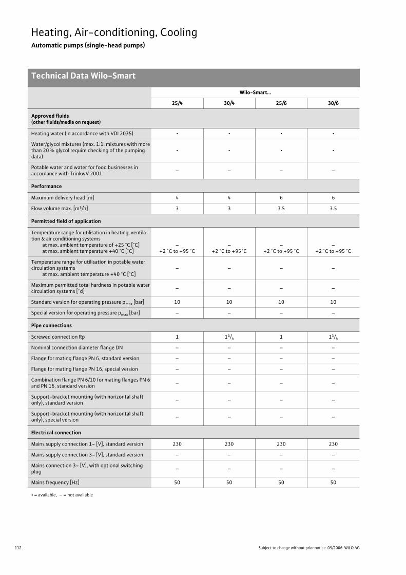
112 Subject to change without prior notice 09/2006 WILO AG
Heating, Air-conditioning, CoolingAutomatic pumps (single-head pumps)
Technical Data Wilo-Smart
Wilo-Smart...
25/4 30/4 25/6 30/6
Approved fluids(other fluids/media on request)
Heating water (In accordance with VDI 2035) • • • •
Water/glycol mixtures (max. 1:1; mixtures with more than 20% glycol require checking of the pumping data)
• • • •
Potable water and water for food businesses in accordance with TrinkwV 2001
– – – –
Performance
Maximum delivery head [m] 4 4 6 6
Flow volume max. [m3/h] 3 3 3.5 3.5
Permitted field of application
Temperature range for utilisation in heating, ventila-tion & air conditioning systems
at max. ambient temperature of +25 °C [°C]at max. ambient temperature +40 °C [°C]
–+2 °C to +95 °C
–+2 °C to +95°C
–+2 °C to +95 °C
–+2 °C to +95 °C
Temperature range for utilisation in potable water circulation systems
at max. ambient temperature +40 °C [°C]– – – –
Maximum permitted total hardness in potable water circulation systems [°d]
– – – –
Standard version for operating pressure pmax [bar] 10 10 10 10
Special version for operating pressure pmax [bar] – – – –
Pipe connections
Screwed connection Rp 1 11/4 1 11/4
Nominal connection diameter flange DN – – – –
Flange for mating flange PN 6, standard version – – – –
Flange for mating flange PN 16, special version – – – –
Combination flange PN 6/10 for mating flanges PN 6 and PN 16, standard version
– – – –
Support-bracket mounting (with horizontal shaft only), standard version
– – – –
Support-bracket mounting (with horizontal shaft only), special version
– – – –
Electrical connection
Mains supply connection 1~ [V], standard version 230 230 230 230
Mains supply connection 3~ [V], standard version – – – –
Mains connection 3~ [V], with optional switching plug
– – – –
Mains frequency [Hz] 50 50 50 50
• = available, – = not available
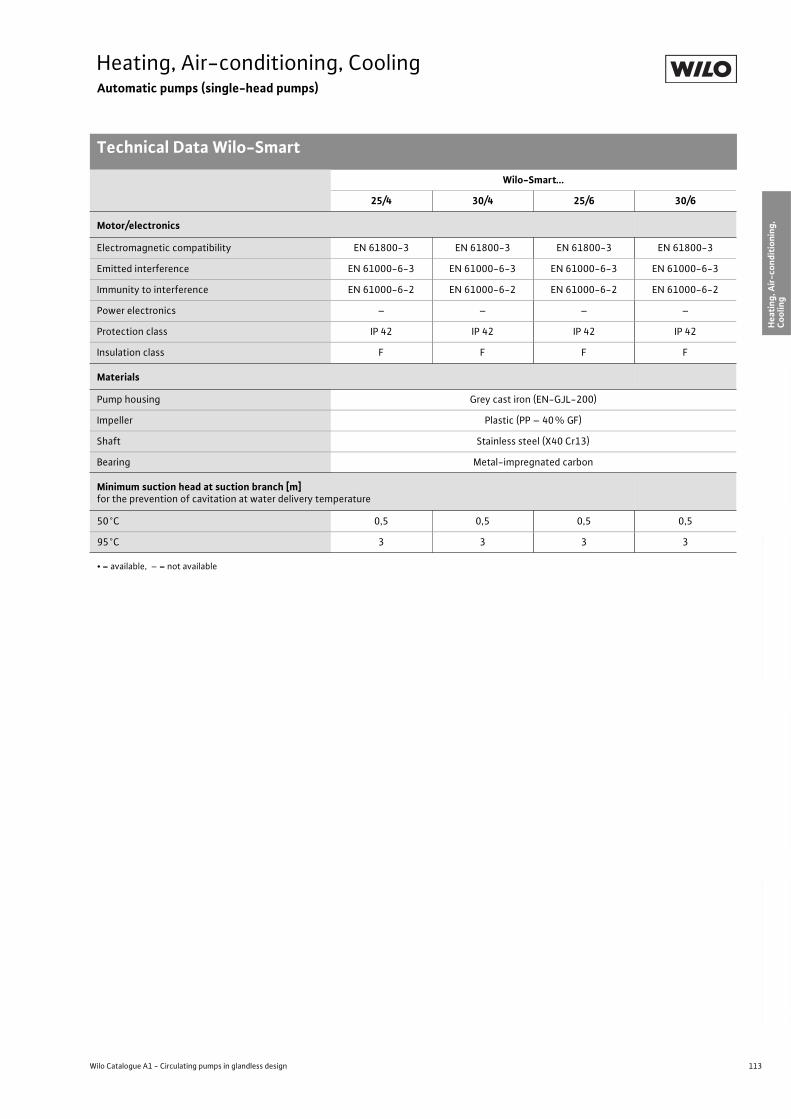
113
Heating, Air-conditioning, CoolingAutomatic pumps (single-head pumps)
Technical Data Wilo-Smart
Wilo Catalogue A1 - Circulating pumps in glandless design
Hea
tin
g, A
ir-c
on
dit
ion
ing
, C
oo
ling
Po
tab
le w
ater
cir
cula
tio
nSo
lar
ther
mal
Serv
ice/
Acc
esso
ries
, Sys
tem
sSw
itch
gea
rs a
nd
Co
ntr
ol
Dev
ices
P
um
p M
anag
emen
t S y
stem
s
Motor/electronics
Electromagnetic compatibility EN 61800-3 EN 61800-3 EN 61800-3 EN 61800-3
Emitted interference EN 61000-6-3 EN 61000-6-3 EN 61000-6-3 EN 61000-6-3
Immunity to interference EN 61000-6-2 EN 61000-6-2 EN 61000-6-2 EN 61000-6-2
Power electronics – – – –
Protection class IP 42 IP 42 IP 42 IP 42
Insulation class F F F F
Materials
Pump housing Grey cast iron (EN-GJL-200)
Impeller Plastic (PP – 40% GF)
Shaft Stainless steel (X40 Cr13)
Bearing Metal-impregnated carbon
Minimum suction head at suction branch [m]for the prevention of cavitation at water delivery temperature
50°C 0,5 0,5 0,5 0,5
95°C 3 3 3 3
Wilo-Smart...
25/4 30/4 25/6 30/6
• = available, – = not available
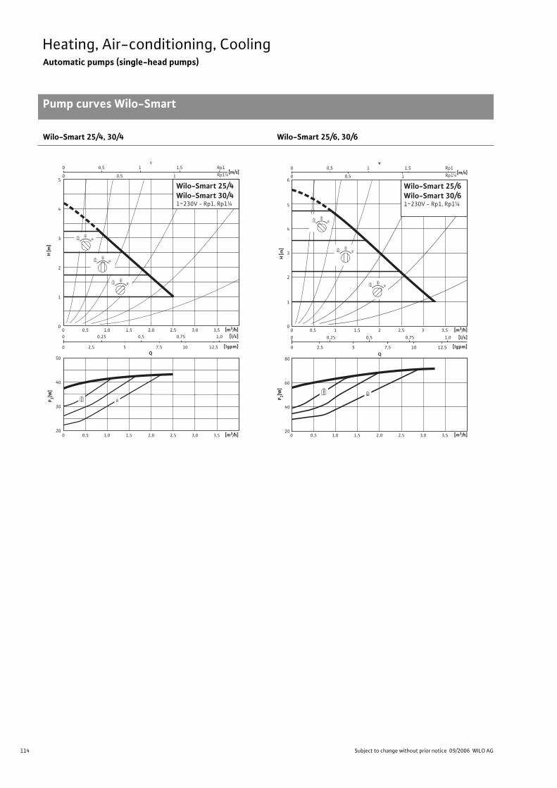
114 Subject to change without prior notice 09/2006 WILO AG
Heating, Air-conditioning, CoolingAutomatic pumps (single-head pumps)
Pump curves Wilo-Smart
Wilo-Smart 25/4, 30/4 Wilo-Smart 25/6, 30/6
H [m
]
0 0,5 1,0 1,5 2,0 2,5 3,0 3,5
0 0,5 1,0 1,5 2,0 2,5 3,0 3,5
0 0,25 0,5 0,75 1,0
0 2,5 5 7,5 10 12,5
5
4
3
2
1
0
50
40
30
20
Q
[l/s]
[lgpm]
[m3/h]
[m3/h]
P 1[W]
Wilo-Smart 25/4Wilo-Smart 30/41~230V - Rp1, Rp1¼
[m/s]0
0
0,5
0,5
1 1,5
1
vRp1
Rp1¼
H [m
]
[m/s]
Q
[l/s]
0 2,5 5 7,5 10 12,5 [lgpm]
[m3/h]
0 0,5 1,0 1,5 2,0 2,5 3,0 3,5 [m3/h]20
40
60
80
P 1[W]
Wilo-Smart 25/6Wilo-Smart 30/61~230V - Rp1, Rp1¼
0
0
0
1
2
3
4
5
6
0,5
0,5
1 1,5
1
0 0,5 1 21,5
0 0,25 0,5 0,75 1,0
2,5 3 3,5
vRp1
Rp1¼
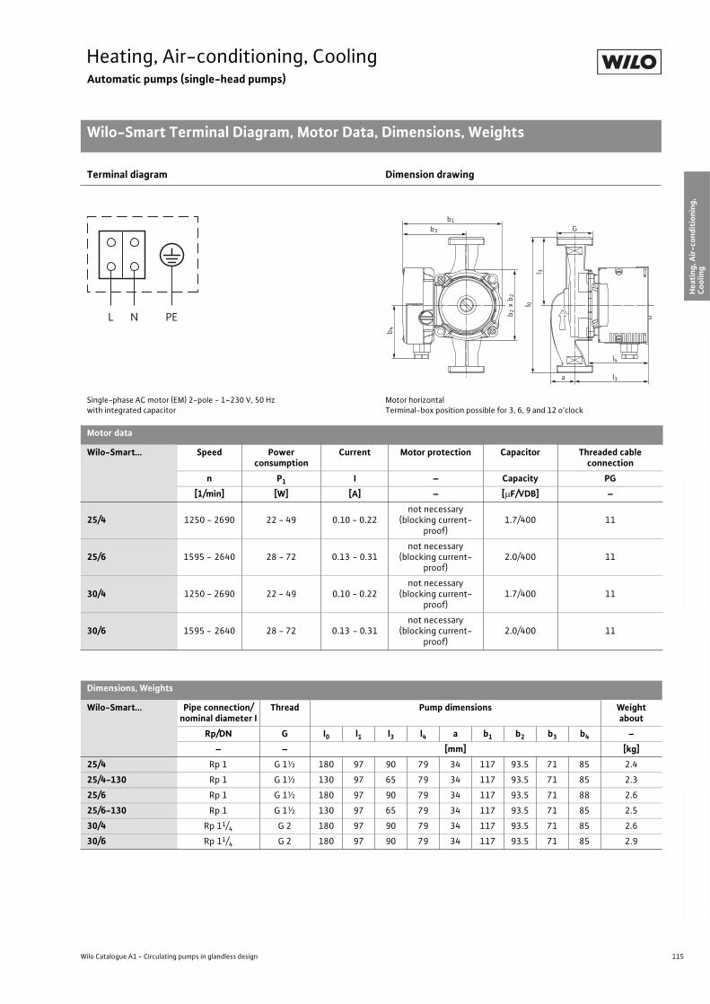
115
Heating, Air-conditioning, CoolingAutomatic pumps (single-head pumps)
Wilo-Smart Terminal Diagram, Motor Data, Dimensions, Weights
Wilo Catalogue A1 - Circulating pumps in glandless design
Hea
tin
g, A
ir-c
on
dit
ion
ing
, C
oo
ling
Po
tab
le w
ater
cir
cula
tio
nSo
lar
ther
mal
Serv
ice/
Acc
esso
ries
, Sys
tem
sSw
itch
gea
rs a
nd
Co
ntr
ol
Dev
ices
P
um
p M
anag
emen
t S y
stem
s
Terminal diagram Dimension drawing
Single-phase AC motor (EM) 2-pole - 1~230 V, 50 Hzwith integrated capacitor
Motor horizontalTerminal-box position possible for 3, 6, 9 and 12 o’clock
Motor data
Wilo-Smart... Speed Power consumption
Current Motor protection Capacitor Threaded cable connection
n P1 I – Capacity PG
[1/min] [W] [A] – [ F/VDB] –
25/4 1250 - 2690 22 - 49 0.10 - 0.22not necessary
(blocking current-proof)
1.7/400 11
25/6 1595 - 2640 28 - 72 0.13 - 0.31not necessary
(blocking current-proof)
2.0/400 11
30/4 1250 - 2690 22 - 49 0.10 - 0.22not necessary
(blocking current-proof)
1.7/400 11
30/6 1595 - 2640 28 - 72 0.13 - 0.31not necessary
(blocking current-proof)
2.0/400 11
Dimensions, Weights
Wilo-Smart... Pipe connection/nominal diameter I
Thread Pump dimensions Weightabout
Rp/DN G I0 l1 l3 l4 a b1 b2 b3 b4 –
– – [mm] [kg]
25/4 Rp 1 G 1½ 180 97 90 79 34 117 93.5 71 85 2.4
25/4-130 Rp 1 G 1½ 130 97 65 79 34 117 93.5 71 85 2.3
25/6 Rp 1 G 1½ 180 97 90 79 34 117 93.5 71 88 2.6
25/6-130 Rp 1 G 1½ 130 97 65 79 34 117 93.5 71 85 2.5
30/4 Rp 11/4 G 2 180 97 90 79 34 117 93.5 71 85 2.6
30/6 Rp 11/4 G 2 180 97 90 79 34 117 93.5 71 85 2.9
L N PE
b1
b3 G
b4
l 3
l4
l1a
l 0
b2
b2
x
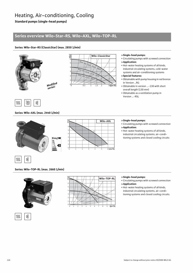
116 Subject to change without prior notice 09/2006 WILO AG
Heating, Air-conditioning, CoolingStandard pumps (single-head pumps)
Series overview Wilo-Star-RS, Wilo-AXL, Wilo-TOP-RL
Series: Wilo-Star-RS (ClassicStar) (max. 2850 1/min)
>Single-head pumps:• Circulating pumps with screwed connection
>Application:• Hot-water heating systems of all kinds,
industrial circulating systems, cold-water
systems and air-conditioning systems
>Special features:• Obtainable with pump housing in red bronze
in Version …RG
• Obtainable in version …-130 with short
overall length (130 mm)
• Obtainable as a ventilation pump in
Version …-RSL
Series: Wilo-AXL (max. 2440 1/min)
>Single-head pumps:• Circulating pumps with screwed connection
>Application:• Hot-water heating systems of all kinds,
industrial circulating systems, air-condi-
tioning systems and closed cooling circuits
Series: Wilo-TOP-RL (max. 2660 1/min)
>Single-head pumps:• Circulating pumps with screwed connection
>Application:• Hot-water heating systems of all kinds,
industrial circulating systems, air-condi-
tioning systems and closed cooling circuits.
Modified
series!
0,5 10 1,5 2 3
4
5
6
3
2
1
0
H[m
]
Wilo-ClassicStar
Q[m³/h]
Star-RS 15/6, 25/6, 30/6 Star-RS 15/4, 25/4, 30/4Star-RS 25/2, 30/2
6
5
4
3
1
2
00 1 3 42 65 Q [m3/h]
H [m
]
Wilo-AXL
2
1
Q[m3/h]0 1 2 3 4 5 6 7 8 9
H [m
]
6
5
4
3
2
1
0
Wilo-TOP-RL
30/4
30/7,5
25/7,5
30/6,5
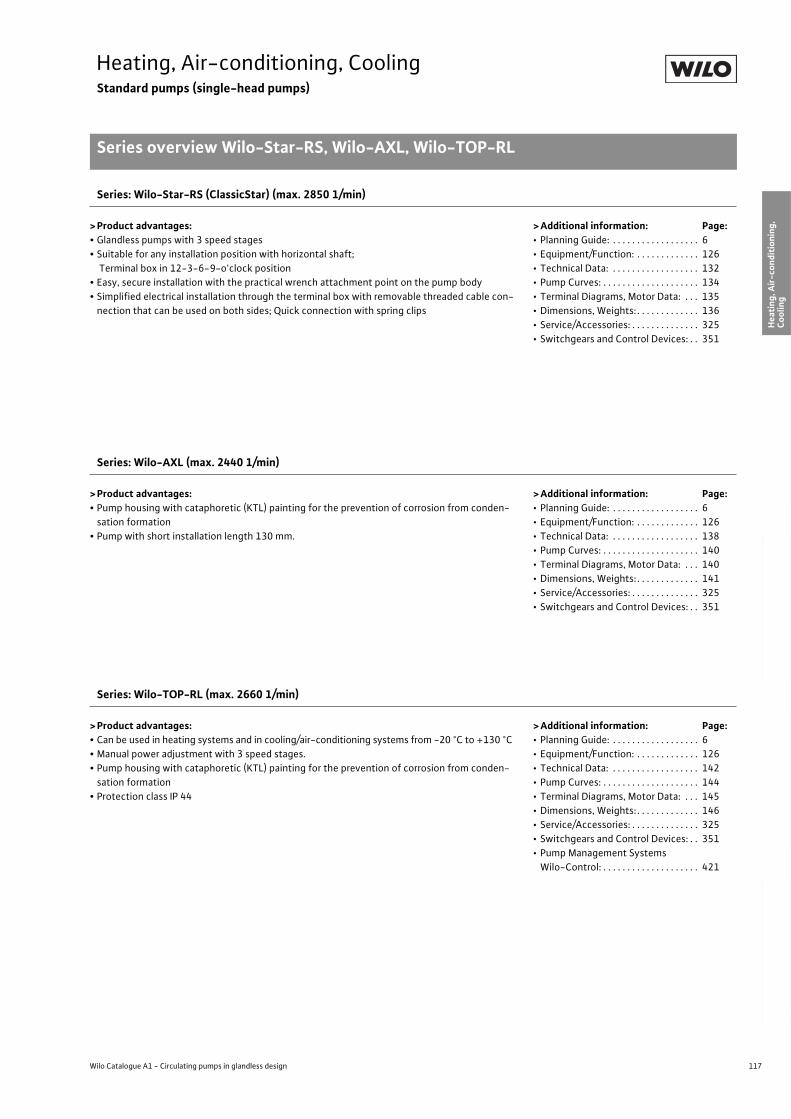
117
Heating, Air-conditioning, CoolingStandard pumps (single-head pumps)
Series overview Wilo-Star-RS, Wilo-AXL, Wilo-TOP-RL
Wilo Catalogue A1 - Circulating pumps in glandless design
Hea
tin
g, A
ir-c
on
dit
ion
ing
, C
oo
ling
Po
tab
le w
ater
cir
cula
tio
nSo
lar
ther
mal
Serv
ice/
Acc
esso
ries
, Sys
tem
sSw
itch
gea
rs a
nd
Co
ntr
ol
Dev
ices
P
um
p M
anag
emen
t S y
stem
s
Series: Wilo-Star-RS (ClassicStar) (max. 2850 1/min)
> Product advantages:• Glandless pumps with 3 speed stages
• Suitable for any installation position with horizontal shaft;
Terminal box in 12-3-6-9-o'clock position
• Easy, secure installation with the practical wrench attachment point on the pump body
• Simplified electrical installation through the terminal box with removable threaded cable con-
nection that can be used on both sides; Quick connection with spring clips
> Additional information: Page:• Planning Guide: . . . . . . . . . . . . . . . . . . 6
• Equipment/Function: . . . . . . . . . . . . . 126
• Technical Data: . . . . . . . . . . . . . . . . . . 132
• Pump Curves: . . . . . . . . . . . . . . . . . . . . 134
• Terminal Diagrams, Motor Data: . . . 135
• Dimensions, Weights: . . . . . . . . . . . . . 136
• Service/Accessories: . . . . . . . . . . . . . . 325
• Switchgears and Control Devices: . . 351
Series: Wilo-AXL (max. 2440 1/min)
> Product advantages:• Pump housing with cataphoretic (KTL) painting for the prevention of corrosion from conden-
sation formation
• Pump with short installation length 130 mm.
> Additional information: Page:• Planning Guide: . . . . . . . . . . . . . . . . . . 6
• Equipment/Function: . . . . . . . . . . . . . 126
• Technical Data: . . . . . . . . . . . . . . . . . . 138
• Pump Curves: . . . . . . . . . . . . . . . . . . . . 140
• Terminal Diagrams, Motor Data: . . . 140
• Dimensions, Weights: . . . . . . . . . . . . . 141
• Service/Accessories: . . . . . . . . . . . . . . 325
• Switchgears and Control Devices: . . 351
Series: Wilo-TOP-RL (max. 2660 1/min)
> Product advantages:• Can be used in heating systems and in cooling/air-conditioning systems from -20 °C to +130 °C
• Manual power adjustment with 3 speed stages.
• Pump housing with cataphoretic (KTL) painting for the prevention of corrosion from conden-
sation formation
• Protection class IP 44
> Additional information: Page:• Planning Guide: . . . . . . . . . . . . . . . . . . 6
• Equipment/Function: . . . . . . . . . . . . . 126
• Technical Data: . . . . . . . . . . . . . . . . . . 142
• Pump Curves: . . . . . . . . . . . . . . . . . . . . 144
• Terminal Diagrams, Motor Data: . . . 145
• Dimensions, Weights: . . . . . . . . . . . . . 146
• Service/Accessories: . . . . . . . . . . . . . . 325
• Switchgears and Control Devices: . . 351
• Pump Management Systems
Wilo-Control: . . . . . . . . . . . . . . . . . . . . 421
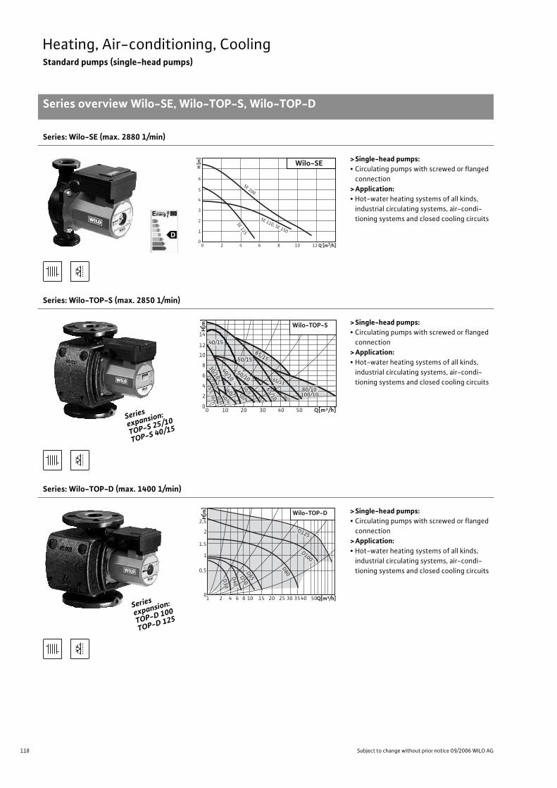
118 Subject to change without prior notice 09/2006 WILO AG
Heating, Air-conditioning, CoolingStandard pumps (single-head pumps)
Series overview Wilo-SE, Wilo-TOP-S, Wilo-TOP-D
Series: Wilo-SE (max. 2880 1/min)
>Single-head pumps:• Circulating pumps with screwed or flanged
connection
>Application:• Hot-water heating systems of all kinds,
industrial circulating systems, air-condi-
tioning systems and closed cooling circuits
Series: Wilo-TOP-S (max. 2850 1/min)
>Single-head pumps:• Circulating pumps with screwed or flanged
connection
>Application:• Hot-water heating systems of all kinds,
industrial circulating systems, air-condi-
tioning systems and closed cooling circuits
Series: Wilo-TOP-D (max. 1400 1/min)
>Single-head pumps:• Circulating pumps with screwed or flanged
connection
>Application:• Hot-water heating systems of all kinds,
industrial circulating systems, air-condi-
tioning systems and closed cooling circuits
6
5
4
3
1
2
00 2 6 84 10 12 Q [m3/h]
H [m
]
Wilo-SE
SE 200
SE 12
5
SE 110, SE 150
Series
expansion
:
TOP-S 25/
10
TOP-S 40/
15
30
/10
65
/1065/7
80/7
Q[m³/h]
H[m
]
14
12
50/15
65/15
65/13
50/10
40/7
50
/7
50/4
40/4
30
/4
25
/5, 3
0/5
25
/7,3
0/7
80/10100/10
10
8
6
4
2
00 10 20 30 40 50
Wilo-TOP-S
40/15
40/10
Series
expansion
:
TOP-D 100
TOP-D 125
Wilo-TOP-D
10
0,5
1,5
2,5
2
H[m
]
1
2 4 6 8 10 15 20 25 30 3540 50Q[m³/h]
D125
D8
0D6
5D5
0
D4
0
D3
0
D100
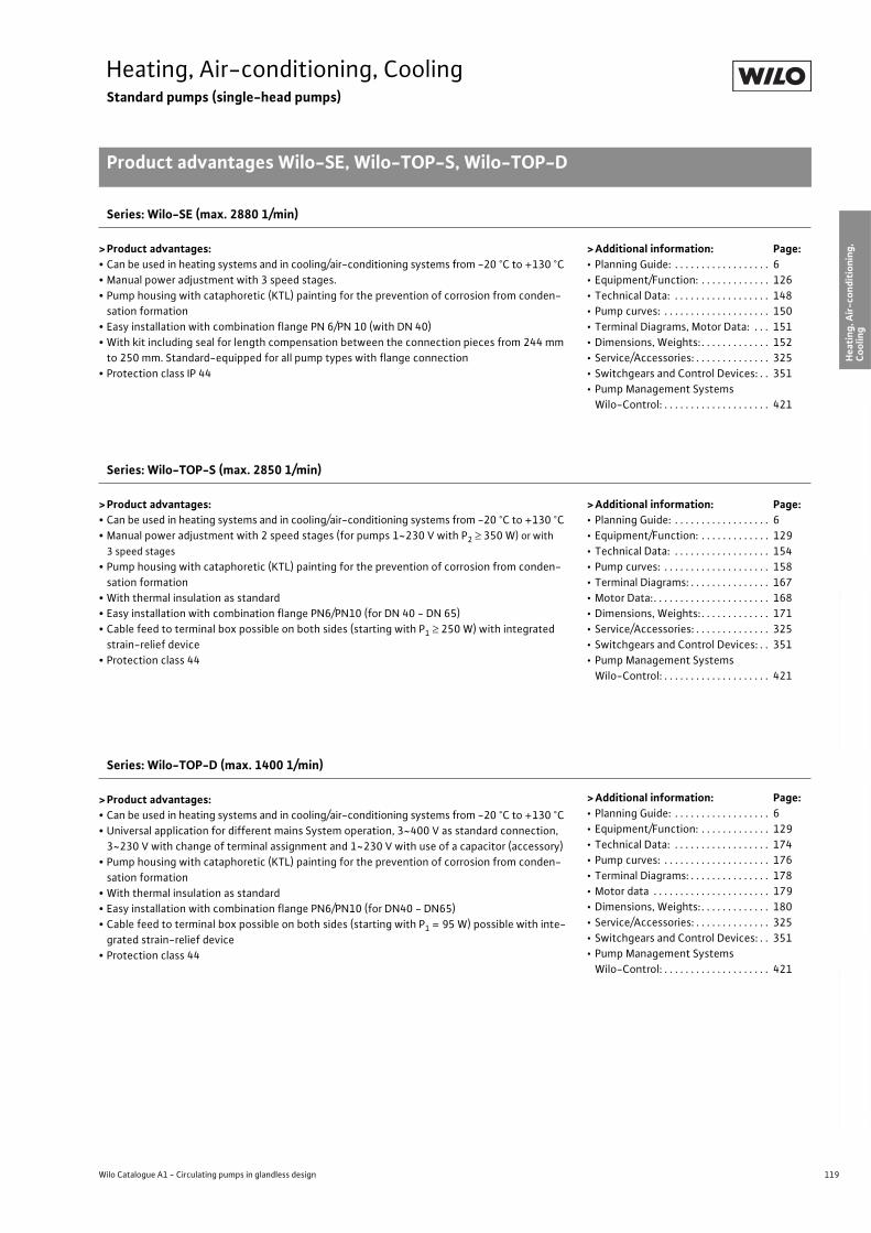
119
Heating, Air-conditioning, CoolingStandard pumps (single-head pumps)
Product advantages Wilo-SE, Wilo-TOP-S, Wilo-TOP-D
Wilo Catalogue A1 - Circulating pumps in glandless design
Hea
tin
g, A
ir-c
on
dit
ion
ing
, C
oo
ling
Po
tab
le w
ater
cir
cula
tio
nSo
lar
ther
mal
Serv
ice/
Acc
esso
ries
, Sys
tem
sSw
itch
gea
rs a
nd
Co
ntr
ol
Dev
ices
P
um
p M
anag
emen
t S y
stem
s
Series: Wilo-SE (max. 2880 1/min)
> Product advantages:• Can be used in heating systems and in cooling/air-conditioning systems from -20 °C to +130 °C
• Manual power adjustment with 3 speed stages.
• Pump housing with cataphoretic (KTL) painting for the prevention of corrosion from conden-
sation formation
• Easy installation with combination flange PN 6/PN 10 (with DN 40)
• With kit including seal for length compensation between the connection pieces from 244 mm
to 250 mm. Standard-equipped for all pump types with flange connection
• Protection class IP 44
> Additional information: Page:• Planning Guide: . . . . . . . . . . . . . . . . . . 6
• Equipment/Function: . . . . . . . . . . . . . 126
• Technical Data: . . . . . . . . . . . . . . . . . . 148
• Pump curves: . . . . . . . . . . . . . . . . . . . . 150
• Terminal Diagrams, Motor Data: . . . 151
• Dimensions, Weights: . . . . . . . . . . . . . 152
• Service/Accessories: . . . . . . . . . . . . . . 325
• Switchgears and Control Devices: . . 351
• Pump Management Systems
Wilo-Control: . . . . . . . . . . . . . . . . . . . . 421
Series: Wilo-TOP-S (max. 2850 1/min)
> Product advantages:• Can be used in heating systems and in cooling/air-conditioning systems from -20 °C to +130 °C
• Manual power adjustment with 2 speed stages (for pumps 1~230 V with P2 350 W) or with
3 speed stages
• Pump housing with cataphoretic (KTL) painting for the prevention of corrosion from conden-
sation formation
• With thermal insulation as standard
• Easy installation with combination flange PN6/PN10 (for DN 40 - DN 65)
• Cable feed to terminal box possible on both sides (starting with P1 250 W) with integrated
strain-relief device
• Protection class 44
> Additional information: Page:• Planning Guide: . . . . . . . . . . . . . . . . . . 6
• Equipment/Function: . . . . . . . . . . . . . 129
• Technical Data: . . . . . . . . . . . . . . . . . . 154
• Pump curves: . . . . . . . . . . . . . . . . . . . . 158
• Terminal Diagrams: . . . . . . . . . . . . . . . 167
• Motor Data:. . . . . . . . . . . . . . . . . . . . . . 168
• Dimensions, Weights: . . . . . . . . . . . . . 171
• Service/Accessories: . . . . . . . . . . . . . . 325
• Switchgears and Control Devices: . . 351
• Pump Management Systems
Wilo-Control: . . . . . . . . . . . . . . . . . . . . 421
Series: Wilo-TOP-D (max. 1400 1/min)
> Product advantages:• Can be used in heating systems and in cooling/air-conditioning systems from -20 °C to +130 °C
• Universal application for different mains System operation, 3~400 V as standard connection,
3~230 V with change of terminal assignment and 1~230 V with use of a capacitor (accessory)
• Pump housing with cataphoretic (KTL) painting for the prevention of corrosion from conden-
sation formation
• With thermal insulation as standard
• Easy installation with combination flange PN6/PN10 (for DN40 - DN65)
• Cable feed to terminal box possible on both sides (starting with P1 = 95 W) possible with inte-
grated strain-relief device
• Protection class 44
> Additional information: Page:• Planning Guide: . . . . . . . . . . . . . . . . . . 6
• Equipment/Function: . . . . . . . . . . . . . 129
• Technical Data: . . . . . . . . . . . . . . . . . . 174
• Pump curves: . . . . . . . . . . . . . . . . . . . . 176
• Terminal Diagrams: . . . . . . . . . . . . . . . 178
• Motor data . . . . . . . . . . . . . . . . . . . . . . 179
• Dimensions, Weights: . . . . . . . . . . . . . 180
• Service/Accessories: . . . . . . . . . . . . . . 325
• Switchgears and Control Devices: . . 351
• Pump Management Systems
Wilo-Control: . . . . . . . . . . . . . . . . . . . . 421
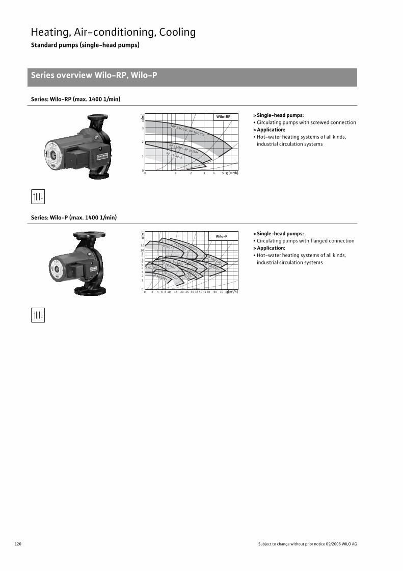
120 Subject to change without prior notice 09/2006 WILO AG
Heating, Air-conditioning, CoolingStandard pumps (single-head pumps)
Series overview Wilo-RP, Wilo-P
Series: Wilo-RP (max. 1400 1/min)
>Single-head pumps:• Circulating pumps with screwed connection
>Application:• Hot-water heating systems of all kinds,
industrial circulation systems
Series: Wilo-P (max. 1400 1/min)
>Single-head pumps:• Circulating pumps with flanged connection
>Application:• Hot-water heating systems of all kinds,
industrial circulation systems
0 1 2 3 4 5 Q[m3/h]0
1
2
3
RP 25/60-2
RP 25/80r, RP 30/80r
RP 25/100r, RP 30/100r
Wilo-RP
[m
]H
0 2 4 6 8 10 15 20 25 30 35 40 45 50 60 70 Q[m3/h]0
1
10
23456789
12 P 50/250 r P 65/250 r
P 100/200 r
P 80/250 r
P 100/160 r
P 80/160 r
P 65/160 r P 50/160 r P 80/125 r P65/ 125r
P 50/125 r
P 40/160 r
P 40/100 r
Wilo-P [m
]H
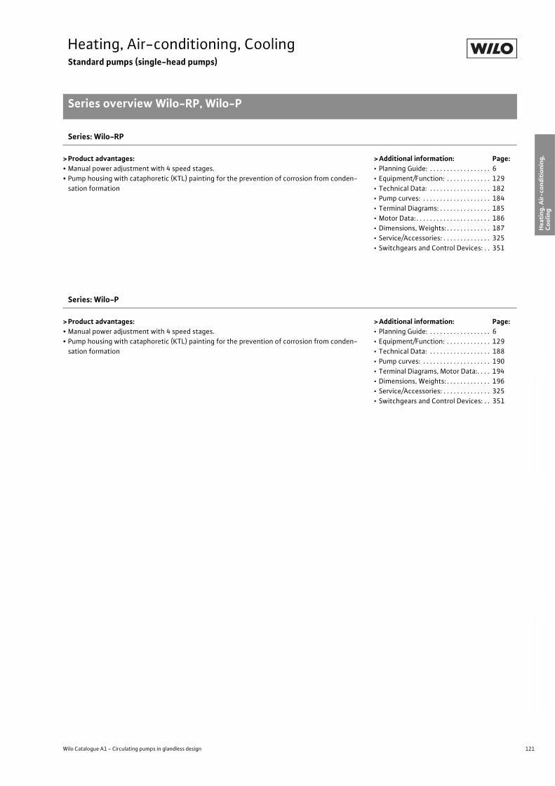
121
Heating, Air-conditioning, CoolingStandard pumps (single-head pumps)
Series overview Wilo-RP, Wilo-P
Wilo Catalogue A1 - Circulating pumps in glandless design
Hea
tin
g, A
ir-c
on
dit
ion
ing
, C
oo
ling
Po
tab
le w
ater
cir
cula
tio
nSo
lar
ther
mal
Serv
ice/
Acc
esso
ries
, Sys
tem
sSw
itch
gea
rs a
nd
Co
ntr
ol
Dev
ices
P
um
p M
anag
emen
t S y
stem
s
Series: Wilo-RP
> Product advantages:• Manual power adjustment with 4 speed stages.
• Pump housing with cataphoretic (KTL) painting for the prevention of corrosion from conden-
sation formation
>Additional information: Page:• Planning Guide: . . . . . . . . . . . . . . . . . . 6
• Equipment/Function: . . . . . . . . . . . . . 129
• Technical Data: . . . . . . . . . . . . . . . . . . 182
• Pump curves: . . . . . . . . . . . . . . . . . . . . 184
• Terminal Diagrams: . . . . . . . . . . . . . . . 185
• Motor Data: . . . . . . . . . . . . . . . . . . . . . . 186
• Dimensions, Weights: . . . . . . . . . . . . . 187
• Service/Accessories: . . . . . . . . . . . . . . 325
• Switchgears and Control Devices: . . 351
Series: Wilo-P
> Product advantages:• Manual power adjustment with 4 speed stages.
• Pump housing with cataphoretic (KTL) painting for the prevention of corrosion from conden-
sation formation
>Additional information: Page:• Planning Guide: . . . . . . . . . . . . . . . . . . 6
• Equipment/Function: . . . . . . . . . . . . . 129
• Technical Data: . . . . . . . . . . . . . . . . . . 188
• Pump curves: . . . . . . . . . . . . . . . . . . . . 190
• Terminal Diagrams, Motor Data:. . . . 194
• Dimensions, Weights: . . . . . . . . . . . . . 196
• Service/Accessories: . . . . . . . . . . . . . . 325
• Switchgears and Control Devices: . . 351
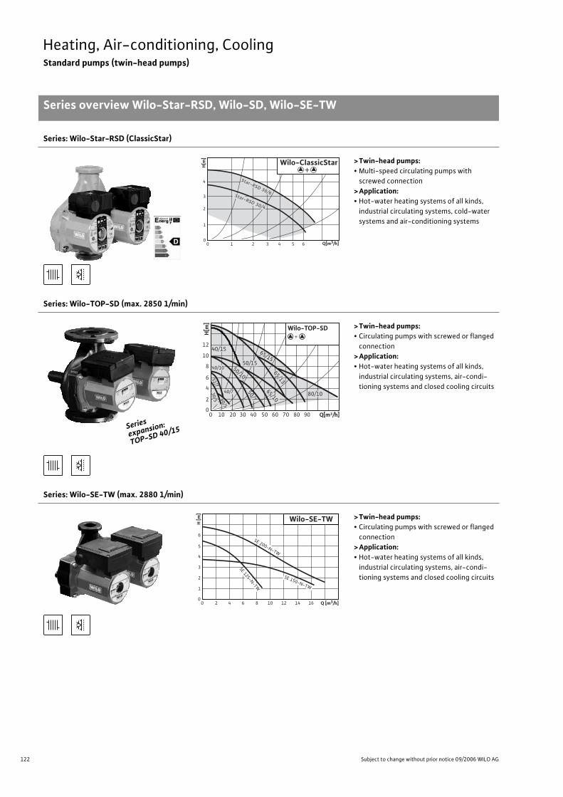
122 Subject to change without prior notice 09/2006 WILO AG
Heating, Air-conditioning, CoolingStandard pumps (twin-head pumps)
Series overview Wilo-Star-RSD, Wilo-SD, Wilo-SE-TW
Series: Wilo-Star-RSD (ClassicStar)
>Twin-head pumps:• Multi-speed circulating pumps with
screwed connection
>Application:• Hot-water heating systems of all kinds,
industrial circulating systems, cold-water
systems and air-conditioning systems
Series: Wilo-TOP-SD (max. 2850 1/min)
>Twin-head pumps:• Circulating pumps with screwed or flanged
connection
>Application:• Hot-water heating systems of all kinds,
industrial circulating systems, air-condi-
tioning systems and closed cooling circuits
Series: Wilo-SE-TW (max. 2880 1/min)
>Twin-head pumps:• Circulating pumps with screwed or flanged
connection
>Application:• Hot-water heating systems of all kinds,
industrial circulating systems, air-condi-
tioning systems and closed cooling circuits
0 1 2 3 4 5 60
1
2
3
4 Star-RSD 30/6Star-RSD 30/4
Wilo-ClassicStar
Q[m3/h]
H[m
]
+
Series
expansion
:
TOP-SD 40
/15
0 10 20 30 40 50 60 70 80 90 0
2
4
6
8
10
12
80/10
40/10
40/7 50
/7
32
/7
65/10
65/13
65/15
40
/3
30
/5
Q[m³/h]
H[m
]
+
40/15
50/15
Wilo-TOP-SD
50/10
6
5
4
3
1
2
00 2 6 84 10 12 14 16 Q [m3/h]
H [m
]
Wilo-SE-TW
SE 200-N-TW
SE 150-N-TW
SE 125-N-TW
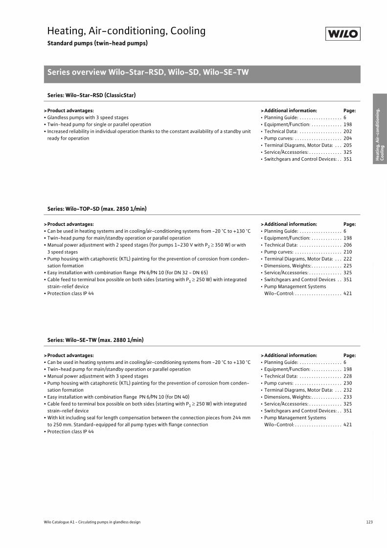
123
Heating, Air-conditioning, CoolingStandard pumps (twin-head pumps)
Series overview Wilo-Star-RSD, Wilo-SD, Wilo-SE-TW
Wilo Catalogue A1 - Circulating pumps in glandless design
Hea
tin
g, A
ir-c
on
dit
ion
ing
, C
oo
ling
Po
tab
le w
ater
cir
cula
tio
nSo
lar
ther
mal
Serv
ice/
Acc
esso
ries
, Sys
tem
sSw
itch
gea
rs a
nd
Co
ntr
ol
Dev
ices
P
um
p M
anag
emen
t S y
stem
s
Series: Wilo-Star-RSD (ClassicStar)
> Product advantages:• Glandless pumps with 3 speed stages
• Twin-head pump for single or parallel operation
• Increased reliability in individual operation thanks to the constant availability of a standby unit
ready for operation
> Additional information: Page:• Planning Guide: . . . . . . . . . . . . . . . . . . 6
• Equipment/Function: . . . . . . . . . . . . . 198
• Technical Data: . . . . . . . . . . . . . . . . . . 202
• Pump curves: . . . . . . . . . . . . . . . . . . . . 204
• Terminal Diagrams, Motor Data: . . . 205
• Service/Accessories: . . . . . . . . . . . . . . 325
• Switchgears and Control Devices: . . 351
Series: Wilo-TOP-SD (max. 2850 1/min)
> Product advantages:• Can be used in heating systems and in cooling/air-conditioning systems from -20 °C to +130 °C
• Twin-head pump for main/standby operation or parallel operation
• Manual power adjustment with 2 speed stages (for pumps 1~230 V with P2 350 W) or with
3 speed stages
• Pump housing with cataphoretic (KTL) painting for the prevention of corrosion from conden-
sation formation
• Easy installation with combination flange PN 6/PN 10 (for DN 32 - DN 65)
• Cable feed to terminal box possible on both sides (starting with P1 250 W) with integrated
strain-relief device
• Protection class IP 44
> Additional information: Page:• Planning Guide: . . . . . . . . . . . . . . . . . . 6
• Equipment/Function: . . . . . . . . . . . . . 198
• Technical Data: . . . . . . . . . . . . . . . . . . 206
• Pump curves: . . . . . . . . . . . . . . . . . . . . 210
• Terminal Diagrams, Motor Data: . . . 222
• Dimensions, Weights: . . . . . . . . . . . . . 225
• Service/Accessories: . . . . . . . . . . . . . . 325
• Switchgears and Control Devices . . 351
• Pump Management Systems
Wilo-Control: . . . . . . . . . . . . . . . . . . . . 421
Series: Wilo-SE-TW (max. 2880 1/min)
> Product advantages:• Can be used in heating systems and in cooling/air-conditioning systems from -20 °C to +130 °C
• Twin-head pump for main/standby operation or parallel operation
• Manual power adjustment with 3 speed stages
• Pump housing with cataphoretic (KTL) painting for the prevention of corrosion from conden-
sation formation
• Easy installation with combination flange PN 6/PN 10 (for DN 40)
• Cable feed to terminal box possible on both sides (starting with P1 250 W) with integrated
strain-relief device
• With kit including seal for length compensation between the connection pieces from 244 mm
to 250 mm. Standard-equipped for all pump types with flange connection
• Protection class IP 44
> Additional information: Page:• Planning Guide: . . . . . . . . . . . . . . . . . . 6
• Equipment/Function: . . . . . . . . . . . . . 198
• Technical Data: . . . . . . . . . . . . . . . . . . 228
• Pump curves: . . . . . . . . . . . . . . . . . . . . 230
• Terminal Diagrams, Motor Data: . . . 232
• Dimensions, Weights: . . . . . . . . . . . . . 233
• Service/Accessories: . . . . . . . . . . . . . . 325
• Switchgears and Control Devices: . . 351
• Pump Management Systems
Wilo-Control: . . . . . . . . . . . . . . . . . . . . 421
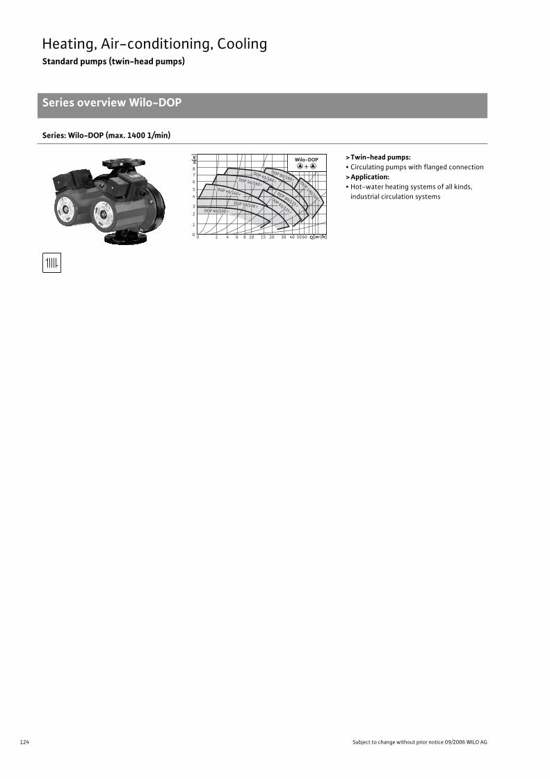
124 Subject to change without prior notice 09/2006 WILO AG
Heating, Air-conditioning, CoolingStandard pumps (twin-head pumps)
Series overview Wilo-DOP
Series: Wilo-DOP (max. 1400 1/min)
>Twin-head pumps:• Circulating pumps with flanged connection
>Application:• Hot-water heating systems of all kinds,
industrial circulation systems
0 2 4 6 8 10 15 20 30 40 5060 Q[m3/h]0
1
2
3
4
5
6
78
[m
]H
DOP 80/160 r
DOP 65/160 r DOP 100/160 r
DOP 80/125 r
DOP 65/125 r
DOP 50/160 r DOP 40/160 r
DOP 50/100 r DOP 40/100 r
Wilo-DOP+
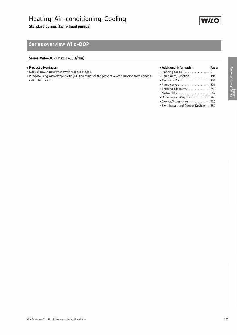
125
Heating, Air-conditioning, CoolingStandard pumps (twin-head pumps)
Series overview Wilo-DOP
Wilo Catalogue A1 - Circulating pumps in glandless design
Hea
tin
g, A
ir-c
on
dit
ion
ing
, C
oo
ling
Po
tab
le w
ater
cir
cula
tio
nSo
lar
ther
mal
Serv
ice/
Acc
esso
ries
, Sys
tem
sSw
itch
gea
rs a
nd
Co
ntr
ol
Dev
ices
P
um
p M
anag
emen
t S y
stem
s
Series: Wilo-DOP (max. 1400 1/min)
> Product advantages:• Manual power adjustment with 4 speed stages.
• Pump housing with cataphoretic (KTL) painting for the prevention of corrosion from conden-
sation formation
> Additional information: Page:• Planning Guide: . . . . . . . . . . . . . . . . . . 6
• Equipment/Function: . . . . . . . . . . . . . 198
• Technical Data: . . . . . . . . . . . . . . . . . . 234
• Pump curves: . . . . . . . . . . . . . . . . . . . . 236
• Terminal Diagrams: . . . . . . . . . . . . . . . 241
• Motor Data:. . . . . . . . . . . . . . . . . . . . . . 242
• Dimensions, Weights: . . . . . . . . . . . . . 243
• Service/Accessories: . . . . . . . . . . . . . . 325
• Switchgears and Control Devices: . . 351
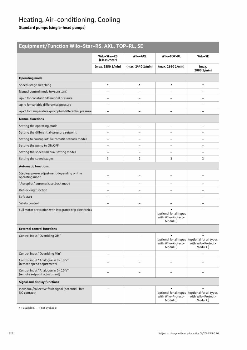
126 Subject to change without prior notice 09/2006 WILO AG
Heating, Air-conditioning, CoolingStandard pumps (single-head pumps)
Equipment/Function Wilo-Star-RS, AXL, TOP-RL, SE
Wilo-Star-RS(ClassicStar)
Wilo-AXL Wilo-TOP-RL Wilo-SE
(max. 2850 1/min) (max. 2440 1/min) (max. 2660 1/min) (max. 2880 1/min)
Operating mode
Speed-stage switching • • • •
Manual control mode (n=constant) – – – –
p-c for constant differential pressure – – – –
p-v for variable differential pressure – – – –
p-T for temperature-prompted differential pressure – – – –
Manual functions
Setting the operating mode – – – –
Setting the differential-pressure setpoint – – – –
Setting to “Autopilot” (automatic setback mode) – – – –
Setting the pump to ON/OFF – – – –
Setting the speed (manual setting mode) – – – –
Setting the speed stages 3 2 3 3
Automatic functions
Stepless power adjustment depending on the operating mode
– – – –
“Autopilot” automatic setback mode – – – –
Deblocking function – – – –
Soft start – – – –
Safety control – – – –
Full motor protection with integrated trip electronics – – •(optional for all types with Wilo-Protect-
Modul C)
–
External control functions
Control input “Overriding Off” – – •(optional for all types with Wilo-Protect-
Modul C)
•(optional for all types with Wilo-Protect-
Modul C)
Control input “Overriding Min” – – – –
Control input “Analogue in 0- 10 V” (remote speed adjustment)
– – – –
Control input “Analogue in 0- 10 V” (remote setpoint adjustment)
– – – –
Signal and display functions
Individual/collective fault signal (potential-free NC contact)
– – •(optional for all types with Wilo-Protect-
Modul C)
•(optional for all types with Wilo-Protect-
Modul C)
• = available, – = not available

127
Heating, Air-conditioning, CoolingStandard pumps (single-head pumps)
Equipment/Function Wilo-Star-RS, AXL, TOP-RL, SE
Wilo Catalogue A1 - Circulating pumps in glandless design
Hea
tin
g, A
ir-c
on
dit
ion
ing
, C
oo
ling
Po
tab
le w
ater
cir
cula
tio
nSo
lar
ther
mal
Serv
ice/
Acc
esso
ries
, Sys
tem
sSw
itch
gea
rs a
nd
Co
ntr
ol
Dev
ices
P
um
p M
anag
emen
t S y
stem
s
Signal and display functions (Continued)
Collective fault signal (potential-free NC contact) – – •(optional for all types with Wilo-Protect-
Modul C)
•(optional for all types with Wilo-Protect-
Modul C)
Individual run signal (potential-free NO contact) – – •(optional for all types with Wilo-Protect-
Modul C)
•(optional for all types with Wilo-Protect-
Modul C)
Thermal winding contact (WSK, potential-free NC contact)
– – – –
Fault light – – •(optional for all types with Wilo-Protect-
Modul C)
•(optional for all types with Wilo-Protect-
Modul C)
Direction-of-rotation telltale lamp – – – –
LC display for showing pump data and fault codes – – – –
Data exchange
Infrared interface for wireless data exchange with IR-Monitor (see function table for IR-Monitor)
– – – –
PLR serial digital interface for connection to BA via Wilo interface converter or company-specific coupling modules
– – – –
Serial digital LON interface for connection to a LONWORKS network
– – – –
Twin-head pump management (twin-head pump or 2 single-head pumps)
Main/standby operation (automatic fault-actuated switchover/time-sensitive pump alteration)
– – •(optional for all types with Wilo-Protect-
Modul C)
•(optional for all types with Wilo-Protect-
Modul C)
Addition operation (efficiency-optimised peak-load cut-in and out)
– – – –
Equipment/Scope of delivery
Wrench attachment point on pump body • – – –
Double switchover valve in pump housing – – – –
Cable entry possible on both sides • – – –
Quick connection with spring clips • – – –
Integrated air extraction fitting for automatic rapid ventilator Rp 3/8
•(only in version RSL)
– – –
Plug-in slot for optional expansion with Wilo-IF-Moduls
– – – –
Blocking current-proof motor • – – –
Wilo-Star-RS(ClassicStar)
Wilo-AXL Wilo-TOP-RL Wilo-SE
(max. 2850 1/min) (max. 2440 1/min) (max. 2660 1/min) (max. 2880 1/min)
• = available, – = not available
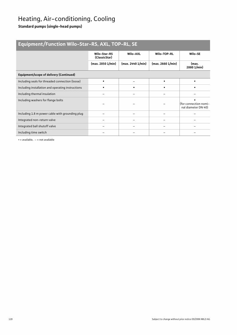
128 Subject to change without prior notice 09/2006 WILO AG
Heating, Air-conditioning, CoolingStandard pumps (single-head pumps)
Equipment/Function Wilo-Star-RS, AXL, TOP-RL, SE
Equipment/scope of delivery (Continued)
Including seals for threaded connection (loose) • – • •
Including installation and operating instructions • • • •
Including thermal insulation – – – –
Including washers for flange bolts– – –
•(for connection nomi-
nal diameter DN 40)
Including 1.8 m power cable with grounding plug – – – –
Integrated non-return valve – – – –
Integrated ball shutoff valve – – – –
Including time switch – – – –
Wilo-Star-RS(ClassicStar)
Wilo-AXL Wilo-TOP-RL Wilo-SE
(max. 2850 1/min) (max. 2440 1/min) (max. 2660 1/min) (max. 2880 1/min)
• = available, – = not available
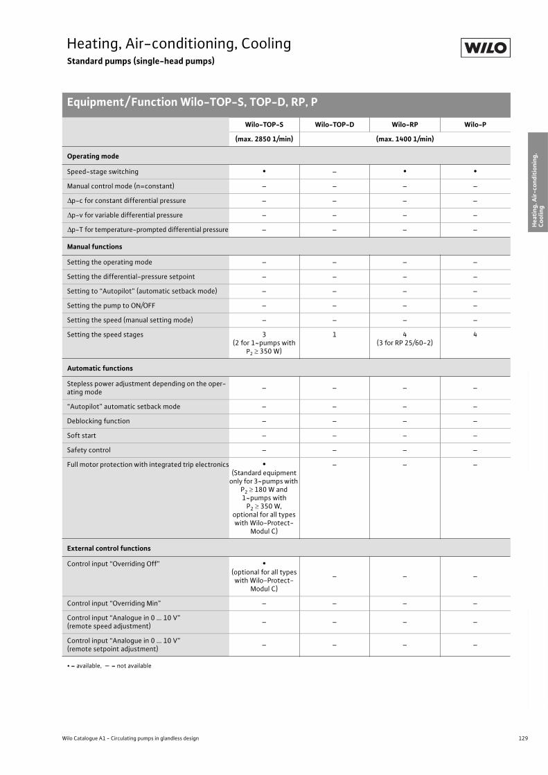
129
Heating, Air-conditioning, CoolingStandard pumps (single-head pumps)
Equipment/ Function Wilo-TOP-S, TOP-D, RP, P
Wilo Catalogue A1 - Circulating pumps in glandless design
Hea
tin
g, A
ir-c
on
dit
ion
ing
, C
oo
ling
Po
tab
le w
ater
cir
cula
tio
nSo
lar
ther
mal
Serv
ice/
Acc
esso
ries
, Sys
tem
sSw
itch
gea
rs a
nd
Co
ntr
ol
Dev
ices
P
um
p M
anag
emen
t S y
stem
s
Wilo-TOP-S Wilo-TOP-D Wilo-RP Wilo-P
(max. 2850 1/min) (max. 1400 1/min)
Operating mode
Speed-stage switching • – • •
Manual control mode (n=constant) – – – –
p-c for constant differential pressure – – – –
p-v for variable differential pressure – – – –
p-T for temperature-prompted differential pressure – – – –
Manual functions
Setting the operating mode – – – –
Setting the differential-pressure setpoint – – – –
Setting to “Autopilot” (automatic setback mode) – – – –
Setting the pump to ON/OFF – – – –
Setting the speed (manual setting mode) – – – –
Setting the speed stages 3(2 for 1~pumps with
P2 350 W)
1 4(3 for RP 25/60-2)
4
Automatic functions
Stepless power adjustment depending on the oper-ating mode
– – – –
“Autopilot” automatic setback mode – – – –
Deblocking function – – – –
Soft start – – – –
Safety control – – – –
Full motor protection with integrated trip electronics •(Standard equipment
only for 3~pumps with P2 180 W and 1~pumps with
P2 350 W,optional for all types with Wilo-Protect-
Modul C)
– – –
External control functions
Control input “Overriding Off” •(optional for all types with Wilo-Protect-
Modul C)
– – –
Control input “Overriding Min” – – – –
Control input “Analogue in 0 ... 10 V” (remote speed adjustment)
– – – –
Control input “Analogue in 0 ... 10 V” (remote setpoint adjustment)
– – – –
• = available, – = not available
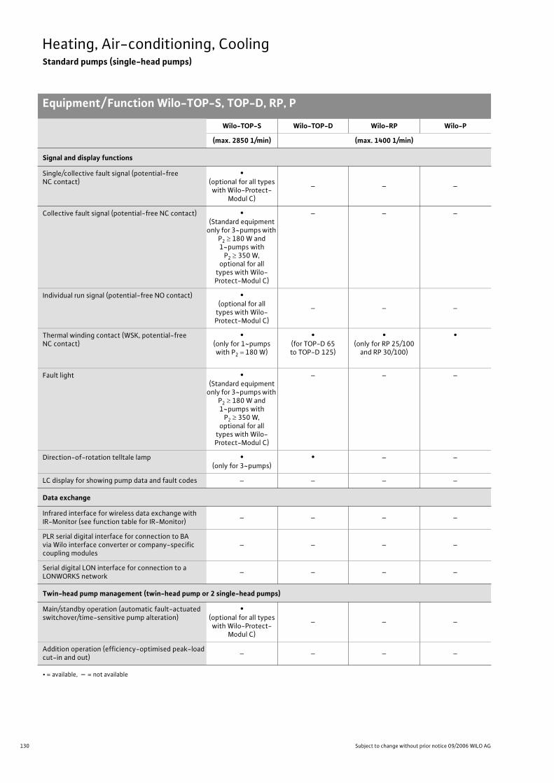
130 Subject to change without prior notice 09/2006 WILO AG
Heating, Air-conditioning, CoolingStandard pumps (single-head pumps)
Equipment/ Function Wilo-TOP-S, TOP-D, RP, P
Signal and display functions
Single/collective fault signal (potential-free NC contact)
•(optional for all types with Wilo-Protect-
Modul C)
– – –
Collective fault signal (potential-free NC contact) •(Standard equipment
only for 3~pumps with P2 180 W and 1~pumps with
P2 350 W,optional for all
types with Wilo-Protect-Modul C)
– – –
Individual run signal (potential-free NO contact) •(optional for all
types with Wilo-Protect-Modul C)
– – –
Thermal winding contact (WSK, potential-free NC contact)
•(only for 1~pumps with P2 180 W)
•(for TOP-D 65to TOP-D 125)
•(only for RP 25/100
and RP 30/100)
•
Fault light •(Standard equipment
only for 3~pumps with P2 180 W and 1~pumps with
P2 350 W,optional for all
types with Wilo-Protect-Modul C)
– – –
Direction-of-rotation telltale lamp •(only for 3~pumps)
• – –
LC display for showing pump data and fault codes – – – –
Data exchange
Infrared interface for wireless data exchange with IR-Monitor (see function table for IR-Monitor)
– – – –
PLR serial digital interface for connection to BA via Wilo interface converter or company-specific coupling modules
– – – –
Serial digital LON interface for connection to a LONWORKS network
– – – –
Twin-head pump management (twin-head pump or 2 single-head pumps)
Main/standby operation (automatic fault-actuated switchover/time-sensitive pump alteration)
•(optional for all types with Wilo-Protect-
Modul C)
– – –
Addition operation (efficiency-optimised peak-load cut-in and out)
– – – –
Wilo-TOP-S Wilo-TOP-D Wilo-RP Wilo-P
(max. 2850 1/min) (max. 1400 1/min)
• = available, – = not available
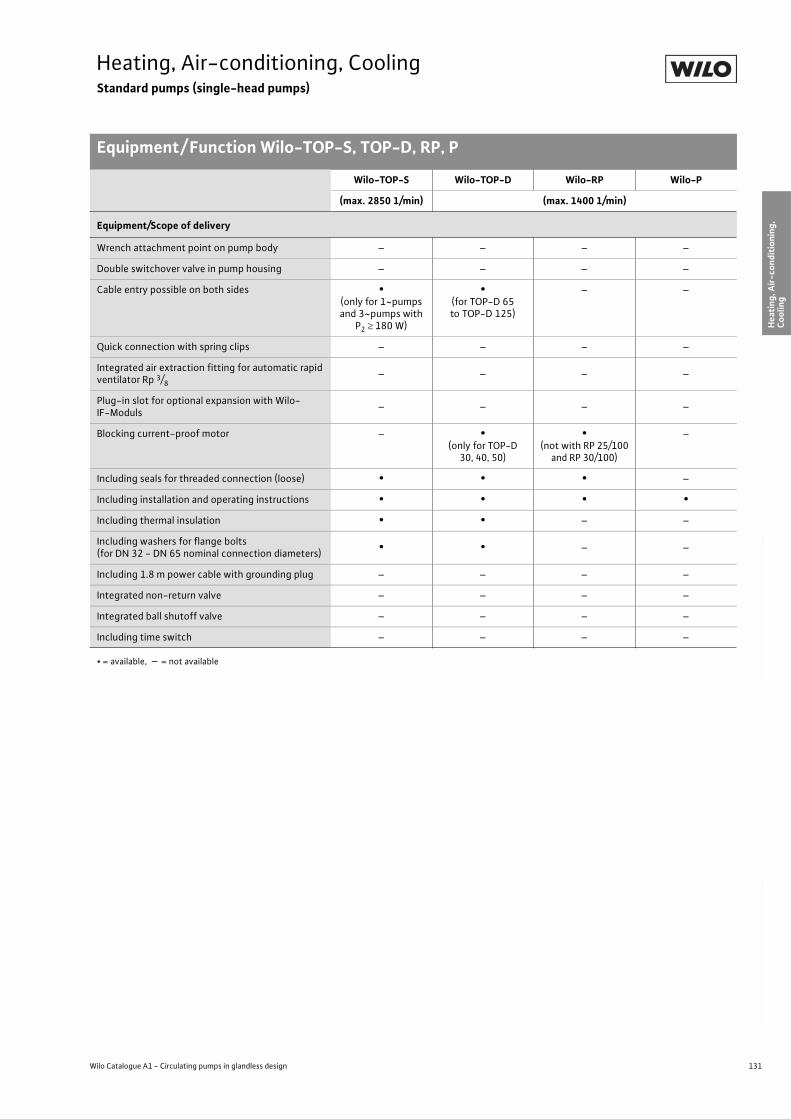
131
Heating, Air-conditioning, CoolingStandard pumps (single-head pumps)
Equipment/ Function Wilo-TOP-S, TOP-D, RP, P
Wilo Catalogue A1 - Circulating pumps in glandless design
Hea
tin
g, A
ir-c
on
dit
ion
ing
, C
oo
ling
Po
tab
le w
ater
cir
cula
tio
nSo
lar
ther
mal
Serv
ice/
Acc
esso
ries
, Sys
tem
sSw
itch
gea
rs a
nd
Co
ntr
ol
Dev
ices
P
um
p M
anag
emen
t S y
stem
s
Equipment/Scope of delivery
Wrench attachment point on pump body – – – –
Double switchover valve in pump housing – – – –
Cable entry possible on both sides •(only for 1~pumps and 3~pumps with
P2 180 W)
•(for TOP-D 65to TOP-D 125)
– –
Quick connection with spring clips – – – –
Integrated air extraction fitting for automatic rapid ventilator Rp 3/8
– – – –
Plug-in slot for optional expansion with Wilo-IF-Moduls
– – – –
Blocking current-proof motor – •(only for TOP-D
30, 40, 50)
•(not with RP 25/100
and RP 30/100)
–
Including seals for threaded connection (loose) • • • –
Including installation and operating instructions • • • •
Including thermal insulation • • – –
Including washers for flange bolts(for DN 32 - DN 65 nominal connection diameters)
• • – –
Including 1.8 m power cable with grounding plug – – – –
Integrated non-return valve – – – –
Integrated ball shutoff valve – – – –
Including time switch – – – –
Wilo-TOP-S Wilo-TOP-D Wilo-RP Wilo-P
(max. 2850 1/min) (max. 1400 1/min)
• = available, – = not available
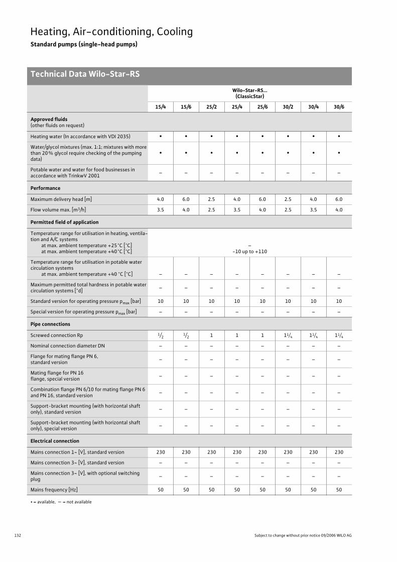
132 Subject to change without prior notice 09/2006 WILO AG
Heating, Air-conditioning, CoolingStandard pumps (single-head pumps)
Technical Data Wilo-Star-RS
Wilo-Star-RS...(ClassicStar)
15/4 15/6 25/2 25/4 25/6 30/2 30/4 30/6
Approved fluids(other fluids on request)
Heating water (In accordance with VDI 2035) • • • • • • • •
Water/glycol mixtures (max. 1:1; mixtures with more than 20% glycol require checking of the pumping data)
• • • • • • • •
Potable water and water for food businesses in accordance with TrinkwV 2001
– – – – – – – –
Performance
Maximum delivery head [m] 4.0 6.0 2.5 4.0 6.0 2.5 4.0 6.0
Flow volume max. [m3/h] 3.5 4.0 2.5 3.5 4.0 2.5 3.5 4.0
Permitted field of application
Temperature range for utilisation in heating, ventila-tion and A/C systems
at max. ambient temperature +25°C [°C]at max. ambient temperature +40°C [°C]
–-10 up to +110
Temperature range for utilisation in potable water circulation systems
at max. ambient temperature +40 °C [°C] – – – – – – – –
Maximum permitted total hardness in potable water circulation systems [°d]
– – – – – – – –
Standard version for operating pressure pmax [bar] 10 10 10 10 10 10 10 10
Special version for operating pressure pmax [bar] – – – – – – – –
Pipe connections
Screwed connection Rp 1/21/2 1 1 1 11/4 11/4 11/4
Nominal connection diameter DN – – – – – – – –
Flange for mating flange PN 6, standard version
– – – – – – – –
Mating flange for PN 16 flange, special version
– – – – – – – –
Combination flange PN 6/10 for mating flange PN 6 and PN 16, standard version
– – – – – – – –
Support-bracket mounting (with horizontal shaft only), standard version
– – – – – – – –
Support-bracket mounting (with horizontal shaft only), special version
– – – – – – – –
Electrical connection
Mains connection 1~ [V], standard version 230 230 230 230 230 230 230 230
Mains connection 3~ [V], standard version – – – – – – – –
Mains connection 3~ [V], with optional switching plug
– – – – – – – –
Mains frequency [Hz] 50 50 50 50 50 50 50 50
• = available, – = not available

133
Heating, Air-conditioning, CoolingStandard pumps (single-head pumps)
Technical Data Wilo-Star-RS
Wilo Catalogue A1 - Circulating pumps in glandless design
Hea
tin
g, A
ir-c
on
dit
ion
ing
, C
oo
ling
Po
tab
le w
ater
cir
cula
tio
nSo
lar
ther
mal
Serv
ice/
Acc
esso
ries
, Sys
tem
sSw
itch
gea
rs a
nd
Co
ntr
ol
Dev
ices
P
um
p M
anag
emen
t S y
stem
s
Motor/electronics
Electromagnetic compatibility – – – – – – – –
Emitted interference EN 61000-6-3
Immunity to interference EN 61000-6-2
Power electronics – – – – – – – –
Protection class IP 44 IP 44 IP 44 IP 44 IP 44 IP 44 IP 44 IP 44
Insulation class F F F F F F F F
Materials
Pump housing Grey cast iron (EN-GJL-200)
Impeller Plastic (PP -40% GF)
Shaft Stainless steel (X46 Cr13)
Bearing Metal-impregnated carbon
Minimum suction head at suction branch [m]for the prevention of cavitation at water delivery temperature
50 °C 0.5 0.5 0.5 0.5 0.5 0.5 0.5 0.5
95 °C 3 3 3 3 3 3 3 3
110 °C 10 10 10 10 10 10 10 10
130 °C – – – – – – – –
Wilo-Star-RS...(ClassicStar)
15/4 15/6 25/2 25/4 25/6 30/2 30/4 30/6
• = available, – = not available
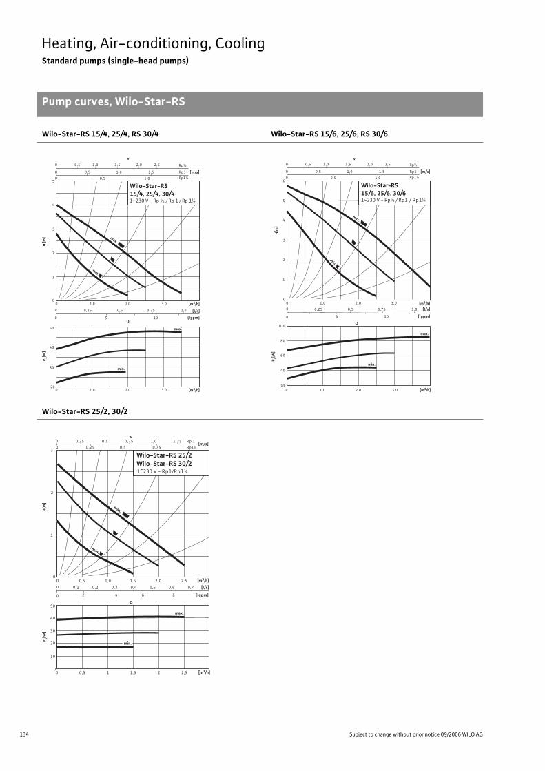
134 Subject to change without prior notice 09/2006 WILO AG
Heating, Air-conditioning, CoolingStandard pumps (single-head pumps)
Pump curves, Wilo-Star-RS
Wilo-Star-RS 15/4, 25/4, RS 30/4 Wilo-Star-RS 15/6, 25/6, RS 30/6
Wilo-Star-RS 25/2, 30/2
H [m
]
0,5
1,0 0
0
0
0
1
2
3
4
5
0 1,0 2,0 3,0
0
0 5 10
0,75
1,0
1,0
1,5
Rp½
0,5
0,25 0,5 1,0
min.
1,5 0,5 2,0 2,5
[m/s] Rp1
Rp1¼
20
50
40
30
P 1[W]
[l/s]
[lgpm]
[m3/h]
0 1,0 2,0 3,0 [m3/h]
v
Q
max.
min.
max.
Wilo-Star-RS15/4, 25/4, 30/41~230 V - Rp ½ / Rp 1 / Rp 1¼
Q
00
0
0
[l/s]
[lgpm]
020
0,75
1,0
1
2
5
6
105
100
60
80
min.
1,0 2,0 3,0
0,25 0,5 1,0
2,0 3,0
4
3
max.
40
max.
Wilo-Star-RS15/6, 25/6, 30/61~230 V - Rp½ / Rp1 / Rp1¼
[m3/h]
[m3/h]
P 1[W]
0,5
1,00
0
0
1,0
1,0
1,5
Rp½
0,5
1,50,5 2,0 2,5
[m/s]Rp1
Rp1¼
v
min.
H[m
]
Q
0,50
00
0
0
0,5
[l/s]
[lgpm]
00
0,5
0,5
[m/s]
1
2
30,25
v
0
1,0
0,75
1,25
84
50
40
30
20
10
Rp 1
Rp1¼
max.
0,25
0,5
0,75
min.
max.
1,0 1,5 2,0 2,5
0,20,1 0,3
2
0,4
6
0,6 0,7
1 1,5 2 2,5
Wilo-Star-RS 25/2Wilo-Star-RS 30/21~230 V - Rp1/Rp1¼
[m3/h]
P 1[W]
H[m
]
[m3/h]
min.
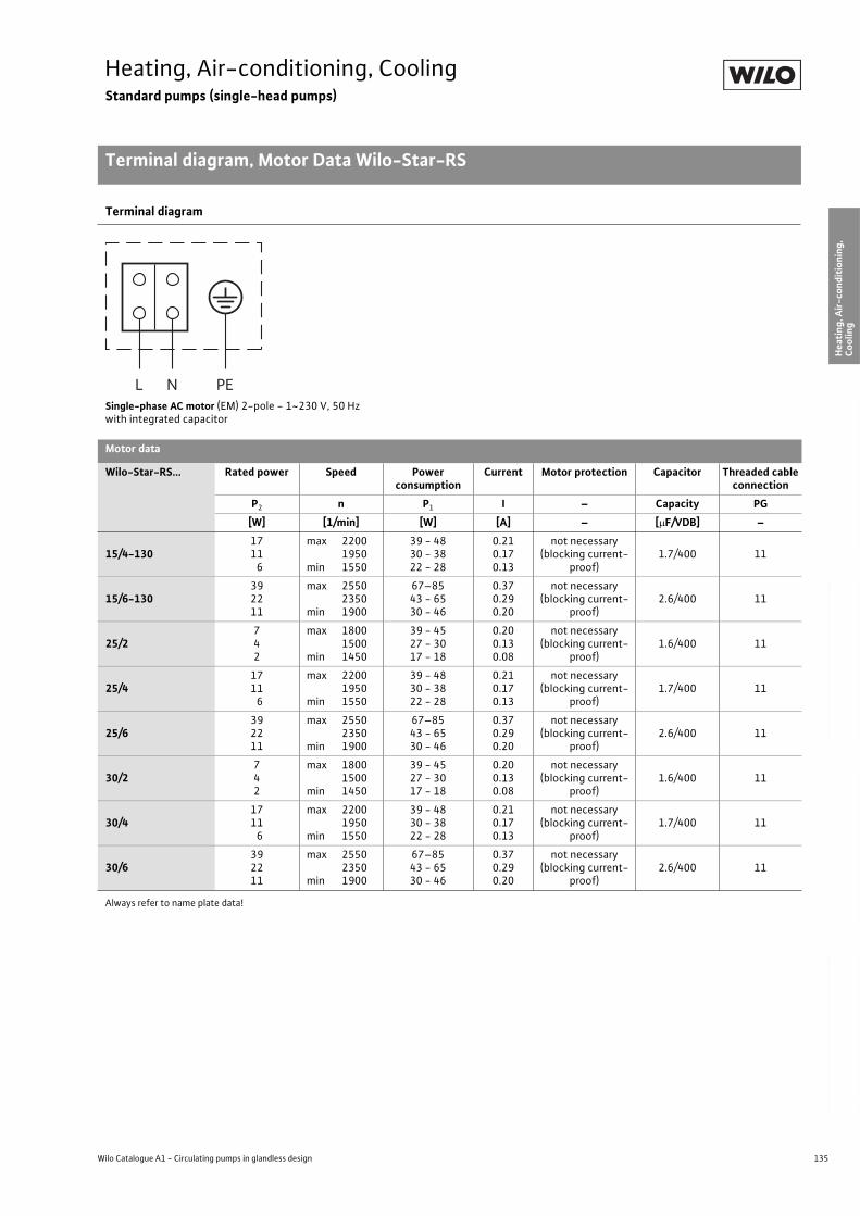
135
Heating, Air-conditioning, CoolingStandard pumps (single-head pumps)
Terminal diagram, Motor Data Wilo-Star-RS
Wilo Catalogue A1 - Circulating pumps in glandless design
Hea
tin
g, A
ir-c
on
dit
ion
ing
, C
oo
ling
Po
tab
le w
ater
cir
cula
tio
nSo
lar
ther
mal
Serv
ice/
Acc
esso
ries
, Sys
tem
sSw
itch
gea
rs a
nd
Co
ntr
ol
Dev
ices
P
um
p M
anag
emen
t S y
stem
s
Terminal diagram
Single-phase AC motor (EM) 2-pole - 1~230 V, 50 Hzwith integrated capacitor
Motor data
Wilo-Star-RS... Rated power Speed Power consumption
Current Motor protection Capacitor Threaded cable connection
P2 n P1 I – Capacity PG
[W] [1/min] [W] [A] – [ F/VDB] –
15/4-1301711
6
max 22001950
min 1550
39 - 4830 - 3822 - 28
0.210.170.13
not necessary (blocking current-
proof)1.7/400 11
15/6-130392211
max 25502350
min 1900
67–8543 - 6530 - 46
0.370.290.20
not necessary (blocking current-
proof)2.6/400 11
25/2742
max 18001500
min 1450
39 - 4527 - 3017 - 18
0.200.130.08
not necessary (blocking current-
proof)1.6/400 11
25/41711
6
max 22001950
min 1550
39 - 4830 - 3822 - 28
0.210.170.13
not necessary (blocking current-
proof)1.7/400 11
25/6392211
max 25502350
min 1900
67–8543 - 6530 - 46
0.370.290.20
not necessary (blocking current-
proof)2.6/400 11
30/2742
max 18001500
min 1450
39 - 4527 - 3017 - 18
0.200.130.08
not necessary (blocking current-
proof)1.6/400 11
30/41711
6
max 22001950
min 1550
39 - 4830 - 3822 - 28
0.210.170.13
not necessary (blocking current-
proof)1.7/400 11
30/6392211
max 25502350
min 1900
67–8543 - 6530 - 46
0.370.290.20
not necessary (blocking current-
proof)2.6/400 11
Always refer to name plate data!
L N PE
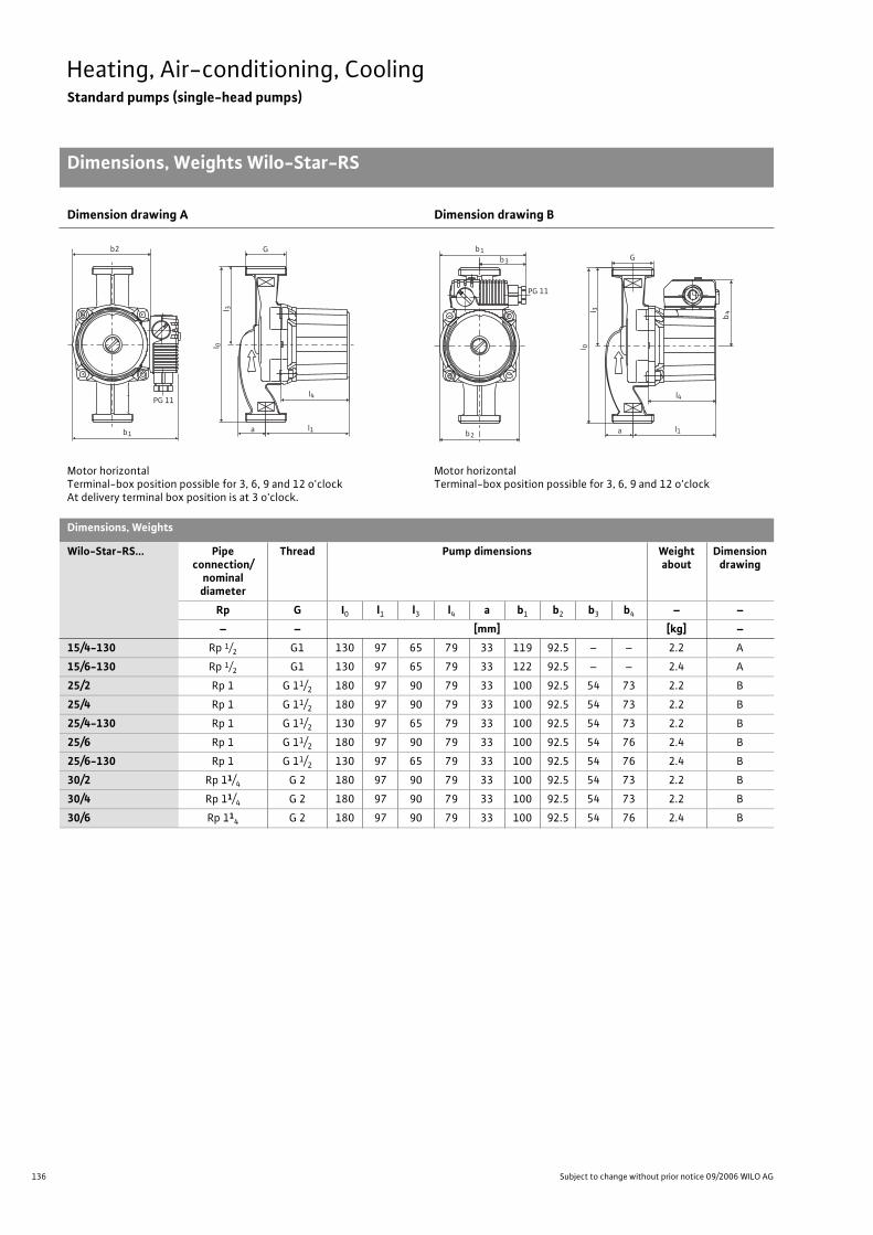
136 Subject to change without prior notice 09/2006 WILO AG
Heating, Air-conditioning, CoolingStandard pumps (single-head pumps)
Dimensions, Weights Wilo-Star-RS
Dimension drawing A Dimension drawing B
Motor horizontalTerminal-box position possible for 3, 6, 9 and 12 o'clockAt delivery terminal box position is at 3 o'clock.
Motor horizontalTerminal-box position possible for 3, 6, 9 and 12 o'clock
Dimensions, Weights
Wilo-Star-RS... Pipe connection/
nominal diameter
Thread Pump dimensions Weight about
Dimension drawing
Rp G I0 l1 l3 l4 a b1 b2 b3 b4 – –
– – [mm] [kg] –
15/4-130 Rp 1/2 G1 130 97 65 79 33 119 92.5 – – 2.2 A
15/6-130 Rp 1/2 G1 130 97 65 79 33 122 92.5 – – 2.4 A
25/2 Rp 1 G 11/2 180 97 90 79 33 100 92.5 54 73 2.2 B
25/4 Rp 1 G 11/2 180 97 90 79 33 100 92.5 54 73 2.2 B
25/4-130 Rp 1 G 11/2 130 97 65 79 33 100 92.5 54 73 2.2 B
25/6 Rp 1 G 11/2 180 97 90 79 33 100 92.5 54 76 2.4 B
25/6-130 Rp 1 G 11/2 130 97 65 79 33 100 92.5 54 76 2.4 B
30/2 Rp 11/4 G 2 180 97 90 79 33 100 92.5 54 73 2.2 B
30/4 Rp 11/4 G 2 180 97 90 79 33 100 92.5 54 73 2.2 B
30/6 Rp 114 G 2 180 97 90 79 33 100 92.5 54 76 2.4 B
b
b2
1
l 0
l1
l4
l 3
G
a
PG 11
b2
b1
b4
l 0
l1
l4
l 3
G
PG 11
b3
a

137
Heating, Air-conditioning, CoolingStandard pumps (single-head pumps)
Wilo Catalogue A1 - Circulating pumps in glandless design
Hea
tin
g, A
ir-c
on
dit
ion
ing
, C
oo
ling
Po
tab
le w
ater
cir
cula
tio
nSo
lar
ther
mal
Serv
ice/
Acc
esso
ries
, Sys
tem
sSw
itch
gea
rs a
nd
Co
ntr
ol
Dev
ices
P
um
p M
anag
emen
t S y
stem
s
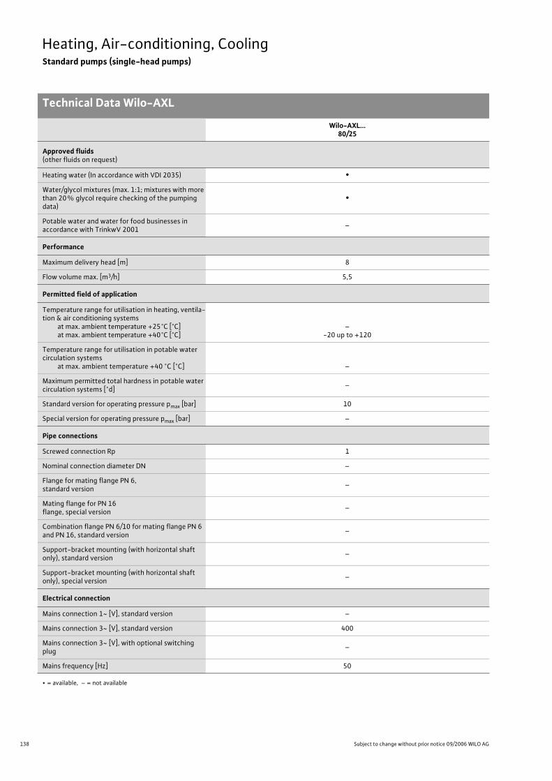
138 Subject to change without prior notice 09/2006 WILO AG
Heating, Air-conditioning, CoolingStandard pumps (single-head pumps)
Technical Data Wilo-AXL
Wilo-AXL…80/25
Approved fluids(other fluids on request)
Heating water (In accordance with VDI 2035) •
Water/glycol mixtures (max. 1:1; mixtures with more than 20% glycol require checking of the pumping data)
•
Potable water and water for food businesses in accordance with TrinkwV 2001
–
Performance
Maximum delivery head [m] 8
Flow volume max. [m3/h] 5,5
Permitted field of application
Temperature range for utilisation in heating, ventila-tion & air conditioning systems
at max. ambient temperature +25°C [°C]at max. ambient temperature +40°C [°C]
–-20 up to +120
Temperature range for utilisation in potable water circulation systems
at max. ambient temperature +40 °C [°C] –
Maximum permitted total hardness in potable water circulation systems [°d]
–
Standard version for operating pressure pmax [bar] 10
Special version for operating pressure pmax [bar] –
Pipe connections
Screwed connection Rp 1
Nominal connection diameter DN –
Flange for mating flange PN 6, standard version
–
Mating flange for PN 16 flange, special version
–
Combination flange PN 6/10 for mating flange PN 6 and PN 16, standard version
–
Support-bracket mounting (with horizontal shaft only), standard version
–
Support-bracket mounting (with horizontal shaft only), special version
–
Electrical connection
Mains connection 1~ [V], standard version –
Mains connection 3~ [V], standard version 400
Mains connection 3~ [V], with optional switching plug
–
Mains frequency [Hz] 50
• = available, – = not available

139
Heating, Air-conditioning, CoolingStandard pumps (single-head pumps)
Technical Data Wilo-AXL
Wilo Catalogue A1 - Circulating pumps in glandless design
Hea
tin
g, A
ir-c
on
dit
ion
ing
, C
oo
ling
Po
tab
le w
ater
cir
cula
tio
nSo
lar
ther
mal
Serv
ice/
Acc
esso
ries
, Sys
tem
sSw
itch
gea
rs a
nd
Co
ntr
ol
Dev
ices
P
um
p M
anag
emen
t S y
stem
s
Motor/electronics
Electromagnetic compatibility –
Emitted interference –
Immunity to interference –
Power electronics –
Protection class IP 42
Insulation class F
Materials
Pump housing Grey cast iron (EN-GJL-200)
Impeller Plastic (PPE, trade name Noryl)
Shaft Stainless steel (X46 Cr13)
Bearing Metal-impregnated carbon
Minimum suction head at suction branch [m]for the prevention of cavitation at water delivery temperature
50 °C 0,5
95 °C 3
110 °C 10
130 °C –
Wilo-AXL…80/25
• = available, – = not available
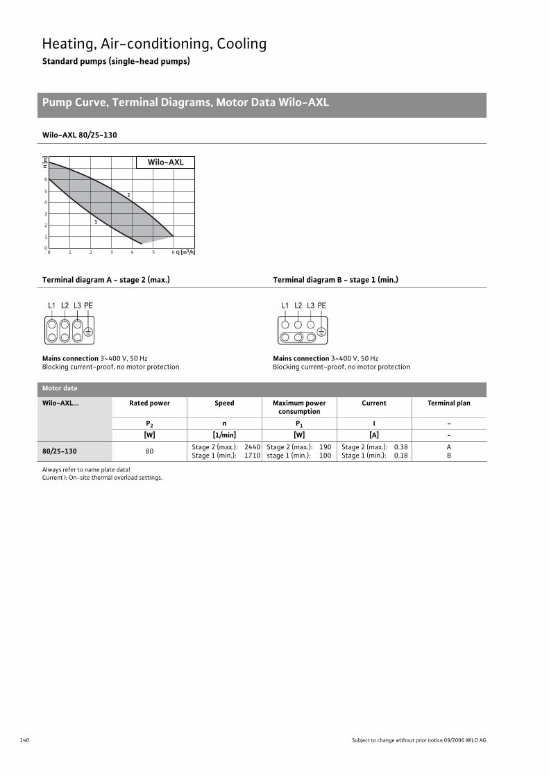
140 Subject to change without prior notice 09/2006 WILO AG
Heating, Air-conditioning, CoolingStandard pumps (single-head pumps)
Pump Curve, Terminal Diagrams, Motor Data Wilo-AXL
Wilo-AXL 80/25-130
Terminal diagram A - stage 2 (max.) Terminal diagram B - stage 1 (min.)
Mains connection 3~400 V, 50 HzBlocking current-proof, no motor protection
Mains connection 3~400 V, 50 HzBlocking current-proof, no motor protection
Motor data
Wilo-AXL... Rated power Speed Maximum power consumption
Current Terminal plan
P2 n P1 I -
[W] [1/min] [W] [A] -
80/25-130 80Stage 2 (max.): 2440Stage 1 (min.): 1710
Stage 2 (max.): 190stage 1 (min.): 100
Stage 2 (max.): 0.38Stage 1 (min.): 0.18
AB
Always refer to name plate data!Current I: On-site thermal overload settings.
6
5
4
3
1
2
00 1 3 42 65 Q [m3/h]
H [m
]
Wilo-AXL
2
1
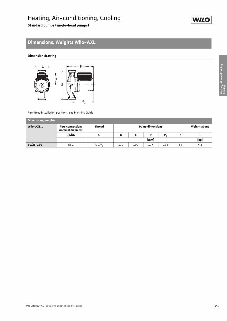
141
Heating, Air-conditioning, CoolingStandard pumps (single-head pumps)
Dimensions, Weights Wilo-AXL
Wilo Catalogue A1 - Circulating pumps in glandless design
Hea
tin
g, A
ir-c
on
dit
ion
ing
, C
oo
ling
Po
tab
le w
ater
cir
cula
tio
nSo
lar
ther
mal
Serv
ice/
Acc
esso
ries
, Sys
tem
sSw
itch
gea
rs a
nd
Co
ntr
ol
Dev
ices
P
um
p M
anag
emen
t S y
stem
s
Dimension drawing
Permitted installation positions, see Planning Guide
Dimensions, Weights
Wilo-AXL... Pipe connection/nominal diameter
Thread Pump dimensions Weight about
Rp/DN G B L P P1 h –
- – [mm] [kg]
80/25-130 Rp 1 G 11/2 130 100 177 138 84 4.2
L P
P1
Bh

142 Subject to change without prior notice 09/2006 WILO AG
Heating, Air-conditioning, CoolingStandard pumps (single-head pumps)
Technical Data Wilo-TOP-RL
Wilo-TOP-RL...
25/7,5 30/4 30/6,5 30/7,5
Approved fluids(other fluids on request)
Heating water (In accordance with VDI 2035) • • • •
Water/glycol mixtures (max. 1:1; mixtures with more than 20% glycol require checking of the pumping data)
• • • •
Potable water and water for food businesses in accordance with TrinkwV 2001
– – – –
Performance
Maximum delivery head [m] 7.5 4.0 7.0 7.5
Flow volume max. [m3/h] 6.5 9.0 10.0 6.5
Permitted field of application
Temperature range for utilisation in heating, ventila-tion and A/C systems
at max. ambient temperature +25°C [°C]at max. ambient temperature +40°C [°C]
–-20 up to +130
Temperature range for utilisation in potable water circulation systems
at max. ambient temperature +40 °C [°C] – – – –
Maximum permitted total hardness in potable water circulation systems [°d]
– – – –
Standard version for operating pressure pmax [bar] 10 10 10 10
Special version for operating pressure pmax [bar] – – – –
Pipe connections
Screwed connection Rp 1 11/4 11/4 11/4
Nominal connection diameter DN – – – –
Flange for mating flange PN 6, standard version
– – – –
Mating flange for PN 16 flange, special version
– – – –
Combination flange PN 6/10 for mating flange PN 6 and PN 16, standard version
– – – –
Support-bracket mounting (with horizontal shaft only), standard version
– – – –
Support-bracket mounting (with horizontal shaft only), special version
– – – –
Electrical connection
Mains connection 1~ [V], standard version 230 230 230 230
Mains connection 3~ [V], standard version – – – –
Mains connection 3~ [V], with optional switching plug
– – – –
Mains frequency [Hz] 50 50 50 50
• = available, – = not available

143
Heating, Air-conditioning, CoolingStandard pumps (single-head pumps)
Technical Data Wilo-TOP-RL
Wilo Catalogue A1 - Circulating pumps in glandless design
Hea
tin
g, A
ir-c
on
dit
ion
ing
, C
oo
ling
Po
tab
le w
ater
cir
cula
tio
nSo
lar
ther
mal
Serv
ice/
Acc
esso
ries
, Sys
tem
sSw
itch
gea
rs a
nd
Co
ntr
ol
Dev
ices
P
um
p M
anag
emen
t S y
stem
s
Motor/electronics
Electromagnetic compatibility – – – –
Emitted interference EN 61000-6-3
Immunity to interference EN 61000-6-2
Power electronics – – – –
Protection class IP 44 IP 44 IP 44 IP 44
Insulation class F F F F
Materials
Pump housing Grey cast iron (EN-GJL-200)
Impeller Plastic (PPE, trade name Noryl)
Shaft Stainless steel (X46 Cr13)
Bearing Metal-impregnated carbon
Minimum suction head at suction branch [m]for the prevention of cavitation at water delivery temperature
50 °C 0.5 0.5 0.5 0.5
95 °C 5.0 5.0 5.0 5.0
110 °C 11.0 11.0 11.0 11.0
130 °C 24.0 24.0 24.0 24.0
Wilo-TOP-RL...
25/7,5 30/4 30/6,5 30/7,5
• = available, – = not available
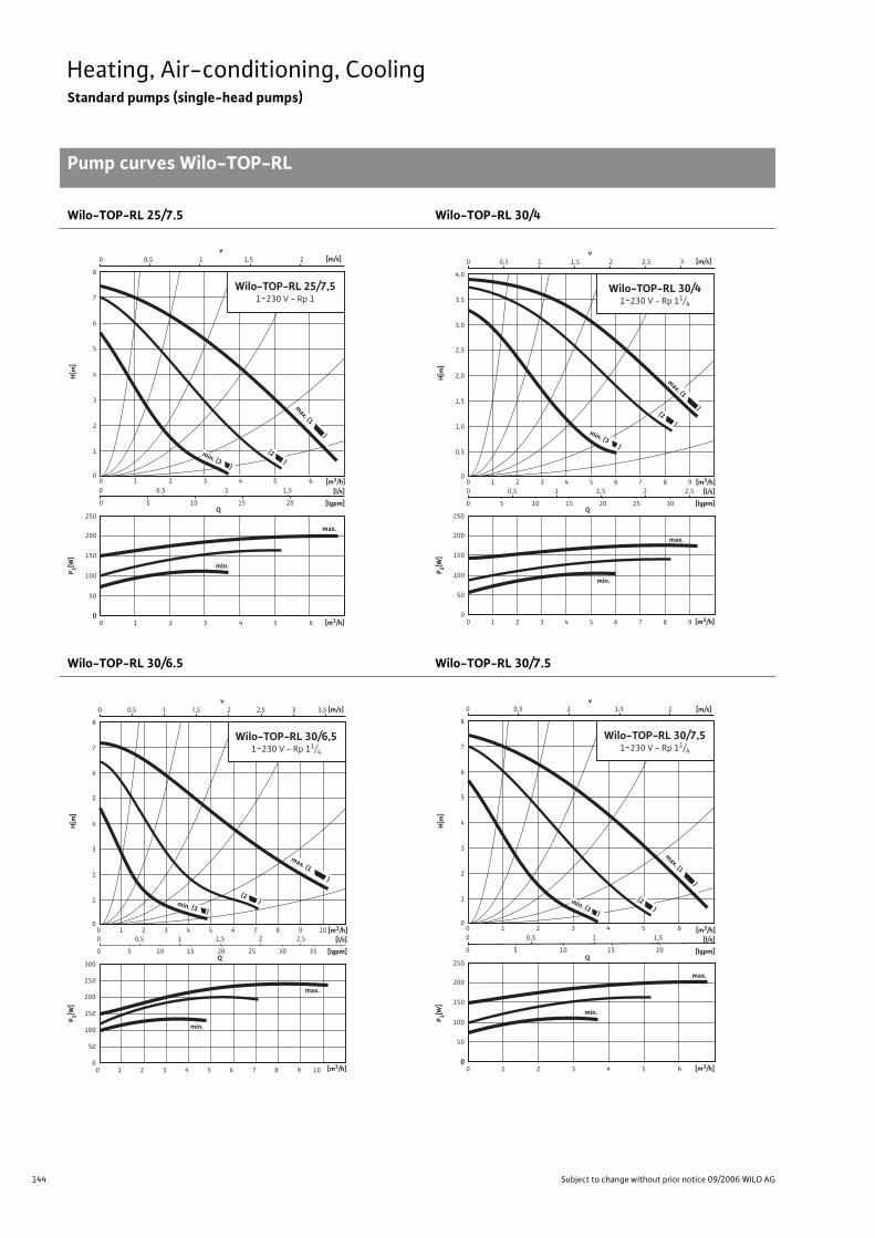
144 Subject to change without prior notice 09/2006 WILO AG
Heating, Air-conditioning, CoolingStandard pumps (single-head pumps)
Pump curves Wilo-TOP-RL
Wilo-TOP-RL 25/7.5 Wilo-TOP-RL 30/4
Wilo-TOP-RL 30/6.5 Wilo-TOP-RL 30/7.5
[l/s]
[lgpm]
[m/s]
[m3/h]
[m3/h]
P 1[W]
H[m
]
Q
8
7
6
5
4
3
2
1
0
0
v
0 1 2 3 4 5 6 0 0,5 1 1,5
0 5 10 15 20
0 1 2 3 4 5 6
0,5 0 1 1,5 2
250
200
150
100
50
0
max. (1 )
min. (3 )
(2 )
Wilo-TOP-RL 25/7,51~230 V - Rp 1
min.
max.
[l/s]
[lgpm]
[m/s]
[m3/h]
[m3/h]
P 1[W]
H[m
]
Q
v
250
4,0
3,5
3,0
2,5
2,0
1,5
1,0
0,5
00 1 2 3 4 5 6 7 8 9
0 1 2 3 4 5 6 7 8 9
0 0,5 1 1,5 2 2,5
0 5 1510 20 25 30
200
150
100
50
0
0 0,5 1 1,5 2 2,5 3
max. (1 )
min. (3 )
(2 )
Wilo-TOP-RL 30/41~230 V - Rp 11/4
min.
max.
[l/s]
[lgpm]
[m/s]
[m3/h]
[m3/h]
P 1[W]
H[m
]
Q
v
0 0,5 1 1,5 2 2,5
0 0,5 1 1,5 2 2,5
0 5 10 15 20 25 30
0 1 2 3 4 5 6 7 8 9 10
0 1 2 3 4 5 6 7 8 9 10
35
300
8
7
6
5
4
3
2
1
0
250
200
150
100
50
0
3 3,5
max. (1 )
min. (3 )
(2 )
Wilo-TOP-RL 30/6,51~230 V - Rp 11/4
min.
max.
[l/s]
[lgpm]
[m/s]
[m3/h]
[m3/h]
P 1[W]
H[m
]
Q
v
8
7
6
5
4
3
2
1
0
0
0 1 2 3 4 5 60 0,5 1 1,5
0 5 10 15 20
0 1 2 3 4 5 6
0,5 0 1 1,5 2
250
200
150
100
50
0
max. (1 )
min. (3 )
(2 )
Wilo-TOP-RL 30/7,51~230 V - Rp 11/4
min.
max.
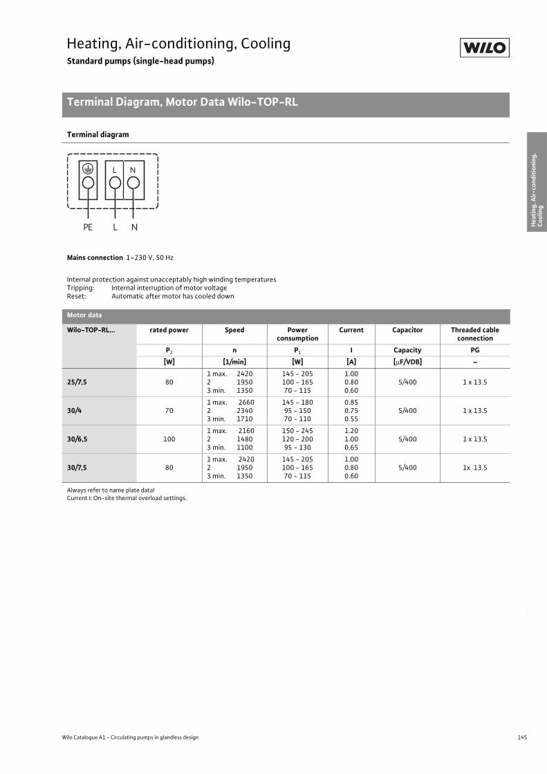
145
Heating, Air-conditioning, CoolingStandard pumps (single-head pumps)
Terminal Diagram, Motor Data Wilo-TOP-RL
Wilo Catalogue A1 - Circulating pumps in glandless design
Hea
tin
g, A
ir-c
on
dit
ion
ing
, C
oo
ling
Po
tab
le w
ater
cir
cula
tio
nSo
lar
ther
mal
Serv
ice/
Acc
esso
ries
, Sys
tem
sSw
itch
gea
rs a
nd
Co
ntr
ol
Dev
ices
P
um
p M
anag
emen
t S y
stem
s
Terminal diagram
Mains connection 1~230 V, 50 Hz
Internal protection against unacceptably high winding temperaturesTripping: Internal interruption of motor voltageReset: Automatic after motor has cooled down
Motor data
Wilo-TOP-RL... rated power Speed Power consumption
Current Capacitor Threaded cable connection
P2 n P1 I Capacity PG
[W] [1/min] [W] [A] [ F/VDB] –
25/7,5 801 max. 2420 2 19503 min. 1350
145 - 205100 - 16570 - 115
1.000.800.60
5/400 1 x 13.5
30/4 701 max. 2660 2 23403 min. 1710
145 - 18095 - 15070 - 110
0.850.750.55
5/400 1 x 13.5
30/6,5 1001 max. 2160 2 14803 min. 1100
150 - 245120 - 20095 - 130
1.201.000.65
5/400 1 x 13.5
30/7,5 801 max. 2420 2 19503 min. 1350
145 - 205100 - 16570 - 115
1.000.800.60
5/400 1x 13.5
Always refer to name plate data!Current I: On-site thermal overload settings.
L NPE
NL
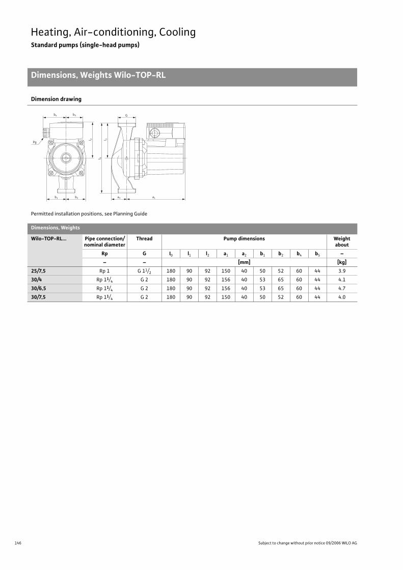
146 Subject to change without prior notice 09/2006 WILO AG
Heating, Air-conditioning, CoolingStandard pumps (single-head pumps)
Dimensions, Weights Wilo-TOP-RL
Dimension drawing
Permitted installation positions, see Planning Guide
Dimensions, Weights
Wilo-TOP-RL... Pipe connection/nominal diameter
Thread Pump dimensions Weight about
Rp G I0 l1 l2 a1 a2 b1 b2 b4 b5 –
– – [mm] [kg]
25/7,5 Rp 1 G 11/2 180 90 92 150 40 50 52 60 44 3.9
30/4 Rp 11/4 G 2 180 90 92 156 40 53 65 60 44 4.1
30/6,5 Rp 11/4 G 2 180 90 92 156 40 53 65 60 44 4.7
30/7,5 Rp 11/4 G 2 180 90 92 150 40 50 52 60 44 4.0
b1 b2 a3 a1
b5b4 G
Pg
l 2
l 1
l 0

147
Heating, Air-conditioning, CoolingStandard pumps (single-head pumps)
Wilo Catalogue A1 - Circulating pumps in glandless design
Hea
tin
g, A
ir-c
on
dit
ion
ing
, C
oo
ling
Po
tab
le w
ater
cir
cula
tio
nSo
lar
ther
mal
Serv
ice/
Acc
esso
ries
, Sys
tem
sSw
itch
gea
rs a
nd
Co
ntr
ol
Dev
ices
P
um
p M
anag
emen
t S y
stem
s
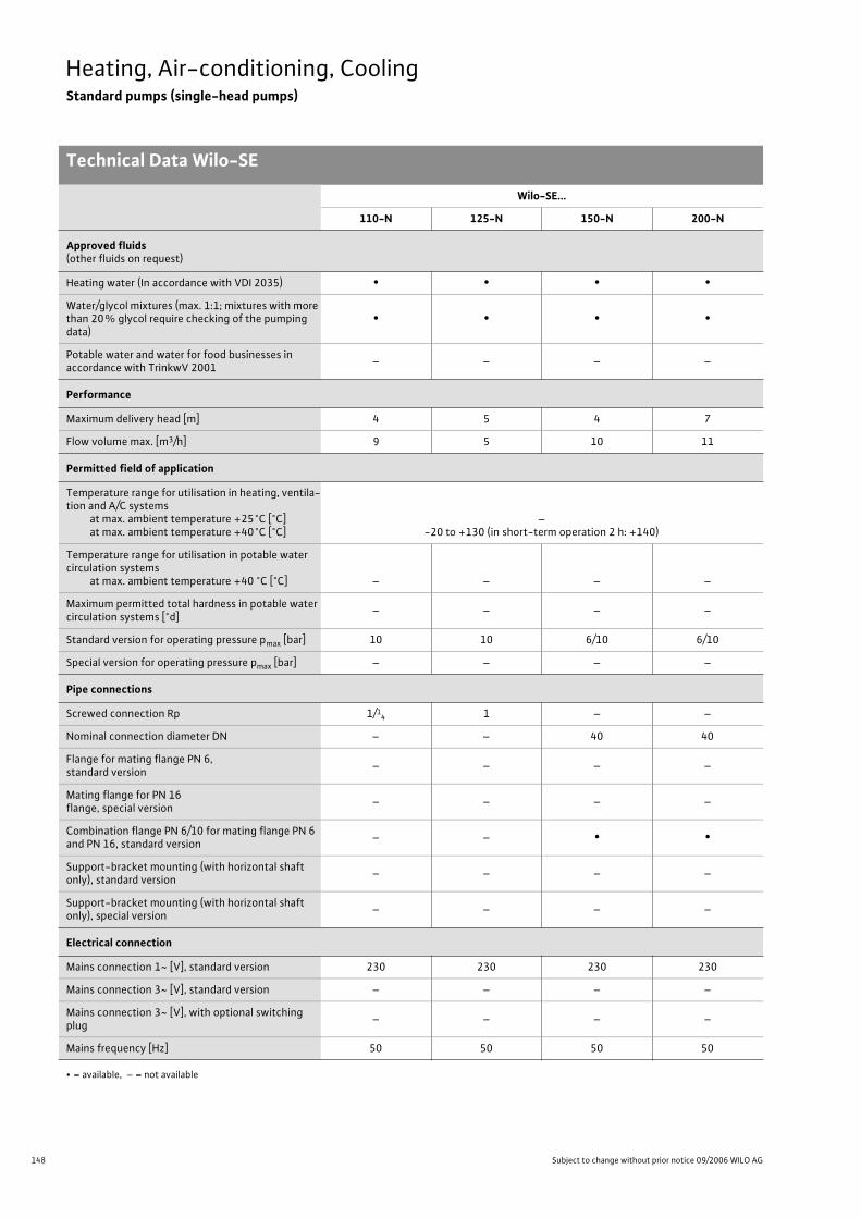
148 Subject to change without prior notice 09/2006 WILO AG
Heating, Air-conditioning, CoolingStandard pumps (single-head pumps)
Technical Data Wilo-SE
Wilo-SE...
110-N 125-N 150-N 200-N
Approved fluids(other fluids on request)
Heating water (In accordance with VDI 2035) • • • •
Water/glycol mixtures (max. 1:1; mixtures with more than 20% glycol require checking of the pumping data)
• • • •
Potable water and water for food businesses in accordance with TrinkwV 2001
– – – –
Performance
Maximum delivery head [m] 4 5 4 7
Flow volume max. [m3/h] 9 5 10 11
Permitted field of application
Temperature range for utilisation in heating, ventila-tion and A/C systems
at max. ambient temperature +25°C [°C]at max. ambient temperature +40°C [°C]
–-20 to +130 (in short-term operation 2 h: +140)
Temperature range for utilisation in potable water circulation systems
at max. ambient temperature +40 °C [°C] – – – –
Maximum permitted total hardness in potable water circulation systems [°d]
– – – –
Standard version for operating pressure pmax [bar] 10 10 6/10 6/10
Special version for operating pressure pmax [bar] – – – –
Pipe connections
Screwed connection Rp 1/14 1 – –
Nominal connection diameter DN – – 40 40
Flange for mating flange PN 6, standard version
– – – –
Mating flange for PN 16 flange, special version
– – – –
Combination flange PN 6/10 for mating flange PN 6 and PN 16, standard version
– – • •
Support-bracket mounting (with horizontal shaft only), standard version
– – – –
Support-bracket mounting (with horizontal shaft only), special version
– – – –
Electrical connection
Mains connection 1~ [V], standard version 230 230 230 230
Mains connection 3~ [V], standard version – – – –
Mains connection 3~ [V], with optional switching plug
– – – –
Mains frequency [Hz] 50 50 50 50
• = available, – = not available

149
Heating, Air-conditioning, CoolingStandard pumps (single-head pumps)
Technical Data Wilo-SE
Wilo Catalogue A1 - Circulating pumps in glandless design
Hea
tin
g, A
ir-c
on
dit
ion
ing
, C
oo
ling
Po
tab
le w
ater
cir
cula
tio
nSo
lar
ther
mal
Serv
ice/
Acc
esso
ries
, Sys
tem
sSw
itch
gea
rs a
nd
Co
ntr
ol
Dev
ices
P
um
p M
anag
emen
t S y
stem
s
Motor/electronics
Electromagnetic compatibility – – – –
Emitted interference EN 61000-6-3
Immunity to interference EN 61000-6-2
Power electronics – – – –
Protection class IP 44 IP 44 IP 44 IP 44
Insulation class F F F F
Materials
Pump housing Grey cast iron (EN-GJL-200) Grey cast iron (EN-GJL-250)
Impeller Plastic (PPE, trade name: Noryl)
Shaft Stainless steel (X40 Cr13)
Bearing Metal-impregnated carbon
Minimum suction head at suction branch [m]for the prevention of cavitation at water delivery temperature
50 °C 0.5 0.5 0.5 0.5
95 °C 5 5 5 5
110 °C 11 11 11 11
130 °C 24 24 24 24
Wilo-SE...
110-N 125-N 150-N 200-N
• = available, – = not available
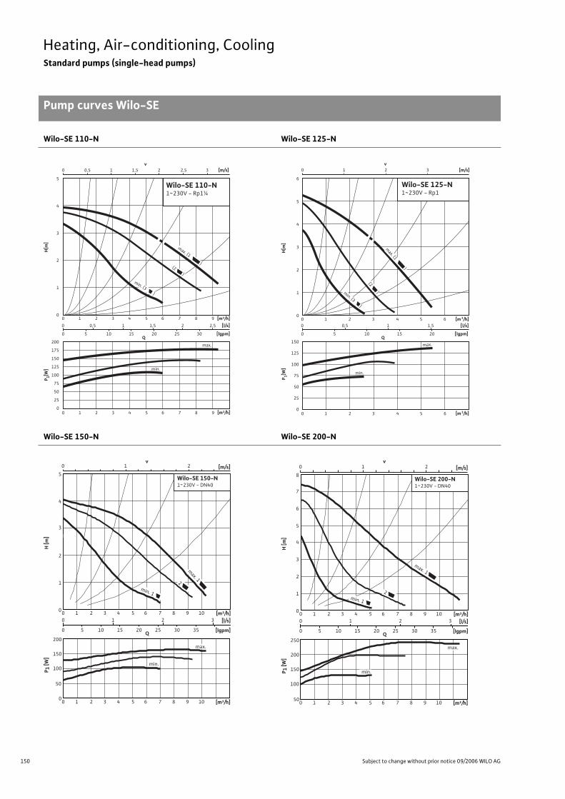
150 Subject to change without prior notice 09/2006 WILO AG
Heating, Air-conditioning, CoolingStandard pumps (single-head pumps)
Pump curves Wilo-SE
Wilo-SE 110-N Wilo-SE 125-N
Wilo-SE 150-N Wilo-SE 200-N
P 1[W]
H[m
]
0 0,5 1 1,5 2 2,5
0 5 10 15 20 25 30
0 1 2 3 4 5 6 7 8 9
0 1 2 3 4 5 6 7 8 9 [m³/h]
[m³/h]
Q[lgpm]
200
175
150
125
100
75
50
25
0
5
4
3
2
1
0
[l/s]
max. (1 )
min. (3 )
(2 )
0 0,5 1 1,5 2 2,5 3v
[m/s]
Wilo-SE 110-N1~230V - Rp1¼
min.
max.
0 1 2 3 4 5 6
0 1 2 3 4 5 6 [m 3/h]
Q
[m 3/h]
150
125
100
75
50
25
0
6
5
4
3
2
1
0
0 0,5 1 1,5
0 5 10 15 20 [lgpm]
[l/s]
min. (3 )
(2 )
min.
max.
0 1 2 3v
[m/s]
max. (1 )
P 1[W]
H[m
]
Wilo-SE 125-N1~230V - Rp1
H [m
]P 1
[W]
0 1 2
0
0
50
100
150
200
1
2
3
4
5
10 2 3
0 1 2 3 [l/s]
0 5 10 15 20 25 30 35 [Igpm]
4 5 6 7 8 9 10 [m³/h]
10 2 3 4 5 6 7 8 9 10 [m³/h]
v[m/s]
Wilo-SE 150-N1~230V - DN40
Q
max. 1
2
min. 1
min.
max.
H [m
]P 1
[W]
max. 1
2
0 1 2
0
50
100
150
200
250
1
2
3
4
5
6
7
8
10 2 3
0 1 2 3 [l/s]
0 5 10 15 20 25 30 35 [Igpm]
4 5 6 7 8 9 10 [m³/h]
10 2 3 4 5 6 7 8 9 10 [m³/h]
v[m/s]
min. 1
min.
max.
Wilo-SE 200-N1~230V - DN40
Q
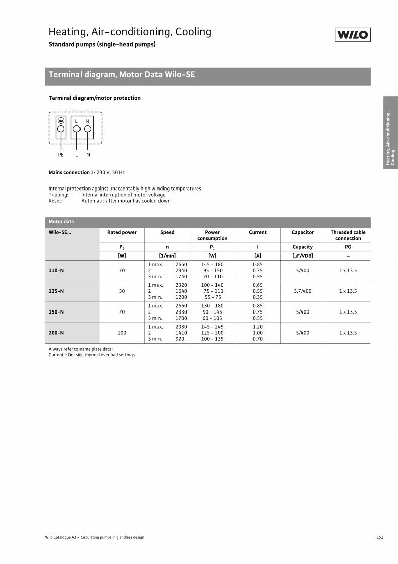
151
Heating, Air-conditioning, CoolingStandard pumps (single-head pumps)
Terminal diagram, Motor Data Wilo-SE
Wilo Catalogue A1 - Circulating pumps in glandless design
Hea
tin
g, A
ir-c
on
dit
ion
ing
, C
oo
ling
Po
tab
le w
ater
cir
cula
tio
nSo
lar
ther
mal
Serv
ice/
Acc
esso
ries
, Sys
tem
sSw
itch
gea
rs a
nd
Co
ntr
ol
Dev
ices
P
um
p M
anag
emen
t S y
stem
s
Terminal diagram/motor protection
Mains connection 1~230 V, 50 Hz
Internal protection against unacceptably high winding temperaturesTripping: Internal interruption of motor voltageReset: Automatic after motor has cooled down
Motor data
Wilo-SE... Rated power Speed Power consumption
Current Capacitor Threaded cable connection
P2 n P1 I Capacity PG
[W] [1/min] [W] [A] [ F/VDB] –
110-N 701 max. 2660 2 23403 min. 1740
145 - 180 95 - 150 70 - 110
0.850.750.55
5/400 1 x 13.5
125-N 501 max. 2320 2 16403 min. 1200
100 - 140 75 - 110 55 - 75
0.650.550.35
3,7/400 1 x 13.5
150-N 701 max. 2660 2 23303 min. 1700
130 - 18090 - 14560 - 105
0.850.750.55
5/400 1 x 13.5
200-N 1001 max. 2080 2 14103 min. 920
145 - 245125 - 200100 - 135
1.201.000.70
5/400 1 x 13.5
Always refer to name plate data!Current I: On-site thermal overload settings.
L NPE
NL
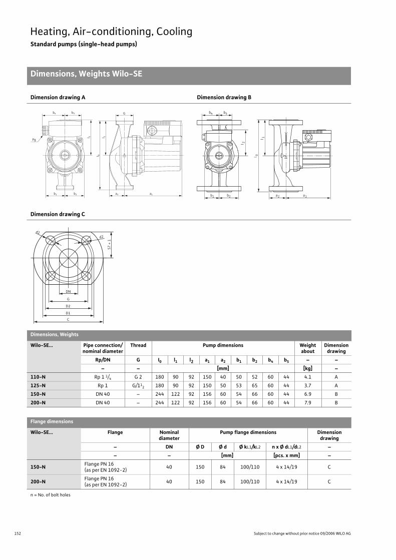
152 Subject to change without prior notice 09/2006 WILO AG
Heating, Air-conditioning, CoolingStandard pumps (single-head pumps)
Dimensions, Weights Wilo-SE
Dimension drawing A Dimension drawing B
Dimension drawing C
Dimensions, Weights
Wilo-SE... Pipe connection/nominal diameter
Thread Pump dimensions Weight about
Dimension drawing
Rp/DN G I0 l1 l2 a1 a2 b1 b2 b4 b5 – –
– – [mm] [kg] –
110-N Rp 1 1/4 G 2 180 90 92 150 40 50 52 60 44 4.1 A
125-N Rp 1 G/112 180 90 92 150 50 53 65 60 44 3.7 A
150-N DN 40 – 244 122 92 156 60 54 66 60 44 6.9 B
200-N DN 40 – 244 122 92 156 60 54 66 60 44 7.9 B
Flange dimensions
Wilo-SE... Flange Nominal diameter
Pump flange dimensions Dimension drawing
– DN Ø D Ø d Ø kL1/kL2 n x Ø dL1/dL2 –
– – [mm] [pcs. x mm] –
150-NFlange PN 16 (as per EN 1092-2)
40 150 84 100/110 4 x 14/19 C
200-NFlange PN 16 (as per EN 1092-2)
40 150 84 100/110 4 x 14/19 C
n = No. of bolt holes
b1 b2 a3 a1
b5b4 G
Pg
l 2
l 1
l 0
l 2
l 1
l 0
b4 b5
b1 b2 a2 a1
57
+ 1
G
D1
d1 d2
D2
C
DN

153
Heating, Air-conditioning, CoolingStandard pumps (single-head pumps)
Wilo Catalogue A1 - Circulating pumps in glandless design
Hea
tin
g, A
ir-c
on
dit
ion
ing
, C
oo
ling
Po
tab
le w
ater
cir
cula
tio
nSo
lar
ther
mal
Serv
ice/
Acc
esso
ries
, Sys
tem
sSw
itch
gea
rs a
nd
Co
ntr
ol
Dev
ices
P
um
p M
anag
emen
t S y
stem
s
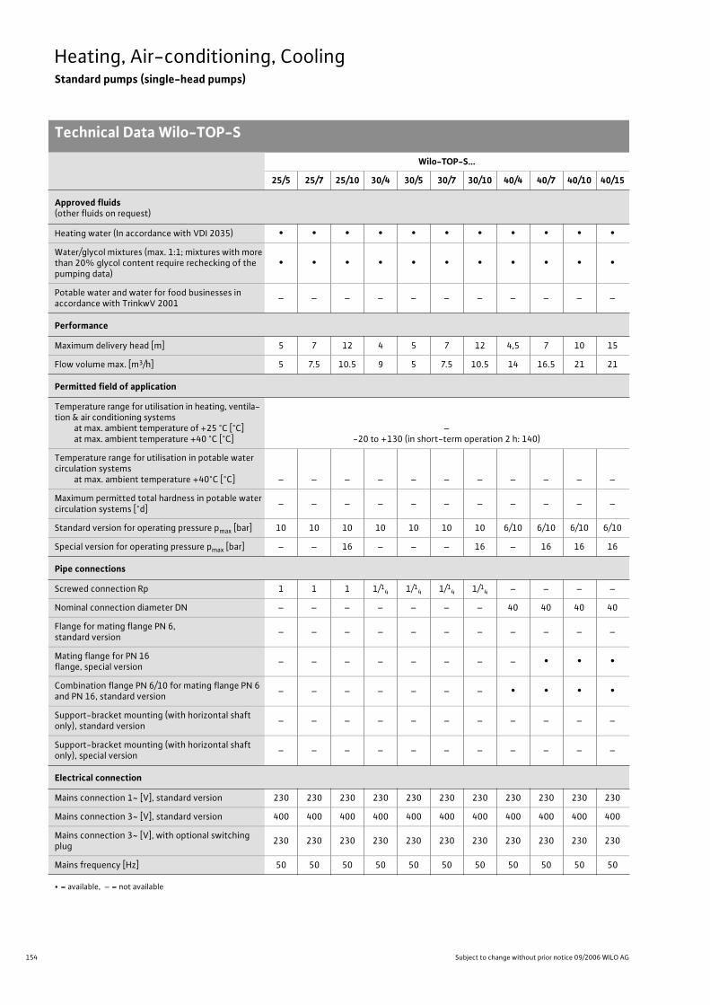
154 Subject to change without prior notice 09/2006 WILO AG
Heating, Air-conditioning, CoolingStandard pumps (single-head pumps)
Technical Data Wilo-TOP-S
Wilo-TOP-S...
25/5 25/7 25/10 30/4 30/5 30/7 30/10 40/4 40/7 40/10 40/15
Approved fluids(other fluids on request)
Heating water (In accordance with VDI 2035) • • • • • • • • • • •
Water/glycol mixtures (max. 1:1; mixtures with more than 20% glycol content require rechecking of the pumping data)
• • • • • • • • • • •
Potable water and water for food businesses in accordance with TrinkwV 2001
– – – – – – – – – – –
Performance
Maximum delivery head [m] 5 7 12 4 5 7 12 4,5 7 10 15
Flow volume max. [m3/h] 5 7.5 10.5 9 5 7.5 10.5 14 16.5 21 21
Permitted field of application
Temperature range for utilisation in heating, ventila-tion & air conditioning systems
at max. ambient temperature of +25 °C [°C]at max. ambient temperature +40 °C [°C]
–-20 to +130 (in short-term operation 2 h: 140)
Temperature range for utilisation in potable water circulation systems
at max. ambient temperature +40°C [°C] – – – – – – – – – – –
Maximum permitted total hardness in potable water circulation systems [°d]
– – – – – – – – – – –
Standard version for operating pressure pmax [bar] 10 10 10 10 10 10 10 6/10 6/10 6/10 6/10
Special version for operating pressure pmax [bar] – – 16 – – – 16 – 16 16 16
Pipe connections
Screwed connection Rp 1 1 1 1/14 1/1
4 1/14 1/1
4 – – – –
Nominal connection diameter DN – – – – – – – 40 40 40 40
Flange for mating flange PN 6, standard version
– – – – – – – – – – –
Mating flange for PN 16 flange, special version
– – – – – – – – • • •
Combination flange PN 6/10 for mating flange PN 6 and PN 16, standard version
– – – – – – – • • • •
Support-bracket mounting (with horizontal shaft only), standard version
– – – – – – – – – – –
Support-bracket mounting (with horizontal shaft only), special version
– – – – – – – – – – –
Electrical connection
Mains connection 1~ [V], standard version 230 230 230 230 230 230 230 230 230 230 230
Mains connection 3~ [V], standard version 400 400 400 400 400 400 400 400 400 400 400
Mains connection 3~ [V], with optional switching plug
230 230 230 230 230 230 230 230 230 230 230
Mains frequency [Hz] 50 50 50 50 50 50 50 50 50 50 50
• = available, – = not available
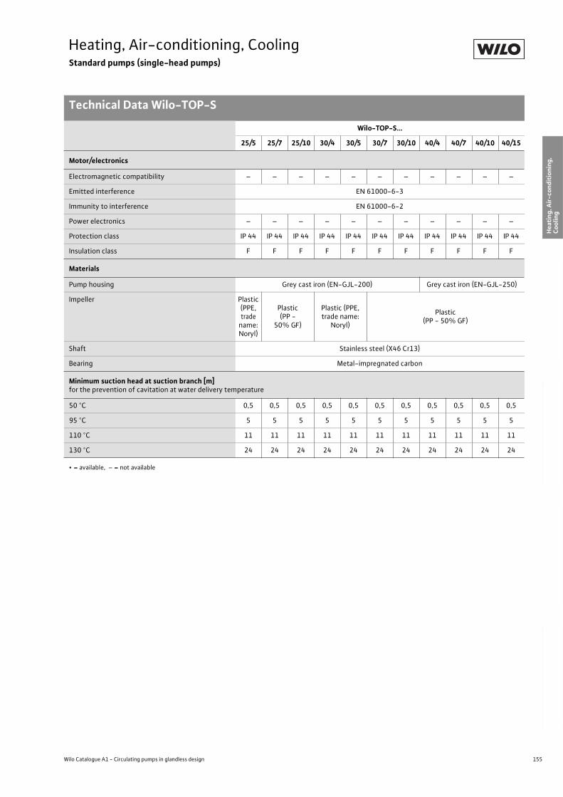
155
Heating, Air-conditioning, CoolingStandard pumps (single-head pumps)
Technical Data Wilo-TOP-S
Wilo Catalogue A1 - Circulating pumps in glandless design
Hea
tin
g, A
ir-c
on
dit
ion
ing
, C
oo
ling
Po
tab
le w
ater
cir
cula
tio
nSo
lar
ther
mal
Serv
ice/
Acc
esso
ries
, Sys
tem
sSw
itch
gea
rs a
nd
Co
ntr
ol
Dev
ices
P
um
p M
anag
emen
t S y
stem
s
Motor/electronics
Electromagnetic compatibility – – – – – – – – – – –
Emitted interference EN 61000-6-3
Immunity to interference EN 61000-6-2
Power electronics – – – – – – – – – – –
Protection class IP 44 IP 44 IP 44 IP 44 IP 44 IP 44 IP 44 IP 44 IP 44 IP 44 IP 44
Insulation class F F F F F F F F F F F
Materials
Pump housing Grey cast iron (EN-GJL-200) Grey cast iron (EN-GJL-250)
Impeller Plastic(PPE, trade
name: Noryl)
Plastic(PP -
50% GF)
Plastic (PPE, trade name:
Noryl)
Plastic(PP - 50% GF)
Shaft Stainless steel (X46 Cr13)
Bearing Metal-impregnated carbon
Minimum suction head at suction branch [m]for the prevention of cavitation at water delivery temperature
50 °C 0,5 0,5 0,5 0,5 0,5 0,5 0,5 0,5 0,5 0,5 0,5
95 °C 5 5 5 5 5 5 5 5 5 5 5
110 °C 11 11 11 11 11 11 11 11 11 11 11
130 °C 24 24 24 24 24 24 24 24 24 24 24
Wilo-TOP-S...
25/5 25/7 25/10 30/4 30/5 30/7 30/10 40/4 40/7 40/10 40/15
• = available, – = not available
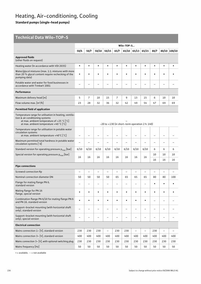
156 Subject to change without prior notice 09/2006 WILO AG
Heating, Air-conditioning, CoolingStandard pumps (single-head pumps)
Technical Data Wilo-TOP-S
Wilo-TOP-S...
50/4 50/7 50/10 50/15 65/7 65/10 65/13 65/15 80/7 80/10 100/10
Approved fluids(other fluids on request)
Heating water (In accordance with VDI 2035) • • • • • • • • • • •
Water/glycol mixtures (max. 1:1; mixtures with more than 20 % glycol content require rechecking of the pumping data)
• • • • • • • • • • •
Potable water and water for food businesses in accordance with TrinkwV 2001
– – – – – – – – – – –
Performance
Maximum delivery head [m] 5 7 10 15 7 9 13 15 6 10 10
Flow volume max. [m3/h] 23 28 32 36 32 42 49 54 47 69 69
Permitted field of application
Temperature range for utilisation in heating, ventila-tion & air conditioning systems
at max. ambient temperature of +25 °C [°C]at max. ambient temperature +40 °C [°C]
–-20 to +130 (in short-term operation 2 h: 140)
Temperature range for utilisation in potable water circulation systems
at max. ambient temperature +40°C [°C] – – – – – – – – – – –
Maximum permitted total hardness in potable water circulation systems [°d]
– – – – – – – – – – –
Standard version for operating pressure pmax [bar] 6/10 6/10 6/10 6/10 6/10 6/10 6/10 6/10 6 6 6
Special version for operating pressure pmax [bar]16 16 16 16 16 16 16 16
10 10 10
16 16 16
Pipe connections
Screwed connection Rp – – – – – – – – – – –
Nominal connection diameter DN 50 50 50 50 65 65 65 65 80 80 100
Flange for mating flange PN 6, standard version
– – – – – – – – • • •
Mating flange for PN 16 flange, special version
• • • • • • • • • • •
Combination flange PN 6/10 for mating flange PN 6 and PN 16, standard version
• • • • • • • • – – –
Support-bracket mounting (with horizontal shaft only), standard version
– – – – – – – – – – –
Support-bracket mounting (with horizontal shaft only), special version
– – – – – – – – – – –
Electrical connection
Mains connection 1~ [V], standard version 230 230 230 – 230 230 – – 230 – –
Mains connection 3~ [V], standard version 400 400 400 400 400 400 400 400 400 400 400
Mains connection 3~ [V], with optional switching plug 230 230 230 230 230 230 230 230 230 230 230
Mains frequency [Hz] 50 50 50 50 50 50 50 50 50 50 50
• = available, – = not available

157
Heating, Air-conditioning, CoolingStandard pumps (single-head pumps)
Technical Data Wilo-TOP-S
Wilo Catalogue A1 - Circulating pumps in glandless design
Hea
tin
g, A
ir-c
on
dit
ion
ing
, C
oo
ling
Po
tab
le w
ater
cir
cula
tio
nSo
lar
ther
mal
Serv
ice/
Acc
esso
ries
, Sys
tem
sSw
itch
gea
rs a
nd
Co
ntr
ol
Dev
ices
P
um
p M
anag
emen
t S y
stem
s
Motor/electronics
Electromagnetic compatibility – – – – – – – – – – –
Emitted interference EN 61000-6-3
Immunity to interference EN 61000-6-2
Power electronics – – – – – – – – – – –
Protection class IP 44 IP 44 IP 44 IP 44 IP 44 IP 44 IP 44 IP 44 IP 44 IP 44 IP 44
Insulation class F F F F F F F F F F F
Materials
Pump housing Grey cast iron (EN-GJL-250)
Impeller Plastic (PP - 50% GF)
Shaft Stainless steel (X46 Cr13)
Bearing Metal-impregnated carbon
Minimum suction head at suction branch [m]for the prevention of cavitation at water delivery temperature
50 °C 3 3 3 3 3 3 3 3 3 3 3
95 °C 10 10 10 10 10 10 10 10 10 10 10
110 °C 16 16 16 16 16 16 16 16 16 16 16
130 °C 29 29 29 29 29 29 29 29 29 29 29
Wilo-TOP-S...
50/4 50/7 50/10 50/15 65/7 65/10 65/13 65/15 80/7 80/10 100/10
• = available, – = not available
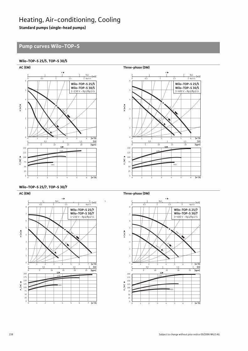
158 Subject to change without prior notice 09/2006 WILO AG
Heating, Air-conditioning, CoolingStandard pumps (single-head pumps)
Pump curves Wilo-TOP-S
Wilo-TOP-S 25/5, TOP-S 30/5
AC (EM) Three-phase (DM)
Wilo-TOP-S 25/7, TOP-S 30/7
AC (EM) Three-phase (DM)
0 1 2 3 4 5 6
0 1 2 3 4 5 6 [m 3/h]
P1 [
W]
H [m
]
Q
[m 3/h]
150
125
100
75
50
25
0
6
5
4
3
2
1
0
Wilo-TOP-S 25/5Wilo-TOP-S 30/51~230 V - Rp1/Rp11/4
0 0,5 1 1,5
0 5 10 15 20 [lgpm]
[l/s]
min. (3 )
(2 )
min.
max.
0 1 2 3
0 0,5 1 1,5 2
v
[m/s]Rp1
Rp11/4
max. (1 )
0 0,5 1 1,5
0 5 10 15 20 [lgpm]
[l/s]0 1 2 3 4 5 6
0 1 2 3 4 5 6 [m 3/h]
P1 [
W]
H [m
]
Q
[m 3/h]
150
125
100
75
50
25
0
6
5
4
3
2
1
0
Wilo-TOP-S 25/5Wilo-TOP-S 30/53~400 V - Rp1/Rp11/4
min. (3 )
(2 )
min.
max.
0 1 2 3
0 0,5 1 1,5 2
v
[m/s]Rp1
Rp11/4
max. (1 )
2 3 Rp1
0 0,5 1 1,5 2
0 5 10 15 20 25
0 1 2 3 4 5 6 7
0 1 2 3 4 5 6 7
v
[m 3/h]
P1 [
W ]
H [m
]
Q
[m 3/h]
[lgpm]
200
175
150
125
100
75
50
25
0
8
7
6
5
4
3
2
1
0
[l/s]
min.
max.
Wilo-TOP-S 25/7Wilo-TOP-S 30/71~230 V - Rp1/Rp11/4
max. (1 )
(2 )
0 0,5 1 1,5 2 Rp11/4
[m/s]0 1
min. (3 )
200
175
150
125
100
75
50
25
0
0 0,5 1 1,5 2
0 5 10 15 20 25
0 1 2 3 4 5 6 7
0 1 2 3 4 5 6 7 [m 3/h]
P1 [
W ]
H [m
]
Q
[m 3/h]
[lgpm]
8
7
6
5
4
3
2
1
0
[l/s]
min.
max.
min. (3 )
(2 )
max. (1 )
Wilo-TOP-S 25/7Wilo-TOP-S 30/73~400 V - Rp1/Rp11/4
2 3 Rp1v
0 0,5 1 1,5 2 Rp11/4
[m/s]
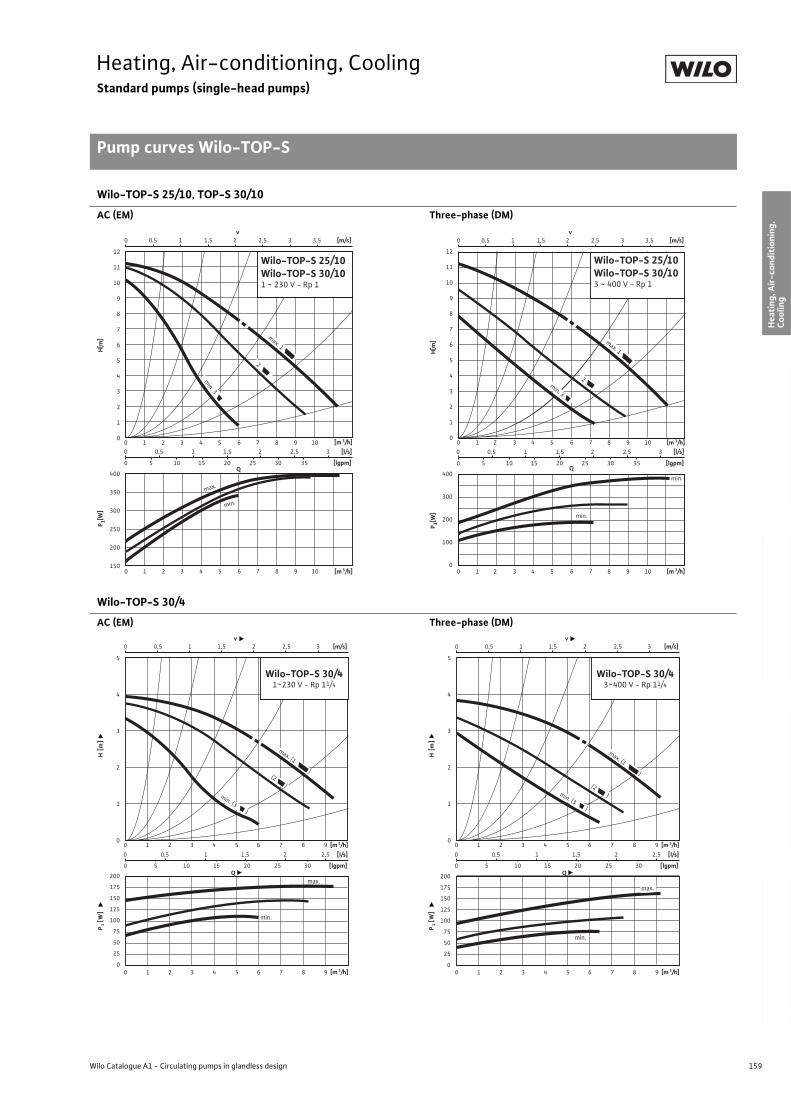
159
Heating, Air-conditioning, CoolingStandard pumps (single-head pumps)
Pump curves Wilo-TOP-S
Wilo Catalogue A1 - Circulating pumps in glandless design
Hea
tin
g, A
ir-c
on
dit
ion
ing
, C
oo
ling
Po
tab
le w
ater
cir
cula
tio
nSo
lar
ther
mal
Serv
ice/
Acc
esso
ries
, Sys
tem
sSw
itch
gea
rs a
nd
Co
ntr
ol
Dev
ices
P
um
p M
anag
emen
t S y
stem
s
Wilo-TOP-S 25/10, TOP-S 30/10
AC (EM) Three-phase (DM)
Wilo-TOP-S 30/4
AC (EM) Three-phase (DM)
0 0,5 1 1,5 2 2,5 3
0 5 10 15 20 25 30 35
0 1 2 3 4 5 6 7 8 9 10
0 1 2 3 4 5 6 7 8 9 10 [m 3/h]
Q
[m 3/h]
[lgpm]
400
350
300
250
200
150
12
11
10
9
8
7
6
5
4
3
2
1
0
[l/s]
min.
max.
min. 3
max. 1
2
0 0,5 1 1,5 2 2,5 3 3,5v
[m/s]
Wilo-TOP-S 25/10Wilo-TOP-S 30/101 ~ 230 V - Rp 1
H[m
]P 1[W
]
0 1 2 3 4 5 6 7 8 9 10
H[m
]
[m 3/h]0 0,5 1 1,5 2 2,5 3
0 5 10 15 20 25 30 35 [lgpm]
[l/s]
400
300
200
100
00 1 2 3 4 5 6 7 8 9 10 [m 3/h]
P 1[W]
Q
min.
min.
0 0,5 1 1,5 2 2,5 3 3,5v
[m/s]
max. 1
2
12
11
10
9
8
7
6
5
4
3
2
1
0
min. 3
Wilo-TOP-S 25/10Wilo-TOP-S 30/103 ~ 400 V - Rp 1
0 0,5 1 1,5 2 2,5
0 5 10 15 20 25 30
0 1 2 3 4 5 6 7 8 9
0 1 2 3 4 5 6 7 8 9 [m 3/h]
P1 [
W]
H [m
]
Q
[m 3/h]
[lgpm]
200
175
150
125
100
75
50
25
0
5
4
3
2
1
0
[l/s]
Wilo-TOP-S 30/41~230 V - Rp 11/4
max. (1 )
min. (3 )
(2 )
min.
max.
0 0,5 1 1,5 2 2,5 3v
[m/s]
0 0,5 1 1,5 2 2,5
0 5 10 15 20 25 30
0 1 2 3 4 5 6 7 8 9
0 1 2 3 4 5 6 7 8 9 [m 3/h]
P1 [
W]
H [m
]
Q
[m 3/h]
[lgpm]
200
175
150
125
100
75
50
25
0
5
4
3
2
1
0
[l/s]
Wilo-TOP-S 30/43~400 V - Rp 11/4
max. (1 )
min. (3 )
(2 )
min.
0 0,5 1 1,5 2 2,5 3v
[m/s]
max.
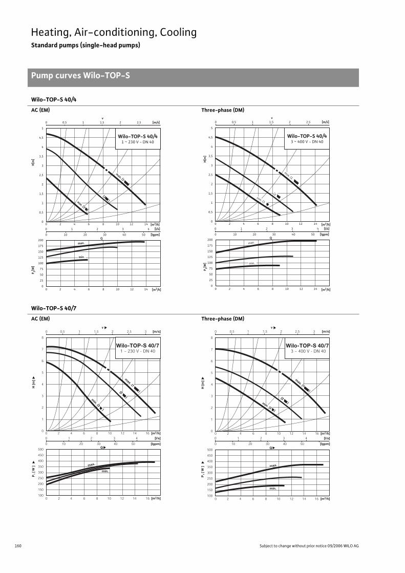
160 Subject to change without prior notice 09/2006 WILO AG
Heating, Air-conditioning, CoolingStandard pumps (single-head pumps)
Pump curves Wilo-TOP-S
Wilo-TOP-S 40/4
AC (EM) Three-phase (DM)
Wilo-TOP-S 40/7
AC (EM) Three-phase (DM)
0 1 2 3 4
0 10 20 30 40 50
0 0,5 1 1,5 2 2,5
0 2 4 6 8 10 12 14
0 2 4 6 8 10 12 14
v [m/s]
Q [lgpm]
200
175
150
125
100
75
50
25
0
5
4,5
4
3,5
3
2,5
2
1,5
1
0,5
0
[l/s]
max.
min.
Wilo-TOP-S 40/41 ~ 230 V - DN 40
[m3/h]
[m3/h]
P 1[W]
H[m
]
max. (1 )
min. (3 )
(2 )
0 2 4 6 8 10 12 14
Q 200
175
150
125
100
75
50
25
0
max.
0 2 4 6 8 10 12 14
5
4,5
4
3,5
3
2,5
2
1,5
1
0,5
0
Wilo-TOP-S 40/43 ~ 400 V - DN 40
0 1 2 3 4
0 10 20 30 40 50 [lgpm]
[l/s]
0 0,5 1 1,5 2 2,5 v
[m/s]
min.
P 1[W]
H[m
]
[m3/h]
[m3/h]
min. (3 )
max. (1 )
(2 )
0 1 2 3 4
0 10 20 30 40 50
0 0,5 1 1,5 2 2,5 3
0 2 4 6 8 10 12 14 16
0 2 4 6 8 10 12 14 16
v [m/s]
[m3/h]
P1
[ W
]H
[m
]
Q
[m3/h]
[lgpm]
500
450
400
350
300
250
200
150
100
8
7
6
5
4
3
2
1
0
[l/s]
min.
max.
Wilo-TOP-S 40/71 ~ 230 V - DN 40
max. (1 )
min. (3 )
(2 )
500
450
400
350
300
250
200
150
100
0 1 2 3 4
0 10 20 30 40 50
0 0,5 1 1,5 2 2,5 3
0 2 4 6 8 10 12 14 16
0 2 4 6 8 10 12 14 16
v [m/s]
[m3/h]
P1
[ W
]H
[m
]
Q
[m3/h]
[lgpm]
8
7
6
5
4
3
2
1
0
[l/s]
min.
Wilo-TOP-S 40/7 3 ~ 400 V - DN 40
min. (3 )
(2 )
max. (1 )
max.
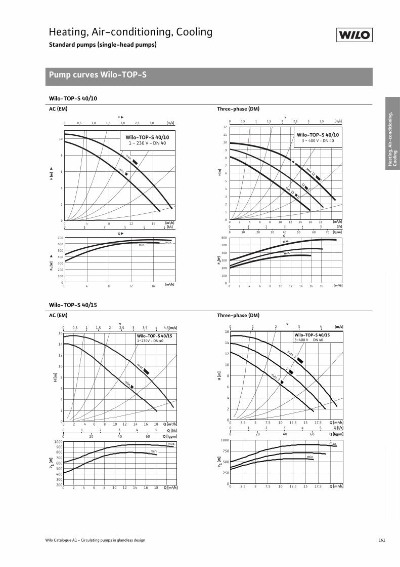
161
Heating, Air-conditioning, CoolingStandard pumps (single-head pumps)
Pump curves Wilo-TOP-S
Wilo Catalogue A1 - Circulating pumps in glandless design
Hea
tin
g, A
ir-c
on
dit
ion
ing
, C
oo
ling
Po
tab
le w
ater
cir
cula
tio
nSo
lar
ther
mal
Serv
ice/
Acc
esso
ries
, Sys
tem
sSw
itch
gea
rs a
nd
Co
ntr
ol
Dev
ices
P
um
p M
anag
emen
t S y
stem
s
Wilo-TOP-S 40/10
AC (EM) Three-phase (DM)
Wilo-TOP-S 40/15
AC (EM) Three-phase (DM)
0 4 8 12 160
100
200
300
400
500
600
700
Q
max.min.
0 0,5 1,0 1,5 2,0 2,5 3,0
0 1 2 3 4 5
v
0
2
4
6
8
10
0 4 8 12 16
max.
min.
Wilo-TOP-S 40/101 ~ 230 V - DN 40
H [m
]P 1
[W]
[m3/h]
[m3/h]
[m/s]
[l/s] 0 1 2 3 4 5
0 10 20 30 40 50 60 70
0 2 4 6 8 10 12 14 16 18
0 2 4 6 8 10 12 14 16 18
Q [lgpm]
600
500
400
300
200
100
0
12
11
10
9
8
7
6
5
4
3
2
1
0
[l/s]
max.
Wilo-TOP-S 40/103 ~ 400 V - DN 40
0 0,5 1 1,5 2 2,5 3 3,5 v
[m/s]
max. (1 ) (2 )
min. (3 )
min.
[m3/h]
[m3/h] P 1[W
] H
[m]
2 4 8 12 16 18 Q [m³/h]
Q [l/s]
0
2
4
6
8
10
12
14
16
H [m
]
0 20 40 60 Q [Igpm]
200
300
400
500
600
700
800
900
1000
0
0 1 2 3 4 5
6 10 14
2 4 60 10 12 14 16 188 Q [m³/h]
P 1 [W]
0 0,5 1,51 2,52 3,53 4,54 [m/s]v
Wilo-TOP-S 40/151~230V - DN 40
max.
min.
max.
min.
0 1 2 3 4 [m/s]
0
2
4
6
8
10
12
14
16
2,5 7,5 12,5 17,5 Q [m³/h]
H [m
]
0 1 2 3 4 5 Q [l/s]
0 20 40 60 Q [Igpm]
0
250
500
750
1000
2,5 7,5 12,5
0
0
5 10 15
5 10 15 17,5 Q [m³/h]
P 1 [W]
v
min.
Wilo-TOP-S 40/153~400 V DN 40
2
max. 1
max.
min. 3
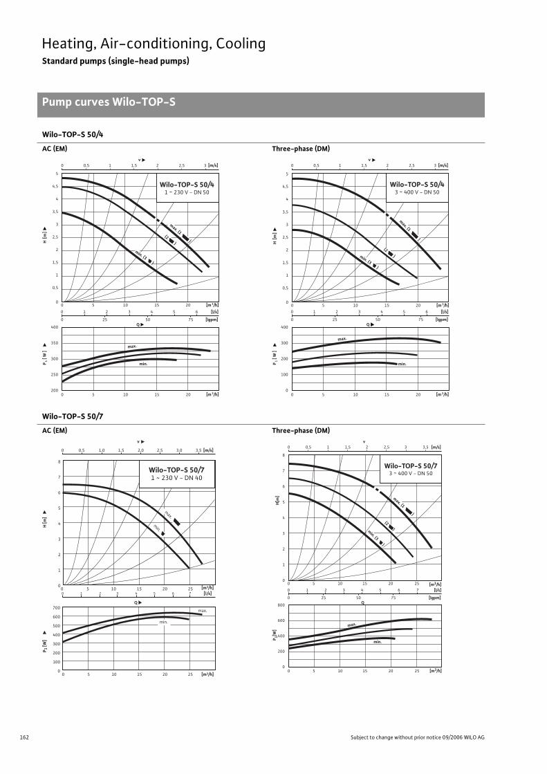
162 Subject to change without prior notice 09/2006 WILO AG
Heating, Air-conditioning, CoolingStandard pumps (single-head pumps)
Pump curves Wilo-TOP-S
Wilo-TOP-S 50/4
AC (EM) Three-phase (DM)
Wilo-TOP-S 50/7
AC (EM) Three-phase (DM)
0 1 2 3 4 5 6
0 25 50 75
0 0,5 1 1,5 2 2,5 3
0 5 10 15 20
0 5 10 15 20
v [m/s]
[m 3/h]
P1 [
W ]
H [m
]
Q
[m 3/h]
[lgpm]
400
350
300
250
200
5
4,5
4
3,5
3
2,5
2
1,5
1
0,5
0
[l/s]
min.
Wilo-TOP-S 50/41 ~ 230 V - DN 50
max.
max. (1 )(2 )
min. (3 )
400
300
200
100
0
0 5 10 15 20
0 5 10 15 20 [m 3/h]
P1 [
W ]
H [m
]
[m 3/h]
5
4,5
4
3,5
3
2,5
2
1,5
1
0,5
0
max.
min. (3 )
max. (1 )
Wilo-TOP-S 50/43 ~ 400 V - DN 50
min.
0 1 2 3 4 5 6
0 25 50 75Q
[lgpm]
[l/s]
0 0,5 1 1,5 2 2,5 3 v
[m/s]
(2 )
0
1
2
3
4
5
6
7
8
0
100
200
300
400
500
600
700
0 5 10 15 20 25
0 0,5 1,0 1,5 2,0 2,5 3,0 3,5
0 1 2 3 4 5 6 7
0 5 10 15 20 25
v
Q
max.
min.
Wilo-TOP-S 50/71 ~ 230 V - DN 40
max.
min.
H [m
]P 1
[W]
[m3/h]
[m3/h]
[m/s]
[l/s]0 1 2 3 4 5 6 7
0 25 50 75
0 0,5 1 1,5 2 2,5 3 3,5
0 5 10 15 20 25
0 5 10 15 20 25
v [m/s]
Q [lgpm]
800
600
400
200
0
8
7
6
5
4
3
2
1
0
[l/s]
min.
max.
Wilo-TOP-S 50/73 ~ 400 V - DN 50
min. (3 )
(2 )
max. (1 )
[m3/h]
[m3/h]
P 1[W]
H[m
]
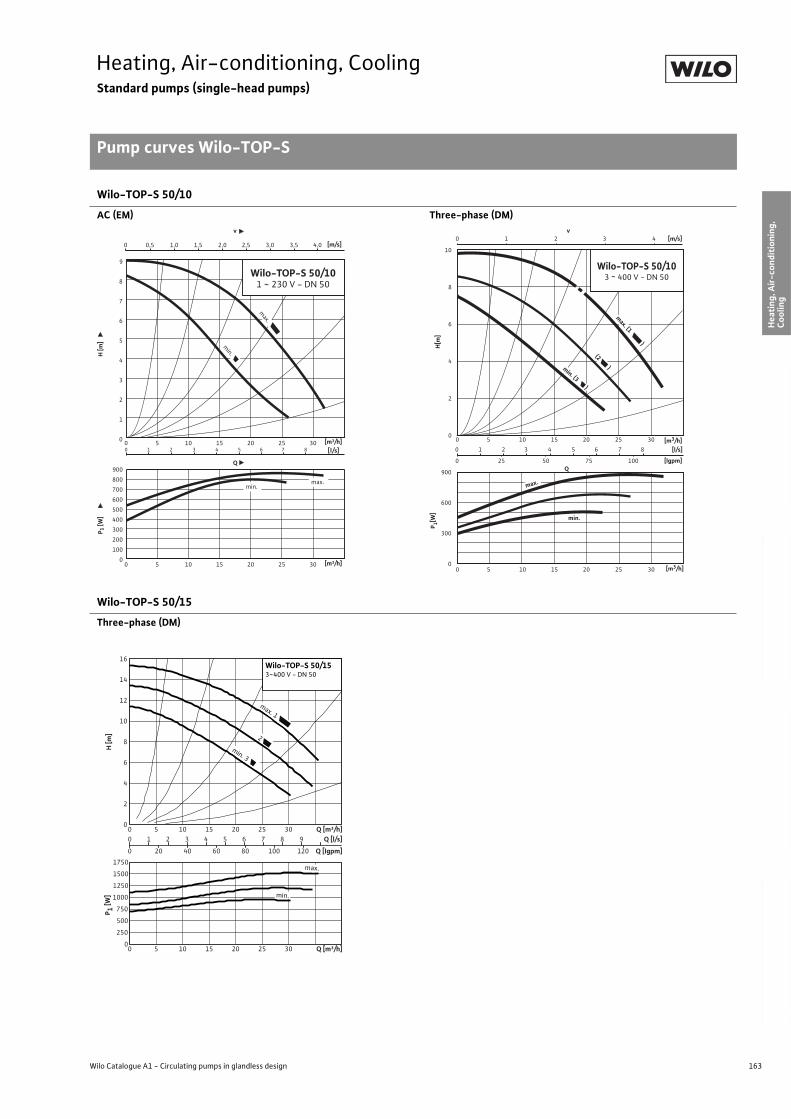
163
Heating, Air-conditioning, CoolingStandard pumps (single-head pumps)
Pump curves Wilo-TOP-S
Wilo Catalogue A1 - Circulating pumps in glandless design
Hea
tin
g, A
ir-c
on
dit
ion
ing
, C
oo
ling
Po
tab
le w
ater
cir
cula
tio
nSo
lar
ther
mal
Serv
ice/
Acc
esso
ries
, Sys
tem
sSw
itch
gea
rs a
nd
Co
ntr
ol
Dev
ices
P
um
p M
anag
emen
t S y
stem
s
Wilo-TOP-S 50/10
AC (EM) Three-phase (DM)
Wilo-TOP-S 50/15
Three-phase (DM)
0
1
2
3
4
5
6
7
8
9
0
100
200
300
400
500
600
700
800
900
0 5 10 15 20 25 30
0 5 10 15 20 25 300 1 2 3 4 5 6 7 8
0 0,5 1,0 1,5 2,0 2,5 3,0 3,5 4,0
v
Wilo-TOP-S 50/101 ~ 230 V - DN 50
Q
max.
min.
max.min.
H [m
]P 1
[W]
[m3/h]
[m3/h]
[m/s]
[l/s]
900
600
300
0
0 5 10 15 20 25 30
0 5 10 15 20 25 30
Q
10
8
6
4
2
0
min.
0 1 2 3 4 5 6 7 8
0 25 50 75 100 [lgpm]
[l/s]
0 1 2 3 4 v
[m/s]
Wilo-TOP-S 50/103 ~ 400 V - DN 50
max.
(2 )
max. (1 )
min. (3 )
[m3/h]
[m3/h] P 1[W
] H
[m]
0
2
4
6
8
10
12
14
16
0 5 10 15 20 25 30 Q [m³/h]
H [m
]
0 1 2 3 4 5 6 7 8 9 Q [l/s]
0 20 40 60 80 100 120 Q [Igpm]
0
250
500
750
1000
1250
1500
1750
0 5 10 15 20 25 30 Q [m³/h]
P 1 [W]
min. 3
2
max. 1
Wilo-TOP-S 50/153~400 V - DN 50
min.
max.
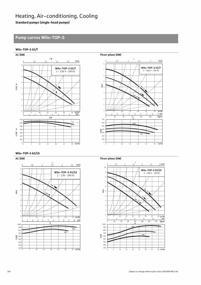
164 Subject to change without prior notice 09/2006 WILO AG
Heating, Air-conditioning, CoolingStandard pumps (single-head pumps)
Pump curves Wilo-TOP-S
Wilo-TOP-S 65/7
AC (EM) Three-phase (DM)
Wilo-TOP-S 65/10
AC (EM) Three-phase (DM)
0
1
2
3
4
5
6
7
8
0
100
200
300
400
500
600
700
0 5 10 15 20 25 30
0 5 10 15 20 25 30
0 1 2 3 4 5 6 7 8
0 0,5 1,0 1,5 2,0
v[m/s]
[l/s]
Wilo-TOP-S 65/71 ~ 230 V - DN 65
Q
max.
min.
max.
min.
H [m
]P 1
[W]
[m3/h]
[m3/h]
0 1 2 3 4 5 6 7 8 9
0 20 40 60 80 100
0 0,5 1 1,5 2
0 5 10 15 20 25 30
0 5 10 15 20 25 30
v [m/s]
Q [lgpm]
700
600
500
400
300
200
100
0
8
7
6
5
4
3
2
1
0
[l/s]
min.
Wilo-TOP-S 65/73 ~ 400 V - DN 65
max.
min. (3 )
(2 )
max. (1 )
[m3/h]
[m3/h]
P 1[W]
H[m
]
0
1
2
3
4
5
6
7
8
9
0 1 2 3 4 5 6 7 8 9 10
Wilo-TOP-S 65/101 ~ 230 - DN 65
Q
max.
min.
max.
min.
1000
900
800
700
600
500
400
300
200
0 5 10 15 20 25 30 35
0 5 10 15 20 25 30 35
0 0,5 1 1,5 2 2,5v
[m/s]
[l/s]
[m3/h]
[m3/h]
P 1[W]
H[m
]
1000
900
800
700
600
500
400
300
200
0 2 4 6 8 10
0 20 40 60 80 100 120 140
0 0,5 1 1,5 2 2,5 3
0 5 10 15 20 25 30 35 40
0 5 10 15 20 25 30 35 40
v [m/s]
Q [lgpm]
10
9
8
7
6
5
4
3
2
1
0
[l/s]
min.
Wilo-TOP-S 65/10 3 ~ 400 V - DN 65
max.
(2 ) min. (3 )
max. (1 )
[m3/h]
[m3/h]
P 1[W]
H[m
]
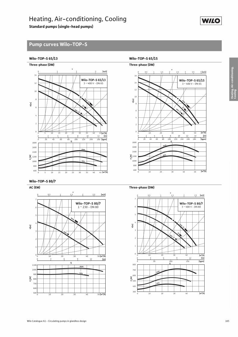
165
Heating, Air-conditioning, CoolingStandard pumps (single-head pumps)
Pump curves Wilo-TOP-S
Wilo Catalogue A1 - Circulating pumps in glandless design
Hea
tin
g, A
ir-c
on
dit
ion
ing
, C
oo
ling
Po
tab
le w
ater
cir
cula
tio
nSo
lar
ther
mal
Serv
ice/
Acc
esso
ries
, Sys
tem
sSw
itch
gea
rs a
nd
Co
ntr
ol
Dev
ices
P
um
p M
anag
emen
t S y
stem
s
Wilo-TOP-S 65/13 Wilo-TOP-S 65/15
Three-phase (DM) Three-phase (DM)
Wilo-TOP-S 80/7
AC (EM) Three-phase (DM)
0 2 4 6 8 10 12
0 20 40 60 80 100 120 140 160
0 1 2 3
0 5 10 15 20 25 30 35 40 45
0 5 10 15 20 25 30 35 40 45
v [m/s]
Q[lgpm]
1800
1600
1400
1200
1000
800
600
14
12
10
8
6
4
2
0
[l/s]
Wilo-TOP-S 65/133 ~ 400 V - DN 65
max.
min. (3 )
(2 )
max. (1 )
min.
[m3/h]
[m3/h]
P 1[W]
H[m
]
1800
1600
1400
1200
1000
800
600
0 2 4 6 8 10 12 14
0 20 40 60 80 100 120 140 160 180
0 0,5 1 1,5 2 2,5 3 3,5 4
0 10 20 30 40 50
0 10 20 30 40 50
v [m/s]
Q [lgpm]
16
14
12
10
8
6
4
2
0
[l/s]
min.
max.
Wilo-TOP-S 65/153 ~ 400 V - DN 65
max. (1 ) (2 )
min. (3 )
[m3/h]
[m3/h] P 1[W
] H
[m]
0
1
2
3
4
5
6
7
0 10
0 3 6 9 12
20 30 40 50
Wilo-TOP-S 80/71 ~ 230 - DN 80
Q
max.
min.
max.
min.
1100
1000
900
800
700
600
500
0 0,5 1 1,5 2 2,5
v[m/s]
[l/s]
[m3/h]
0 10 20 30 40 50 [m3/h]
P 1[W]
H[m
]
0 3 6 9 12
0 50 100 150
0 0,5 1 1,5 2 2,5
0 10 20 30 40
0 10 20 30 40
v [m/s]
Q [lgpm]
800
700
600
500
400
300
7
6
5
4
3
2
1
0
[l/s]
min.
Wilo-TOP-S 80/73 ~ 400 V - DN 80
max.
max. (1 )
min. (3 )
(2 )
[m3/h]
[m3/h]
P 1[W]
H[m
]
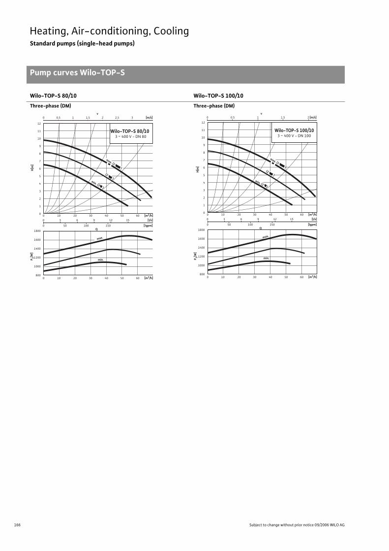
166 Subject to change without prior notice 09/2006 WILO AG
Heating, Air-conditioning, CoolingStandard pumps (single-head pumps)
Pump curves Wilo-TOP-S
Wilo-TOP-S 80/10 Wilo-TOP-S 100/10
Three-phase (DM) Three-phase (DM)
1800
1600
1400
1200
1000
800
0 3 6 9 12 15
0 50 100 150
0 0,5 1 1,5 2 2,5 3
0 10 20 30 40 50 60
0 10 20 30 40 50 60
v [m/s]
Q [lgpm]
12
11
10
9
8
7
6
5
4
3
2
1
0
[l/s]
min.
Wilo-TOP-S 80/10 3 ~ 400 V - DN 80
(2 )
max. (1 )
min. (3 )
max.
[m3/h]
[m3/h]
P 1[W]
H[m
]
0 0,5 1 1,5 2 v
[m/s]
1800
1600
1400
1200
1000
800
0 3 6 9 12 15
0 50 100 150
0 10 20 30 40 50 60
0 10 20 30 40 50 60
Q [lgpm]
12
11
10
9
8
7
6
5
4
3
2
1
0
[l/s]
min.
max.
(2 )
max. (1 )
min. (3 )
Wilo-TOP-S 100/103 ~ 400 V - DN 100
[m3/h]
[m3/h]
P 1[W]
H[m
]

167
Heating, Air-conditioning, CoolingStandard pumps (single-head pumps)
Terminal Diagrams Wilo-TOP-S
Wilo Catalogue A1 - Circulating pumps in glandless design
Hea
tin
g, A
ir-c
on
dit
ion
ing
, C
oo
ling
Po
tab
le w
ater
cir
cula
tio
nSo
lar
ther
mal
Serv
ice/
Acc
esso
ries
, Sys
tem
sSw
itch
gea
rs a
nd
Co
ntr
ol
Dev
ices
P
um
p M
anag
emen
t S y
stem
s
Terminal diagram A/motor protection A Terminal diagram B/motor protection B
Mains connection 1~230 V, 50 Hz Mains connection 3~400 V, 50 Hz3~230 V, 50 Hz (with optional switching plug 3~230 V)
Internal protection against unacceptably high winding temperaturesTripping: Internal interruption of motor voltageReset: Automatic after motor has cooled down
Internal protection against unacceptably high winding temperaturesTripping: Internal interruption of motor phaseReset: Interrupt mains system voltage, allow motor to cool
down, switch mains system voltage on again
Terminal diagram C/motor protection C Terminal diagram D/motor protection D
Mains connection 1~230 V, 50 Hz Mains connection 3~400 V, 50 Hz3~230 V, 50 Hz (with optional switching plug 3~230 V)
WSK = Thermal winding contactFull motor protection in all speed stages with optional Wilo-SK 602/SK 622/Protect-Module C tripping unit or other switchgears/control devices with WSK connection optionTripping: External tripping at switchgear/control deviceReset: Manual reset at switchgear/control device necessary
(circuit diagram with SK 602/622, see “Service/Accessories”)
Full motor protection with integrated trip electronics in terminal box for all speed stagesTripping: All-pole shutdown of motor by integrated tripping
electronicsReset: Manual reset at terminal box necessary
Load capacity of the potential-free NC contact in accordance with VDI 3814 for die collective fault signal (SSM) 1 A, 250 V ~For function, see chapter “Pump Management Systems Wilo-Control, Planning Guide”
Terminal diagram E/motor protection E
Mains connection 1~230 V, 50 Hz
Full motor protection with integrated trip electronics in terminal box for all speed stagesTripping: All-pole shutdown of motor by integrated automatic
trippingReset: Manual reset at terminal box necessary
Load capacity of the potential-free NC contact in accordance with VDI 3814 only for collective fault signal (SSM) 1 A, 250 V~For function, see chapter “Pump Management Systems Wilo-Control, Planning Guide”
L NPE
NL
L1 L2PE
L2
L3
L3L1
L NPE
NL
WSK
WSK
L1 L2 L3PE
L1 L2 L3
SSM
SSM
C2 N LPEC1
C1SSM LC2 N
SSM
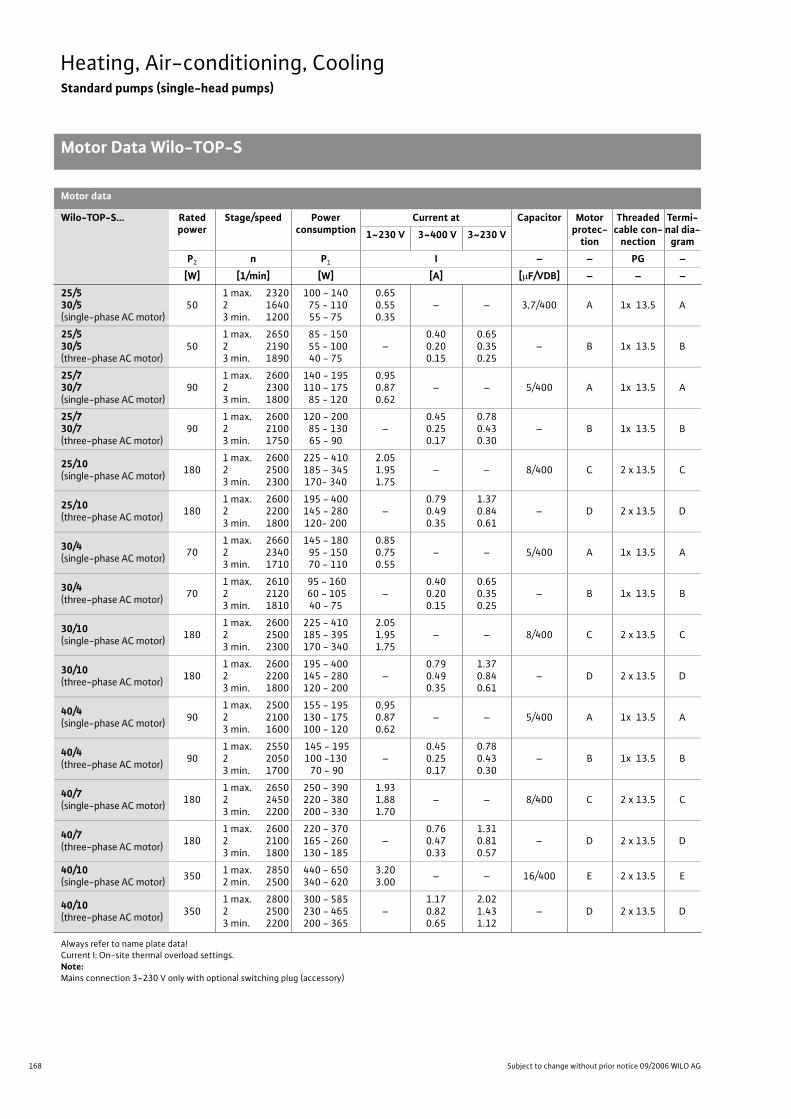
168 Subject to change without prior notice 09/2006 WILO AG
Heating, Air-conditioning, CoolingStandard pumps (single-head pumps)
Motor Data Wilo-TOP-S
Motor data
Wilo-TOP-S... Rated power
Stage/speed Power consumption
Current at Capacitor Motor protec-
tion
Threaded cable con-
nection
Termi-nal dia-
gram1~230 V 3~400 V 3~230 V
P2 n P1 I – – PG –
[W] [1/min] [W] [A] [ F/VDB] – – –
25/530/5(single-phase AC motor)
501 max. 2320 2 16403 min. 1200
100 - 140 75 - 110
55 - 75
0.650.550.35
– – 3,7/400 A 1x 13.5 A
25/530/5(three-phase AC motor)
501 max. 2650 2 21903 min. 1890
85 - 150 55 - 100
40 - 75–
0.400.200.15
0.650.350.25
– B 1x 13.5 B
25/730/7(single-phase AC motor)
901 max. 2600 2 23003 min. 1800
140 - 195110 - 175 85 - 120
0.950.870.62
– – 5/400 A 1x 13.5 A
25/730/7(three-phase AC motor)
901 max. 2600 2 21003 min. 1750
120 - 200 85 - 130
65 - 90–
0.450.250.17
0.780.430.30
– B 1x 13.5 B
25/10(single-phase AC motor)
1801 max. 2600 2 25003 min. 2300
225 - 410185 - 345170- 340
2.051.951.75
– – 8/400 C 2 x 13.5 C
25/10(three-phase AC motor)
1801 max. 2600 2 22003 min. 1800
195 - 400145 - 280120- 200
–0.790.490.35
1.370.840.61
– D 2 x 13.5 D
30/4(single-phase AC motor)
701 max. 2660 2 23403 min. 1710
145 - 180 95 - 150 70 - 110
0.850.750.55
– – 5/400 A 1x 13.5 A
30/4(three-phase AC motor)
701 max. 2610 2 21203 min. 1810
95 - 160 60 - 10540 - 75
–0.400.200.15
0.650.350.25
– B 1x 13.5 B
30/10(single-phase AC motor)
1801 max. 2600 2 25003 min. 2300
225 - 410185 - 395170 - 340
2.051.951.75
– – 8/400 C 2 x 13.5 C
30/10(three-phase AC motor)
1801 max. 2600 2 22003 min. 1800
195 - 400145 - 280120 - 200
–0.790.490.35
1.370.840.61
– D 2 x 13.5 D
40/4(single-phase AC motor)
901 max. 2500 2 21003 min. 1600
155 - 195130 - 175100 - 120
0.950.870.62
– – 5/400 A 1x 13.5 A
40/4(three-phase AC motor)
901 max. 2550 2 20503 min. 1700
145 - 195100 -130 70 - 90
–0.450.250.17
0.780.430.30
– B 1x 13.5 B
40/7(single-phase AC motor)
1801 max. 2650 2 24503 min. 2200
250 - 390220 - 380200 - 330
1.931.881.70
– – 8/400 C 2 x 13.5 C
40/7(three-phase AC motor)
1801 max. 2600 2 21003 min. 1800
220 - 370165 - 260130 - 185
–0.760.470.33
1.310.810.57
– D 2 x 13.5 D
40/10(single-phase AC motor)
3501 max. 2850 2 min. 2500
440 - 650340 - 620
3.203.00
– – 16/400 E 2 x 13.5 E
40/10(three-phase AC motor)
3501 max. 2800 2 25003 min. 2200
300 - 585230 - 465200 - 365
–1.170.820.65
2.021.431.12
– D 2 x 13.5 D
Always refer to name plate data!Current I: On-site thermal overload settings.Note:Mains connection 3~230 V only with optional switching plug (accessory)
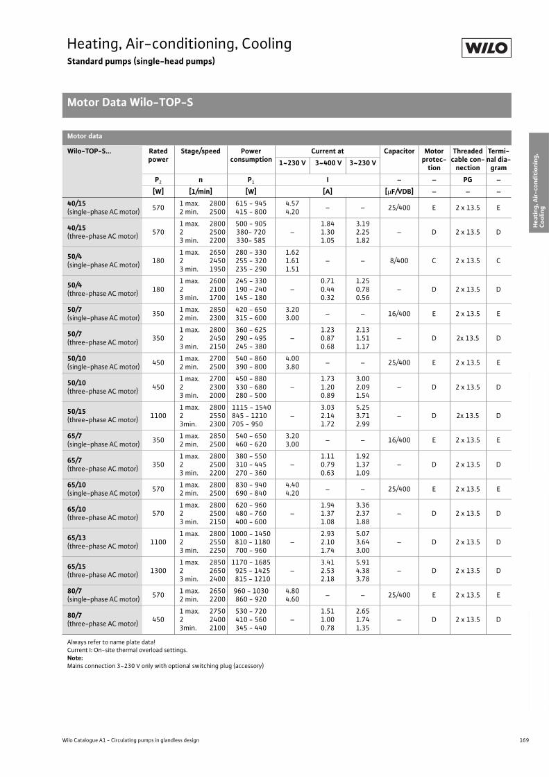
169
Heating, Air-conditioning, CoolingStandard pumps (single-head pumps)
Motor Data Wilo-TOP-S
Wilo Catalogue A1 - Circulating pumps in glandless design
Hea
tin
g, A
ir-c
on
dit
ion
ing
, C
oo
ling
Po
tab
le w
ater
cir
cula
tio
nSo
lar
ther
mal
Serv
ice/
Acc
esso
ries
, Sys
tem
sSw
itch
gea
rs a
nd
Co
ntr
ol
Dev
ices
P
um
p M
anag
emen
t S y
stem
s
40/15(single-phase AC motor)
5701 max. 2800 2 min. 2500
615 - 945415 - 800
4.574.20
– – 25/400 E 2 x 13.5 E
40/15(three-phase AC motor)
5701 max. 2800 2 25003 min. 2200
500 - 905380- 720330- 585
–1.841.301.05
3.192.251.82
– D 2 x 13.5 D
50/4(single-phase AC motor)
1801 max. 2650 2 24503 min. 1950
280 - 330255 - 320235 - 290
1.621.611.51
– – 8/400 C 2 x 13.5 C
50/4(three-phase AC motor)
1801 max. 2600 2 21003 min. 1700
245 - 330190 - 240145 - 180
–0.710.440.32
1.250.780.56
– D 2 x 13.5 D
50/7(single-phase AC motor)
3501 max. 2850 2 min. 2300
420 - 650315 - 600
3.203.00
– – 16/400 E 2 x 13.5 E
50/7(three-phase AC motor)
3501 max. 2800 2 24503 min. 2150
360 - 625290 - 495245 - 380
–1.230.870.68
2.131.511.17
– D 2x 13.5 D
50/10(single-phase AC motor)
4501 max. 2700 2 min. 2500
540 - 860390 - 800
4.003.80
– – 25/400 E 2 x 13.5 E
50/10(three-phase AC motor)
4501 max. 2700 2 23003 min. 2000
450 - 880330 - 680280 - 500
–1.731.200.89
3.002.091.54
– D 2 x 13.5 D
50/15(three-phase AC motor)
11001 max. 2800 2 25503min. 2300
1115 - 1540845 - 1210705 - 950
–3.032.141.72
5.253.712.99
– D 2x 13.5 D
65/7(single-phase AC motor)
3501 max. 2850 2 min. 2500
540 - 650460 - 620
3.203.00
– – 16/400 E 2 x 13.5 E
65/7(three-phase AC motor)
3501 max. 2800 2 25003 min. 2200
380 - 550310 - 445270 - 360
–1.110.790.63
1.921.371.09
– D 2 x 13.5 D
65/10(single-phase AC motor)
5701 max. 2800 2 min. 2500
830 - 940690 - 840
4.404.20
– – 25/400 E 2 x 13.5 E
65/10(three-phase AC motor)
5701 max. 2800 2 25003 min. 2150
620 - 960480 - 760400 - 600
–1.941.371.08
3.362.371.88
– D 2 x 13.5 D
65/13(three-phase AC motor)
11001 max. 2800 2 25503 min. 2250
1000 - 1450 810 - 1180
700 - 960–
2.932.101.74
5.073.643.00
– D 2 x 13.5 D
65/15(three-phase AC motor)
13001 max. 2850 2 26503 min. 2400
1170 - 1685 925 - 1425 815 - 1210
–3.412.532.18
5.914.383.78
– D 2 x 13.5 D
80/7(single-phase AC motor)
5701 max. 2650 2 min. 2200
960 - 1030860 - 920
4.804.60
– – 25/400 E 2 x 13.5 E
80/7(three-phase AC motor)
4501 max. 2750 2 24003min. 2100
530 - 720410 - 560345 - 440
–1.511.000.78
2.651.741.35
– D 2 x 13.5 D
Motor data
Wilo-TOP-S... Rated power
Stage/speed Power consumption
Current at Capacitor Motor protec-
tion
Threaded cable con-
nection
Termi-nal dia-
gram1~230 V 3~400 V 3~230 V
P2 n P1 I – – PG –
[W] [1/min] [W] [A] [ F/VDB] – – –
Always refer to name plate data!Current I: On-site thermal overload settings.Note:Mains connection 3~230 V only with optional switching plug (accessory)
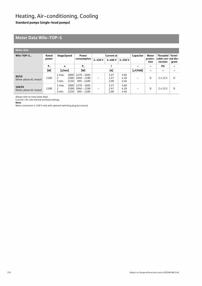
170 Subject to change without prior notice 09/2006 WILO AG
Heating, Air-conditioning, CoolingStandard pumps (single-head pumps)
Motor Data Wilo-TOP-S
80/10(three-phase AC motor)
11001 max. 2800 2 25003 min. 2150
1270 - 16851040 - 1390 895 - 1100
–3.272.472.00
5.664.283.46
– D 2 x 13.5 D
100/10(three-phase AC motor)
11001 max. 2800 2 25003 min. 2150
1270 - 16851040 - 1390 895 - 1100
–3.272.472.00
5.664.283.46
– D 2 x 13.5 D
Motor data
Wilo-TOP-S... Rated power
Stage/speed Power consumption
Current at Capacitor Motor protec-
tion
Threaded cable con-
nection
Termi-nal dia-
gram1~230 V 3~400 V 3~230 V
P2 n P1 I – – PG –
[W] [1/min] [W] [A] [ F/VDB] – – –
Always refer to name plate data!Current I: On-site thermal overload settings.Note:Mains connection 3~230 V only with optional switching plug (accessory)
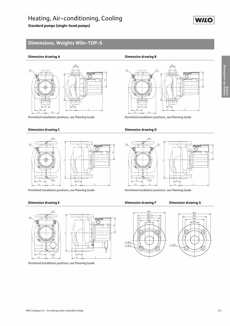
171
Heating, Air-conditioning, CoolingStandard pumps (single-head pumps)
Dimensions, Weights Wilo-TOP-S
Wilo Catalogue A1 - Circulating pumps in glandless design
Hea
tin
g, A
ir-c
on
dit
ion
ing
, C
oo
ling
Po
tab
le w
ater
cir
cula
tio
nSo
lar
ther
mal
Serv
ice/
Acc
esso
ries
, Sys
tem
sSw
itch
gea
rs a
nd
Co
ntr
ol
Dev
ices
P
um
p M
anag
emen
t S y
stem
s
Dimension drawing A Dimension drawing B
Permitted installation positions, see Planning Guide Permitted installation positions, see Planning Guide
Dimension drawing C Dimension drawing D
Permitted installation positions, see Planning Guide Permitted installation positions, see Planning Guide
Dimension drawing E Dimension drawing F Dimension drawing G
Permitted installation positions, see Planning Guide
Pg
Rp
b1
b2 b2
G
l 0
b 3
a2
a1
l1
Pg Pg
Rp
b1
b2 b2
G
l 0
b 3
a2
a1
l1
Pg
l 0
b 3
b1
b2 b2
R 1/8
R 1/8
a1
l1a2
PgPg
l 0
b 3
b1
b2 b2
R 1/8
R 1/8
a1
l1a2
Pg
b1
b2 b2
R 1/8
R 1/8
l 0
b 3
a1
l1a2
Ø D
n x Ø d
Ø k
DN
L2
Ø k Ø d
L 1
1
n x Ø d 2n x Ø d
Ø D Ø k
DN
Ø d
L
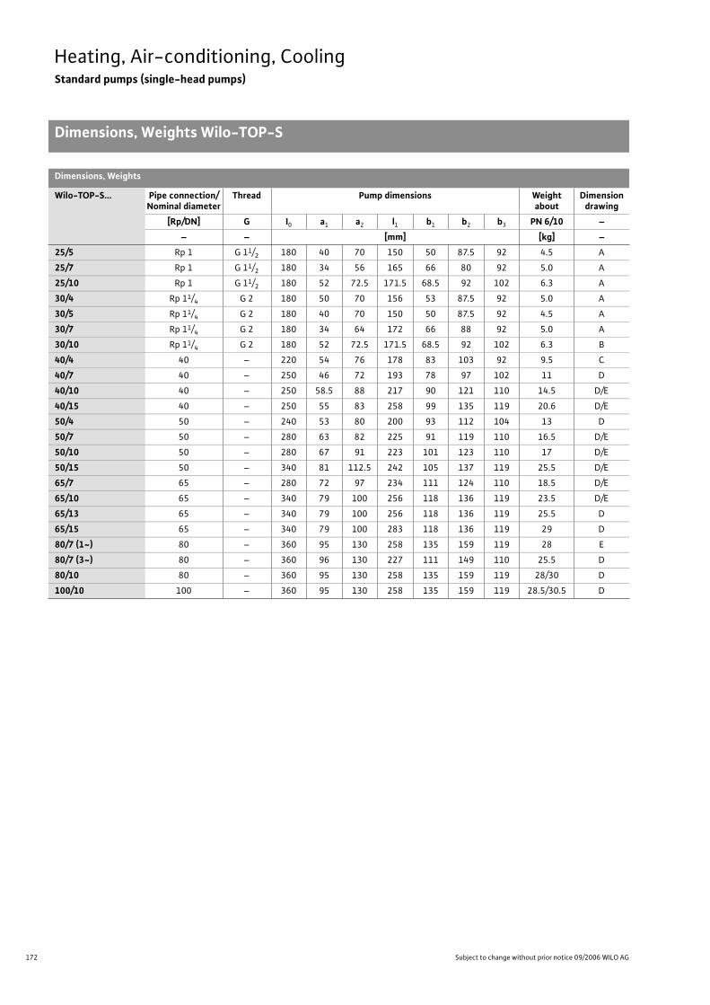
172 Subject to change without prior notice 09/2006 WILO AG
Heating, Air-conditioning, CoolingStandard pumps (single-head pumps)
Dimensions, Weights Wilo-TOP-S
Dimensions, Weights
Wilo-TOP-S... Pipe connection/Nominal diameter
Thread Pump dimensions Weight about
Dimension drawing
[Rp/DN] G I0 a1 a2 l1 b1 b2 b3 PN 6/10 –
– – [mm] [kg] –
25/5 Rp 1 G 11/2 180 40 70 150 50 87.5 92 4.5 A
25/7 Rp 1 G 11/2 180 34 56 165 66 80 92 5.0 A
25/10 Rp 1 G 11/2 180 52 72.5 171.5 68.5 92 102 6.3 A
30/4 Rp 11/4 G 2 180 50 70 156 53 87.5 92 5.0 A
30/5 Rp 11/4 G 2 180 40 70 150 50 87.5 92 4.5 A
30/7 Rp 11/4 G 2 180 34 64 172 66 88 92 5.0 A
30/10 Rp 11/4 G 2 180 52 72.5 171.5 68.5 92 102 6.3 B
40/4 40 – 220 54 76 178 83 103 92 9.5 C
40/7 40 – 250 46 72 193 78 97 102 11 D
40/10 40 – 250 58.5 88 217 90 121 110 14.5 D/E
40/15 40 – 250 55 83 258 99 135 119 20.6 D/E
50/4 50 – 240 53 80 200 93 112 104 13 D
50/7 50 – 280 63 82 225 91 119 110 16.5 D/E
50/10 50 – 280 67 91 223 101 123 110 17 D/E
50/15 50 – 340 81 112.5 242 105 137 119 25.5 D/E
65/7 65 – 280 72 97 234 111 124 110 18.5 D/E
65/10 65 – 340 79 100 256 118 136 119 23.5 D/E
65/13 65 – 340 79 100 256 118 136 119 25.5 D
65/15 65 – 340 79 100 283 118 136 119 29 D
80/7 (1~) 80 – 360 95 130 258 135 159 119 28 E
80/7 (3~) 80 – 360 96 130 227 111 149 110 25.5 D
80/10 80 – 360 95 130 258 135 159 119 28/30 D
100/10 100 – 360 95 130 258 135 159 119 28.5/30.5 D
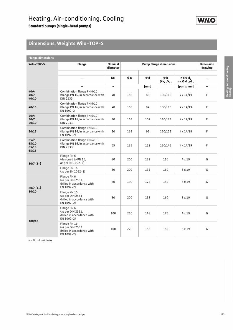
173
Heating, Air-conditioning, CoolingStandard pumps (single-head pumps)
Dimensions, Weights Wilo-TOP-S
Wilo Catalogue A1 - Circulating pumps in glandless design
Hea
tin
g, A
ir-c
on
dit
ion
ing
, C
oo
ling
Po
tab
le w
ater
cir
cula
tio
nSo
lar
ther
mal
Serv
ice/
Acc
esso
ries
, Sys
tem
sSw
itch
gea
rs a
nd
Co
ntr
ol
Dev
ices
P
um
p M
anag
emen
t S y
stem
s
Flange dimensions
Wilo-TOP-S... Flange Nominal diameter
Pump flange dimensions Dimension drawing
– DN Ø D Ø d Ø kØ kL1/kL2
n x Ø dLn x Ø dL1/dL2
–
– – [mm] [pcs. x mm] –
40/440/740/10
Combination flange PN 6/10(flange PN 16, in accordance with DIN 2533)
40 150 88 100/110 4 x 14/19 F
40/15Combination flange PN 6/10(flange PN 16, in accordance with EN 1092-2
40 150 84 100/110 4 x 14/19 F
50/450/750/10
Combination flange PN 6/10(flange PN 16, in accordance with DIN 2533)
50 165 102 110/125 4 x 14/19 F
50/15Combination flange PN 6/10(flange PN 16, in accordance with EN 1092-2)
50 165 99 110/125 4 x 14/19 F
65/765/1065/1365/15
Combination flange PN 6/10(flange PN 16, in accordance with DIN 2533)
65 185 122 130/145 4 x 14/19 F
80/7 (3~)
Flange PN 6(designed to PN 16,as per EN 1092-2)
80 200 132 150 4 x 19 G
Flange PN 16 (as per EN 1092-2)
80 200 132 160 8 x 19 G
80/7 (1~)80/10
Flange PN 6 (as per DIN 2531,drilled in accordance with EN 1092-2)
80 190 128 150 4 x 19 G
Flange PN 16(as per DIN 2533drilled in accordance with EN 1092-2)
80 200 138 160 8 x 19 G
100/10
Flange PN 6 (as per DIN 2531,drilled in accordance with EN 1092-2)
100 210 148 170 4 x 19 G
Flange PN 16(as per DIN 2533drilled in accordance with EN 1092-2)
100 220 158 180 8 x 19 G
n = No. of bolt holes

174 Subject to change without prior notice 09/2006 WILO AG
Heating, Air-conditioning, CoolingStandard pumps (single-head pumps)
Technical Data Wilo-TOP-D
Wilo-TOP-D...
30 40 50 65 80 100 125
Approved fluids(other fluids on request)
Heating water (In accordance with VDI 2035) • • • • • • •
Water/glycol mixtures (max. 1:1; mixtures with more than 20 % glycol content require rechecking of the pumping data)
• • • • • • •
Potable water and water for food businesses in accordance with TrinkwV 2001
– – – – – – –
Performance
Maximum delivery head [m] 0.9 0.95 0.75 0.9 1.8 2.3 3.0
Flow volume max. [m3/h] 4 7 11,5 14 35 51 76
Permitted field of application
Temperature range for utilisation in heating, ventila-tion & air conditioning systems
at max. ambient temperature of +25 °C [°C]at max. ambient temperature +40 °C [°C]
–-20 to +130 (in short-term operation 2 h: 140)
Temperature range for utilisation in potable water circulation systems
at max. ambient temperature +40 °C [°C] – – – – – – –
max. permitted total hardness in potable water cir-culation systems [°d]
– – – – – – –
Standard version for operating pressure pmax [bar] 10 6/10 6/10 6/10 6 6 6
Special version for operating pressure pmax [bar]– – – 16
10 10 10
16 16 16
Pipe connections
Screwed connection Rp 1/14 – – – – – –
Nominal connection diameter DN – 40 50 65 80 100 125
Flange for mating flange PN 6, standard version
– – – – • • •
Mating flange for PN 16 flange, special version
– – – • • • •
Combination flange PN 6/10 for mating flange PN 6 and PN 16, standard version
– • • • – – –
Support-bracket mounting (with horizontal shaft only), standard version
– – – – – – –
Support-bracket mounting (with horizontal shaft only), special version
– – – – – – –
Electrical connection
Mains connection 1~ [V], standard version 230 (possible with external capacitor, see Terminal diagram)
–
Mains connection 3~ [V], standard version 400(230 possible through rearranging the bridges, see Terminal diagram)
Mains connection 3~ [V], special version on request – – – – – – –
• = available, – = not available
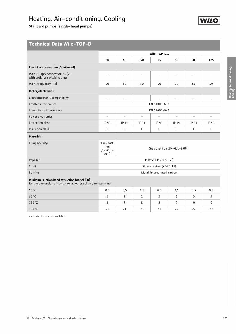
175
Heating, Air-conditioning, CoolingStandard pumps (single-head pumps)
Technical Data Wilo-TOP-D
Wilo Catalogue A1 - Circulating pumps in glandless design
Hea
tin
g, A
ir-c
on
dit
ion
ing
, C
oo
ling
Po
tab
le w
ater
cir
cula
tio
nSo
lar
ther
mal
Serv
ice/
Acc
esso
ries
, Sys
tem
sSw
itch
gea
rs a
nd
Co
ntr
ol
Dev
ices
P
um
p M
anag
emen
t S y
stem
s
Electrical connection (Continued)
Mains supply connection 3~ [V],with optional switching plug
– – – – – – –
Mains frequency [Hz] 50 50 50 50 50 50 50
Motor/electronics
Electromagnetic compatibility – – – – – – –
Emitted interference EN 61000-6-3
Immunity to interference EN 61000-6-2
Power electronics – – – – – – –
Protection class IP 44 IP 44 IP 44 IP 44 IP 44 IP 44 IP 44
Insulation class F F F F F F F
Materials
Pump housing Grey cast iron
(EN-GJL-200)
Grey cast iron (EN-GJL-250)
Impeller Plastic (PP - 50% GF)
Shaft Stainless steel (X46 Cr13)
Bearing Metal-impregnated carbon
Minimum suction head at suction branch [m]for the prevention of cavitation at water delivery temperature
50 °C 0,5 0,5 0,5 0,5 0,5 0,5 0,5
95 °C 2 2 2 2 3 3 3
110 °C 8 8 8 8 9 9 9
130 °C 21 21 21 21 22 22 22
Wilo-TOP-D...
30 40 50 65 80 100 125
• = available, – = not available
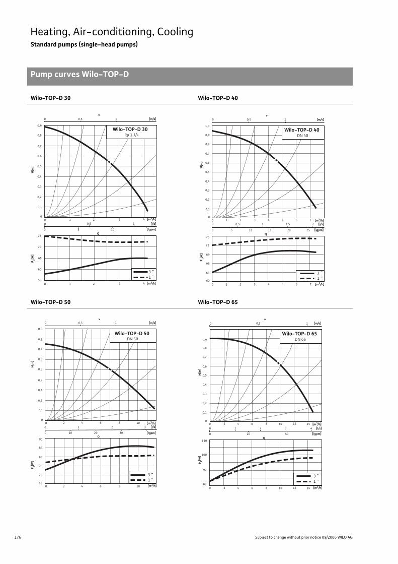
176 Subject to change without prior notice 09/2006 WILO AG
Heating, Air-conditioning, CoolingStandard pumps (single-head pumps)
Pump curves Wilo-TOP-D
Wilo-TOP-D 30 Wilo-TOP-D 40
Wilo-TOP-D 50 Wilo-TOP-D 65
0,6
0,7
0,8
0,5
0,4
0,3
0,2
0,1
0
55
60
70
65
75
0,9
0 1 2 3 40 0,5 1
0 10
0 0,5 1
5
v [m/s]
Wilo-TOP-D 30Rp 1 1/4
Q
[l/s]
[lgpm]
3 ~1 ~
0 1 2 3 4 [m3/h]
P 1[W]
H[m
]
[m3/h]
1,0
0,9
0,8
0,7
0,6
0,5
0,4
0,3
0,2
0,1
1 3 5 620
40 7
60
75
69
72
66
63
1,50,5
25155
0 0,5 1
20100
210
v [m/s]
Wilo-TOP-D 40DN 40
Q
[l/s]
[lgpm]
1 3 5 62 40 7
3 ~1 ~
[m3/h]
P 1[W]
H[m
]
[m3/h]
70
75
85
80
90
65
0 80
4 1062
0,1
0,2
0,3
0,4
0,5
0,6
0,7
0,8
0,9
0 0,5 1
0
0
1 2 3
10 20 30
v [m/s]
Wilo-TOP-D 50DN 50
Q
[l/s]
[lgpm]
0 84 1062
3 ~1 ~
[m3/h]
P 1[W]
H[m
]
[m3/h]
0,9
0,8
0,7
0,6
0,5
0,4
0,3
0,2
110
100
90
1412108642
80
0,1
00
1
0 1
0 20
0 0,5
2 3 4
40
v [m/s]
Wilo-TOP-D 65DN 65
Q
[l/s]
[lgpm]
14121086420
3 ~1 ~
[m3/h]
P 1[W]
H[m
]
[m3/h]
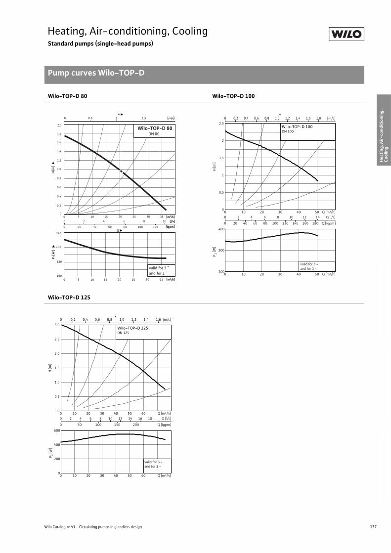
177
Heating, Air-conditioning, CoolingStandard pumps (single-head pumps)
Pump curves Wilo-TOP-D
Wilo Catalogue A1 - Circulating pumps in glandless design
Hea
tin
g, A
ir-c
on
dit
ion
ing
, C
oo
ling
Po
tab
le w
ater
cir
cula
tio
nSo
lar
ther
mal
Serv
ice/
Acc
esso
ries
, Sys
tem
sSw
itch
gea
rs a
nd
Co
ntr
ol
Dev
ices
P
um
p M
anag
emen
t S y
stem
s
Wilo-TOP-D 80 Wilo-TOP-D 100
Wilo-TOP-D 125
2,0
1,8
1,6
1,4
1,2
1,0
0,8
0,6
0,4
220
200
180
3530252015105
160
0,2
00
10 0,5v
[m/s]
Wilo-TOP-D 80DN 80
[m3/h]
P1 [
W]
H [m
]
Q
[l/s]
[lgpm]
35302520151050
valid for 3 ~and for 1 ~
806040 12020
10842
100
60
0
1,5
[m3/h]
0 [m/s]v
0
0,5
1
1,5
2
2.5
0 10 20 30 40 50 Q [m³/h]H
[m]
0 2 4 6 8 10 12 14 Q [l/s]
0 20 40 60 80 100 120 140 160 180 Q [Igpm]
300
200
400
0 10 20 30 40 50 Q [m³/h]
P 1 [W
]
0,2 0,4 0,6 0,8 1,0 1,2 1,4 1,6 1,8
Wilo-TOP-D 100DN 100
valid for 3 ~and for 1 ~
0,2 0,4 0,6v
0,8 1,0 1,2 1,4 1,60 [m/s]
0
0,5
1,0
1,5
2,0
2,5
3,0
0 10 20 30 40 50 60 Q [m³/h]
H [m
]
0 2 4 6 8 10 12 14 16 18 Q [l/s]
0 50 100 150 200 Q [Igpm]
0
200
400
600
0 10 20 30 40 50 60 Q [m³/h]
Wilo-TOP-D 125DN 125
valid for 3 ~and for 1 ~
P 1 [W
]
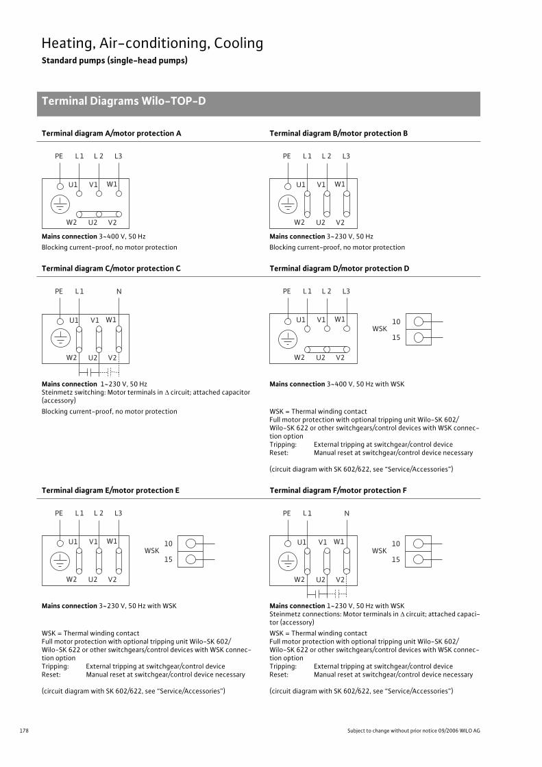
178 Subject to change without prior notice 09/2006 WILO AG
Heating, Air-conditioning, CoolingStandard pumps (single-head pumps)
Terminal Diagrams Wilo-TOP-D
Terminal diagram A/motor protection A Terminal diagram B/motor protection B
Mains connection 3~400 V, 50 Hz Mains connection 3~230 V, 50 Hz
Blocking current-proof, no motor protection Blocking current-proof, no motor protection
Terminal diagram C/motor protection C Terminal diagram D/motor protection D
Mains connection 1~230 V, 50 HzSteinmetz switching: Motor terminals in circuit; attached capacitor (accessory)
Mains connection 3~400 V, 50 Hz with WSK
Blocking current-proof, no motor protection WSK = Thermal winding contactFull motor protection with optional tripping unit Wilo-SK 602/Wilo-SK 622 or other switchgears/control devices with WSK connec-tion optionTripping: External tripping at switchgear/control deviceReset: Manual reset at switchgear/control device necessary
(circuit diagram with SK 602/622, see “Service/Accessories”)
Terminal diagram E/motor protection E Terminal diagram F/motor protection F
Mains connection 3~230 V, 50 Hz with WSK Mains connection 1~230 V, 50 Hz with WSKSteinmetz connections: Motor terminals in circuit; attached capaci-tor (accessory)
WSK = Thermal winding contactFull motor protection with optional tripping unit Wilo-SK 602/Wilo-SK 622 or other switchgears/control devices with WSK connec-tion optionTripping: External tripping at switchgear/control deviceReset: Manual reset at switchgear/control device necessary
(circuit diagram with SK 602/622, see “Service/Accessories”)
L 1 L3PE
W2 U2 V2
U1 V1 W1
L 2 L 1 L3PE
W2 U2 V2
U1 V1 W1
L 2
L 1 NPE
W2 U2 V2
U1 V1 W1
L 1 L3PE
W2 U2 V2
U1 V1 W1
L 2
10
15WSK
L 1 L3PE
W2 U2 V2
U1 V1 W1
L 2
10
15WSK
L 1 NPE
W2 U2 V2
U1 V1 W1 10
15WSK
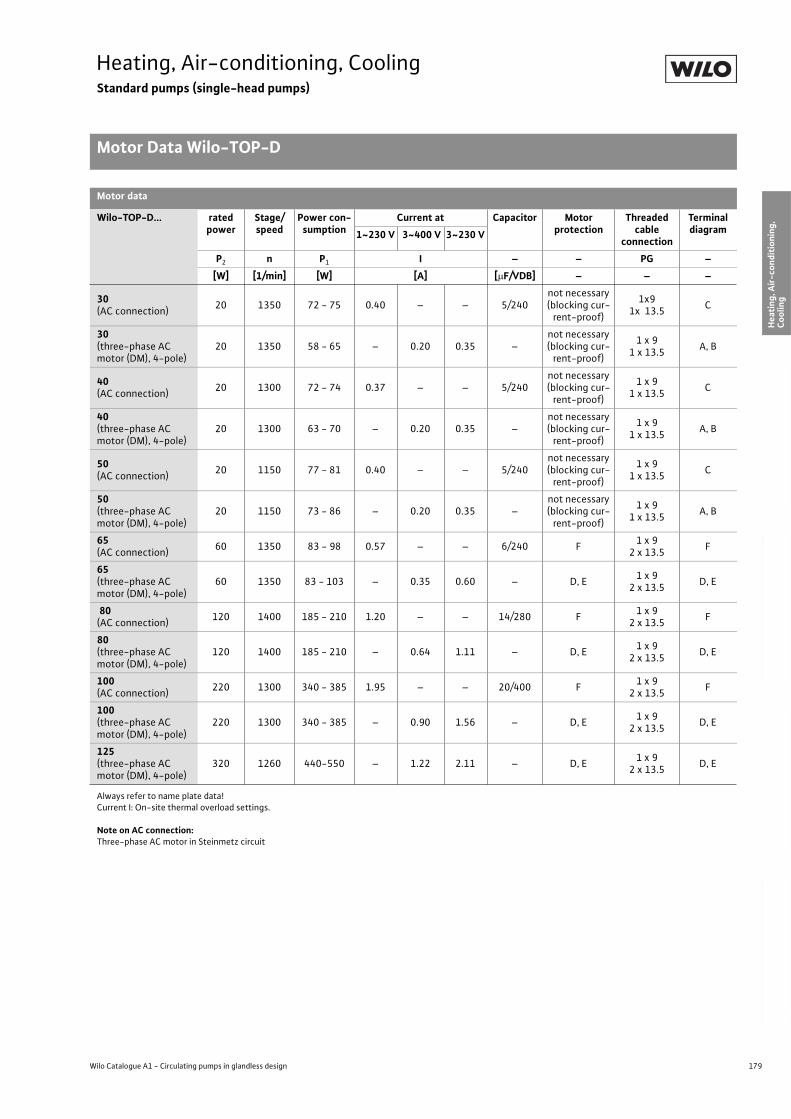
179
Heating, Air-conditioning, CoolingStandard pumps (single-head pumps)
Motor Data Wilo-TOP-D
Wilo Catalogue A1 - Circulating pumps in glandless design
Hea
tin
g, A
ir-c
on
dit
ion
ing
, C
oo
ling
Po
tab
le w
ater
cir
cula
tio
nSo
lar
ther
mal
Serv
ice/
Acc
esso
ries
, Sys
tem
sSw
itch
gea
rs a
nd
Co
ntr
ol
Dev
ices
P
um
p M
anag
emen
t S y
stem
s
Motor data
Wilo-TOP-D... rated power
Stage/speed
Power con-sumption
Current at Capacitor Motor protection
Threaded cable
connection
Terminal diagram1~230 V 3~400 V 3~230 V
P2 n P1 I – – PG –
[W] [1/min] [W] [A] [ F/VDB] – – –
30(AC connection)
20 1350 72 - 75 0.40 – – 5/240not necessary (blocking cur-
rent-proof)
1x91x 13.5
C
30(three-phase AC motor (DM), 4-pole)
20 1350 58 - 65 – 0.20 0.35 –not necessary (blocking cur-
rent-proof)
1 x 91 x 13.5
A, B
40(AC connection)
20 1300 72 - 74 0.37 – – 5/240not necessary (blocking cur-
rent-proof)
1 x 91 x 13.5
C
40(three-phase AC motor (DM), 4-pole)
20 1300 63 - 70 – 0.20 0.35 –not necessary (blocking cur-
rent-proof)
1 x 91 x 13.5
A, B
50(AC connection)
20 1150 77 - 81 0.40 – – 5/240not necessary (blocking cur-
rent-proof)
1 x 91 x 13.5
C
50(three-phase AC motor (DM), 4-pole)
20 1150 73 - 86 – 0.20 0.35 –not necessary (blocking cur-
rent-proof)
1 x 91 x 13.5
A, B
65(AC connection)
60 1350 83 - 98 0.57 – – 6/240 F1 x 9
2 x 13.5F
65(three-phase AC motor (DM), 4-pole)
60 1350 83 - 103 – 0.35 0.60 – D, E1 x 9
2 x 13.5D, E
80(AC connection)
120 1400 185 - 210 1.20 – – 14/280 F1 x 9
2 x 13.5F
80(three-phase AC motor (DM), 4-pole)
120 1400 185 - 210 – 0.64 1.11 – D, E1 x 9
2 x 13.5D, E
100(AC connection)
220 1300 340 - 385 1.95 – – 20/400 F1 x 9
2 x 13.5F
100(three-phase AC motor (DM), 4-pole)
220 1300 340 - 385 – 0.90 1.56 – D, E1 x 9
2 x 13.5D, E
125(three-phase AC motor (DM), 4-pole)
320 1260 440-550 – 1.22 2.11 – D, E1 x 9
2 x 13.5D, E
Always refer to name plate data! Current I: On-site thermal overload settings.
Note on AC connection:Three-phase AC motor in Steinmetz circuit
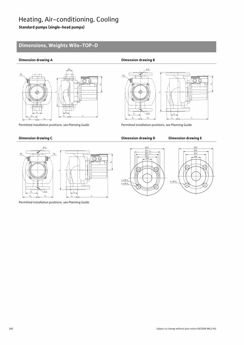
180 Subject to change without prior notice 09/2006 WILO AG
Heating, Air-conditioning, CoolingStandard pumps (single-head pumps)
Dimensions, Weights Wilo-TOP-D
Dimension drawing A Dimension drawing B
Permitted installation positions, see Planning Guide Permitted installation positions, see Planning Guide
Dimension drawing C Dimension drawing D Dimension drawing E
Permitted installation positions, see Planning Guide
Pg
Rp
b1
b2 b2
G
l 0
b 3
a2
a1
l1
Pg
l 0
b 3
b1
b2 b2
R 1/8
R 1/8
a1
l1a2
PgPg
l 0
b 3
b1
b2 b2
R 1/8
R 1/8
a1
l1a2
Ø D
n x Ø d
Ø k
DN
L2
Ø k Ø d
L 1
1
n x Ø d 2
n x Ø d
Ø D Ø k
DN
Ø d
L
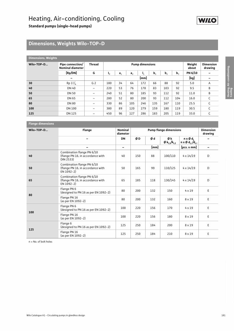
181
Heating, Air-conditioning, CoolingStandard pumps (single-head pumps)
Dimensions, Weights Wilo-TOP-D
Wilo Catalogue A1 - Circulating pumps in glandless design
Hea
tin
g, A
ir-c
on
dit
ion
ing
, C
oo
ling
Po
tab
le w
ater
cir
cula
tio
nSo
lar
ther
mal
Serv
ice/
Acc
esso
ries
, Sys
tem
sSw
itch
gea
rs a
nd
Co
ntr
ol
Dev
ices
P
um
p M
anag
emen
t S y
stem
s
Dimensions, Weights
Wilo-TOP-D... Pipe connection/Nominal diameter
Thread Pump dimensions Weight about
Dimension drawing
[Rp/DN] G I0 a1 a2 l1 b1 b2 b3 PN 6/10 –
– [mm] [kg] –
30 Rp 11/4 G 2 180 34 64 172 66 88 92 5.0 A
40 DN 40 – 220 53 76 178 83 103 92 9.5 B
50 DN 50 – 240 51 80 185 93 112 92 11.0 B
65 DN 65 – 280 52 80 200 93 112 104 16.0 C
80 DN 80 – 330 86 105 246 135 167 110 25.5 C
100 DN 100 – 380 89 120 279 159 180 119 30.5 C
125 DN 125 – 450 96 127 286 183 205 119 33.0 C
Flange dimensions
Wilo-TOP-D... Flange Nominal diameter
Pump flange dimensions Dimension drawing
– DN Ø D Ø d Ø kØ kL1/kL2
n x Ø dLn x Ø dL1/dL2
–
– – [mm] [pcs. x mm] –
40Combination flange PN 6/10(flange PN 16, in accordance with DIN 2533)
40 150 88 100/110 4 x 14/19 D
50Combination flange PN 6/10(flange PN 16, in accordance with EN 1092-2)
50 165 99 110/125 4 x 14/19 D
65Combination flange PN 6/10(flange PN 16, in accordance with EN 1092-2)
65 185 118 130/145 4 x 14/19 D
80
Flange PN 6(designed to PN 16 as per EN 1092-2)
80 200 132 150 4 x 19 E
Flange PN 16 (as per EN 1092-2)
80 200 132 160 8 x 19 E
100
Flange PN 6(designed to PN 16 as per EN 1092-2)
100 220 156 170 4 x 19 E
Flange PN 16 (as per EN 1092-2)
100 220 156 180 8 x 19 E
125
Flange 6(designed to PN 16 as per EN 1092-2)
125 250 184 200 8 x 19 E
Flange PN 16 (as per EN 1092-2)
125 250 184 210 8 x 19 E
n = No. of bolt holes
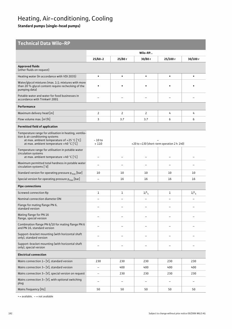
182 Subject to change without prior notice 09/2006 WILO AG
Heating, Air-conditioning, CoolingStandard pumps (single-head pumps)
Technical Data Wilo-RP
Wilo-RP...
25/60-2 25/80 r 30/80 r 25/100 r 30/100 r
Approved fluids(other fluids on request)
Heating water (In accordance with VDI 2035) • • • • •
Water/glycol mixtures (max. 1:1; mixtures with more than 20 % glycol content require rechecking of the pumping data)
• • • • •
Potable water and water for food businesses in accordance with TrinkwV 2001
– – – – –
Performance
Maximum delivery head [m] 2 2 2 4 4
Flow volume max. [m3/h] 3 3.7 3.7 6 6
Permitted field of application
Temperature range for utilisation in heating, ventila-tion & air conditioning systems
at max. ambient temperature of +25 °C [°C]at max. ambient temperature +40 °C [°C]
- 10 to + 110
–+20 to +130 (short-term operation 2 h: 140)
Temperature range for utilisation in potable water circulation systems
at max. ambient temperature +40 °C [°C] – – – – –
Maximum permitted total hardness in potable water circulation systems [°d]
– – – – –
Standard version for operating pressure pmax [bar] 10 10 10 10 10
Special version for operating pressure pmax [bar] – 16 16 16 16
Pipe connections
Screwed connection Rp 1 1 1/14 1 1/1
4
Nominal connection diameter DN – – – – –
Flange for mating flange PN 6, standard version
– – – – –
Mating flange for PN 16 flange, special version
– – – – –
Combination flange PN 6/10 for mating flange PN 6 and PN 16, standard version
– – – – –
Support-bracket mounting (with horizontal shaft only), standard version
– – – – –
Support-bracket mounting (with horizontal shaft only), special version
– – – – –
Electrical connection
Mains connection 1~ [V], standard version 230 230 230 230 230
Mains connection 3~ [V], standard version – 400 400 400 400
Mains connection 3~ [V], special version on request – 230 230 230 230
Mains connection 3~ [V], with optional switching plug
– – – – –
Mains frequency [Hz] 50 50 50 50 50
• = available, – = not available

183
Heating, Air-conditioning, CoolingStandard pumps (single-head pumps)
Technical Data Wilo-RP
Wilo Catalogue A1 - Circulating pumps in glandless design
Hea
tin
g, A
ir-c
on
dit
ion
ing
, C
oo
ling
Po
tab
le w
ater
cir
cula
tio
nSo
lar
ther
mal
Serv
ice/
Acc
esso
ries
, Sys
tem
sSw
itch
gea
rs a
nd
Co
ntr
ol
Dev
ices
P
um
p M
anag
emen
t S y
stem
s
Motor/electronics
Electromagnetic compatibility – – – – –
Emitted interference EN 61000-6-3
Immunity to interference EN 61000-6-2
Power electronics – – – – –
Protection class IP 44 IP 42 IP 42 IP 42 IP 42
Insulation class F F F F F
Materials
Pump housing Grey cast iron (EN-GJL-200)
Impeller Plastic (PP - 50% GF)
Shaft Stainless steel (X46 Cr13)
Bearing Metal-impregnated carbon
Minimum suction head at suction branch [m]for the prevention of cavitation at water delivery temperature
50 °C 0.5 0.5 0.5 0.5 0.5
95 °C 1.5 2 2 2 2
110 °C 8 8 8 8 8
130 °C – 21 21 21 21
Wilo-RP...
25/60-2 25/80 r 30/80 r 25/100 r 30/100 r
• = available, – = not available
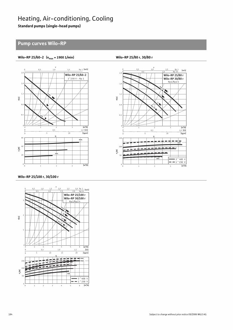
184 Subject to change without prior notice 09/2006 WILO AG
Heating, Air-conditioning, CoolingStandard pumps (single-head pumps)
Pump curves Wilo-RP
Wilo-RP 25/60-2 (nmax = 1900 1/min) Wilo-RP 25/80 r, 30/80 r
Wilo-RP 25/100 r, 30/100 r
Q
0,50
00
0
0
1
[l/s]
[lgpm]
00
Wilo-RP 25/60-21~230 V - Rp 1
2
0,5
1 2
3
3
[m/s]
0,4
0,8
1,2
1,6
2,0
v1,0 1,5
1,0
105
60
40
20
Rp
max.
min.
max.
min.
1
[m3/h]
P 1[W]
H[m
]
[m3/h]
Q
0,50
00
0
0
1
[l/s]
[lgpm]
00
2
0,5
1 2
3
3
[m/s]
0,4
0,8
1,2
1,6
2,00,5
v
0
1,0
1,0
1,5
1,0
105
(2 )
(3 )
150
100
50
min.
Rp 1Rp 1¼
3 ~ 400 V1 ~ 230 V
max.
max.(1 )
min.(4 )
Wilo-RP 25/80 r Wilo-RP 30/80 r
Rp1/Rp1¼
[m3/h]
P 1[W]
H[m
]
[m3/h]
100
max.
min.
150
50min.
max.
Q
0,50
00
0
0
1
[l/s]
[lgpm]
00
Wilo-RP 25/100 r Wilo-RP 30/100 r
Rp1/Rp1¼
2
0,5
3
[m/s]
1
2
3
0,5
v
0
1,0
1,0
1,5
1,0
105
min.(4 )
Rp 1
Rp 1¼
4 5 6
2,0 2,5 3,0
1,5 2,0
15
1,5
20
1 2 3 4 5 6
3 ~ 400 V1 ~ 230 V
max.(1 )(2 )
(3 )
[m3/h]
P 1[W]
H[m
]
[m3/h]
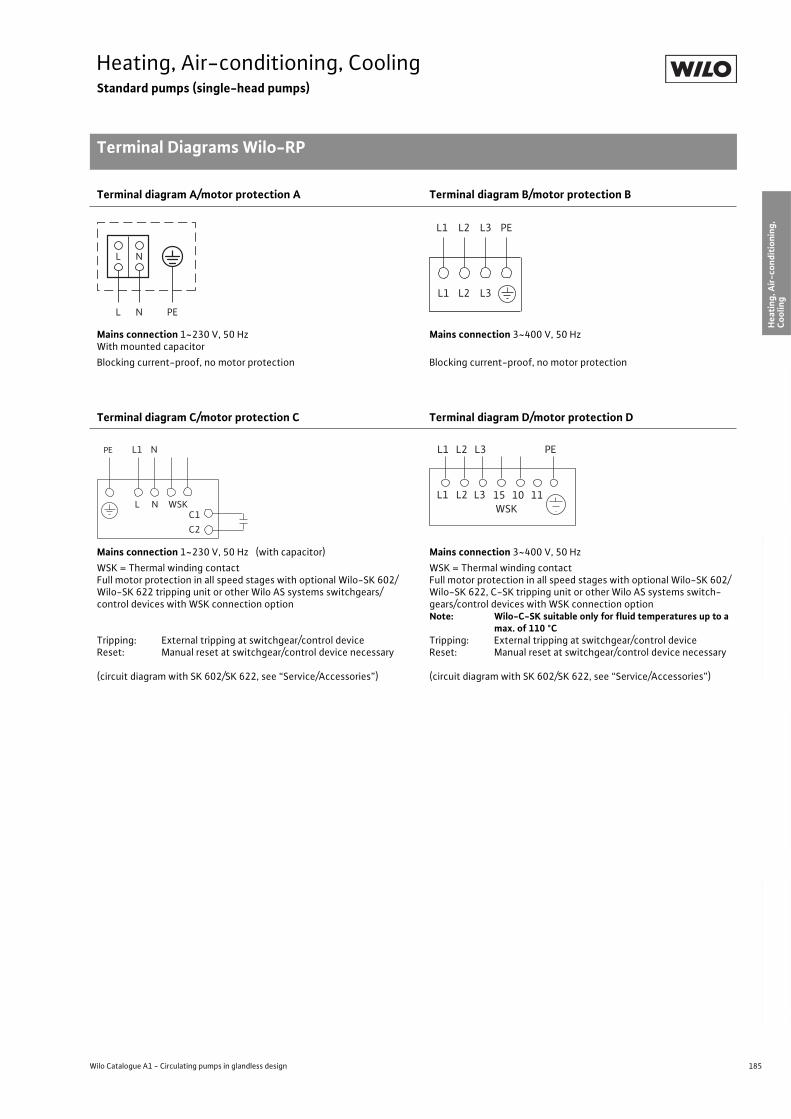
185
Heating, Air-conditioning, CoolingStandard pumps (single-head pumps)
Terminal Diagrams Wilo-RP
Wilo Catalogue A1 - Circulating pumps in glandless design
Hea
tin
g, A
ir-c
on
dit
ion
ing
, C
oo
ling
Po
tab
le w
ater
cir
cula
tio
nSo
lar
ther
mal
Serv
ice/
Acc
esso
ries
, Sys
tem
sSw
itch
gea
rs a
nd
Co
ntr
ol
Dev
ices
P
um
p M
anag
emen
t S y
stem
s
Terminal diagram A/motor protection A Terminal diagram B/motor protection B
Mains connection 1~230 V, 50 HzWith mounted capacitor
Mains connection 3~400 V, 50 Hz
Blocking current-proof, no motor protection Blocking current-proof, no motor protection
Terminal diagram C/motor protection C Terminal diagram D/motor protection D
Mains connection 1~230 V, 50 Hz (with capacitor) Mains connection 3~400 V, 50 Hz
WSK = Thermal winding contactFull motor protection in all speed stages with optional Wilo-SK 602/Wilo-SK 622 tripping unit or other Wilo AS systems switchgears/control devices with WSK connection option
Tripping: External tripping at switchgear/control deviceReset: Manual reset at switchgear/control device necessary
(circuit diagram with SK 602/SK 622, see “Service/Accessories”)
WSK = Thermal winding contactFull motor protection in all speed stages with optional Wilo-SK 602/Wilo-SK 622, C-SK tripping unit or other Wilo AS systems switch-gears/control devices with WSK connection optionNote: Wilo-C-SK suitable only for fluid temperatures up to a
max. of 110 °CTripping: External tripping at switchgear/control deviceReset: Manual reset at switchgear/control device necessary
(circuit diagram with SK 602/SK 622, see “Service/Accessories”)
L N
L N
PE
L1 L2 L3
L1 L2 L3
PE
L
PE L1 N
N WSKC1
C2
L1WSK
L2 L3 15 10 11
PEL1 L2 L3
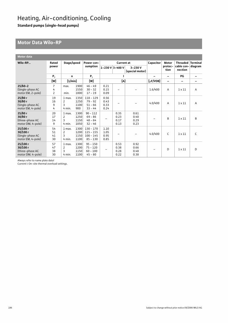
186 Subject to change without prior notice 09/2006 WILO AG
Heating, Air-conditioning, CoolingStandard pumps (single-head pumps)
Motor Data Wilo-RP
Motor data
Wilo-RP... Rated power
Stage/speed Power con-sumption
Current at Capacitor Motor protec-
tion
Threaded cable con-
nection
Terminal diagram1~230 V 3~400 V 3~230 V
(special motor)
P2 n P1 I – – PG –
[W] [1/min] [W] [A] [ F/VDB] – – –
25/60-2(Single-phase AC motor EM, 2-pole)
742
max. 1900 1550
min. 1000
46 - 4930 - 3217 - 19
0.210.150.09
– – 1.6/400 A 1 x 11 A
25/80 r 30/80 r(Single-phase AC motor EM, 4-pole)
191694
1 max. 1350 2 12503 11004 min. 900
118 - 12979 - 9251 - 6633 - 44
0.560.430.330.24
– – 4.0/400 A 1 x 11 A
25/80 r 30/80 r(three-phase AC motor DM, 4-pole)
2017149
1 max. 1300 2 12503 11504 min. 1050
90 - 11269 - 8648 - 6432 - 46
–
0.350.230.170.13
0.610.400.290.23
– B 1 x 11 B
25/100 r 30/100 r(Single-phase AC motor EM, 4-pole)
54514130
1 max. 1300 2 12003 11504 min. 1100
130 - 170115 - 155100 - 145 85 - 130
1.101.050.950.85
– – 4.0/400 C 1 x 11 C
25/100 r 30/100 r(three-phase AC motor DM, 4-pole)
57473830
1 max. 1300 2 12003 11504 min. 1100
95 - 150 75 - 120 60 - 10045 - 80
–
0.530.380.280.22
0.920.660.480.38
– D 1 x 11 D
Always refer to name plate data!Current I: On-site thermal overload settings.
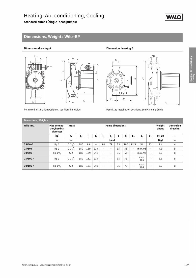
187
Heating, Air-conditioning, CoolingStandard pumps (single-head pumps)
Dimensions, Weights Wilo-RP
Wilo Catalogue A1 - Circulating pumps in glandless design
Hea
tin
g, A
ir-c
on
dit
ion
ing
, C
oo
ling
Po
tab
le w
ater
cir
cula
tio
nSo
lar
ther
mal
Serv
ice/
Acc
esso
ries
, Sys
tem
sSw
itch
gea
rs a
nd
Co
ntr
ol
Dev
ices
P
um
p M
anag
emen
t S y
stem
s
Dimension drawing A Dimension drawing B
Permitted installation positions, see Planning Guide Permitted installation positions, see Planning Guide
Dimensions, Weights
Wilo-RP... Pipe connec-tion/nominal
diameter
Thread Pump dimensions Weight about
Dimension drawing
[Rp] G I0 l1 l2 l3 l4 a b1 b2 b3 b4 PN 10 –
– – [mm] [kg] –
25/60-2 Rp 1 G 11/2 180 93 – 90 79 35 100 92,5 54 73 2.4 A
25/80 r Rp 1 G 11/2 180 169 234 – – 35 58 – max. 98 – 4.5 B
30/80 r Rp 11/4 G 2 180 169 244 – – 35 58 – max. 98 – 4.5 B
25/100 r Rp 1 G 11/2 180 181 234 – – 35 75 –max.106
– 6.5 B
30/100 r Rp 11/4 G 2 180 181 244 – – 35 75 –max.106
– 6.5 B
b2
b1
b4
l 0
l1
l4
l 3
G
PG 11
b3
a
G
DN
b1 b3
l1a
l0 l2
Pg 11
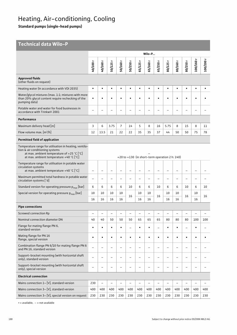
188 Subject to change without prior notice 09/2006 WILO AG
Heating, Air-conditioning, CoolingStandard pumps (single-head pumps)
Technical data Wilo-P
Wilo-P...
40
/10
0 r
40
/16
0 r
50
/12
5 r
50
/16
0 r
50
/25
0 r
65
/12
5 r
65
/16
0 r
65
/25
0 r
80
/12
5 r
80
/16
0 r
80
/25
0 r
10
0/1
60
r
10
0/2
00
r
Approved fluids(other fluids on request)
Heating water (In accordance with VDI 2035) • • • • • • • • • • • • •
Water/glycol mixtures (max. 1:1; mixtures with more than 20% glycol content require rechecking of the pumping data)
• • • • • • • • • • • • •
Potable water and water for food businesses in accordance with TrinkwV 2001
– – – – – – – – – – – – –
Performance
Maximum delivery head [m] 3 6 3.75 7 14 5 8 16 5.75 8 15 8 11
Flow volume max. [m3/h] 12 13.5 21 22 22 35 35 37 44 50 50 75 78
Permitted field of application
Temperature range for utilisation in heating, ventila-tion & air conditioning systems
at max. ambient temperature of +25 °C [°C]at max. ambient temperature +40 °C [°C]
–+20 to +130 (in short-term operation 2 h: 140)
Temperature range for utilisation in potable water circulation systems
at max. ambient temperature +40 °C [°C] – – – – – – – – – – – – –
Maximum permitted total hardness in potable water circulation systems [°d]
– – – – – – – – – – – – –
Standard version for operating pressure pmax [bar] 6 6 6 6 10 6 6 10 6 6 10 6 10
Special version for operating pressure pmax [bar] 10 10 10 1016
10 1016
10 1016
1016
16 16 16 16 16 16 16 16 16
Pipe connections
Screwed connection Rp – – – – – – – – – – – – –
Nominal connection diameter DN 40 40 50 50 50 65 65 65 80 80 80 100 100
Flange for mating flange PN 6, standard version
• • • • – • • – • • – • –
Mating flange for PN 16 flange, special version
• • • • • • • • • • • • •
Combination flange PN 6/10 for mating flange PN 6 and PN 16, standard version
– – – – – – – – – – – – –
Support-bracket mounting (with horizontal shaft only), standard version
– – – – – – – – – – – – –
Support-bracket mounting (with horizontal shaft only), special version
– – – – – – – – – – – – –
Electrical connection
Mains connection 1~ [V], standard version 230 – – – – – – – – – – – –
Mains connection 3~ [V], standard version 400 400 400 400 400 400 400 400 400 400 400 400 400
Mains connection 3~ [V], special version on request 230 230 230 230 230 230 230 230 230 230 230 230 230
• = available, – = not available
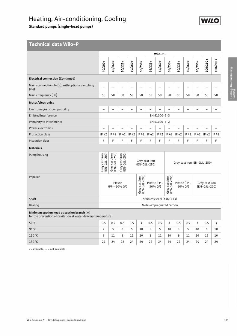
189
Heating, Air-conditioning, CoolingStandard pumps (single-head pumps)
Technical data Wilo-P
Wilo Catalogue A1 - Circulating pumps in glandless design
Hea
tin
g, A
ir-c
on
dit
ion
ing
, C
oo
ling
Po
tab
le w
ater
cir
cula
tio
nSo
lar
ther
mal
Serv
ice/
Acc
esso
ries
, Sys
tem
sSw
itch
gea
rs a
nd
Co
ntr
ol
Dev
ices
P
um
p M
anag
emen
t S y
stem
s
Electrical connection (Continued)
Mains connection 3~ [V], with optional switching plug
– – – – – – – – – – – – –
Mains frequency [Hz] 50 50 50 50 50 50 50 50 50 50 50 50 50
Motor/electronics
Electromagnetic compatibility – – – – – – – – – – – – –
Emitted interference EN 61000-6-3
Immunity to interference EN 61000-6-2
Power electronics – – – – – – – – – – – – –
Protection class IP 42 IP 42 IP 42 IP 42 IP 42 IP 42 IP 42 IP 42 IP 42 IP 42 IP 42 IP 42 IP 42
Insulation class F F F F F F F F F F F F F
Materials
Pump housing
Gre
y ca
st ir
on
(E
N-G
JL-2
00
)
Gre
y ca
st ir
on
(E
N-G
JL-2
50
)
Gre
y ca
st ir
on
(E
N-G
JL-2
00
)
Grey cast iron (EN-GJL-250)
Grey cast iron (EN-GJL-250)
Impeller
Plastic(PP - 50% GF)
Gre
y ca
st ir
on
(EN
-GJL
-20
0)
Plastic (PP - 50% GF)
Gre
y ca
st ir
on
(EN
-GJL
-20
0)
Plastic (PP - 50% GF)
Grey cast iron (EN-GJL-200)
Shaft Stainless steel (X46 Cr13)
Bearing Metal-impregnated carbon
Minimum suction head at suction branch [m]for the prevention of cavitation at water delivery temperature
50 °C 0.5 0.5 0.5 0.5 3 0.5 0.5 3 0.5 0.5 3 0.5 3
95 °C 2 5 3 5 10 3 5 10 3 5 10 5 10
110 °C 8 11 9 11 16 9 11 16 9 11 16 11 16
130 °C 21 24 22 24 29 22 24 29 22 24 29 24 29
Wilo-P...
40
/10
0 r
40
/16
0 r
50
/12
5 r
50
/16
0 r
50
/25
0 r
65
/12
5 r
65
/16
0 r
65
/25
0 r
80
/12
5 r
80
/16
0 r
80
/25
0 r
10
0/1
60
r
10
0/2
00
r
• = available, – = not available
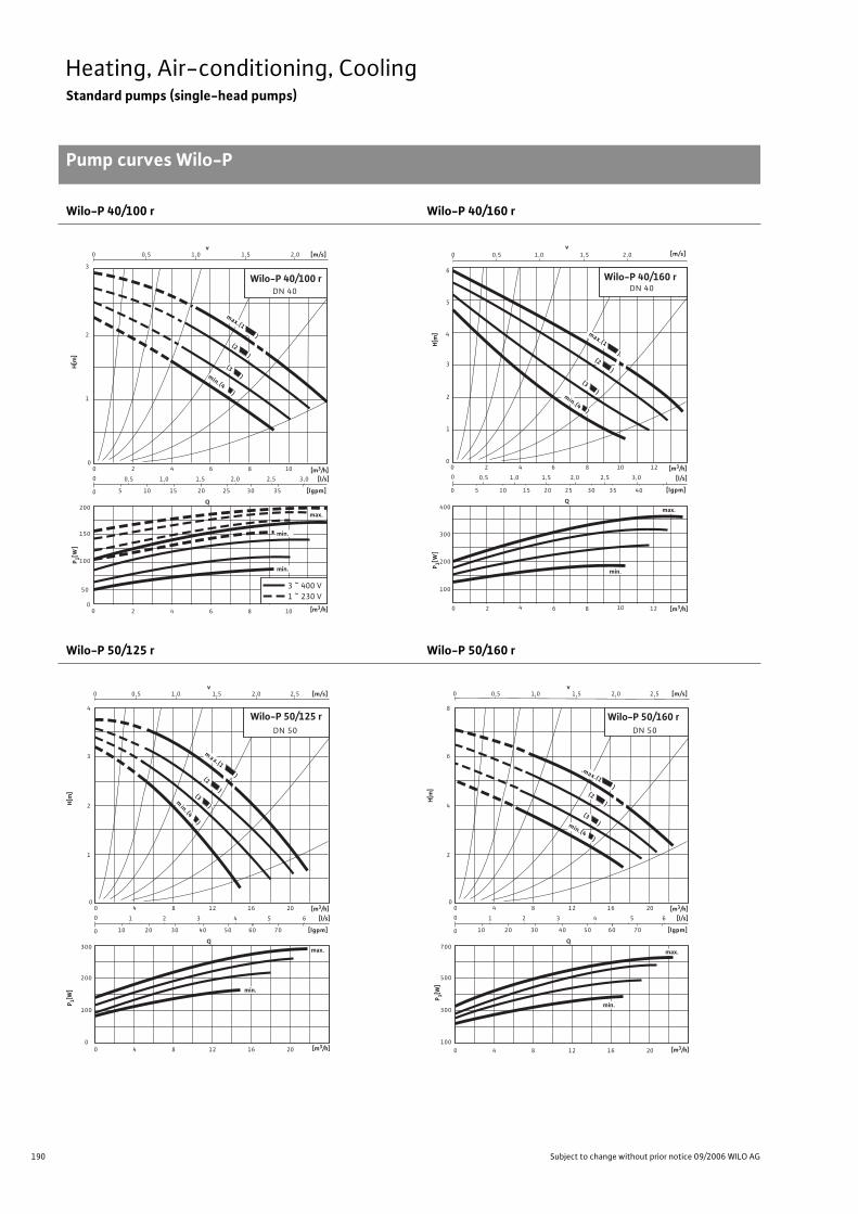
190 Subject to change without prior notice 09/2006 WILO AG
Heating, Air-conditioning, CoolingStandard pumps (single-head pumps)
Pump curves Wilo-P
Wilo-P 40/100 r Wilo-P 40/160 r
Wilo-P 50/125 r Wilo-P 50/160 r
Q
0,50
00
0
0
[l/s]
[lgpm]
00
DN 40
2
0,5
[m/s]
1
2
3
v1,0 1,5
1,0
105
max.(1 )(2
)
(3 )min.(4 )
200
150
50
4 106
2,0
15
1,5
20
100
max.
min.
8
2,0 2,5 3,0
25 30 35
3 ~ 400 V1 ~ 230 V
2 4 106 8
min.
[m3/h]
P 1[W]
H[m
]
[m3/h]
Wilo-P 40/100 r
Q
0,50
00
0
0
[l/s]
[lgpm]
0
Wilo-P 40/160 r DN 40
2
0,5
[m/s]
1
4
6
v1,0 1,5
1,0
105
(2 )
(3 )
400
300
100
4 10
4 10
6
2,0
15
1,5
20
200
max.
min.
8
2,0 2,5 3,0
25 30 35
5
3
2
12
min.(4 )
max.(1 )
40
2 6 8 12
[m3/h]
[m3/h]
P 1[W]
H[m
]
Q
0,50
00
0
0
[l/s]
[lgpm]
DN 50
4
1
[m/s]
1
2
3
v 1,0 1,5
2
2010
300
200
8 2012
2,0
30
3
40
0
max.
16
0 4 8 2012 16
4 5 6
50 60
4
2,5
70
100
min.(4 )
(3 )
(2 )
m ax.(1 )
min.
Wilo-P 50/125 r
[m3/h]
P 1[W]
H[m
]
[m3/h]
Q
0,50
00
0
0
[l/s]
[lgpm]
Wilo-P 50/160 r DN 50
4
1
[m/s]
2
4
6
v 1,0 1,5
2
2010
700
500
8 2012
2,0
30
3
40
100
max.
16
0 4 8 2012 16
4 5 6
50 60
8
2,5
70
300
min.(4 )
(3 )
(2 )
.max.(1 )
min.
[m3/h]
P 1[W]
H[m
]
[m3/h]
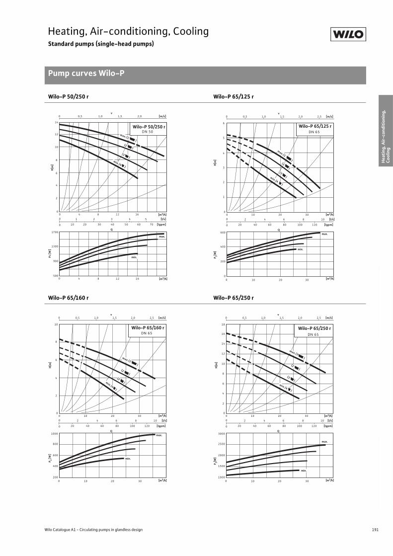
191
Heating, Air-conditioning, CoolingStandard pumps (single-head pumps)
Pump curves Wilo-P
Wilo Catalogue A1 - Circulating pumps in glandless design
Hea
tin
g, A
ir-c
on
dit
ion
ing
, C
oo
ling
Po
tab
le w
ater
cir
cula
tio
nSo
lar
ther
mal
Serv
ice/
Acc
esso
ries
, Sys
tem
sSw
itch
gea
rs a
nd
Co
ntr
ol
Dev
ices
P
um
p M
anag
emen
t S y
stem
s
Wilo-P 50/250 r Wilo-P 65/125 r
Wilo-P 65/160 r Wilo-P 65/250 r
Q
0,50
00
0
0
[l/s]
[lgpm]
0
Wilo-P 50/250 r DN 50
1
[m/s]
2
4
6
v1,0 1,5
2
2010
1700
1300
8 12
2,0
30
3
40
500
max.
16
4 5
50 60
4 8 12 16
8
70
900
10
12
14
4
(2 )
(3)
max.(1)
min.(4)
min.
[m3/h]
P1 [
W]
H[m
]
[m3/h]
Q
0,50
00
0
0
[l/s]
[lgpm]
0
DN 65
2
[m/s]
1
2
3
v1,0 1,5
4
20
600
400
3020
2,0
6
40
0
max.
8
60
3010 20
80
200
4
5
6
10
min.
2,5
min.(4 )
(3)
(2)
max.(1 )
10
100 120
Wilo-P 65/125 r
P 1[W]
H[m
] [m3/h]
[m3/h]
Q
0,50
00
0
0
[l/s]
[lgpm]
0
DN 65
2
[m/s]
2
4
v1,0 1,5
4
20
1000
800
3020
2,0
6
40
200
max.
8
60
10 20
80
600
6
8
10
10
2,5
min.(4)
10
100 120
(3)
(2 )
max.(1 )
400
30
min.
Wilo-P 65/160 r
[m3/h]
P 1 [W
]H
[m]
[m3/h]
Q
0,50
00
0
0
[l/s]
[lgpm]
0
Wilo-P 65/250 r DN 65
2
[m/s]
4
6
v1,0 1,5
4
20
3000
2500
3020
2,0
6
40
1000
8
60
10 20
80
2000
10
14
18
10
2,5
10
100 120
(3)
(2 )
1500
30
min.
16
12
8
2
max.(1 )
min.(4 )
max.
[m3/h]
P 1[W]
H[m
]
[m3/h]
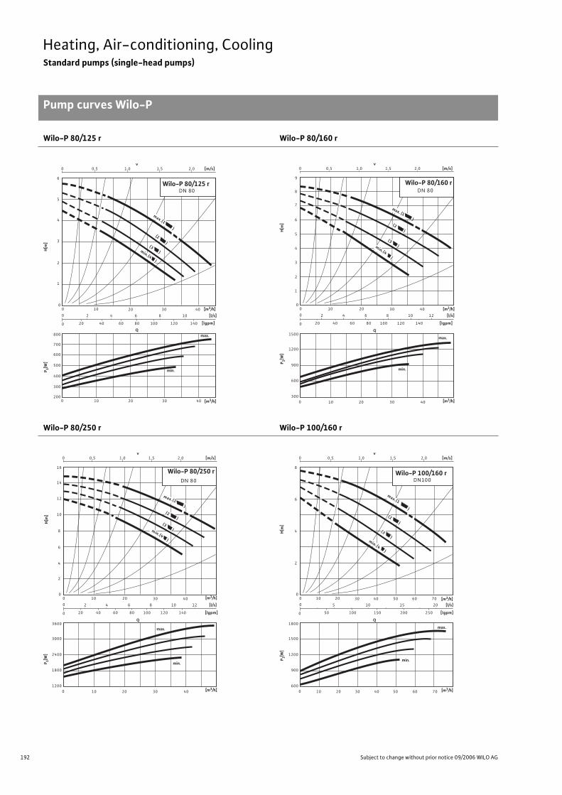
192 Subject to change without prior notice 09/2006 WILO AG
Heating, Air-conditioning, CoolingStandard pumps (single-head pumps)
Pump curves Wilo-P
Wilo-P 80/125 r Wilo-P 80/160 r
Wilo-P 80/250 r Wilo-P 100/160 r
max.Q
0,50
00
0
0
[l/s]
[lgpm]
0
Wilo-P 80/125 rDN 80
2
[m/s]
2
v 1,0 1,5
4
20
800
700
3020
2,0
6
40
200
8
60
10 20
80
600
6
10
10
100 120
(3 )
500
30
min.
5
4
3
1
max.(1 )
(2 )
min.(4 )
140
400
300
40
40 [m3/h]
P 1[W]
H[m
]
[m3/h]
Q
0,50
00
0
0
[l/s]
[lgpm]
0
DN 80
2
[m/s]
3
v 1,0 1,5
4
20
1500
1200
3020
2,0
6
40
8
60
10 20
80
9
10
10
100 120
(3 )
900
30
6
5
1
max.
max. (1 )(2 )
140
600
30040
8
7
4
2
min.(4 )
40
12
min.
Wilo-P 80/160 r
[m3/h]
P 1[W]
H[m
]
[m3/h]
Q
0,50
00
0
0
[l/s]
[lgpm]
0
DN 80
2
[m/s]
6
v1,0 1,5
4
20
3600
3000
3020
2,0
6
40
8
60
10 20
80
16
10
10
100 120
2400
30
10
8
2
max.
140
1800
120040
14
12
4
40
12
min.
max.(1 )(2 )
(3 )min.(4 )
Wilo-P 80/250 r
[m3/h]
P 1[W]
H[m
]
[m3/h]
Q
0,50
00
0
0
[l/s]
[lgpm]
0
Wilo-P 100/160 rDN100
[m/s]
6
v1,0 1,5
5
1800
1500
3020
2,0
10 20 7030 40
50
10
10
100
1200
50 60
8
2
max.
200
900
600
4
40
min.
(3 )
50 60 70
min.(4 )
(2 )
max.(1 )
15 20
150 250
[m3/h]
P 1[W]
H[m
]
[m3/h]
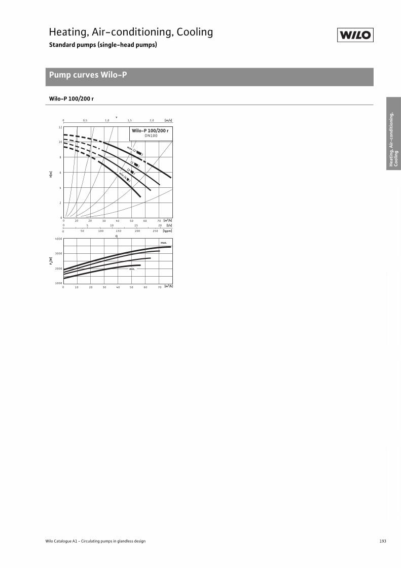
193
Heating, Air-conditioning, CoolingStandard pumps (single-head pumps)
Pump curves Wilo-P
Wilo Catalogue A1 - Circulating pumps in glandless design
Hea
tin
g, A
ir-c
on
dit
ion
ing
, C
oo
ling
Po
tab
le w
ater
cir
cula
tio
nSo
lar
ther
mal
Serv
ice/
Acc
esso
ries
, Sys
tem
sSw
itch
gea
rs a
nd
Co
ntr
ol
Dev
ices
P
um
p M
anag
emen
t S y
stem
s
Wilo-P 100/200 r
Q
0,50
00
0
0
[l/s]
[lgpm]
0
Wilo-P 100/200 rDN100
[m/s]
8
v 1,0 1,5
5
4000
3000
3020
2,0
10 20 7030 40
50
10
10
100
2000
50 60
12
200
1000
6
40 50 60 70
(2 )
15 20
150 250
max.(1 )
(3 )min.(4 )
10
4
2
min.
max.
[m3/h]
P 1[W]
H[m
]
[m3/h]
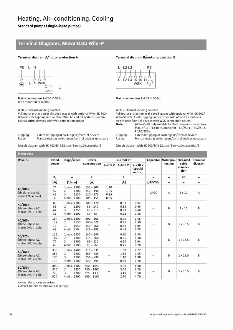
194 Subject to change without prior notice 09/2006 WILO AG
Heating, Air-conditioning, CoolingStandard pumps (single-head pumps)
Terminal Diagrams, Motor Data Wilo-P
Terminal diagram A/motor protection A Terminal diagram B/motor protection B
Mains connection 1~230 V, 50 HzWith mounted capacitor
Mains connection 3~400 V, 50 Hz
WSK = Thermal winding contactFull motor protection in all speed stages with optional Wilo-SK 602/Wilo-SK 622 tripping unit or other Wilo AS and CR systems switch-gears/control devices with WSK connection option
Tripping: External tripping at switchgears/control devicesReset: Manual reset at switchgears/control devices necessary
(circuit diagram with SK 602/SK 622, see “Service/Accessories”)
WSK = Thermal winding contactFull motor protection in all speed stages with optional Wilo-SK 602/Wilo-SK 622, C-SK tripping unit or other Wilo AS and CR systems switchgears/control devices with WSK connection optionNote: (Wilo-C-SK only suitable for fluid temperatures up to a
max. of 110 °C); not suitable for P 65/250 r, P 80/250 r, P 100/250 r.
Tripping: External tripping at switchgears/control devicesReset: Manual reset at switchgears/control devices necessary
(circuit diagram with SK 602/SK 622, see “Service/Accessories”)
Motor data
Wilo-P... Rated power
Stage/speed Power consumption
Current at Capacitor Motor pro-tection
Threaded cable
connec-tion
Terminal diagram1~230 V 3~400 V 3~230 V
(special motor)
P2 n P1 I – – PG –
[W] [1/min] [W] [A] [ F/VDB] – – –
40/100 r(single-phase AC motor EM, 4-pole)
74574130
1 max. 1300 2 12003 11504 min. 1100
155 - 200140 - 190120 - 175105 - 155
1.101.050.950.85
4/400 A 1 x 11 A
40/100 r(three-phase AC motor DM, 4-pole)
80584431
1 max. 1300 2 12003 11504 min. 1100
105 - 170 85 - 140 65 - 110
50 - 85
–
0.530.380.280.22
0.920.660.480.38
– B 1 x 11 B
40/160 r(three-phase AC motor DM, 4-pole)
1641127048
1 max. 1300 2 11503 10504 min. 850
200 - 365180 - 320155 - 260125 - 185
–
0.900.750.600.45
1.561.301.040.78
– B 1 x 13.5 B
50/125 r(three-phase AC motor DM, 4-pole)
1351027048
1 max. 1350 2 13003 12004 min. 1100
140 - 290115 - 260 95 - 220 80 - 165
–
0.900.750.600.45
1.561.301.040.78
– B 1 x 13.5 B
50/160 r(three-phase AC motor DM, 4-pole)
335265190130
1 max. 1400 2 13003 12004 min. 1100
310 - 635285 - 585255 - 490220 - 395
–
1.601.301.100.80
2.772.251.901.40
– B 1 x 13.5 B
50/250 r(three-phase AC motor DM, 4-pole)
1080920720520
1 max. 1400 2 13503 13004 min. 1200
860 - 1650780 - 1500725 - 1330660 - 1100
–
4.003.603.102.70
6.906.205.404.70
– B 1 x 13.5 B
Always refer to name plate data!Current I: On-site thermal overload settings.
L
PE L1 N
N WSKC1C2
L1WSK
L2 L3 15 10 11
PEL1 L2 L3
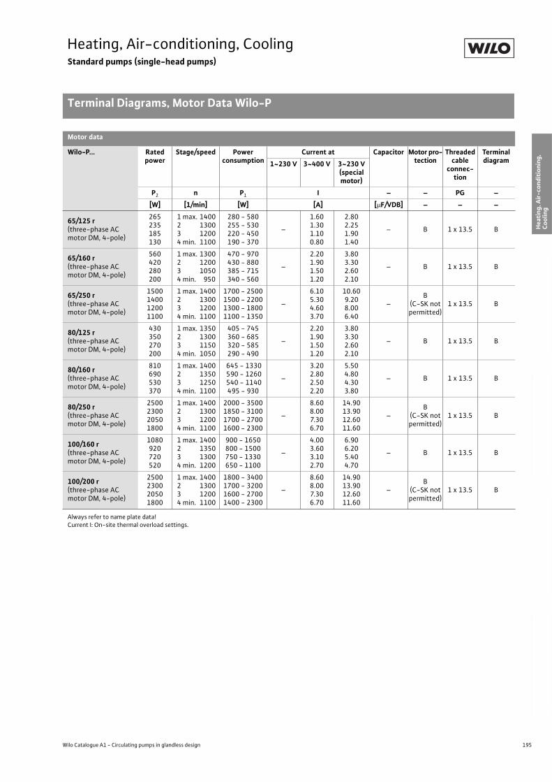
195
Heating, Air-conditioning, CoolingStandard pumps (single-head pumps)
Terminal Diagrams, Motor Data Wilo-P
Wilo Catalogue A1 - Circulating pumps in glandless design
Hea
tin
g, A
ir-c
on
dit
ion
ing
, C
oo
ling
Po
tab
le w
ater
cir
cula
tio
nSo
lar
ther
mal
Serv
ice/
Acc
esso
ries
, Sys
tem
sSw
itch
gea
rs a
nd
Co
ntr
ol
Dev
ices
P
um
p M
anag
emen
t S y
stem
s
65/125 r(three-phase AC motor DM, 4-pole)
265235185130
1 max. 1400 2 13003 12004 min. 1100
280 - 580255 - 530220 - 450190 - 370
–
1.601.301.100.80
2.802.251.901.40
– B 1 x 13.5 B
65/160 r(three-phase AC motor DM, 4-pole)
560420280200
1 max. 1300 2 12003 10504 min. 950
470 - 970430 - 880385 - 715340 - 560
–
2.201.901.501.20
3.803.302.602.10
– B 1 x 13.5 B
65/250 r(three-phase AC motor DM, 4-pole)
1500140012001100
1 max. 1400 2 13003 12004 min. 1100
1700 - 25001500 - 22001300 - 18001100 - 1350
–
6.105.304.603.70
10.609.208.006.40
–B
(C-SK not permitted)
1 x 13.5 B
80/125 r(three-phase AC motor DM, 4-pole)
430350270200
1 max. 1350 2 13003 11504 min. 1050
405 - 745360 - 685320 - 585290 - 490
–
2.201.901.501.20
3.803.302.602.10
– B 1 x 13.5 B
80/160 r(three-phase AC motor DM, 4-pole)
810690530370
1 max. 1400 2 13503 12504 min. 1100
645 - 1330 590 - 1260 540 - 1140495 - 930
–
3.202.802.502.20
5.504.804.303.80
– B 1 x 13.5 B
80/250 r(three-phase AC motor DM, 4-pole)
2500230020501800
1 max. 1400 2 13003 12004 min. 1100
2000 - 35001850 - 31001700 - 27001600 - 2300
–
8.608.007.306.70
14.9013.9012.6011.60
–B
(C-SK not permitted)
1 x 13.5 B
100/160 r(three-phase AC motor DM, 4-pole)
1080920720520
1 max. 1400 2 13503 13004 min. 1200
900 - 1650800 - 1500750 - 1330650 - 1100
–
4.003.603.102.70
6.906.205.404.70
– B 1 x 13.5 B
100/200 r(three-phase AC motor DM, 4-pole)
2500230020501800
1 max. 1400 2 13003 12004 min. 1100
1800 - 34001700 - 32001600 - 27001400 - 2300
–
8.608.007.306.70
14.9013.9012.6011.60
–B
(C-SK not permitted)
1 x 13.5 B
Motor data
Wilo-P... Rated power
Stage/speed Power consumption
Current at Capacitor Motor pro-tection
Threaded cable
connec-tion
Terminal diagram1~230 V 3~400 V 3~230 V
(specialmotor)
P2 n P1 I – – PG –
[W] [1/min] [W] [A] [ F/VDB] – – –
Always refer to name plate data!Current I: On-site thermal overload settings.
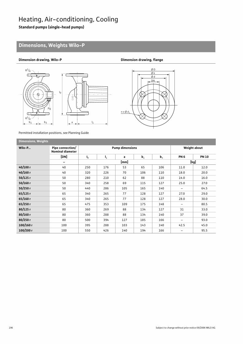
196 Subject to change without prior notice 09/2006 WILO AG
Heating, Air-conditioning, CoolingStandard pumps (single-head pumps)
Dimensions, Weights Wilo-P
Dimension drawing, Wilo-P Dimension drawing, flange
Permitted installation positions, see Planning Guide
Dimensions, Weights
Wilo-P... Pipe connection/Nominal diameter
Pump dimensions Weight about
[DN] I0 l1 a b1 b3 PN 6 PN 10
– [mm] [kg]
40/100 r 40 250 176 53 65 106 11.0 12.0
40/160 r 40 320 226 70 106 110 18.0 20.0
50/125 r 50 280 210 62 88 110 14.0 16.0
50/160 r 50 340 258 69 115 127 25.0 27.0
50/250 r 50 440 286 105 165 140 – 64.5
65/125 r 65 340 265 77 128 127 27.0 29.0
65/160 r 65 340 265 77 128 127 28.0 30.0
65/250 r 65 475 353 109 175 148 – 80.5
80/125 r 80 360 269 88 134 127 31 33.0
80/160 r 80 360 288 88 134 140 37 39.0
80/250 r 80 500 394 127 185 166 – 93.0
100/160 r 100 395 288 103 143 140 42.5 45.0
100/200 r 100 550 426 140 194 166 – 95.5
b1 b3 l1a
l0
Pg
R1/8
R1/8
n x Ø d
Ø D Ø k
DN
Ø d
L
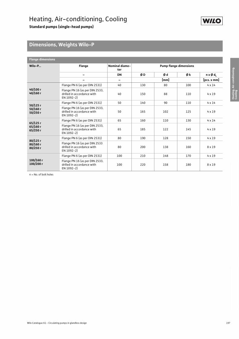
197
Heating, Air-conditioning, CoolingStandard pumps (single-head pumps)
Dimensions, Weights Wilo-P
Wilo Catalogue A1 - Circulating pumps in glandless design
Hea
tin
g, A
ir-c
on
dit
ion
ing
, C
oo
ling
Po
tab
le w
ater
cir
cula
tio
nSo
lar
ther
mal
Serv
ice/
Acc
esso
ries
, Sys
tem
sSw
itch
gea
rs a
nd
Co
ntr
ol
Dev
ices
P
um
p M
anag
emen
t S y
stem
s
Flange dimensions
Wilo-P... Flange Nominal diame-ter
Pump flange dimensions
– DN Ø D Ø d Ø k n x Ø dL
– – [mm] [pcs. x mm]
40/100 r40/160 r
Flange PN 6 (as per DIN 2531) 40 130 80 100 4 x 14
Flange PN 16 (as per DIN 2533,drilled in accordance with EN 1092-2)
40 150 88 110 4 x 19
50/125 r50/160 r50/250 r
Flange PN 6 (as per DIN 2531) 50 140 90 110 4 x 14
Flange PN 16 (as per DIN 2533,drilled in accordance with EN 1092-2)
50 165 102 125 4 x 19
65/125 r65/160 r65/250 r
Flange PN 6 (as per DIN 2531) 65 160 110 130 4 x 14
Flange PN 16 (as per DIN 2533,drilled in accordance with EN 1092-2)
65 185 122 145 4 x 19
80/125 r80/160 r80/250 r
Flange PN 6 (as per DIN 2531) 80 190 128 150 4 x 19
Flange PN 16 (as per DIN 2533drilled in accordance with EN 1092-2)
80 200 138 160 8 x 19
100/160 r100/200 r
Flange PN 6 (as per DIN 2531) 100 210 148 170 4 x 19
Flange PN 16 (as per DIN 2533,drilled in accordance with EN 1092-2)
100 220 158 180 8 x 19
n = No. of bolt holes
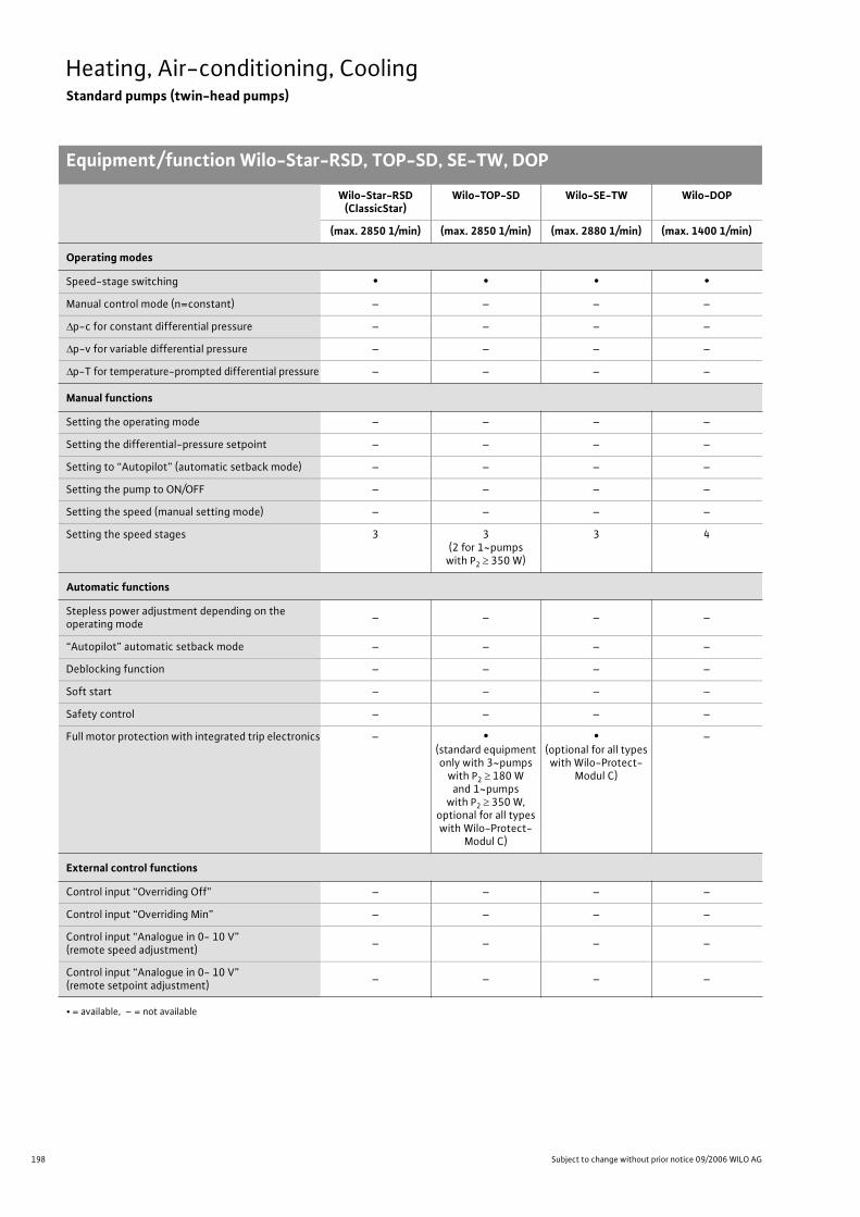
198 Subject to change without prior notice 09/2006 WILO AG
Heating, Air-conditioning, CoolingStandard pumps (twin-head pumps)
Equipment/function Wilo-Star-RSD, TOP-SD, SE-TW, DOP
Wilo-Star-RSD (ClassicStar)
Wilo-TOP-SD Wilo-SE-TW Wilo-DOP
(max. 2850 1/min) (max. 2850 1/min) (max. 2880 1/min) (max. 1400 1/min)
Operating modes
Speed-stage switching • • • •
Manual control mode (n=constant) – – – –
p-c for constant differential pressure – – – –
p-v for variable differential pressure – – – –
p-T for temperature-prompted differential pressure – – – –
Manual functions
Setting the operating mode – – – –
Setting the differential-pressure setpoint – – – –
Setting to “Autopilot” (automatic setback mode) – – – –
Setting the pump to ON/OFF – – – –
Setting the speed (manual setting mode) – – – –
Setting the speed stages 3 3(2 for 1~pumps
with P2 350 W)
3 4
Automatic functions
Stepless power adjustment depending on the operating mode
– – – –
“Autopilot” automatic setback mode – – – –
Deblocking function – – – –
Soft start – – – –
Safety control – – – –
Full motor protection with integrated trip electronics – •(standard equipmentonly with 3~pumps
with P2 180 W and 1~pumps
with P2 350 W,optional for all types with Wilo-Protect-
Modul C)
•(optional for all types with Wilo-Protect-
Modul C)
–
External control functions
Control input “Overriding Off” – – – –
Control input “Overriding Min” – – – –
Control input “Analogue in 0- 10 V” (remote speed adjustment)
– – – –
Control input “Analogue in 0- 10 V” (remote setpoint adjustment)
– – – –
• = available, – = not available
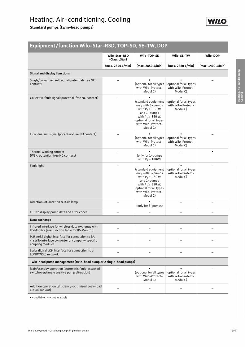
199
Heating, Air-conditioning, CoolingStandard pumps (twin-head pumps)
Equipment/function Wilo-Star-RSD, TOP-SD, SE-TW, DOP
Wilo Catalogue A1 - Circulating pumps in glandless design
Hea
tin
g, A
ir-c
on
dit
ion
ing
, C
oo
ling
Po
tab
le w
ater
cir
cula
tio
nSo
lar
ther
mal
Serv
ice/
Acc
esso
ries
, Sys
tem
sSw
itch
gea
rs a
nd
Co
ntr
ol
Dev
ices
P
um
p M
anag
emen
t S y
stem
s
Signal and display functions
Single/collective fault signal (potential-free NC contact)
– •(optional for all types with Wilo-Protect-
Modul C)
•(optional for all types with Wilo-Protect-
Modul C)
–
Collective fault signal (potential-free NC contact) – •(standard equipmentonly with 3~pumps
with P2 180 W and 1~pumps
with P2 350 W, optional for all types with Wilo-Protect-
Modul C)
•(optional for all types with Wilo-Protect-
Modul C)
–
Individual run signal (potential-free NO contact) – •(optional for all types with Wilo-Protect-
Modul C)
•(optional for all types with Wilo-Protect-
Modul C)
–
Thermal winding contact (WSK, potential-free NC contact)
– •(only for 1~pumps
with P2 = 180W)
– •
Fault light – •(standard equipmentonly with 3~pumps
with P2 180 W and 1~pumps
with P2 350 W, optional for all types with Wilo-Protect-
Modul C)
•(optional for all types with Wilo-Protect-
Modul C)
–
Direction-of-rotation telltale lamp – •(only for 3~pumps)
– –
LCD to display pump data and error codes – – – –
Data exchange
Infrared interface for wireless data exchange with IR-Monitor (see function table for IR-Monitor)
– – – –
PLR serial digital interface for connection to BA via Wilo interface converter or company-specific coupling modules
– – – –
Serial digital LON interface for connection to a LONWORKS network
– – – –
Twin-head pump management (twin-head pump or 2 single-head pumps)
Main/standby operation (automatic fault-actuated switchover/time-sensitive pump alteration)
– •(optional for all types with Wilo-Protect-
Modul C)
•(optional for all types with Wilo-Protect-
Modul C)
–
Addition operation (efficiency-optimised peak-load cut-in and out)
– – – –
Wilo-Star-RSD (ClassicStar)
Wilo-TOP-SD Wilo-SE-TW Wilo-DOP
(max. 2850 1/min) (max. 2850 1/min) (max. 2880 1/min) (max. 1400 1/min)
• = available, – = not available
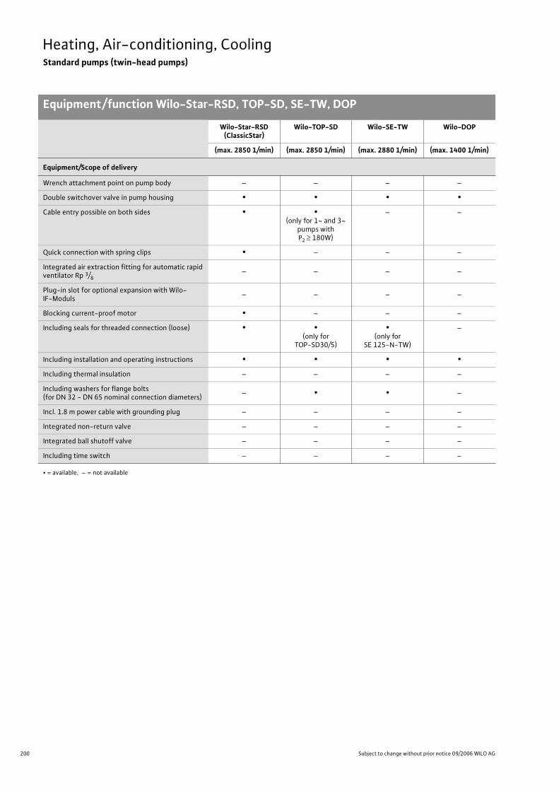
200 Subject to change without prior notice 09/2006 WILO AG
Heating, Air-conditioning, CoolingStandard pumps (twin-head pumps)
Equipment/function Wilo-Star-RSD, TOP-SD, SE-TW, DOP
Equipment/Scope of delivery
Wrench attachment point on pump body – – – –
Double switchover valve in pump housing • • • •
Cable entry possible on both sides • •(only for 1~ and 3~
pumps with P2 180W)
– –
Quick connection with spring clips • – – –
Integrated air extraction fitting for automatic rapid ventilator Rp 3/8
– – – –
Plug-in slot for optional expansion with Wilo-IF-Moduls
– – – –
Blocking current-proof motor • – – –
Including seals for threaded connection (loose) • •(only for
TOP-SD30/5)
•(only for
SE 125-N-TW)
–
Including installation and operating instructions • • • •
Including thermal insulation – – – –
Including washers for flange bolts(for DN 32 - DN 65 nominal connection diameters)
– • • –
Incl. 1.8 m power cable with grounding plug – – – –
Integrated non-return valve – – – –
Integrated ball shutoff valve – – – –
Including time switch – – – –
Wilo-Star-RSD (ClassicStar)
Wilo-TOP-SD Wilo-SE-TW Wilo-DOP
(max. 2850 1/min) (max. 2850 1/min) (max. 2880 1/min) (max. 1400 1/min)
• = available, – = not available

201
Heating, Air-conditioning, CoolingStandard pumps (twin-head pumps)
Wilo Catalogue A1 - Circulating pumps in glandless design
Hea
tin
g, A
ir-c
on
dit
ion
ing
, C
oo
ling
Po
tab
le w
ater
cir
cula
tio
nSo
lar
ther
mal
Serv
ice/
Acc
esso
ries
, Sys
tem
sSw
itch
gea
rs a
nd
Co
ntr
ol
Dev
ices
P
um
p M
anag
emen
t S y
stem
s
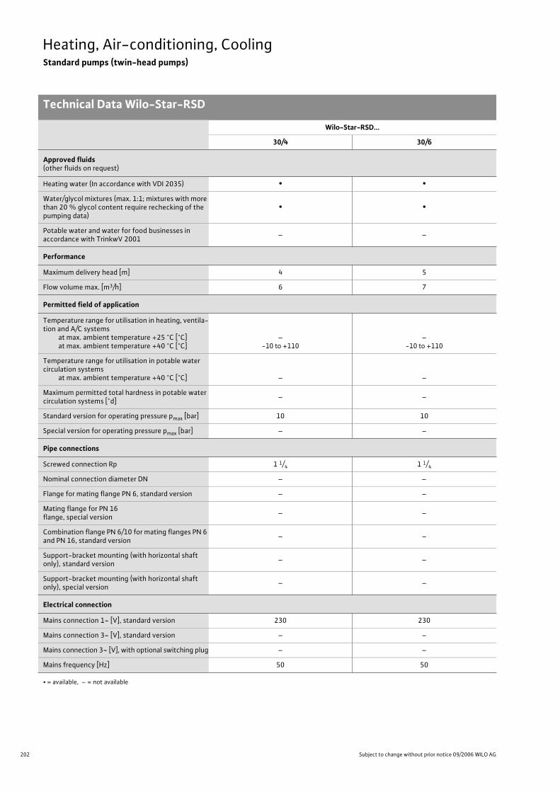
202 Subject to change without prior notice 09/2006 WILO AG
Heating, Air-conditioning, CoolingStandard pumps (twin-head pumps)
Technical Data Wilo-Star-RSD
Wilo-Star-RSD...
30/4 30/6
Approved fluids(other fluids on request)
Heating water (In accordance with VDI 2035) • •
Water/glycol mixtures (max. 1:1; mixtures with more than 20 % glycol content require rechecking of the pumping data)
• •
Potable water and water for food businesses in accordance with TrinkwV 2001
– –
Performance
Maximum delivery head [m] 4 5
Flow volume max. [m3/h] 6 7
Permitted field of application
Temperature range for utilisation in heating, ventila-tion and A/C systems
at max. ambient temperature +25 °C [°C]at max. ambient temperature +40 °C [°C]
–-10 to +110
–-10 to +110
Temperature range for utilisation in potable water circulation systems
at max. ambient temperature +40 °C [°C] – –
Maximum permitted total hardness in potable water circulation systems [°d]
– –
Standard version for operating pressure pmax [bar] 10 10
Special version for operating pressure pmax [bar] – –
Pipe connections
Screwed connection Rp 1 1/4 1 1/4
Nominal connection diameter DN – –
Flange for mating flange PN 6, standard version – –
Mating flange for PN 16 flange, special version
– –
Combination flange PN 6/10 for mating flanges PN 6 and PN 16, standard version
– –
Support-bracket mounting (with horizontal shaft only), standard version
– –
Support-bracket mounting (with horizontal shaft only), special version
– –
Electrical connection
Mains connection 1~ [V], standard version 230 230
Mains connection 3~ [V], standard version – –
Mains connection 3~ [V], with optional switching plug – –
Mains frequency [Hz] 50 50
• = available, – = not available
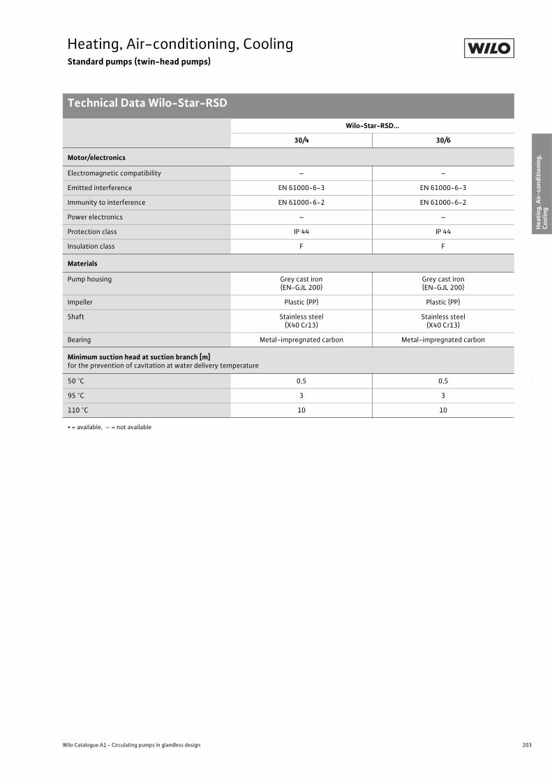
203
Heating, Air-conditioning, CoolingStandard pumps (twin-head pumps)
Technical Data Wilo-Star-RSD
Wilo Catalogue A1 - Circulating pumps in glandless design
Hea
tin
g, A
ir-c
on
dit
ion
ing
, C
oo
ling
Po
tab
le w
ater
cir
cula
tio
nSo
lar
ther
mal
Serv
ice/
Acc
esso
ries
, Sys
tem
sSw
itch
gea
rs a
nd
Co
ntr
ol
Dev
ices
P
um
p M
anag
emen
t S y
stem
s
Motor/electronics
Electromagnetic compatibility – –
Emitted interference EN 61000-6-3 EN 61000-6-3
Immunity to interference EN 61000-6-2 EN 61000-6-2
Power electronics – –
Protection class IP 44 IP 44
Insulation class F F
Materials
Pump housing Grey cast iron (EN-GJL 200)
Grey cast iron (EN-GJL 200)
Impeller Plastic (PP) Plastic (PP)
Shaft Stainless steel (X40 Cr13)
Stainless steel (X40 Cr13)
Bearing Metal-impregnated carbon Metal-impregnated carbon
Minimum suction head at suction branch [m]for the prevention of cavitation at water delivery temperature
50 °C 0,5 0,5
95 °C 3 3
110 °C 10 10
Wilo-Star-RSD...
30/4 30/6
• = available, – = not available
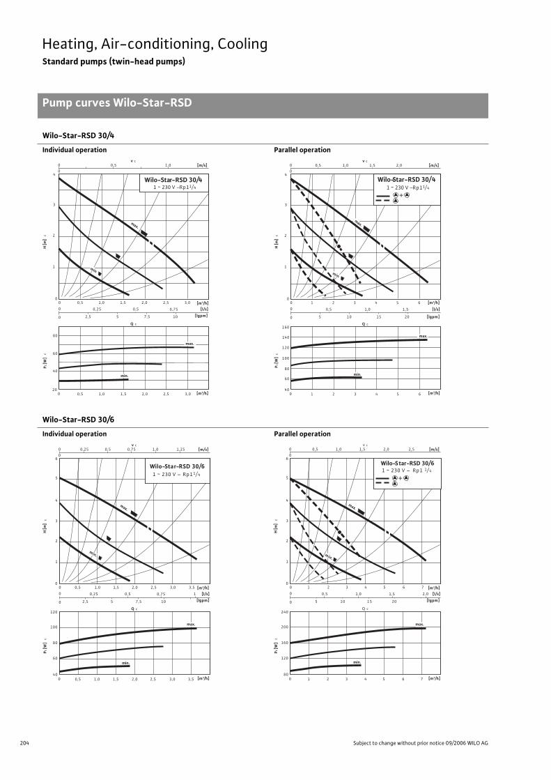
204 Subject to change without prior notice 09/2006 WILO AG
Heating, Air-conditioning, CoolingStandard pumps (twin-head pumps)
Pump curves Wilo-Star-RSD
Wilo-Star-RSD 30/4
Individual operation Parallel operation
Wilo-Star-RSD 30/6
Individual operation Parallel operation
c
Q c
c
0
00
0
0
0,5
[l/s]
020
Wilo-Star-RSD 30/41 ~ 230 V – Rp11/4
0,5
1,0
[m/s]
1
2
3
4
v c
0
0,5
0,75
80
60
40
1,0
1,0 1,5 2,0 2,5
max.
0,25
0,5 1,5 2,0 2,5
2,5 5 7,5 10
3,0
min
3,0
max.
min.
P1 [W
] H
[m]
[m3/h]
[lgpm]
[m3/h]
P1 [W
] c
Q c
H [m
] c
0
00
0
0
1 [m3/h]
[l/s]
[lgpm]
040
1,0
2
[m/s]
1
2
3
4
v c
0
0,5
1,5
140
100
80
1,0
2 3 4 5
0,5
1 3 4 5
5 10 15 20
6
min
6
1,5 2,0
max.
160
120
60
Wilo-Star-RSD 30/41 ~ 230 V – Rp11/4
max.
min.
[m3/h]
+
c
Q c
c
0
00
0
0
0,5
[l/s]
040
Wilo-Star-RSD 30/61 ~ 230 V – Rp11/ 4
0,5
1,0
[m/s]
1
v c
0
0,5
0,75
100
80
60
1,0
1,0 1,5 2,0 2,5
0,25
0,5 1,5 2,0 2,5
min.
2,5 5 7,5 10
3,0
3,0
0,25 0,75 1,25
2
3
4
5
6
3,5
max.
min.
1
120
3,5
max.
P1 [W
] H
[m]
[m3/h]
[lgpm]
[m3/h]
c
Q c
c
0
00
0
0
1
[l/s]
080
1,0
2
[m/s]
1
v c
0
1,0
1,5
200
160
120
2,0
2 3 4 5
0,5
1 3 4 5
5 10 15 20
6
6
0,5 1,5 2,5
2
3
4
5
6
7
max.
2,0
240
7
min.
min.
max.
Wilo-Star-RSD 30/61 ~ 230 V – Rp1 1/ 4
P1 [W
] H
[m]
[m3/h]
[lgpm]
[m3/h]
+
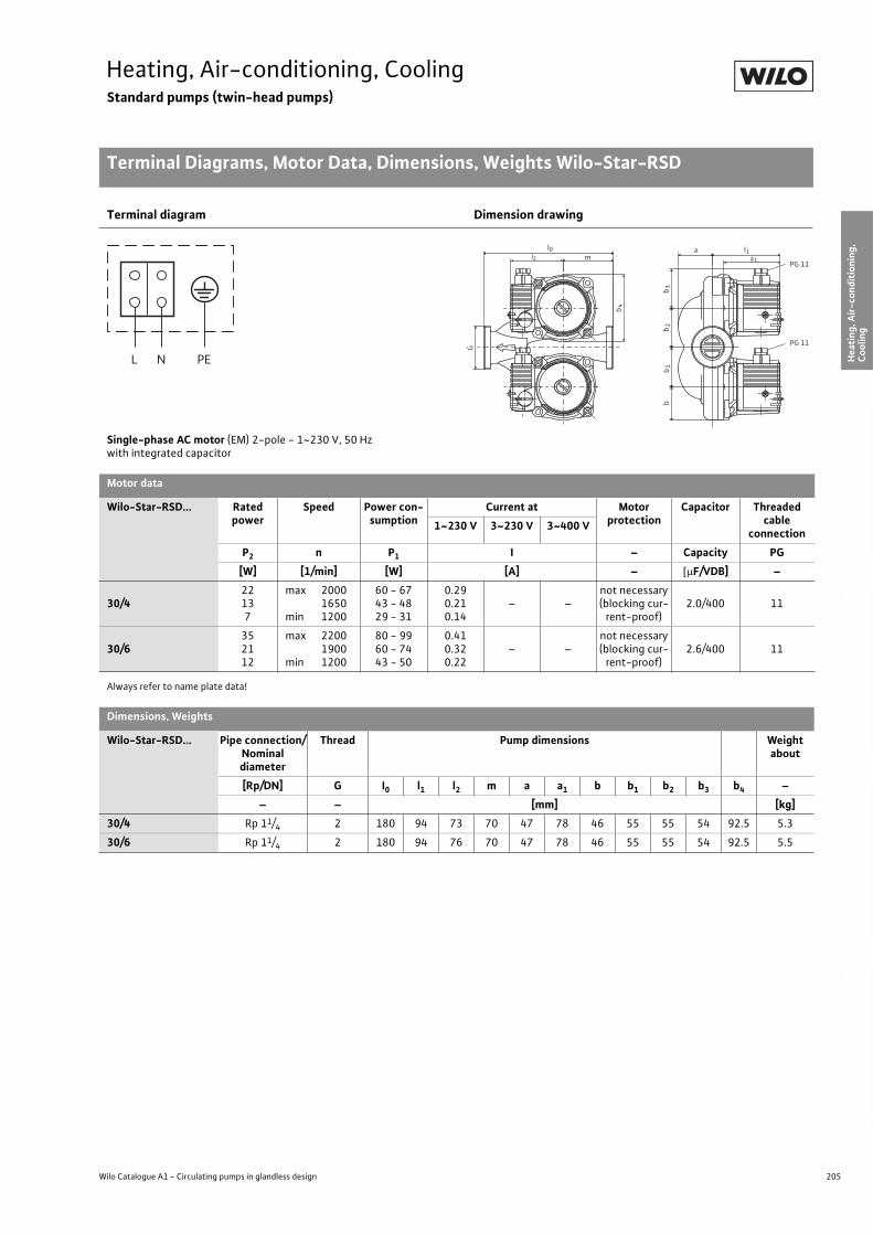
205
Heating, Air-conditioning, CoolingStandard pumps (twin-head pumps)
Terminal Diagrams, Motor Data, Dimensions, Weights Wilo-Star-RSD
Wilo Catalogue A1 - Circulating pumps in glandless design
Hea
tin
g, A
ir-c
on
dit
ion
ing
, C
oo
ling
Po
tab
le w
ater
cir
cula
tio
nSo
lar
ther
mal
Serv
ice/
Acc
esso
ries
, Sys
tem
sSw
itch
gea
rs a
nd
Co
ntr
ol
Dev
ices
P
um
p M
anag
emen
t S y
stem
s
Always refer to name plate data!
Terminal diagram Dimension drawing
Single-phase AC motor (EM) 2-pole - 1~230 V, 50 Hzwith integrated capacitor
Motor data
Wilo-Star-RSD... Rated power
Speed Power con-sumption
Current at Motor protection
Capacitor Threaded cable
connection1~230 V 3~230 V 3~400 V
P2 n P1 I – Capacity PG
[W] [1/min] [W] [A] – F/VDB] –
30/422137
max 2000 1650
min 1200
60 - 6743 - 4829 - 31
0.290.210.14
– –not necessary (blocking cur-
rent-proof)2.0/400 11
30/6352112
max 2200 1900
min 1200
80 - 9960 - 7443 - 50
0.410.320.22
– –not necessary (blocking cur-
rent-proof)2.6/400 11
Dimensions, Weights
Wilo-Star-RSD... Pipe connection/Nominal diameter
Thread Pump dimensions Weight about
[Rp/DN] G I0 l1 l2 m a a1 b b1 b2 b3 b4 –
– – [mm] [kg]
30/4 Rp 11/4 2 180 94 73 70 47 78 46 55 55 54 92.5 5.3
30/6 Rp 11/4 2 180 94 76 70 47 78 46 55 55 54 92.5 5.5
L N PE
a
PG 11
l0 l1
b3
b2
b1
b4
G
b
l2 a1mPG 11
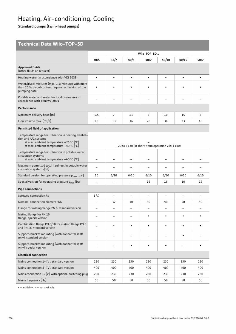
206 Subject to change without prior notice 09/2006 WILO AG
Heating, Air-conditioning, CoolingStandard pumps (twin-head pumps)
Technical Data Wilo-TOP-SD
Wilo-TOP-SD...
30/5 32/7 40/3 40/7 40/10 40/15 50/7
Approved fluids(other fluids on request)
Heating water (In accordance with VDI 2035) • • • • • • •
Water/glycol mixtures (max. 1:1; mixtures with more than 20 % glycol content require rechecking of the pumping data)
• • • • • • •
Potable water and water for food businesses in accordance with TrinkwV 2001
– – – – – – –
Performance
Maximum delivery head [m] 5,5 7 3,5 7 10 15 7
Flow volume max. [m3/h] 10 13 16 28 34 33 45
Permitted field of application
Temperature range for utilisation in heating, ventila-tion and A/C systems
at max. ambient temperature +25 °C [°C]at max. ambient temperature +40 °C [°C]
–-20 to +130 (in short-term operation 2 h: +140)
Temperature range for utilisation in potable water circulation systems
at max. ambient temperature +40 °C [°C] – – – – – – –
Maximum permitted total hardness in potable water circulation systems [°d]
– – – – – – –
Standard version for operating pressure pmax [bar] 10 6/10 6/10 6/10 6/10 6/10 6/10
Special version for operating pressure pmax [bar] – – – 16 16 16 16
Pipe connections
Screwed connection Rp 1 1/4 – – – – – –
Nominal connection diameter DN – 32 40 40 40 50 50
Flange for mating flange PN 6, standard version – – – – – – –
Mating flange for PN 16 flange, special version
– – – • • • •
Combination flange PN 6/10 for mating flange PN 6 and PN 16, standard version
– • • • • • •
Support-bracket mounting (with horizontal shaft only), standard version
– – – – – • –
Support-bracket mounting (with horizontal shaft only), special version
– – • • • – •
Electrical connection
Mains connection 1~ [V], standard version 230 230 230 230 230 230 230
Mains connection 3~ [V], standard version 400 400 400 400 400 400 400
Mains connection 3~ [V], with optional switching plug 230 230 230 230 230 230 230
Mains frequency [Hz] 50 50 50 50 50 50 50
• = available, – = not available

207
Heating, Air-conditioning, CoolingStandard pumps (twin-head pumps)
Technical Data Wilo-TOP-SD
Wilo Catalogue A1 - Circulating pumps in glandless design
Hea
tin
g, A
ir-c
on
dit
ion
ing
, C
oo
ling
Po
tab
le w
ater
cir
cula
tio
nSo
lar
ther
mal
Serv
ice/
Acc
esso
ries
, Sys
tem
sSw
itch
gea
rs a
nd
Co
ntr
ol
Dev
ices
P
um
p M
anag
emen
t S y
stem
s
Motor/electronics
Electromagnetic compatibility – – – – – – –
Emitted interference EN 61000-6-3
Immunity to interference EN 61000-6-2
Power electronics – – – – – – –
Protection class IP 44 IP 44 IP 44 IP 44 IP 44 IP 44 IP 44
Insulation class F F F F F F F
Materials
Pump housing
Gre
y ca
st ir
on
(EN
-GJL
20
0)
Grey cast iron (EN-GJL 250)
Impeller
Plas
tic
(PPE
) T
rad
e n
ame:
No
ryl
Plas
tic
50
(PPS
-%
GF)
Plas
tic
(PPE
) T
rad
e n
ame:
No
ryl
Plastic (PPS - % GF)50
Shaft Stainless steel (X46 Cr13)
Bearing Metal-impregnated carbon
Minimum suction head at suction branch [m]for the prevention of cavitation at water delivery temperature
50 °C 0,5 0,5 0,5 0,5 0,5 3 3
95 °C 5 5 5 5 5 10 10
110 °C 11 11 11 11 11 16 16
130 °C 24 24 24 24 24 29 29
Wilo-TOP-SD...
30/5 32/7 40/3 40/7 40/10 40/15 50/7
• = available, – = not available
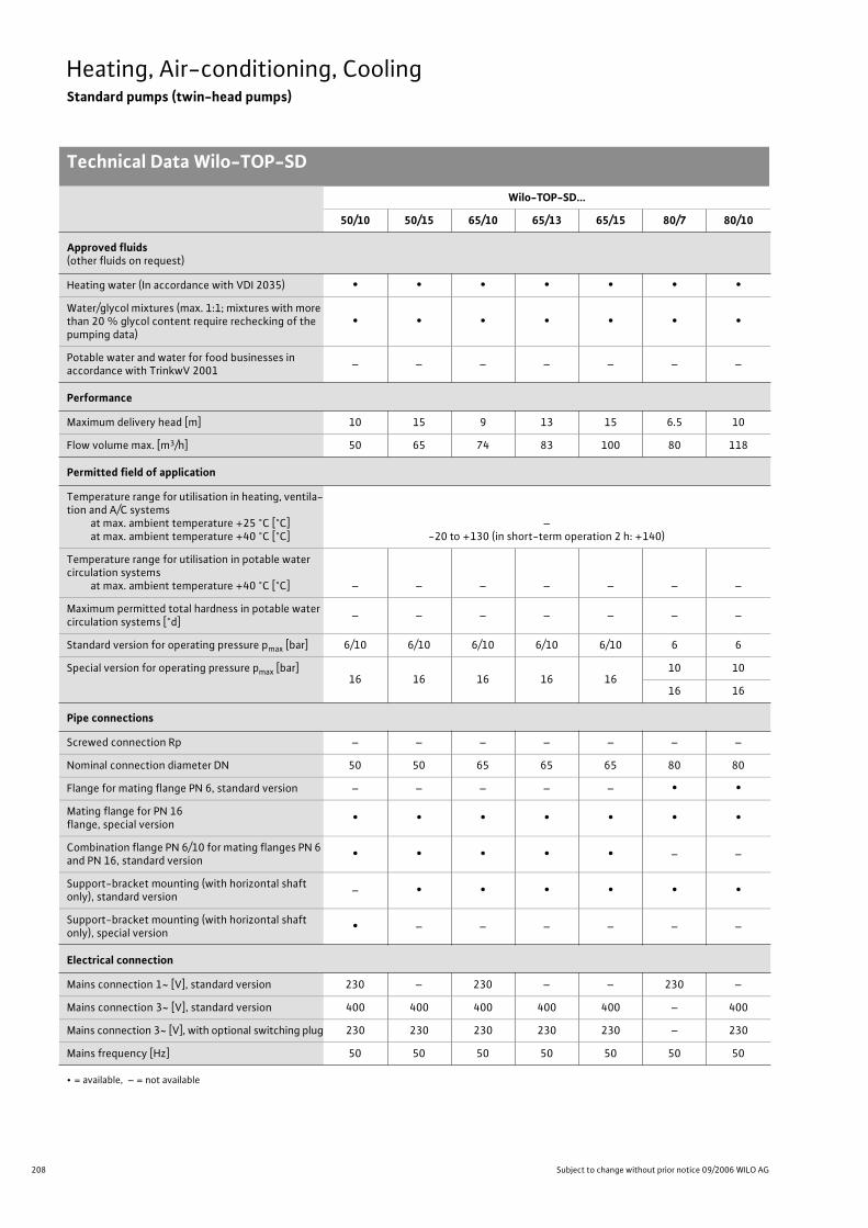
208 Subject to change without prior notice 09/2006 WILO AG
Heating, Air-conditioning, CoolingStandard pumps (twin-head pumps)
Technical Data Wilo-TOP-SD
Wilo-TOP-SD...
50/10 50/15 65/10 65/13 65/15 80/7 80/10
Approved fluids(other fluids on request)
Heating water (In accordance with VDI 2035) • • • • • • •
Water/glycol mixtures (max. 1:1; mixtures with more than 20 % glycol content require rechecking of the pumping data)
• • • • • • •
Potable water and water for food businesses in accordance with TrinkwV 2001
– – – – – – –
Performance
Maximum delivery head [m] 10 15 9 13 15 6.5 10
Flow volume max. [m3/h] 50 65 74 83 100 80 118
Permitted field of application
Temperature range for utilisation in heating, ventila-tion and A/C systems
at max. ambient temperature +25 °C [°C]at max. ambient temperature +40 °C [°C]
–-20 to +130 (in short-term operation 2 h: +140)
Temperature range for utilisation in potable water circulation systems
at max. ambient temperature +40 °C [°C] – – – – – – –
Maximum permitted total hardness in potable water circulation systems [°d]
– – – – – – –
Standard version for operating pressure pmax [bar] 6/10 6/10 6/10 6/10 6/10 6 6
Special version for operating pressure pmax [bar]16 16 16 16 16
10 10
16 16
Pipe connections
Screwed connection Rp – – – – – – –
Nominal connection diameter DN 50 50 65 65 65 80 80
Flange for mating flange PN 6, standard version – – – – – • •
Mating flange for PN 16 flange, special version
• • • • • • •
Combination flange PN 6/10 for mating flanges PN 6 and PN 16, standard version
• • • • • – –
Support-bracket mounting (with horizontal shaft only), standard version
– • • • • • •
Support-bracket mounting (with horizontal shaft only), special version
• – – – – – –
Electrical connection
Mains connection 1~ [V], standard version 230 – 230 – – 230 –
Mains connection 3~ [V], standard version 400 400 400 400 400 – 400
Mains connection 3~ [V], with optional switching plug 230 230 230 230 230 – 230
Mains frequency [Hz] 50 50 50 50 50 50 50
• = available, – = not available

209
Heating, Air-conditioning, CoolingStandard pumps (twin-head pumps)
Technical Data Wilo-TOP-SD
Wilo Catalogue A1 - Circulating pumps in glandless design
Hea
tin
g, A
ir-c
on
dit
ion
ing
, C
oo
ling
Po
tab
le w
ater
cir
cula
tio
nSo
lar
ther
mal
Serv
ice/
Acc
esso
ries
, Sys
tem
sSw
itch
gea
rs a
nd
Co
ntr
ol
Dev
ices
P
um
p M
anag
emen
t S y
stem
s
Motor/electronics
Electromagnetic compatibility – – – – – – –
Emitted interference EN 61000-6-3
Immunity to interference EN 61000-6-2
Power electronics – – – – – – –
Protection class IP 44 IP 44 IP 44 IP 44 IP 44 IP 44 IP 44
Insulation class F F F F F F F
Materials
Pump housing Grey cast iron (EN-GJL 250)
Impeller Plastic (PPS - 50% GF)
Shaft Stainless steel (X46 Cr13)
Bearing Metal-impregnated carbon
Minimum suction head at suction branch [m]for the prevention of cavitation at water delivery temperature
50 °C 3 3 3 3 3 3 3
95 °C 10 10 10 10 10 10 10
110 °C 16 16 16 16 16 16 16
130 °C 29 29 29 29 29 29 29
Wilo-TOP-SD...
50/10 50/15 65/10 65/13 65/15 80/7 80/10
• = available, – = not available
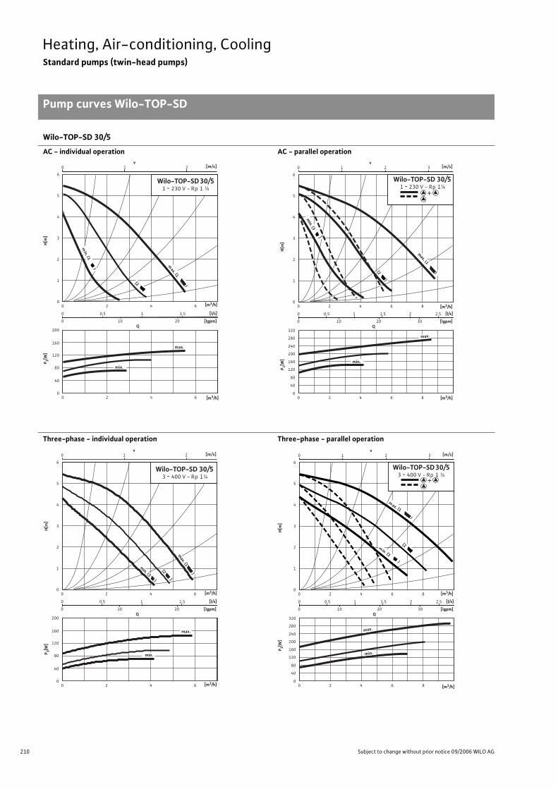
210 Subject to change without prior notice 09/2006 WILO AG
Heating, Air-conditioning, CoolingStandard pumps (twin-head pumps)
Pump curves Wilo-TOP-SD
Wilo-TOP-SD 30/5
AC - individual operation AC - parallel operation
Three-phase - individual operation Three-phase - parallel operation
Q [lgpm]
0
320
240
280
160
200
80
120
40
0 2 0
0
0
0
[l/s]
1
4
5
6
3
2
2
0,5
10 20 30
1,5 2,5 2
4 6 8
3 2 1 0 [m/s] v
1
4 6 8
max.
min.
min. (3 )
max. (1 )
P 1[W]
H[m
]
+
[m3/h]
[m3/h]
(2 )
Wilo-TOP-SD 30/5 1 ~ 230 V - Rp 1¼
Q [lgpm]
0
160
200
80
120
40
0 2 0
0
0
0
[l/s]
1
4
5
6
3
2
2
0,5
10 20
1,5
4 6
2 1 0 [m/s] v
1
4 6
m
)
in. (3
(2 )
m ax.
m in.
m ax. (1 )
[m3/h]
[m3/h]
P 1[W]
H[m
]
Wilo-TOP-SD 30/5 1 ~ 230 V - Rp 1 ¼
Q [lgpm]
0
160
200
80
120
40
0 2 0
0
0
0
[l/s]
1
4
5
6
3
2
2
0,5
10 20
1,5
4 6
2 1 0 [m/s] v
1
4 6
max.
min.
[m3/h]
[m3/h]
P 1[W]
H[m
]
Wilo-TOP-SD 30/5 3 ~ 400 V - Rp 1¼
max. (1 )
(2 )
min. (3 )
Q [lgpm]
0
320
240
280
160
200
80
120
40
0 2 0
0
0
0
[l/s]
1
4
5
6
3
2
2
0,5
10 20 30
1,5 2,5 2
4 6 8
3 2 1 0 [m/s] v
1
4 6 8
m ax.
m in.
m in. (3 )
m ax. (1 )
(2 )
Wilo-TOP-SD 30/5 3 ~ 400 V - Rp 1 ¼
P 1[W]
H[m
]
+
[m3/h]
[m3/h]
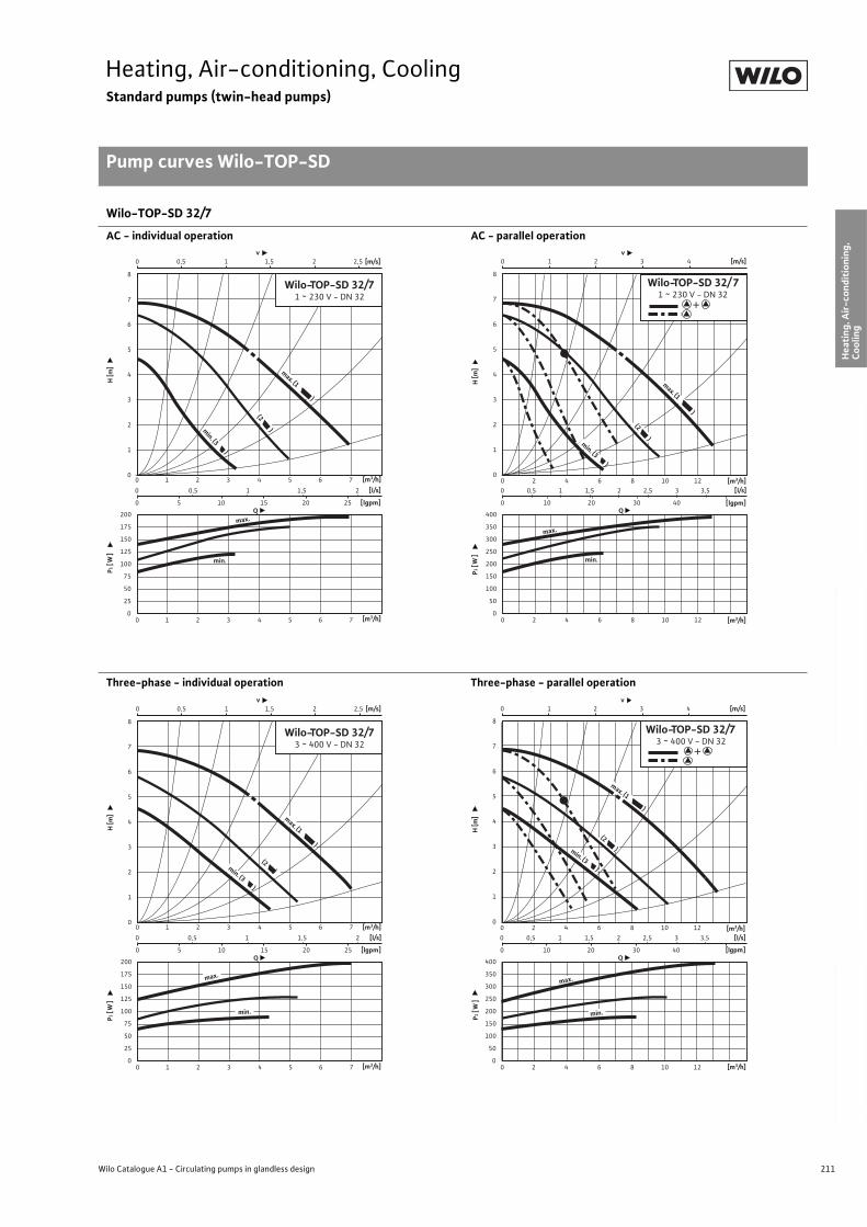
211
Heating, Air-conditioning, CoolingStandard pumps (twin-head pumps)
Pump curves Wilo-TOP-SD
Wilo Catalogue A1 - Circulating pumps in glandless design
Hea
tin
g, A
ir-c
on
dit
ion
ing
, C
oo
ling
Po
tab
le w
ater
cir
cula
tio
nSo
lar
ther
mal
Serv
ice/
Acc
esso
ries
, Sys
tem
sSw
itch
gea
rs a
nd
Co
ntr
ol
Dev
ices
P
um
p M
anag
emen
t S y
stem
s
Wilo-TOP-SD 32/7
AC - individual operation AC - parallel operation
Three-phase - individual operation Three-phase - parallel operation
0 0,5 1 1,5 2
0 5 10 15 20 25
0 0,5 1 1,5 2 2,5
0 1 2 3 4 5 6 7
0 1 2 3 4 5 6 7
v [m/s]
Q[lgpm]
200
175
150
125
100
75
50
25
0
8
7
6
5
4
3
2
1
0
[l/s]
min.
max.
Wilo-TOP-SD 32/71 ~ 230 V - DN 32
(2 )
max. (1 )
min. (3 )
P1 [
W]
H [m
]
[m3/h]
[m3/h]
400
350
300
250
200
150
100
50
0
0 0,5 1 1,5 2 2,5 3 3,5
0 10 20 30 40
0 1 2 3 4
0 2 4 6 8 10 12
0 2 4 6 8 10 12
v [m/s]
Q[lgpm]
8
7
6
5
4
3
2
1
0
[l/s]
min.
Wilo-TOP-SD 32/ 7 1 ~ 230 V - DN 32
(2 )
max.
max. (1 )
min. (3 )P1
[W
]H
[m]
[m3/h]
[m3/h]
+
0 0,5 1 1,5 2
0 5 10 15 20 25
0 0,5 1 1,5 2 2,5
0 1 2 3 4 5 6 7
0 1 2 3 4 5 6 7
v [m/s]
P1 [
W]
H [m
]
Q
[m3/h]
[lgpm]
200
175
150
125
100
75
50
25
0
8
7
6
5
4
3
2
1
0
[l/s]
(2 )
Wilo-TOP-SD 32/73 ~ 400 V - DN 32
max. (1 )
min. (3 )
max.
min.
[m3/h]
400
350
300
250
200
150
100
50
0
0 0,5 1 1,5 2 2,5 3 3,5
0 10 20 30 40
0 1 2 3 4
0 2 4 6 8 10 12
0 2 4 6 8 10 12
v [m/s]
Q[lgpm]
8
7
6
5
4
3
2
1
0
[l/s]
(2 )
Wilo-TOP-SD 32/7 3 ~ 400 V - DN 32
min.
max.
max. (1 )
min. (3 )
H [m
]
P1 [
W]
[m3/h]
[m3/h]
+
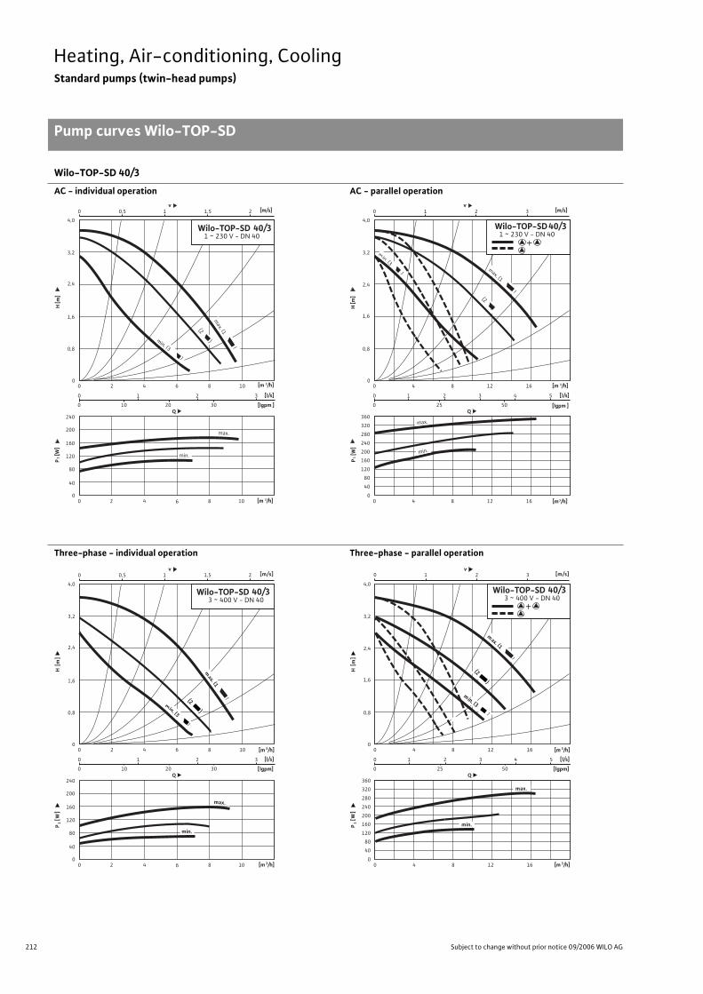
212 Subject to change without prior notice 09/2006 WILO AG
Heating, Air-conditioning, CoolingStandard pumps (twin-head pumps)
Pump curves Wilo-TOP-SD
Wilo-TOP-SD 40/3
AC - individual operation AC - parallel operation
Three-phase - individual operation Three-phase - parallel operation
Q
0
240
160
200
80
120
40
0
0
0
0
[ l/s]
0,8
3,2
4,0
2,4
1,6
2
1
10 20 30
3
4 6 8 10
2 0,5 0 [m/s] v
1 1,5
2
2 0 4 6 8 10
max.
min.
Wilo-TOP-SD 40/3 1 ~ 230 V - DN 40
min. (3 )
(2 ) m
ax. (1
)
P 1 [
W]
H [m
]
[m 3 /h]
[lgpm ]
[m 3 /h]
Q
0
320
360
240
280
160
200
80
120
40
0
0
0
0
[ l/s]
0,8
3,2
4,0
2,4
1,6
4
1
25
3 5 4
8 12 16
50
Wilo-TOP-SD 40/3 1 ~ 230 V - DN 40
3 2 1 0 [m/s] v
2
m in. (3 )
max. (1
) (2 )
4 0 8 12 16
max.
min.
P 1 [
W]
H [m
]
[m 3 /h]
[lgpm ]
[m 3 /h]
+
0,5 0 1 1,5 2
Q [lgpm]
0
240
160
200
80
120
40
0
0
0
0
[l/s]
0,8
3,2
4,0
2,4
1,6
[m 3 /h] 2
1
10 20 30
3
4 6 8 10
[m/s] v
H
[ m
]
2
[m 3 /h]
P 1 [
W]
2 0 4 6 8 10
m ax.
m in.
Wilo-TOP-SD 3 ~ 400 V - DN 40
40/3
m in. (3 )
(2 )
m ax. (1
)
Q [lgpm]
0
320
360
1 0 2 3
240
280
160
200
80
120
40
0
0
0
0
[l/s]
0,8
3,2
4,0
2,4
1,6
[m 3 /h] 4
1
25
3 5 4
8 12 16
50
Wilo-TOP-SD 3 ~ 400 V - DN 40
[m/s] v
H
[ m
]
2
[m 3 /h]
P 1 [
W]
40/3
min. (3 )
m ax. (1 )
(2 )
4 0 8 12 16
m ax.
m in.
+
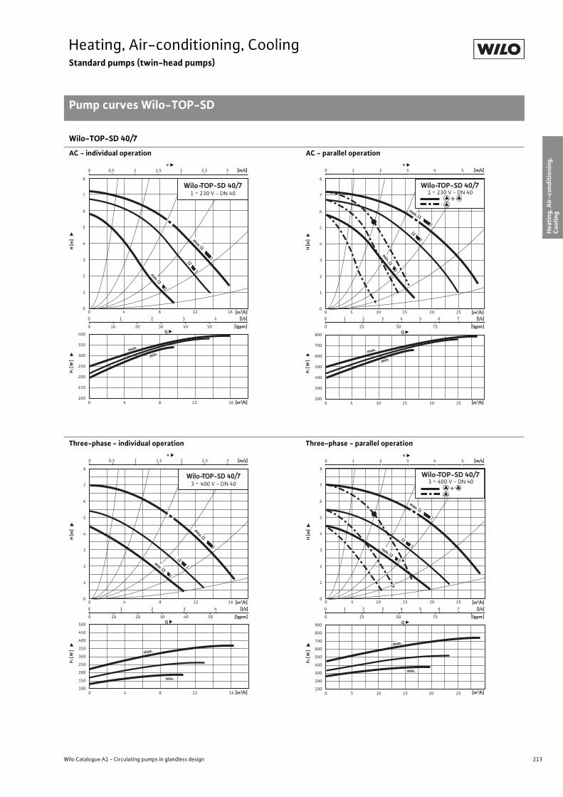
213
Heating, Air-conditioning, CoolingStandard pumps (twin-head pumps)
Pump curves Wilo-TOP-SD
Wilo Catalogue A1 - Circulating pumps in glandless design
Hea
tin
g, A
ir-c
on
dit
ion
ing
, C
oo
ling
Po
tab
le w
ater
cir
cula
tio
nSo
lar
ther
mal
Serv
ice/
Acc
esso
ries
, Sys
tem
sSw
itch
gea
rs a
nd
Co
ntr
ol
Dev
ices
P
um
p M
anag
emen
t S y
stem
s
Wilo-TOP-SD 40/7
AC - individual operation AC - parallel operation
Three-phase - individual operation Three-phase - parallel operation
0 1 2 3 4
0 10 20 30 40 50
0 0,5 1 1,5 2 2,5 3
0 4 8 12 16
0 4 8 12 16
v [m/s]
Q[lgpm]
400
350
300
250
200
150
100
8
7
6
5
4
3
2
1
0
[l/s]
max.
(2 )
Wilo-TOP-SD 40/71 ~ 230 V - DN 40
max. (1 )
min. (3 )
min.
P1 [
W]
H [m
]
[m3/h]
[m3/h]
800
700
600
500
400
300
200
0 1 2 3 4 5 6 7
0 25 50 75
0 1 2 3 4 5
0 5 10 15 20 25
0 5 10 15 20 25
v [m/s]
Q[lgpm]
8
7
6
5
4
3
2
1
0
[l/s]
min.
max.
(2 )
Wilo-TOP-SD 40/7 1 ~ 230 V - DN 40
max. (1 )
min. (3
)
P1 [
W]
H [m
]
[m3/h]
[m3/h]
+
0 1 2 3 4
0 10 20 30 40 50
0 0,5 1 1,5 2 2,5 3
0 4 8 12 16
0 4 8 12 16
v [m/s]
Q[lgpm]
500
450
400
350
300
250
200
150
100
8
7
6
5
4
3
2
1
0
[l/s]
min.
max.
Wilo-TOP-SD 40/73 ~ 400 V - DN 40
(2 )min. (3 )
max. (1 )
P1 [
W]
H [m
]
[m3/h]
[m3/h]
900
800
700
600
500
400
300
200
100
0 5 10 15 20 25
0 5 10 15 20 25
Q
8
7
6
5
4
3
2
1
0
min.
0 1 2 3 4 5 6 7
0 25 50 75 [lgpm]
[l/s]
0 1 2 3 4 5v
[m/s]
(2 )
max. (1 )
min. (3 )
Wilo-TOP-SD 40/7 3 ~ 400 V - DN 40
max.
P1 [
W]
H [m
]
[m3/h]
[m3/h]
+
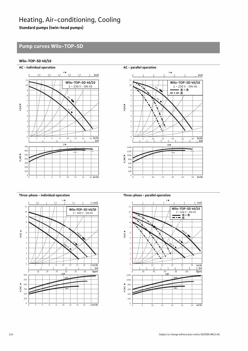
214 Subject to change without prior notice 09/2006 WILO AG
Heating, Air-conditioning, CoolingStandard pumps (twin-head pumps)
Pump curves Wilo-TOP-SD
Wilo-TOP-SD 40/10
AC - individual operation AC - parallel operation
Three-phase - individual operation Three-phase - parallel operation
0
1
2
3
4
5
6
7
8
9
10
11
0
100
200
300
400
500
600
700
0 2 4 6 8 10 12 14 16
0 2 4 6 8 10 12 14 160 1 2 3 4
0 0,5 1,0 1,5 2,0 2,5 3
v
Wilo-TOP-SD 40/101 ~ 230 V - DN 40
Q
max.
min.max.
[m3/h]
[m3/h]
[m/s]
[l/s]
H [m
]P 1
[W]
min.
0
1
2
3
4
5
6
7
8
9
10
11
0
200
400
600
800
1000
1200
1400
0 5 10 15 20 25 30
0 5 10 15 20 25 300 1 2 3 4 5 6 7 8
0 1 2 3 4 5
v
Q
max.
min.
min.max.
[m3/h]
[m3/h]
[m/s]
[l/s]
H [m
]P 1
[W]
Wilo-TOP-SD 40/101 ~ 230 V - DN 40
+
0 1 2 3 4 5
0 10 20 30 40 50 60
0 0,5 1 1,5 2 2,5 3 3,5
0 2 4 6 8 10 12 14 16 18
v [m/s]
Q[lgpm]
600
500
400
300
200
100
0
11
10
9
8
7
6
5
4
3
2
1
0
[l/s]
max.
Wilo-TOP-SD 40/103 ~ 400 V - DN 40
max. (1 )
(2 )min. (3 )
min.
0 2 4 6 8 10 12 14 16 18
P1 [
W]
H [m
]
[m3/h]
[m3/h]
1200
1000
800
600
400
200
0
0 1 2 3 4 5 6 7 8 9
0 20 40 60 80 100
0 1 2 3 4 5 6
0 5 10 15 20 25 30
v [m/s]
Q[lgpm]
11
10
9
8
7
6
5
4
3
2
1
0
[l/s]
min.
max.
(2 )
0 5 10 15 20 25 30
Wilo-TOP-SD 40/10 3 ~ 400 V - DN 40
max. (1 )
min. (3 )
P1 [
W]
H [m
]
[m3/h]
[m3/h]
+
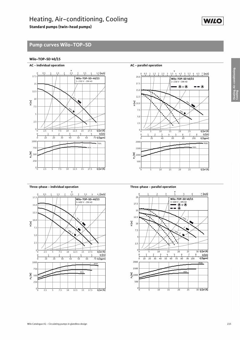
215
Heating, Air-conditioning, CoolingStandard pumps (twin-head pumps)
Pump curves Wilo-TOP-SD
Wilo Catalogue A1 - Circulating pumps in glandless design
Hea
tin
g, A
ir-c
on
dit
ion
ing
, C
oo
ling
Po
tab
le w
ater
cir
cula
tio
nSo
lar
ther
mal
Serv
ice/
Acc
esso
ries
, Sys
tem
sSw
itch
gea
rs a
nd
Co
ntr
ol
Dev
ices
P
um
p M
anag
emen
t S y
stem
s
Wilo-TOP-SD 40/15
AC - individual operation AC - parallel operation
Three-phase - individual operation Three-phase - parallel operation
0 0,5 1 1,5 2,52 3 3,5 4,54 [m/s]v
0
2,5
5
7,5
10
12,5
15
17,5
2,5 7,5 12,5 17,5 Q [m³/h]
H [m
]
0 1 2 3 4 5 Q [l/s]
0 10 20 30 40 50 60 70 Q [Igpm]
0
250
500
750
1000
2,5 7,5 12,5
0 5 10 15
0 5 10 15 17,5 Q [m³/h]
P 1 [W
]
max.
min.
max.
min.
Wilo-TOP-SD-40/151~230 V - DN 40
0 0,5 1 1,5 2 2,5 3 3,5
v4 4,5 5 5,5 6 76,5 [m/s]
0
2,5
5,0
7,5
10,0
12,5
15,0
17,5
20,0
0 5 10 15 20 25 Q [m³/h]H
[m]
0 1 2 3 4 5 6 7 8 Q [l/s]
0 20 40 60 80 100 Q [Igpm]
0
500
1000
1500
2000
0 5 10 15 20 25 Q [m³/h]
P 1 [W
]
+
Wilo-TOP-SD 40/151~230 V - DN 40
max.
min.
max.
min.
0 0,5 1 1,5 2 2,5 3 3,5 4,54 [m/s]
0
2,5
5,0
7,5
10,0
12,5
15,0
17,5
2,5 7,5 12,5 17,5 Q [m³/h]
H [m
]
0 1 2 3 4 5 Q [l/s]
0 10 20 30 40 50 60 70 Q [Igpm]
0
250
500
750
1000
2,5 7,5 12,5
0 5 10 15
0 5 10 15 17,5 Q [m³/h]
P 1 [W
]
v
max.
min.
max. 1
min. 3
2
Wilo-TOP-SD-40/153~400 V - DN 40
H [m
]P 1
[W]
[m/s]
00
0 1 2 3
0 10 20 30 40 50 60 70 80 90 100
4 5 6 7 8
5 10 15 20 25 30 Q [m³/h]
0 5 10 15 20 25 30 Q [m³/h]
Q [l/s]Q [lgpm]
2,5
5
7,5
0
500
1000
1500
2000
10
12,5
15
17,5
20Wilo-TOP-SD 40/153~400 V - DN 40
max.
min.
max. 1
min. 3
2
v0 1 2 3 4 5 6 7
+
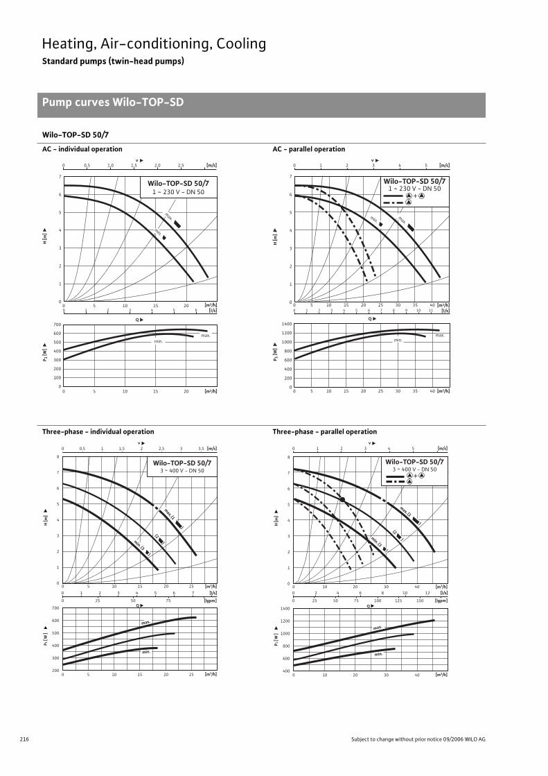
216 Subject to change without prior notice 09/2006 WILO AG
Heating, Air-conditioning, CoolingStandard pumps (twin-head pumps)
Pump curves Wilo-TOP-SD
Wilo-TOP-SD 50/7
AC - individual operation AC - parallel operation
Three-phase - individual operation Three-phase - parallel operation
0
1
2
3
4
5
6
7
0
100
200
300
400
500
600
700
0 5 10 15 20
0 5 10 15 200 1 2 3 4 5 6
0 0,5 1,0 1,5 2,0 2,5
v
Wilo-TOP-SD 50/71 ~ 230 V - DN 50
Q
max.
min.
min.min.min.min.min.min.min.min.min.min.min.min.min.
max.max.max.max.max.
[m3/h]
[m3/h]
[m/s]
[l/s]
H [m
]P 1
[W]
0
1
2
3
4
5
6
7
0 5 10 15 20 25 30 35 400 1 2 3 4 5 6 7 8 9 10 11
0 1 2 3 4 5
v
max.
min.
[m3/h]
0
200
400
600
800
1000
1200
1400
0 5 10 15 20 25 30 35 40
Q
min.max.
[m3/h]
[m/s]
[l/s]
H [m
]P 1
[W]
Wilo-TOP-SD 50/71 ~ 230 V - DN 50
+
0 1 2 3 4 5 6 7
0 25 50 75
0 0,5 1 1,5 2 2,5 3 3,5
0 5 10 15 20 25
v [m/s]
Q[lgpm]
700
600
500
400
300
200
8
7
6
5
4
3
2
1
0
[l/s]
0 5 10 15 20 25
min.
max.
min. (3 )
max. (1 )
(2 )
P1 [
W]
H [m
]
[m3/h]
[m3/h]
Wilo-TOP-SD 50/73 ~ 400 V - DN 50
1400
1200
1000
800
600
400
0 2 4 6 8 10 12
0 25 50 75 100 125 150
0 1 2 3 4 5
0 10 20 30 40
v [m/s]
Q[lgpm]
8
7
6
5
4
3
2
1
0
[l/s]
(2 )
0 10 20 30 40
min. (3 )
max. (1 )
max.
min.
P1 [
W]
H [m
]
[m3/h]
[m3/h]
+
Wilo-TOP-SD 50/73 ~ 400 V - DN 50
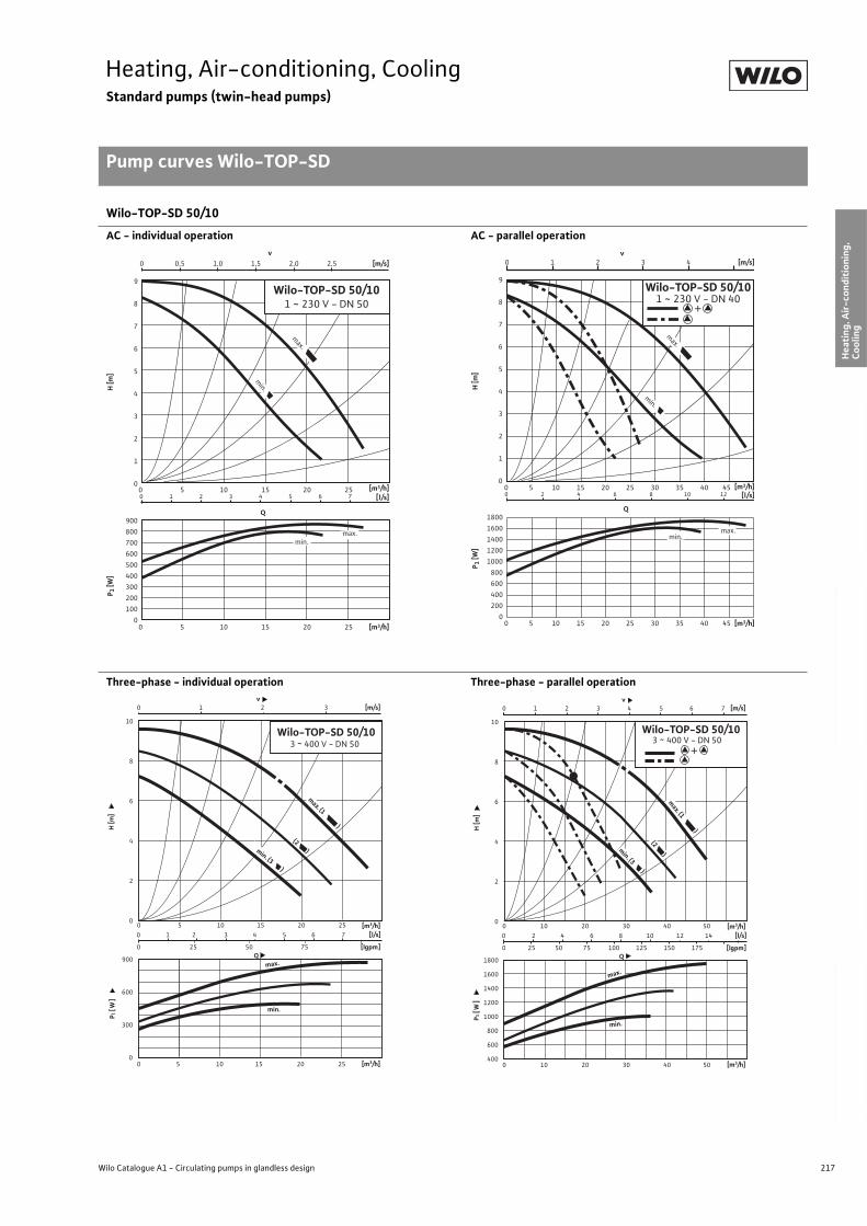
217
Heating, Air-conditioning, CoolingStandard pumps (twin-head pumps)
Pump curves Wilo-TOP-SD
Wilo Catalogue A1 - Circulating pumps in glandless design
Hea
tin
g, A
ir-c
on
dit
ion
ing
, C
oo
ling
Po
tab
le w
ater
cir
cula
tio
nSo
lar
ther
mal
Serv
ice/
Acc
esso
ries
, Sys
tem
sSw
itch
gea
rs a
nd
Co
ntr
ol
Dev
ices
P
um
p M
anag
emen
t S y
stem
s
Wilo-TOP-SD 50/10
AC - individual operation AC - parallel operation
Three-phase - individual operation Three-phase - parallel operation
0
1
2
3
4
5
6
7
8
9
0
100
200
300
400
500
600
700
800
900
0 5 10 15 20 25
0 5 10 15 20 250 1 2 3 4 5 6 7
0 0,5 1,0 1,5 2,0 2,5
v
Wilo-TOP-SD 50/101 ~ 230 V - DN 50
Q
max.
min.
min.
max.
[m3/h]
[m3/h]
[m/s]
[l/s]
H [m
]P 1
[W]
0
1
2
3
4
5
6
7
8
9
0
200
400
600
800
1000
1200
1400
1600
1800
0 5 10 15 20 25 30 35 40 45
0 5 10 15 20 25 30 35 40 45
0 2 4 6 8 10 12
0 1 2 3 4
v
Q
max.
min.
min.max.
[m3/h]
[m3/h]
[m/s]
[l/s]
H [m
]P 1
[W]
Wilo-TOP-SD 50/101 ~ 230 V - DN 40
+
0 1 2 3 4 5 6 7
0 25 50 75
0 1 2 3
0 5 10 15 20 25
0 5 10 15 20 25
v [m/s]
Q[lgpm]
900
600
300
0
10
8
6
4
2
0
[l/s]
min.
max.
(2 )
Wilo-TOP-SD 50/103 ~ 400 V - DN 50
min. (3 )
max. (1 )
P1 [
W]
H [m
]
[m3/h]
[m3/h]
1800
1600
1400
1200
1000
800
600
400
0 2 4 6 8 10 12 14
0 25 50 75 100 125 150 175
0 1 2 3 4 5 6 7
0 10 20 30 40 50
v [m/s]
Q[lgpm]
10
8
6
4
2
0
[l/s]
min.
Wilo-TOP-SD 50/10 3 ~ 400 V - DN 50
0 10 20 30 40 50
max.
min. (3 )(2 )
max. (1
)
P1 [
W]
H [m
]
[m3/h]
[m3/h]
+
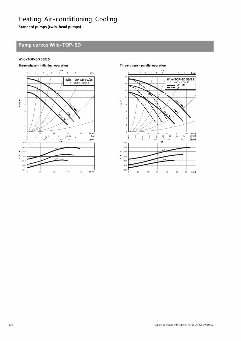
218 Subject to change without prior notice 09/2006 WILO AG
Heating, Air-conditioning, CoolingStandard pumps (twin-head pumps)
Pump curves Wilo-TOP-SD
Wilo-TOP-SD 50/15
Three-phase - individual operation Three-phase - parallel operation
0 10 20 30 40
v [m/s]
Q1800
1600
1400
1200
1000
800
600
min.
16
14
12
10
8
6
4
2
0
(2 )
0 10 20 30 40
0 2 4 6 8 10 12
0 50 100 150 [lgpm]
[l/s]
0 1 2 3 4 5 6
max. (1 )
min. (3 )
max.
Wilo-TOP-SD 50/153 ~ 400 V - DN 50
P1 [
W]
H [m
]
[m3/h]
[m3/h]
0 10 20 30 40 50 60
0 10 20 30 40 50 60
v [m/s]
Q
0 2 4 6 8 10 12 14 16 18
0 50 100 150 200 [lgpm]
[l/s]
min.
max.
3600
3200
2800
2400
2000
1600
1200
0 1 2 3 4 5 6 7 8
16
14
12
10
8
6
4
2
0
max. (1 )
(2 )min. (3 )
Wilo-TOP-SD 50/15 3 ~ 400 V - DN 50
P1 [
W]
H [m
]
[m3/h]
[m3/h]
+
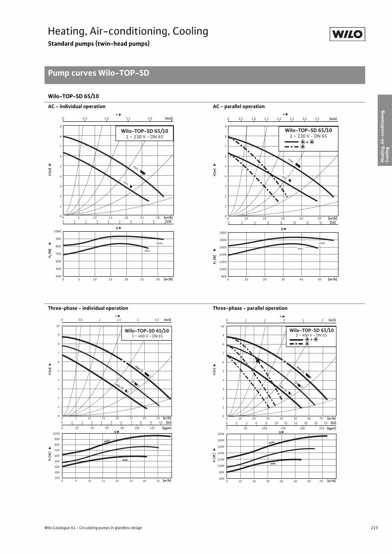
219
Heating, Air-conditioning, CoolingStandard pumps (twin-head pumps)
Pump curves Wilo-TOP-SD
Wilo Catalogue A1 - Circulating pumps in glandless design
Hea
tin
g, A
ir-c
on
dit
ion
ing
, C
oo
ling
Po
tab
le w
ater
cir
cula
tio
nSo
lar
ther
mal
Serv
ice/
Acc
esso
ries
, Sys
tem
sSw
itch
gea
rs a
nd
Co
ntr
ol
Dev
ices
P
um
p M
anag
emen
t S y
stem
s
Wilo-TOP-SD 65/10
AC - individual operation AC - parallel operation
Three-phase - individual operation Three-phase - parallel operation
400
500
600
700
800
900
1000
0
1
2
3
4
5
6
7
8
9
0 5 10 15 20 25 30
0 5 10 15 20 25 300 1 2 3 4 5 6 7 8
0 0.5 1.0 1.5 2.0
v
Wilo-TOP-SD 65/101 ~ 230 V - DN 65
Q
max.
min.
min.
max.
[m3/h]
[m3/h]
[m/s]
[l/s]
H [m
]P 1
[W]
0
1
2
3
4
5
6
7
8
9
800
1000
1200
1400
1600
1800
2000
0 10 20 30 40 50
0 10 20 30 40 50
0 2 4 6 8 10 12 14
0 0.5 1.0 1.5 2.0 2.5 3.0 3.5
v
Wilo-TOP-SD 65/101 ~ 230 V - DN 65
Q
max.
min.
min.
max.
[m3/h]
[m3/h]
[m/s]
[l/s]
H [m
]P 1
[W]
+
0 1 2 3 4 5 6 7 8 9 10
0 20 40 60 80 100 120
0 0,5 1 1,5 2 2,5
0 5 10 15 20 25 30 35
0 5 10 15 20 25 30 35
v [m/s]
Q[lgpm]
1000
900
800
700
600
500
400
300
200
10
9
8
7
6
5
4
3
2
1
0
[l/s]
min.
max.
(2 )
max. (1 )
min. (3 )
Wilo-TOP-SD 65/103 ~ 400 V - DN 65
P1 [
W]
H [m
]
[m3/h]
[m3/h]
2000
1800
1600
1400
1200
1000
800
600
0 2 4 6 8 10 12 14 16 18 19
0 50 100 150 200 250
0 1 2 3 4 5
0 10 20 30 40 50 60 70
v [m/s]
Q[lgpm]
10
9
8
7
6
5
4
3
2
1
0
[l/s]
min.
max.
0 10 20 30 40 50 60 70
Wilo-TOP-SD 65/10 3 ~ 400 V - DN 65
max. (1 )(2 )min. (3 )
P1 [
W]
H [m
]
[m3/h]
[m3/h]
+
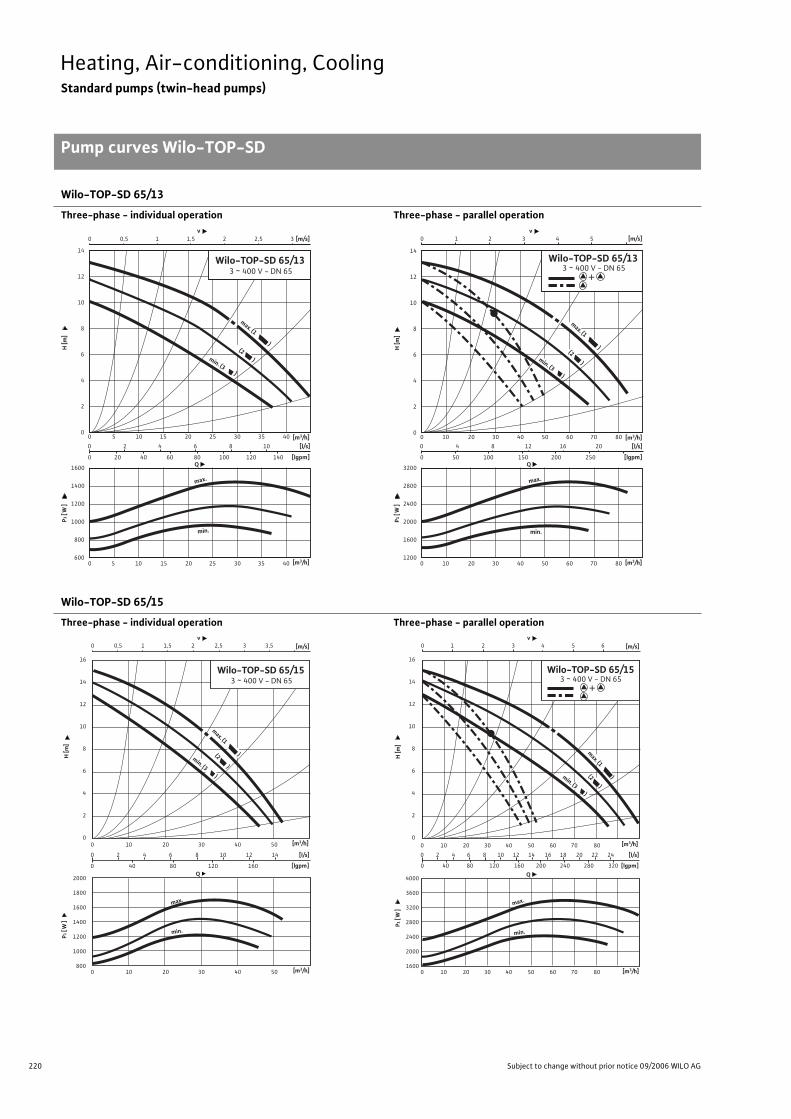
220 Subject to change without prior notice 09/2006 WILO AG
Heating, Air-conditioning, CoolingStandard pumps (twin-head pumps)
Pump curves Wilo-TOP-SD
Wilo-TOP-SD 65/13
Three-phase - individual operation Three-phase - parallel operation
Wilo-TOP-SD 65/15
Three-phase - individual operation Three-phase - parallel operation
0 2 4 6 8 10
0 20 40 60 80 100 120 140
0 0,5 1 1,5 2 2,5 3
0 5 10 15 20 25 30 35 40
0 5 10 15 20 25 30 35 40
v [m/s]
Q[lgpm]
1600
1400
1200
1000
800
600
14
12
10
8
6
4
2
0
[l/s]
min.
max.
min. (3 )
Wilo-TOP-SD 65/133 ~ 400 V - DN 65
max. (1 )(2 )
P1 [
W]
H [m
]
[m3/h]
[m3/h]
3200
2800
2400
2000
1600
1200
0 4 8 12 16 20
0 50 100 150 200 250
0 1 2 3 4 5
0 10 20 30 40 50 60 70 80
0 10 20 30 40 50 60 70 80
v [m/s]
Q[lgpm]
14
12
10
8
6
4
2
0
[l/s]
min.
max.
(2 )
Wilo-TOP-SD 65/13 3 ~ 400 V - DN 65
min. (3 )
max. (1 )
P1 [
W]
H [m
]
[m3/h]
[m3/h]
+
2000
1800
1600
1400
1200
1000
800
16
14
12
10
8
6
4
2
0
v0 0,5 1 1,5 2 2,5 3 3,5
0 2 4 6 8 10 12 14
0 40 80 120 160 [lgpm]
[l/s]
0 10 20 30 40 50
Q
[m/s]
min.
max.
(2 )
max. (1 )
min. (3 )
0 10 20 30 40 50
Wilo-TOP-SD 65/153 ~ 400 V - DN 65
P1 [
W]
H [m
]
[m3/h]
[m3/h]
4000
3600
3200
2800
2400
2000
1600
16
14
12
10
8
6
4
2
0
0 2 4 6 8 10 12 14 16 18 20 22 24
0 40 80 120 160 200 240 280 320 [lgpm]
[l/s]
0 10 20 30 40 50 60 70 80
Q
min.
max.
max. (1 )(2 )
min. (3 )
v0 1 2 3 4 5 6 [m/s]
0 10 20 30 40 50 60 70 80
Wilo-TOP-SD 65/15 3 ~ 400 V - DN 65
P1 [
W]
H [m
]
[m3/h]
[m3/h]
+
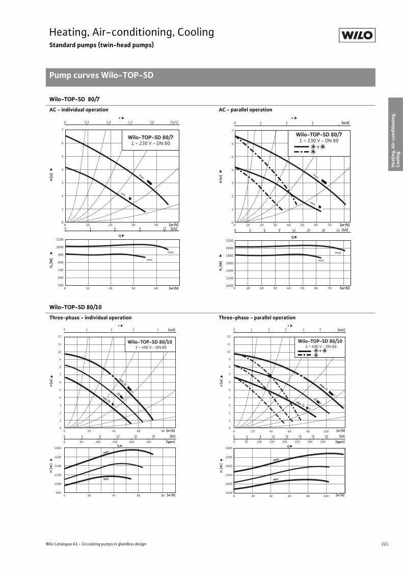
221
Heating, Air-conditioning, CoolingStandard pumps (twin-head pumps)
Pump curves Wilo-TOP-SD
Wilo Catalogue A1 - Circulating pumps in glandless design
Hea
tin
g, A
ir-c
on
dit
ion
ing
, C
oo
ling
Po
tab
le w
ater
cir
cula
tio
nSo
lar
ther
mal
Serv
ice/
Acc
esso
ries
, Sys
tem
sSw
itch
gea
rs a
nd
Co
ntr
ol
Dev
ices
P
um
p M
anag
emen
t S y
stem
s
Wilo-TOP-SD 80/7
AC - individual operation AC - parallel operation
Wilo-TOP-SD 80/10
Three-phase - individual operation Three-phase - parallel operation
0
1
2
3
4
5
6
7
500
600
700
800
900
1000
1100
0 10 20 30 40
0 10 20 30 400 3 6 9 12
0 0.5 1.0 1.5 2.0
v
Q
Wilo-TOP-SD 80/71 ~ 230 V - DN 80
min.
max.
[m3/h]
[m3/h]
[m/s]
[l/s]
H [m
]P 1
[W]
max.
min.
0
1
2
3
4
5
6
7
1000
1200
1400
1600
1800
2000
2200
0 10 20 30 40 50 60 70
0 10 20 30 40 50 60 70
0 3 6 9 12 15 18 21
0 1 2 3
v
Q
[m3/h]
[m3/h]
[m/s]
[l/s]
H [m
]P 1
[W]
min.
max.
+
Wilo-TOP-SD 80/71 ~ 230 V - DN 80
max.
min.
1800
1600
1400
1200
1000
800
12
11
10
9
8
7
6
5
4
3
2
1
0
v0 1 2 3 4
0 4 8 12 16 20
0 50 100 150 200 250 [lgpm]
[l/s]
0 20 40 60 80
Q
[m/s]
min.
max.
(2 )
max. (1 )
Wilo-TOP-SD 80/103 ~ 400 V - DN 80
0 20 40 60 80
min. (3 )
P1 [
W]
H [m
]
[m3/h]
[m3/h]
3600
3200
2800
2400
2000
1600
0 4 8 12 16 20 24 28
0 50 100 150 200 250 300 350 [lgpm]
[l/s]
0 20 40 60 80 100
Q
min.
max.
v0 1 2 3 4 5 [m/s]
12
11
10
9
8
7
6
5
4
3
2
1
0
Wilo-TOP-SD 80/10 3 ~ 400 V - DN 80
max. (1 )(2 )min. (3 )
0 20 40 60 80 100
P1 [
W]
H [m
]
[m3/h]
[m3/h]
+
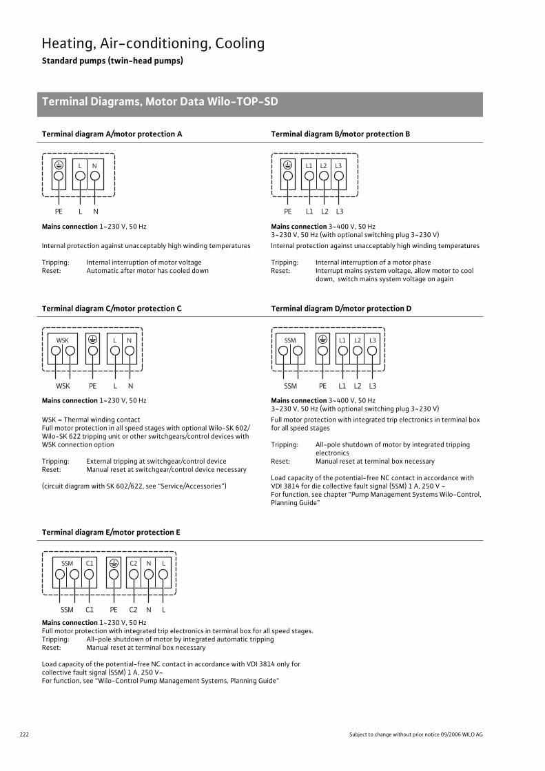
222 Subject to change without prior notice 09/2006 WILO AG
Heating, Air-conditioning, CoolingStandard pumps (twin-head pumps)
Terminal Diagrams, Motor Data Wilo-TOP-SD
Terminal diagram A/motor protection A Terminal diagram B/motor protection B
Mains connection 1~230 V, 50 Hz Mains connection 3~400 V, 50 Hz3~230 V, 50 Hz (with optional switching plug 3~230 V)
Internal protection against unacceptably high winding temperatures
Tripping: Internal interruption of motor voltageReset: Automatic after motor has cooled down
Internal protection against unacceptably high winding temperatures
Tripping: Internal interruption of a motor phaseReset: Interrupt mains system voltage, allow motor to cool
down, switch mains system voltage on again
Terminal diagram C/motor protection C Terminal diagram D/motor protection D
Mains connection 1~230 V, 50 Hz Mains connection 3~400 V, 50 Hz3~230 V, 50 Hz (with optional switching plug 3~230 V)
WSK = Thermal winding contactFull motor protection in all speed stages with optional Wilo-SK 602/Wilo-SK 622 tripping unit or other switchgears/control devices with WSK connection option
Tripping: External tripping at switchgear/control deviceReset: Manual reset at switchgear/control device necessary
(circuit diagram with SK 602/622, see “Service/Accessories”)
Full motor protection with integrated trip electronics in terminal box for all speed stages
Tripping: All-pole shutdown of motor by integrated tripping electronics
Reset: Manual reset at terminal box necessary
Load capacity of the potential-free NC contact in accordance with VDI 3814 for die collective fault signal (SSM) 1 A, 250 V ~For function, see chapter “Pump Management Systems Wilo-Control, Planning Guide”
Terminal diagram E/motor protection E
Mains connection 1~230 V, 50 HzFull motor protection with integrated trip electronics in terminal box for all speed stages.Tripping: All-pole shutdown of motor by integrated automatic trippingReset: Manual reset at terminal box necessary
Load capacity of the potential-free NC contact in accordance with VDI 3814 only for collective fault signal (SSM) 1 A, 250 V~For function, see “Wilo-Control Pump Management Systems, Planning Guide“
L NPE
NL
L1 L2PE
L2
L3
L3L1
L NPE
NL
WSK
WSK
L1 L2 L3PE
L1 L2 L3
SSM
SSM
C2 N LPEC1
C1SSM LC2 N
SSM
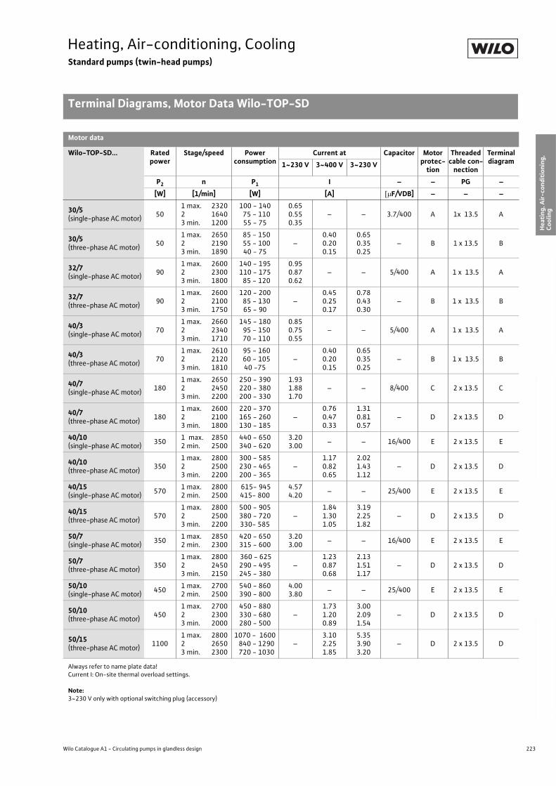
223
Heating, Air-conditioning, CoolingStandard pumps (twin-head pumps)
Terminal Diagrams, Motor Data Wilo-TOP-SD
Wilo Catalogue A1 - Circulating pumps in glandless design
Hea
tin
g, A
ir-c
on
dit
ion
ing
, C
oo
ling
Po
tab
le w
ater
cir
cula
tio
nSo
lar
ther
mal
Serv
ice/
Acc
esso
ries
, Sys
tem
sSw
itch
gea
rs a
nd
Co
ntr
ol
Dev
ices
P
um
p M
anag
emen
t S y
stem
s
Motor data
Wilo-TOP-SD... Rated power
Stage/speed Power consumption
Current at Capacitor Motor protec-
tion
Threaded cable con-
nection
Terminal diagram1~230 V 3~400 V 3~230 V
P2 n P1 I – – PG –
[W] [1/min] [W] [A] F/VDB] – – –
30/5(single-phase AC motor)
501 max. 2320 2 16403 min. 1200
100 - 140 75 - 110
55 - 75
0.650.550.35
– – 3.7/400 A 1x 13.5 A
30/5(three-phase AC motor)
501 max. 2650 2 21903 min. 1890
85 - 150 55 - 100
40 - 75–
0.400.200.15
0.650.350.25
– B 1 x 13.5 B
32/7(single-phase AC motor)
901 max. 2600 2 23003 min. 1800
140 - 195110 - 175 85 - 120
0.950.870.62
– – 5/400 A 1 x 13.5 A
32/7(three-phase AC motor)
901 max. 2600 2 21003 min. 1750
120 - 200 85 - 130
65 - 90–
0.450.250.17
0.780.430.30
– B 1 x 13.5 B
40/3(single-phase AC motor)
701 max. 2660 2 23403 min. 1710
145 - 180 95 - 150 70 - 110
0.850.750.55
– – 5/400 A 1 x 13.5 A
40/3(three-phase AC motor)
701 max. 2610 2 21203 min. 1810
95 - 160 60 - 105
40 -75–
0.400.200.15
0.650.350.25
– B 1 x 13.5 B
40/7(single-phase AC motor)
1801 max. 2650 2 24503 min. 2200
250 - 390220 - 380200 - 330
1.931.881.70
– – 8/400 C 2 x 13.5 C
40/7(three-phase AC motor)
1801 max. 2600 2 21003 min. 1800
220 - 370165 - 260130 - 185
–0.760.470.33
1.310.810.57
– D 2 x 13.5 D
40/10(single-phase AC motor)
3501 max. 2850 2 min. 2500
440 - 650340 - 620
3.203.00
– – 16/400 E 2 x 13.5 E
40/10(three-phase AC motor)
3501 max. 2800 2 25003 min. 2200
300 - 585230 - 465200 - 365
–1.170.820.65
2.021.431.12
– D 2 x 13.5 D
40/15(single-phase AC motor)
5701 max. 2800 2 min. 2500
615- 945415- 800
4.574.20
– – 25/400 E 2 x 13.5 E
40/15(three-phase AC motor)
5701 max. 2800 2 25003 min. 2200
500 - 905380 - 720330- 585
–1.841.301.05
3.192.251.82
– D 2 x 13.5 D
50/7(single-phase AC motor)
3501 max. 2850 2 min. 2300
420 - 650315 - 600
3.203.00
– – 16/400 E 2 x 13.5 E
50/7(three-phase AC motor)
3501 max. 2800 2 24503 min. 2150
360 - 625290 - 495245 - 380
–1.230.870.68
2.131.511.17
– D 2 x 13.5 D
50/10(single-phase AC motor)
4501 max. 2700 2 min. 2500
540 - 860390 - 800
4.003.80
– – 25/400 E 2 x 13.5 E
50/10(three-phase AC motor)
4501 max. 2700 2 23003 min. 2000
450 - 880330 - 680280 - 500
–1.731.200.89
3.002.091.54
– D 2 x 13.5 D
50/15(three-phase AC motor)
11001 max. 2800 2 26503 min. 2300
1070 - 1600 840 - 1290 720 - 1030
–3.102.251.85
5.353.903.20
– D 2 x 13.5 D
Always refer to name plate data!Current I: On-site thermal overload settings.
Note:3~230 V only with optional switching plug (accessory)
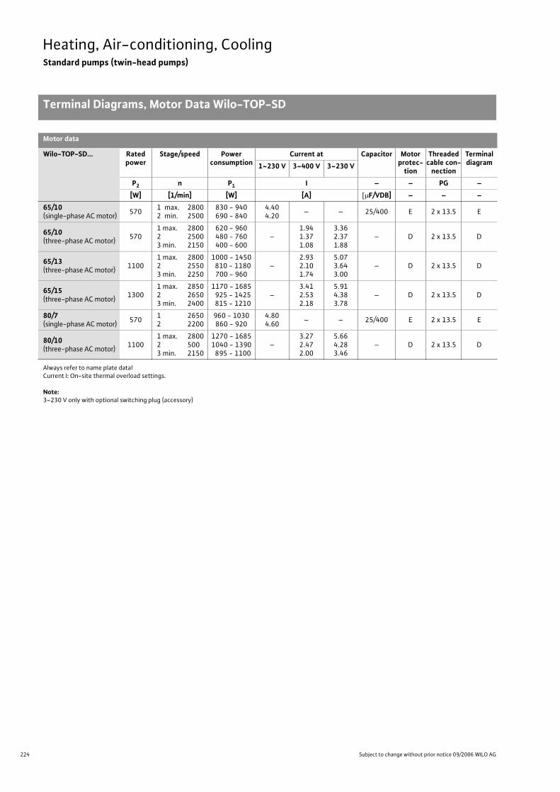
224 Subject to change without prior notice 09/2006 WILO AG
Heating, Air-conditioning, CoolingStandard pumps (twin-head pumps)
Terminal Diagrams, Motor Data Wilo-TOP-SD
65/10(single-phase AC motor)
5701 max. 2800 2 min. 2500
830 - 940690 - 840
4.404.20
– – 25/400 E 2 x 13.5 E
65/10(three-phase AC motor)
5701 max. 2800 2 25003 min. 2150
620 - 960480 - 760400 - 600
–1.941.371.08
3.362.371.88
– D 2 x 13.5 D
65/13(three-phase AC motor)
11001 max. 2800 2 25503 min. 2250
1000 - 1450 810 - 1180
700 - 960–
2.932.101.74
5.073.643.00
– D 2 x 13.5 D
65/15(three-phase AC motor)
13001 max. 2850 2 26503 min. 2400
1170 - 1685 925 - 1425 815 - 1210
–3.412.532.18
5.914.383.78
– D 2 x 13.5 D
80/7(single-phase AC motor)
5701 2650 2 2200
960 - 1030860 - 920
4.804.60
– – 25/400 E 2 x 13.5 E
80/10(three-phase AC motor)
11001 max. 2800 2 5003 min. 2150
1270 - 16851040 - 1390 895 - 1100
–3.272.472.00
5.664.283.46
– D 2 x 13.5 D
Motor data
Wilo-TOP-SD... Rated power
Stage/speed Power consumption
Current at Capacitor Motor protec-
tion
Threaded cable con-
nection
Terminal diagram1~230 V 3~400 V 3~230 V
P2 n P1 I – – PG –
[W] [1/min] [W] [A] F/VDB] – – –
Always refer to name plate data!Current I: On-site thermal overload settings.
Note:3~230 V only with optional switching plug (accessory)
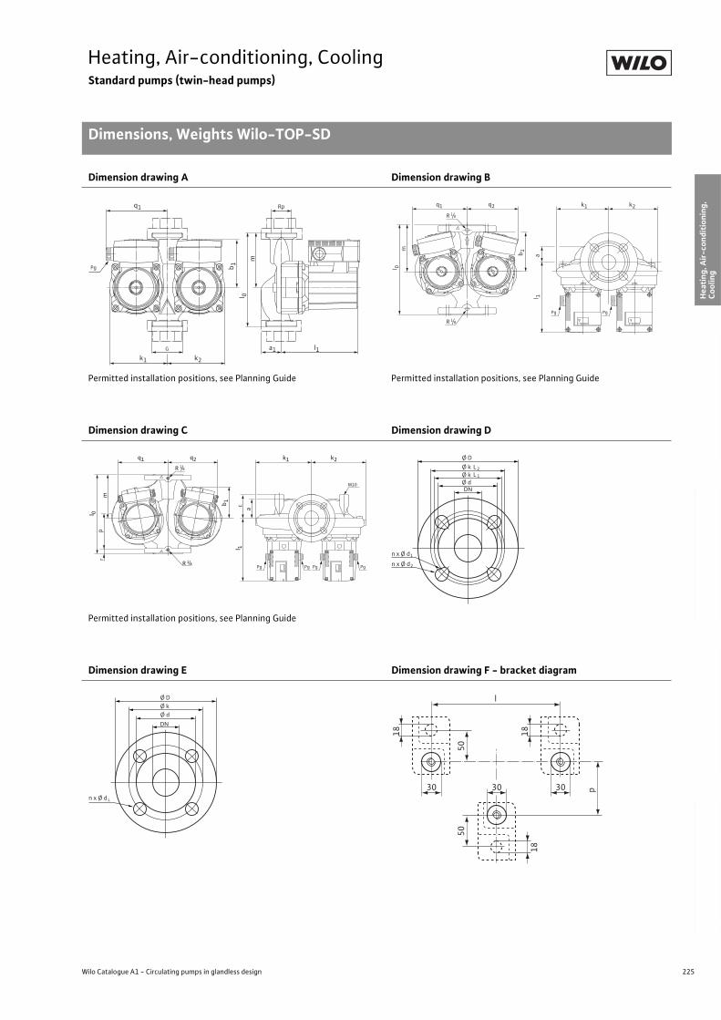
225
Heating, Air-conditioning, CoolingStandard pumps (twin-head pumps)
Dimensions, Weights Wilo-TOP-SD
Wilo Catalogue A1 - Circulating pumps in glandless design
Hea
tin
g, A
ir-c
on
dit
ion
ing
, C
oo
ling
Po
tab
le w
ater
cir
cula
tio
nSo
lar
ther
mal
Serv
ice/
Acc
esso
ries
, Sys
tem
sSw
itch
gea
rs a
nd
Co
ntr
ol
Dev
ices
P
um
p M
anag
emen
t S y
stem
s
Dimension drawing A Dimension drawing B
Permitted installation positions, see Planning Guide Permitted installation positions, see Planning Guide
Dimension drawing C Dimension drawing D
Permitted installation positions, see Planning Guide
Dimension drawing E Dimension drawing F - bracket diagram
Rp
Pg
m
G
l 0
l1a1k2k1
q1
b 1
l 1
ml 0
Pg Pg
a
k2k1q1 q2
R 1/8
R 1/8
b 1
c
rp
Pg PgPg Pg
M10
l 1
m
l 0
a
k2k1q1 q2
R 1/8
R 1/8
b 1
Ø D
n x Ø d
Ø k
DN
L2
Ø k Ø d
L 1
1
n x Ø d 2
n x Ø d
Ø D Ø k
DN
Ø d
L
l
50
p
50
18
18 18
303030
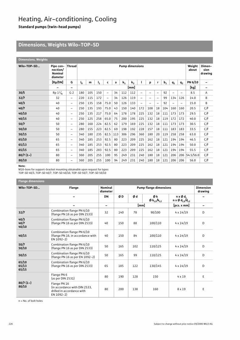
226 Subject to change without prior notice 09/2006 WILO AG
Heating, Air-conditioning, CoolingStandard pumps (twin-head pumps)
Dimensions, Weights Wilo-TOP-SD
Note:M10-bore for support-bracket mounting obtainable upon request for types TOP-SD 40/3, TOP-SD 40/7, TOP-SD 40/10, TOP-SD 50/7, TOP-SD 50/10
Dimensions, Weights
Wilo-TOP-SD... Pipe con-nection/Nominaldiameter
Thread Pump dimensions Weightabout
Dimen-sion
drawing
[Rp/DN] G I0 m l1 c a k1 k2 l p r b1 q1 q2 PN 6/10 –
– – [mm] [kg] –
30/5 Rp 11/4 G 2 180 105 150 – 34 112 112 – – – 92 – – 8.5 A
32/7 32 – 220 115 172 – 34 126 119 – – – 99 134 126 14.0 B
40/3 40 – 250 135 158 75.0 50 126 133 – – – 92 – – 15.0 B
40/7 40 – 250 135 193 75.0 43 150 140 172 108 18 104 160 160 20.5 C/F
40/10 40 – 250 135 217 75.0 64 178 178 225 132 18 111 173 173 29.5 C/F
40/15 40 – 250 125 258 65.0 75 200 195 225 132 18 119 172 172 40.0 C/F
50/7 50 – 280 160 224 82.5 62 179 169 225 132 18 111 173 173 30.5 C/F
50/10 50 – 280 155 223 82.5 69 198 192 228 157 18 111 183 183 33.5 C/F
50/15 50 – 340 180 235 82.5 113 306 296 360 180 20 119 258 258 63.0 C/F
65/10 65 – 340 185 253 92.5 80 223 209 225 162 18 121 194 194 46.5 C/F
65/13 65 – 340 185 253 92.5 80 223 209 225 162 18 121 194 194 50.0 C/F
65/15 65 – 340 185 283 92.5 80 223 209 225 162 18 121 194 194 55.5 C/F
80/7 (1~) 80 – 360 205 255 100 95 249 231 240 180 18 121 206 206 54.5/56.0 C/F
80/10 80 – 360 205 255 100 94 249 231 240 180 18 121 206 206 56.0 C/F
Flange dimensions
Wilo-TOP-SD... Flange Nominal diameter
Pump flange dimensions Dimension drawing
– DN Ø D Ø d Ø kØ kL1/kL2
n x Ø dLn x Ø dL1/dL2
–
– – [mm] [pcs. x mm] –
32/7Combination flange PN 6/10(flange PN 16 as per DIN 2533)
32 140 78 90/100 4 x 14/19 D
40/340/740/10
Combination flange PN 6/10(flange PN 16 as per DIN 2533) 40 150 88 100/110 4 x 14/19 D
40/15Combination flange PN 6/10(flange PN 16, in accordance with EN 1092-2)
40 150 84 100/110 4 x 14/19 D
50/750/10
Combination flange PN 6/10(flange PN 16 as per DIN 2533)
50 165 102 110/125 4 x 14/19 D
50/15Combination flange PN 6/10(flange PN 16 as per EN 1092-2)
50 165 99 110/125 4 x 14/19 D
65/1065/1365/15
Combination flange PN 6/10(flange PN 16 as per DIN 2533) 65 185 122 130/145 4 x 14/19 D
80/7 (1~)80/10
Flange PN 6 (as per DIN 2531)
80 190 128 150 4 x 19 E
Flange PN 16(in accordance with DIN 2533,drilled in accordance with EN 1092-2)
80 200 138 160 8 x 19 E
n = No. of bolt holes

227
Heating, Air-conditioning, CoolingStandard pumps (twin-head pumps)
Wilo Catalogue A1 - Circulating pumps in glandless design
Hea
tin
g, A
ir-c
on
dit
ion
ing
, C
oo
ling
Po
tab
le w
ater
cir
cula
tio
nSo
lar
ther
mal
Serv
ice/
Acc
esso
ries
, Sys
tem
sSw
itch
gea
rs a
nd
Co
ntr
ol
Dev
ices
P
um
p M
anag
emen
t S y
stem
s
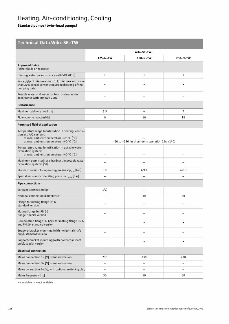
228 Subject to change without prior notice 09/2006 WILO AG
Heating, Air-conditioning, CoolingStandard pumps (twin-head pumps)
Technical Data Wilo-SE-TW
Wilo-SE-TW...
125-N-TW 150-N-TW 200-N-TW
Approved fluids(other fluids on request)
Heating water (In accordance with VDI 2035) • • •
Water/glycol mixtures (max. 1:1; mixtures with more than 20% glycol content require rechecking of the pumping data)
• • •
Potable water and water for food businesses in accordance with TrinkwV 2001
– – –
Performance
Maximum delivery head [m] 5.5 4 7
Flow volume max. [m3/h] 9 16 18
Permitted field of application
Temperature range for utilisation in heating, ventila-tion and A/C systems
at max. ambient temperature +25 °C [°C]at max. ambient temperature +40 °C [°C]
–-20 to +130 (in short-term operation 2 h: +140)
Temperature range for utilisation in potable water circulation systems
at max. ambient temperature +40 °C [°C] – – –
Maximum permitted total hardness in potable water circulation systems [°d]
– – –
Standard version for operating pressure pmax [bar] 10 6/10 6/10
Special version for operating pressure pmax [bar] – – –
Pipe connections
Screwed connection Rp 11/4 – –
Nominal connection diameter DN – 40 40
Flange for mating flange PN 6, standard version
– – –
Mating flange for PN 16 flange, special version
– – –
Combination flange PN 6/10 for mating flange PN 6 and PN 16, standard version
– • •
Support-bracket mounting (with horizontal shaft only), standard version
– – –
Support-bracket mounting (with horizontal shaft only), special version
– • •
Electrical connection
Mains connection 1~ [V], standard version 230 230 230
Mains connection 3~ [V], standard version – – –
Mains connection 3~ [V], with optional switching plug – – –
Mains frequency [Hz] 50 50 50
• = available, – = not available

229
Heating, Air-conditioning, CoolingStandard pumps (twin-head pumps)
Technical Data Wilo-SE-TW
Wilo Catalogue A1 - Circulating pumps in glandless design
Hea
tin
g, A
ir-c
on
dit
ion
ing
, C
oo
ling
Po
tab
le w
ater
cir
cula
tio
nSo
lar
ther
mal
Serv
ice/
Acc
esso
ries
, Sys
tem
sSw
itch
gea
rs a
nd
Co
ntr
ol
Dev
ices
P
um
p M
anag
emen
t S y
stem
s
Motor/electronics
Electromagnetic compatibility – – –
Emitted interference EN 61000-6-3 EN 61000-6-3 EN 61000-6-3
Immunity to interference EN 61000-6-2 EN 61000-6-2 EN 61000-6-2
Power electronics – – –
Protection class IP 44 IP 44 IP 44
Insulation class F F F
Materials
Pump housing Grey cast iron (EN-GJL-200) Grey cast iron (EN-GJL-250) Grey cast iron (EN-GJL-250)
Impeller Plastic (PPE, trade name: Noryl)
Shaft Stainless steel (X46Cr13)
Bearing Metal-impregnated carbon
Minimum suction head at suction branch [m]for the prevention of cavitation at water delivery temperature
50 °C 0.5 0.5 0.5
95 °C 5 5 5
110 °C 11 11 11
130 °C 24 24 24
Wilo-SE-TW...
125-N-TW 150-N-TW 200-N-TW
• = available, – = not available

230 Subject to change without prior notice 09/2006 WILO AG
Heating, Air-conditioning, CoolingStandard pumps (twin-head pumps)
Pump curves Wilo-SE-TW
Wilo-SE 125-N-TW
Individual operation Parallel operation
Wilo-SE 150-N-TW
Individual operation Parallel operation
Q[lgpm]
0
160
200
80
120
40
0 2 0
0
0
0
[l/s]
1
4
5
6
3
2
2
0,5
10 20
1,5
4 6
2 1 0 [m/s] v
1
4 6
m
)
in. (3
(2 )
m ax.
min.
m ax. (1 )
[m3/h]
[m3/h]
P 1[W]
H[m
]
Wilo-SE 125-N-TW1~230V - Rp 1¼
Q[lgpm]
0
320
240
280
160
200
80
120
40
0 2 0
0
0
0
[l/s]
1
4
5
6
3
2
2
0,5
10 20 30
1,5 2,5 2
4 6 8
3 2 1 0 [m/s] v
1
4 6 8
max.
min.
min. (3 )
max. (1 ) (2 )
P 1[W]
H[m
]
+
[m3/h]
[m3/h]
Wilo-SE 125-N-TW1~230V - Rp 1¼
Q
0
240
160
200
80
120
40
0
0
0
0
[ l/s]
0,8
3,2
4,0
2,4
1,6
2
1
10 20 30
3
4 6 8 10
2 0,5 0 [m/s] v
1 1,5
2
2 0 4 6 8 10
max.
min.
min. (3 )
(2 ) m
ax. (1
)
P 1 [
W]
H [m
]
[m 3 /h]
[lgpm ]
[m 3 /h]
Wilo-SE 150-N-TW1~230V - DN 40
Q
0
320
360
240
280
160
200
80
120
40
0
0
0
0
[ l/s]
0,8
3,2
4,0
2,4
1,6
4
1
25
3 5 4
8 12 16
50
3 2 1 0 [m/s] v
2
m in. (3 )
max. (1
) (2 )
4 0 8 12 16
max.
min.
P 1 [
W]
H [m
]
[m 3 /h]
[lgpm ]
[m 3 /h]
+
Wilo-SE 150-N-TW1~230V - DN 40
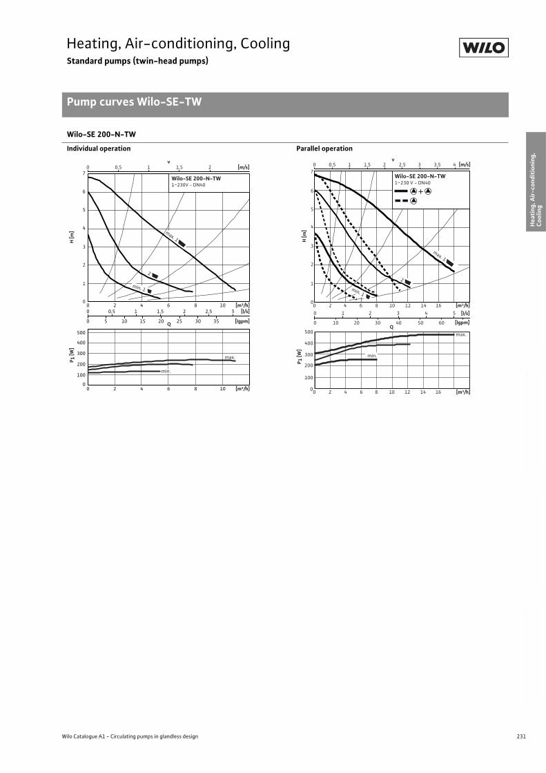
231
Heating, Air-conditioning, CoolingStandard pumps (twin-head pumps)
Pump curves Wilo-SE-TW
Wilo Catalogue A1 - Circulating pumps in glandless design
Hea
tin
g, A
ir-c
on
dit
ion
ing
, C
oo
ling
Po
tab
le w
ater
cir
cula
tio
nSo
lar
ther
mal
Serv
ice/
Acc
esso
ries
, Sys
tem
sSw
itch
gea
rs a
nd
Co
ntr
ol
Dev
ices
P
um
p M
anag
emen
t S y
stem
s
Wilo-SE 200-N-TW
Individual operation Parallel operation
H [m
]P 1
[W]
[l/s]
[Igpm]
[m/s]v
Q
21,510 0,5
4
5
6
7
0
100
200
300
400
500
3
2
1
0
0 5 10 15 20 25 30 35
[m³/h]0 2 4 6 8 10
0 0,5 1 1,5 2 2,5 3
[m³/h]0 2 4 6 8 10
Wilo-SE 200-N-TW1~230V - DN40
max. 1
min. 1
2
min.
max.
H [m
]P 1
[W]
00 2 4 6 8 10 12 14 16 [m³/h]
200
100
300
400
500
[Igpm]
v
min. 1
2
max.
[m/s]43,53
3
4
2,52
2
6
7
5
1,51
1
0
00 2 4 6 8 10
Q
12 14 16
543210
2010 4030 50 600
[m³/h][l/s]
0,5
+
max. 1
Wilo-SE 200-N-TW1~230 V - DN40
min.
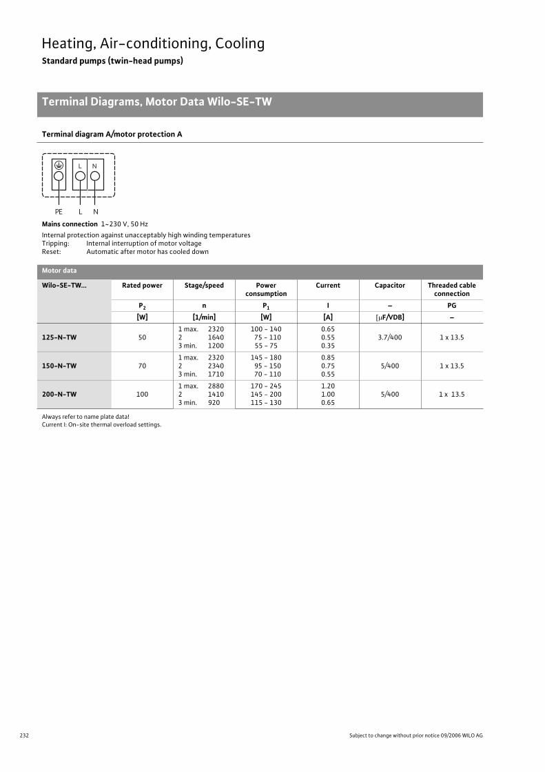
232 Subject to change without prior notice 09/2006 WILO AG
Heating, Air-conditioning, CoolingStandard pumps (twin-head pumps)
Terminal Diagrams, Motor Data Wilo-SE-TW
Terminal diagram A/motor protection A
Mains connection 1~230 V, 50 Hz
Internal protection against unacceptably high winding temperaturesTripping: Internal interruption of motor voltageReset: Automatic after motor has cooled down
Motor data
Wilo-SE-TW... Rated power Stage/speed Power consumption
Current Capacitor Threaded cable connection
P2 n P1 I – PG
[W] [1/min] [W] [A] F/VDB] –
125-N-TW 501 max. 2320 2 16403 min. 1200
100 - 140 75 - 110
55 - 75
0.650.550.35
3.7/400 1 x 13.5
150-N-TW 701 max. 2320 2 23403 min. 1710
145 - 180 95 - 150 70 - 110
0.850.750.55
5/400 1 x 13.5
200-N-TW 1001 max. 2880 2 14103 min. 920
170 - 245145 - 200115 - 130
1.201.000.65
5/400 1 x 13.5
Always refer to name plate data!Current I: On-site thermal overload settings.
L NPE
NL
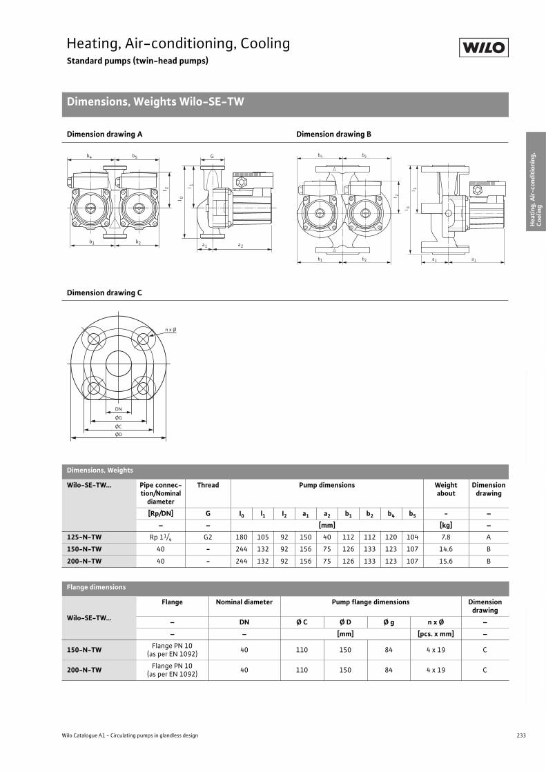
233
Heating, Air-conditioning, CoolingStandard pumps (twin-head pumps)
Dimensions, Weights Wilo-SE-TW
Wilo Catalogue A1 - Circulating pumps in glandless design
Hea
tin
g, A
ir-c
on
dit
ion
ing
, C
oo
ling
Po
tab
le w
ater
cir
cula
tio
nSo
lar
ther
mal
Serv
ice/
Acc
esso
ries
, Sys
tem
sSw
itch
gea
rs a
nd
Co
ntr
ol
Dev
ices
P
um
p M
anag
emen
t S y
stem
s
Dimension drawing A Dimension drawing B
Dimension drawing C
Dimensions, Weights
Wilo-SE-TW... Pipe connec-tion/Nominal
diameter
Thread Pump dimensions Weightabout
Dimensiondrawing
[Rp/DN] G I0 l1 I2 a1 a2 b1 b2 b4 b5 - –
– – [mm] [kg] –
125-N-TW Rp 11/4 G2 180 105 92 150 40 112 112 120 104 7.8 A
150-N-TW 40 - 244 132 92 156 75 126 133 123 107 14.6 B
200-N-TW 40 - 244 132 92 156 75 126 133 123 107 15.6 B
Flange dimensions
Wilo-SE-TW...
Flange Nominal diameter Pump flange dimensions Dimension drawing
– DN Ø C Ø D Ø g n x Ø –
– – [mm] [pcs. x mm] –
150-N-TWFlange PN 10
(as per EN 1092)40 110 150 84 4 x 19 C
200-N-TWFlange PN 10
(as per EN 1092)40 110 150 84 4 x 19 C
b4
l 2
l 0
l 1
b5 G
b1 b2 a1 a2
l 2
l 0
l 1
b4 b5
b1 b2 a1a2
DN
ØG
ØC
ØD
n x Ø
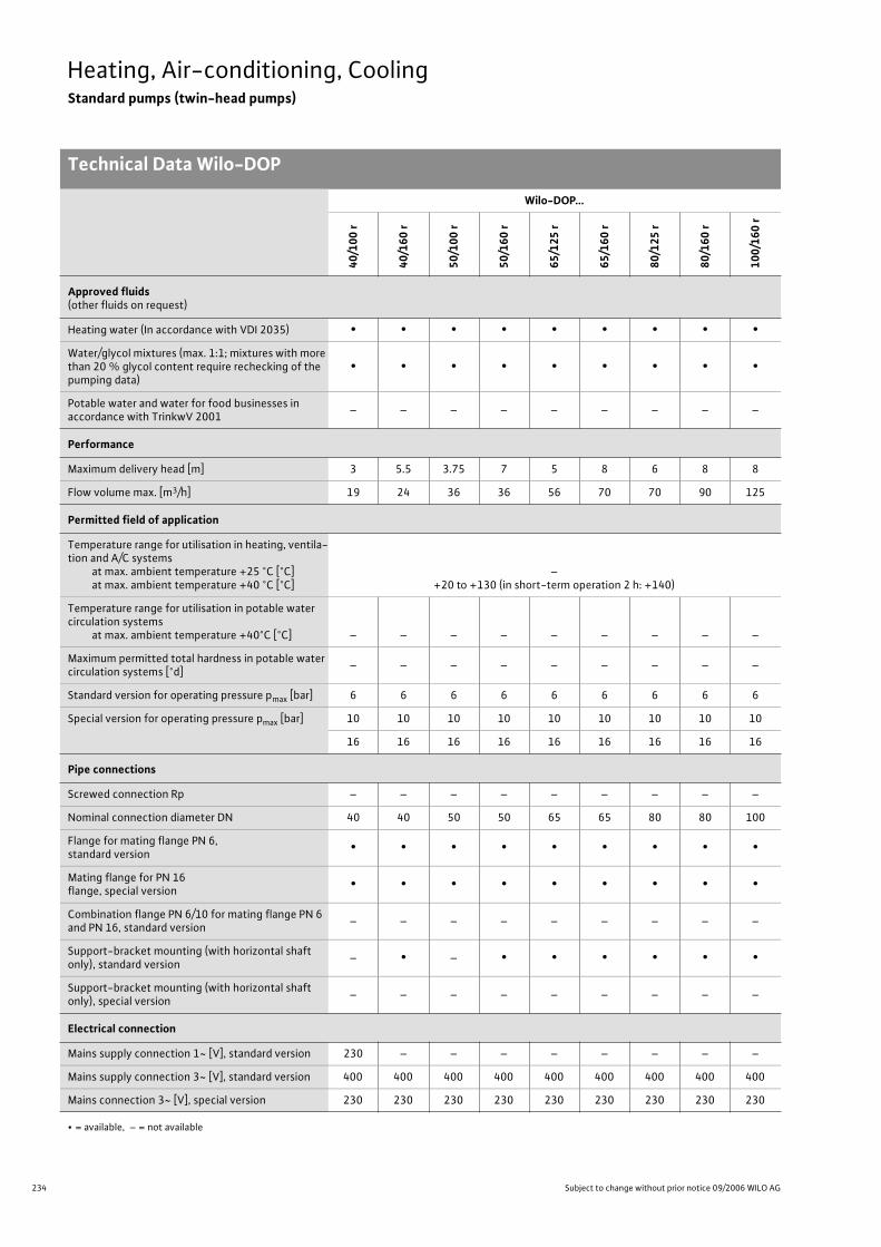
234 Subject to change without prior notice 09/2006 WILO AG
Heating, Air-conditioning, CoolingStandard pumps (twin-head pumps)
Technical Data Wilo-DOP
Wilo-DOP...
40
/10
0 r
40
/16
0 r
50
/10
0 r
50
/16
0 r
65
/12
5 r
65
/16
0 r
80
/12
5 r
80
/16
0 r
10
0/1
60
r
Approved fluids(other fluids on request)
Heating water (In accordance with VDI 2035) • • • • • • • • •
Water/glycol mixtures (max. 1:1; mixtures with more than 20 % glycol content require rechecking of the pumping data)
• • • • • • • • •
Potable water and water for food businesses in accordance with TrinkwV 2001
– – – – – – – – –
Performance
Maximum delivery head [m] 3 5.5 3.75 7 5 8 6 8 8
Flow volume max. [m3/h] 19 24 36 36 56 70 70 90 125
Permitted field of application
Temperature range for utilisation in heating, ventila-tion and A/C systems
at max. ambient temperature +25 °C [°C]at max. ambient temperature +40 °C [°C]
–+20 to +130 (in short-term operation 2 h: +140)
Temperature range for utilisation in potable water circulation systems
at max. ambient temperature +40°C [°C] – – – – – – – – –
Maximum permitted total hardness in potable water circulation systems [°d]
– – – – – – – – –
Standard version for operating pressure pmax [bar] 6 6 6 6 6 6 6 6 6
Special version for operating pressure pmax [bar] 10 10 10 10 10 10 10 10 10
16 16 16 16 16 16 16 16 16
Pipe connections
Screwed connection Rp – – – – – – – – –
Nominal connection diameter DN 40 40 50 50 65 65 80 80 100
Flange for mating flange PN 6, standard version
• • • • • • • • •
Mating flange for PN 16 flange, special version
• • • • • • • • •
Combination flange PN 6/10 for mating flange PN 6 and PN 16, standard version
– – – – – – – – –
Support-bracket mounting (with horizontal shaft only), standard version
– • – • • • • • •
Support-bracket mounting (with horizontal shaft only), special version
– – – – – – – – –
Electrical connection
Mains supply connection 1~ [V], standard version 230 – – – – – – – –
Mains supply connection 3~ [V], standard version 400 400 400 400 400 400 400 400 400
Mains connection 3~ [V], special version 230 230 230 230 230 230 230 230 230
• = available, – = not available
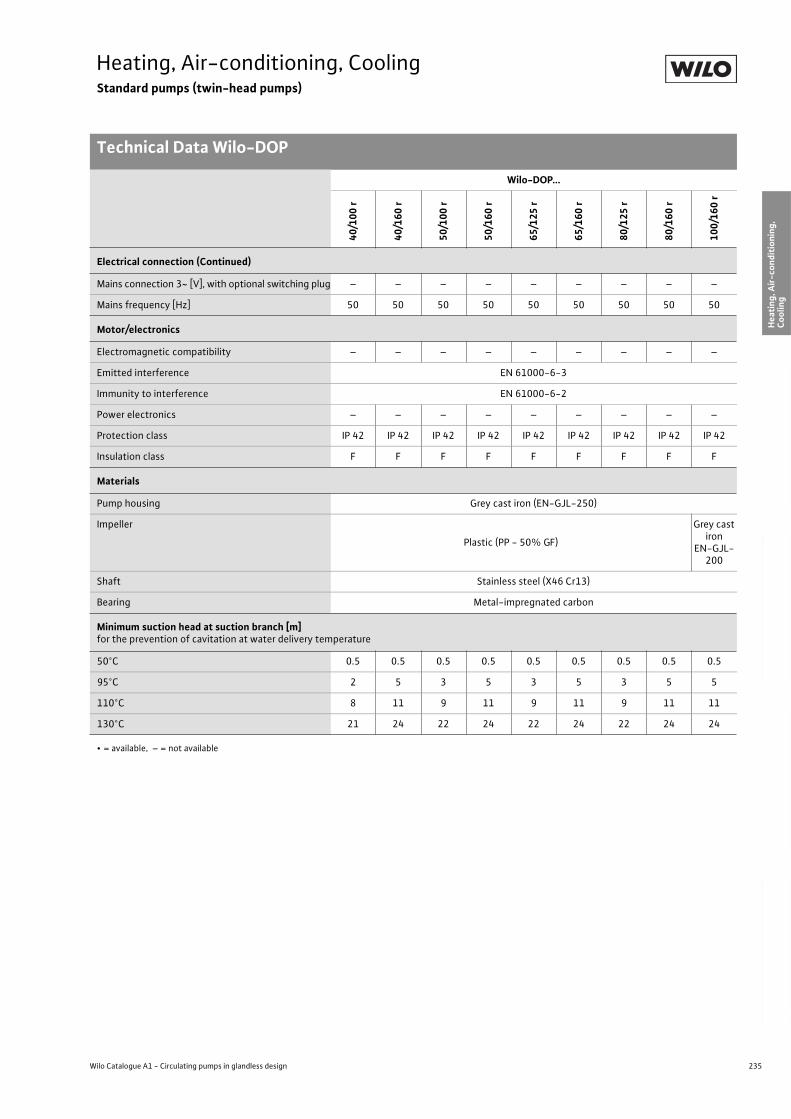
235
Heating, Air-conditioning, CoolingStandard pumps (twin-head pumps)
Technical Data Wilo-DOP
Wilo Catalogue A1 - Circulating pumps in glandless design
Hea
tin
g, A
ir-c
on
dit
ion
ing
, C
oo
ling
Po
tab
le w
ater
cir
cula
tio
nSo
lar
ther
mal
Serv
ice/
Acc
esso
ries
, Sys
tem
sSw
itch
gea
rs a
nd
Co
ntr
ol
Dev
ices
P
um
p M
anag
emen
t S y
stem
s
Electrical connection (Continued)
Mains connection 3~ [V], with optional switching plug – – – – – – – – –
Mains frequency [Hz] 50 50 50 50 50 50 50 50 50
Motor/electronics
Electromagnetic compatibility – – – – – – – – –
Emitted interference EN 61000-6-3
Immunity to interference EN 61000-6-2
Power electronics – – – – – – – – –
Protection class IP 42 IP 42 IP 42 IP 42 IP 42 IP 42 IP 42 IP 42 IP 42
Insulation class F F F F F F F F F
Materials
Pump housing Grey cast iron (EN-GJL-250)
Impeller
Plastic (PP - 50% GF)
Grey cast iron
EN-GJL-200
Shaft Stainless steel (X46 Cr13)
Bearing Metal-impregnated carbon
Minimum suction head at suction branch [m]for the prevention of cavitation at water delivery temperature
50°C 0.5 0.5 0.5 0.5 0.5 0.5 0.5 0.5 0.5
95°C 2 5 3 5 3 5 3 5 5
110°C 8 11 9 11 9 11 9 11 11
130°C 21 24 22 24 22 24 22 24 24
Wilo-DOP...
40
/10
0 r
40
/16
0 r
50
/10
0 r
50
/16
0 r
65
/12
5 r
65
/16
0 r
80
/12
5 r
80
/16
0 r
10
0/1
60
r
• = available, – = not available
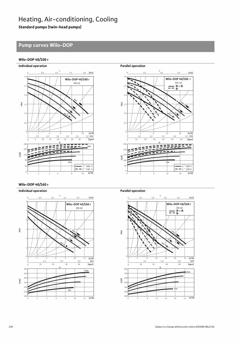
236 Subject to change without prior notice 09/2006 WILO AG
Heating, Air-conditioning, CoolingStandard pumps (twin-head pumps)
Pump curves Wilo-DOP
Wilo-DOP 40/100 r
Individual operation Parallel operation
Wilo-DOP 40/160 r
Individual operation Parallel operation
max.
Q
00
00
Wilo-DOP 40/100 r DN 40
2
1,0
1,5
2,0
160
40
64
120
3 ~ 400 V1 ~ 230 V
2 64
0,5
8
2,5
3,0
80
200
min.
8
10
(3 )min.(4 )
(2 )
max. )
10
0,50 [m/s]v
1,0 1,5 2,0
0
0
[l/s]
[lgpm]
0,5 1,0
105 15
1,5
20
2,0 2,5 3,0
25 30 35
[m3/h]
P 1[W]
H[m
]
[m3/h]
Q
1,00
00
0
0
[l/s]
[lgpm]
0
80
1,0
[m/s]
1,0
1,5
2,0
v2,0 3,0
240
124
320
4
0,5
8
2,5
3,0
2,0 3,0 4,0 5,0
400
8
16
(3 )min.(4
)
(2 )
max.(1
)
12
Wilo-DOP 40/100 rDN 40
16
160
max.
3 ~ 400 V 1 ~ 230 V
0
min.
605040302010
+
[m3/h]
P 1[W]
H[m
]
[m3/h]
max.
Q
0,50
00
0
0
[l/s]
[lgpm]
0
Wilo-DOP 40/160 rDN 40
2
[m/s]
2
3
4
v 1,0 2,0
350
200
64
300
2 64
1
8
5
6
1,0 2,0
10 20 30
250
400
min.
8
10
(3 )
(2 )
10
1,5
12
max.(1 )
min. (4 )
3,0
40
150
10012
[m3/h]
P 1[W]
H[m
]
[m3/h]
max.
Q
1,00
00
0
0
[l/s]
[lgpm]
0
4
[m/s]
2
3
4
v 2,0 4,0
700
400
128
600
4 128
1
16
5
6
2,0 4,0
20 40 60
500
800
min.
16
20
(3 ) (2 )
20
3,0
24
max.(1 )
min. (4 )
6,0
80
300
20024
Wilo-DOP 40/160 r DN 40
[m3/h]
P 1[W]
H[m
]
+
[m3/h]
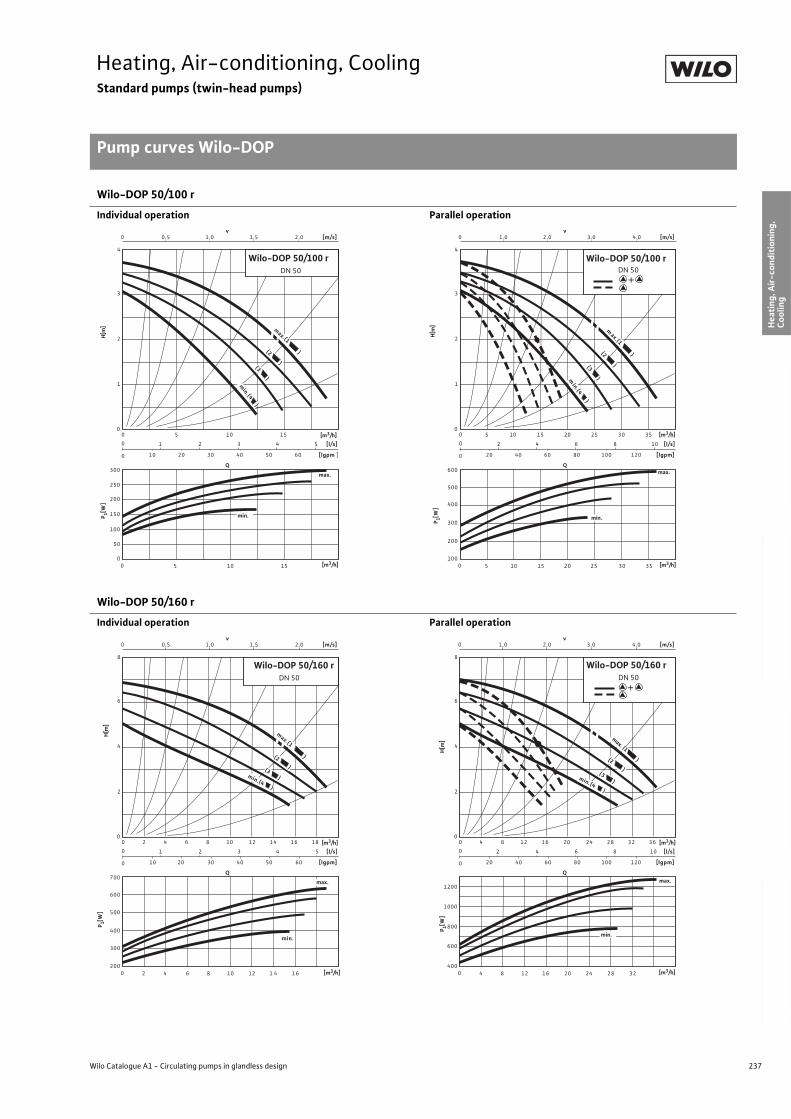
237
Heating, Air-conditioning, CoolingStandard pumps (twin-head pumps)
Pump curves Wilo-DOP
Wilo Catalogue A1 - Circulating pumps in glandless design
Hea
tin
g, A
ir-c
on
dit
ion
ing
, C
oo
ling
Po
tab
le w
ater
cir
cula
tio
nSo
lar
ther
mal
Serv
ice/
Acc
esso
ries
, Sys
tem
sSw
itch
gea
rs a
nd
Co
ntr
ol
Dev
ices
P
um
p M
anag
emen
t S y
stem
s
Wilo-DOP 50/100 r
Individual operation Parallel operation
Wilo-DOP 50/160 r
Individual operation Parallel operation
Q
0,50
00
0
0
[l/s]
[lgpm ]
0
Wilo-DOP 50/100 r DN 50
[m/s]
2
3
v1,0 2,0
250
100
5
200
5
1
4
1 2
150
300
10
10
1,5
15
3
50
015
min.(4 )
(3)
(2
)
max.(1
)
4 5
min.
max.
10 20 30 40 50 60
[m3/h]
P 1[W]
H[m
]
[m3/h] [m3/h]
P 1[W]
H[m
]
+
max.Q
1,00
00
0
0
[l/s]
[lgpm]
0
[m/s]
2
3
v2,0 4,0
200
5
500
5
1
4
2 4
20 40
600
10
10
3,0
15
6
120
300
10015
min.(4 )
(3 )(2 )
max.(1 )
8 10
60 80 100
min.
20 25 30 35
Wilo-DOP 50/100 r DN 50
400
20 25 30 35
+
[m3/h]
Q
0,50
00
0
0
[l/s]
[lgpm]
0
Wilo-DOP 50/160 r DN 50
[m/s]
4
6
v1,0 2,0
400
2
600
4
2
8
1 2
10 20
500
700
10
10
1,5
12
3
300
20012
(3 )
(2)
max.(1
)
4 5
30 40
min.
4 6 8 14 16 18
min.(4 )
max.
2 6 8 1 4 16
6050
[m3/h]
P 1[W]
H[m
]
[m3/h]
Q
1,00
00
0
0
[l/s]
[lgpm]
0
[m/s]
4
6
v2,0 4,0
800
4
1200
8
2
8
2 4
1000
20
20
3,0
24
6
600
40024
(2)
max. (1
)
8 10
8 12 16 28 32 36
min.(4 )
max.
4 12 16 28 32
(3 )
Wilo-DOP 50/160 r DN 50
min.
20 40 60 80 100 120
[m3/h]
P 1[W]
H[m
]
+
[m3/h]
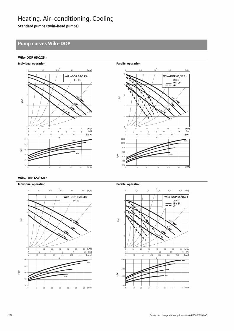
238 Subject to change without prior notice 09/2006 WILO AG
Heating, Air-conditioning, CoolingStandard pumps (twin-head pumps)
Pump curves Wilo-DOP
Wilo-DOP 65/125 r
Individual operation Parallel operation
Wilo-DOP 65/160 r
Individual operation Parallel operation
Q
0,50
00
0
0
[l/s]
[lgpm]
0
Wilo-DOP 65/125 r DN 65
[m/s]
3
4
v1,0
300
5
500
5
2
5
1 2
20
400
600
15
10
1,5
3
200
10015
4 5
40
min.
10 20 25
min.(4)
max.
20 25
1
(3)
(2
)
max.(1
)
6 7
60 80
[m3/h]
P 1[W]
H[m
]
[m3/h]
Q
1,00
00
0
0
[l/s]
[lgpm]
0
[m/s]
3
4
v2,0
600
10
900
10
2
5
2 4
40
750
1200
30
20
3,0
6
450
30030
8 10
80
min.
20 40 50
min.(4)
max.
40 50
1
(3 )
(2 )
min .(1
)
12 14
120 160
1050
Wilo-DOP 65/125 r DN 65
[m3/h]
P 1[W]
H[m
]
+
[m3/h]
Q
0,50
00
0
0
[l/s]
[lgpm]
0
[m/s]
6
v 1,0
400
5
800
5
2
8
2
20
600
1000
15
10
1,5
4
20015
6
40
min.
10 20 25
max.
20 25
(3 )
10
60 100
Wilo-DOP 65/160 r DN 65
2,0 2,5
30 35
min.(4 )
(2 )
max.(1 )
8
80 120
30 35
4
[m3/h]
P 1[W]
H[m
]
[m3/h]
Q
1,00
00
0
0
[l/s]
[lgpm]
0
[m/s]
6
v 2,0
10
10
4
40
2000
30
20
3,0
8
50030
12
80
20 40 50
max.
40 50
(3 )
20
120 200
4,0 5,0
60 70
min.(4 )
(2 )
16
160 240
60 70
Wilo-DOP 65/160 r DN 65
max.(1 )
1500
1000 min.
2
8
4
[m3/h]
P 1[W]
H[m
]
+
[m3/h]
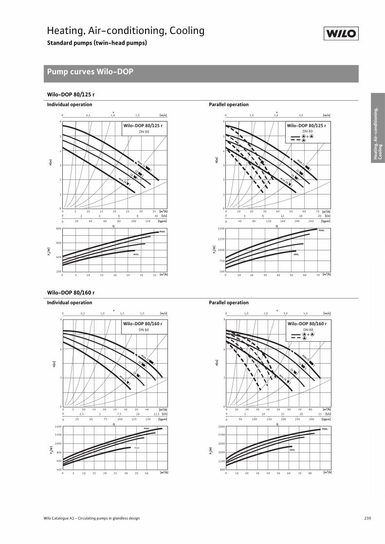
239
Heating, Air-conditioning, CoolingStandard pumps (twin-head pumps)
Pump curves Wilo-DOP
Wilo Catalogue A1 - Circulating pumps in glandless design
Hea
tin
g, A
ir-c
on
dit
ion
ing
, C
oo
ling
Po
tab
le w
ater
cir
cula
tio
nSo
lar
ther
mal
Serv
ice/
Acc
esso
ries
, Sys
tem
sSw
itch
gea
rs a
nd
Co
ntr
ol
Dev
ices
P
um
p M
anag
emen
t S y
stem
s
Wilo-DOP 80/125 r
Individual operation Parallel operation
Wilo-DOP 80/160 r
Individual operation Parallel operation
Q
0,50
00
0
0
[l/s]
[lgpm]
0
[m/s]
4
v 1,0
5
600
5
2
6
2
20
400
800
15
10
1,5
4
20015
6
40
min.
10 20 25
max.
20 25
10
60 100
Wilo-DOP 80/125 rDN 80
30 35
(2 )
8
80 120
30 35
5
3
1
max.(1 )(3 )min.(4 )
[m3/h]
P 1[W]
H[m
]
[m3/h]
Q
1,00
00
0
0
[l/s]
[lgpm]
0
[m/s]
4
v2,0
10
10
2
6
4
40
750
1500
30
20
3,0
8
50030
12
80
min.
20 40 50
max.
40 50
20
120 200
60 70
(2 )
16
160 240
60 70
5
3
1
max.(1
)
(3 )m in .(4)
Wilo-DOP 80/125 r DN 80
1250
1000
[m3/h]
P 1[W]
H[m
]
+
[m3/h]
Q
0,50
00
0
0
[l/s]
[lgpm]
0
[m/s]
6
v1,0
5
800
5
3
9
2,5
25
600
1400
15
10
2,0
5
40015
7,5
50
10 20 25
20 25
12,5
75 125
Wilo-DOP 80/160 r DN 80
30 35
10
100 150
30 35
max.(1 )
(3 )
1,5
40
min.(4)
(2 )
1200
1000min.
max.
40 [m3/h]
[m3/h]
P 1[W]
H[m
]
Q
1,00
00
0
0
[l/s]
[lgpm]
0
[m/s]
6
v2,0
10
10
3
9
5
50
2800
30
20
4,0
10
80030
15
100
min.
20 40 50
max.
40 50
25
150 250
60 70
20
200 300
60 70
max.(1
)(3 )
3,0
80
min.(4)
(2 )
2400
2000
Wilo-DOP 80/160 r DN 80
1600
1200
80
[m3/h]
P 1[W]
H[m
]
+
[m3/h]
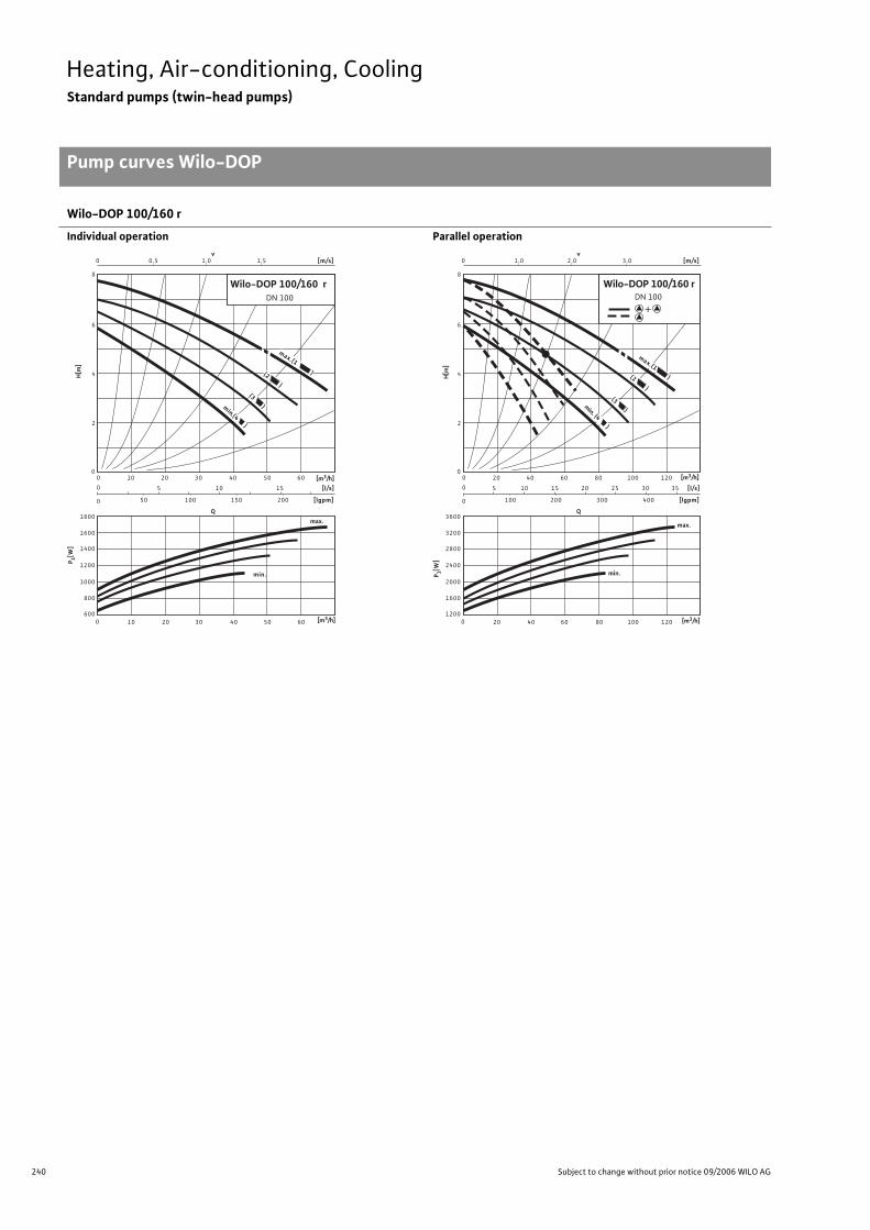
240 Subject to change without prior notice 09/2006 WILO AG
Heating, Air-conditioning, CoolingStandard pumps (twin-head pumps)
Pump curves Wilo-DOP
Wilo-DOP 100/160 r
Individual operation Parallel operation
Q
0,50
00
0
0
[l/s]
[lgpm]
0
[m/s]
6
v 1,0
1200
2
8
800
1800
20
10
5
600
50
10 30
20
Wilo-DOP 100/160 rDN 100
40 50
10
100 150
30
1,5
60
1600
1400
min.
max.
40
4
15
200
50 60
min.(4 )
(3 )
(2 )
max.(1 )
1000
[m3/h]
P 1[W]
H[m
]
[m3/h]
Q
1,00
00
0
0
[l/s]
[lgpm]
0
[m/s]
6
v2,0
2400
2
8
5
1600
3600
40
20
10
1200
15
100
20 60
40
25
80 100
20
200 300
60
3,0
120
3200
2800
min.
max.
80
4
30 35
400
100 120
min. (4)
(3)
(2 )
max.(1 )
2000
DN 100Wilo-DOP 100/160 r
[m3/h]
P 1[W]
H[m
]
+
[m3/h]
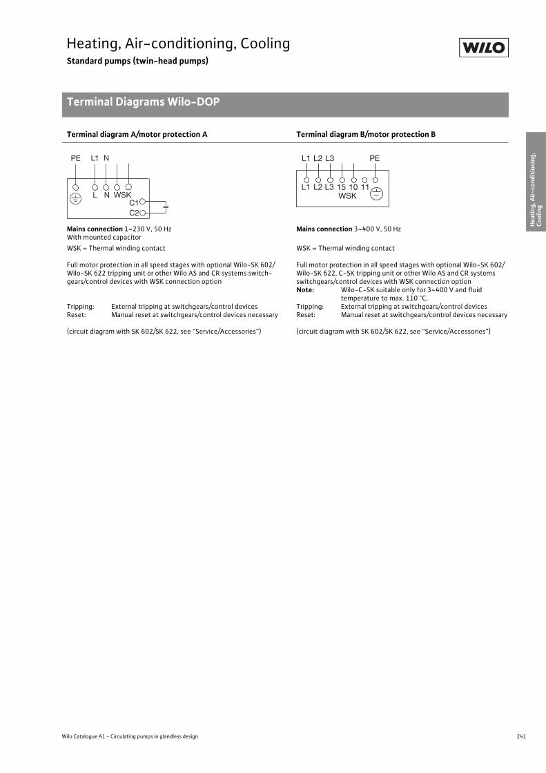
241
Heating, Air-conditioning, CoolingStandard pumps (twin-head pumps)
Terminal Diagrams Wilo-DOP
Wilo Catalogue A1 - Circulating pumps in glandless design
Hea
tin
g, A
ir-c
on
dit
ion
ing
, C
oo
ling
Po
tab
le w
ater
cir
cula
tio
nSo
lar
ther
mal
Serv
ice/
Acc
esso
ries
, Sys
tem
sSw
itch
gea
rs a
nd
Co
ntr
ol
Dev
ices
P
um
p M
anag
emen
t S y
stem
s
Terminal diagram A/motor protection A Terminal diagram B/motor protection B
Mains connection 1~230 V, 50 HzWith mounted capacitor
Mains connection 3~400 V, 50 Hz
WSK = Thermal winding contact
Full motor protection in all speed stages with optional Wilo-SK 602/Wilo-SK 622 tripping unit or other Wilo AS and CR systems switch-gears/control devices with WSK connection option
Tripping: External tripping at switchgears/control devicesReset: Manual reset at switchgears/control devices necessary
(circuit diagram with SK 602/SK 622, see “Service/Accessories”)
WSK = Thermal winding contact
Full motor protection in all speed stages with optional Wilo-SK 602/Wilo-SK 622, C-SK tripping unit or other Wilo AS and CR systems switchgears/control devices with WSK connection optionNote: Wilo-C-SK suitable only for 3~400 V and fluid
temperature to max. 110 °C.Tripping: External tripping at switchgears/control devicesReset: Manual reset at switchgears/control devices necessary
(circuit diagram with SK 602/SK 622, see “Service/Accessories”)
L
PE L1 N
N WSKC1C2
L1WSK
L2 L3 15 10 11
PEL1 L2 L3
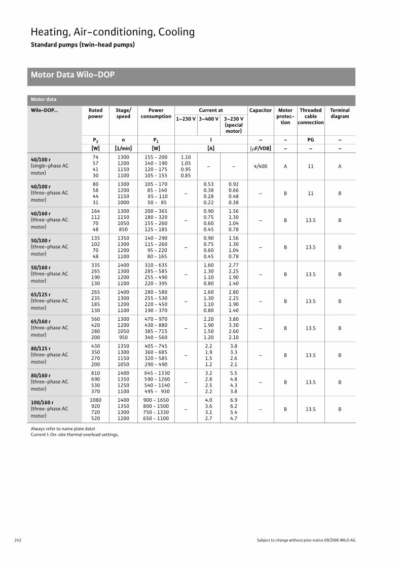
242 Subject to change without prior notice 09/2006 WILO AG
Heating, Air-conditioning, CoolingStandard pumps (twin-head pumps)
Motor Data Wilo-DOP
Motor data
Wilo-DOP... Rated power
Stage/speed
Power consumption
Current at Capacitor Motor protec-
tion
Threaded cable
connection
Terminal diagram1~230 V 3~400 V 3~230 V
(specialmotor)
P2 n P1 I – – PG –
[W] [1/min] [W] [A] F/VDB] – – –
40/100 r(single-phase AC
motor)
74574130
1300120011501100
155 - 200140 - 190120 - 175105 - 155
1.101.050.950.85
– – 4/400 A 11 A
40/100 r(three-phase AC
motor)
80584431
1300120011501000
105 - 170 85 - 140 65 - 110 50 - 85
–
0.530.380.280.22
0.920.660.480.38
– B 11 B
40/160 r(three-phase AC
motor)
1641127048
130011501050850
200 - 365180 - 320155 - 260125 - 185
–
0.900.750.600.45
1.561.301.040.78
– B 13.5 B
50/100 r(three-phase AC
motor)
1351027048
1350130012001100
140 - 290115 - 260 95 - 220 80 - 165
–
0.900.750.600.45
1.561.301.040.78
– B 13.5 B
50/160 r(three-phase AC
motor)
335265190130
1400130012001100
310 - 635285 - 585255 - 490220 - 395
–
1.601.301.100.80
2.772.251.901.40
– B 13.5 B
65/125 r(three-phase AC
motor)
265235185130
1400130012001100
280 - 580255 - 530220 - 450190 - 370
–
1.601.301.100.80
2.802.251.901.40
– B 13.5 B
65/160 r(three-phase AC
motor)
560420280200
130012001050950
470 - 970430 - 880385 - 715340 - 560
–
2.201.901.501.20
3.803.302.602.10
– B 13.5 B
80/125 r(three-phase AC
motor)
430350270200
1350130011501050
405 - 745360 - 685320 - 585290 - 490
–
2.21.91.51.2
3.83.32.62.1
– B 13.5 B
80/160 r(three-phase AC
motor)
810690530370
1400135012501100
645 - 1330 590 - 1260 540 - 1140 495 - 930
–
3.22.82.52.2
5.54.84.33.8
– B 13.5 B
100/160 r(three-phase AC
motor)
1080920720520
1400135013001200
900 - 1650800 - 1500750 - 1330650 - 1100
–
4.03.63.12.7
6.96.25.44.7
– B 13.5 B
Always refer to name plate data!Current I: On-site thermal overload settings.
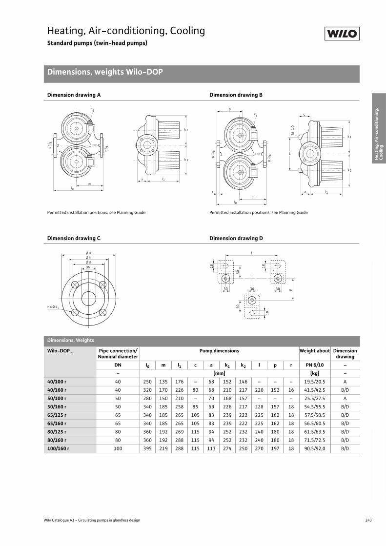
243
Heating, Air-conditioning, CoolingStandard pumps (twin-head pumps)
Dimensions, weights Wilo-DOP
Wilo Catalogue A1 - Circulating pumps in glandless design
Hea
tin
g, A
ir-c
on
dit
ion
ing
, C
oo
ling
Po
tab
le w
ater
cir
cula
tio
nSo
lar
ther
mal
Serv
ice/
Acc
esso
ries
, Sys
tem
sSw
itch
gea
rs a
nd
Co
ntr
ol
Dev
ices
P
um
p M
anag
emen
t S y
stem
s
Dimension drawing A Dimension drawing B
Permitted installation positions, see Planning Guide Permitted installation positions, see Planning Guide
Dimension drawing C Dimension drawing D
Dimensions, Weights
Wilo-DOP... Pipe connection/Nominal diameter
Pump dimensions Weight about Dimension drawing
DN I0 m l1 c a k1 k2 l p r PN 6/10 –
– [mm] [kg] –
40/100 r 40 250 135 176 – 68 152 146 – – – 19.5/20.5 A
40/160 r 40 320 170 226 80 68 210 217 220 152 16 41.5/42.5 B/D
50/100 r 50 280 150 210 – 70 168 157 – – – 25.5/27.5 A
50/160 r 50 340 185 258 85 69 226 217 228 157 18 54.5/55.5 B/D
65/125 r 65 340 185 265 105 83 239 222 225 162 18 57.5/58.5 B/D
65/160 r 65 340 185 265 105 83 239 222 225 162 18 56.5/60.5 B/D
80/125 r 80 360 192 269 115 94 252 232 240 180 18 61.5/63.5 B/D
80/160 r 80 360 192 288 115 94 252 232 240 180 18 71.5/72.5 B/D
100/160 r 100 395 219 288 115 113 274 250 270 197 18 90.5/92.0 B/D
k 1
k 2
l1
l0
Pg
am
R 1 /
8
R 1 /
8
k 1
k 2
l1
l0
cPgP
am
r
M 1
0
R 1
/ 8
R 1
/ 8
L
n x Ø d
Ø D Ø k
DN
Ø d
L
l
50
p
50
18
18 18
303030
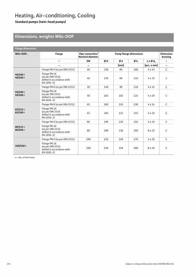
244 Subject to change without prior notice 09/2006 WILO AG
Heating, Air-conditioning, CoolingStandard pumps (twin-head pumps)
Dimensions, weights Wilo-DOP
Flange dimensions
Wilo-DOP... Flange Pipe connection/Nominal diameter
Pump flange dimensions Dimension drawing
– DN Ø D Ø d Ø k n x Ø dL –
– – [mm] [pcs. x mm] –
40/100 r 40/160 r
Flange PN 6 (as per DIN 2531) 40 130 80 100 4 x 14 C
Flange PN 16(as per DIN 2533,drilled in accordance with EN 1092-2)
40 150 88 110 4 x 19 C
50/100 r50/160 r
Flange PN 6 (as per DIN 2531) 50 140 90 110 4 x 14 C
Flange PN 16(as per DIN 2533drilled in accordance with EN 1092-2)
50 165 102 125 4 x 19 C
65/125 r 65/160 r
Flange PN 6 (as per DIN 2531) 65 160 110 130 4 x 14 C
Flange PN 16(as per DIN 2533drilled in accordance with EN 1092-2)
65 185 122 145 4 x 19 C
80/125 r80/160 r
Flange PN 6 (as per DIN 2531) 80 190 128 150 4 x 19 C
Flange PN 16(as per DIN 2533drilled in accordance with EN 1092-2)
80 200 138 160 8 x 19 C
100/160 r
Flange PN 6 (as per DIN 2531) 100 210 148 170 4 x 19 C
Flange PN 16(as per DIN 2533,drilled in accordance with EN 1092-2)
100 220 158 180 8 x 19 C
n = No. of bolt holes
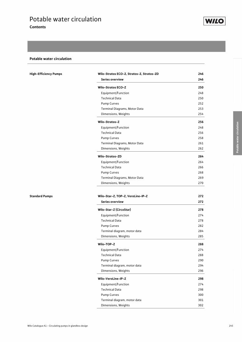
245
Potable water circulationContents
Wilo Catalogue A1 - Circulating pumps in glandless design
Hea
tin
g, A
ir-c
on
dit
ion
ing
, C
oo
ling
Po
tab
le w
ater
cir
cula
tio
nSo
lar
ther
mal
Serv
ice/
Acc
esso
ries
, Sys
tem
sSw
itch
gea
rs a
nd
Co
ntr
ol
Dev
ices
P
um
p M
anag
emen
t S y
stem
s
Potable water circulation
High-Efficiency Pumps Wilo-Stratos ECO-Z, Stratos-Z, Stratos-ZD 246
Series overview 246
Wilo-Stratos ECO-Z 250
Equipment/Function 248
Technical Data 250
Pump Curves 252
Terminal Diagrams, Motor Data 253
Dimensions, Weights 254
Wilo-Stratos-Z 256
Equipment/Function 248
Technical Data 256
Pump Curves 258
Terminal Diagrams, Motor Data 261
Dimensions, Weights 262
Wilo-Stratos-ZD 264
Equipment/Function 264
Technical Data 266
Pump Curves 268
Terminal Diagrams, Motor Data 269
Dimensions, Weights 270
Standard Pumps Wilo-Star-Z, TOP-Z, VeroLine-IP-Z 272
Series overview 272
Wilo-Star-Z (CircoStar) 278
Equipment/Function 274
Technical Data 278
Pump Curves 282
Terminal diagram, motor data 284
Dimensions, Weights 285
Wilo-TOP-Z 288
Equipment/Function 274
Technical Data 288
Pump Curves 290
Terminal diagram, motor data 294
Dimensions, Weights 296
Wilo-VeroLine-IP-Z 298
Equipment/Function 274
Technical Data 298
Pump Curves 300
Terminal diagram, motor data 301
Dimensions, Weights 302
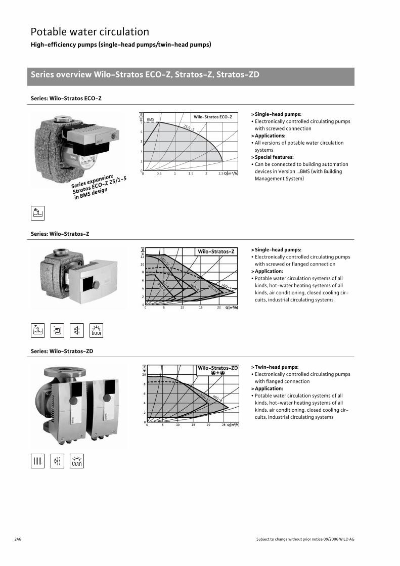
246 Subject to change without prior notice 09/2006 WILO AG
Potable water circulationHigh-efficiency pumps (single-head pumps/twin-head pumps)
Series overview Wilo-Stratos ECO-Z, Stratos-Z, Stratos-ZD
Series: Wilo-Stratos ECO-Z
> Single-head pumps:• Electronically controlled circulating pumps
with screwed connection
> Applications: • All versions of potable water circulation
systems
> Special features: • Can be connected to building automation
devices in Version …BMS (with Building
Management System)
Series: Wilo-Stratos-Z
> Single-head pumps: • Electronically controlled circulating pumps
with screwed or flanged connection
> Application:• Potable water circulation systems of all
kinds, hot-water heating systems of all
kinds, air conditioning, closed cooling cir-
cuits, industrial circulating systems
Series: Wilo-Stratos-ZD
> Twin-head pumps:• Electronically controlled circulating pumps
with flanged connection
> Application:• Potable water circulation systems of all
kinds, hot-water heating systems of all
kinds, air conditioning, closed cooling cir-
cuits, industrial circulating systems
Series exp
ansion:
Stratos EC
O-Z 25/1-5
in BMS des
ign
H [m
]
5
4
3
2
1
0 Q[m³/h]1,5 1 2,5 2 0 0,5
25/1-5
Wilo-Stratos ECO-Z BMS
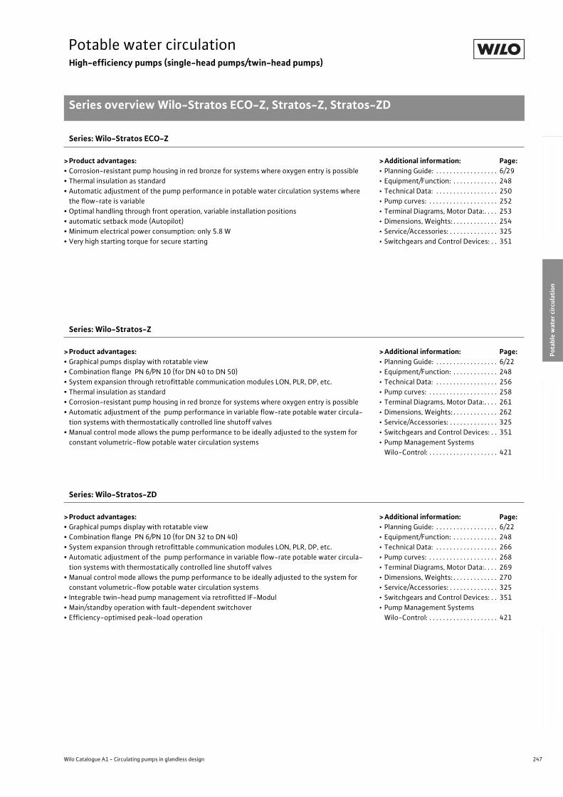
247
Potable water circulationHigh-efficiency pumps (single-head pumps/twin-head pumps)
Series overview Wilo-Stratos ECO-Z, Stratos-Z, Stratos-ZD
Wilo Catalogue A1 - Circulating pumps in glandless design
Hea
tin
g, A
ir-c
on
dit
ion
ing
, C
oo
ling
Po
tab
le w
ater
cir
cula
tio
nSo
lar
ther
mal
Serv
ice/
Acc
esso
ries
, Sys
tem
sSw
itch
gea
rs a
nd
Co
ntr
ol
Dev
ices
P
um
p M
anag
emen
t S y
stem
s
Series: Wilo-Stratos ECO-Z
> Product advantages:• Corrosion-resistant pump housing in red bronze for systems where oxygen entry is possible
• Thermal insulation as standard
• Automatic adjustment of the pump performance in potable water circulation systems where
the flow-rate is variable
• Optimal handling through front operation, variable installation positions
• automatic setback mode (Autopilot)
• Minimum electrical power consumption: only 5.8 W
• Very high starting torque for secure starting
>Additional information: Page:• Planning Guide: . . . . . . . . . . . . . . . . . . 6/29
• Equipment/Function: . . . . . . . . . . . . . 248
• Technical Data: . . . . . . . . . . . . . . . . . . 250
• Pump curves: . . . . . . . . . . . . . . . . . . . . 252
• Terminal Diagrams, Motor Data:. . . . 253
• Dimensions, Weights: . . . . . . . . . . . . . 254
• Service/Accessories: . . . . . . . . . . . . . . 325
• Switchgears and Control Devices: . . 351
Series: Wilo-Stratos-Z
> Product advantages:• Graphical pumps display with rotatable view
• Combination flange PN 6/PN 10 (for DN 40 to DN 50)
• System expansion through retrofittable communication modules LON, PLR, DP, etc.
• Thermal insulation as standard
• Corrosion-resistant pump housing in red bronze for systems where oxygen entry is possible
• Automatic adjustment of the pump performance in variable flow-rate potable water circula-
tion systems with thermostatically controlled line shutoff valves
• Manual control mode allows the pump performance to be ideally adjusted to the system for
constant volumetric-flow potable water circulation systems
>Additional information: Page:• Planning Guide: . . . . . . . . . . . . . . . . . . 6/22
• Equipment/Function: . . . . . . . . . . . . . 248
• Technical Data: . . . . . . . . . . . . . . . . . . 256
• Pump curves: . . . . . . . . . . . . . . . . . . . . 258
• Terminal Diagrams, Motor Data:. . . . 261
• Dimensions, Weights: . . . . . . . . . . . . . 262
• Service/Accessories: . . . . . . . . . . . . . . 325
• Switchgears and Control Devices: . . 351
• Pump Management Systems
Wilo-Control: . . . . . . . . . . . . . . . . . . . . 421
Series: Wilo-Stratos-ZD
> Product advantages:• Graphical pumps display with rotatable view
• Combination flange PN 6/PN 10 (for DN 32 to DN 40)
• System expansion through retrofittable communication modules LON, PLR, DP, etc.
• Automatic adjustment of the pump performance in variable flow-rate potable water circula-
tion systems with thermostatically controlled line shutoff valves
• Manual control mode allows the pump performance to be ideally adjusted to the system for
constant volumetric-flow potable water circulation systems
• Integrable twin-head pump management via retrofitted IF-Modul
• Main/standby operation with fault-dependent switchover
• Efficiency-optimised peak-load operation
>Additional information: Page:• Planning Guide: . . . . . . . . . . . . . . . . . . 6/22
• Equipment/Function: . . . . . . . . . . . . . 248
• Technical Data: . . . . . . . . . . . . . . . . . . 266
• Pump curves: . . . . . . . . . . . . . . . . . . . . 268
• Terminal Diagrams, Motor Data:. . . . 269
• Dimensions, Weights: . . . . . . . . . . . . . 270
• Service/Accessories: . . . . . . . . . . . . . . 325
• Switchgears and Control Devices: . . 351
• Pump Management Systems
Wilo-Control: . . . . . . . . . . . . . . . . . . . . 421
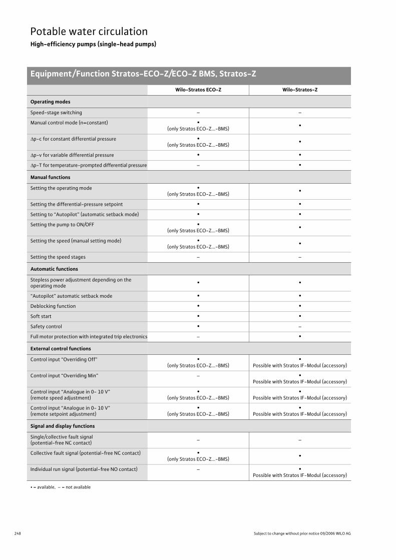
248 Subject to change without prior notice 09/2006 WILO AG
Potable water circulationHigh-efficiency pumps (single-head pumps)
Equipment/Function Stratos-ECO-Z/ECO-Z BMS, Stratos-Z
Wilo-Stratos ECO-Z Wilo-Stratos-Z
Operating modes
Speed-stage switching – –
Manual control mode (n=constant) •(only Stratos ECO-Z...-BMS)
•
p-c for constant differential pressure •(only Stratos ECO-Z...-BMS)
•
p-v for variable differential pressure • •
p-T for temperature-prompted differential pressure – •
Manual functions
Setting the operating mode •(only Stratos ECO-Z...-BMS)
•
Setting the differential-pressure setpoint • •
Setting to “Autopilot” (automatic setback mode) • •
Setting the pump to ON/OFF •(only Stratos ECO-Z...-BMS)
•
Setting the speed (manual setting mode) •(only Stratos ECO-Z...-BMS)
•
Setting the speed stages – –
Automatic functions
Stepless power adjustment depending on the operating mode
• •
“Autopilot” automatic setback mode • •
Deblocking function • •
Soft start • •
Safety control • –
Full motor protection with integrated trip electronics – •
External control functions
Control input “Overriding Off” •(only Stratos ECO-Z...-BMS)
•Possible with Stratos IF-Modul (accessory)
Control input “Overriding Min” – •Possible with Stratos IF-Modul (accessory)
Control input “Analogue in 0- 10 V” (remote speed adjustment)
•(only Stratos ECO-Z...-BMS)
•Possible with Stratos IF-Modul (accessory)
Control input “Analogue in 0- 10 V” (remote setpoint adjustment)
•(only Stratos ECO-Z...-BMS)
•Possible with Stratos IF-Modul (accessory)
Signal and display functions
Single/collective fault signal (potential-free NC contact)
– –
Collective fault signal (potential-free NC contact) •(only Stratos ECO-Z...-BMS)
•
Individual run signal (potential-free NO contact) – •Possible with Stratos IF-Modul (accessory)
• = available, – = not available
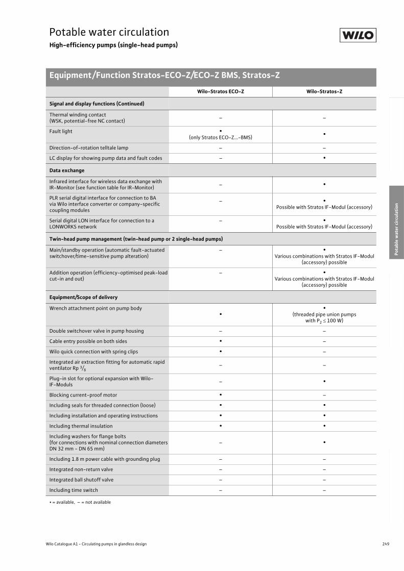
249
Potable water circulationHigh-efficiency pumps (single-head pumps)
Equipment/Function Stratos-ECO-Z/ECO-Z BMS, Stratos-Z
Wilo Catalogue A1 - Circulating pumps in glandless design
Hea
tin
g, A
ir-c
on
dit
ion
ing
, C
oo
ling
Po
tab
le w
ater
cir
cula
tio
nSo
lar
ther
mal
Serv
ice/
Acc
esso
ries
, Sys
tem
sSw
itch
gea
rs a
nd
Co
ntr
ol
Dev
ices
P
um
p M
anag
emen
t S y
stem
s
Signal and display functions (Continued)
Thermal winding contact (WSK, potential-free NC contact)
– –
Fault light •(only Stratos ECO-Z...-BMS)
•
Direction-of-rotation telltale lamp – –
LC display for showing pump data and fault codes – •
Data exchange
Infrared interface for wireless data exchange with IR-Monitor (see function table for IR-Monitor)
– •
PLR serial digital interface for connection to BA via Wilo interface converter or company-specific coupling modules
– •Possible with Stratos IF-Modul (accessory)
Serial digital LON interface for connection to a LONWORKS network
– •Possible with Stratos IF-Modul (accessory)
Twin-head pump management (twin-head pump or 2 single-head pumps)
Main/standby operation (automatic fault-actuated switchover/time-sensitive pump alteration)
– •Various combinations with Stratos IF-Modul
(accessory) possible
Addition operation (efficiency-optimised peak-load cut-in and out)
– •Various combinations with Stratos IF-Modul
(accessory) possible
Equipment/Scope of delivery
Wrench attachment point on pump body•
•(threaded pipe union pumps
with P2 100 W)
Double switchover valve in pump housing – –
Cable entry possible on both sides • –
Wilo quick connection with spring clips • –
Integrated air extraction fitting for automatic rapid ventilator Rp 3/8
– –
Plug-in slot for optional expansion with Wilo-IF-Moduls
– •
Blocking current-proof motor • –
Including seals for threaded connection (loose) • •
Including installation and operating instructions • •
Including thermal insulation • •
Including washers for flange bolts (for connections with nominal connection diameters DN 32 mm - DN 65 mm)
– •
Including 1.8 m power cable with grounding plug – –
Integrated non-return valve – –
Integrated ball shutoff valve – –
Including time switch – –
Wilo-Stratos ECO-Z Wilo-Stratos-Z
• = available, – = not available
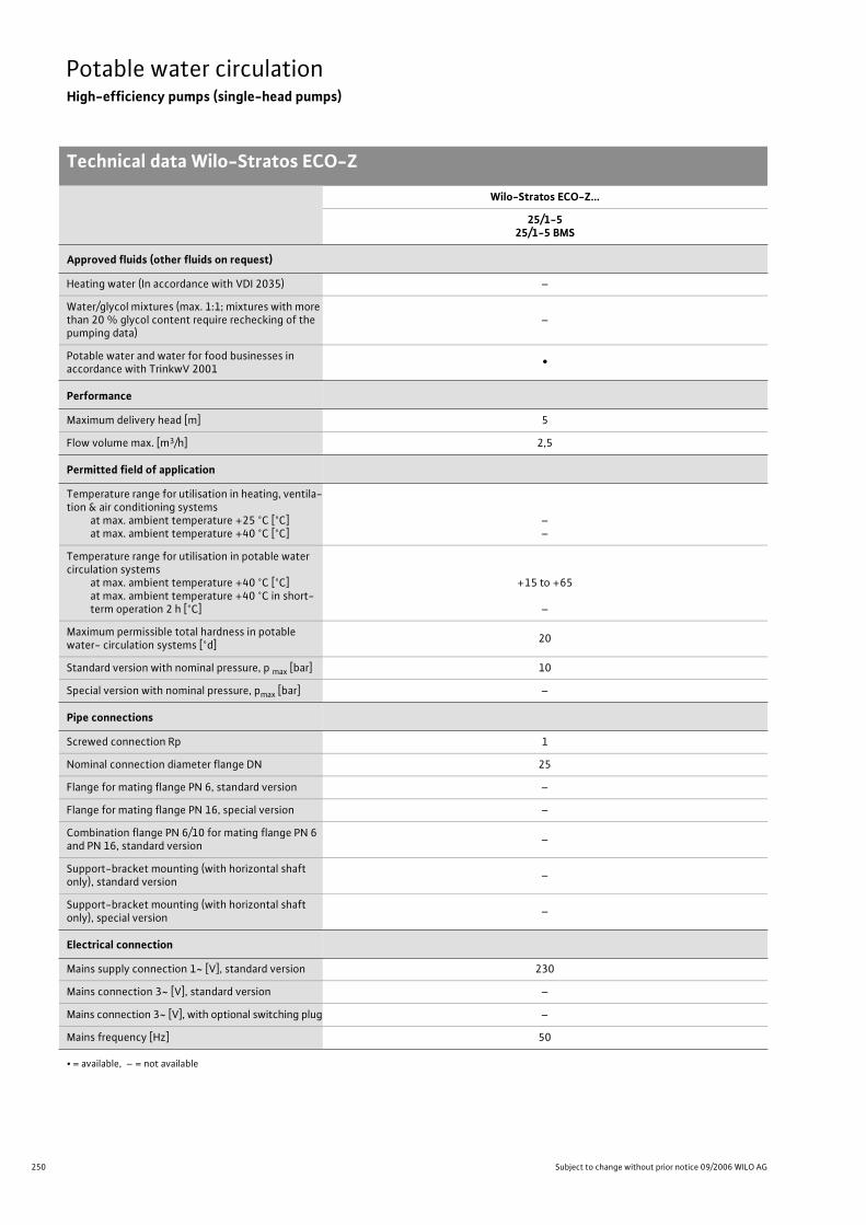
250 Subject to change without prior notice 09/2006 WILO AG
Potable water circulationHigh-efficiency pumps (single-head pumps)
Technical data Wilo-Stratos ECO-Z
Wilo-Stratos ECO-Z...
25/1-525/1-5 BMS
Approved fluids (other fluids on request)
Heating water (In accordance with VDI 2035) –
Water/glycol mixtures (max. 1:1; mixtures with more than 20 % glycol content require rechecking of the pumping data)
–
Potable water and water for food businesses in accordance with TrinkwV 2001
•
Performance
Maximum delivery head [m] 5
Flow volume max. [m3/h] 2,5
Permitted field of application
Temperature range for utilisation in heating, ventila-tion & air conditioning systems
at max. ambient temperature +25 °C [°C]at max. ambient temperature +40 °C [°C]
––
Temperature range for utilisation in potable water circulation systems
at max. ambient temperature +40 °C [°C]at max. ambient temperature +40 °C in short-term operation 2 h [°C]
+15 to +65
–
Maximum permissible total hardness in potable water- circulation systems [°d]
20
Standard version with nominal pressure, p max [bar] 10
Special version with nominal pressure, pmax [bar] –
Pipe connections
Screwed connection Rp 1
Nominal connection diameter flange DN 25
Flange for mating flange PN 6, standard version –
Flange for mating flange PN 16, special version –
Combination flange PN 6/10 for mating flange PN 6 and PN 16, standard version
–
Support-bracket mounting (with horizontal shaft only), standard version
–
Support-bracket mounting (with horizontal shaft only), special version
–
Electrical connection
Mains supply connection 1~ [V], standard version 230
Mains connection 3~ [V], standard version –
Mains connection 3~ [V], with optional switching plug –
Mains frequency [Hz] 50
• = available, – = not available
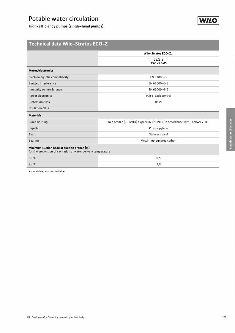
251
Potable water circulationHigh-efficiency pumps (single-head pumps)
Technical data Wilo-Stratos ECO-Z
Wilo Catalogue A1 - Circulating pumps in glandless design
Hea
tin
g, A
ir-c
on
dit
ion
ing
, C
oo
ling
Po
tab
le w
ater
cir
cula
tio
nSo
lar
ther
mal
Serv
ice/
Acc
esso
ries
, Sys
tem
sSw
itch
gea
rs a
nd
Co
ntr
ol
Dev
ices
P
um
p M
anag
emen
t S y
stem
s
Motor/electronics
Electromagnetic compatibility EN 61800-3
Emitted interference EN 61000-6-3
Immunity to interference EN 61000-6-2
Power electronics Pulse-pack control
Protection class IP 44
Insulation class F
Materials
Pump housing Red bronze (CC 491K) as per DIN EN 1982, in accordance with TrinkwV 2001
Impeller Polypropylene
Shaft Stainless steel
Bearing Metal-impregnated carbon
Minimum suction head at suction branch [m] for the prevention of cavitation at water delivery temperature
50 °C 0,5
95 °C 3,0
Wilo-Stratos ECO-Z...
25/1-525/1-5 BMS
• = available, – = not available
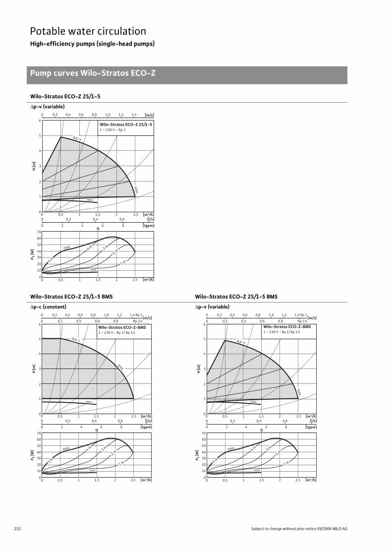
252 Subject to change without prior notice 09/2006 WILO AG
Potable water circulationHigh-efficiency pumps (single-head pumps)
Pump curves Wilo-Stratos ECO-Z
Wilo-Stratos ECO-Z 25/1-5
p-v (variable)
Wilo-Stratos ECO-Z 25/1-5 BMS Wilo-Stratos ECO-Z 25/1-5 BMS
p-c (constant) p-v (variable)
max.
H [m
]
0
4
5
6
2
1
3
0 0,5
0 0,2 0,4 0,6
0 2 4 6 8
1 1,5 2 2,5
[m³/h]1,51 2,520 0,5
[m³/h][l/s]
[lgpm]
0
40
30
20
10
50
60
70
P 1 [W
]
Wilo-Stratos ECO-Z 25/1-51 ~ 230 V - Rp 1
Q
4 m 3 m
2 m
1 m
p-v
ma
x.
min.
min.
5 m
[m/s]0,20 0,4 0,6 0,8 1,0 1,2 1,4
max.
H [m
]
0
4
5
6
2
1
3
[m/s]0 0,8 0,2 0,4
0,2 0 0,4 0,6 0,8 1,0 1,2 1,4
0,6
0 0,5
0 0,2 0,4 0,6
0 2 4 6 8
1 1,5 2 2,5
[m³/h]1,5 1 2,5 2 0 0,5
[m³/h][l/s]
[lgpm]
0
40
30
20
10
50
60
70
P 1 [W
]
Q
4 m
3 m
2 m
1 m
p-c
max.
min.
min.
5 m
Wilo-Stratos ECO-Z-BMS 1 ~ 230 V - Rp 1/ Rp 1¼
Rp 1¼
Rp 1
max.
H [m
]
0
4
5
6
2
1
3
[m/s]0 0,8 0,2 0,4
0,2 0 0,4 0,6 0,8 1,0 1,2 1,4
0,6
0 0,5
0 0,2 0,4 0,6
0 2 4 6 8
1 1,5 2 2,5
[m³/h]1,5 1 2,5 2 0 0,5
[m³/h][l/s]
[lgpm]
0
40
30
20
10
50
60
70
P 1 [W
]
Q
4 m
3 m
2 m
1 m
p-v
ma
x.
min.
min.
5 m
Wilo-Stratos ECO-Z-BMS 1 ~ 230 V - Rp 1/ Rp 1¼
Rp 1¼
Rp 1
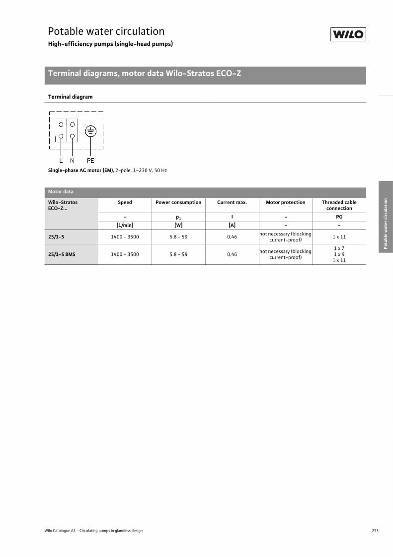
253
Potable water circulationHigh-efficiency pumps (single-head pumps)
Terminal diagrams, motor data Wilo-Stratos ECO-Z
Wilo Catalogue A1 - Circulating pumps in glandless design
Hea
tin
g, A
ir-c
on
dit
ion
ing
, C
oo
ling
Po
tab
le w
ater
cir
cula
tio
nSo
lar
ther
mal
Serv
ice/
Acc
esso
ries
, Sys
tem
sSw
itch
gea
rs a
nd
Co
ntr
ol
Dev
ices
P
um
p M
anag
emen
t S y
stem
s
Terminal diagram
Single-phase AC motor (EM), 2-pole, 1~230 V, 50 Hz
Motor data
Wilo-Stratos ECO-Z...
Speed Power consumption Current max. Motor protection Threaded cable connection
- p1 I - PG
[1/min] [W] [A] - -
25/1-5 1400 - 3500 5.8 - 59 0,46not necessary (blocking
current-proof)1 x 11
25/1-5 BMS 1400 - 3500 5.8 - 59 0,46not necessary (blocking
current-proof)
1 x 7 1 x 9
1 x 11
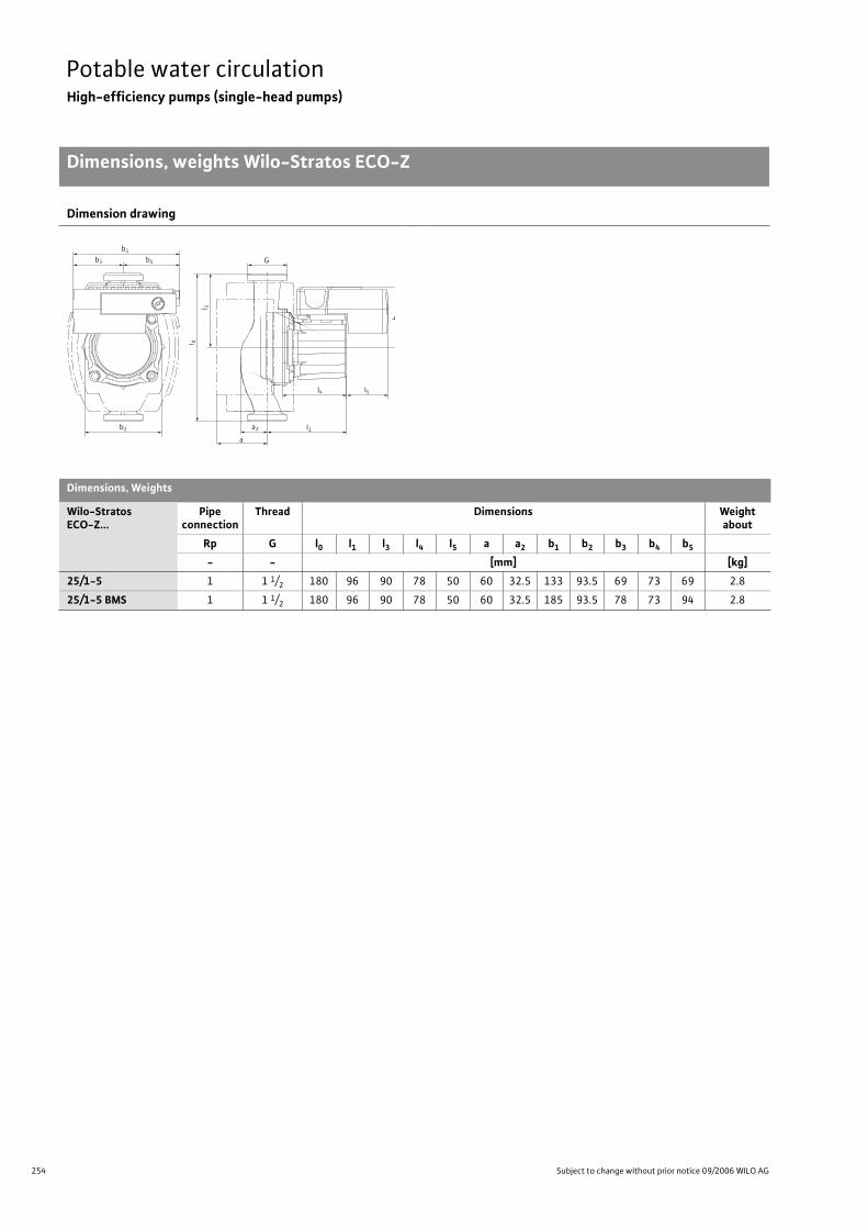
254 Subject to change without prior notice 09/2006 WILO AG
Potable water circulationHigh-efficiency pumps (single-head pumps)
Dimensions, weights Wilo-Stratos ECO-Z
Dimension drawing
Dimensions, Weights
Wilo-Stratos ECO-Z...
Pipe connection
Thread Dimensions Weight about
Rp G l0 l1 l3 l4 l5 a a2 b1 b2 b3 b4 b5
- - [mm] [kg]
25/1-5 1 1 1/2 180 96 90 78 50 60 32.5 133 93.5 69 73 69 2.8
25/1-5 BMS 1 1 1/2 180 96 90 78 50 60 32.5 185 93.5 78 73 94 2.8
G
a
b1
b3
b2 a2
b5
I4 I5
I1
I 0
l 3
b4

255
Potable water circulationHigh-efficiency pumps (single-head pumps)
Wilo Catalogue A1 - Circulating pumps in glandless design
Hea
tin
g, A
ir-c
on
dit
ion
ing
, C
oo
ling
Po
tab
le w
ater
cir
cula
tio
nSo
lar
ther
mal
Serv
ice/
Acc
esso
ries
, Sys
tem
sSw
itch
gea
rs a
nd
Co
ntr
ol
Dev
ices
P
um
p M
anag
emen
t S y
stem
s
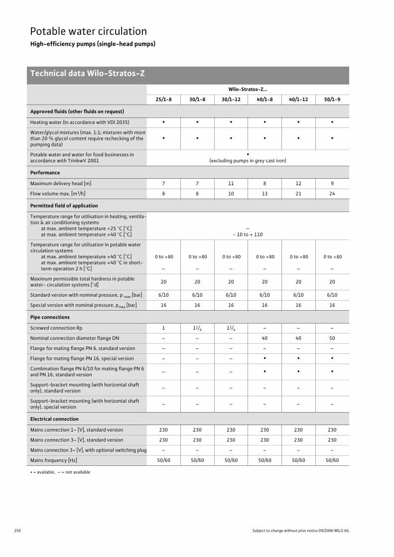
256 Subject to change without prior notice 09/2006 WILO AG
Potable water circulationHigh-efficiency pumps (single-head pumps)
Technical data Wilo-Stratos-Z
Wilo-Stratos-Z…
25/1-8 30/1-8 30/1-12 40/1-8 40/1-12 50/1-9
Approved fluids (other fluids on request)
Heating water (In accordance with VDI 2035) • • • • • •
Water/glycol mixtures (max. 1:1; mixtures with more than 20 % glycol content require rechecking of the pumping data)
• • • • • •
Potable water and water for food businesses in accordance with TrinkwV 2001
•(excluding pumps in grey cast iron)
Performance
Maximum delivery head [m] 7 7 11 8 12 9
Flow volume max. [m3/h] 8 8 10 13 21 24
Permitted field of application
Temperature range for utilisation in heating, ventila-tion & air conditioning systems
at max. ambient temperature +25 °C [°C]at max. ambient temperature +40 °C [°C]
–- 10 to + 110
Temperature range for utilisation in potable water circulation systems
at max. ambient temperature +40 °C [°C]at max. ambient temperature +40 °C in short-term operation 2 h [°C]
0 to +80
–
0 to +80
–
0 to +80
–
0 to +80
–
0 to +80
–
0 to +80
–
Maximum permissible total hardness in potable water- circulation systems [°d]
20 20 20 20 20 20
Standard version with nominal pressure, p max [bar] 6/10 6/10 6/10 6/10 6/10 6/10
Special version with nominal pressure, pmax [bar] 16 16 16 16 16 16
Pipe connections
Screwed connection Rp 1 11/4 11/4 – – –
Nominal connection diameter flange DN – – – 40 40 50
Flange for mating flange PN 6, standard version – – – – – –
Flange for mating flange PN 16, special version – – – • • •
Combination flange PN 6/10 for mating flange PN 6 and PN 16, standard version
– – – • • •
Support-bracket mounting (with horizontal shaft only), standard version
– – – – – –
Support-bracket mounting (with horizontal shaft only), special version
– – – – – –
Electrical connection
Mains connection 1~ [V], standard version 230 230 230 230 230 230
Mains connection 3~ [V], standard version 230 230 230 230 230 230
Mains connection 3~ [V], with optional switching plug – – – – – –
Mains frequency [Hz] 50/60 50/60 50/60 50/60 50/60 50/60
• = available, – = not available
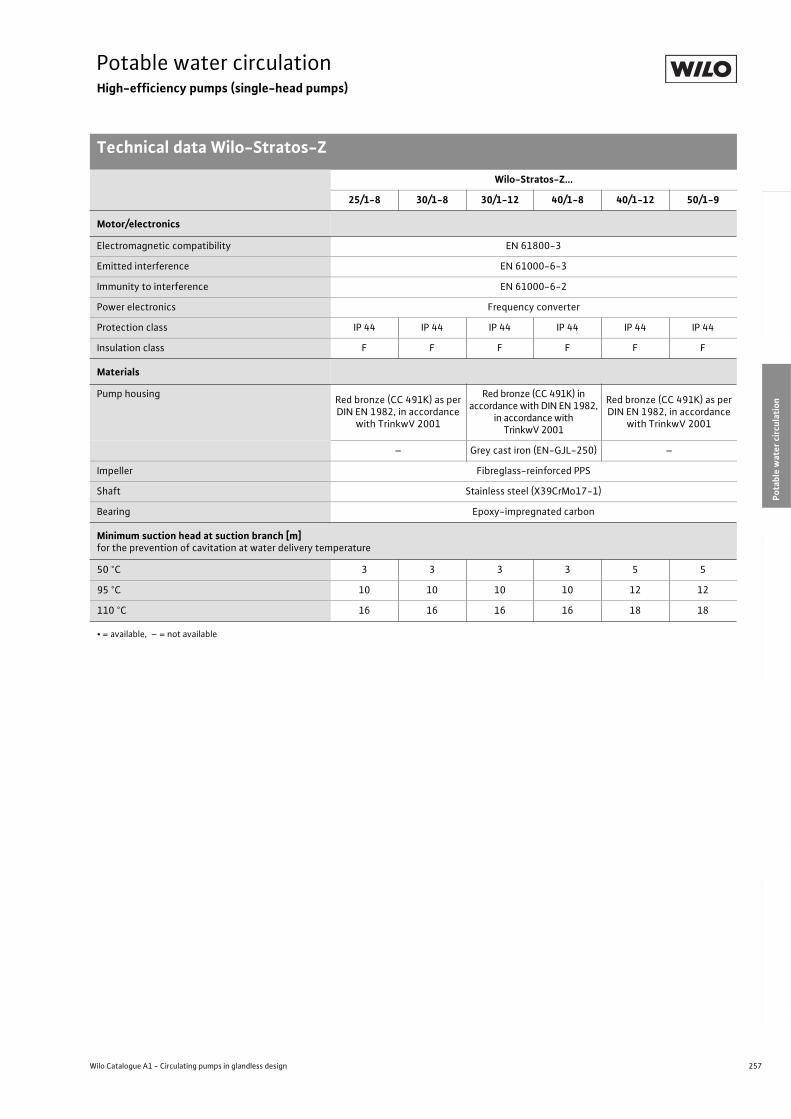
257
Potable water circulationHigh-efficiency pumps (single-head pumps)
Technical data Wilo-Stratos-Z
Wilo Catalogue A1 - Circulating pumps in glandless design
Hea
tin
g, A
ir-c
on
dit
ion
ing
, C
oo
ling
Po
tab
le w
ater
cir
cula
tio
nSo
lar
ther
mal
Serv
ice/
Acc
esso
ries
, Sys
tem
sSw
itch
gea
rs a
nd
Co
ntr
ol
Dev
ices
P
um
p M
anag
emen
t S y
stem
s
Motor/electronics
Electromagnetic compatibility EN 61800-3
Emitted interference EN 61000-6-3
Immunity to interference EN 61000-6-2
Power electronics Frequency converter
Protection class IP 44 IP 44 IP 44 IP 44 IP 44 IP 44
Insulation class F F F F F F
Materials
Pump housingRed bronze (CC 491K) as per DIN EN 1982, in accordance
with TrinkwV 2001
Red bronze (CC 491K) in accordance with DIN EN 1982,
in accordance with TrinkwV 2001
Red bronze (CC 491K) as per DIN EN 1982, in accordance
with TrinkwV 2001
– Grey cast iron (EN-GJL-250) –
Impeller Fibreglass-reinforced PPS
Shaft Stainless steel (X39CrMo17-1)
Bearing Epoxy-impregnated carbon
Minimum suction head at suction branch [m] for the prevention of cavitation at water delivery temperature
50 °C 3 3 3 3 5 5
95 °C 10 10 10 10 12 12
110 °C 16 16 16 16 18 18
Wilo-Stratos-Z…
25/1-8 30/1-8 30/1-12 40/1-8 40/1-12 50/1-9
• = available, – = not available
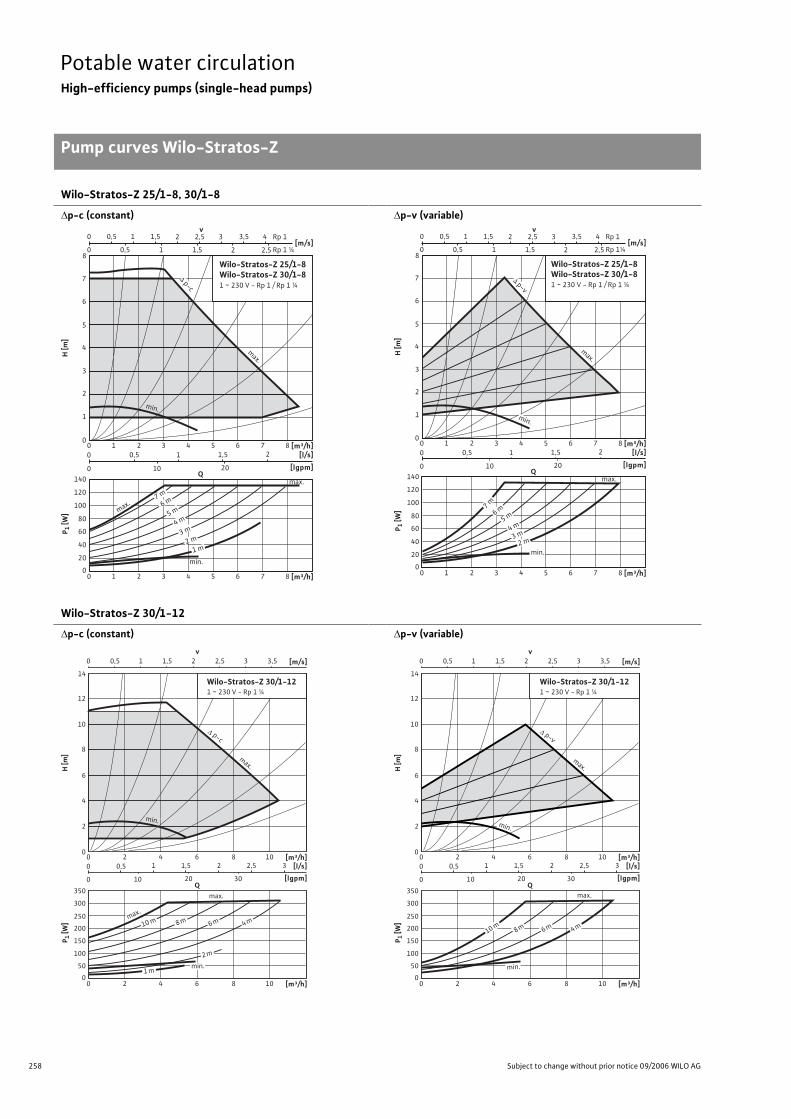
258 Subject to change without prior notice 09/2006 WILO AG
Potable water circulationHigh-efficiency pumps (single-head pumps)
Pump curves Wilo-Stratos-Z
Wilo-Stratos-Z 25/1-8, 30/1-8
p-c (constant) p-v (variable)
Wilo-Stratos-Z 30/1-12
p-c (constant) p-v (variable)
0
4
5
7
6
8
2
1
3
H[m
]
Q
[m³/h] [l/s]
[lgpm]
P 1 [W
]
0
80
60
40
20
100
120
140
Wilo-Stratos-Z 25/1-8Wilo-Stratos-Z 30/1-81 ~ 230 V - Rp 1 / Rp 1 ¼
6 8 4 0 2 5 7 3 1
[m³/h]6 8 4 0 2 5 7 3 1
2
10 20
1,5 1 0,5
0
0
[m/s]2 1 0 2,5 1,5 0,5
v2 1 0 2,5 3 4 1,5 Rp 1
Rp 1 ¼
3,5 0,5
max.
max.
1 m 2 m
3 m 4 m
5 m
6 m
7 m
min.
p-c
max.
min.
0
4
5
7
6
8
2
1
3
H[m
]
Q
[l/s]
[lgpm]
P 1 [W
]
0
80
60
40
20
100
120
140
2
10 20
1,5 1 0,5
0
0
[m/s]2 1 0 2,5 1,5 0,5
v2 1 0 2,5 3 4 1,5 Rp 1
Rp 1¼
3,5 0,5
Wilo-Stratos-Z 25/1-8Wilo-Stratos-Z 30/1-81 ~ 230 V - Rp 1 / Rp 1 ¼
[m³/h] 6 8 4 0 2 5 7 3 1
[m³/h] 6 8 4 0 2 5 7 3 1
max.
min.
2 m 3 m 4 m
5 m 6 m
7 m
min.
max.
p-v
v0 1 2 31,50,5 2,5 3,5 [m/s]
0
8
10
12
14
4
2
6
H [m
]
[m³/h][l/s]
[lgpm]
P 1 [W
]
0
250
200
100
150
50
300
350
Wilo-Stratos-Z 30/1-121 ~ 230 V - Rp 1 ¼
80 4 1062
[m³/h]80 4 1062
1 1,5 2 32,5
10 20 30
0,5
0
0
Qmax.
max.
10 m 8 m 6 m 4 m
2 m
1 mmin.
min.
p-c
max.
v0 1 2 31,50,5 2,5 3,5 [m/s]
0
8
10
12
14
4
2
6
H [m
]
[m³/h][l/s]
[lgpm]
P 1 [W
]
0
250
200
100
150
50
300
350
Wilo-Stratos-Z 30/1-121 ~ 230 V - Rp 1 ¼
80 4 1062
[m³/h]80 4 1062
1 1,5 2 32,5
10 20 30
0,5
0
0
Qmax.
10 m8 m 6 m 4 m
min.
min.
p-v
max.
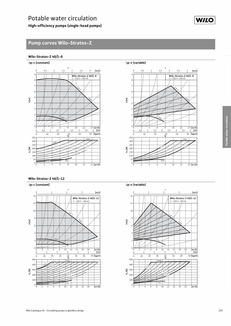
259
Potable water circulationHigh-efficiency pumps (single-head pumps)
Pump curves Wilo-Stratos-Z
Wilo Catalogue A1 - Circulating pumps in glandless design
Hea
tin
g, A
ir-c
on
dit
ion
ing
, C
oo
ling
Po
tab
le w
ater
cir
cula
tio
nSo
lar
ther
mal
Serv
ice/
Acc
esso
ries
, Sys
tem
sSw
itch
gea
rs a
nd
Co
ntr
ol
Dev
ices
P
um
p M
anag
emen
t S y
stem
s
Wilo-Stratos-Z 40/1-8
p-c (constant) p-v (variable)
Wilo-Stratos-Z 40/1-12
p-c (constant) p-v (variable)
0
8
9
4
2
6
7
3
1
5
H [m
]
[m³/h][l/s]
[lgpm]
Wilo-Stratos-Z 40/1-81 ~ 230 V - DN 40
1280 4 10 1462
[m³/h]1280 4 10 1462
1,51 2,52 43,53
10 20 30 40 50
0,5
0
0
Q
P 1 [W
]
0
250
200
100
150
50
300
350
v0 1 2 31,50,5 2,5 [m/s]
max.
max.
7 m 6 m 5 m 4 m 3 m
2 m
1 m min.
p-c
min.
max.
0
8
9
4
2
6
7
3
1
5
H [m
][m³/h]
[l/s]
[lgpm]
Wilo-Stratos-Z 40/1-81 ~ 230 V - DN 40
1280 4 10 1462
[m³/h]1280 4 10 1462
1,51 2,52 43,53
10 20 30 40 50
0,5
0
0
Q
P 1 [W
]
0
250
200
100
150
50
300
350
v0 1 2 31,50,5 2,5 [m/s]
min.
max.
7 m 6 m 5 m 4 m 3 m
min.
p-v
max.
v0 1 2 3 [m/s]
0
8
10
12
14
4
2
6
H [m
]
[m³/h][l/s]
[lgpm]
P 1 [W
]
0
300
200
100
400
500
Wilo-Stratos-Z 40/1-121 ~ 230 V - DN 40
12 16 1880 4 10 1462
12 16 1880 4 10 1462 [m³/h]
2 3 4 5
10 20 30 40 50 60 70
1
0
0
Qmax.
9 m8 m
10 m11 m
7 m6 m
5 m4 m
3 m2 m
1 m
max.
min.
12 m
p-c
min.
max.
v0 1 2 3 [m/s]
0
8
10
12
14
4
2
6
H [m
]
[l/s]
[lgpm]
P 1 [W
]
0
300
200
100
400
500
Wilo-Stratos-Z 40/1-121 ~ 230 V - DN 40
2 3 4 5
10 20 30 40 50 60 70
1
0
0
Q
[m³/h]12 16 1880 4 10 1462
12 16 1880 4 10 1462 [m³/h]
max.
9 m8 m10 m12 m
11 m
7 m6 m
5 m4 m
min.
max.
min.
p-v
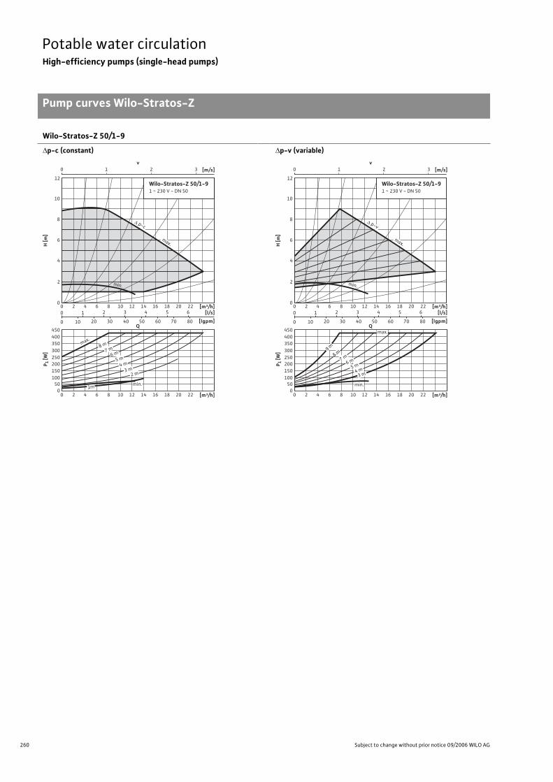
260 Subject to change without prior notice 09/2006 WILO AG
Potable water circulationHigh-efficiency pumps (single-head pumps)
Pump curves Wilo-Stratos-Z
Wilo-Stratos-Z 50/1-9
p-c (constant) p-v (variable)
v0 1 2 3 [m/s]
0
8
10
12
4
2
6
H [m
]
[m³/h][l/s]
[lgpm]
P 1 [W
]
0
350
100
50
400
450
200
150
250
300
12 16 18 20 2280 4 10 1462
12 16 18 20 2280 4 10 1462
2 3 4 5 6
10 20 30 40 50 60 70 80
1
0
0
Q
[m³/h]
Wilo-Stratos-Z 50/1-91 ~ 230 V - DN 50
max.
8 m
7 m
min.
6 m
5 m
4 m
3 m2 m
1m
min.
p-c
max.
v0 1 2 3 [m/s]
0
8
10
12
4
2
6
H [m
]
[l/s]
[lgpm]
P 1 [W
]
0
350
100
50
400
450
200
150
250
300
2 3 4 5 6
10 20 30 40 50 60 70 80
1
0
0
Q
Wilo-Stratos-Z 50/1-91 ~ 230 V - DN 50
[m³/h]12 16 18 20 2280 4 10 1462
12 16 18 20 2280 4 10 1462 [m³/h]
min.
max.
9 m
8 m
7 m6 m
5 m4 m
3 m
min.
p-v
max.
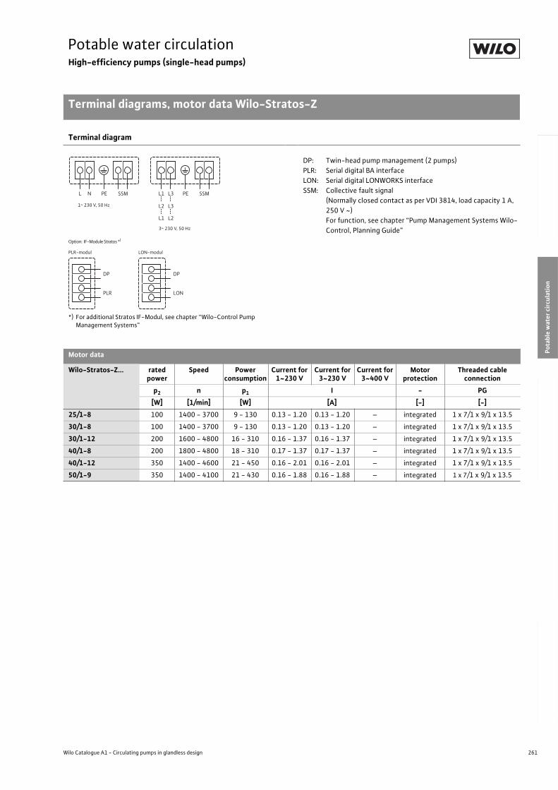
261
Potable water circulationHigh-efficiency pumps (single-head pumps)
Terminal diagrams, motor data Wilo-Stratos-Z
Wilo Catalogue A1 - Circulating pumps in glandless design
Hea
tin
g, A
ir-c
on
dit
ion
ing
, C
oo
ling
Po
tab
le w
ater
cir
cula
tio
nSo
lar
ther
mal
Serv
ice/
Acc
esso
ries
, Sys
tem
sSw
itch
gea
rs a
nd
Co
ntr
ol
Dev
ices
P
um
p M
anag
emen
t S y
stem
s
Terminal diagram
*) For additional Stratos IF-Modul, see chapter “Wilo-Control Pump Management Systems”
DP: Twin-head pump management (2 pumps)
PLR: Serial digital BA interface
LON: Serial digital LONWORKS interface
SSM: Collective fault signal
(Normally closed contact as per VDI 3814, load capacity 1 A,
250 V ~)
For function, see chapter “Pump Management Systems Wilo-
Control, Planning Guide”
Motor data
Wilo-Stratos-Z... rated power
Speed Power consumption
Current for 1~230 V
Current for 3~230 V
Current for 3~400 V
Motor protection
Threaded cable connection
p2 n p1 I - PG
[W] [1/min] [W] [A] [-] [-]
25/1-8 100 1400 - 3700 9 - 130 0.13 - 1.20 0.13 - 1.20 – integrated 1 x 7/1 x 9/1 x 13.5
30/1-8 100 1400 - 3700 9 - 130 0.13 - 1.20 0.13 - 1.20 – integrated 1 x 7/1 x 9/1 x 13.5
30/1-12 200 1600 - 4800 16 - 310 0.16 - 1.37 0.16 - 1.37 – integrated 1 x 7/1 x 9/1 x 13.5
40/1-8 200 1800 - 4800 18 - 310 0.17 - 1.37 0.17 - 1.37 – integrated 1 x 7/1 x 9/1 x 13.5
40/1-12 350 1400 - 4600 21 - 450 0.16 - 2.01 0.16 - 2.01 – integrated 1 x 7/1 x 9/1 x 13.5
50/1-9 350 1400 - 4100 21 - 430 0.16 - 1.88 0.16 - 1.88 – integrated 1 x 7/1 x 9/1 x 13.5
L N PE SSM L1 L3
L2 L3
L1 L2
PE SSM
DP
PLR
DP
LON
Option: IF-Module Stratos *)
PLR-modul LON-modul
1~ 230 V, 50 Hz
3~ 230 V, 50 Hz
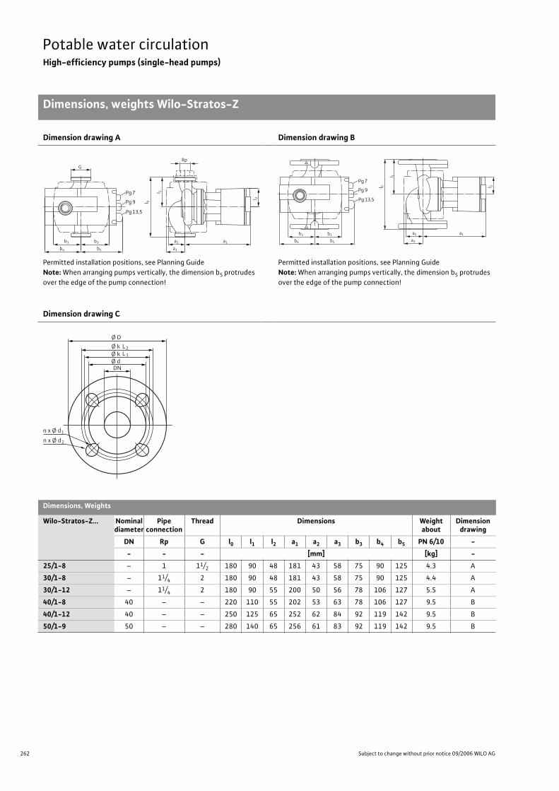
262 Subject to change without prior notice 09/2006 WILO AG
Potable water circulationHigh-efficiency pumps (single-head pumps)
Dimensions, weights Wilo-Stratos-Z
Dimension drawing A
Permitted installation positions, see Planning Guide
Note: When arranging pumps vertically, the dimension b5 protrudes
over the edge of the pump connection!
Dimension drawing B
Permitted installation positions, see Planning Guide
Note: When arranging pumps vertically, the dimension b5 protrudes
over the edge of the pump connection!
Dimension drawing C
Dimensions, Weights
Wilo-Stratos-Z... Nominal diameter
Pipe connection
Thread Dimensions Weight about
Dimensiondrawing
DN Rp G l0 l1 l2 a1 a2 a3 b3 b4 b5 PN 6/10 -
- - - [mm] [kg] -
25/1-8 – 1 11/2 180 90 48 181 43 58 75 90 125 4.3 A
30/1-8 – 11/4 2 180 90 48 181 43 58 75 90 125 4.4 A
30/1-12 – 11/4 2 180 90 55 200 50 56 78 106 127 5.5 A
40/1-8 40 – – 220 110 55 202 53 63 78 106 127 9.5 B
40/1-12 40 – – 250 125 65 252 62 84 92 119 142 9.5 B
50/1-9 50 – – 280 140 65 256 61 83 92 119 142 9.5 B
l 0
l 2
a2 a1
Pg 7
b3b3
G
b5b4
Pg 9
Pg 13,5
a3
Rpl 1
l 0 l 2
a2 a1
Pg 7
b3b3
b5b4
Pg 9
Pg 13,5
a3
l 1
Ø D
n x Ø d
Ø k
DN
L2
Ø k Ø d
L 1
1
n x Ø d 2
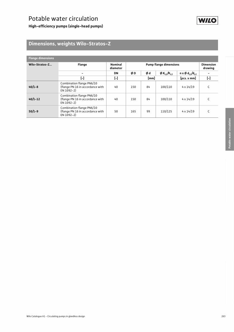
263
Potable water circulationHigh-efficiency pumps (single-head pumps)
Dimensions, weights Wilo-Stratos-Z
Wilo Catalogue A1 - Circulating pumps in glandless design
Hea
tin
g, A
ir-c
on
dit
ion
ing
, C
oo
ling
Po
tab
le w
ater
cir
cula
tio
nSo
lar
ther
mal
Serv
ice/
Acc
esso
ries
, Sys
tem
sSw
itch
gea
rs a
nd
Co
ntr
ol
Dev
ices
P
um
p M
anag
emen
t S y
stem
s
Flange dimensions
Wilo-Stratos-Z... Flange Nominal diameter
Pump flange dimensions Dimension drawing
- DN Ø D Ø d Ø KL1/KL2 n x Ø dL1/dL2 -
[-] [-] [mm] [pcs. x mm] [-]
40/1-8Combination flange PN6/10(flange PN 16 in accordance with EN 1092-2)
40 150 84 100/110 4 x 14/19 C
40/1-12Combination flange PN6/10(flange PN 16 in accordance with EN 1092-2)
40 150 84 100/110 4 x 14/19 C
50/1-9Combination flange PN6/10(flange PN 16 in accordance with EN 1092-2)
50 165 99 110/125 4 x 14/19 C
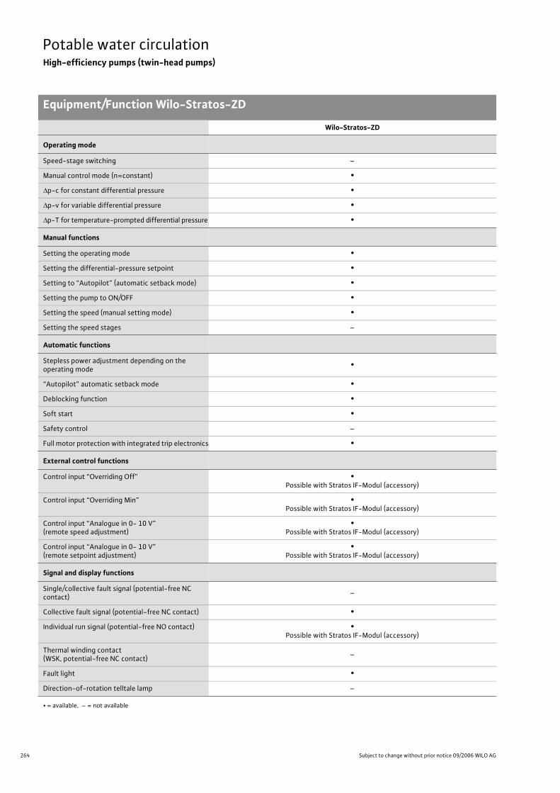
264 Subject to change without prior notice 09/2006 WILO AG
Potable water circulationHigh-efficiency pumps (twin-head pumps)
Equipment/Function Wilo-Stratos-ZD
Wilo-Stratos-ZD
Operating mode
Speed-stage switching –
Manual control mode (n=constant) •
p-c for constant differential pressure •
p-v for variable differential pressure •
p-T for temperature-prompted differential pressure •
Manual functions
Setting the operating mode •
Setting the differential-pressure setpoint •
Setting to “Autopilot” (automatic setback mode) •
Setting the pump to ON/OFF •
Setting the speed (manual setting mode) •
Setting the speed stages –
Automatic functions
Stepless power adjustment depending on the operating mode
•
“Autopilot” automatic setback mode •
Deblocking function •
Soft start •
Safety control –
Full motor protection with integrated trip electronics •
External control functions
Control input “Overriding Off” •Possible with Stratos IF-Modul (accessory)
Control input “Overriding Min” •Possible with Stratos IF-Modul (accessory)
Control input “Analogue in 0- 10 V” (remote speed adjustment)
•Possible with Stratos IF-Modul (accessory)
Control input “Analogue in 0- 10 V” (remote setpoint adjustment)
•Possible with Stratos IF-Modul (accessory)
Signal and display functions
Single/collective fault signal (potential-free NC contact)
–
Collective fault signal (potential-free NC contact) •
Individual run signal (potential-free NO contact) •Possible with Stratos IF-Modul (accessory)
Thermal winding contact (WSK, potential-free NC contact)
–
Fault light •
Direction-of-rotation telltale lamp –
• = available, – = not available
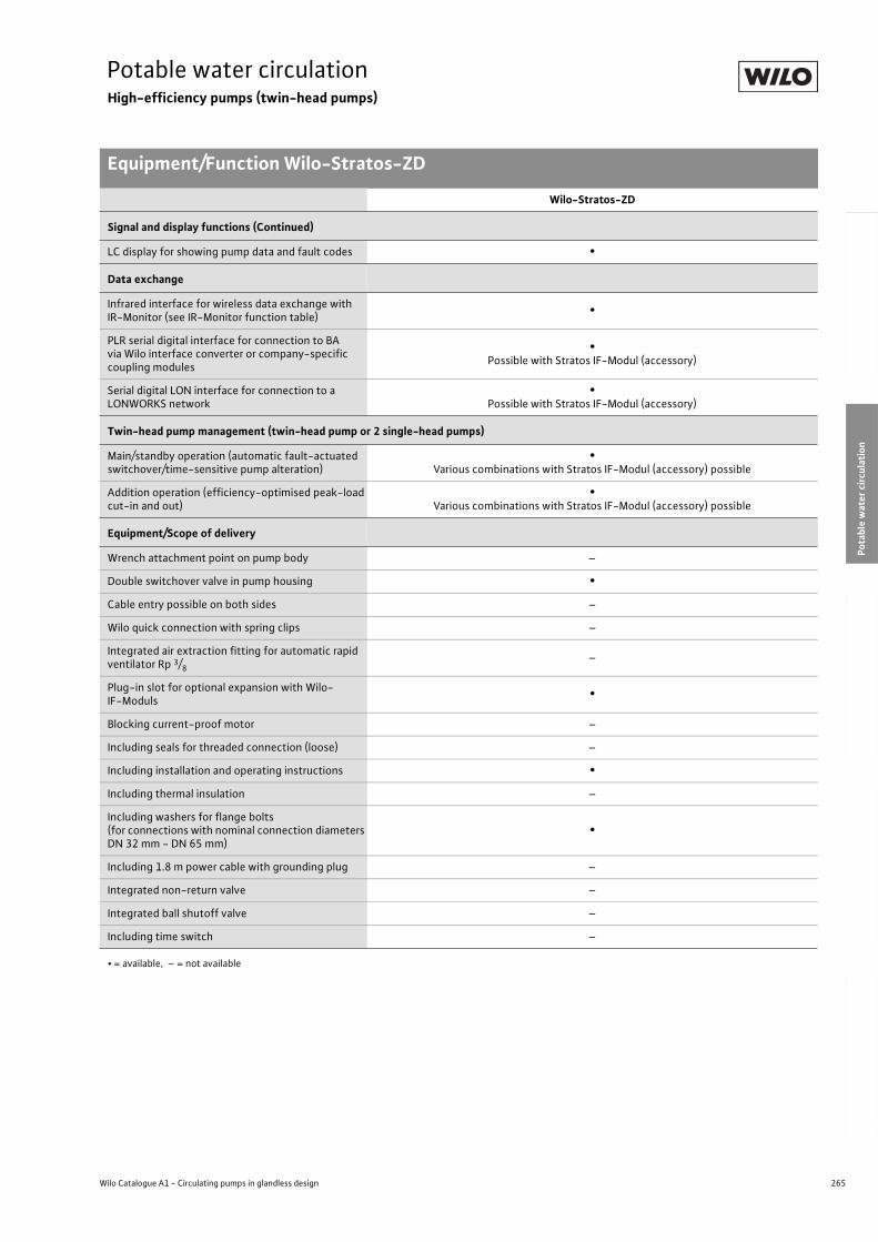
265
Potable water circulationHigh-efficiency pumps (twin-head pumps)
Equipment/Function Wilo-Stratos-ZD
Wilo Catalogue A1 - Circulating pumps in glandless design
Hea
tin
g, A
ir-c
on
dit
ion
ing
, C
oo
ling
Po
tab
le w
ater
cir
cula
tio
nSo
lar
ther
mal
Serv
ice/
Acc
esso
ries
, Sys
tem
sSw
itch
gea
rs a
nd
Co
ntr
ol
Dev
ices
P
um
p M
anag
emen
t S y
stem
s
Signal and display functions (Continued)
LC display for showing pump data and fault codes •
Data exchange
Infrared interface for wireless data exchange with IR-Monitor (see IR-Monitor function table)
•
PLR serial digital interface for connection to BA via Wilo interface converter or company-specific coupling modules
•Possible with Stratos IF-Modul (accessory)
Serial digital LON interface for connection to a LONWORKS network
•Possible with Stratos IF-Modul (accessory)
Twin-head pump management (twin-head pump or 2 single-head pumps)
Main/standby operation (automatic fault-actuated switchover/time-sensitive pump alteration)
•Various combinations with Stratos IF-Modul (accessory) possible
Addition operation (efficiency-optimised peak-load cut-in and out)
•Various combinations with Stratos IF-Modul (accessory) possible
Equipment/Scope of delivery
Wrench attachment point on pump body –
Double switchover valve in pump housing •
Cable entry possible on both sides –
Wilo quick connection with spring clips –
Integrated air extraction fitting for automatic rapid ventilator Rp 3/8
–
Plug-in slot for optional expansion with Wilo-IF-Moduls
•
Blocking current-proof motor –
Including seals for threaded connection (loose) –
Including installation and operating instructions •
Including thermal insulation –
Including washers for flange bolts (for connections with nominal connection diameters DN 32 mm - DN 65 mm)
•
Including 1.8 m power cable with grounding plug –
Integrated non-return valve –
Integrated ball shutoff valve –
Including time switch –
Wilo-Stratos-ZD
• = available, – = not available
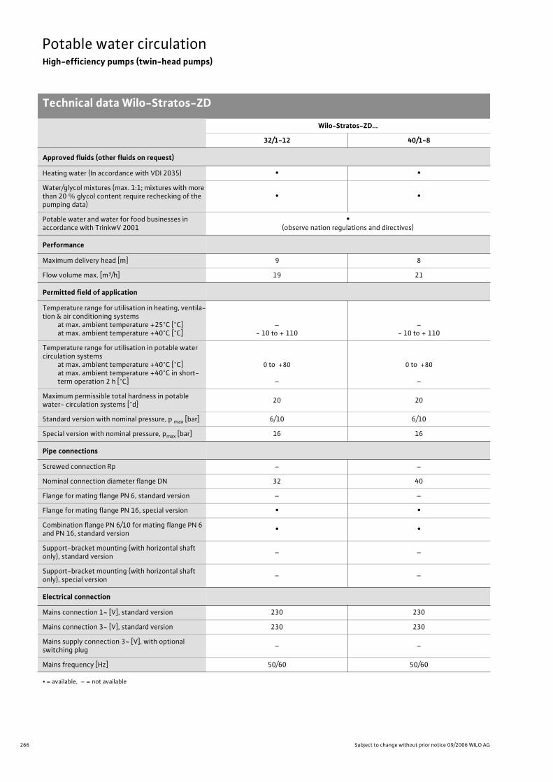
266 Subject to change without prior notice 09/2006 WILO AG
Potable water circulationHigh-efficiency pumps (twin-head pumps)
Technical data Wilo-Stratos-ZD
Wilo-Stratos-ZD...
32/1-12 40/1-8
Approved fluids (other fluids on request)
Heating water (In accordance with VDI 2035) • •
Water/glycol mixtures (max. 1:1; mixtures with more than 20 % glycol content require rechecking of the pumping data)
• •
Potable water and water for food businesses in accordance with TrinkwV 2001
•(observe nation regulations and directives)
Performance
Maximum delivery head [m] 9 8
Flow volume max. [m3/h] 19 21
Permitted field of application
Temperature range for utilisation in heating, ventila-tion & air conditioning systems
at max. ambient temperature +25°C [°C]at max. ambient temperature +40°C [°C]
–- 10 to + 110
–- 10 to + 110
Temperature range for utilisation in potable water circulation systems
at max. ambient temperature +40°C [°C]at max. ambient temperature +40°C in short-term operation 2 h [°C]
0 to +80
–
0 to +80
–
Maximum permissible total hardness in potable water- circulation systems [°d]
20 20
Standard version with nominal pressure, p max [bar] 6/10 6/10
Special version with nominal pressure, pmax [bar] 16 16
Pipe connections
Screwed connection Rp – –
Nominal connection diameter flange DN 32 40
Flange for mating flange PN 6, standard version – –
Flange for mating flange PN 16, special version • •
Combination flange PN 6/10 for mating flange PN 6 and PN 16, standard version
• •
Support-bracket mounting (with horizontal shaft only), standard version
– –
Support-bracket mounting (with horizontal shaft only), special version
– –
Electrical connection
Mains connection 1~ [V], standard version 230 230
Mains connection 3~ [V], standard version 230 230
Mains supply connection 3~ [V], with optional switching plug
– –
Mains frequency [Hz] 50/60 50/60
• = available, – = not available
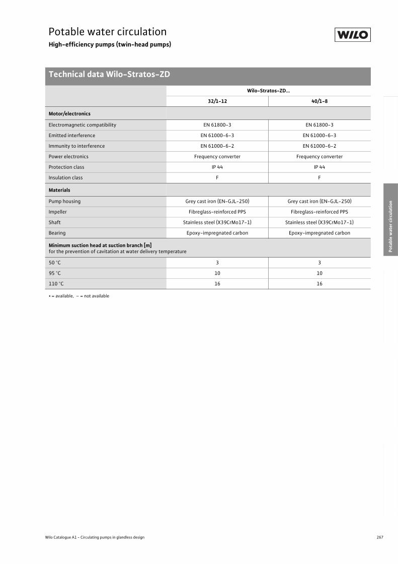
267
Potable water circulationHigh-efficiency pumps (twin-head pumps)
Technical data Wilo-Stratos-ZD
Wilo Catalogue A1 - Circulating pumps in glandless design
Hea
tin
g, A
ir-c
on
dit
ion
ing
, C
oo
ling
Po
tab
le w
ater
cir
cula
tio
nSo
lar
ther
mal
Serv
ice/
Acc
esso
ries
, Sys
tem
sSw
itch
gea
rs a
nd
Co
ntr
ol
Dev
ices
P
um
p M
anag
emen
t S y
stem
s
Motor/electronics
Electromagnetic compatibility EN 61800-3 EN 61800-3
Emitted interference EN 61000-6-3 EN 61000-6-3
Immunity to interference EN 61000-6-2 EN 61000-6-2
Power electronics Frequency converter Frequency converter
Protection class IP 44 IP 44
Insulation class F F
Materials
Pump housing Grey cast iron (EN-GJL-250) Grey cast iron (EN-GJL-250)
Impeller Fibreglass-reinforced PPS Fibreglass-reinforced PPS
Shaft Stainless steel (X39CrMo17-1) Stainless steel (X39CrMo17-1)
Bearing Epoxy-impregnated carbon Epoxy-impregnated carbon
Minimum suction head at suction branch [m] for the prevention of cavitation at water delivery temperature
50 °C 3 3
95 °C 10 10
110 °C 16 16
Wilo-Stratos-ZD...
32/1-12 40/1-8
• = available, – = not available
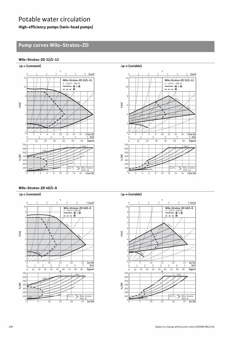
268 Subject to change without prior notice 09/2006 WILO AG
Potable water circulationHigh-efficiency pumps (twin-head pumps)
Pump curves Wilo-Stratos-ZD
Wilo-Stratos-ZD 32/1-12
p-c (constant) p-v (variable)
Wilo-Stratos-ZD 40/1-8
p-c (constant) p-v (variable)
v0 1 2 3 4 5 6 [m/s]
0
8
10
12
4
2
6
H [m
]
[m³/h][l/s]
[lgpm]
P 1 [W
]
0
300
200
100
400
500
600
700
12 16 1880 4 10 1462
12 16 1880 4 10 1462 [m³/h]
2 3 4 5
10 20 30 40 50 60
1
0
0
P1- Wilo-Stratos 32/1-12
Wilo-Stratos-ZD 32/1-121 ~ 230 V - DN 32
+
max.
1 m
9 m 8 m 7 m 6 m 5 m 4 m
2 m
3 m
min.
max.
p-c
max.
min.
v0 1 2 3 4 5 6 [m/s]
0
8
10
12
4
2
6
H [m
]
[m³/h][l/s]
[lgpm]
P 1 [W
]
0
300
200
100
400
500
600
700
12 16 1880 4 10 1462
12 16 1880 4 10 1462 [m³/h]
2 3 4 5
10 20 30 40 50 60
1
0
0
P1- Wilo-Stratos 32/1-12
Wilo-Stratos-ZD 32/1-121 ~ 230 V - DN 32
+
max.
min.
8 m 7 m 6 m 5 m 4 m
p-v
max.
min.
v0 1 2 3 4 5 6 [m/s]
0
8
10
4
2
6
7
9
3
1
5
H [m
]
[m³/h][l/s]
[lgpm]
P 1 [W
]
0
300
200
100
400
500
600
700
200 10 25155
2 3 4 5 6 7
10 20 30 40 50 60 70 80 90
1
0
0
[m³/h]200 10 25155
Wilo-Stratos-ZD 40/1-81 ~ 230 V - DN 40
+
Q
P1 Wilo-Stratos 40/1-8
max.
min.
max.
3 m
2 m
1 m
4 m5 m6 m7 m8 m
p-c
max.
min.
v0 1 2 3 4 5 6 [m/s]
0
8
10
4
2
6
7
9
3
1
5
H [m
]
[m³/h][l/s]
[lgpm]
P 1 [W
]
0
300
200
100
400
500
600
700
200 10 25155
2 3 4 5 6 7
10 20 30 40 50 60 70 80 90
1
0
0
[m³/h]200 10 25155
Wilo-Stratos-ZD 40/1-81 ~ 230 V - DN 40
+
Q
P1 Wilo-Stratos 40/1-8min.
3 m4 m5 m6 m7 m
max.
p-v
max.
min.
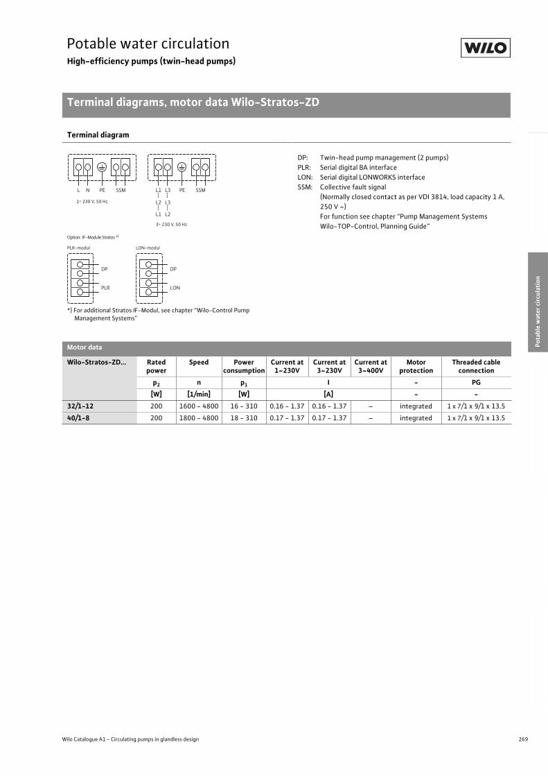
269
Potable water circulationHigh-efficiency pumps (twin-head pumps)
Terminal diagrams, motor data Wilo-Stratos-ZD
Wilo Catalogue A1 - Circulating pumps in glandless design
Hea
tin
g, A
ir-c
on
dit
ion
ing
, C
oo
ling
Po
tab
le w
ater
cir
cula
tio
nSo
lar
ther
mal
Serv
ice/
Acc
esso
ries
, Sys
tem
sSw
itch
gea
rs a
nd
Co
ntr
ol
Dev
ices
P
um
p M
anag
emen
t S y
stem
s
Terminal diagram
*) For additional Stratos IF-Modul, see chapter “Wilo-Control Pump Management Systems”
DP: Twin-head pump management (2 pumps)
PLR: Serial digital BA interface
LON: Serial digital LONWORKS interface
SSM: Collective fault signal
(Normally closed contact as per VDI 3814, load capacity 1 A,
250 V ~)
For function see chapter “Pump Management Systems
Wilo-TOP-Control, Planning Guide”
Motor data
Wilo-Stratos-ZD... Rated power
Speed Power consumption
Current at 1~230V
Current at 3~230V
Current at 3~400V
Motor protection
Threaded cable connection
p2 n p1 I - PG
[W] [1/min] [W] [A] - -
32/1-12 200 1600 - 4800 16 - 310 0.16 - 1.37 0.16 - 1.37 – integrated 1 x 7/1 x 9/1 x 13.5
40/1-8 200 1800 - 4800 18 - 310 0.17 - 1.37 0.17 - 1.37 – integrated 1 x 7/1 x 9/1 x 13.5
L N PE SSM L1 L3
L2 L3
L1 L2
PE SSM
DP
PLR
DP
LON
Option: IF-Module Stratos *)
PLR-modul LON-modul
1~ 230 V, 50 Hz
3~ 230 V, 50 Hz
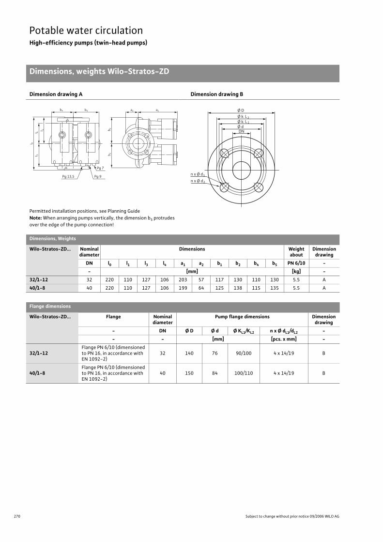
270 Subject to change without prior notice 09/2006 WILO AG
Potable water circulationHigh-efficiency pumps (twin-head pumps)
Dimensions, weights Wilo-Stratos-ZD
Dimension drawing A
Permitted installation positions, see Planning Guide
Note: When arranging pumps vertically, the dimension b5 protrudes
over the edge of the pump connection!
Dimension drawing B
Dimensions, Weights
Wilo-Stratos-ZD... Nominal diameter
Dimensions Weight about
Dimension drawing
DN l0 l1 l3 l4 a1 a2 b1 b2 b4 b5 PN 6/10 -
- [mm] [kg] -
32/1-12 32 220 110 127 106 203 57 117 130 110 130 5.5 A
40/1-8 40 220 110 127 106 199 64 125 138 115 135 5.5 A
Flange dimensions
Wilo-Stratos-ZD... Flange Nominal diameter
Pump flange dimensions Dimension drawing
- DN Ø D Ø d Ø KL1/KL2 n x Ø dL1/dL2 -
- - [mm] [pcs. x mm] -
32/1-12Flange PN 6/10 (dimensioned to PN 16, in accordance with EN 1092-2)
32 140 76 90/100 4 x 14/19 B
40/1-8Flange PN 6/10 (dimensioned to PN 16, in accordance with EN 1092-2)
40 150 84 100/110 4 x 14/19 B
Pg 7
Pg 9Pg 13,5
a1b 2
b 1b5b4
l 0l 3
l 4
a2
l 1
Ø D
n x Ø d
Ø k
DN
L2
Ø k Ø d
L 1
1
n x Ø d 2

271
Potable water circulationHigh-efficiency pumps (twin-head pumps)
Wilo Catalogue A1 - Circulating pumps in glandless design
Hea
tin
g, A
ir-c
on
dit
ion
ing
, C
oo
ling
Po
tab
le w
ater
cir
cula
tio
nSo
lar
ther
mal
Serv
ice/
Acc
esso
ries
, Sys
tem
sSw
itch
gea
rs a
nd
Co
ntr
ol
Dev
ices
P
um
p M
anag
emen
t S y
stem
s
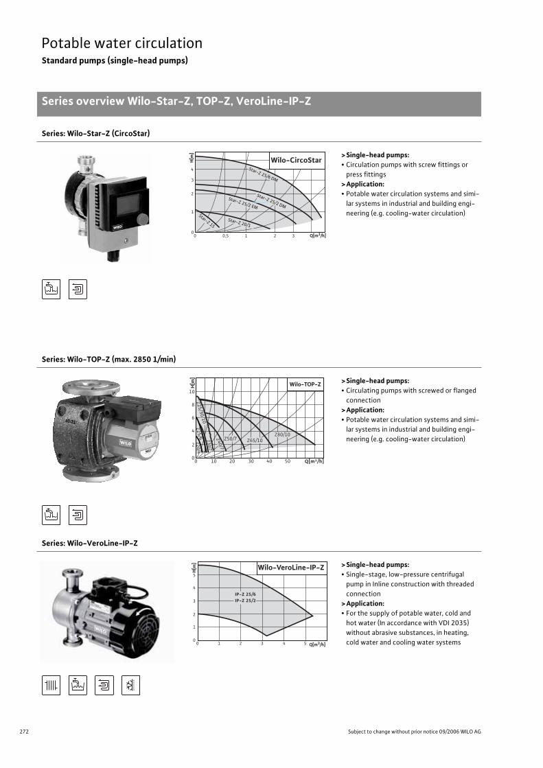
272 Subject to change without prior notice 09/2006 WILO AG
Potable water circulationStandard pumps (single-head pumps)
Series overview Wilo-Star-Z, TOP-Z, VeroLine-IP-Z
Series: Wilo-Star-Z (CircoStar)
>Single-head pumps:• Circulation pumps with screw fittings or
press fittings
>Application:• Potable water circulation systems and simi-
lar systems in industrial and building engi-
neering (e.g. cooling-water circulation)
Series: Wilo-TOP-Z (max. 2850 1/min)
>Single-head pumps:• Circulating pumps with screwed or flanged
connection
>Application:• Potable water circulation systems and simi-
lar systems in industrial and building engi-
neering (e.g. cooling-water circulation)
Series: Wilo-VeroLine-IP-Z
>Single-head pumps:• Single-stage, low-pressure centrifugal
pump in Inline construction with threaded
connection
>Application:• For the supply of potable water, cold and
hot water (In accordance with VDI 2035)
without abrasive substances, in heating,
cold water and cooling water systems
Potable water cir-culationStandard pumps (single-head pumps)Series overview Wilo-Star-Z, TOP-Z, VeroLine-IP-Z
0 0,5 1 2 30
1
2
3
4
Star-Z 20/1
Star-Z 25/2 EM
Star-Z 25/2 DM
Star-Z 25/6 DM
Wilo-CircoStar
Q[m3/h]
H[m
]
Star-Z 15
Wilo-TOP-ZH[m
]
10
8
6
4
2
0Q[m³/h]0 10 20 30 40 50
Z80/10
Z65/10Z50/7Z4
0/7
Z2
5/6
Z2
0/4
Z3
0/7
Z2
5/3
0/1
0
0
1
0 1 2 3 4 5
2
3
4
5Wilo-VeroLine-IP-Z
IP-Z 25/6IP-Z 25/2
Q[m3/h]
H[m
]
273
Potable water circulationStandard pumps (single-head pumps)
Series overview Wilo-Star-Z, TOP-Z, VeroLine-IP-Z
Wilo Catalogue A1 - Circulating pumps in glandless design
Hea
tin
g, A
ir-c
on
dit
ion
ing
, C
oo
ling
Po
tab
le w
ater
cir
cula
tio
nSo
lar
ther
mal
Serv
ice/
Acc
esso
ries
, Sys
tem
sSw
itch
gea
rs a
nd
Co
ntr
ol
Dev
ices
P
um
p M
anag
emen
t S y
stem
s
Series: Wilo-Star-Z (CircoStar)
> Product advantages:• AC pumps with electrical quick connection
• Standard-equipped heat insulation for Star-Z 15...
• Compression connection (Viega system) for
• Star-Z 15 APress and Star-Z 15 TTPress
• Star-Z 15 TT with an integrated timer and thermostat, LCD with symbolic language, red button
technology and automatic detection of the thermal disinfection of the warm potable water
reservoir.
> Additional information: Page:• Planning Guide: . . . . . . . . . . . . . . . . . . 6
• Equipment/Function: . . . . . . . . . . . . . 274
• Technical Data: . . . . . . . . . . . . . . . . . . 278
• Pump Curves: . . . . . . . . . . . . . . . . . . . . 282
• Terminal Diagrams, Motor Data: . . . 284
• Dimensions, Weights: . . . . . . . . . . . . . 285
• Service/Accessories: . . . . . . . . . . . . . . 325
• Switchgears and Control Devices: . . 351
Series: Wilo-TOP-Z (max. 2850 1/min)
> Product advantages:• Manual power adjustment with 3 speed stages.
• With thermal insulation as standard
• Easy installation with combination flange PN 6/PN 10 (for DN 40 - DN 65)
• Cable feed to terminal box possible on both sides (starting with P1 250 W) with integrated
strain-relief device
• Protection class IP 44
> Additional information: Page:• Planning Guide: . . . . . . . . . . . . . . . . . . 6
• Equipment/Function: . . . . . . . . . . . . . 274
• Technical Data: . . . . . . . . . . . . . . . . . . 288
• Pump Curves: . . . . . . . . . . . . . . . . . . . . 290
• Terminal Diagrams, Motor Data: . . . 294
• Dimensions, Weights: . . . . . . . . . . . . . 296
• Service/Accessories: . . . . . . . . . . . . . . 325
• Switchgears and Control Devices: . . 351
• Pump Management Systems
Wilo-Control: . . . . . . . . . . . . . . . . . . . . 421
Series: Wilo-VeroLine-IP-Z
> Product advantages:• High resistance to corrosive media, due to the stainless steel housing and Noryl impeller
• Great versatility due to suitability for water with hardness values up to 28 °d
> Additional information: Page:• Planning Guide: . . . . . . . . . . . . . . . . . . 6
• Equipment/Function: . . . . . . . . . . . . . 274
• Technical Data: . . . . . . . . . . . . . . . . . . 298
• Pump Curves: . . . . . . . . . . . . . . . . . . . . 300
• Terminal Diagrams, Motor Data: . . . 301
• Dimensions, Weights: . . . . . . . . . . . . . 302
• Service/Accessories: . . . . . . . . . . . . . . 325
• Switchgears and Control Devices: . . 351
• Pump Management Systems
Wilo-Control: . . . . . . . . . . . . . . . . . . . . 421

274 Subject to change without prior notice 09/2006 WILO AG
Potable water circulationStandard pumps (single-head pumps)
Equipment/Function Wilo-Star-Z, Wilo-TOP-Z, VeroLine-IP-Z
Wilo-Star-Z(CircoStar)
Wilo-TOP-Z VeroLine-IP-Z
Operating modes
Speed-stage switching •(only Star-Z 25/6)
•–
Manual control mode (n=constant) – – –
p-c for constant differential pressure – – –
p-v for variable differential pressure – – –
p-T for temperature-prompted differential pressure – – –
Manual functions
Setting the operating mode – – –
Setting the differential-pressure setpoint – – –
Setting to “Autopilot” (automatic setback mode) – – –
Setting the pump to ON/OFF – – –
Setting the speed (manual setting mode) – – –
Setting the speed stages 1(3 with Star-Z 25/6)
3 1
Automatic functions
Stepless power adjustment depending on the oper-ating mode
– – –
“Autopilot” automatic setback mode – – –
Timed switching function for programming 3 on or off times
•(only Z 15 TT, Z 15 TTPress)
––
Temperature control to maintain a constant return temperature in potable water circulation systems
•(only Z 15 TT, Z 15 TTPress)
––
Thermal disinfection routine(detection and support of thermal disinfection of the warm potable water reservoir)
•(only Z 15 TT, Z 15 TTPress)
––
Deblocking function – – –
Blocking protection •(only Z 15 TT, Z 15 TTPress)
– –
Soft start – – –
Safety control – – –
Full motor protection with integrated trip electronics–
•(only for 3~pumps
with P2 180W)–
External control functions
Control input “Overriding Off” – – –
Control input “Overriding Min” – – –
Control input “Analogue in 0- 10 V” (remote speed adjustment)
– – –
Control input “Analogue in 0- 10 V” (remote setpoint adjustment)
– – –
• = available, – = not available
Standard pumps (single-head pumps)Equipment/Function Wilo-Star-Z, Wilo-TOP-Z, VeroLine-
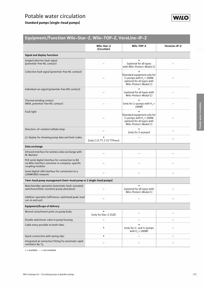
275
Potable water circulationStandard pumps (single-head pumps)
Equipment/Function Wilo-Star-Z, Wilo-TOP-Z, VeroLine-IP-Z
Wilo Catalogue A1 - Circulating pumps in glandless design
Hea
tin
g, A
ir-c
on
dit
ion
ing
, C
oo
ling
Po
tab
le w
ater
cir
cula
tio
nSo
lar
ther
mal
Serv
ice/
Acc
esso
ries
, Sys
tem
sSw
itch
gea
rs a
nd
Co
ntr
ol
Dev
ices
P
um
p M
anag
emen
t S y
stem
s
Signal and display functions
Single/collective fault signal (potential-free NC contact) –
•(optional for all types
with Wilo-Protect-Modul C)–
Collective fault signal (potential-free NC contact)
–
•(Standard equipment only for
3~pumps with P2 180W, optional for all types with
Wilo-Protect-Modul C)
–
Individual run signal (potential-free NO contact)–
•(optional for all types with
Wilo-Protect-Modul C)–
Thermal winding contact (WSK, potential-free NC contact) –
•(only for 1~pumps with P2 =
180W)–
Fault light
–
•(Standard equipment only for
3~pumps with P2 180W, optional for all types with
Wilo-Protect-Modul C)
–
Direction-of-rotation telltale lamp–
•(only for 3~pumps)
–
LC display for showing pump data and fault codes •(only Z 15 TT, Z 15 TTPress)
––
Data exchange
Infrared interface for wireless data exchange with IR-Monitor
– – –
PLR serial digital interface for connection to BA via Wilo interface converter or company-specific coupling modules
– – –
Serial digital LON interface for connection to a LONWORKS network
– – –
Twin-head pump management (twin-head pump or 2 single-head pumps)
Main/standby operation (automatic fault-actuated switchover/time-sensitive pump alteration) –
•(optional for all types with
Wilo-Protect-Modul C)–
Addition operation (efficiency-optimised peak-load cut-in and out)
– – –
Equipment/Scope of delivery
Wrench attachment point on pump body •(only for Star-Z 25/6)
– –
Double switchover valve in pump housing – – –
Cable entry possible on both sides•
•(only for 1~ and 3~pumps
with P2 180W)–
Quick connection with spring clips • – –
Integrated air extraction fitting for automatic rapid ventilator Rp 3/8
– – –
Wilo-Star-Z(CircoStar)
Wilo-TOP-Z VeroLine-IP-Z
• = available, – = not available
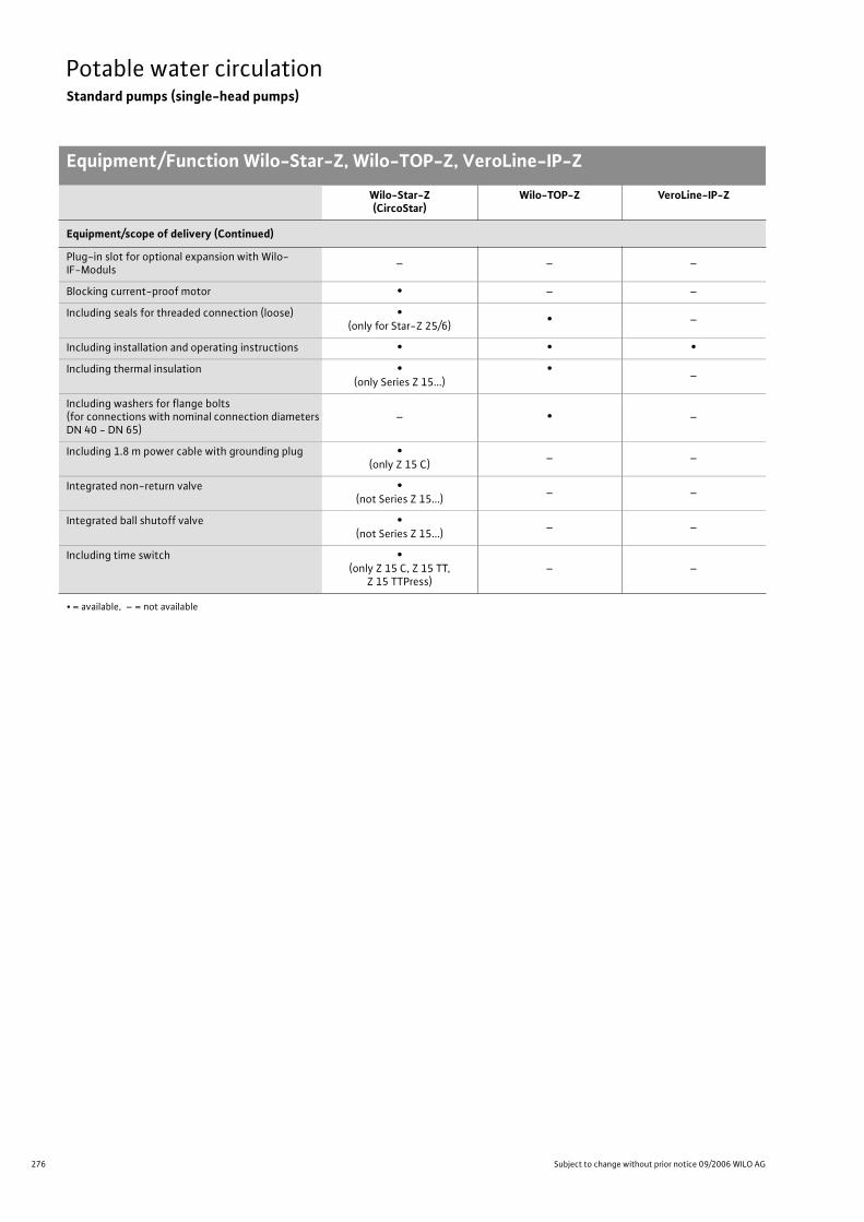
276 Subject to change without prior notice 09/2006 WILO AG
Potable water circulationStandard pumps (single-head pumps)
Equipment/Function Wilo-Star-Z, Wilo-TOP-Z, VeroLine-IP-Z
Equipment/scope of delivery (Continued)
Plug-in slot for optional expansion with Wilo-IF-Moduls
– – –
Blocking current-proof motor • – –
Including seals for threaded connection (loose) •(only for Star-Z 25/6)
• –
Including installation and operating instructions • • •
Including thermal insulation •(only Series Z 15...)
•–
Including washers for flange bolts (for connections with nominal connection diameters DN 40 - DN 65)
– • –
Including 1.8 m power cable with grounding plug •(only Z 15 C)
– –
Integrated non-return valve •(not Series Z 15...)
– –
Integrated ball shutoff valve •(not Series Z 15...)
– –
Including time switch •(only Z 15 C, Z 15 TT,
Z 15 TTPress)– –
Wilo-Star-Z(CircoStar)
Wilo-TOP-Z VeroLine-IP-Z
• = available, – = not available
277
Potable water circulationStandard pumps (single-head pumps)
Wilo Catalogue A1 - Circulating pumps in glandless design
Hea
tin
g, A
ir-c
on
dit
ion
ing
, C
oo
ling
Po
tab
le w
ater
cir
cula
tio
nSo
lar
ther
mal
Serv
ice/
Acc
esso
ries
, Sys
tem
sSw
itch
gea
rs a
nd
Co
ntr
ol
Dev
ices
P
um
p M
anag
emen
t S y
stem
s
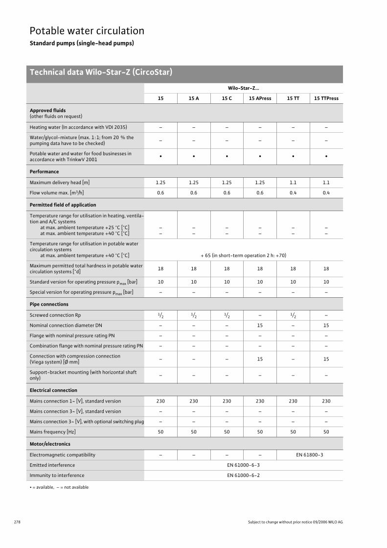
278 Subject to change without prior notice 09/2006 WILO AG
Potable water circulationStandard pumps (single-head pumps)
Technical data Wilo-Star-Z (CircoStar)
Wilo-Star-Z...
15 15 A 15 C 15 APress 15 TT 15 TTPress
Approved fluids(other fluids on request)
Heating water (In accordance with VDI 2035) – – – – – –
Water/glycol-mixture (max. 1:1; from 20 % the pumping data have to be checked)
– – – – – –
Potable water and water for food businesses in accordance with TrinkwV 2001
• • • • • •
Performance
Maximum delivery head [m] 1.25 1.25 1.25 1.25 1.1 1.1
Flow volume max. [m3/h] 0.6 0.6 0.6 0.6 0.4 0.4
Permitted field of application
Temperature range for utilisation in heating, ventila-tion and A/C systems
at max. ambient temperature +25 °C [°C]at max. ambient temperature +40 °C [°C]
––
––
––
––
––
––
Temperature range for utilisation in potable water circulation systems
at max. ambient temperature +40 °C [°C] + 65 (in short-term operation 2 h: +70)
Maximum permitted total hardness in potable water circulation systems [°d]
18 18 18 18 18 18
Standard version for operating pressure pmax [bar] 10 10 10 10 10 10
Special version for operating pressure pmax [bar] – – – – – –
Pipe connections
Screwed connection Rp 1/21/2
1/2 – 1/2 –
Nominal connection diameter DN – – – 15 – 15
Flange with nominal pressure rating PN – – – – – –
Combination flange with nominal pressure rating PN – – – – – –
Connection with compression connection (Viega system) [Ø mm]
– – – 15 – 15
Support-bracket mounting (with horizontal shaft only)
– – – – – –
Electrical connection
Mains connection 1~ [V], standard version 230 230 230 230 230 230
Mains connection 3~ [V], standard version – – – – – –
Mains connection 3~ [V], with optional switching plug – – – – – –
Mains frequency [Hz] 50 50 50 50 50 50
Motor/electronics
Electromagnetic compatibility – – – – EN 61800-3
Emitted interference EN 61000-6-3
Immunity to interference EN 61000-6-2
• = available, – = not available
Technical data Wilo-Star-Z (CircoStar)
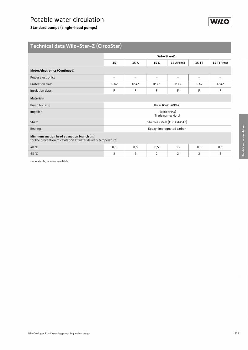
279
Potable water circulationStandard pumps (single-head pumps)
Technical data Wilo-Star-Z (CircoStar)
Wilo Catalogue A1 - Circulating pumps in glandless design
Hea
tin
g, A
ir-c
on
dit
ion
ing
, C
oo
ling
Po
tab
le w
ater
cir
cula
tio
nSo
lar
ther
mal
Serv
ice/
Acc
esso
ries
, Sys
tem
sSw
itch
gea
rs a
nd
Co
ntr
ol
Dev
ices
P
um
p M
anag
emen
t S y
stem
s
Motor/electronics (Continued)
Power electronics – – – – – –
Protection class IP 42 IP 42 IP 42 IP 42 IP 42 IP 42
Insulation class F F F F F F
Materials
Pump housing Brass (CuZn40Pb2)
Impeller Plastic (PPO)Trade name: Noryl
Shaft Stainless steel (X35 CrMo17)
Bearing Epoxy-impregnated carbon
Minimum suction head at suction branch [m]for the prevention of cavitation at water delivery temperature
40 °C 0,5 0,5 0,5 0,5 0,5 0,5
65 °C 2 2 2 2 2 2
Wilo-Star-Z...
15 15 A 15 C 15 APress 15 TT 15 TTPress
• = available, – = not available
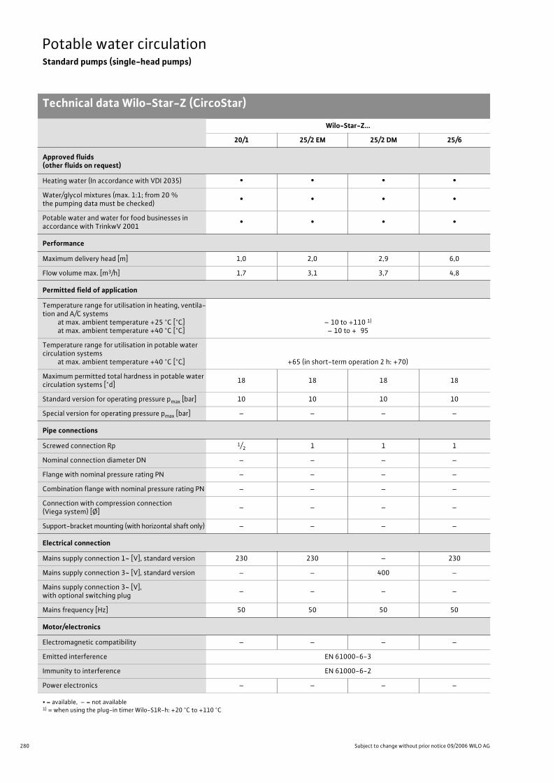
280 Subject to change without prior notice 09/2006 WILO AG
Potable water circulationStandard pumps (single-head pumps)
Technical data Wilo-Star-Z (CircoStar)
Wilo-Star-Z...
20/1 25/2 EM 25/2 DM 25/6
Approved fluids(other fluids on request)
Heating water (In accordance with VDI 2035) • • • •
Water/glycol mixtures (max. 1:1; from 20 % the pumping data must be checked)
• • • •
Potable water and water for food businesses in accordance with TrinkwV 2001
• • • •
Performance
Maximum delivery head [m] 1,0 2,0 2,9 6,0
Flow volume max. [m3/h] 1,7 3,1 3,7 4,8
Permitted field of application
Temperature range for utilisation in heating, ventila-tion and A/C systems
at max. ambient temperature +25 °C [°C]at max. ambient temperature +40 °C [°C]
– 10 to +110 1)
– 10 to + 95
Temperature range for utilisation in potable water circulation systems
at max. ambient temperature +40 °C [°C] +65 (in short-term operation 2 h: +70)
Maximum permitted total hardness in potable water circulation systems [°d]
18 18 18 18
Standard version for operating pressure pmax [bar] 10 10 10 10
Special version for operating pressure pmax [bar] – – – –
Pipe connections
Screwed connection Rp 1/2 1 1 1
Nominal connection diameter DN – – – –
Flange with nominal pressure rating PN – – – –
Combination flange with nominal pressure rating PN – – – –
Connection with compression connection (Viega system) [Ø]
– – – –
Support-bracket mounting (with horizontal shaft only) – – – –
Electrical connection
Mains supply connection 1~ [V], standard version 230 230 – 230
Mains supply connection 3~ [V], standard version – – 400 –
Mains supply connection 3~ [V], with optional switching plug
– – – –
Mains frequency [Hz] 50 50 50 50
Motor/electronics
Electromagnetic compatibility – – – –
Emitted interference EN 61000-6-3
Immunity to interference EN 61000-6-2
Power electronics – – – –
• = available, – = not available1) = when using the plug-in timer Wilo-S1R-h: +20 °C to +110 °C
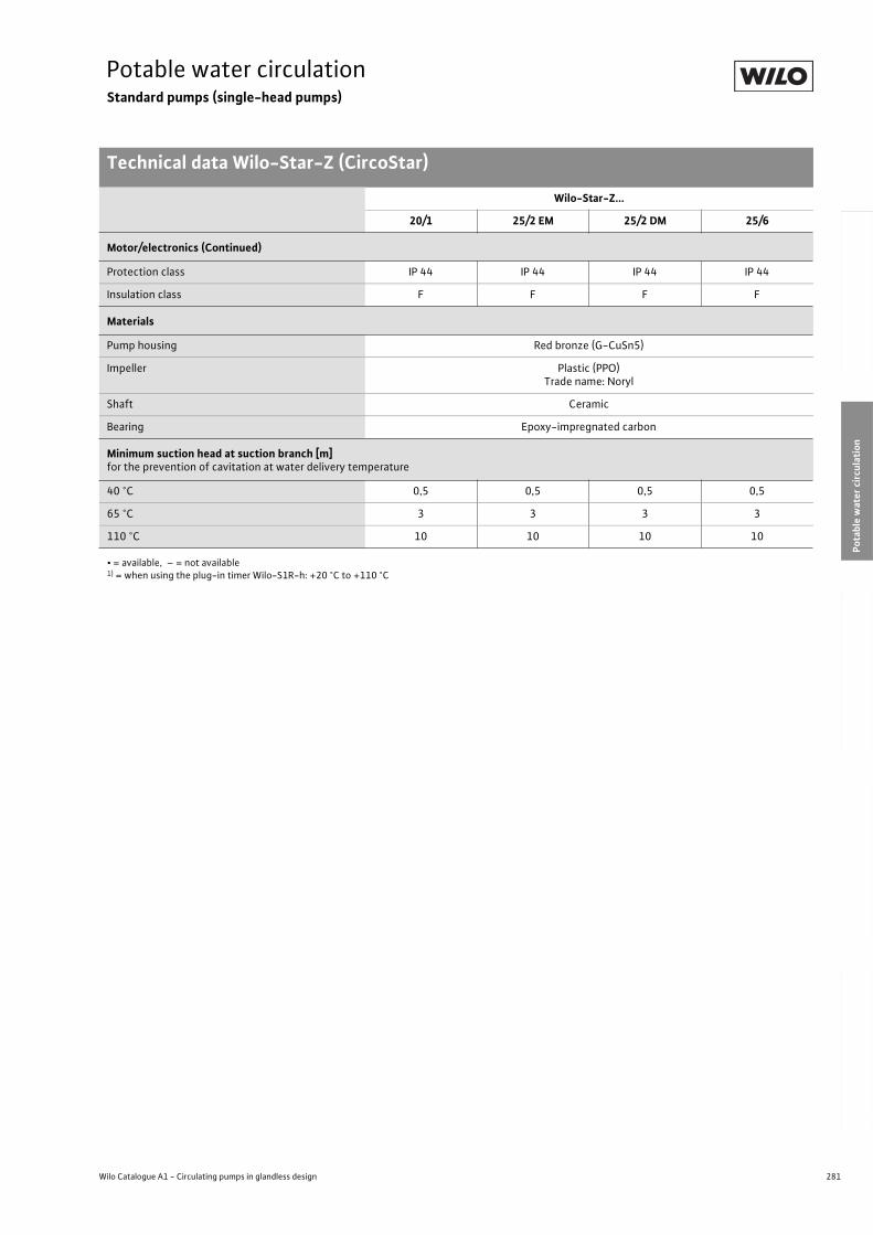
281
Potable water circulationStandard pumps (single-head pumps)
Technical data Wilo-Star-Z (CircoStar)
Wilo Catalogue A1 - Circulating pumps in glandless design
Hea
tin
g, A
ir-c
on
dit
ion
ing
, C
oo
ling
Po
tab
le w
ater
cir
cula
tio
nSo
lar
ther
mal
Serv
ice/
Acc
esso
ries
, Sys
tem
sSw
itch
gea
rs a
nd
Co
ntr
ol
Dev
ices
P
um
p M
anag
emen
t S y
stem
s
Motor/electronics (Continued)
Protection class IP 44 IP 44 IP 44 IP 44
Insulation class F F F F
Materials
Pump housing Red bronze (G-CuSn5)
Impeller Plastic (PPO)Trade name: Noryl
Shaft Ceramic
Bearing Epoxy-impregnated carbon
Minimum suction head at suction branch [m]for the prevention of cavitation at water delivery temperature
40 °C 0,5 0,5 0,5 0,5
65 °C 3 3 3 3
110 °C 10 10 10 10
Wilo-Star-Z...
20/1 25/2 EM 25/2 DM 25/6
• = available, – = not available1) = when using the plug-in timer Wilo-S1R-h: +20 °C to +110 °C
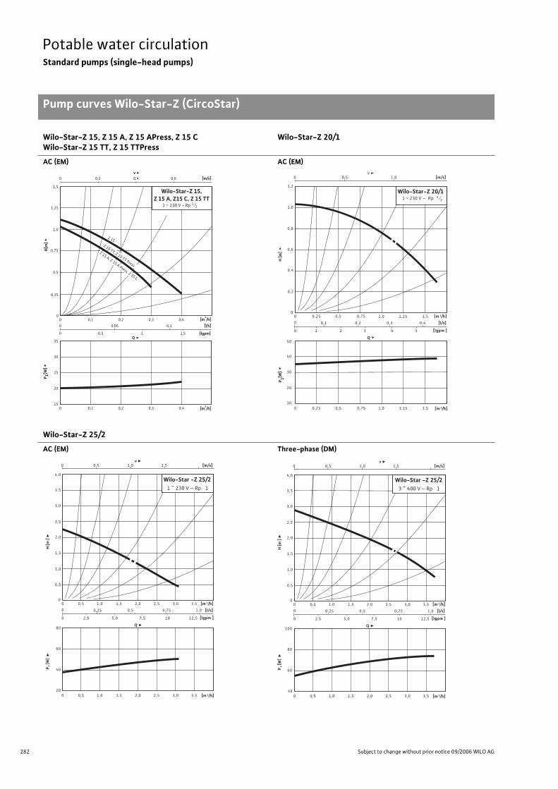
282 Subject to change without prior notice 09/2006 WILO AG
Potable water circulationStandard pumps (single-head pumps)
Pump curves Wilo-Star-Z (CircoStar)
Wilo-Star-Z 15, Z 15 A, Z 15 APress, Z 15 CWilo-Star-Z 15 TT, Z 15 TTPress
Wilo-Star-Z 20/1
AC (EM) AC (EM)
Wilo-Star-Z 25/2
AC (EM) Three-phase (DM)
00
0,5
15
20
25
30
35
0,1 0,2 0,3 0,4
0 0,05
0 0,5 1 1,5
0,1
0 0,2 0,4 0,6
0 0,1 0,2 0,3 0,4
[m/s]
Q[lgpm]
[l/s] [m³/h]
P 1[W
]H
[m]
[m³/h]
0,25
0,75
1,0
1,5
1,25
Wilo-Star-Z 15,Z 15 A, Z15 C, Z 15 TT
Z 15
Z 15 TT, Z 15 TT Press
Z 15 A, Z 15 A Press, Z 15 C
v
1 ~ 230 V - Rp 1⁄2
P 1[W]
Q
H [m
]
0,50
00
0
[m 3/h]
[l/s]
[lgpm ]
[m 3/h]
[m/s]
0,2
v1,0
0,2
10
0,5 1,0 1,5
0,3
20
30
50
0,4
0,6
0,8
1,0
2 3 40
1,2
1
0,1
5
0,4
0
40
Wilo-Star-Z 20/11 ~ 230 V – Rp 1⁄2
0,25 0,75 1,25
0,5 1,0 1,50,25 0,75 1,25
P1 [
W]
�
Q �
H [m
] �
0,50
00
0
[m 3/h]
[l/s]
[lgpm ]
[m 3/h]
0,5
[m/s]
0,5
v �1,0
0,25
1,5 2,0 2,5
0,5
40
60
80
1,0
2,5
3,0
4,0
2,5 5,0 7,5
1,0 3,0 3,5
0,75
10
1,0
12,50
1,5
1,5
2,0
200 0,5 1,5 2,0 2,51,0 3,0 3,5
Wilo-Star -Z 25/21 ~ 230 V – Rp 13,5
P1 [
W]
�
Q �
H [m
] �
0,50
00
0
[m 3/h]
[l/s]
[lgpm ]
[m 3/h]
0,5
[m/s]
0,5
v �1,0
0,25
1,5 2,0 2,5
0,5
60
80
100
1,0
2,5
3,0
4,0
2,5 5,0 7,5
1,0 3,0 3,5
0,75
10
1,0
12,50
1,5
1,5
2,0
3,5
400 0,5 1,5 2,0 2,51,0 3,0 3,5
Wilo-Star -Z 25/23 ~ 400 V – Rp 1
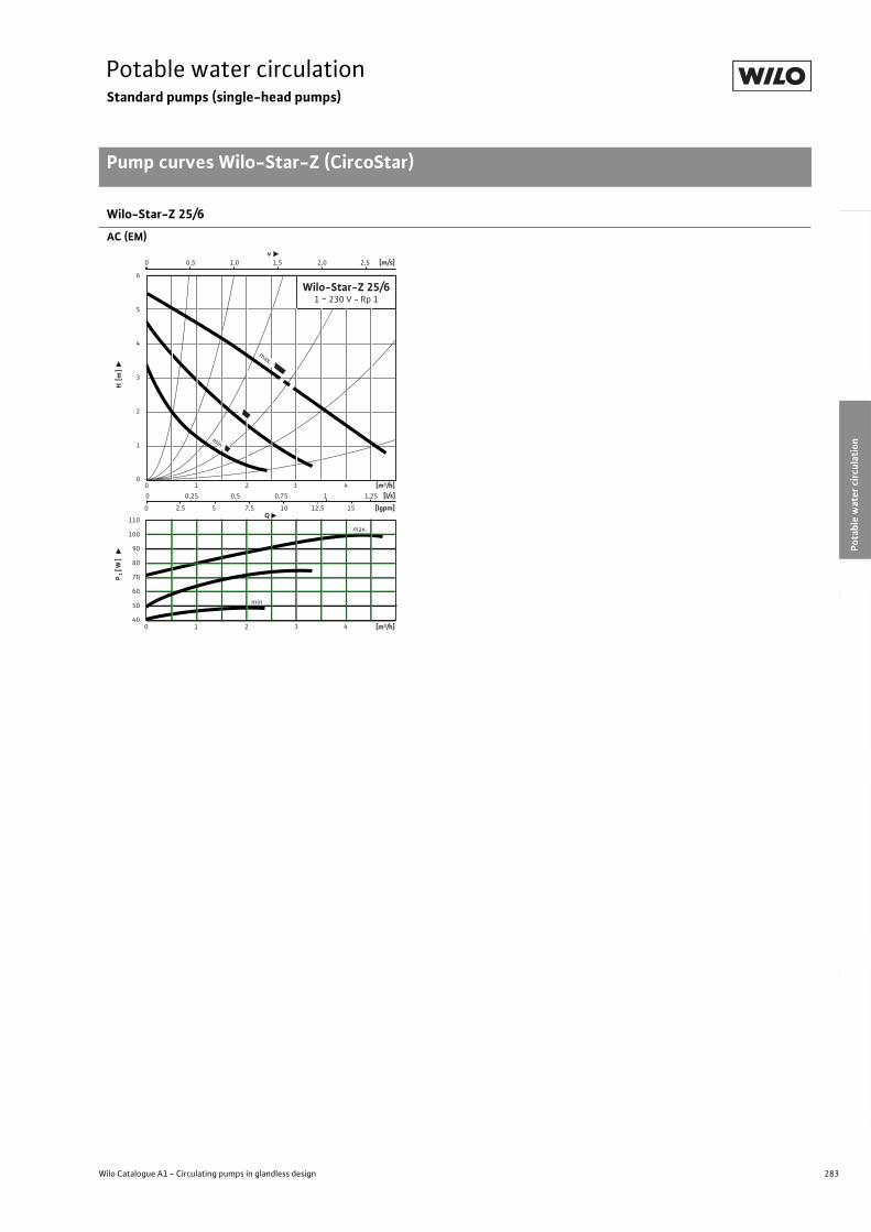
283
Potable water circulationStandard pumps (single-head pumps)
Pump curves Wilo-Star-Z (CircoStar)
Wilo Catalogue A1 - Circulating pumps in glandless design
Hea
tin
g, A
ir-c
on
dit
ion
ing
, C
oo
ling
Po
tab
le w
ater
cir
cula
tio
nSo
lar
ther
mal
Serv
ice/
Acc
esso
ries
, Sys
tem
sSw
itch
gea
rs a
nd
Co
ntr
ol
Dev
ices
P
um
p M
anag
emen
t S y
stem
s
Wilo-Star-Z 25/6
AC (EM)
110
100
90
80
70
60
50
40
0 0,25 0,5 0,75 1 1,25
0 2,5 5 7,5 10 12,5 15
0 0,5 1,0 1,5 2,0 2,5
0 1 2 3 4
v [m/s]
P1 [
W]
H [m
]
Q
[m3/h]
[lgpm]
6
5
4
3
2
1
0
[l/s]
Wilo-Star-Z 25/61 ~ 230 V - Rp 1
[m3/h]0 1 2 3 4
max.
max.
min
min
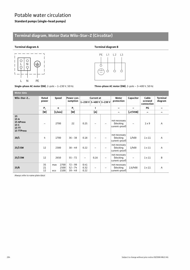
284 Subject to change without prior notice 09/2006 WILO AG
Potable water circulationStandard pumps (single-head pumps)
Terminal diagram, Motor Data Wilo-Star-Z (CircoStar)
Terminal diagram A Terminal diagram B
Single-phase AC motor (EM), 2-pole – 1~230 V, 50 Hz Three-phase AC motor (DM), 2-pole – 3~400 V, 50 Hz
Motor data
Wilo-Star-Z... Rated power
Speed Power con-sumption
Current at Motor protection
Capacitor Cablescrewed
connection
Terminal diagram1~230 V 3~400 V 3~230 V
P2 n P1 I – – PG –
[W] [1/min] [W] [A] – [ F/VDB] – –
1515 A15 APress15 C15 TT15 TTPress
– 2700 22 0.25 – –not necessary
(blocking current-proof)
– 1 x 9 A
20/1 4 1700 36 - 38 0.18 – –not necessary
(blocking current-proof)
1/400 1 x 11 A
25/2 EM 12 2300 38 - 49 0.22 – –not necessary
(blocking current-proof)
1/400 1 x 11 A
25/2 DM 12 2650 55 - 72 – 0,16 –not necessary
(blocking current-proof)
– 1 x 11 B
25/6352112
max 27002500
eco 2100
72 - 9952 - 7439 - 49
0.410.320.22
– –not necessary
(blocking current-proof)
2,6/400 1 x 11 A
Always refer to name plate data!
Terminal diagram, Motor Data Wilo-Star-Z (CircoStar)
L N
L N
PE
L1 L3PE L2
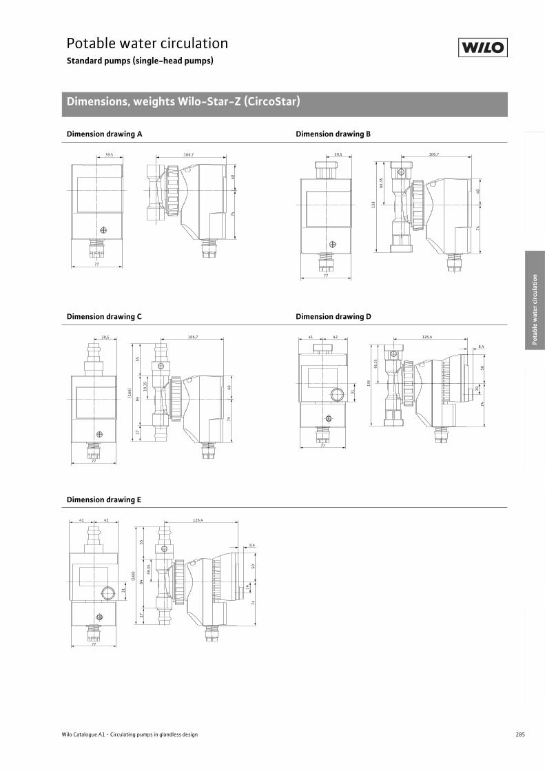
285
Potable water circulationStandard pumps (single-head pumps)
Dimensions, weights Wilo-Star-Z (CircoStar)
Wilo Catalogue A1 - Circulating pumps in glandless design
Hea
tin
g, A
ir-c
on
dit
ion
ing
, C
oo
ling
Po
tab
le w
ater
cir
cula
tio
nSo
lar
ther
mal
Serv
ice/
Acc
esso
ries
, Sys
tem
sSw
itch
gea
rs a
nd
Co
ntr
ol
Dev
ices
P
um
p M
anag
emen
t S y
stem
s
Dimension drawing A Dimension drawing B
Dimension drawing C Dimension drawing D
Dimension drawing E
Dimen-sions, weights Wilo-Star-Z (CircoStar)
106,739,5
77
4074
106,7
66,3
5
138
39,5
77
4074
106,7
39,3
5
5584
27
(166
)
39,5
77
4074
126,4
8,431
42
77
5074
19
41
66,3
5
138
126,4
8,4
39,3
5
5584
31
27
(166
)
42
77
5074
19
41
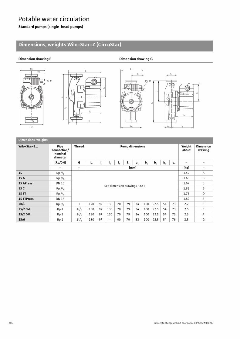
286 Subject to change without prior notice 09/2006 WILO AG
Potable water circulationStandard pumps (single-head pumps)
Dimensions, weights Wilo-Star-Z (CircoStar)
Dimension drawing F Dimension drawing G
Dimensions, Weights
Wilo-Star-Z... Pipe connection/
nominal diameter
Thread Pump dimensions Weight about
Dimension drawing
[Rp/DN] G I0 l1 l2 l3 l4 a1 b1 b2 b3 b4 – –
– – [mm] [kg] –
15 Rp 1/2
See dimension drawings A to E
1.42 A
15 A Rp 1/2 1.63 B
15 APress DN 15 1.67 C
15 C Rp 1/2 1.83 B
15 TT Rp 1/2 1.76 D
15 TTPress DN 15 1.82 E
20/1 Rp 1/2 1 140 97 130 70 79 34 100 92.5 54 73 2.2 F
25/2 EM Rp 1 11/2 180 97 130 70 79 34 100 92.5 54 73 2.5 F
25/2 DM Rp 1 11/2 180 97 130 70 79 34 100 92.5 54 73 2.3 F
25/6 Rp 1 11/2 180 97 – 90 79 33 100 92.5 54 76 2.5 G
b 4
l 0
l1
l4
l 3
G
b2
b1
PG 11
b3
a1
l2G
b4
l1
l4
l 3
l 0
b2 a1
b1
b3
Pg 11

287
Potable water circulationStandard pumps (single-head pumps)
Wilo Catalogue A1 - Circulating pumps in glandless design
Hea
tin
g, A
ir-c
on
dit
ion
ing
, C
oo
ling
Po
tab
le w
ater
cir
cula
tio
nSo
lar
ther
mal
Serv
ice/
Acc
esso
ries
, Sys
tem
sSw
itch
gea
rs a
nd
Co
ntr
ol
Dev
ices
P
um
p M
anag
emen
t S y
stem
s
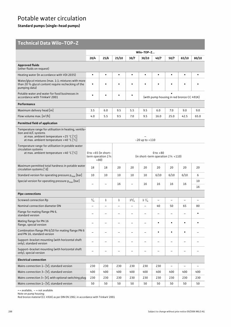
288 Subject to change without prior notice 09/2006 WILO AG
Potable water circulationStandard pumps (single-head pumps)
Technical Data Wilo-TOP-Z
Wilo-TOP-Z...
20/4 25/6 25/10 30/7 30/10 40/7 50/7 65/10 80/10
Approved fluids(other fluids on request)
Heating water (In accordance with VDI 2035) • • • • • • • • •
Water/glycol mixtures (max. 1:1; mixtures with more than 20 % glycol content require rechecking of the pumping data)
• • • • • • • • •
Potable water and water for food businesses in accordance with TrinkwV 2001
• • • • •(with pump housing in red bronze CC 491K)
Performance
Maximum delivery head [m] 3.5 6.0 9.5 5.5 9.5 6.0 7.0 9.0 9.0
Flow volume max. [m3/h] 4.0 5.5 9.5 7.0 9.5 16.0 25.0 42.5 65.0
Permitted field of application
Temperature range for utilisation in heating, ventila-tion and A/C systems
at max. ambient temperature +25 °C [°C]at max. ambient temperature +40 °C [°C]
–-20 up to +110
Temperature range for utilisation in potable water circulation systems
at max. ambient temperature +40 °C [°C] 0 to +65 (in short-term operation 2 h:
+80)
0 to +80(in short-term operation 2 h: +110)
Maximum permitted total hardness in potable water circulation systems [°d]
18 18 20 20 20 20 20 20 20
Standard version for operating pressure pmax [bar] 10 10 10 10 10 6/10 6/10 6/10 6
Special version for operating pressure pmax [bar]– – 16 – 16 16 16 16
10
16
Pipe connections
Screwed connection Rp 3/4 1 1 11/4 1 1/4 – – – –
Nominal connection diameter DN – – – – – 40 50 65 80
Flange for mating flange PN 6, standard version
– – – – – – – – •
Mating flange for PN 16 flange, special version
– – – – – • • • •
Combination flange PN 6/10 for mating flange PN 6 and PN 16, standard version
– – – – – • • • –
Support-bracket mounting (with horizontal shaft only), standard version
– – – – – – – – –
Support-bracket mounting (with horizontal shaft only), special version
– – – – – – – – –
Electrical connection
Mains connection 1~ [V], standard version 230 230 230 230 230 230 – – –
Mains connection 3~ [V], standard version 400 400 400 400 400 400 400 400 400
Mains connection 3~ [V], with optional switching plug 230 230 230 230 230 230 230 230 230
Mains connection 1~ [V], standard version 50 50 50 50 50 50 50 50 50
• = available, – = not availableNote on pump housing:Red bronze material (CC 491K) as per DIN EN 1982, in accordance with TrinkwV 2001
Technical Data Wilo-TOP-Z
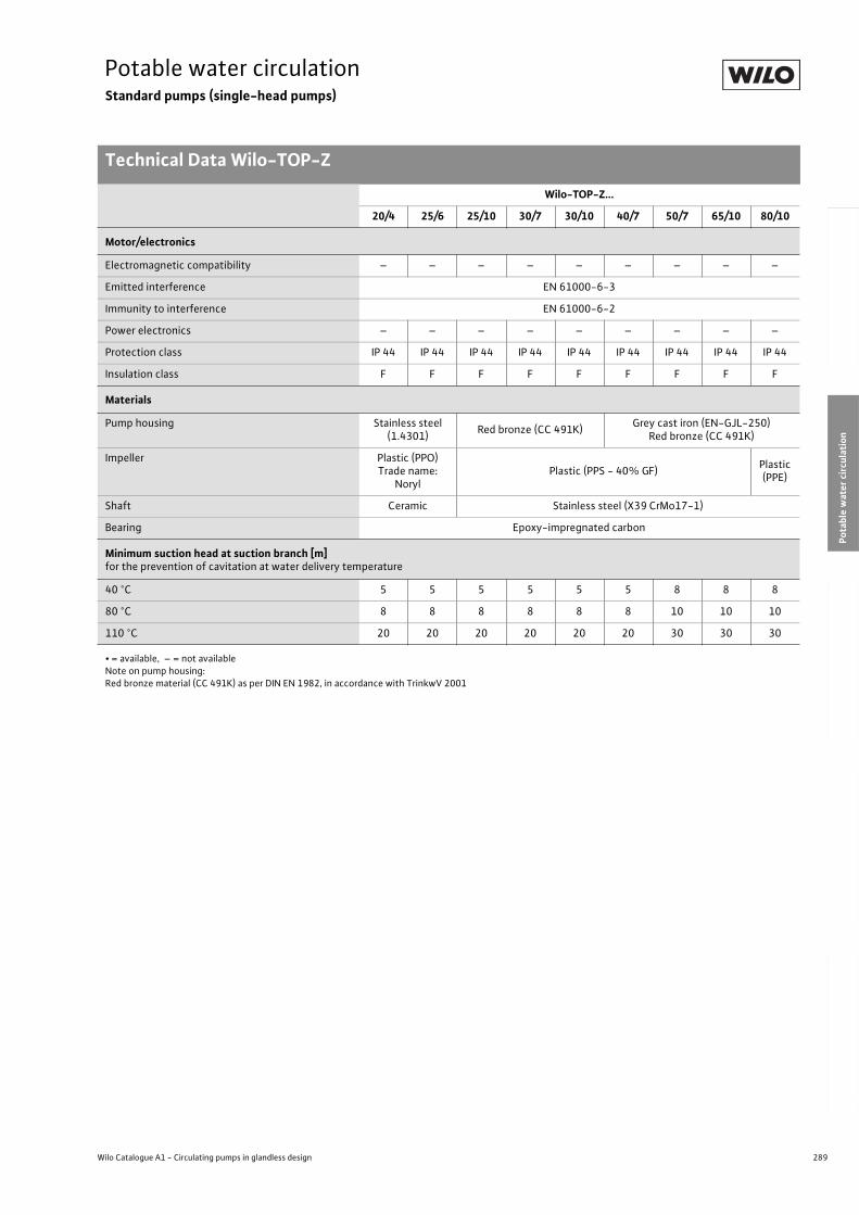
289
Potable water circulationStandard pumps (single-head pumps)
Technical Data Wilo-TOP-Z
Wilo Catalogue A1 - Circulating pumps in glandless design
Hea
tin
g, A
ir-c
on
dit
ion
ing
, C
oo
ling
Po
tab
le w
ater
cir
cula
tio
nSo
lar
ther
mal
Serv
ice/
Acc
esso
ries
, Sys
tem
sSw
itch
gea
rs a
nd
Co
ntr
ol
Dev
ices
P
um
p M
anag
emen
t S y
stem
s
Motor/electronics
Electromagnetic compatibility – – – – – – – – –
Emitted interference EN 61000-6-3
Immunity to interference EN 61000-6-2
Power electronics – – – – – – – – –
Protection class IP 44 IP 44 IP 44 IP 44 IP 44 IP 44 IP 44 IP 44 IP 44
Insulation class F F F F F F F F F
Materials
Pump housing Stainless steel (1.4301)
Red bronze (CC 491K)Grey cast iron (EN-GJL-250)
Red bronze (CC 491K)
Impeller Plastic (PPO)Trade name:
NorylPlastic (PPS - 40% GF)
Plastic(PPE)
Shaft Ceramic Stainless steel (X39 CrMo17-1)
Bearing Epoxy-impregnated carbon
Minimum suction head at suction branch [m]for the prevention of cavitation at water delivery temperature
40 °C 5 5 5 5 5 5 8 8 8
80 °C 8 8 8 8 8 8 10 10 10
110 °C 20 20 20 20 20 20 30 30 30
Wilo-TOP-Z...
20/4 25/6 25/10 30/7 30/10 40/7 50/7 65/10 80/10
• = available, – = not availableNote on pump housing:Red bronze material (CC 491K) as per DIN EN 1982, in accordance with TrinkwV 2001
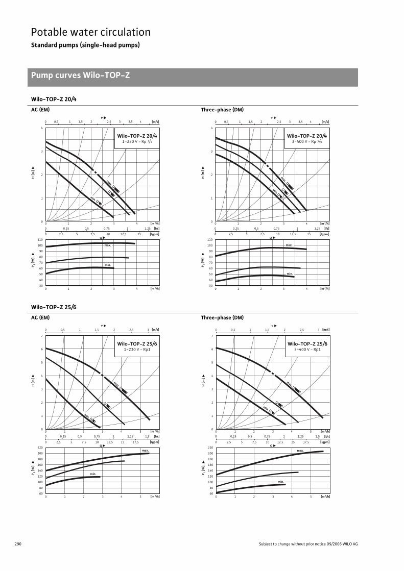
290 Subject to change without prior notice 09/2006 WILO AG
Potable water circulationStandard pumps (single-head pumps)
Pump curves Wilo-TOP-Z
Wilo-TOP-Z 20/4
AC (EM) Three-phase (DM)
Wilo-TOP-Z 25/6
AC (EM) Three-phase (DM)
Pump curves Wilo-TOP-Z
0 1 2 3 4
0 1 2 3 4 [m 3/h]
P1 [
W]
H [m
]
Q
[m 3/h]
110
100
90
80
70
60
50
40
30
4
3
2
1
0
Wilo-TOP-Z 20/41~230 V - Rp 3/4
0 0,25 0,5 0,75 1 1,25
0 2,5 5 7,5 10 12,5 15 [lgpm]
[l/s]
min.
v [m/s]
max.
max. (1 )(2 )min. (3 )
v0 0,5 1 1,5 2 2,5 3 3,5 4
0 0,25 0,5 0,75 1 1,25
[lgpm]
[l/s]0 1 2 3 4
0 1 2 3 4 [m 3/h]
P1 [
W]
H [m
]
Q
[m 3/h]
110
100
90
80
70
60
50
40
30
4
3
2
1
0
Wilo-TOP-Z 20/43~400 V - Rp 3/4
max.
min.
0 0,5 1 1,5 2 2,5 3 3,5 4max. (1 )min. (3 )
(2 )v
[m/s]
0 2,5 5 7,5 10 12,5 15
0 0,25 0,5 0,75 1 1,25 1,5
0 2,5 5 7,5 10 12,5 15 17,5
0 1 2 3 4 5
0 1 2 3 4 5 [m 3/h]
P1 [
W]
H [m
]
Q
[m 3/h]
[lgpm]
220
200
180
160
140
120
100
80
60
7
6
5
4
3
2
1
0
[l/s]
Wilo-TOP-Z 25/61~230 V - Rp1
max. (1 )
min.
0 0,5 1 1,5 2 2,5 3v
[m/s]
min. (3 )
max.
(2 )
0 0,5 1 1,5 2 2,5 3v
[m/s]
0 0,25 0,5 0,75 1 1,25 1,5
0 2,5 5 7,5 10 12,5 15 17,5
0 1 2 3 4 5
0 1 2 3 4 5 [m 3/h]
P1 [
W]
H [m
]
Q
[m 3/h]
[lgpm]
220
200
180
160
140
120
100
80
60
7
6
5
4
3
2
1
0
[l/s]
Wilo-TOP-Z 25/63~400 V - Rp1
max.
min.
min. (3 )
max. (1 )
(2 )
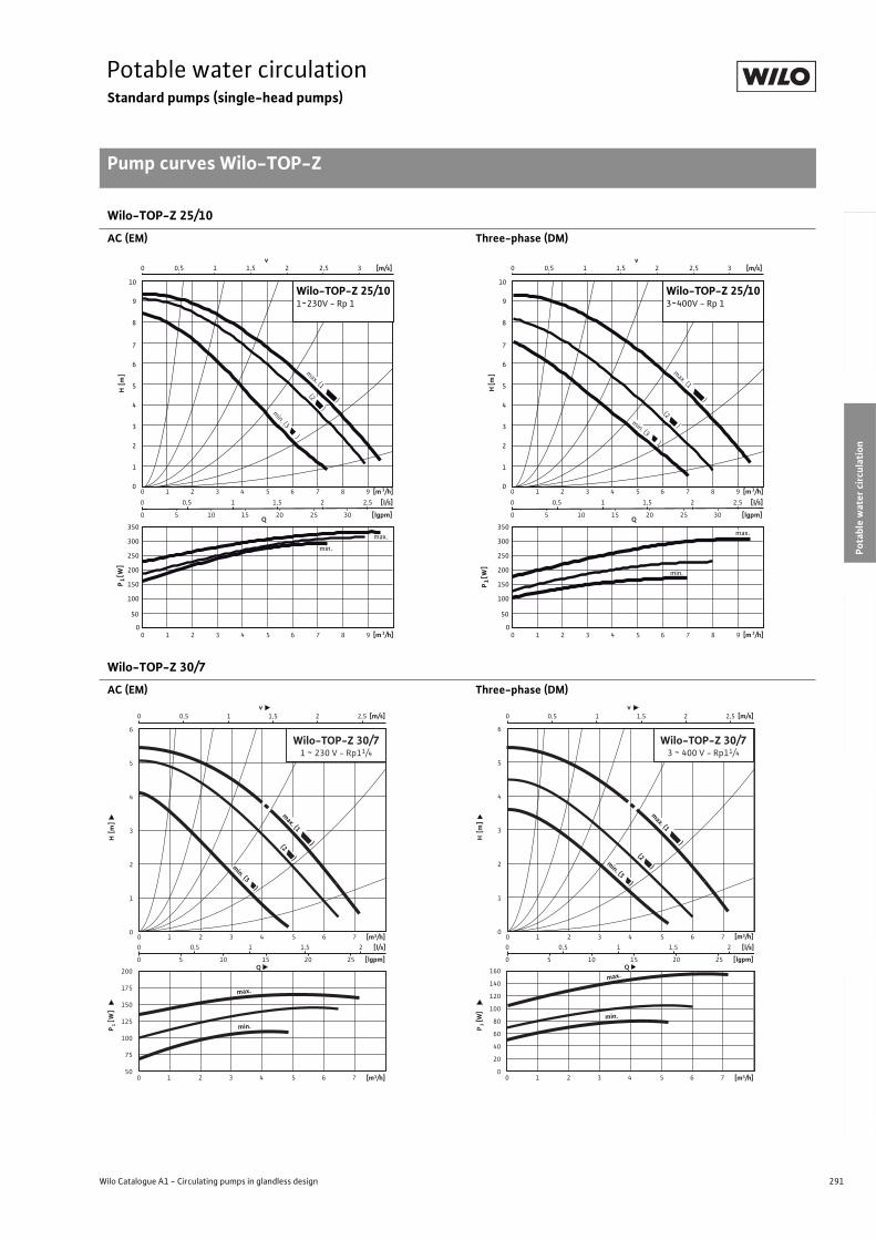
291
Potable water circulationStandard pumps (single-head pumps)
Pump curves Wilo-TOP-Z
Wilo Catalogue A1 - Circulating pumps in glandless design
Hea
tin
g, A
ir-c
on
dit
ion
ing
, C
oo
ling
Po
tab
le w
ater
cir
cula
tio
nSo
lar
ther
mal
Serv
ice/
Acc
esso
ries
, Sys
tem
sSw
itch
gea
rs a
nd
Co
ntr
ol
Dev
ices
P
um
p M
anag
emen
t S y
stem
s
Wilo-TOP-Z 25/10
AC (EM) Three-phase (DM)
Wilo-TOP-Z 30/7
AC (EM) Three-phase (DM)
0 0,5 1 1,5 2 2,5
0 5 10 15 20 25 30
0 1 2 3 4 5 6 7 8 9
0 1 2 3 4 5 6 7 8 9 [m 3/h]
P1 [
W]
H[m
]
Q
[m 3/h]
[lgpm]
[l/s]
max. (1 )
min. (3 )
(2 )
0 0,5 1 1,5 2 2,5 3
v[m/s]
0
1
2
3
4
5
0
50
100
150
200
250
300
350
6
7
8
9
10
max.
min.
Wilo-TOP-Z 25/101~230V - Rp 1
0 0,5 1 1,5 2 2,5
0 5 10 15 20 25 30
0 1 2 3 4 5 6 7 8 9
0 1 2 3 4 5 6 7 8 9 [m 3/h]
P1 [
W]
H[m
]
Q
[m 3/h]
[lgpm]
[l/s]
max. (1 )
min. (3 )
(2 )
0 0,5 1 1,5 2 2,5 3
v[m/s]
0
1
2
3
4
5
0
50
100
150
200
250
300
350
6
7
8
9
10
max.
min.
Wilo-TOP-Z 25/103~400V - Rp 1
200
175
150
125
100
75
50
0 0,5 1 1,5 2
0 5 10 15 20 25
0 0,5 1 1,5 2 2,5
0 1 2 3 4 5 6 7
v [m/s]
P1 [
W]
H [m
]
Q
[m3/h]
[lgpm]
6
5
4
3
2
1
0
[l/s]
(2 )
[m3/h]
max.
min.
0 1 2 3 4 5 6 7
max. (1 )
min. (3 )
Wilo-TOP-Z 30/71 ~ 230 V - Rp11/4
160
140
120
100
80
60
40
20
0
P1 [
W]
H [m
]
Q
[m3/h]
6
5
4
3
2
1
0
(2 )
max.
min.
0 0,5 1 1,5 2
0 5 10 15 20 25
0 0,5 1 1,5 2 2,5
0 1 2 3 4 5 6 7
v [m/s]
[lgpm]
[l/s]
[m3/h]0 1 2 3 4 5 6 7
Wilo-TOP-Z 30/73 ~ 400 V - Rp11/4
max. (1 )
min. (3 )
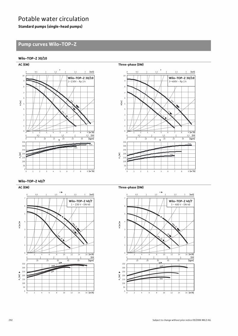
292 Subject to change without prior notice 09/2006 WILO AG
Potable water circulationStandard pumps (single-head pumps)
Pump curves Wilo-TOP-Z
Wilo-TOP-Z 30/10
AC (EM) Three-phase (DM)
Wilo-TOP-Z 40/7
AC (EM) Three-phase (DM)
0 0,5 1 1,5 2 2,5
0 5 10 15 20 25 30
0 1 2 3 4 5 6 7 8 9
0 1 2 3 4 5 6 7 8 9 [m 3/h]
P1 [
W]
H[m
]
Q
[m 3/h]
[lgpm]
[l/s]
max. (1 )
min. (3 )
(2 )
0 0,5 1 1,5 2 2,5 3
v[m/s]
0
1
2
3
4
5
0
50
100
150
200
250
300
350
6
7
8
9
10
max.
min.
Wilo-TOP-Z 30/101~230V - Rp 1¼
0 0,5 1 1,5 2 2,5
0 5 10 15 20 25 30
0 1 2 3 4 5 6 7 8 9
0 1 2 3 4 5 6 7 8 9 [m 3/h]
P1 [
W]
H[m
]
Q
[m 3/h]
[lgpm]
[l/s]
max. (1 )
min. (3 )
(2 )
0 0,5 1 1,5 2 2,5 3
v[m/s]
0
1
2
3
4
5
0
50
100
150
200
250
300
350
6
7
8
9
10
max.
min.
Wilo-TOP-Z 30/103~400V - Rp 1¼
0 1 2 3 4
0 10 20 30 40 50
0 0,5 1 1,5 2 2,5 3
0 2 4 6 8 10 12 14 16
v [m/s]
P1 [
W]
H [m
]
Q
[m3/h]
[lgpm]
7
6
5
4
3
2
1
0
[l/s]
[m3/h]
max.
Wilo-TOP-Z 40/71 ~ 230 V - DN 40
350
300
250
200
150
100
50
0
min.
(2 )min. (3 )
0 2 4 6 8 10 12 14 16
max. (1 )
350
300
250
200
150
100
50
0
P1 [
W]
H [m
]
Q
7
6
5
4
3
2
1
0
(2 )
[m3/h]
max.
min.
0 1 2 3 4
0 10 20 30 40 50
0 0,5 1 1,5 2 2,5 3
0 2 4 6 8 10 12 14 16
v [m/s]
[m3/h]
[lgpm]
[l/s]
0 2 4 6 8 10 12 14 16
Wilo-TOP-Z 40/73 ~ 400 V - DN 40
min. (3 )
max. (1 )
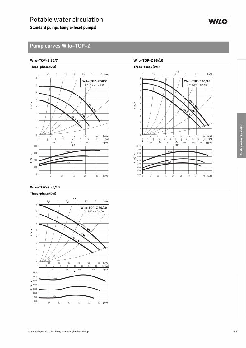
293
Potable water circulationStandard pumps (single-head pumps)
Pump curves Wilo-TOP-Z
Wilo Catalogue A1 - Circulating pumps in glandless design
Hea
tin
g, A
ir-c
on
dit
ion
ing
, C
oo
ling
Po
tab
le w
ater
cir
cula
tio
nSo
lar
ther
mal
Serv
ice/
Acc
esso
ries
, Sys
tem
sSw
itch
gea
rs a
nd
Co
ntr
ol
Dev
ices
P
um
p M
anag
emen
t S y
stem
s
Wilo-TOP-Z 50/7 Wilo-TOP-Z 65/10
Three-phase (DM) Three-phase (DM)
Wilo-TOP-Z 80/10
Three-phase (DM)
800
600
400
200
0
0 1 2 3 4 5 6 7
0 25 50 75
0 0,5 1 1,5 2 2,5 3 3,5
0 5 10 15 20 25
0 5 10 15 20 25
v [m/s]
P1 [
W]
H [m
]
Q
[m3/h]
[lgpm]
8
7
6
5
4
3
2
1
0
[l/s]
(2 )
[m3/h]
max.
min.
Wilo-TOP-Z 50/73 ~ 400 V - DN 50
max. (1 )
min. (3 )
1200
1100
1000
900
800
700
600
500
400
0 1 2 3 4 5 6 7 8 9 10 11
0 20 40 60 80 100 120 140
0 0,5 1 1,5 2 2,5
0 5 10 15 20 25 30 35 40
0 5 10 15 20 25 30 35 40
v [m/s]
P1 [
W]
H [m
]
Q
[m3/h]
[lgpm]
9
8
7
6
5
4
3
2
1
0
[l/s]
(2 )
[m3/h]
max.
min.
Wilo-TOP-Z 65/103 ~ 400 V - DN 65
min. (3 )
max. (1 )
1500
1400
1300
1200
1100
1000
900
800
0 2 4 6 8 10 12 14 16 18
0 50 100 150 200
0 0,5 1 1,5 2 2,5 3
0 10 20 30 40 50 60
0 10 20 30 40 50 60
v [m/s]
P1 [
W]
H [m
]
Q
[m3/h]
[lgpm]
9
8
7
6
5
4
3
2
1
0
[l/s]
(2 )
[m3/h]
max.
min.
Wilo-TOP-Z 80/103 ~ 400 V - DN 80
min. (3 )
max. (1 )
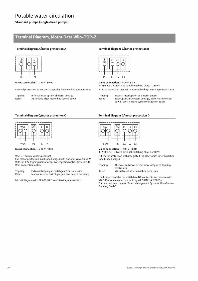
294 Subject to change without prior notice 09/2006 WILO AG
Potable water circulationStandard pumps (single-head pumps)
Terminal Diagram, Motor Data Wilo-TOP-Z
Terminal diagram A/motor protection A Terminal diagram B/motor protection B
Mains connection 1~230 V, 50 Hz Mains connection 3~400 V, 50 Hz3~230 V, 50 Hz (with optional switching plug 3~230 V)
Internal protection against unacceptably high winding temperatures
Tripping: Internal interruption of motor voltageReset: Automatic after motor has cooled down
Internal protection against unacceptably high winding temperatures
Tripping: Internal interruption of a motor phaseReset: Interrupt mains system voltage, allow motor to cool
down, switch mains system voltage on again
Terminal diagram C/motor protection C Terminal diagram D/motor protection D
Mains connection 1~230 V, 50 Hz Mains connection 3~400 V, 50 Hz3~230 V, 50 Hz (with optional switching plug 3~230 V)
WSK = Thermal winding contactFull motor protection in all speed stages with optional Wilo-SK 602/Wilo-SK 622 tripping unit or other switchgears/control devices with WSK connection option
Tripping: External tripping at switchgear/control deviceReset: Manual reset at switchgear/control device necessary
(circuit diagram with SK 602/622, see “Service/Accessories”)
Full motor protection with integrated trip electronics in terminal box for all speed stages
Tripping: All-pole shutdown of motor by integrated tripping electronics
Reset: Manual reset at terminal box necessary
Load capacity of the potential-free NC contact in accordance with VDI 3814 for die collective fault signal (SSM) 1 A, 250 V ~For function, see chapter “Pump Management Systems Wilo-Control, Planning Guide”
Terminal Diagram, Motor Data Wilo-TOP-Z
L NPE
NL
L1 L2PE
L2
L3
L3L1
L NPE
NL
WSK
WSK
L1 L2 L3PE
L1 L2 L3
SSM
SSM
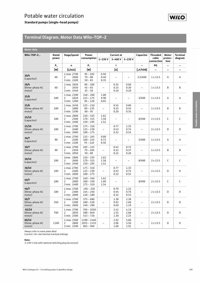
295
Potable water circulationStandard pumps (single-head pumps)
Terminal Diagram, Motor Data Wilo-TOP-Z
Wilo Catalogue A1 - Circulating pumps in glandless design
Hea
tin
g, A
ir-c
on
dit
ion
ing
, C
oo
ling
Po
tab
le w
ater
cir
cula
tio
nSo
lar
ther
mal
Serv
ice/
Acc
esso
ries
, Sys
tem
sSw
itch
gea
rs a
nd
Co
ntr
ol
Dev
ices
P
um
p M
anag
emen
t S y
stem
s
Motor data
Wilo-TOP-Z... Rated power
Stage/speed Power consumption
Current at Capacitor Threaded cable
connection
Motor protec-
tion
Terminal diagram1~230 V 3~400 V 3~230 V
P2 n P1 I – PG – –
[W] [1/min] [W] [A] [ F/VDB] – – –
20/4(capacitor)
601 max. 2790 2 26003 min. 2100
95 - 10570 - 8050 - 65
0.500.400.35
– – 3,5/400 1 x 13.5 A A
20/4(three-phase AC motor)
601 max. 2850 2 26503 min. 2440
80 - 10045 - 6535 - 50
–0.350.150.10
0.600.300.20
– 1 x 13.5 B B
25/6(capacitor)
1001 max. 2390 2 18103 min. 1260
140 - 200115 - 175 85 - 120
1.000.900.65
– – 5/400 1 x 13.5 A A
25/6(three-phase AC motor)
1001 max. 2450 2 18803 min. 1590
125 - 210 80 - 135
60 - 95–
0.450.250.20
0.800.450.35
– 1 x 13.5 B B
25/10(capacitor)
1801 max. 2800 2 25003 min. 2400
210 - 325170 - 315150 - 295
1.621.581.51
– – 8/400 2 x 13.5 C C
25/10(three-phase AC motor)
1801 max. 2700 2 24003 min. 2000
175 - 310125 - 230100 - 175
–0.770.430.32
1.330.740.55
– 2 x 13.5 D D
30/7(capacitor)
901 max. 2700 2 25003 min. 2100
135 - 165100 - 145 70 - 110
0.800.720.56
– – 5/400 1 x 13.5 A A
30/7(three-phase AC motor)
901 max. 2700 2 23503 min. 2050
105 - 155 70 - 105
50 - 80–
0.420.210.15
0.720.370.26
– 1 x 13.5 B B
30/10(capacitor)
1801max. 28002 26003 min. 2400
210 - 335170 - 315150 - 295
1.621.581.51
– – 8/400 2 x 13.5 C C
30/10(three-phase AC motor)
1801 max. 27002 24003 min. 2000
175 - 310125 - 230100 - 175
–0.770.430.32
1.330.740.55
– 2 x 13.5 D D
40/7(capacitor)
1801 max. 2700 2 26003 min. 2400
240 - 340200 - 330175 - 310
1.621.601.54
– – 8/400 2 x 13.5 C C
40/7(three-phase AC motor)
1801 max. 2700 2 23003 min. 2000
195 - 320145 - 240120 - 180
–0.700.440.32
1.220.760.55
– 2 x 13.5 D D
50/7(three-phase AC motor)
3501 max. 2700 2 23003 min. 2000
375 - 680280 - 520240 - 390
–1.380.920.69
2.381.601.19
– 2 x 13.5 D D
65/10(three-phase AC motor)
7001 max. 2700 2 28503 min. 2500
760 - 1050580 - 840515 - 720
–2.421.551.30
4.192.682.25
– 2 x 13.5 D D
80/10(three-phase AC motor)
11001 max. 2500 2 2800 3 min. 2200
1290 - 14401055 - 1155
865 - 940–
2.922.061.68
5.063.562.91
– 2 x 13.5 D D
Always refer to name plate data! Current I: On-site thermal overload settings.
Note:3~230 V only with optional switching plug (accessory)
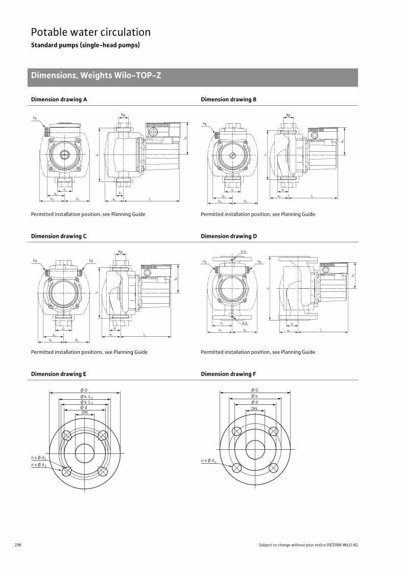
296 Subject to change without prior notice 09/2006 WILO AG
Potable water circulationStandard pumps (single-head pumps)
Dimensions, Weights Wilo-TOP-Z
Dimension drawing A Dimension drawing B
Permitted installation position, see Planning Guide Permitted installation position, see Planning Guide
Dimension drawing C Dimension drawing D
Permitted installation positions, see Planning Guide Permitted installation position, see Planning Guide
Dimension drawing E Dimension drawing F
Dimen-sions, Weights Wilo-TOP-Z
Rp
b1
b2 b2
G
Pg
b 3
a2
a1
l1
l 0
Pg
Rp
b1
b2 b2
G
l 0
b 3
a2
a1
l1
Pg Pg
Rp
b1
b2 b2
G
l 0
b 3
a2
a1
l1
PgPg
l 0
b 3
b1
b2 b2
R 1/8
R 1/8
a1
l1a2
Ø D
n x Ø d
Ø k
DN
L2
Ø k Ø d
L 1
1
n x Ø d 2
n x Ø d
Ø D Ø k
DN
Ø d
L
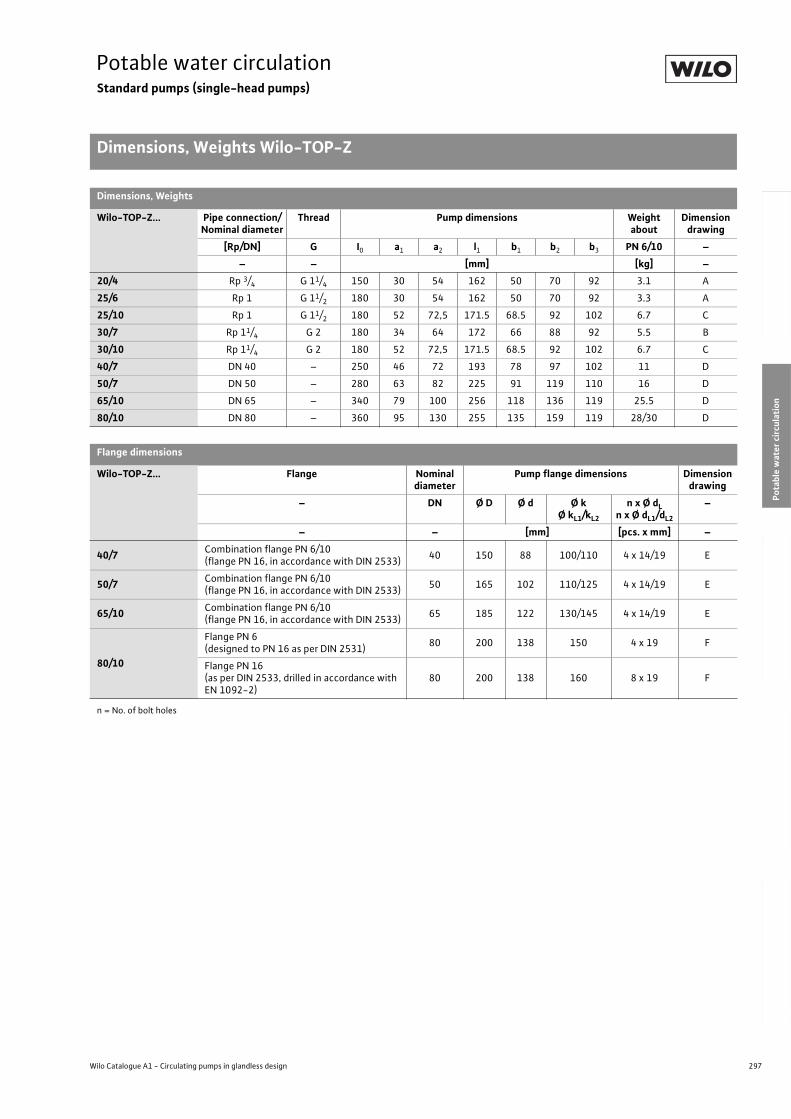
297
Potable water circulationStandard pumps (single-head pumps)
Dimensions, Weights Wilo-TOP-Z
Wilo Catalogue A1 - Circulating pumps in glandless design
Hea
tin
g, A
ir-c
on
dit
ion
ing
, C
oo
ling
Po
tab
le w
ater
cir
cula
tio
nSo
lar
ther
mal
Serv
ice/
Acc
esso
ries
, Sys
tem
sSw
itch
gea
rs a
nd
Co
ntr
ol
Dev
ices
P
um
p M
anag
emen
t S y
stem
s
Dimensions, Weights
Wilo-TOP-Z... Pipe connection/Nominal diameter
Thread Pump dimensions Weight about
Dimension drawing
[Rp/DN] G I0 a1 a2 l1 b1 b2 b3 PN 6/10 –
– – [mm] [kg] –
20/4 Rp 3/4 G 11/4 150 30 54 162 50 70 92 3.1 A
25/6 Rp 1 G 11/2 180 30 54 162 50 70 92 3.3 A
25/10 Rp 1 G 11/2 180 52 72,5 171.5 68.5 92 102 6.7 C
30/7 Rp 11/4 G 2 180 34 64 172 66 88 92 5.5 B
30/10 Rp 11/4 G 2 180 52 72,5 171.5 68.5 92 102 6.7 C
40/7 DN 40 – 250 46 72 193 78 97 102 11 D
50/7 DN 50 – 280 63 82 225 91 119 110 16 D
65/10 DN 65 – 340 79 100 256 118 136 119 25.5 D
80/10 DN 80 – 360 95 130 255 135 159 119 28/30 D
Flange dimensions
Wilo-TOP-Z... Flange Nominal diameter
Pump flange dimensions Dimension drawing
– DN Ø D Ø d Ø kØ kL1/kL2
n x Ø dLn x Ø dL1/dL2
–
– – [mm] [pcs. x mm] –
40/7Combination flange PN 6/10(flange PN 16, in accordance with DIN 2533)
40 150 88 100/110 4 x 14/19 E
50/7Combination flange PN 6/10(flange PN 16, in accordance with DIN 2533)
50 165 102 110/125 4 x 14/19 E
65/10Combination flange PN 6/10(flange PN 16, in accordance with DIN 2533)
65 185 122 130/145 4 x 14/19 E
80/10
Flange PN 6(designed to PN 16 as per DIN 2531)
80 200 138 150 4 x 19 F
Flange PN 16(as per DIN 2533, drilled in accordance with EN 1092-2)
80 200 138 160 8 x 19 F
n = No. of bolt holes
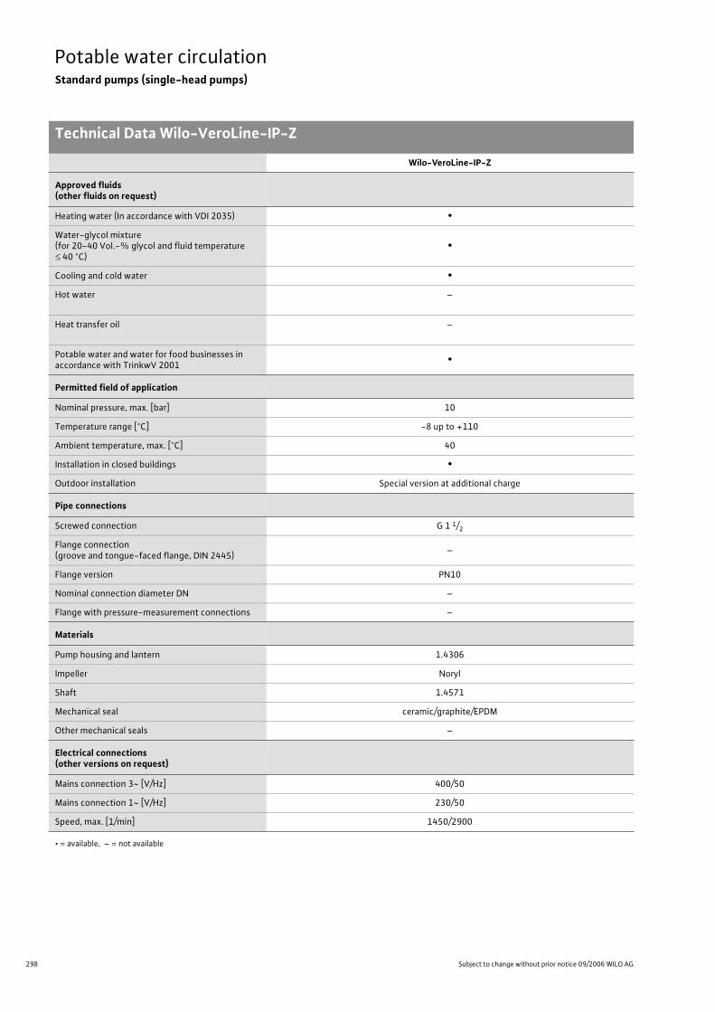
298 Subject to change without prior notice 09/2006 WILO AG
Potable water circulationStandard pumps (single-head pumps)
Technical Data Wilo-VeroLine-IP-Z
Wilo-VeroLine-IP-Z
Approved fluids(other fluids on request)
Heating water (In accordance with VDI 2035) •
Water-glycol mixture(for 20-40 Vol.-% glycol and fluid temperature
40 °C)•
Cooling and cold water •
Hot water –
Heat transfer oil –
Potable water and water for food businesses in accordance with TrinkwV 2001
•
Permitted field of application
Nominal pressure, max. [bar] 10
Temperature range [°C] -8 up to +110
Ambient temperature, max. [°C] 40
Installation in closed buildings •
Outdoor installation Special version at additional charge
Pipe connections
Screwed connection G 1 1/2
Flange connection(groove and tongue-faced flange, DIN 2445)
–
Flange version PN10
Nominal connection diameter DN –
Flange with pressure-measurement connections –
Materials
Pump housing and lantern 1.4306
Impeller Noryl
Shaft 1.4571
Mechanical seal ceramic/graphite/EPDM
Other mechanical seals –
Electrical connections (other versions on request)
Mains connection 3~ [V/Hz] 400/50
Mains connection 1~ [V/Hz] 230/50
Speed, max. [1/min] 1450/2900
• = available, – = not available
Technical Data Wilo-VeroLine-IP-Z
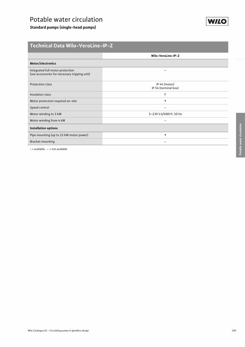
299
Potable water circulationStandard pumps (single-head pumps)
Technical Data Wilo-VeroLine-IP-Z
Wilo Catalogue A1 - Circulating pumps in glandless design
Hea
tin
g, A
ir-c
on
dit
ion
ing
, C
oo
ling
Po
tab
le w
ater
cir
cula
tio
nSo
lar
ther
mal
Serv
ice/
Acc
esso
ries
, Sys
tem
sSw
itch
gea
rs a
nd
Co
ntr
ol
Dev
ices
P
um
p M
anag
emen
t S y
stem
s
Motor/electronics
Integrated full motor protection(see accessories for necessary tripping unit)
–
Protection class IP 44 (motor)IP 54 (terminal box)
Insulation class F
Motor protection required on-site •
Speed control –
Motor winding to 3 kW 3~230 V /400VY, 50 Hz
Motor winding from 4 kW –
Installation options
Pipe mounting (up to 15 kW motor power) •
Bracket mounting –
• = available, – = not available
Wilo-VeroLine-IP-Z
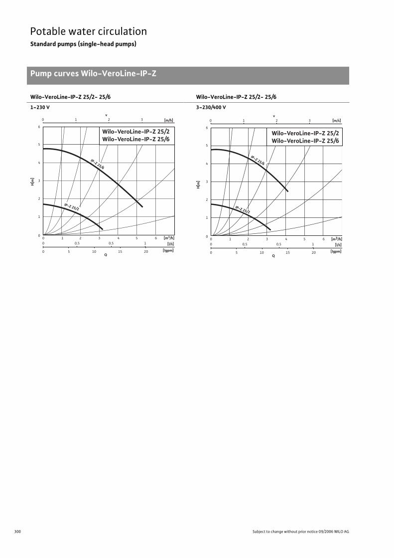
300 Subject to change without prior notice 09/2006 WILO AG
Potable water circulationStandard pumps (single-head pumps)
Pump curves Wilo-VeroLine-IP-Z
Wilo-VeroLine-IP-Z 25/2- 25/6
1~230 V
Wilo-VeroLine-IP-Z 25/2- 25/6
3~230/400 V
Pump curves Wilo-VeroLine-IP-Z
0 1 2 3 v
Q [lgpm]
[l/s]
0
0 0
0,5 1 2 3 4 5 6
5 10 15 20
0,5 1
0
2
1
3
4
5
6
H[m
]
[m/h]
[m3/h]
Wilo-VeroLine-IP-Z 25/2Wilo-VeroLine-IP-Z 25/6
IP-Z 25/2
IP-Z 25/6
0 1 2 3 v
[m/s]
[m3/h]
Q [lgpm]
[l/s]
0
0 0
0,5 1 2 3 4 5 6
5 10 15 20
0,5 1
0
2
1
3
4
5
6
H[m
]
Wilo-VeroLine-IP-Z 25/2 Wilo-VeroLine-IP-Z 25/6
IP-Z 25/2
IP-Z 25/6
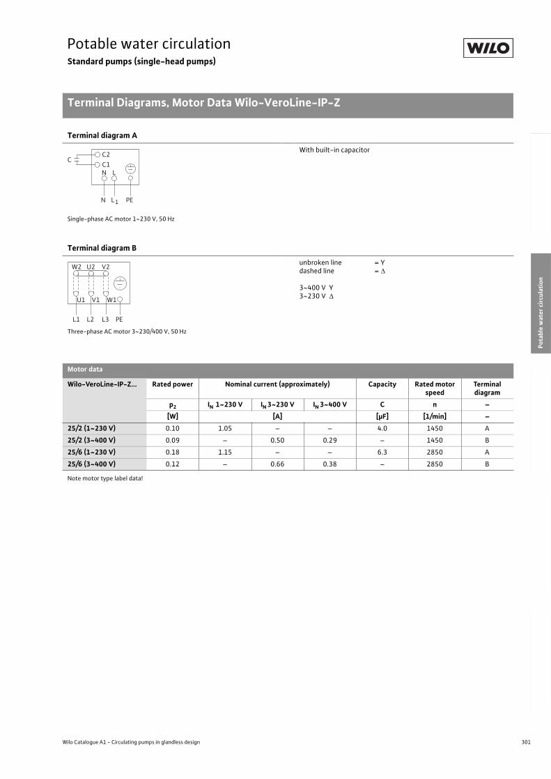
301
Potable water circulationStandard pumps (single-head pumps)
Terminal Diagrams, Motor Data Wilo-VeroLine-IP-Z
Wilo Catalogue A1 - Circulating pumps in glandless design
Hea
tin
g, A
ir-c
on
dit
ion
ing
, C
oo
ling
Po
tab
le w
ater
cir
cula
tio
nSo
lar
ther
mal
Serv
ice/
Acc
esso
ries
, Sys
tem
sSw
itch
gea
rs a
nd
Co
ntr
ol
Dev
ices
P
um
p M
anag
emen
t S y
stem
s
Terminal diagram A
Single-phase AC motor 1~230 V, 50 Hz
With built-in capacitor
Terminal diagram B
Three-phase AC motor 3~230/400 V, 50 Hz
unbroken line = Ydashed line =
3~400 V Y3~230 V
Motor data
Wilo-VeroLine-IP-Z... Rated power Nominal current (approximately) Capacity Rated motor speed
Terminal diagram
p2 IN 1~230 V IN 3~230 V IN 3~400 V C n –
[W] [A] [µF] [1/min] –
25/2 (1~230 V) 0.10 1.05 – – 4.0 1450 A
25/2 (3~400 V) 0.09 – 0.50 0.29 – 1450 B
25/6 (1~230 V) 0.18 1.15 – – 6.3 2850 A
25/6 (3~400 V) 0.12 – 0.66 0.38 – 2850 B
Note motor type label data!
Terminal Diagrams, Motor Data Wilo-VeroLine-IP-Z
L
L1
N
N PE
C1C2
C
L1 L2 L3 PE
W2 U2 V2
U1 V1 W1
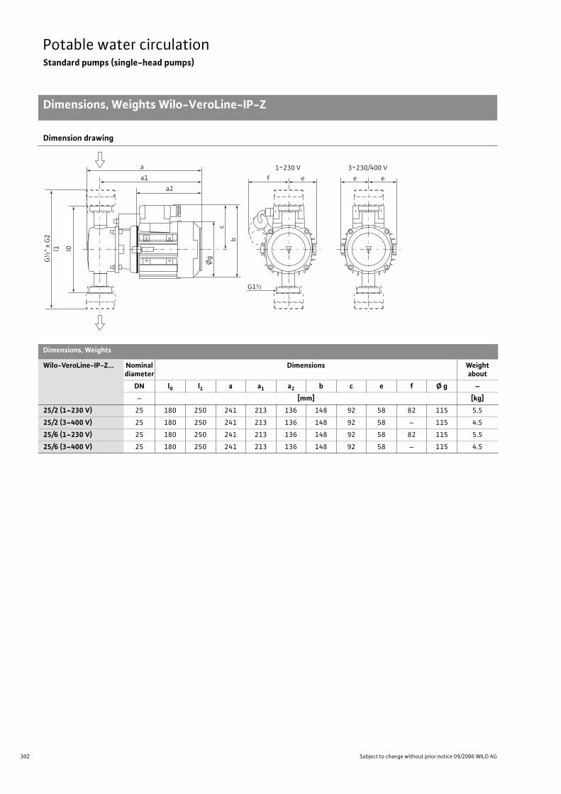
302 Subject to change without prior notice 09/2006 WILO AG
Potable water circulationStandard pumps (single-head pumps)
Dimensions, Weights Wilo-VeroLine-IP-Z
Dimension drawing
Dimensions, Weights
Wilo-VeroLine-IP-Z... Nominal diameter
Dimensions Weightabout
DN l0 l1 a a1 a2 b c e f Ø g –
– [mm] [kg]
25/2 (1~230 V) 25 180 250 241 213 136 148 92 58 82 115 5.5
25/2 (3~400 V) 25 180 250 241 213 136 148 92 58 – 115 4.5
25/6 (1~230 V) 25 180 250 241 213 136 148 92 58 82 115 5.5
25/6 (3~400 V) 25 180 250 241 213 136 148 92 58 – 115 4.5
Dimen-sions, Weights Wilo-VeroLine-IP-Z
a
G1½
f
1~230 V
e e
3~230/400 V
e
Øg
c
b
G½
" x
G2
a1
a2
l0l1
303
Solar thermalContents
Wilo Catalogue A1 - Circulating pumps in glandless design
Hea
tin
g, A
ir-c
on
dit
ion
ing
, C
oo
ling
Po
tab
le w
ater
cir
cula
tio
nSo
lar
ther
mal
Serv
ice/
Acc
esso
ries
, Sys
tem
sSw
itch
gea
rs a
nd
Co
ntr
ol
Dev
ices
P
um
p M
anag
emen
t S y
stem
s
Solar thermal
High-Efficiency Pumps Wilo-Stratos ECO-ST 304
Series overview 304
Wilo-Stratos ECO-ST
Equipment/Function 306
Technical Data 308
Pump Curves 310
Terminal diagram, motor data 311
Dimensions, Weights 312
Standard Pumps Wilo-Star-ST (SolarStar) 314
Series overview 314
Wilo-Star-ST (SolarStar)
Equipment/Function 316
Technical Data 318
Pump Curves 320
Terminal Diagrams, Motor Data 322
Dimensions, Weights 323
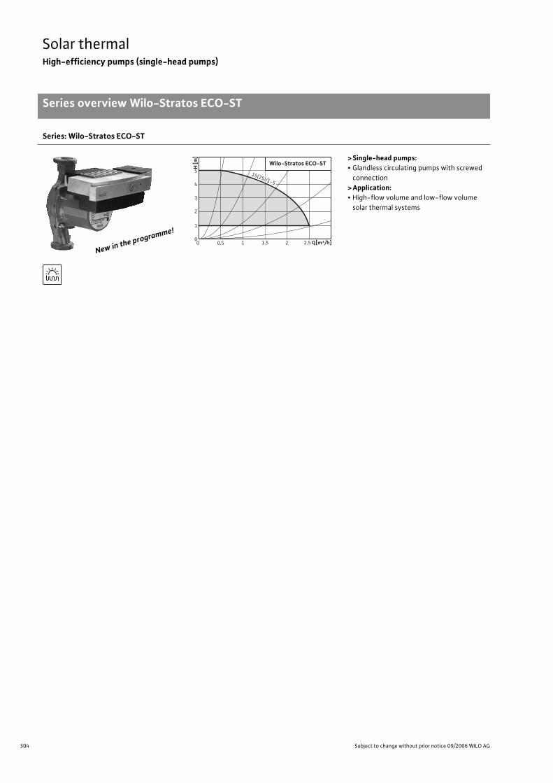
304 Subject to change without prior notice 09/2006 WILO AG
Solar thermalHigh-efficiency pumps (single-head pumps)
Series overview Wilo-Stratos ECO-ST
Series: Wilo-Stratos ECO-ST
>Single-head pumps:• Glandless circulating pumps with screwed
connection
>Application:• High-flow volume and low-flow volume
solar thermal systems
Newin the
programm
e!
H[m
]
5
4
3
2
1
0 Q[m³/h]1,5 1 2,5 2 0 0,5
15(25)/1-5
Wilo-Stratos ECO-ST
305
Solar thermalHigh-efficiency pumps (single-head pumps)
Series overview Wilo-Stratos ECO-ST
Wilo Catalogue A1 - Circulating pumps in glandless design
Hea
tin
g, A
ir-c
on
dit
ion
ing
, C
oo
ling
Po
tab
le w
ater
cir
cula
tio
nSo
lar
ther
mal
Serv
ice/
Acc
esso
ries
, Sys
tem
sSw
itch
gea
rs a
nd
Co
ntr
ol
Dev
ices
P
um
p M
anag
emen
t S y
stem
s
Series: Wilo-Stratos ECO-ST
> Product advantages:• Pump housing with wrench attachment point
• Pump housing with cataphoretic (KTL) painting for the prevention of corrosion from conden-
sation formation
• Minimum electrical power consumption: only 5.8 W
• BA linkup For linkage to external monitoring units
(e.g. building automation BA or DDC installations)
> Additional information: Page:• Planning Guide: . . . . . . . . . . . . . . . . . . 6/29
• Equipment/Function: . . . . . . . . . . . . . 306
• Technical Data: . . . . . . . . . . . . . . . . . . 308
• Pump Curves: . . . . . . . . . . . . . . . . . . . . 310
• Terminal Diagrams, Motor Data: . . . 311
• Dimensions, Weights: . . . . . . . . . . . . . 312
• Service/Accessories: . . . . . . . . . . . . . . 325
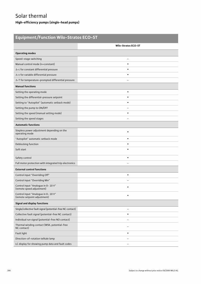
306 Subject to change without prior notice 09/2006 WILO AG
Solar thermalHigh-efficiency pumps (single-head pumps)
Equipment/Function Wilo-Stratos ECO-ST
Wilo-Stratos ECO-ST
Operating modes
Speed-stage switching –
Manual control mode (n=constant) •
-c for constant differential pressure •
-v for variable differential pressure •
-T for temperature-prompted differential pressure –
Manual functions
Setting the operating mode •
Setting the differential-pressure setpoint •
Setting to “Autopilot” (automatic setback mode) •
Setting the pump to ON/OFF –
Setting the speed (manual setting mode) •
Setting the speed stages –
Automatic functions
Stepless power adjustment depending on the operating mode
•
“Autopilot” automatic setback mode •
Deblocking function •
Soft start •
Safety control •
Full motor protection with integrated trip electronics –
External control functions
Control input “Overriding Off” •
Control input “Overriding Min” –
Control input “Analogue in 0- 10 V” (remote speed adjustment)
•
Control input “Analogue in 0- 10 V” (remote setpoint adjustment)
•
Signal and display functions
Single/collective fault signal (potential-free NC contact) –
Collective fault signal (potential-free NC contact) •
Individual run signal (potential-free NO contact) –
Thermal winding contact (WSK, potential-free NC contact)
–
Fault light •
Direction-of-rotation telltale lamp –
LC display for showing pump data and fault codes –
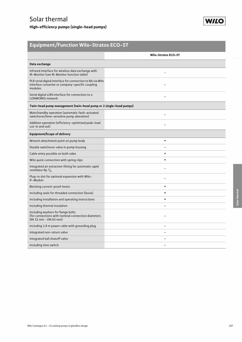
307
Solar thermalHigh-efficiency pumps (single-head pumps)
Equipment/Function Wilo-Stratos ECO-ST
Wilo Catalogue A1 - Circulating pumps in glandless design
Hea
tin
g, A
ir-c
on
dit
ion
ing
, C
oo
ling
Po
tab
le w
ater
cir
cula
tio
nSo
lar
ther
mal
Serv
ice/
Acc
esso
ries
, Sys
tem
sSw
itch
gea
rs a
nd
Co
ntr
ol
Dev
ices
P
um
p M
anag
emen
t S y
stem
s
Data exchange
Infrared interface for wireless data exchange with IR-Monitor (see IR-Monitor function table)
–
PLR serial digital interface for connection to BA via Wilo interface converter or company-specific coupling modules
–
Serial digital LON interface for connection to a LONWORKS network
–
Twin-head pump management (twin-head pump or 2 single-head pumps)
Main/standby operation (automatic fault-actuated switchover/time-sensitive pump alteration)
–
Addition operation (efficiency-optimised peak-load cut-in and out)
–
Equipment/Scope of delivery
Wrench attachment point on pump body •
Double switchover valve in pump housing –
Cable entry possible on both sides •
Wilo quick connection with spring clips •
Integrated air extraction fitting for automatic rapid ventilator Rp 3/8
–
Plug-in slot for optional expansion with Wilo-IF-Moduls
–
Blocking current-proof motor •
Including seals for threaded connection (loose) •
Including installation and operating instructions •
Including thermal insulation –
Including washers for flange bolts (for connections with nominal connection diameters DN 32 mm - DN 65 mm)
–
Including 1.8 m power cable with grounding plug –
Integrated non-return valve –
Integrated ball shutoff valve –
Including time switch –
Wilo-Stratos ECO-ST
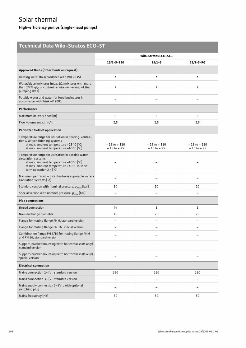
308 Subject to change without prior notice 09/2006 WILO AG
Solar thermalHigh-efficiency pumps (single-head pumps)
Technical Data Wilo-Stratos ECO-ST
Wilo-Stratos ECO-ST...
15/1-5-130 25/1-5 25/1-5-RG
Approved fluids (other fluids on request)
Heating water (In accordance with VDI 2035) • • •
Water/glycol mixtures (max. 1:1; mixtures with more than 20 % glycol content require rechecking of the pumping data)
• • •
Potable water and water for food businesses in accordance with TrinkwV 2001
– – –
Performance
Maximum delivery head [m] 5 5 5
Flow volume max. [m3/h] 2,5 2,5 2,5
Permitted field of application
Temperature range for utilisation in heating, ventila-tion & air conditioning systems
at max. ambient temperature +25 °C [°C]at max. ambient temperature +40 °C [°C]
+ 15 to + 110+ 15 to + 95
+ 15 to + 110+ 15 to + 95
+ 15 to + 110+ 15 to + 95
Temperature range for utilisation in potable water circulation systems
at max. ambient temperature +40 °C [°C]at max. ambient temperature +40 °C in short-term operation 2 h [°C]
–
–
–
–
–
–
Maximum permissible total hardness in potable water- circulation systems [°d]
– – –
Standard version with nominal pressure, p max [bar] 10 10 10
Special version with nominal pressure, pmax [bar] – – –
Pipe connections
thread connection ½ 1 1
Nominal flange diameter 15 25 25
Flange for mating flange PN 6, standard version – – –
Flange for mating flange PN 16, special version – – –
Combination flange PN 6/10 for mating flange PN 6 and PN 16, standard version
– – –
Support-bracket mounting (with horizontal shaft only), standard version
– – –
Support-bracket mounting (with horizontal shaft only), special version
– – –
Electrical connection
Mains connection 1~ [V], standard version 230 230 230
Mains connection 3~ [V], standard version – – –
Mains supply connection 3~ [V] , with optional switching plug
– – –
Mains frequency [Hz] 50 50 50
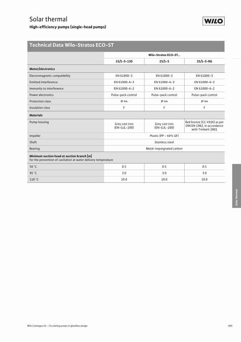
309
Solar thermalHigh-efficiency pumps (single-head pumps)
Technical Data Wilo-Stratos ECO-ST
Wilo Catalogue A1 - Circulating pumps in glandless design
Hea
tin
g, A
ir-c
on
dit
ion
ing
, C
oo
ling
Po
tab
le w
ater
cir
cula
tio
nSo
lar
ther
mal
Serv
ice/
Acc
esso
ries
, Sys
tem
sSw
itch
gea
rs a
nd
Co
ntr
ol
Dev
ices
P
um
p M
anag
emen
t S y
stem
s
Motor/electronics
Electromagnetic compatibility EN 61800-3 EN 61800-3 EN 61800-3
Emitted interference EN 61000-6-3 EN 61000-6-3 EN 61000-6-3
Immunity to interference EN 61000-6-2 EN 61000-6-2 EN 61000-6-2
Power electronics Pulse-pack control Pulse-pack control Pulse-pack control
Protection class IP 44 IP 44 IP 44
Insulation class F F F
Materials
Pump housingGrey cast iron (EN-GJL-200)
Grey cast iron (EN-GJL-200)
Red bronze (CC 491K) as per DIN EN 1982, in accordance
with TrinkwV 2001
Impeller Plastic (PP - 40% GF)
Shaft Stainless steel
Bearing Metal-impregnated carbon
Minimum suction head at suction branch [m] for the prevention of cavitation at water delivery temperature
50 °C 0.5 0.5 0.5
95 °C 3.0 3.0 3.0
110 °C 10.0 10.0 10.0
Wilo-Stratos ECO-ST...
15/1-5-130 25/1-5 25/1-5-RG
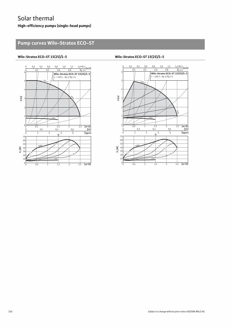
310 Subject to change without prior notice 09/2006 WILO AG
Solar thermalHigh-efficiency pumps (single-head pumps)
Pump curves Wilo-Stratos ECO-ST
Wilo-Stratos ECO-ST 15(25)/1-5 Wilo-Stratos ECO-ST 15(25)/1-5
max.
H [m
]
0
4
5
6
2
1
3
[m/s]0 0,8 0,2 0,4
0,2 0 0,4 0,6 0,8 1,0 1,2 1,4
0,6
0 0,5
0 0,2 0,4 0,6
0 2 4 6 8
1 1,5 2 2,5
[m³/h]1,5 1 2,5 2 0 0,5
[m³/h][l/s]
[lgpm]
0
40
30
20
10
50
60
70
P 1[W
]
Q
4 m
3 m
2 m
1 m
p-c
max.
min.
min.
5 m
Rp 1¼
Rp 1
Wilo-Stratos ECO-ST 15(25)/1-51 ~ 230 V - Rp 1/ Rp 1¼
max.
H [m
]
0
4
5
6
2
1
3
[m/s]0 0,8 0,2 0,4
0,2 0 0,4 0,6 0,8 1,0 1,2 1,4
0,6
0 0,5
0 0,2 0,4 0,6
0 2 4 6 8
1 1,5 2 2,5
[m³/h]1,5 1 2,5 2 0 0,5
[m³/h][l/s]
[lgpm]
0
40
30
20
10
50
60
70
P 1 [W
]
Q
4 m
3 m
2 m
1 m
p-v
ma
x.
min.
min.
5 m
Rp 1¼
Rp 1
Wilo-Stratos ECO-ST 15(25)/1-51 ~ 230 V - Rp 1/ Rp 1¼
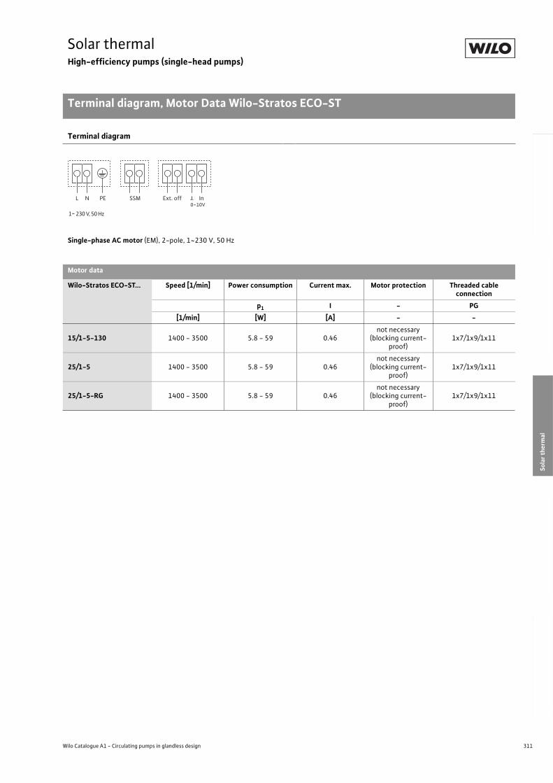
311
Solar thermalHigh-efficiency pumps (single-head pumps)
Terminal diagram, Motor Data Wilo-Stratos ECO-ST
Wilo Catalogue A1 - Circulating pumps in glandless design
Hea
tin
g, A
ir-c
on
dit
ion
ing
, C
oo
ling
Po
tab
le w
ater
cir
cula
tio
nSo
lar
ther
mal
Serv
ice/
Acc
esso
ries
, Sys
tem
sSw
itch
gea
rs a
nd
Co
ntr
ol
Dev
ices
P
um
p M
anag
emen
t S y
stem
s
Terminal diagram
Single-phase AC motor (EM), 2-pole, 1~230 V, 50 Hz
Motor data
Wilo-Stratos ECO-ST... Speed [1/min] Power consumption Current max. Motor protection Threaded cable connection
p1 I - PG
[1/min] [W] [A] - -
15/1-5-130 1400 - 3500 5.8 - 59 0.46not necessary
(blocking current-proof)
1x7/1x9/1x11
25/1-5 1400 - 3500 5.8 - 59 0.46not necessary
(blocking current-proof)
1x7/1x9/1x11
25/1-5-RG 1400 - 3500 5.8 - 59 0.46not necessary
(blocking current-proof)
1x7/1x9/1x11
0~10V
L N PE SSM InExt. off
1~ 230 V, 50 Hz
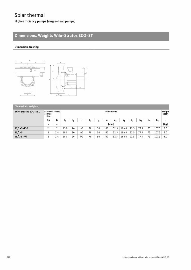
312 Subject to change without prior notice 09/2006 WILO AG
Solar thermalHigh-efficiency pumps (single-head pumps)
Dimensions, Weights Wilo-Stratos ECO-ST
Dimension drawing
Dimensions, Weights
Wilo-Stratos ECO-ST... Screwed connec-
tion
Thread Dimensions Weight about
Rp G l0 l1 l3 l4 l5 a a2 b1 b2 b3 b4 b5 -
- - [mm] [kg]
15/1-5-130 ½ 1 130 96 90 78 50 60 32.5 184.8 92.5 77.5 73 107.3 3.0
25/1-5 1 1½ 180 96 90 78 50 60 32.5 184.8 92.5 77.5 73 107.3 3.0
25/1-5-RG 1 1½ 180 96 90 78 50 60 32.5 184.8 92.5 77.5 73 107.3 3.0
b1
b3
b2
b5 G
a2
I4 I5
I1
I 0
l 3
b4
313
Solar thermalHigh-efficiency pumps (single-head pumps)
Wilo Catalogue A1 - Circulating pumps in glandless design
Hea
tin
g, A
ir-c
on
dit
ion
ing
, C
oo
ling
Po
tab
le w
ater
cir
cula
tio
nSo
lar
ther
mal
Serv
ice/
Acc
esso
ries
, Sys
tem
sSw
itch
gea
rs a
nd
Co
ntr
ol
Dev
ices
P
um
p M
anag
emen
t S y
stem
s
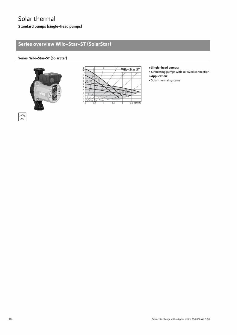
314 Subject to change without prior notice 09/2006 WILO AG
Solar thermalStandard pumps (single-head pumps)
Series overview Wilo-Star-ST (SolarStar)
Series: Wilo-Star-ST (SolarStar)
>Single-head pumps:• Circulating pumps with screwed connection
>Application:• Solar thermal systems
0 0,5 1 1,5 2,5201
23
4
56
7
89
10Wilo-Star ST
ST 20/9
ST 20/11
ST 25/4
ST 25/6
ST 25/7
Q[m3/h]
H[m
]

315
Solar thermalStandard pumps (single-head pumps)
Series overview Wilo-Star-ST (SolarStar)
Wilo Catalogue A1 - Circulating pumps in glandless design
Hea
tin
g, A
ir-c
on
dit
ion
ing
, C
oo
ling
Po
tab
le w
ater
cir
cula
tio
nSo
lar
ther
mal
Serv
ice/
Acc
esso
ries
, Sys
tem
sSw
itch
gea
rs a
nd
Co
ntr
ol
Dev
ices
P
um
p M
anag
emen
t S y
stem
s
Series: Wilo-Star-ST (SolarStar)
> Product advantages:• Special hydraulics for utilisation in solar thermal systems
• Up to 30% lower current consumption
• Pump housing with wrench attachment point
• Pump housing with cataphoretic (KTL) painting for the prevention of corrosion from conden-
sation formation
> Additional information: Page:• Planning Guide: . . . . . . . . . . . . . . . . . . 6
• Equipment/Function: . . . . . . . . . . . . . 316
• Technical Data: . . . . . . . . . . . . . . . . . . 318
• Pump curves: . . . . . . . . . . . . . . . . . . . . 320
• Terminal Diagrams, Motor Data: . . . 322
• Dimensions, Weights: . . . . . . . . . . . . . 323
• Service/Accessories: . . . . . . . . . . . . . . 325
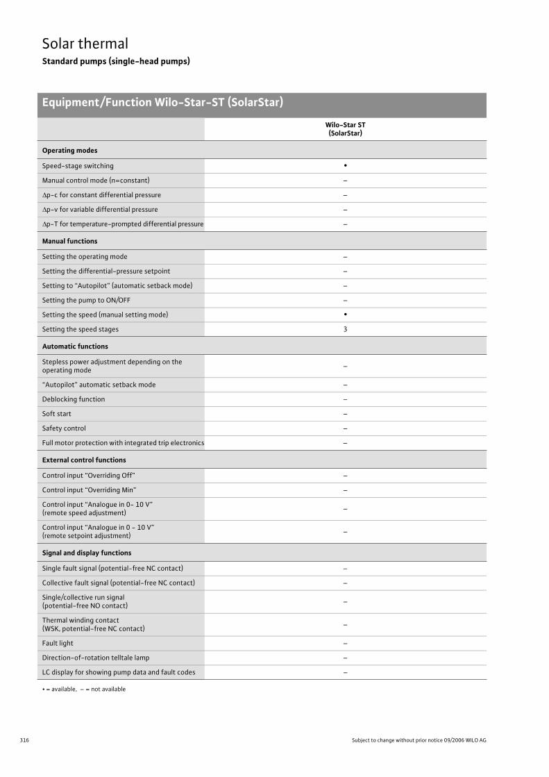
316 Subject to change without prior notice 09/2006 WILO AG
Solar thermalStandard pumps (single-head pumps)
Equipment/Function Wilo-Star-ST (SolarStar)
Wilo-Star ST(SolarStar)
Operating modes
Speed-stage switching •
Manual control mode (n=constant) –
p-c for constant differential pressure –
p-v for variable differential pressure –
p-T for temperature-prompted differential pressure –
Manual functions
Setting the operating mode –
Setting the differential-pressure setpoint –
Setting to “Autopilot” (automatic setback mode) –
Setting the pump to ON/OFF –
Setting the speed (manual setting mode) •
Setting the speed stages 3
Automatic functions
Stepless power adjustment depending on the operating mode
–
“Autopilot” automatic setback mode –
Deblocking function –
Soft start –
Safety control –
Full motor protection with integrated trip electronics –
External control functions
Control input “Overriding Off” –
Control input “Overriding Min” –
Control input “Analogue in 0- 10 V” (remote speed adjustment)
–
Control input “Analogue in 0 - 10 V” (remote setpoint adjustment)
–
Signal and display functions
Single fault signal (potential-free NC contact) –
Collective fault signal (potential-free NC contact) –
Single/collective run signal (potential-free NO contact)
–
Thermal winding contact (WSK, potential-free NC contact)
–
Fault light –
Direction-of-rotation telltale lamp –
LC display for showing pump data and fault codes –
• = available, – = not available
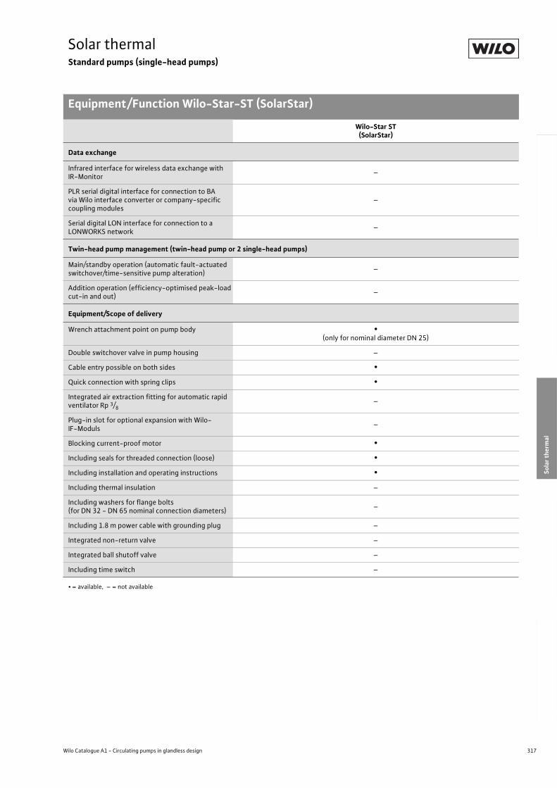
317
Solar thermalStandard pumps (single-head pumps)
Equipment/Function Wilo-Star-ST (SolarStar)
Wilo Catalogue A1 - Circulating pumps in glandless design
Hea
tin
g, A
ir-c
on
dit
ion
ing
, C
oo
ling
Po
tab
le w
ater
cir
cula
tio
nSo
lar
ther
mal
Serv
ice/
Acc
esso
ries
, Sys
tem
sSw
itch
gea
rs a
nd
Co
ntr
ol
Dev
ices
P
um
p M
anag
emen
t S y
stem
s
Data exchange
Infrared interface for wireless data exchange with IR-Monitor
–
PLR serial digital interface for connection to BA via Wilo interface converter or company-specific coupling modules
–
Serial digital LON interface for connection to a LONWORKS network
–
Twin-head pump management (twin-head pump or 2 single-head pumps)
Main/standby operation (automatic fault-actuated switchover/time-sensitive pump alteration)
–
Addition operation (efficiency-optimised peak-load cut-in and out)
–
Equipment/Scope of delivery
Wrench attachment point on pump body •(only for nominal diameter DN 25)
Double switchover valve in pump housing –
Cable entry possible on both sides •
Quick connection with spring clips •
Integrated air extraction fitting for automatic rapid ventilator Rp 3/8
–
Plug-in slot for optional expansion with Wilo-IF-Moduls
–
Blocking current-proof motor •
Including seals for threaded connection (loose) •
Including installation and operating instructions •
Including thermal insulation –
Including washers for flange bolts(for DN 32 - DN 65 nominal connection diameters)
–
Including 1.8 m power cable with grounding plug –
Integrated non-return valve –
Integrated ball shutoff valve –
Including time switch –
Wilo-Star ST(SolarStar)
• = available, – = not available
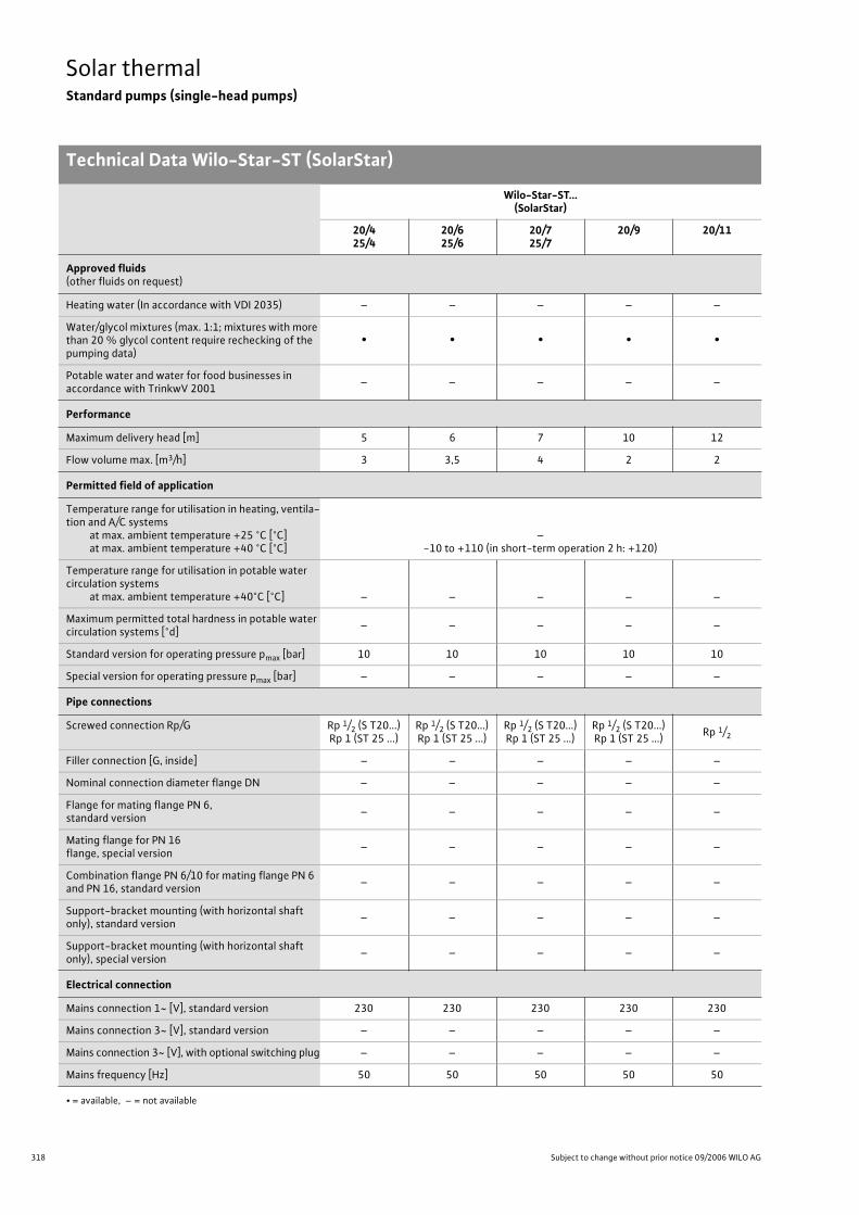
318 Subject to change without prior notice 09/2006 WILO AG
Solar thermalStandard pumps (single-head pumps)
Technical Data Wilo-Star-ST (SolarStar)
Wilo-Star-ST...(SolarStar)
20/425/4
20/625/6
20/725/7
20/9 20/11
Approved fluids(other fluids on request)
Heating water (In accordance with VDI 2035) – – – – –
Water/glycol mixtures (max. 1:1; mixtures with more than 20 % glycol content require rechecking of the pumping data)
• • • • •
Potable water and water for food businesses in accordance with TrinkwV 2001
– – – – –
Performance
Maximum delivery head [m] 5 6 7 10 12
Flow volume max. [m3/h] 3 3,5 4 2 2
Permitted field of application
Temperature range for utilisation in heating, ventila-tion and A/C systems
at max. ambient temperature +25 °C [°C]at max. ambient temperature +40 °C [°C]
–-10 to +110 (in short-term operation 2 h: +120)
Temperature range for utilisation in potable water circulation systems
at max. ambient temperature +40°C [°C] – – – – –
Maximum permitted total hardness in potable water circulation systems [°d]
– – – – –
Standard version for operating pressure pmax [bar] 10 10 10 10 10
Special version for operating pressure pmax [bar] – – – – –
Pipe connections
Screwed connection Rp/G Rp 1/2 (S T20...)Rp 1 (ST 25 ...)
Rp 1/2 (S T20...)Rp 1 (ST 25 ...)
Rp 1/2 (S T20...)Rp 1 (ST 25 ...)
Rp 1/2 (S T20...)Rp 1 (ST 25 ...)
Rp 1/2
Filler connection [G, inside] – – – – –
Nominal connection diameter flange DN – – – – –
Flange for mating flange PN 6, standard version
– – – – –
Mating flange for PN 16 flange, special version
– – – – –
Combination flange PN 6/10 for mating flange PN 6 and PN 16, standard version
– – – – –
Support-bracket mounting (with horizontal shaft only), standard version
– – – – –
Support-bracket mounting (with horizontal shaft only), special version
– – – – –
Electrical connection
Mains connection 1~ [V], standard version 230 230 230 230 230
Mains connection 3~ [V], standard version – – – – –
Mains connection 3~ [V], with optional switching plug – – – – –
Mains frequency [Hz] 50 50 50 50 50
• = available, – = not available
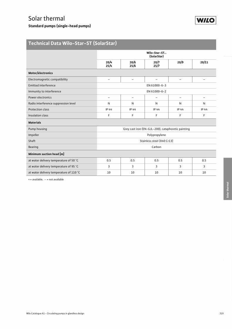
319
Solar thermalStandard pumps (single-head pumps)
Technical Data Wilo-Star-ST (SolarStar)
Wilo Catalogue A1 - Circulating pumps in glandless design
Hea
tin
g, A
ir-c
on
dit
ion
ing
, C
oo
ling
Po
tab
le w
ater
cir
cula
tio
nSo
lar
ther
mal
Serv
ice/
Acc
esso
ries
, Sys
tem
sSw
itch
gea
rs a
nd
Co
ntr
ol
Dev
ices
P
um
p M
anag
emen
t S y
stem
s
Motor/electronics
Electromagnetic compatibility – – – – –
Emitted interference EN 61000-6-3
Immunity to interference EN 61000-6-2
Power electronics – – – – –
Radio interference suppression level N N N N N
Protection class IP 44 IP 44 IP 44 IP 44 IP 44
Insulation class F F F F F
Materials
Pump housing Grey cast iron (EN-GJL-200), cataphoretic painting
Impeller Polypropylene
Shaft Stainless steel (X40 Cr13)
Bearing Carbon
Minimum suction head [m]
at water delivery temperature of 50 °C 0.5 0.5 0.5 0.5 0.5
at water delivery temperature of 95 °C 3 3 3 3 3
at water delivery temperature of 110 °C 10 10 10 10 10
Wilo-Star-ST...(SolarStar)
20/425/4
20/625/6
20/725/7
20/9 20/11
• = available, – = not available
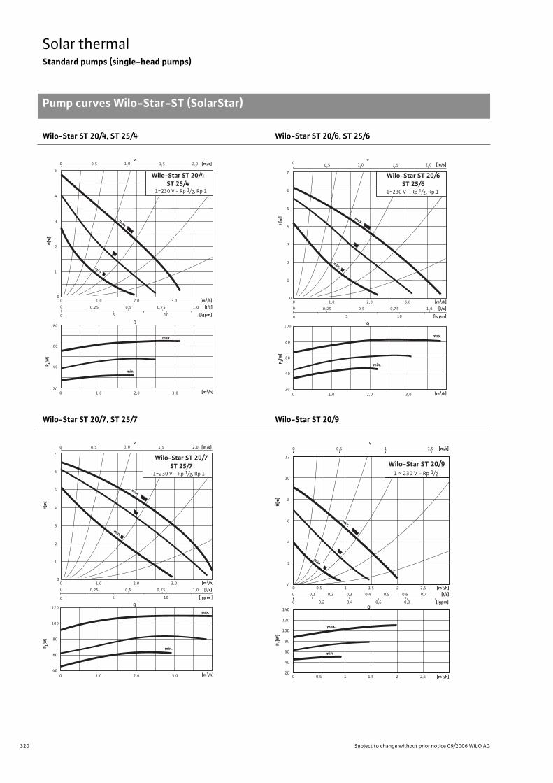
320 Subject to change without prior notice 09/2006 WILO AG
Solar thermalStandard pumps (single-head pumps)
Pump curves Wilo-Star-ST (SolarStar)
Wilo-Star ST 20/4, ST 25/4 Wilo-Star ST 20/6, ST 25/6
Wilo-Star ST 20/7, ST 25/7 Wilo-Star ST 20/9
Q
0,5 0
0 0
0
0
[l/s]
[lgpm]
0 20
0,75
1,0
[m/s]
1
2
5
v 1,0 1,5
10 5
80
60
40
1,0 2,0 3,0
0,25 0,5 1,0
2,0 3,0
4
3 max
min
min
max
2,0
Wilo-Star ST 20/4 ST 25/4
1~230 V - Rp 1/2, Rp 1
P 1[W]
H[m
]
[m3/h]
[m3/h]
Q
0,5 0
0 0
0
0
[l/s]
[lgpm]
0 20
0,75
1,0
[m/s]
1
2
5
v 1,0 1,5
10 5
100
80
60
1,0 2,0 3,0
0,25 0,5 1,0
2,0 3,0
4
3
6
max.
min.
40
7
min.
max.
2,0
Wilo-Star ST 20/6 ST 25/6
1~230 V - Rp 1/2, Rp 1
[m3/h]
[m3/h]
P 1[W]
H[m
]
Q
0,5 0
0 0
0
0
[l/s]
[lgpm ]
0 40
0,75
1,0
[m/s]
1
2
5
v 1,0 1,5
10 5
120
100
80
1,0 2,0 3,0
0,25 0,5 1,0
2,0 3,0
4
3
6
max.
min.
60
7
min.
max.
2,0
Wilo-Star ST 20/7 ST 25/7
1~230 V - Rp 1/2, Rp 1
[m3/h]
[m3/h]
P 1[W]
H[m
]
140
120
100
80
60
40
20
0 0,1 0,2 0,3 0,4 0,5 0,6 0,7
0 0,2 0,4 0,6 0,8
0 0,5 1 1,5
0 0,5 1 1,5 2 2,5
v [m/s]
Q
[m3/h]
[lgpm]
12
10
8
6
4
2
0
[l/s]
Wilo-Star ST 20/91 ~ 230 V - Rp 1/2
[m3/h]
max.
min
max.
min
0 0,5 1 1,5 2 2,5
P 1[W]
H[m
]
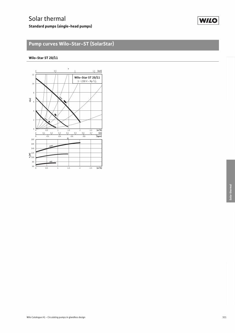
321
Solar thermalStandard pumps (single-head pumps)
Pump curves Wilo-Star-ST (SolarStar)
Wilo Catalogue A1 - Circulating pumps in glandless design
Hea
tin
g, A
ir-c
on
dit
ion
ing
, C
oo
ling
Po
tab
le w
ater
cir
cula
tio
nSo
lar
ther
mal
Serv
ice/
Acc
esso
ries
, Sys
tem
sSw
itch
gea
rs a
nd
Co
ntr
ol
Dev
ices
P
um
p M
anag
emen
t S y
stem
s
Wilo-Star ST 20/11
Q
max.
[m3/h]
0 0,1 0,2 0,3 0,4 0,5 0,6 0,7
0 0,2 0,4 0,6 0,8
0 0,5 1 1,5
0 0,5 1 1,5 2 2,5
v [m/s]
[m3/h]
[lgpm]
12
10
8
6
4
2
0
[l/s]
Wilo-Star ST 20/111 ~ 230 V - Rp 1/2
max.
min
0 0,5 1 1,5 2 2,5
180
160
140
120
100
80
60
min
P 1[W]
H[m
]
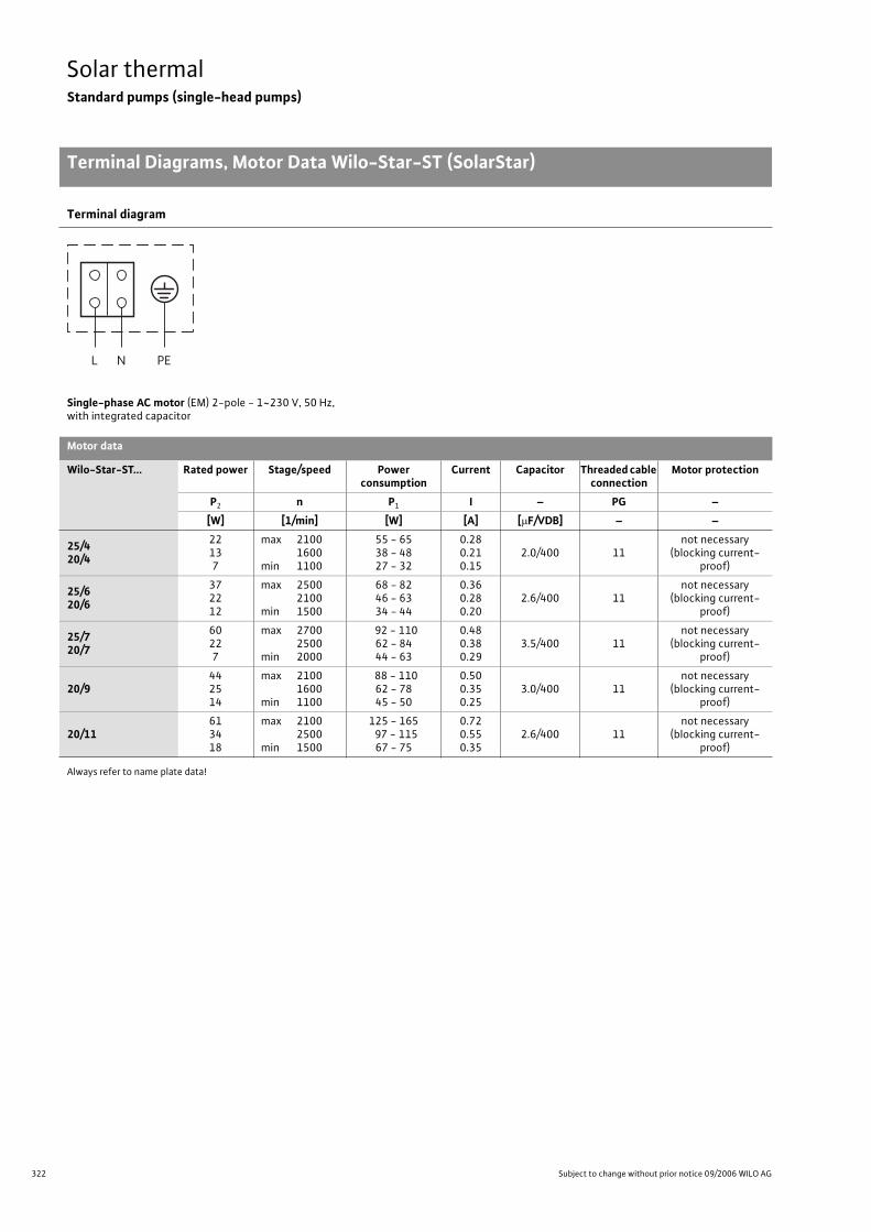
322 Subject to change without prior notice 09/2006 WILO AG
Solar thermalStandard pumps (single-head pumps)
Terminal Diagrams, Motor Data Wilo-Star-ST (SolarStar)
Always refer to name plate data!
Terminal diagram
Single-phase AC motor (EM) 2-pole - 1~230 V, 50 Hz,with integrated capacitor
Motor data
Wilo-Star-ST... Rated power Stage/speed Power consumption
Current Capacitor Threaded cable connection
Motor protection
P2 n P1 I – PG –
[W] [1/min] [W] [A] [ F/VDB] – –
25/420/4
22137
max 2100 1600
min 1100
55 - 6538 - 4827 - 32
0.280.210.15
2.0/400 11not necessary
(blocking current-proof)
25/620/6
372212
max 25002100
min 1500
68 - 8246 - 6334 - 44
0.360.280.20
2.6/400 11not necessary
(blocking current-proof)
25/720/7
60227
max 2700 2500
min 2000
92 - 11062 - 8444 - 63
0.480.380.29
3.5/400 11not necessary
(blocking current-proof)
20/9442514
max 2100 1600
min 1100
88 - 11062 - 7845 - 50
0.500.350.25
3.0/400 11not necessary
(blocking current-proof)
20/11613418
max 2100 2500
min 1500
125 - 165 97 - 115
67 - 75
0.720.550.35
2.6/400 11not necessary
(blocking current-proof)
L N PE
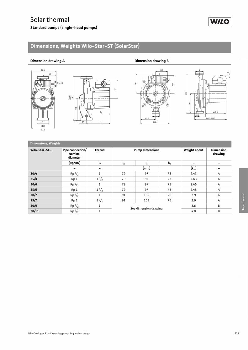
323
Solar thermalStandard pumps (single-head pumps)
Dimensions, Weights Wilo-Star-ST (SolarStar)
Wilo Catalogue A1 - Circulating pumps in glandless design
Hea
tin
g, A
ir-c
on
dit
ion
ing
, C
oo
ling
Po
tab
le w
ater
cir
cula
tio
nSo
lar
ther
mal
Serv
ice/
Acc
esso
ries
, Sys
tem
sSw
itch
gea
rs a
nd
Co
ntr
ol
Dev
ices
P
um
p M
anag
emen
t S y
stem
s
Dimension drawing A Dimension drawing B
Dimensions, Weights
Wilo-Star-ST... Pipe connection/Nominal diameter
Thread Pump dimensions Weight about Dimension drawing
[Rp/DN] G I0 l1 b3 – –
– – [mm] [kg] –
20/4 Rp 1/2 1 79 97 73 2.43 A
25/4 Rp 1 1 1/2 79 97 73 2.43 A
20/6 Rp 1/2 1 79 97 73 2.45 A
25/6 Rp 1 1 1/2 79 97 73 2.45 A
20/7 Rp 1/2 1 91 109 76 2.9 A
25/7 Rp 1 1 1/2 91 109 76 2.9 A
20/9 Rp 1/2 1See dimension drawing
3.6 B
20/11 Rp 1/2 1 4.0 B
180
l0
b3
l1
90
92,5
100
PG 11
54
33G
(Rp)
(130
)53,7
90
78,8
67,2
130,4
G
180
90
91 (79)
3
141,5 (129)
22,5G

324 Subject to change without prior notice 09/2006 WILO AG
Solar thermalStandard pumps (single-head pumps)
325
Service/AccessoriesContents
Wilo Catalogue A1 - Circulating pumps in glandless design
Hea
tin
g, A
ir-c
on
dit
ion
ing
, C
oo
ling
Po
tab
le w
ater
cir
cula
tio
nSo
lar
ther
mal
Serv
ice/
Acc
esso
ries
, Sys
tem
sSw
itch
gea
rs a
nd
Co
ntr
ol
Dev
ices
P
um
p M
anag
emen
t S y
stem
s
Service/Accessories
Wilo-TOP Motor Technology 326
Circuit diagrams 328
Switching plug/servicing apparatus 331
Threaded Pipe Unions 332
Adapter Fittings Wilo-(R), Wilo-(RF), Wilo-(F) 334
Pump Thermal Insulation 336
Cold water insulation for pumps Wilo-ClimaForm 337
Wilo-TOP Modular Concept (Motor-Modules) 340
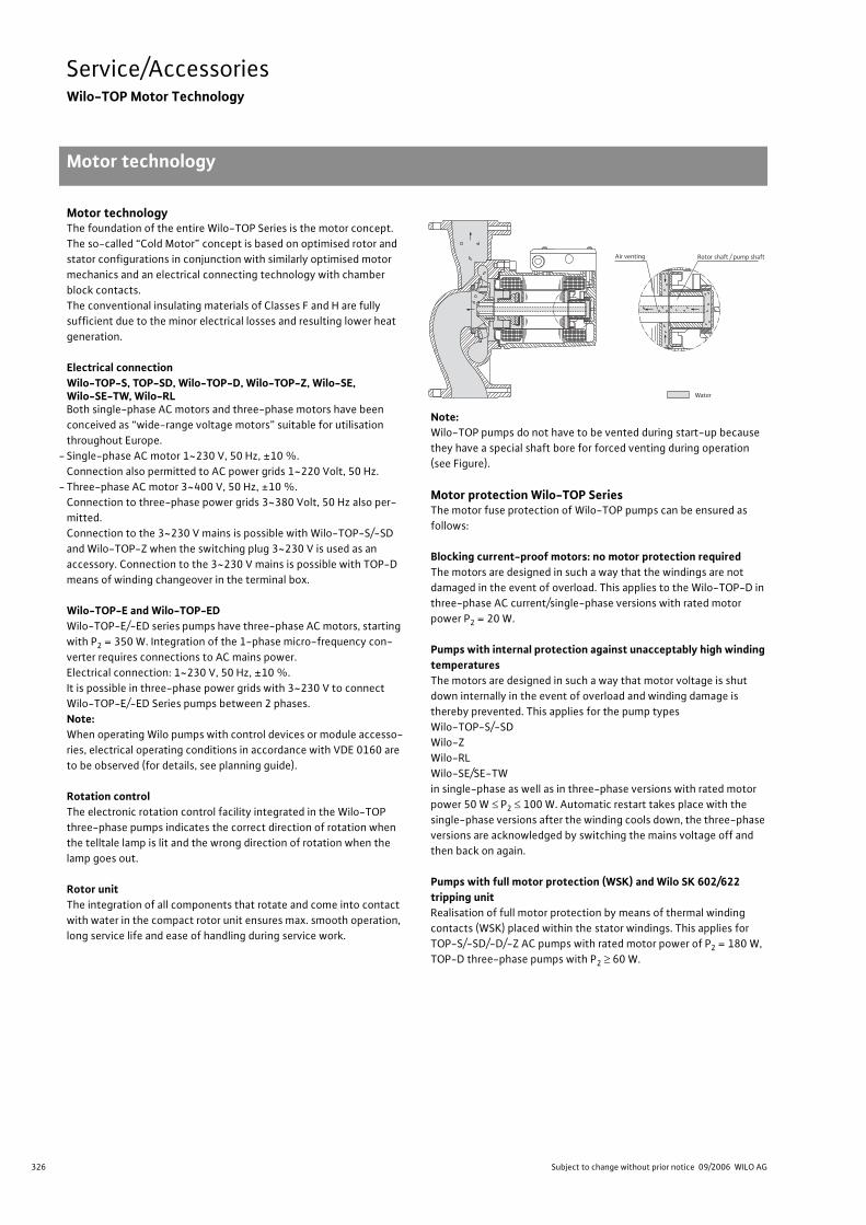
326 Subject to change without prior notice 09/2006 WILO AG
Service/AccessoriesWilo-TOP Motor Technology
Motor technology
Motor technologyThe foundation of the entire Wilo-TOP Series is the motor concept.
The so-called “Cold Motor” concept is based on optimised rotor and
stator configurations in conjunction with similarly optimised motor
mechanics and an electrical connecting technology with chamber
block contacts.
The conventional insulating materials of Classes F and H are fully
sufficient due to the minor electrical losses and resulting lower heat
generation.
Electrical connectionWilo-TOP-S, TOP-SD, Wilo-TOP-D, Wilo-TOP-Z, Wilo-SE, Wilo-SE-TW, Wilo-RLBoth single-phase AC motors and three-phase motors have been
conceived as “wide-range voltage motors” suitable for utilisation
throughout Europe.
- Single-phase AC motor 1~230 V, 50 Hz, ±10 %.
Connection also permitted to AC power grids 1~220 Volt, 50 Hz.
- Three-phase AC motor 3~400 V, 50 Hz, ±10 %.
Connection to three-phase power grids 3~380 Volt, 50 Hz also per-
mitted.
Connection to the 3~230 V mains is possible with Wilo-TOP-S/-SD
and Wilo-TOP-Z when the switching plug 3~230 V is used as an
accessory. Connection to the 3~230 V mains is possible with TOP-D
means of winding changeover in the terminal box.
Wilo-TOP-E and Wilo-TOP-EDWilo-TOP-E/-ED series pumps have three-phase AC motors, starting
with P2 = 350 W. Integration of the 1-phase micro-frequency con-
verter requires connections to AC mains power.
Electrical connection: 1~230 V, 50 Hz, ±10 %.
It is possible in three-phase power grids with 3~230 V to connect
Wilo-TOP-E/-ED Series pumps between 2 phases.
Note:When operating Wilo pumps with control devices or module accesso-
ries, electrical operating conditions in accordance with VDE 0160 are
to be observed (for details, see planning guide).
Rotation controlThe electronic rotation control facility integrated in the Wilo-TOP
three-phase pumps indicates the correct direction of rotation when
the telltale lamp is lit and the wrong direction of rotation when the
lamp goes out.
Rotor unitThe integration of all components that rotate and come into contact
with water in the compact rotor unit ensures max. smooth operation,
long service life and ease of handling during service work.
Note:Wilo-TOP pumps do not have to be vented during start-up because
they have a special shaft bore for forced venting during operation
(see Figure).
Motor protection Wilo-TOP SeriesThe motor fuse protection of Wilo-TOP pumps can be ensured as
follows:
Blocking current-proof motors: no motor protection requiredThe motors are designed in such a way that the windings are not
damaged in the event of overload. This applies to the Wilo-TOP-D in
three-phase AC current/single-phase versions with rated motor
power P2 = 20 W.
Pumps with internal protection against unacceptably high winding temperaturesThe motors are designed in such a way that motor voltage is shut
down internally in the event of overload and winding damage is
thereby prevented. This applies for the pump types
Wilo-TOP-S/-SD
Wilo-Z
Wilo-RL
Wilo-SE/SE-TW
in single-phase as well as in three-phase versions with rated motor
power 50 W P2 100 W. Automatic restart takes place with the
single-phase versions after the winding cools down, the three-phase
versions are acknowledged by switching the mains voltage off and
then back on again.
Pumps with full motor protection (WSK) and Wilo SK 602/622 tripping unitRealisation of full motor protection by means of thermal winding
contacts (WSK) placed within the stator windings. This applies for
TOP-S/-SD/-D/-Z AC pumps with rated motor power of P2 = 180 W,
TOP-D three-phase pumps with P2 60 W.
Water
Rotor shaft / pump shaftAir venting
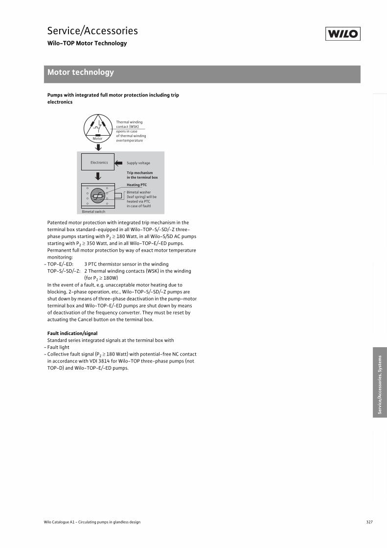
327
Service/AccessoriesWilo-TOP Motor Technology
Motor technology
Wilo Catalogue A1 - Circulating pumps in glandless design
Hea
tin
g, A
ir-c
on
dit
ion
ing
, C
oo
ling
Po
tab
le w
ater
cir
cula
tio
nSo
lar
ther
mal
Serv
ice/
Acc
esso
ries
, Sys
tem
sSw
itch
gea
rs a
nd
Co
ntr
ol
Dev
ices
P
um
p M
anag
emen
t S y
stem
s
Pumps with integrated full motor protection including trip electronics
Patented motor protection with integrated trip mechanism in the
terminal box standard-equipped in all Wilo-TOP-S/-SD/-Z three-
phase pumps starting with P2 180 Watt, in all Wilo-S/SD AC pumps
starting with P2 350 Watt, and in all Wilo-TOP-E/-ED pumps.
Permanent full motor protection by way of exact motor temperature
monitoring:
- TOP-E/-ED: 3 PTC thermistor sensor in the winding
TOP-S/-SD/-Z: 2 Thermal winding contacts (WSK) in the winding
(for P2 180W)
In the event of a fault, e.g. unacceptable motor heating due to
blocking, 2-phase operation, etc., Wilo-TOP-S/-SD/-Z pumps are
shut down by means of three-phase deactivation in the pump-motor
terminal box and Wilo-TOP-E/-ED pumps are shut down by means
of deactivation of the frequency converter. They must be reset by
actuating the Cancel button on the terminal box.
Fault indication/signalStandard series integrated signals at the terminal box with
- Fault light
- Collective fault signal (P2 180 Watt) with potential-free NC contact
in accordance with VDI 3814 for Wilo-TOP three-phase pumps (not
TOP-D) and Wilo-TOP-E/-ED pumps.
Electronics Supply voltage
Trip mechanismin the terminal box
Heating PTC
Bimetal washer (leaf spring) will be heated via PTC in case of faultl
Bimetal switch
Thermal windingcontact (WSK)opens in case of thermal winding overtemperature
Motor
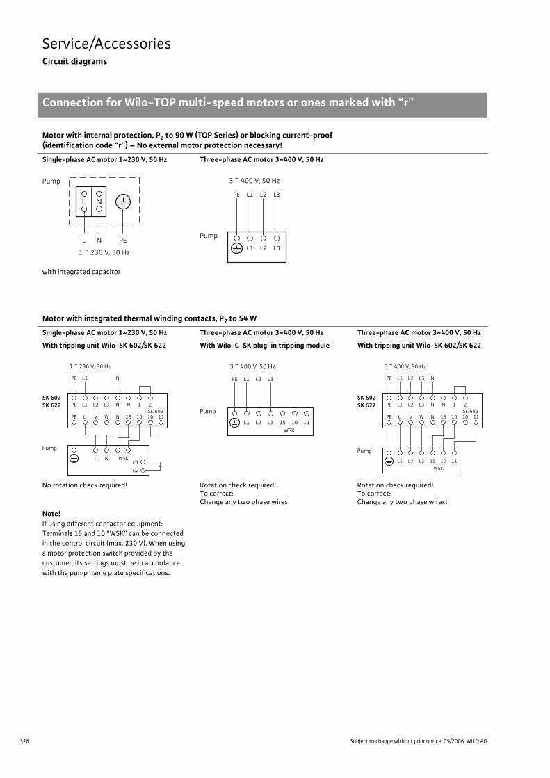
328 Subject to change without prior notice 09/2006 WILO AG
Service/AccessoriesCircuit diagrams
Connection for Wilo-TOP multi-speed motors or ones marked with “r”
Motor with internal protection, P2 to 90 W (TOP Series) or blocking current-proof(identification code “r”) – No external motor protection necessary!
Single-phase AC motor 1~230 V, 50 Hz Three-phase AC motor 3~400 V, 50 Hz
with integrated capacitor
Motor with integrated thermal winding contacts, P2 to 54 W
Single-phase AC motor 1~230 V, 50 Hz Three-phase AC motor 3~400 V, 50 Hz Three-phase AC motor 3~400 V, 50 Hz
With tripping unit Wilo-SK 602/SK 622 With Wilo-C-SK plug-in tripping module With tripping unit Wilo-SK 602/SK 622
No rotation check required! Rotation check required!To correct:Change any two phase wires!
Rotation check required!To correct:Change any two phase wires!
Note!If using different contactor equipment:
Terminals 15 and 10 “WSK” can be connected
in the control circuit (max. 230 V). When using
a motor protection switch provided by the
customer, its settings must be in accordance
with the pump name plate specifications.
L
L
N
N PE
Pump
1 ~ 230 V, 50 Hz
PE L1 L2 L3
L1 L2 L3
Pump
3 ~ 400 V, 50 Hz
PE
PE
U
L1
V
L2
W
L3
N
N
PE L1 N
15
N
10
1
L N WSKC1
C2
10SK 6022
11
Pump
SK 602SK 622
1 ~ 230 V, 50 Hz
PE L1 L2 L3
L1 L2 L3 15WSK
10 11
Pump
3 ~ 400 V, 50 Hz
PE
PE
U
L1
V
L2
W
L3
N
N
PE L1 L2 L3 N
15
N
10
1
L1 L2 L3 15WSK
10 11
10SK 6022
11
Pump
SK 602SK 622
3 ~ 400 V, 50 Hz
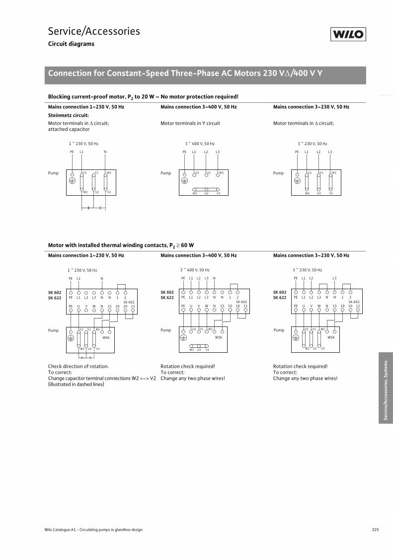
329
Service/AccessoriesCircuit diagrams
Connection for Constant-Speed Three-Phase AC Motors 230 V /400 V Y
Wilo Catalogue A1 - Circulating pumps in glandless design
Hea
tin
g, A
ir-c
on
dit
ion
ing
, C
oo
ling
Po
tab
le w
ater
cir
cula
tio
nSo
lar
ther
mal
Serv
ice/
Acc
esso
ries
, Sys
tem
sSw
itch
gea
rs a
nd
Co
ntr
ol
Dev
ices
P
um
p M
anag
emen
t S y
stem
s
Blocking current-proof motor, P2 to 20 W – No motor protection required!
Mains connection 1~230 V, 50 Hz Mains connection 3~400 V, 50 Hz Mains connection 3~230 V, 50 Hz
Steinmetz circuit:
Motor terminals in circuit;attached capacitor
Motor terminals in Y circuit Motor terminals in circuit;
Motor with installed thermal winding contacts, P2 60 W
Mains connection 1~230 V, 50 Hz Mains connection 3~400 V, 50 Hz Mains connection 3~230 V, 50 Hz
Check direction of rotation.To correct:Change capacitor terminal connections W2 <–> V2 (illustrated in dashed lines)
Rotation check required!To correct:Change any two phase wires!
Rotation check required!To correct:Change any two phase wires!
PE L1 N
U1 V1 W1
W2 U2 V2
Pump
1 ~ 230 V, 50 Hz
PE L1 L2 L3
U1 V1 W1
W2 U2 V2
Pump
3 ~ 400 V, 50 Hz
PE L1 L2 L3
U1 V1 W1
W2 U2 V2
Pump
3 ~ 230 V, 50 Hz
PE
PE
U
L1
V
L2
W
L3
N
N
PE L1 N
15
N
10
1
U1 V1 W1
W2 U2 V2
WSK
10SK 6022
11
Pump
SK 602SK 622
1 ~ 230 V, 50 Hz
PE
PE
U
L1
V
L2
W
L3
N
N
PE L1 L2 L3 N
15
N
10
1
U1 V1 W1
W2 U2 V2
WSK
10SK 6022
11
Pump
SK 602SK 622
3 ~ 400 V, 50 Hz
PE
PE
U
L1
V
L2
W
L3
N
N
PE L1 L2 L3
15
N
10
1
U1 V1 W1
W2 U2 V2
WSK
10SK 6022
11
Pump
SK 602SK 622
3 ~ 230 V, 50 Hz
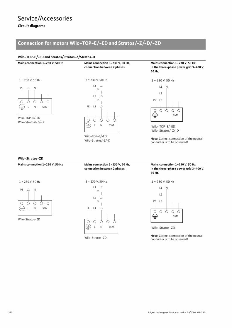
330 Subject to change without prior notice 09/2006 WILO AG
Service/AccessoriesCircuit diagrams
Connection for motors Wilo-TOP-E/-ED and Stratos/-Z/-D/-ZD
Wilo-TOP-E/-ED and Stratos/Stratos-Z/Stratos-D
Mains connection 1~230 V, 50 Hz Mains connection 3~230 V, 50 Hz, connection between 2 phases
Mains connection 1~230 V, 50 Hzin the three-phase power grid 3~400 V, 50 Hz,
Note: Correct connection of the neutral conductor is to be observed!
Wilo-Stratos-ZD
Mains connection 1~230 V, 50 Hz Mains connection 3~230 V, 50 Hz, connection between 2 phases
Mains connection 1~230 V, 50 Hz,in the three-phase power grid 3~400 V, 50 Hz,
Note: Correct connection of the neutral conductor is to be observed!
Connec-tion for motors Wilo-TOP-E/-ED and Stratos/-Z/-D/-ZD
PE L1 N
L N SSM
Wilo-TOP-E/-EDWilo-Stratos/-Z/-D
1 ~ 230 V, 50 Hz
PE L1 L3
L2 L3or
L1 L2or
L N SSM
Wilo-TOP-E/-EDWilo-Stratos/-Z/-D
3 ~ 230 V, 50 Hz
PE L3
L2
L1 N
SSM
1 ~ 230 V, 50 Hz
Wilo-TOP-E/-ED
Wilo-Stratos/-Z/-D
PE L1 N
L N SSM
Wilo-Stratos-ZD
1 ~ 230 V, 50 Hz
PE L1 L3
L2 L3or
L1 L2or
L N SSM
Wilo-Stratos-ZD
3 ~ 230 V, 50 Hz
PE L3
L2
L1 N
SSM
1 ~ 230 V, 50 Hz
Wilo-Stratos-ZD
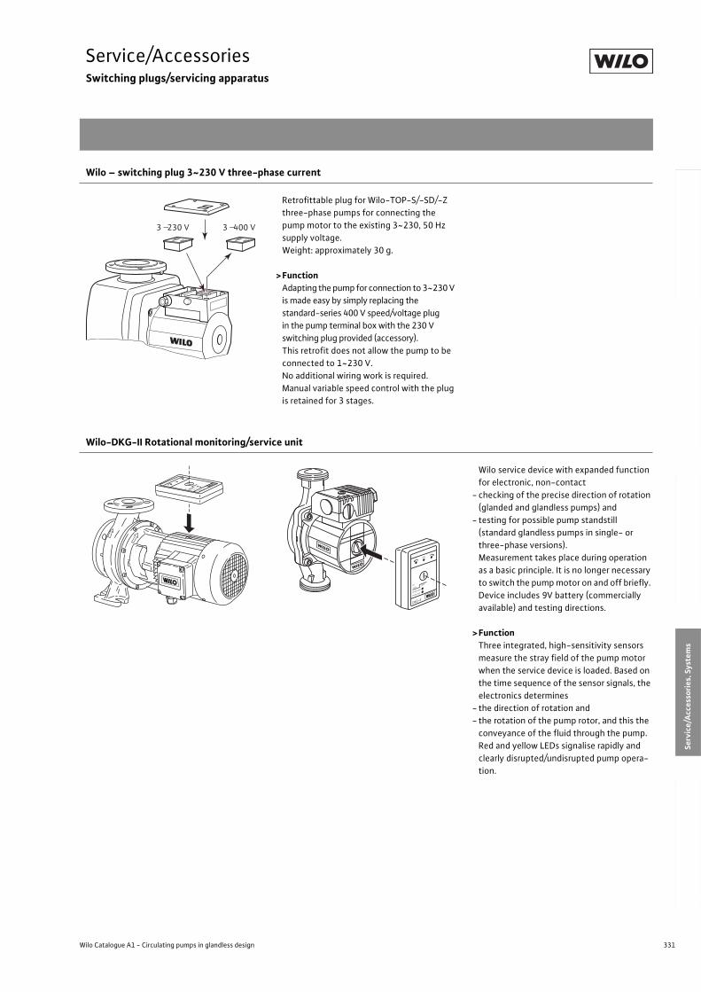
331
Service/AccessoriesSwitching plugs/servicing apparatus
Wilo Catalogue A1 - Circulating pumps in glandless design
Hea
tin
g, A
ir-c
on
dit
ion
ing
, C
oo
ling
Po
tab
le w
ater
cir
cula
tio
nSo
lar
ther
mal
Serv
ice/
Acc
esso
ries
, Sys
tem
sSw
itch
gea
rs a
nd
Co
ntr
ol
Dev
ices
P
um
p M
anag
emen
t S y
stem
s
Wilo – switching plug 3~230 V three-phase current
Retrofittable plug for Wilo-TOP-S/-SD/-Z
three-phase pumps for connecting the
pump motor to the existing 3~230, 50 Hz
supply voltage.
Weight: approximately 30 g.
>FunctionAdapting the pump for connection to 3~230 V
is made easy by simply replacing the
standard-series 400 V speed/voltage plug
in the pump terminal box with the 230 V
switching plug provided (accessory).
This retrofit does not allow the pump to be
connected to 1~230 V.
No additional wiring work is required.
Manual variable speed control with the plug
is retained for 3 stages.
Wilo-DKG-II Rotational monitoring/service unit
Wilo service device with expanded function
for electronic, non-contact
- checking of the precise direction of rotation
(glanded and glandless pumps) and
- testing for possible pump standstill
(standard glandless pumps in single- or
three-phase versions).
Measurement takes place during operation
as a basic principle. It is no longer necessary
to switch the pump motor on and off briefly.
Device includes 9V battery (commercially
available) and testing directions.
>FunctionThree integrated, high-sensitivity sensors
measure the stray field of the pump motor
when the service device is loaded. Based on
the time sequence of the sensor signals, the
electronics determines
- the direction of rotation and
- the rotation of the pump rotor, and this the
conveyance of the fluid through the pump.
Red and yellow LEDs signalise rapidly and
clearly disrupted/undisrupted pump opera-
tion.
Switching plugs/servicingapparatus
3 230 V 3 400 V
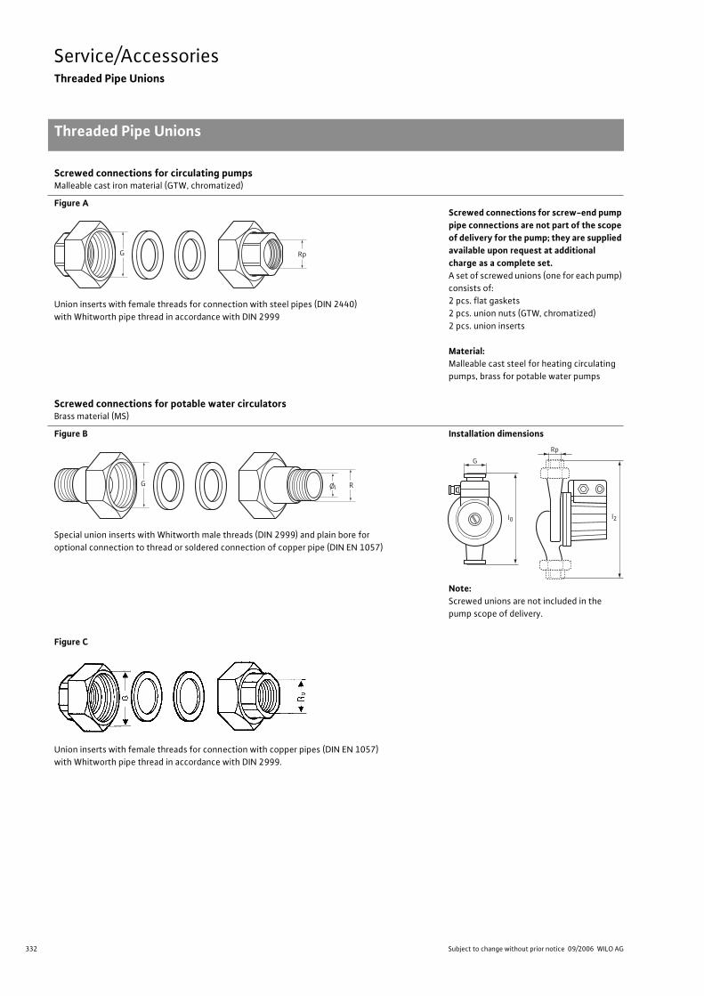
332 Subject to change without prior notice 09/2006 WILO AG
Service/AccessoriesThreaded Pipe Unions
Threaded Pipe Unions
Screwed connections for circulating pumpsMalleable cast iron material (GTW, chromatized)
Figure A
Union inserts with female threads for connection with steel pipes (DIN 2440)
with Whitworth pipe thread in accordance with DIN 2999
Screwed connections for screw-end pump pipe connections are not part of the scope of delivery for the pump; they are supplied available upon request at additional charge as a complete set.A set of screwed unions (one for each pump)
consists of:
2 pcs. flat gaskets
2 pcs. union nuts (GTW, chromatized)
2 pcs. union inserts
Material:Malleable cast steel for heating circulating
pumps, brass for potable water pumps
Screwed connections for potable water circulatorsBrass material (MS)
Figure B
Special union inserts with Whitworth male threads (DIN 2999) and plain bore for
optional connection to thread or soldered connection of copper pipe (DIN EN 1057)
Installation dimensions
Note:Screwed unions are not included in the
pump scope of delivery.
Figure C
Union inserts with female threads for connection with copper pipes (DIN EN 1057)
with Whitworth pipe thread in accordance with DIN 2999.
G Rp
G RØi
G
Rp
l0 l2
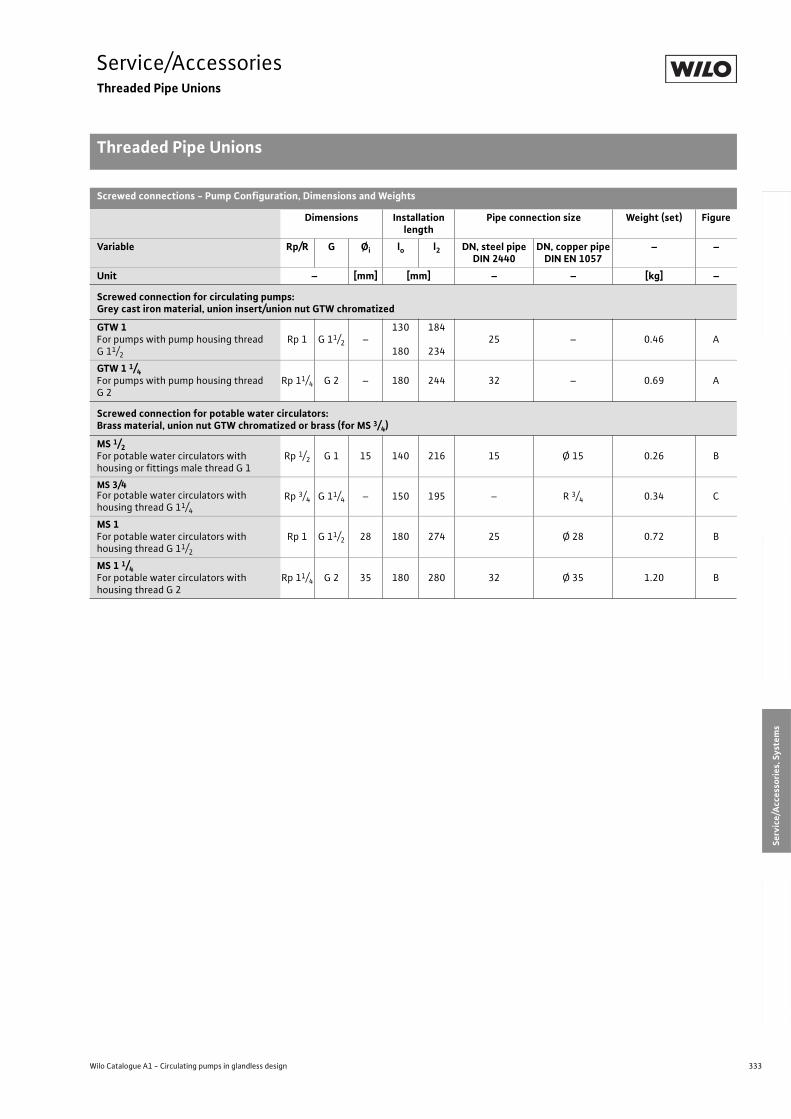
333
Service/AccessoriesThreaded Pipe Unions
Threaded Pipe Unions
Wilo Catalogue A1 - Circulating pumps in glandless design
Hea
tin
g, A
ir-c
on
dit
ion
ing
, C
oo
ling
Po
tab
le w
ater
cir
cula
tio
nSo
lar
ther
mal
Serv
ice/
Acc
esso
ries
, Sys
tem
sSw
itch
gea
rs a
nd
Co
ntr
ol
Dev
ices
P
um
p M
anag
emen
t S y
stem
s
Screwed connections - Pump Configuration, Dimensions and Weights
Dimensions Installation length
Pipe connection size Weight (set) Figure
Variable Rp/R G Øi lo l2 DN, steel pipeDIN 2440
DN, copper pipeDIN EN 1057
– –
Unit – [mm] [mm] – – [kg] –
Screwed connection for circulating pumps:Grey cast iron material, union insert/union nut GTW chromatized
GTW 1For pumps with pump housing thread G 11/2
Rp 1 G 11/2 –130
180
184
23425 – 0.46 A
GTW 1 1/4For pumps with pump housing thread G 2
Rp 11/4 G 2 – 180 244 32 – 0.69 A
Screwed connection for potable water circulators:Brass material, union nut GTW chromatized or brass (for MS 3/4)
MS 1/2For potable water circulators with housing or fittings male thread G 1
Rp 1/2 G 1 15 140 216 15 Ø 15 0.26 B
MS 3/4For potable water circulators with housing thread G 11/4
Rp 3/4 G 11/4 – 150 195 – R 3/4 0.34 C
MS 1 For potable water circulators with housing thread G 11/2
Rp 1 G 11/2 28 180 274 25 Ø 28 0.72 B
MS 1 1/4For potable water circulators with housing thread G 2
Rp 11/4 G 2 35 180 280 32 Ø 35 1.20 B
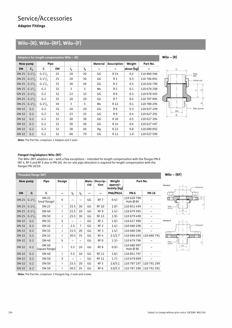
334 Subject to change without prior notice 09/2006 WILO AG
Service/AccessoriesAdapter Fittings
Wilo-(R), Wilo-(RF), Wilo-(F)
Adapters for length compensation Wilo – (R) Wilo – (R)
New pump Pipe Material Description Weight Part No.
DN C1 C DN I1 I2 – – about [kg] –
DN 25 G 11/2 G 11/2 25 18 20 GG R 24 0.2 110 880 596
DN 25 G 11/2 G 11/2 25 28 30 GG R 1 0.3 110 786 891
DN 25 G 11/2 G 11/2 25 38 40 GG R 2 0.5 110 626 790
DN 25 G 11/2 G 2 32 3 5 Ms R 5 0.1 110 678 298
DN 25 G 11/2 G 2 32 13 15 GG R 6 0.3 110 678 493
DN 25 G 11/2 G 2 32 18 20 GG R 7 0.4 110 787 094
DN 25 G 11/2 G 21/4 40 3 5 Ms R 12 0.1 110 788 294
DN 32 G 2 G 2 32 18 20 GG R 8 0.3 110 627 199
DN 32 G 2 G 2 32 23 25 GG R 9 0.4 110 627 291
DN 32 G 2 G 2 32 28 30 GG R 10 0.5 110 627 394
DN 32 G 2 G 2 32 38 40 GG R 14 0.6 110 627 497
DN 32 G 2 G 2 32 38 40 Rg R 22 0.8 110 680 092
DN 32 G 2 G 2 32 68 70 GG R 11 1.0 110 627 590
Note: The Part No. comprises: 1 Adapter and 2 seals
Flanged ring/adapters Wilo-(RF)The Wilo-(RF) adapters are - with a few exceptions - intended for length compensation with the flanges PN 6 (RF 4, RF 5 and RF 6 also in PN 16). An on-site pipe alteration is required for length compensation with the flanges PN 10/16.
Threaded flange (RF) Wilo – (RF)
New pump Pipe Design Mate-rial
Descrip-tion
Weight approxi-
mately [kg]
Part No.
DN G C – I1 I2 – – PN6/PN16 PN 6 PN 16
DN 25 G 11/2DN 25
(oval flange)II – – GG RF 7 0.4/-
110 628 790Hole Ø 80
–
DN 25 G 11/2 DN 25 I 25.5 30 GG RF 10 1.0/- 110 851 499 –
DN 25 G 11/2 DN 40 I 15.5 20 GG RF 9 1.4/- 110 679 395 –
DN 25 G 11/2 DN 50 I 25.5 30 GG RF 13 1.9/- 110 679 498 –
DN 32 G 2 DN 32 II – – GG RF 1 1.0/- 110 627 990 –
DN 32 G 2 DN 32 I 2.5 7 GG RF 2 1.4/- 110 680 298 –
DN 32 G 2 DN 32 I 15.5 20 GG RF 3 1.4/- 110 680 596 –
DN 32 G 2 DN 32 I 30.5 35 GG RF 4 2.5/2.7 110 680 699 110 680 791
DN 32 G 2 DN 40 II – – GG RF 0 1.3/- 110 679 796 –
DN 32 G 2DN 40
(square flange)I 5.5 10 GG RF 8 0.9/-
110 680 997Hole Ø 90
–
DN 32 G 2 DN 40 I 5.5 10 GG RF 12 1.6/- 110 851 797 –
DN 32 G 2 DN 50 II – – GG RF 11 1.7/- 110 679 899 –
DN 32 G 2 DN 50 I 15.5 20 GG RF 5 2.8/3.1 110 787 197 110 791 299
DN 32 G 2 DN 50 I 30.5 35 GG RF 6 3.0/3.3 110 787 290 110 791 391
Note: The Part No. comprises: 1 Flanged ring, 2 seals and screws
G
l 1
C
l 2l 0
DNNew pump
PipeDN
Union nut
C1
C
l 0
DN
Newpump
C1
l 1
C
l 2l 0
DN
Newpump
Pipework
Pipework
Version II
Version I
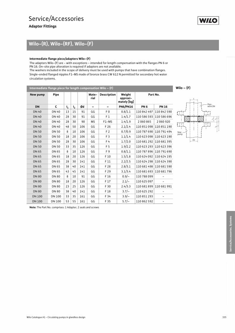
335
Service/AccessoriesAdapter Fittings
Wilo-(R), Wilo-(RF), Wilo-(F)
Wilo Catalogue A1 - Circulating pumps in glandless design
Hea
tin
g, A
ir-c
on
dit
ion
ing
, C
oo
ling
Po
tab
le w
ater
cir
cula
tio
nSo
lar
ther
mal
Serv
ice/
Acc
esso
ries
, Sys
tem
sSw
itch
gea
rs a
nd
Co
ntr
ol
Dev
ices
P
um
p M
anag
emen
t S y
stem
s
Intermediate flange piece/adapters Wilo–(F)The adapters Wilo-(F) are - with exceptions - intended for length compensation with the flanges PN 6 or PN 16. On-site pipe alteration is required if adapters are not available.The washers included in the scope of delivery must be used with pumps that have combination flanges.
Single-ended flanged nipples F1-MS made of bronze brass CW 612 N permitted for secondary hot water
circulation systems.
Intermediate flange piece for length compensation Wilo – (F) Wilo – (F)
New pump Pipe Mate-rial
Description Weight approxi-
mately [kg]
Part No.
DN C I1 I2 Ød – – PN6/PN16 PN 6 PN 16
DN 40 DN 40 13 15 91 GG F 0 0.8/1.1 110 842 497 110 842 590
DN 40 DN 40 28 30 91 GG F 1 1.4/1.7 110 586 593 110 586 696
DN 40 DN 40 28 30 90 MS F1-MS 1.4/1.9 2 060 865 2 060 920
DN 40 DN 40 48 50 106 GG F 26 2.1/2.4 110 851 098 110 851 190
DN 50 DN 50 8 10 106 GG F 2 0.7/0.9 110 787 690 110 791 494
DN 50 DN 50 18 20 106 GG F 3 1.1/1.4 110 623 098 110 623 190
DN 50 DN 50 28 30 106 GG F 4 1.7/2.0 110 681 292 110 681 395
DN 50 DN 50 33 35 126 GG F 5 1.9/2.2 110 623 293 110 623 396
DN 65 DN 65 8 10 126 GG F 9 0.8/1.1 110 787 896 110 791 690
DN 65 DN 65 18 20 126 GG F 10 1.5/1.8 110 624 092 110 624 195
DN 65 DN 65 28 30 141 GG F 11 2.2/2.5 110 624 298 110 624 390
DN 65 DN 65 38 40 141 GG F 28 2.8/3.1 110 681 498 110 681 590
DN 65 DN 65 43 45 141 GG F 29 3.1/3.4 110 681 693 110 681 796
DN 80 DN 80 8 10 91 GG F 16 0.9/– 110 788 099 -
DN 80 DN 80 18 20 126 GG F 17 2.1/– 110 625 097 -
DN 80 DN 80 23 25 126 GG F 30 2.4/3.3 110 681 899 110 681 991
DN 80 DN 80 38 40 141 GG F 18 3.7/– 110 625 292 -
DN 100 DN 100 33 35 161 GG F 34 3.9/– 110 851 293 -
DN 100 DN 100 53 55 161 GG F 35 5.7/– 110 862 592 -
Note: The Part No. comprises: 1 Adapter, 2 seals and screws
l 1
C
l 2l 0
DN
Newpump
Pipe-work DN
l 1
C
l 2l 0
DN
Newpump
Pipe-work DN
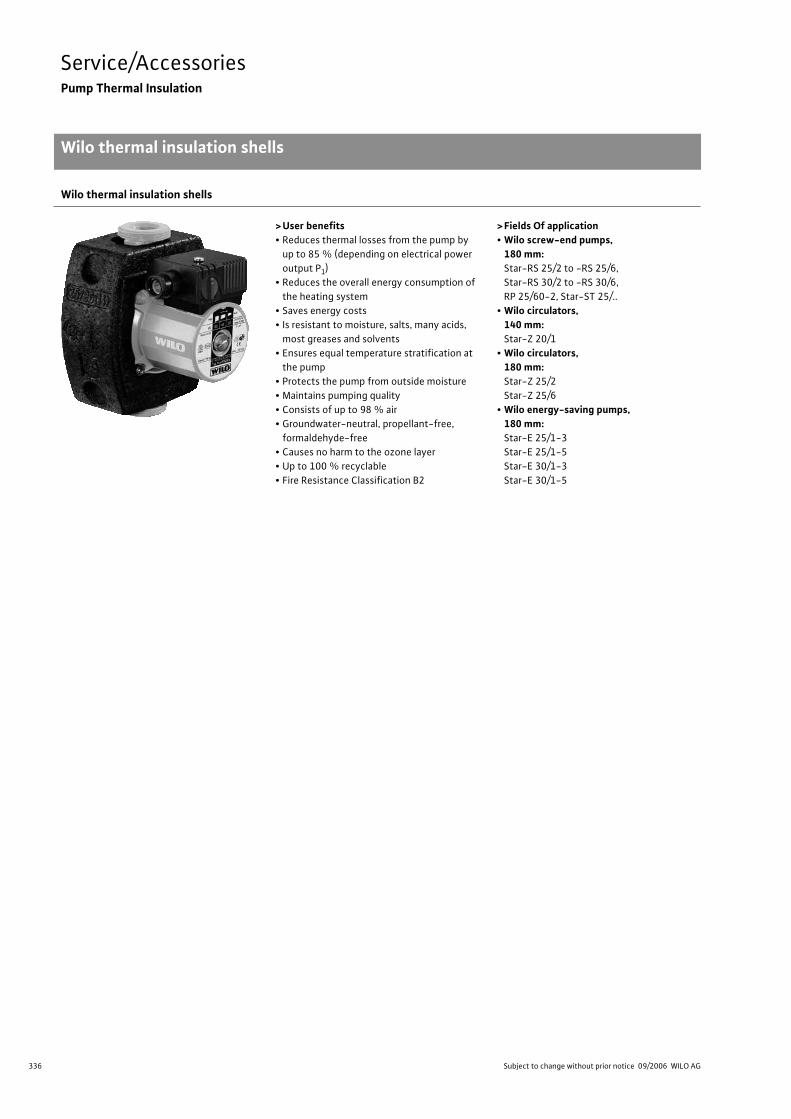
336 Subject to change without prior notice 09/2006 WILO AG
Service/AccessoriesPump Thermal Insulation
Wilo thermal insulation shells
Wilo thermal insulation shells
> User benefits• Reduces thermal losses from the pump by
up to 85 % (depending on electrical power
output P1)
• Reduces the overall energy consumption of
the heating system
• Saves energy costs
• Is resistant to moisture, salts, many acids,
most greases and solvents
• Ensures equal temperature stratification at
the pump
• Protects the pump from outside moisture
• Maintains pumping quality
• Consists of up to 98 % air
• Groundwater-neutral, propellant-free,
formaldehyde-free
• Causes no harm to the ozone layer
• Up to 100 % recyclable
• Fire Resistance Classification B2
> Fields Of application• Wilo screw-end pumps,
180 mm:Star-RS 25/2 to -RS 25/6,
Star-RS 30/2 to -RS 30/6,
RP 25/60-2, Star-ST 25/..
• Wilo circulators, 140 mm:Star-Z 20/1
• Wilo circulators, 180 mm:Star-Z 25/2
Star-Z 25/6
• Wilo energy-saving pumps, 180 mm:Star-E 25/1-3
Star-E 25/1-5
Star-E 30/1-3
Star-E 30/1-5
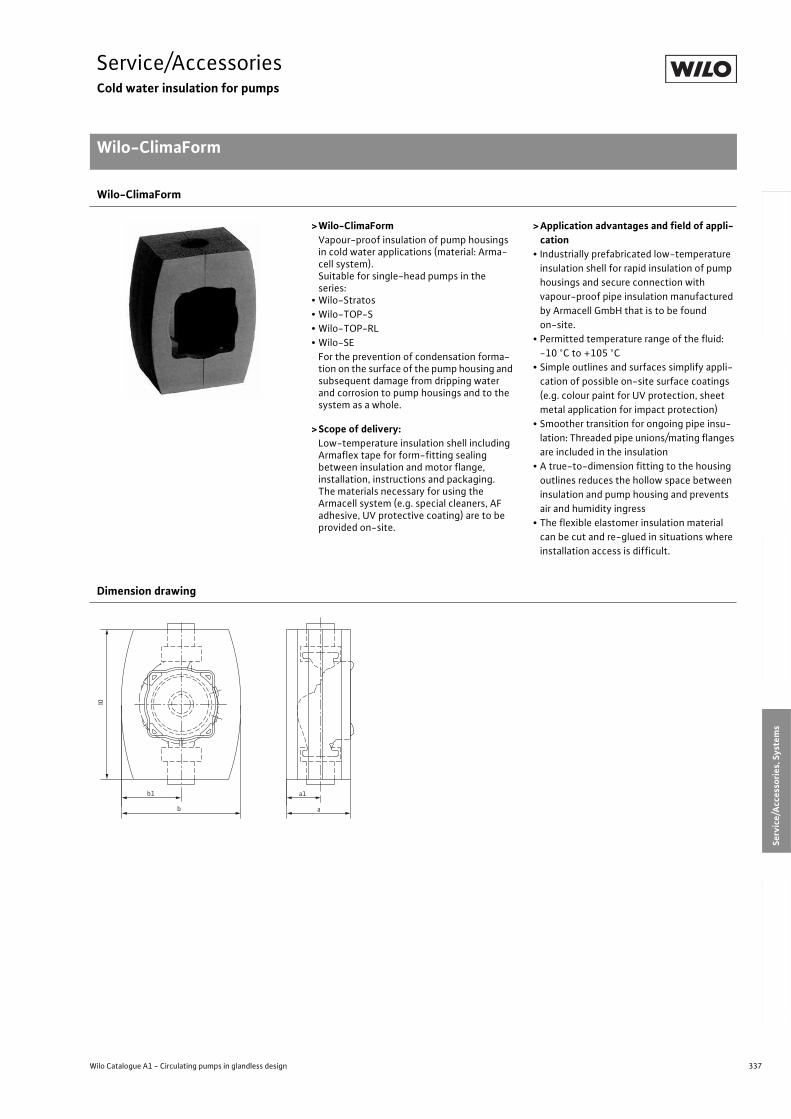
337
Service/AccessoriesCold water insulation for pumps
Wilo-ClimaForm
Wilo Catalogue A1 - Circulating pumps in glandless design
Hea
tin
g, A
ir-c
on
dit
ion
ing
, C
oo
ling
Po
tab
le w
ater
cir
cula
tio
nSo
lar
ther
mal
Serv
ice/
Acc
esso
ries
, Sys
tem
sSw
itch
gea
rs a
nd
Co
ntr
ol
Dev
ices
P
um
p M
anag
emen
t S y
stem
s
Wilo-ClimaForm
>Wilo-ClimaFormVapour-proof insulation of pump housings in cold water applications (material: Arma-cell system). Suitable for single-head pumps in the series:
• Wilo-Stratos
• Wilo-TOP-S
• Wilo-TOP-RL
• Wilo-SE
For the prevention of condensation forma-tion on the surface of the pump housing and subsequent damage from dripping water and corrosion to pump housings and to the system as a whole.
>Scope of delivery:Low-temperature insulation shell including Armaflex tape for form-fitting sealing between insulation and motor flange, installation, instructions and packaging. The materials necessary for using the Armacell system (e.g. special cleaners, AF adhesive, UV protective coating) are to be provided on-site.
>Application advantages and field of appli-cation
• Industrially prefabricated low-temperature
insulation shell for rapid insulation of pump
housings and secure connection with
vapour-proof pipe insulation manufactured
by Armacell GmbH that is to be found
on-site.
• Permitted temperature range of the fluid:
-10 °C to +105 °C
• Simple outlines and surfaces simplify appli-
cation of possible on-site surface coatings
(e.g. colour paint for UV protection, sheet
metal application for impact protection)
• Smoother transition for ongoing pipe insu-
lation: Threaded pipe unions/mating flanges
are included in the insulation
• A true-to-dimension fitting to the housing
outlines reduces the hollow space between
insulation and pump housing and prevents
air and humidity ingress
• The flexible elastomer insulation material
can be cut and re-glued in situations where
installation access is difficult.
Dimension drawing
b1
l0
b
a1
a
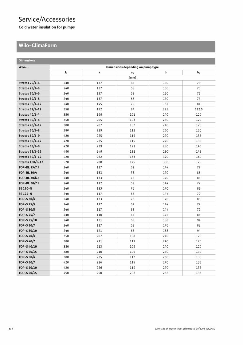
338 Subject to change without prior notice 09/2006 WILO AG
Service/AccessoriesCold water insulation for pumps
Wilo-ClimaForm
Dimensions
Wilo-... Dimensions depending on pump type
l0 a a1 b b1
[mm]
Stratos 25/1-6 240 137 68 150 75
Stratos 25/1-8 240 137 68 150 75
Stratos 30/1-6 240 137 68 150 75
Stratos 30/1-8 240 137 68 150 75
Stratos 30/1-12 240 145 75 162 81
Stratos 32/1-12 350 192 97 225 112.5
Stratos 40/1-4 350 199 101 240 120
Stratos 40/1-8 350 205 103 240 120
Stratos 40/1-12 380 207 107 240 120
Stratos 50/1-8 380 219 112 260 130
Stratos 50/1-9 420 225 115 270 135
Stratos 50/1-12 420 225 115 270 135
Stratos 65/1-9 420 239 121 280 140
Stratos 65/1-12 490 249 132 290 145
Stratos 80/1-12 520 262 133 320 160
Stratos 100/1-12 520 280 145 350 175
TOP-RL 25/7.5 240 117 62 144 72
TOP-RL 30/4 240 133 76 170 85
TOP-RL 30/6.5 240 133 76 170 85
TOP-RL 30/7.5 240 117 62 144 72
SE 110-N 240 133 76 170 85
SE 125-N 240 117 62 144 72
TOP-S 30/4 240 133 76 170 85
TOP-S 25/5 240 117 62 144 72
TOP-S 30/5 240 117 62 144 72
TOP-S 25/7 240 110 62 176 88
TOP-S 25/10 240 121 68 188 94
TOP-S 30/7 240 117 68 176 88
TOP-S 30/10 240 121 68 188 94
TOP-S 40/4 350 207 108 240 120
TOP-S 40/7 380 211 111 240 120
TOP-S 40/10 380 213 109 240 120
TOP-S 40/15 380 210 106 260 130
TOP-S 50/4 380 225 117 260 130
TOP-S 50/7 420 226 115 270 135
TOP-S 50/10 420 226 119 270 135
TOP-S 50/15 490 250 202 266 133
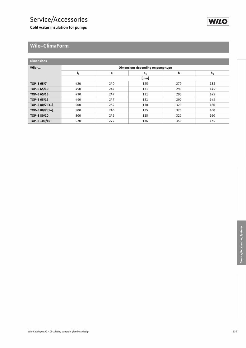
339
Service/AccessoriesCold water insulation for pumps
Wilo-ClimaForm
Wilo Catalogue A1 - Circulating pumps in glandless design
Hea
tin
g, A
ir-c
on
dit
ion
ing
, C
oo
ling
Po
tab
le w
ater
cir
cula
tio
nSo
lar
ther
mal
Serv
ice/
Acc
esso
ries
, Sys
tem
sSw
itch
gea
rs a
nd
Co
ntr
ol
Dev
ices
P
um
p M
anag
emen
t S y
stem
s
TOP-S 65/7 420 240 125 270 135
TOP-S 65/10 490 247 131 290 145
TOP-S 65/13 490 247 131 290 145
TOP-S 65/15 490 247 131 290 145
TOP-S 80/7 (3~) 500 252 130 320 160
TOP-S 80/7 (1~) 500 246 125 320 160
TOP-S 80/10 500 246 125 320 160
TOP-S 100/10 520 272 136 350 175
Dimensions
Wilo-... Dimensions depending on pump type
l0 a a1 b b1
[mm]
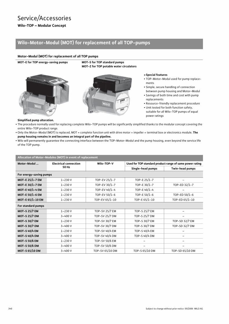
340 Subject to change without prior notice 09/2006 WILO AG
Service/AccessoriesWilo-TOP – Modular Concept
Wilo-Motor-Modul (MOT) for replacement of all TOP-pumps
Simplified pump alteration. • The procedure normally used for replacing complete Wilo-TOP pumps will be significantly simplified thanks to the modular concept covering the
entire Wilo-TOP product range.
• Only the Motor-Modul (MOT) is replaced, MOT = complete function unit with drive motor + impeller + terminal box or electronics module. Thepump housing remains in and becomes an integral part of the pipeline.
• Wilo will permanently guarantee the connecting interface between the TOP-Motor-Modul and the pump housing, even beyond the service life
of the TOP pump.
Motor-Modul (MOT) for replacement of all TOP pumps
MOT-E for TOP energy-saving pumps MOT-S for TOP standard pumpsMOT-Z for TOP potable water circulators
> Special features• TOP-Motor-Modul used for pump replace-
ments
• Simple, secure handling of connection
between pump housing and Motor-Modul
• Savings of both time and cost with pump
replacements
• Resource-friendly replacement procedure
• Unit tested for both function safety,
suitable for all Wilo-TOP pumps of equal
power ratings
Allocation of Motor-Modules (MOT) in event of replacement
Motor-Modul … Electrical connection50 Hz
Wilo-TOP-V Used for TOP standard product range of same power rating
Single-head pumps Twin-head pumps
For energy-saving pumps
MOT-E 25/1-7 EM 1~230 V TOP-EV 25/1-7 TOP-E 25/1-7 –
MOT-E 30/1-7 EM 1~230 V TOP-EV 30/1-7 TOP-E 30/1-7 TOP-ED 32/1-7
MOT-E 40/1-4 EM 1~230 V TOP-EV 40/1-4 TOP-E 40/1-4 –
MOT-E 50/1-6 EM 1~230 V TOP-EV 50/1-6 TOP-E 50/1-6 TOP-ED 50/1-6
MOT-E 65/1-10 EM 1~230 V TOP-EV 65/1-10 TOP-E 65/1-10 TOP-ED 65/1-10
For standard pumps
MOT-S 25/7 EM 1~230 V TOP-SV 25/7 EM TOP-S 25/7 EM –
MOT-S 25/7 DM 3~400 V TOP-SV 25/7 DM TOP-S 25/7 DM –
MOT-S 30/7 EM 1~230 V TOP-SV 30/7 EM TOP-S 30/7 EM TOP-SD 32/7 EM
MOT-S 30/7 DM 3~400 V TOP-SV 30/7 DM TOP-S 30/7 DM TOP-SD 32/7 DM
MOT-S 40/4 EM 1~230 V TOP-SV 40/4 EM TOP-S 40/4 EM –
MOT-S 40/4 DM 3~400 V TOP-SV 40/4 DM TOP-S 40/4 DM –
MOT-S 50/6 EM 1~230 V TOP-SV 50/6 EM – –
MOT-S 50/6 DM 3~400 V TOP-SV 50/6 DM – –
MOT-S 65/10 DM 3~400 V TOP-SV 65/10 DM TOP-S 65/10 DM TOP-SD 65/10 DM
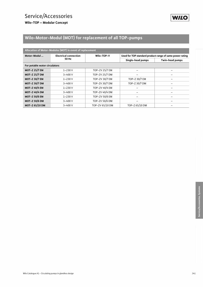
341
Service/AccessoriesWilo-TOP – Modular Concept
Wilo-Motor-Modul (MOT) for replacement of all TOP-pumps
Wilo Catalogue A1 - Circulating pumps in glandless design
Hea
tin
g, A
ir-c
on
dit
ion
ing
, C
oo
ling
Po
tab
le w
ater
cir
cula
tio
nSo
lar
ther
mal
Serv
ice/
Acc
esso
ries
, Sys
tem
sSw
itch
gea
rs a
nd
Co
ntr
ol
Dev
ices
P
um
p M
anag
emen
t S y
stem
s
For potable water circulators
MOT-Z 25/7 EM 1~230 V TOP-ZV 25/7 EM – –
MOT-Z 25/7 DM 3~400 V TOP-ZV 25/7 DM – –
MOT-Z 30/7 EM 1~230 V TOP-ZV 30/7 EM TOP-Z 30/7 EM –
MOT-Z 30/7 DM 3~400 V TOP-ZV 30/7 DM TOP-Z 30/7 DM –
MOT-Z 40/4 EM 1~230 V TOP-ZV 40/4 EM – –
MOT-Z 40/4 DM 3~400 V TOP-ZV 40/4 DM – –
MOT-Z 50/6 EM 1~230 V TOP-ZV 50/6 EM – –
MOT-Z 50/6 DM 3~400 V TOP-ZV 50/6 DM – –
MOT-Z 65/10 DM 3~400 V TOP-ZV 65/10 DM TOP-Z 65/10 DM –
Allocation of Motor-Modules (MOT) in event of replacement
Motor-Modul … Electrical connection50 Hz
Wilo-TOP-V Used for TOP standard product range of same power rating
Single-head pumps Twin-head pumps
342 Subject to change without prior notice 09/2006 WILO AG
Service/AccessoriesWilo-TOP – Modular Concept
L
Wilo-TOP – Modular Concept
343
SystemsContents
Wilo Catalogue A1 - Circulating pumps in glandless design
Hea
tin
g, A
ir-c
on
dit
ion
ing
, C
oo
ling
Po
tab
le w
ater
cir
cula
tio
nSo
lar
ther
mal
Serv
ice/
Acc
esso
ries
, Sys
tem
sSw
itch
gea
rs a
nd
Co
ntr
ol
Dev
ices
P
um
p M
anag
emen
t S y
stem
s
Systems
System separation for floor heating Wilo-Safe-WS, Wilo-DrainLift Con 344
Series overview 344
Series description 345
Technical Data 347
Lifting unit for condensates Wilo-DrainLift Con 348
Series description 348
Technical Data, Pump Curve, Dimension Drawing 349
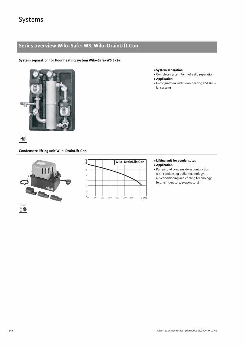
344 Subject to change without prior notice 09/2006 WILO AG
Systems
Series overview Wilo-Safe-WS, Wilo-DrainLift Con
System separation for floor heating system Wilo-Safe-WS 5-24
> System separation:• Complete system for hydraulic separation
> Application:• In conjunction with floor-heating and simi-
lar systems
Condensate lifting unit Wilo-DrainLift Con
> Lifting unit for condensates> Application:• Pumping of condensate in conjunction
with condensing boiler technology,
air-conditioning and cooling technology
(e.g. refrigerators, evaporators)
0 50 100 150 200 250 3000
1
2
3
4
5
H[m
]
Wilo-DrainLift Con
Q [l/h]
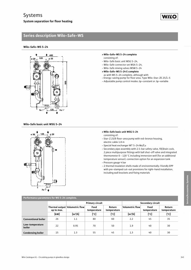
345
SystemsSystem separation for floor heating
Series description Wilo-Safe-WS
Wilo Catalogue A1 - Circulating pumps in glandless design
Hea
tin
g, A
ir-c
on
dit
ion
ing
, C
oo
ling
Po
tab
le w
ater
cir
cula
tio
nSo
lar
ther
mal
Serv
ice/
Acc
esso
ries
, Sys
tem
sSw
itch
gea
rs a
nd
Co
ntr
ol
Dev
ices
P
um
p M
anag
emen
t S y
stem
s
Wilo-Safe-WS 5-24
> Wilo-Safe-WS 5-24 complete consisting of:
- Wilo-Safe basic unit WSG 5-24,
- Wilo-Safe connector set WSA 5-24,
- Wilo-Safe mixing valves WSM 5-24
> Wilo-Safe-WS 5-24 E complete as with WS 5-24 complete, although with
- Energy-saving pump for floor area, Type Wilo-Star-ZE 25/1-5
- Adjustable pump control modes p-constant or p-variable
Wilo-Safe basic unit WSG 5-24
> Wilo-Safe basic unit WSG 5-24consisting of:
- Star-Z 25/6 floor-area pump with red-bronze housing,
electric cable 1.8 m
- Special heat exchanger WT 5-24 Ms/Cu
- Secondary pipe assembly with 2.5-bar safety valve, fill/drain cock,
2 piece multipurpose fittings with ball shut-off valve and integrated
thermometer 0 - 120 °C including immersion well (for an additional
temperature sensor), connection option for an expansion tank
- Pressure gauge 4 bar
- 2 thermal insulation shells made of environmentally-friendly EPP
with pre-stamped cut-out provisions for right-hand installation,
including wall brackets and fixing materials
Performance parameters for WS 5-24 complete.
Primary circuit Secondary circuit
Thermal output up to max.
Volumetric flow Feed temperature
Return temperature
Volumetric flow Feed temperature
Return temperature
[kW] [m3/h] [°C] [°C] [m3/h] [°C] [°C]
Conventional boiler 26 1.1 80 60 2,2 45 35
Low-temperature boiler
22 0.95 70 50 1,9 40 30
Condensing boiler 15 1.3 55 45 1,3 40 30
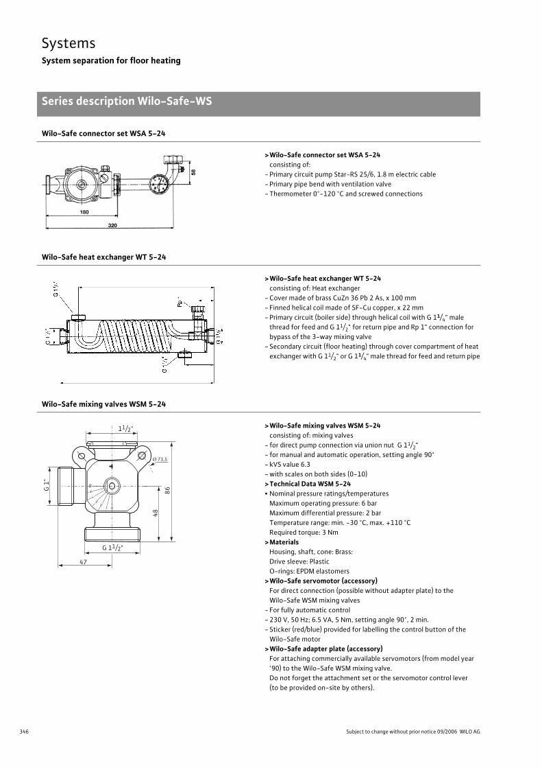
346 Subject to change without prior notice 09/2006 WILO AG
SystemsSystem separation for floor heating
Series description Wilo-Safe-WS
Wilo-Safe connector set WSA 5-24
>Wilo-Safe connector set WSA 5-24consisting of:
- Primary circuit pump Star-RS 25/6, 1.8 m electric cable
- Primary pipe bend with ventilation valve
- Thermometer 0°-120 °C and screwed connections
Wilo-Safe heat exchanger WT 5-24
>Wilo-Safe heat exchanger WT 5-24consisting of: Heat exchanger
- Cover made of brass CuZn 36 Pb 2 As, x 100 mm
- Finned helical coil made of SF-Cu copper, x 22 mm
- Primary circuit (boiler side) through helical coil with G 11/4" male
thread for feed and G 11/2" for return pipe and Rp 1" connection for
bypass of the 3-way mixing valve
- Secondary circuit (floor heating) through cover compartment of heat
exchanger with G 11/2" or G 11/4" male thread for feed and return pipe
Wilo-Safe mixing valves WSM 5-24
>Wilo-Safe mixing valves WSM 5-24consisting of: mixing valves
- for direct pump connection via union nut G 11/2"
- for manual and automatic operation, setting angle 90°
- kVS value 6.3
- with scales on both sides (0-10)
>Technical Data WSM 5-24• Nominal pressure ratings/temperatures
Maximum operating pressure: 6 bar
Maximum differential pressure: 2 bar
Temperature range: min. -30 °C, max. +110 °C
Required torque: 3 Nm
>MaterialsHousing, shaft, cone: Brass:
Drive sleeve: Plastic
O-rings: EPDM elastomers
>Wilo-Safe servomotor (accessory)For direct connection (possible without adapter plate) to the
Wilo-Safe WSM mixing valves
- For fully automatic control
- 230 V, 50 Hz; 6.5 VA, 5 Nm, setting angle 90°, 2 min.
- Sticker (red/blue) provided for labelling the control button of the
Wilo-Safe motor
>Wilo-Safe adapter plate (accessory)For attaching commercially available servomotors (from model year
'90) to the Wilo-Safe WSM mixing valve.
Do not forget the attachment set or the servomotor control lever
(to be provided on-site by others).
11/2"
G 11/2"
47
86
Ø 73,5
48
G 1
"
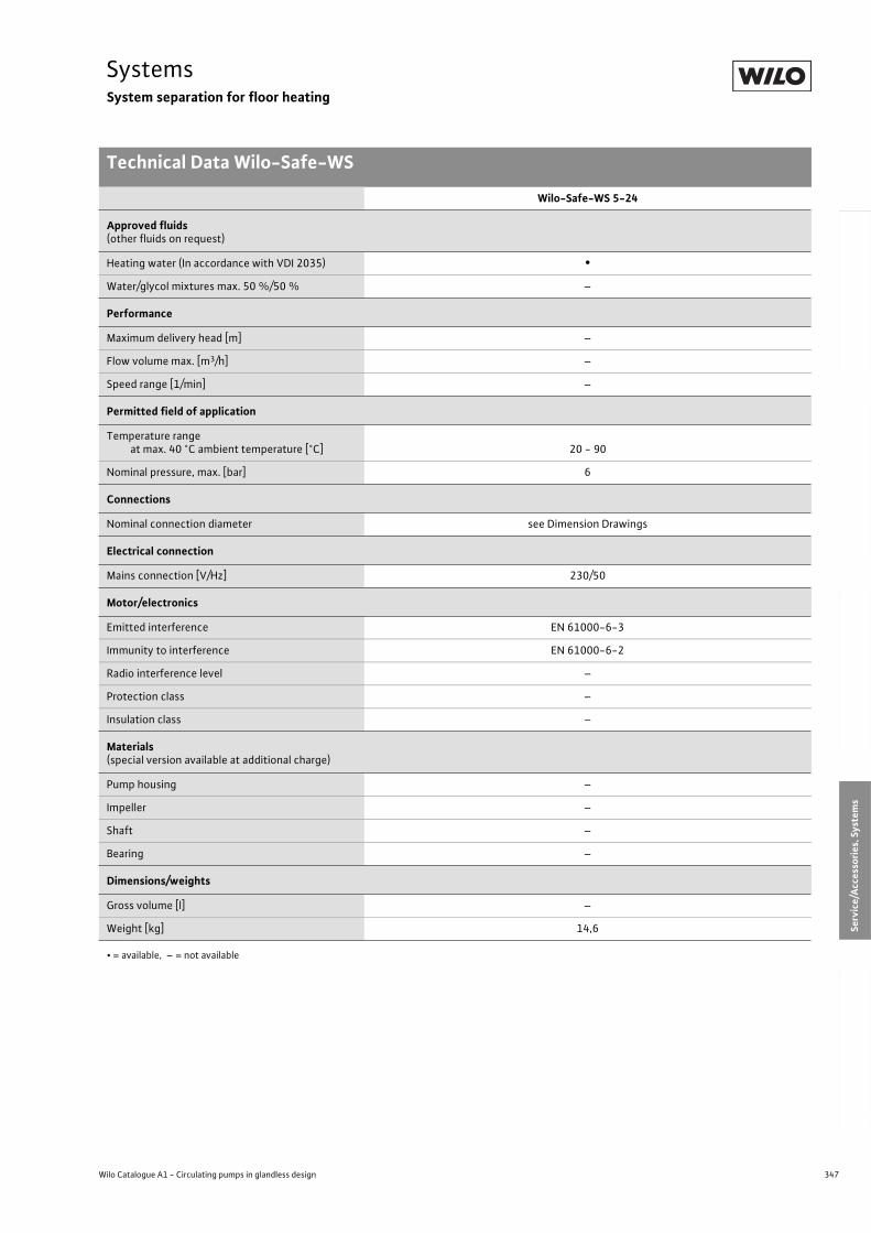
347
SystemsSystem separation for floor heating
Technical Data Wilo-Safe-WS
Wilo Catalogue A1 - Circulating pumps in glandless design
Hea
tin
g, A
ir-c
on
dit
ion
ing
, C
oo
ling
Po
tab
le w
ater
cir
cula
tio
nSo
lar
ther
mal
Serv
ice/
Acc
esso
ries
, Sys
tem
sSw
itch
gea
rs a
nd
Co
ntr
ol
Dev
ices
P
um
p M
anag
emen
t S y
stem
s
Wilo-Safe-WS 5-24
Approved fluids(other fluids on request)
Heating water (In accordance with VDI 2035) •
Water/glycol mixtures max. 50 %/50 % –
Performance
Maximum delivery head [m] –
Flow volume max. [m3/h] –
Speed range [1/min] –
Permitted field of application
Temperature rangeat max. 40 °C ambient temperature [°C] 20 - 90
Nominal pressure, max. [bar] 6
Connections
Nominal connection diameter see Dimension Drawings
Electrical connection
Mains connection [V/Hz] 230/50
Motor/electronics
Emitted interference EN 61000-6-3
Immunity to interference EN 61000-6-2
Radio interference level –
Protection class –
Insulation class –
Materials(special version available at additional charge)
Pump housing –
Impeller –
Shaft –
Bearing –
Dimensions/weights
Gross volume [l] –
Weight [kg] 14,6
• = available, – = not available

348 Subject to change without prior notice 09/2006 WILO AG
SystemsLifting unit for condensates
Series description Wilo-DrainLift Con
Wilo-DrainLift ConAutomatic lifting unit for condensates with feed adapters (accessory)
Type keyExample: Wilo-DrainLift ConCon Condensate
ApplicationThe condensate lifting unit must be used if disposal is not possible via
natural gravity flow, or if the installation location is below the back-
flow level. It has been designed for installation in condensing boilers
that generate aggressive condensate according to the specifications
of “Arbeitsblatt A 251” as distributed by the ATV (German Associa-
tion for Water, Wastewater and Waste). Because of the materials
used in the manufacture of the plant, condensate with a pH value
of up to 2.4 can be conveyed without any problems. For oil-fired or
gas-fired boilers with an output > 200 kW, the lifting unit must be
installed downline of a neutralisation system. The condensate lifting
unit can also be used in the air-conditioning and cooling systems
where condensate is produced, for example refrigerators and freez-
ers, evaporators, and refrigerated display cases.
The plant can be installed in free-standing form or vertically wall-
mounted with two fastening holes. The positioning of the motor unit
on the tank is reversible, allowing a variable inlet and outlet.
Construction2 inlets in the lid (19 or 2 mm). Hose connection on discharge end,
DN 10 mm with built-in check valve.
Scope of deliveryFully-assembled lifting unit with standard series alarm contact for
connection to condensing boiler or alarm switchgear. Including hose
connection with integrated non-return valve, 5 m hose for delivery
side, 1 m alarm cable and 2 m power cable with grounding plug and
wall-mounting materials, installation and operating instructions.
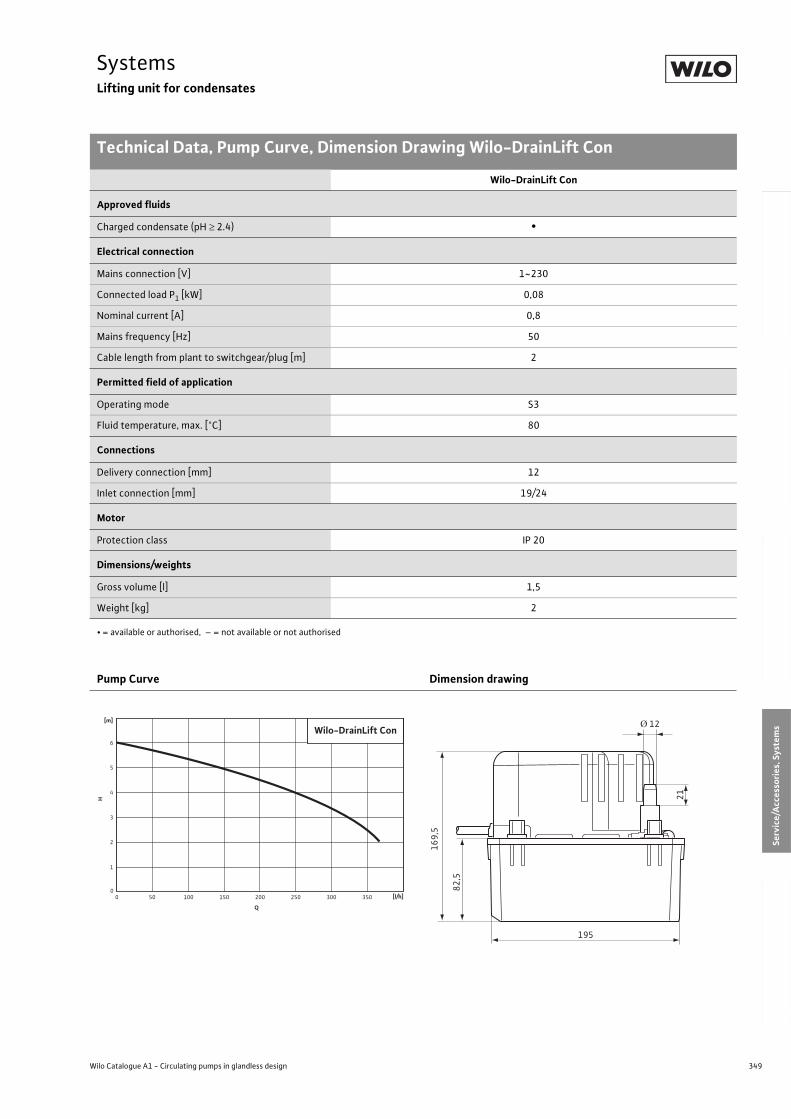
349
SystemsLifting unit for condensates
Technical Data, Pump Curve, Dimension Drawing Wilo-DrainLift Con
Wilo Catalogue A1 - Circulating pumps in glandless design
Hea
tin
g, A
ir-c
on
dit
ion
ing
, C
oo
ling
Po
tab
le w
ater
cir
cula
tio
nSo
lar
ther
mal
Serv
ice/
Acc
esso
ries
, Sys
tem
sSw
itch
gea
rs a
nd
Co
ntr
ol
Dev
ices
P
um
p M
anag
emen
t S y
stem
s
Wilo-DrainLift Con
Approved fluids
Charged condensate (pH 2.4) •
Electrical connection
Mains connection [V] 1~230
Connected load P1 [kW] 0,08
Nominal current [A] 0,8
Mains frequency [Hz] 50
Cable length from plant to switchgear/plug [m] 2
Permitted field of application
Operating mode S3
Fluid temperature, max. [°C] 80
Connections
Delivery connection [mm] 12
Inlet connection [mm] 19/24
Motor
Protection class IP 20
Dimensions/weights
Gross volume [l] 1,5
Weight [kg] 2
• = available or authorised, – = not available or not authorised
Pump Curve Dimension drawing
[l/h]0 50 100 150 200 250 300 350
H
0
2
4
3
5
6
1
Q
Wilo-DrainLift Con [m]
21
Ø 12
195
169,
5
82,5
350 Subject to change without prior notice 09/2006 WILO AG
SystemsLifting unit for condensates
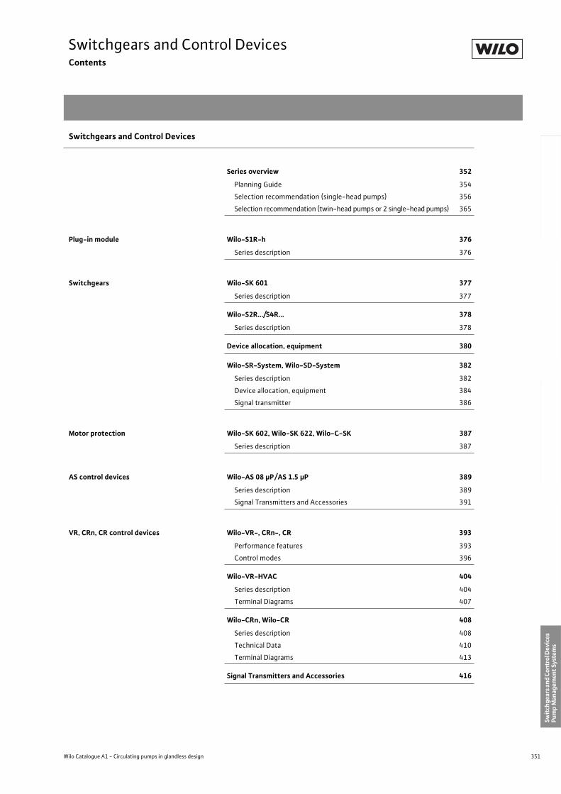
351
Switchgears and Control DevicesContents
Wilo Catalogue A1 - Circulating pumps in glandless design
Hea
tin
g, A
ir-c
on
dit
ion
ing
, C
oo
ling
Po
tab
le w
ater
cir
cula
tio
nSo
lar
ther
mal
Serv
ice/
Acc
esso
ries
, Sys
tem
sSw
itch
gear
s an
d C
ontr
ol D
evic
es
Pum
p M
anag
emen
t Sy
stem
s
Switchgears and Control Devices
Series overview 352
Planning Guide 354
Selection recommendation (single-head pumps) 356
Selection recommendation (twin-head pumps or 2 single-head pumps) 365
Plug-in module Wilo-S1R-h 376
Series description 376
Switchgears Wilo-SK 601 377
Series description 377
Wilo-S2R.../S4R… 378
Series description 378
Device allocation, equipment 380
Wilo-SR-System, Wilo-SD-System 382
Series description 382
Device allocation, equipment 384
Signal transmitter 386
Motor protection Wilo-SK 602, Wilo-SK 622, Wilo-C-SK 387
Series description 387
AS control devices Wilo-AS 08 µP/AS 1.5 µP 389
Series description 389
Signal Transmitters and Accessories 391
VR, CRn, CR control devices Wilo-VR-, CRn-, CR 393
Performance features 393
Control modes 396
Wilo-VR-HVAC 404
Series description 404
Terminal Diagrams 407
Wilo-CRn, Wilo-CR 408
Series description 408
Technical Data 410
Terminal Diagrams 413
Signal Transmitters and Accessories 416
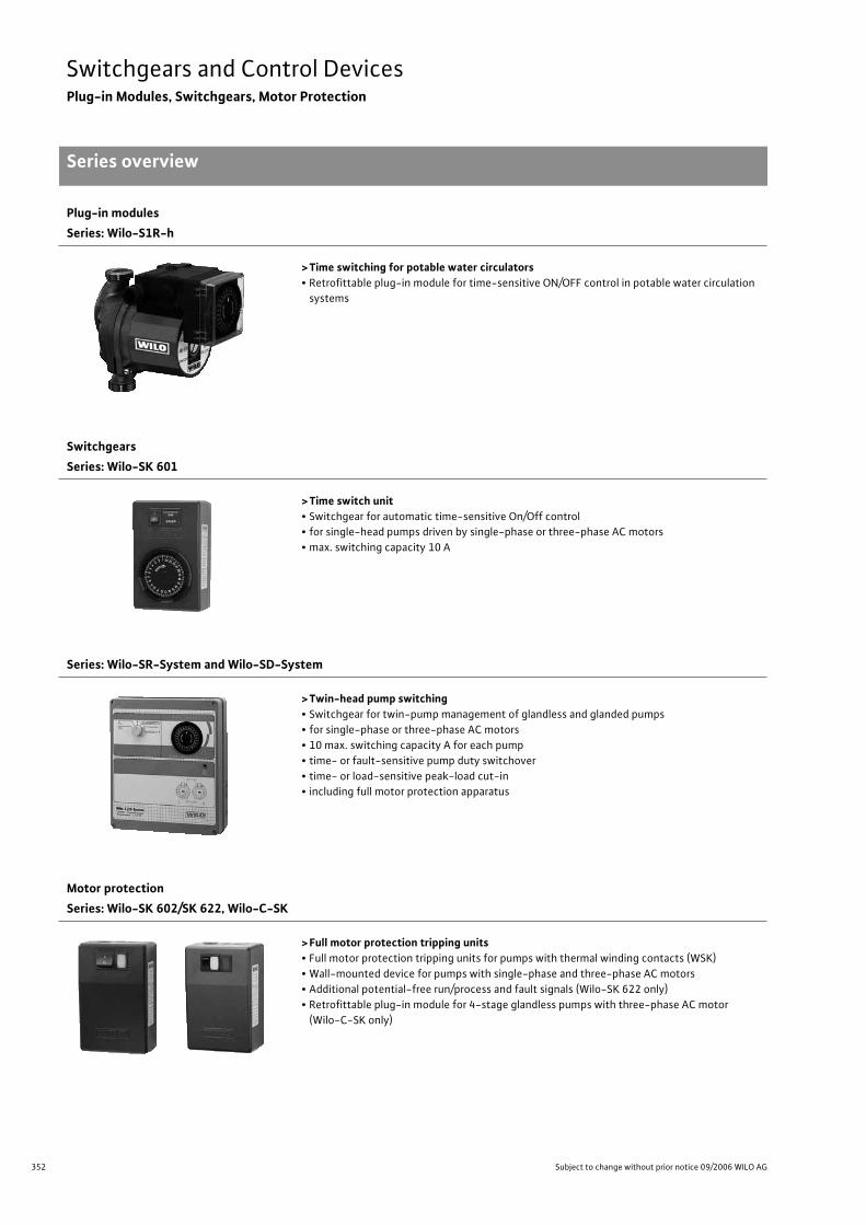
352 Subject to change without prior notice 09/2006 WILO AG
Switchgears and Control DevicesPlug-in Modules, Switchgears, Motor Protection
Series overview
Plug-in modules
Series: Wilo-S1R-h
> Time switching for potable water circulators• Retrofittable plug-in module for time-sensitive ON/OFF control in potable water circulation
systems
Switchgears
Series: Wilo-SK 601
> Time switch unit• Switchgear for automatic time-sensitive On/Off control
• for single-head pumps driven by single-phase or three-phase AC motors
• max. switching capacity 10 A
Series: Wilo-SR-System and Wilo-SD-System
> Twin-head pump switching• Switchgear for twin-pump management of glandless and glanded pumps
• for single-phase or three-phase AC motors
• 10 max. switching capacity A for each pump
• time- or fault-sensitive pump duty switchover
• time- or load-sensitive peak-load cut-in
• including full motor protection apparatus
Motor protection
Series: Wilo-SK 602/SK 622, Wilo-C-SK
> Full motor protection tripping units• Full motor protection tripping units for pumps with thermal winding contacts (WSK)
• Wall-mounted device for pumps with single-phase and three-phase AC motors
• Additional potential-free run/process and fault signals (Wilo-SK 622 only)
• Retrofittable plug-in module for 4-stage glandless pumps with three-phase AC motor
(Wilo-C-SK only)
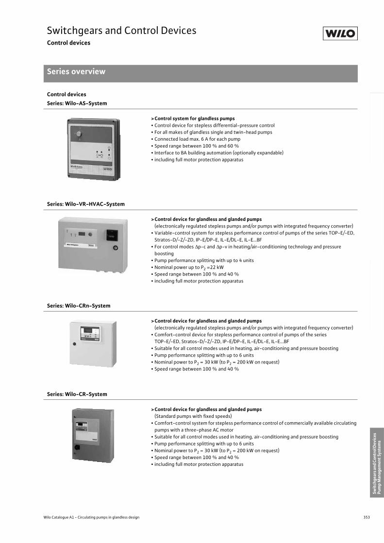
353
Switchgears and Control DevicesControl devices
Series overview
Wilo Catalogue A1 - Circulating pumps in glandless design
Hea
tin
g, A
ir-c
on
dit
ion
ing
, C
oo
ling
Po
tab
le w
ater
cir
cula
tio
nSo
lar
ther
mal
Serv
ice/
Acc
esso
ries
, Sys
tem
sSw
itch
gear
s an
d C
ontr
ol D
evic
es
Pum
p M
anag
emen
t Sy
stem
s
Control devices
Series: Wilo-AS-System
>Control system for glandless pumps• Control device for stepless differential-pressure control
• For all makes of glandless single and twin-head pumps
• Connected load max. 6 A for each pump
• Speed range between 100 % and 60 %
• Interface to BA building automation (optionally expandable)
• including full motor protection apparatus
Series: Wilo-VR-HVAC-System
>Control device for glandless and glanded pumps(electronically regulated stepless pumps and/or pumps with integrated frequency converter)
• Variable-control system for stepless performance control of pumps of the series TOP-E/-ED,
Stratos-D/-Z/-ZD, IP-E/DP-E, IL-E/DL-E, IL-E…BF
• For control modes p-c and p-v in heating/air-conditioning technology and pressure
boosting
• Pump performance splitting with up to 4 units
• Nominal power up to P2 =22 kW
• Speed range between 100 % and 40 %
• including full motor protection apparatus
Series: Wilo-CRn-System
>Control device for glandless and glanded pumps(electronically regulated stepless pumps and/or pumps with integrated frequency converter)
• Comfort-control device for stepless performance control of pumps of the series
TOP-E/-ED, Stratos-D/-Z/-ZD, IP-E/DP-E, IL-E/DL-E, IL-E...BF
• Suitable for all control modes used in heating, air-conditioning and pressure boosting
• Pump performance splitting with up to 6 units
• Nominal power to P2 = 30 kW (to P2 = 200 kW on request)
• Speed range between 100 % and 40 %
Series: Wilo-CR-System
>Control device for glandless and glanded pumps (Standard pumps with fixed speeds)
• Comfort-control system for stepless performance control of commercially available circulating
pumps with a three-phase AC motor
• Suitable for all control modes used in heating, air-conditioning and pressure boosting
• Pump performance splitting with up to 6 units
• Nominal power to P2 = 30 kW (to P2 = 200 kW on request)
• Speed range between 100 % and 40 %
• including full motor protection apparatus
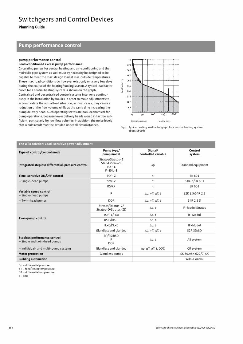
354 Subject to change without prior notice 09/2006 WILO AG
Switchgears and Control DevicesPlanning Guide
Pump performance control
pump performance controlLoad-conditioned excess pump performanceCirculating pumps for central heating and air-conditioning and the
hydraulic pipe system as well must by necessity be designed to be
capable to meet the max. design load at min. outside temperatures.
These max. load conditions do however exist only on a very few days
during the course of the heating/cooling season. A typical load factor
curve for a central heating system is shown on the graph.
Centralised and decentralised control systems intervene continu-
ously in the installation hydraulics in order to make adjustments to
accommodate the actual load situation; in most cases, they cause a
reduction of the flow volume while at the same time increasing the
pump delivery head. Such operating states are non-economical for
pump operations, because lower delivery heads would in fact be suf-
ficient, particularly for low flow volumes; in addition, the noise levels
that would result must be avoided under all circumstances.Fig.: Typical heating load factor graph for a central heating system:
about 5500 h
The Wilo solution: Load-sensitive power adjustment
Type of control/control modePump type/pump model
Signal/controlled variable
Controlsystem
Integrated stepless differential-pressure control
Stratos/Stratos-ZStar-E/Star-ZE
TOP-EIP-E/IL-E
p Standard equipment
Time-sensitive ON/OFF control TOP-Z t SK 601
– Single-head pumps Star-Z t S1R-h/SK 601
RS/RP t SK 601
Variable speed control– Single-head pumps
P p, +T, T, t S2R 2.5/S4R 2.5
– Twin-head pumps DOP p, +T, T, t S4R 2.5 D
Twin-pump control
Stratos/Stratos-Z/Stratos-D/Stratos-ZD
p, t IF-Modul Stratos
TOP-E/-ED p, t IF-Modul
IP-E/DP-E p, t
IL-E/DL-E p, t IF-Modul
Glandless and glanded p, +T, T, t S2R 3D/SD
Stepless performance control– Single and twin-head pumps
RP/RS/RSDP
DOPp, t AS system
– Individual- and multi-pump systems Glandless and glanded p, ±T, T, t, DDC CR system
Motor protection Glandless pumps SK 602/SK 622/C-SK
Building automation Wilo-Control
p = differential pressure ±T = feed/return temperature
T = differential temperature t = time
Operating range Heating days Lo
ad fa
ctor

355
Switchgears and Control DevicesPlanning Guide
Pump performance control
Wilo Catalogue A1 - Circulating pumps in glandless design
Hea
tin
g, A
ir-c
on
dit
ion
ing
, C
oo
ling
Po
tab
le w
ater
cir
cula
tio
nSo
lar
ther
mal
Serv
ice/
Acc
esso
ries
, Sys
tem
sSw
itch
gear
s an
d C
ontr
ol D
evic
es
Pum
p M
anag
emen
t Sy
stem
s
Need for controlThree main criteria, in line with the steady development of mechani-
cal equipment for building services and the growing sensibility
towards energy consumption, have led to the increased considera-
tion of controls for utilisation in conjunction with heating pumps.
1. Function optimisationAdjusting the pump capacity/heat flow to actual load demand, par-
ticularly to stabilise hydraulic conditions and to reduce circulating
losses.
2. Economic efficiencyReducing power consumption and operating costs, particularly in
partial- or low-load operation (i.e. in over 80 % of the overall
operating time).
3. Comfort and convenienceAvoiding system noise, in particular flow noise and noise in the ther-
mostatic valves that are due to excessive flow and thermostatic
radiator valves (TRV’s).
Power savings in relation to reducing CO2 emissions are in conjunc-
tion with environmental-protection considerations playing an ever
more important role. It is widely known that generating power from
fossil fuels produces significant levels of CO2 emissions. In Germany
engineers use the calculation principle that one kWh of current
generated in a power station produces about 0.56 kg of CO2 in the
form of emissions.
The decisive factor for concentrating studies on pumps in particular is
their proportionally high share of power consumption within the
energy balance of buildings.
The causes for this are the high levels of operating hours as well as
the familiar phenomenon of over-dimensioning heating pumps
at the planning stage, factors which considerably add to the energy
balance. Over-dimensioning by a factor of 2 to 5 times is the usual
standard.
Pump performance control through speed variationOf the many procedures developed and tried in the past to automati-
cally control pump performance to actual load demands, among them
mechanical/hydraulic processes (bypass/throttling control), the
method of variable speed control has proved to be the most lasting.
Particularly the high efficiency and the easy handling have ensured its
dominance as the vital performance parameters – volumetric flow,
head and input power – directly relate to changes of speed.
n1/n2 = Q1/Q2 (n1/n2 )2 = H1/H2 (n1/n2)3 = P1/P2
Thus, for example, when motor speed is doubled, the flow volume is
increased by a factor of two and the delivery head by a factor of
4 while the power input must be about 7 to 8 times greater.
Fig.: Pump curves of a pump during operation at different speedsSingle-family house Large buildings
Pumps account for 10 – 15 % of the overall
power consumption, because...
Pumps account for
5 - 8 % of the overall
power consumption
- Two to four pumps are available (heating/
potable water circulation/accumulator
charging, etc.) each pump with about
1500 h to 5000 h operating time per year
(depending on application), i.e. with three
pumps on average:
- 3 x 65 W x ca. 3500 h/a = ca. 700 kWh/a
- In comparison: Mean statistically verified
total power consumption of a detached
family house:
- about 5000 to 8000 kWh/a
Q [m3/h]Q [m3/h]
Q [m3/h]
H (%)
P (%)
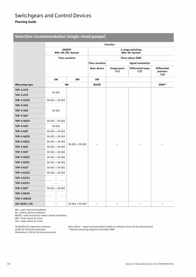
356 Subject to change without prior notice 09/2006 WILO AG
Switchgears and Control DevicesPlanning Guide
Selection recommendation (single-head pumps)
Wilo pump type
Function
ON/OFFWilo-SR-/SK-System
2-stage switchingWilo-SR-System
Time-sensitive Three-phase (DM)
Time-sensitive Signal transmitter
Basic device Temperature(+T)
Differential temp.( T)
Differential pressure
( p)
EM DM DM
WA WA/SE DDM1)
TOP-S 25/5SK 601
SK 601 + SK 602 – – – –
TOP-S 25/7
TOP-S 25/10 SK 601 + SK 602
TOP-S 30/4
SK 601TOP-S 30/5
TOP-S 30/7
TOP-S 30/10 SK 601 + SK 602
TOP-S 40/4 SK 601
TOP-S 40/7 SK 601 + SK 602
TOP-S 40/10 SK 601 + SK 602
TOP-S 40/15 SK 601 + SK 602
TOP-S 50/4 SK 601 + SK 602
TOP-S 50/7 SK 601 + SK 602
TOP-S 50/10 SK 601 + SK 602
TOP-S 50/15 SK 601 + SK 602
TOP-S 65/7 SK 601 + SK 602
TOP-S 65/10 SK 601 + SK 602
TOP-S 65/13 –
TOP-S 65/15 –
TOP-S 80/7 SK 601 + SK 602
TOP-S 80/10 –
TOP-S 100/10 –
AXL 80/25-130 – SK 601 + SK 602 – – – –
WA = wall-mounted installationSE = switch cabinet installationWA/SE = wall-mounted or switch cabinet installationDM = three-phase AC motorEM = single-phase AC motor
SK 602/SK 622 required as contactorand/or for full motor protectionAlternative: C-SK for full motor protection
Basic device + signal transmitter/load module according to choice (to be ordered extra)1) Specify measuring range for transmitter DDM
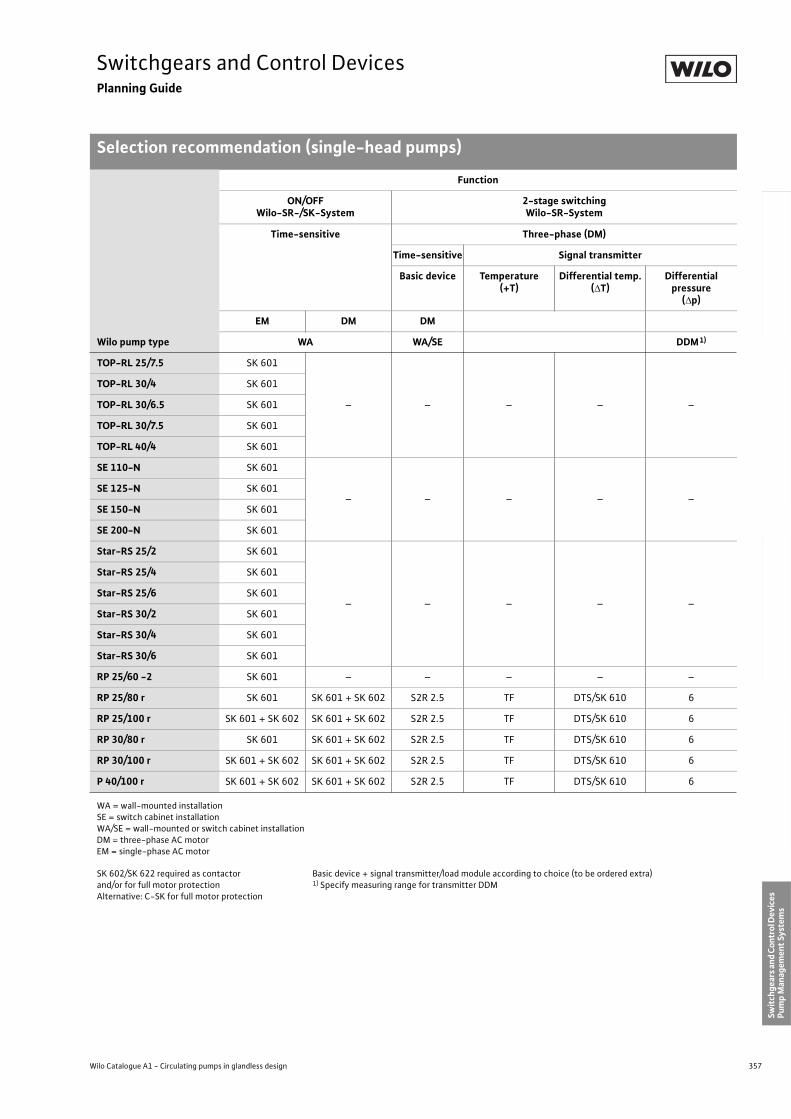
357
Switchgears and Control DevicesPlanning Guide
Selection recommendation (single-head pumps)
Wilo Catalogue A1 - Circulating pumps in glandless design
Hea
tin
g, A
ir-c
on
dit
ion
ing
, C
oo
ling
Po
tab
le w
ater
cir
cula
tio
nSo
lar
ther
mal
Serv
ice/
Acc
esso
ries
, Sys
tem
sSw
itch
gear
s an
d C
ontr
ol D
evic
es
Pum
p M
anag
emen
t Sy
stem
s
TOP-RL 25/7.5 SK 601
– – – – –
TOP-RL 30/4 SK 601
TOP-RL 30/6.5 SK 601
TOP-RL 30/7.5 SK 601
TOP-RL 40/4 SK 601
SE 110-N SK 601
– – – – –SE 125-N SK 601
SE 150-N SK 601
SE 200-N SK 601
Star-RS 25/2 SK 601
– – – – –
Star-RS 25/4 SK 601
Star-RS 25/6 SK 601
Star-RS 30/2 SK 601
Star-RS 30/4 SK 601
Star-RS 30/6 SK 601
RP 25/60 -2 SK 601 – – – – –
RP 25/80 r SK 601 SK 601 + SK 602 S2R 2.5 TF DTS/SK 610 6
RP 25/100 r SK 601 + SK 602 SK 601 + SK 602 S2R 2.5 TF DTS/SK 610 6
RP 30/80 r SK 601 SK 601 + SK 602 S2R 2.5 TF DTS/SK 610 6
RP 30/100 r SK 601 + SK 602 SK 601 + SK 602 S2R 2.5 TF DTS/SK 610 6
P 40/100 r SK 601 + SK 602 SK 601 + SK 602 S2R 2.5 TF DTS/SK 610 6
Wilo pump type
Function
ON/OFFWilo-SR-/SK-System
2-stage switchingWilo-SR-System
Time-sensitive Three-phase (DM)
Time-sensitive Signal transmitter
Basic device Temperature(+T)
Differential temp.( T)
Differential pressure
( p)
EM DM DM
WA WA/SE DDM1)
WA = wall-mounted installationSE = switch cabinet installationWA/SE = wall-mounted or switch cabinet installationDM = three-phase AC motorEM = single-phase AC motor
SK 602/SK 622 required as contactorand/or for full motor protectionAlternative: C-SK for full motor protection
Basic device + signal transmitter/load module according to choice (to be ordered extra)1) Specify measuring range for transmitter DDM
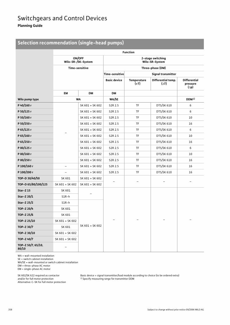
358 Subject to change without prior notice 09/2006 WILO AG
Switchgears and Control DevicesPlanning Guide
Selection recommendation (single-head pumps)
P 40/160 r
–
SK 601 + SK 602 S2R 2.5 TF DTS/SK 610 6
P 50/125 r SK 601 + SK 602 S2R 2.5 TF DTS/SK 610 6
P 50/160 r SK 601 + SK 602 S2R 2.5 TF DTS/SK 610 10
P 50/250 r SK 601 + SK 602 S2R 2.5 TF DTS/SK 610 16
P 65/125 r SK 601 + SK 602 S2R 2.5 TF DTS/SK 610 6
P 65/160 r SK 601 + SK 602 S2R 2.5 TF DTS/SK 610 10
P 65/250 r SK 601 + SK 602 S2R 2.5 TF DTS/SK 610 16
P 80/125 r SK 601 + SK 602 S2R 2.5 TF DTS/SK 610 6
P 80/160 r SK 601 + SK 602 S2R 2.5 TF DTS/SK 610 10
P 80/250 r SK 601 + SK 602 S2R 2.5 TF DTS/SK 610 16
P 100/160 r – SK 601 + SK 602 S2R 2.5 TF DTS/SK 610 16
P 100/200 r – SK 601 + SK 602 S2R 2.5 TF DTS/SK 610 16
TOP-D 30/40/50 SK 601 SK 601 + SK 602– – – –
TOP-D 65/80/100/125 SK 601 + SK 602 SK 601 + SK 602
Star-Z 15 SK 601–
– – – –
Star-Z 20/1 S1R-h
Star-Z 25/2 S1R-h
SK 601 + SK 602
TOP-Z 20/4 SK 601
TOP-Z 25/6 SK 601
TOP-Z 25/10 SK 601 + SK 602
TOP-Z 30/7 SK 601
TOP-Z 30/10 SK 601 + SK 602
TOP-Z 40/7 SK 601 + SK 602
TOP-Z 50/7, 65/10,80/10
–
Wilo pump type
Function
ON/OFFWilo-SR-/SK-System
2-stage switchingWilo-SR-System
Time-sensitive Three-phase (DM)
Time-sensitive Signal transmitter
Basic device Temperature(+T)
Differential temp.( T)
Differential pressure
( p)
EM DM DM
WA WA/SE DDM1)
WA = wall-mounted installationSE = switch cabinet installationWA/SE = wall-mounted or switch cabinet installationDM = three-phase AC motorEM = single-phase AC motor
SK 602/SK 622 required as contactorand/or for full motor protectionAlternative: C-SK for full motor protection
Basic device + signal transmitter/load module according to choice (to be ordered extra)1) Specify measuring range for transmitter DDM
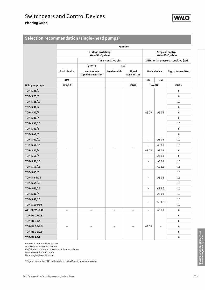
359
Switchgears and Control DevicesPlanning Guide
Selection recommendation (single-head pumps)
Wilo Catalogue A1 - Circulating pumps in glandless design
Hea
tin
g, A
ir-c
on
dit
ion
ing
, C
oo
ling
Po
tab
le w
ater
cir
cula
tio
nSo
lar
ther
mal
Serv
ice/
Acc
esso
ries
, Sys
tem
sSw
itch
gear
s an
d C
ontr
ol D
evic
es
Pum
p M
anag
emen
t Sy
stem
s
Wilo pump type
Function
4-stage switchingWilo-SR-System
Stepless controlWilo-AS-System
Time-sensitive plus Differential pressure-sensitive ( p)
(+T/ T) ( p)
Basic device Load modulesignal transmitter
Load module Signal transmitter
Basic device Signal transmitter
DM EM DM
WA/SE DDM WA/SE DDS1)
TOP-S 25/5
– – – –
AS 08 AS 08
6
TOP-S 25/7 6
TOP-S 25/10 10
TOP-S 30/4 6
TOP-S 30/5 6
TOP-S 30/7 6
TOP-S 30/10 10
TOP-S 40/4 6
TOP-S 40/7 6
TOP-S 40/10 – AS 08 10
TOP-S 40/15 – AS 08 16
TOP-S 50/4 AS 08 AS 08 6
TOP-S 50/7 – AS 08 6
TOP-S 50/10 – AS 08 10
TOP-S 50/15 – AS 1.5 16
TOP-S 65/7
– AS 08
10
TOP-S 65/10 16
TOP-S 65/13 16
TOP-S 65/15 – AS 1.5 16
TOP-S 80/7 – AS 08 10
TOP-S 80/10– AS 1.5
10
TOP-S 100/10 10
AXL 80/25-130 – – – – – AS 08 6
TOP-RL 25/7.5
– – – – AS 08 –
6
TOP-RL 30/4 6
TOP-RL 30/6.5 6
TOP-RL 30/7.5 6
TOP-RL 40/4 6
WA = wall-mounted installationSE = switch cabinet installationWA/SE = wall-mounted or switch cabinet installationDM = three-phase AC motorEM = single-phase AC motor
1) Signal transmitter DDS (to be ordered extra) Specify measuring range
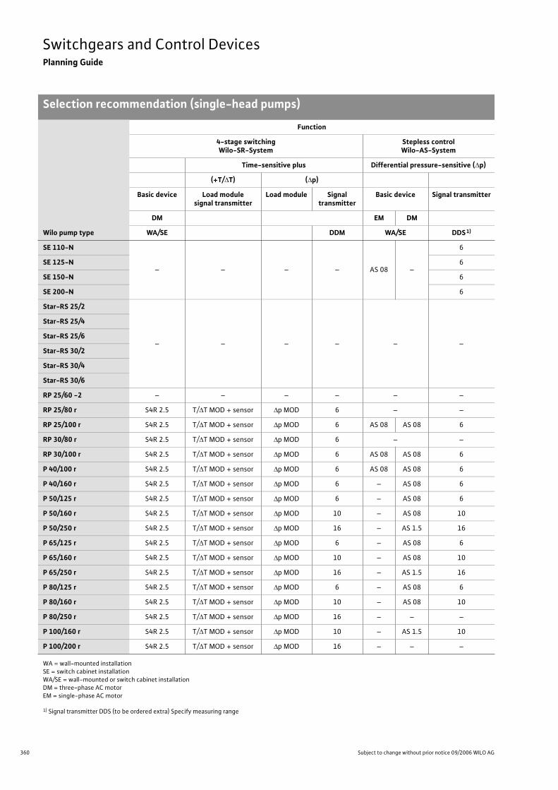
360 Subject to change without prior notice 09/2006 WILO AG
Switchgears and Control DevicesPlanning Guide
Selection recommendation (single-head pumps)
SE 110-N
– – – – AS 08 –
6
SE 125-N 6
SE 150-N 6
SE 200-N 6
Star-RS 25/2
– – – – – –
Star-RS 25/4
Star-RS 25/6
Star-RS 30/2
Star-RS 30/4
Star-RS 30/6
RP 25/60 -2 – – – – – –
RP 25/80 r S4R 2.5 T/ T MOD + sensor p MOD 6 – –
RP 25/100 r S4R 2.5 T/ T MOD + sensor p MOD 6 AS 08 AS 08 6
RP 30/80 r S4R 2.5 T/ T MOD + sensor p MOD 6 – –
RP 30/100 r S4R 2.5 T/ T MOD + sensor p MOD 6 AS 08 AS 08 6
P 40/100 r S4R 2.5 T/ T MOD + sensor p MOD 6 AS 08 AS 08 6
P 40/160 r S4R 2.5 T/ T MOD + sensor p MOD 6 – AS 08 6
P 50/125 r S4R 2.5 T/ T MOD + sensor p MOD 6 – AS 08 6
P 50/160 r S4R 2.5 T/ T MOD + sensor p MOD 10 – AS 08 10
P 50/250 r S4R 2.5 T/ T MOD + sensor p MOD 16 – AS 1.5 16
P 65/125 r S4R 2.5 T/ T MOD + sensor p MOD 6 – AS 08 6
P 65/160 r S4R 2.5 T/ T MOD + sensor p MOD 10 – AS 08 10
P 65/250 r S4R 2.5 T/ T MOD + sensor p MOD 16 – AS 1.5 16
P 80/125 r S4R 2.5 T/ T MOD + sensor p MOD 6 – AS 08 6
P 80/160 r S4R 2.5 T/ T MOD + sensor p MOD 10 – AS 08 10
P 80/250 r S4R 2.5 T/ T MOD + sensor p MOD 16 – – –
P 100/160 r S4R 2.5 T/ T MOD + sensor p MOD 10 – AS 1.5 10
P 100/200 r S4R 2.5 T/ T MOD + sensor p MOD 16 – – –
Wilo pump type
Function
4-stage switchingWilo-SR-System
Stepless controlWilo-AS-System
Time-sensitive plus Differential pressure-sensitive ( p)
(+T/ T) ( p)
Basic device Load modulesignal transmitter
Load module Signal transmitter
Basic device Signal transmitter
DM EM DM
WA/SE DDM WA/SE DDS1)
WA = wall-mounted installationSE = switch cabinet installationWA/SE = wall-mounted or switch cabinet installationDM = three-phase AC motorEM = single-phase AC motor
1) Signal transmitter DDS (to be ordered extra) Specify measuring range
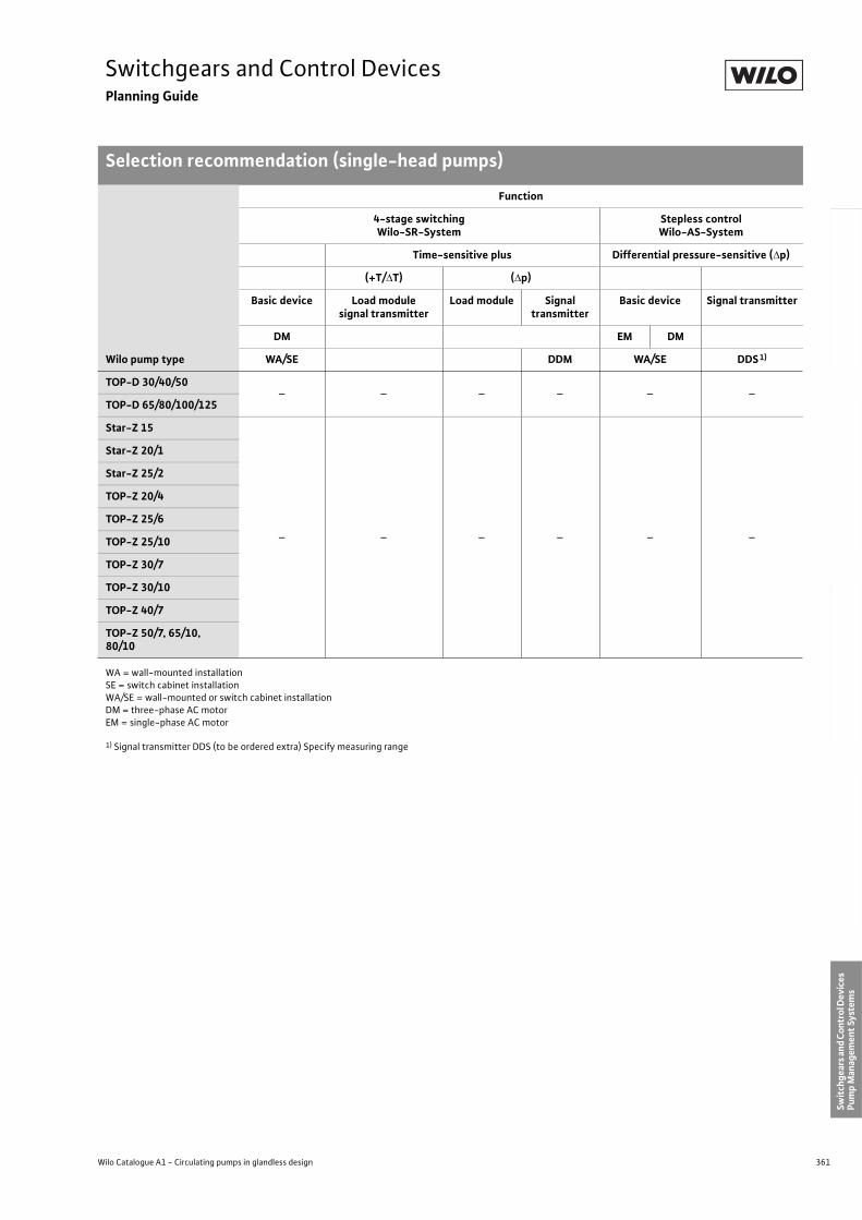
361
Switchgears and Control DevicesPlanning Guide
Selection recommendation (single-head pumps)
Wilo Catalogue A1 - Circulating pumps in glandless design
Hea
tin
g, A
ir-c
on
dit
ion
ing
, C
oo
ling
Po
tab
le w
ater
cir
cula
tio
nSo
lar
ther
mal
Serv
ice/
Acc
esso
ries
, Sys
tem
sSw
itch
gear
s an
d C
ontr
ol D
evic
es
Pum
p M
anag
emen
t Sy
stem
s
TOP-D 30/40/50– – – – – –
TOP-D 65/80/100/125
Star-Z 15
– – – – – –
Star-Z 20/1
Star-Z 25/2
TOP-Z 20/4
TOP-Z 25/6
TOP-Z 25/10
TOP-Z 30/7
TOP-Z 30/10
TOP-Z 40/7
TOP-Z 50/7, 65/10,80/10
Wilo pump type
Function
4-stage switchingWilo-SR-System
Stepless controlWilo-AS-System
Time-sensitive plus Differential pressure-sensitive ( p)
(+T/ T) ( p)
Basic device Load modulesignal transmitter
Load module Signal transmitter
Basic device Signal transmitter
DM EM DM
WA/SE DDM WA/SE DDS1)
WA = wall-mounted installationSE = switch cabinet installationWA/SE = wall-mounted or switch cabinet installationDM = three-phase AC motorEM = single-phase AC motor
1) Signal transmitter DDS (to be ordered extra) Specify measuring range
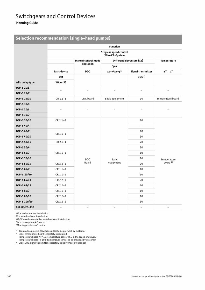
362 Subject to change without prior notice 09/2006 WILO AG
Switchgears and Control DevicesPlanning Guide
Selection recommendation (single-head pumps)
Wilo pump type
Function
Stepless speed controlWilo-CR-System
Manual control modeoperation
Differential pressure ( p) Temperature
p-c
Basic device DDC p-v/ p-q 1) Signal transmitter ±T T
DM DDG3)
WA or SE
TOP-S 25/5– – – – –
TOP-S 25/7
TOP-S 25/10 CR 1.1-1 DDC board Basic equipment 10 Temperature board
TOP-S 30/4
– – – – –TOP-S 30/5
TOP-S 30/7
TOP-S 30/10 CR 1.1–1
DDCBoard
Basicequipment
10
Temperatureboard 2)
TOP-S 40/4 – –
TOP-S 40/7CR 1.1–1
10
TOP-S 40/10 10
TOP-S 40/15 CR 2.2-1 20
TOP-S 50/4
CR 1.1–1
10
TOP-S 50/7 10
TOP-S 50/10 10
TOP-S 50/15 CR 2.2–1 20
TOP-S 65/7 CR 1.1–1 10
TOP-S 65/10 CR 1.1–1 10
TOP-S 65/13 CR 2.2–1 20
TOP-S 65/15 CR 2.2–1 20
TOP-S 80/7 CR 1.1–1 10
TOP-S 80/10 CR 2.2–1 10
TOP-S 100/10 CR 2.2–1 10
AXL 80/25-130 – – – – –
WA = wall-mounted installationSE = switch cabinet installationWA/SE = wall-mounted or switch cabinet installationDM = three-phase AC motorEM = single-phase AC motor
1) Required volumetric-flow transmitter to be provided by customer2) Order temperature board separately as required:
Temperature board KTY 10: Temperature sensor TSG in the scope of delivery Temperature board PT 100: Temperature sensor to be provided by customer
3) Order DDG signal transmitter separately (specify measuring range)
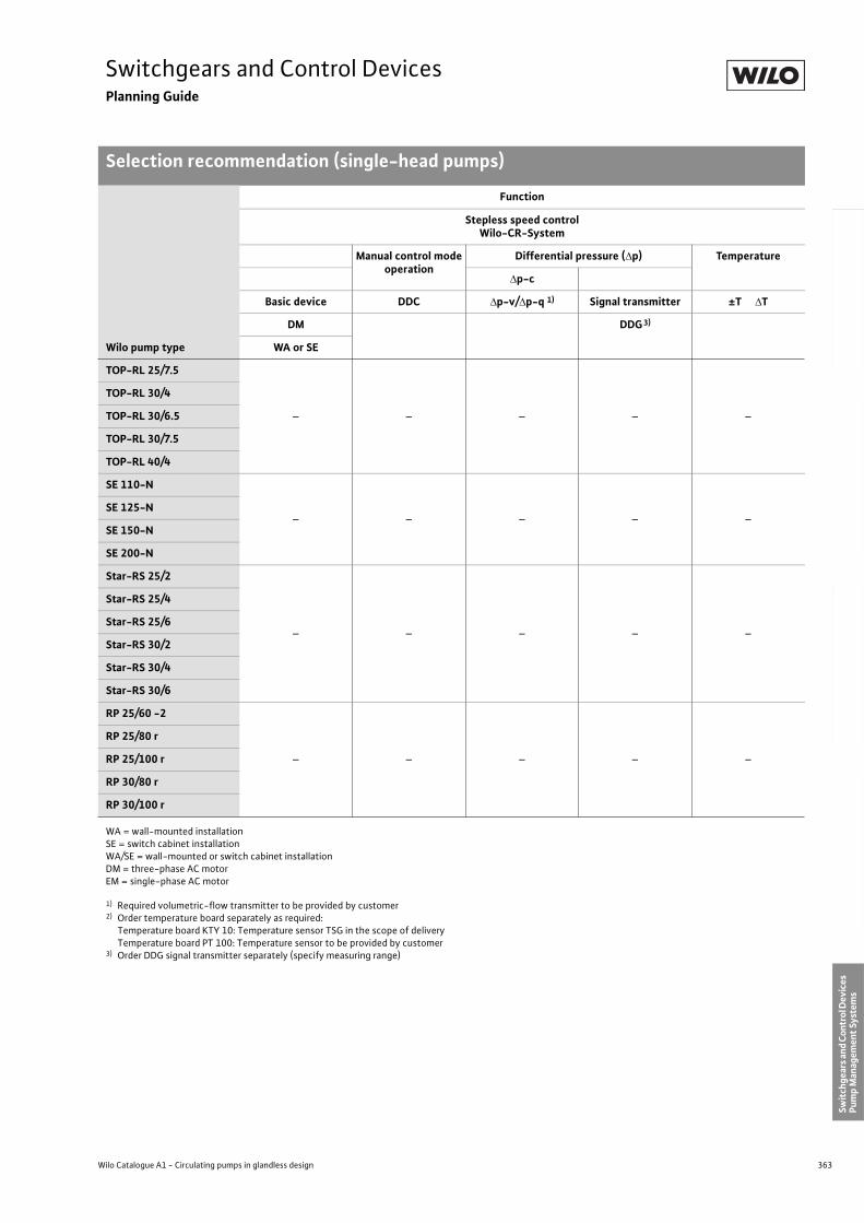
363
Switchgears and Control DevicesPlanning Guide
Selection recommendation (single-head pumps)
Wilo Catalogue A1 - Circulating pumps in glandless design
Hea
tin
g, A
ir-c
on
dit
ion
ing
, C
oo
ling
Po
tab
le w
ater
cir
cula
tio
nSo
lar
ther
mal
Serv
ice/
Acc
esso
ries
, Sys
tem
sSw
itch
gear
s an
d C
ontr
ol D
evic
es
Pum
p M
anag
emen
t Sy
stem
s
TOP-RL 25/7.5
– – – – –
TOP-RL 30/4
TOP-RL 30/6.5
TOP-RL 30/7.5
TOP-RL 40/4
SE 110-N
– – – – –SE 125-N
SE 150-N
SE 200-N
Star-RS 25/2
– – – – –
Star-RS 25/4
Star-RS 25/6
Star-RS 30/2
Star-RS 30/4
Star-RS 30/6
RP 25/60 -2
– – – – –
RP 25/80 r
RP 25/100 r
RP 30/80 r
RP 30/100 r
Wilo pump type
Function
Stepless speed controlWilo-CR-System
Manual control modeoperation
Differential pressure ( p) Temperature
p-c
Basic device DDC p-v/ p-q 1) Signal transmitter ±T T
DM DDG3)
WA or SE
WA = wall-mounted installationSE = switch cabinet installationWA/SE = wall-mounted or switch cabinet installationDM = three-phase AC motorEM = single-phase AC motor
1) Required volumetric-flow transmitter to be provided by customer2) Order temperature board separately as required:
Temperature board KTY 10: Temperature sensor TSG in the scope of delivery Temperature board PT 100: Temperature sensor to be provided by customer
3) Order DDG signal transmitter separately (specify measuring range)
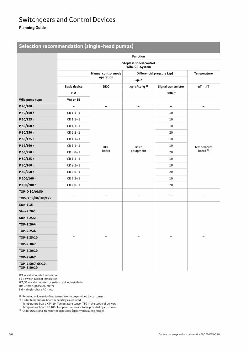
364 Subject to change without prior notice 09/2006 WILO AG
Switchgears and Control DevicesPlanning Guide
Selection recommendation (single-head pumps)
P 40/100 r – – – – –
P 40/160 r CR 1.1–1
DDCboard
Basicequipment
10
Temperatureboard 2)
P 50/125 r CR 1.1–1 10
P 50/160 r CR 1.1–1 10
P 50/250 r CR 2.2–1 20
P 65/125 r CR 1.1–1 10
P 65/160 r CR 1.1–1 10
P 65/250 r CR 3.0–1 20
P 80/125 r CR 1.1–1 10
P 80/160 r CR 2.2–1 10
P 80/250 r CR 4.0–1 20
P 100/160 r CR 2.2–1 10
P 100/200 r CR 4.0–1 20
TOP-D 30/40/50– – – – –
TOP-D 65/80/100/125
Star-Z 15
– – – – –
Star-Z 20/1
Star-Z 25/2
TOP-Z 20/4
TOP-Z 25/6
TOP-Z 25/10
TOP-Z 30/7
TOP-Z 30/10
TOP-Z 40/7
TOP-Z 50/7, 65/10,TOP-Z 80/10
Wilo pump type
Function
Stepless speed controlWilo-CR-System
Manual control modeoperation
Differential pressure ( p) Temperature
p-c
Basic device DDC p-v/ p-q 1) Signal transmitter ±T T
DM DDG3)
WA or SE
WA = wall-mounted installationSE = switch cabinet installationWA/SE = wall-mounted or switch cabinet installationDM = three-phase AC motorEM = single-phase AC motor
1) Required volumetric-flow transmitter to be provided by customer2) Order temperature board separately as required:
Temperature board KTY 10: Temperature sensor TSG in the scope of delivery Temperature board PT 100: Temperature sensor to be provided by customer
3) Order DDG signal transmitter separately (specify measuring range)
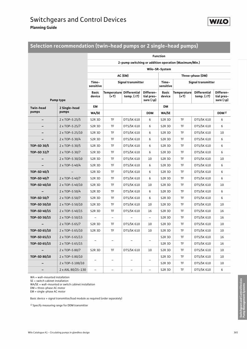
365
Switchgears and Control DevicesPlanning Guide
Selection recommendation (twin-head pumps or 2 single-head pumps)
Wilo Catalogue A1 - Circulating pumps in glandless design
Hea
tin
g, A
ir-c
on
dit
ion
ing
, C
oo
ling
Po
tab
le w
ater
cir
cula
tio
nSo
lar
ther
mal
Serv
ice/
Acc
esso
ries
, Sys
tem
sSw
itch
gear
s an
d C
ontr
ol D
evic
es
Pum
p M
anag
emen
t Sy
stem
s
Pump type
Function
2-pump switching or addition operation (Maximum/Min.)
Wilo-SR-System
AC (EM) Three-phase (DM)
Time-sensitive
Signal transmitter Time-sensitive
Signal transmitter
Basic device
Temperature(+T)
Differential temp. ( T)
Differen-tial pres-sure ( p)
Basic device
Temperature(+T)
Differential temp. ( T)
Differen-tial pres-sure ( p)
Twin-head pumps
2 Single-head pumps
EM DM
WA/SE DDM WA/SE DDM1)
– 2 x TOP-S 25/5 S2R 3D TF DTS/SK 610 6 S2R 3D TF DTS/SK 610 6
– 2 x TOP-S 25/7 S2R 3D TF DTS/SK 610 6 S2R 3D TF DTS/SK 610 6
– 2 x TOP-S 25/10 S2R 3D TF DTS/SK 610 6 S2R 3D TF DTS/SK 610 10
– 2 x TOP-S 30/4 S2R 3D TF DTS/SK 610 6 S2R 3D TF DTS/SK 610 6
TOP-SD 30/5 2 x TOP-S 30/5 S2R 3D TF DTS/SK 610 6 S2R 3D TF DTS/SK 610 6
TOP-SD 32/7 2 x TOP-S 30/7 S2R 3D TF DTS/SK 610 6 S2R 3D TF DTS/SK 610 6
– 2 x TOP-S 30/10 S2R 3D TF DTS/SK 610 10 S2R 3D TF DTS/SK 610 10
– 2 x TOP-S 40/4 S2R 3D TF DTS/SK 610 6 S2R 3D TF DTS/SK 610 6
TOP-SD 40/3 – S2R 3D TF DTS/SK 610 6 S2R 3D TF DTS/SK 610 6
TOP-SD 40/7 2 x TOP-S 40/7 S2R 3D TF DTS/SK 610 6 S2R 3D TF DTS/SK 610 6
TOP-SD 40/10 2 x TOP-S 40/10 S2R 3D TF DTS/SK 610 10 S2R 3D TF DTS/SK 610 10
– 2 x TOP-S 50/4 S2R 3D TF DTS/SK 610 6 S2R 3D TF DTS/SK 610 6
TOP-SD 50/7 2 x TOP-S 50/7 S2R 3D TF DTS/SK 610 6 S2R 3D TF DTS/SK 610 6
TOP-SD 50/10 2 x TOP-S 50/10 S2R 3D TF DTS/SK 610 10 S2R 3D TF DTS/SK 610 10
TOP-SD 40/15 2 x TOP-S 40/15 S2R 3D TF DTS/SK 610 16 S2R 3D TF DTS/SK 610 16
TOP-SD 50/15 2 x TOP-S 50/15 – – – – S2R 3D TF DTS/SK 610 16
– 2 x TOP-S 65/7 S2R 3D TF DTS/SK 610 10 S2R 3D TF DTS/SK 610 10
TOP-SD 65/10 2 x TOP-S 65/10 S2R 3D TF DTS/SK 610 10 S2R 3D TF DTS/SK 610 10
TOP-SD 65/13 2 x TOP-S 65/13– – – –
S2R 3D TF DTS/SK 610 16
TOP-SD 65/15 2 x TOP-S 65/15 S2R 3D TF DTS/SK 610 16
– 2 x TOP-S 80/7 S2R 3D TF DTS/SK 610 10 S2R 3D TF DTS/SK 610 10
TOP-SD 80/10 2 x TOP-S 80/10– – – –
S2R 3D TF DTS/SK 610 10
– 2 x TOP-S 100/10 S2R 3D TF DTS/SK 610 10
– 2 x AXL 80/25-130 – – – – S2R 3D TF DTS/SK 610 6
WA = wall-mounted installationSE = switch cabinet installationWA/SE = wall-mounted or switch cabinet installationDM = three-phase AC motorEM = single-phase AC motor
Basic device + signal transmitter/load module as required (order separately)
1) Specify measuring range for DDM transmitter
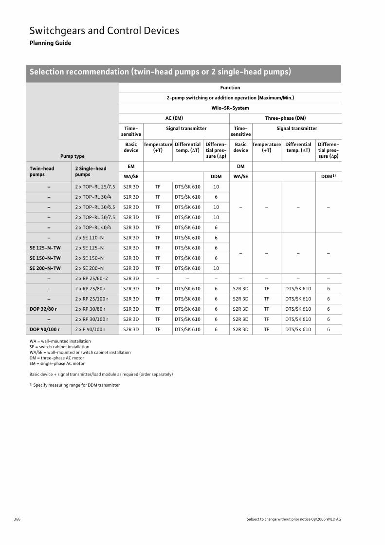
366 Subject to change without prior notice 09/2006 WILO AG
Switchgears and Control DevicesPlanning Guide
Selection recommendation (twin-head pumps or 2 single-head pumps)
– 2 x TOP-RL 25/7.5 S2R 3D TF DTS/SK 610 10
– – – –
– 2 x TOP-RL 30/4 S2R 3D TF DTS/SK 610 6
– 2 x TOP-RL 30/6.5 S2R 3D TF DTS/SK 610 10
– 2 x TOP-RL 30/7.5 S2R 3D TF DTS/SK 610 10
– 2 x TOP-RL 40/4 S2R 3D TF DTS/SK 610 6
– 2 x SE 110-N S2R 3D TF DTS/SK 610 6
– – – –SE 125-N-TW 2 x SE 125-N S2R 3D TF DTS/SK 610 6
SE 150-N-TW 2 x SE 150-N S2R 3D TF DTS/SK 610 6
SE 200-N-TW 2 x SE 200-N S2R 3D TF DTS/SK 610 10
– 2 x RP 25/60-2 S2R 3D – – – – – – –
– 2 x RP 25/80 r S2R 3D TF DTS/SK 610 6 S2R 3D TF DTS/SK 610 6
– 2 x RP 25/100 r S2R 3D TF DTS/SK 610 6 S2R 3D TF DTS/SK 610 6
DOP 32/80 r 2 x RP 30/80 r S2R 3D TF DTS/SK 610 6 S2R 3D TF DTS/SK 610 6
– 2 x RP 30/100 r S2R 3D TF DTS/SK 610 6 S2R 3D TF DTS/SK 610 6
DOP 40/100 r 2 x P 40/100 r S2R 3D TF DTS/SK 610 6 S2R 3D TF DTS/SK 610 6
Pump type
Function
2-pump switching or addition operation (Maximum/Min.)
Wilo-SR-System
AC (EM) Three-phase (DM)
Time-sensitive
Signal transmitter Time-sensitive
Signal transmitter
Basic device
Temperature(+T)
Differential temp. ( T)
Differen-tial pres-sure ( p)
Basic device
Temperature(+T)
Differential temp. ( T)
Differen-tial pres-sure ( p)
Twin-head pumps
2 Single-head pumps
EM DM
WA/SE DDM WA/SE DDM1)
WA = wall-mounted installationSE = switch cabinet installationWA/SE = wall-mounted or switch cabinet installationDM = three-phase AC motorEM = single-phase AC motor
Basic device + signal transmitter/load module as required (order separately)
1) Specify measuring range for DDM transmitter
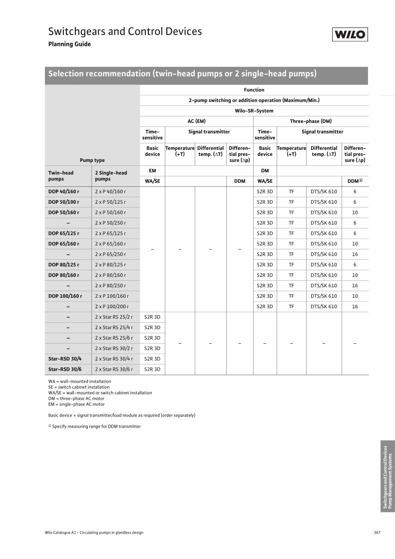
367
Switchgears and Control DevicesPlanning Guide
Selection recommendation (twin-head pumps or 2 single-head pumps)
Wilo Catalogue A1 - Circulating pumps in glandless design
Hea
tin
g, A
ir-c
on
dit
ion
ing
, C
oo
ling
Po
tab
le w
ater
cir
cula
tio
nSo
lar
ther
mal
Serv
ice/
Acc
esso
ries
, Sys
tem
sSw
itch
gear
s an
d C
ontr
ol D
evic
es
Pum
p M
anag
emen
t Sy
stem
s
DOP 40/160 r 2 x P 40/160 r
– – – –
S2R 3D TF DTS/SK 610 6
DOP 50/100 r 2 x P 50/125 r S2R 3D TF DTS/SK 610 6
DOP 50/160 r 2 x P 50/160 r S2R 3D TF DTS/SK 610 10
– 2 x P 50/250 r S2R 3D TF DTS/SK 610 6
DOP 65/125 r 2 x P 65/125 r S2R 3D TF DTS/SK 610 6
DOP 65/160 r 2 x P 65/160 r S2R 3D TF DTS/SK 610 10
– 2 x P 65/250 r S2R 3D TF DTS/SK 610 16
DOP 80/125 r 2 x P 80/125 r S2R 3D TF DTS/SK 610 6
DOP 80/160 r 2 x P 80/160 r S2R 3D TF DTS/SK 610 10
– 2 x P 80/250 r S2R 3D TF DTS/SK 610 16
DOP 100/160 r 2 x P 100/160 r S2R 3D TF DTS/SK 610 10
– 2 x P 100/200 r S2R 3D TF DTS/SK 610 16
– 2 x Star RS 25/2 r S2R 3D
– – – – – – –
– 2 x Star RS 25/4 r S2R 3D
– 2 x Star RS 25/6 r S2R 3D
– 2 x Star RS 30/2 r S2R 3D
Star-RSD 30/4 2 x Star RS 30/4 r S2R 3D
Star-RSD 30/6 2 x Star RS 30/6 r S2R 3D
Pump type
Function
2-pump switching or addition operation (Maximum/Min.)
Wilo-SR-System
AC (EM) Three-phase (DM)
Time-sensitive
Signal transmitter Time-sensitive
Signal transmitter
Basic device
Temperature(+T)
Differential temp. ( T)
Differen-tial pres-sure ( p)
Basic device
Temperature(+T)
Differential temp. ( T)
Differen-tial pres-sure ( p)
Twin-head pumps
2 Single-head pumps
EM DM
WA/SE DDM WA/SE DDM1)
WA = wall-mounted installationSE = switch cabinet installationWA/SE = wall-mounted or switch cabinet installationDM = three-phase AC motorEM = single-phase AC motor
Basic device + signal transmitter/load module as required (order separately)
1) Specify measuring range for DDM transmitter
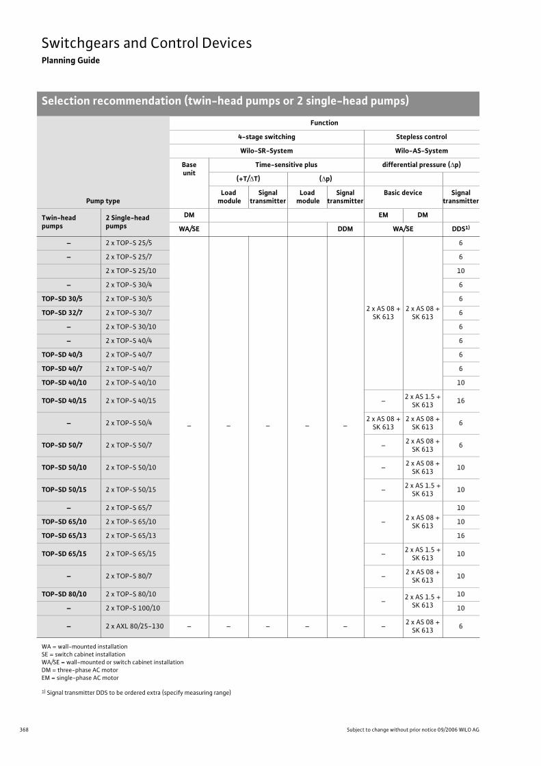
368 Subject to change without prior notice 09/2006 WILO AG
Switchgears and Control DevicesPlanning Guide
Selection recommendation (twin-head pumps or 2 single-head pumps)
Pump type
Function
4-stage switching Stepless control
Wilo-SR-System Wilo-AS-System
Baseunit
Time-sensitive plus differential pressure ( p)
(+T/ T) ( p)
Load module
Signal transmitter
Load module
Signaltransmitter
Basic device Signal transmitter
Twin-head pumps
2 Single-head pumps
DM EM DM
WA/SE DDM WA/SE DDS1)
– 2 x TOP-S 25/5
– – – – –
2 x AS 08 + SK 613
2 x AS 08 + SK 613
6
– 2 x TOP-S 25/7 6
2 x TOP-S 25/10 10
– 2 x TOP-S 30/4 6
TOP-SD 30/5 2 x TOP-S 30/5 6
TOP-SD 32/7 2 x TOP-S 30/7 6
– 2 x TOP-S 30/10 6
– 2 x TOP-S 40/4 6
TOP-SD 40/3 2 x TOP-S 40/7 6
TOP-SD 40/7 2 x TOP-S 40/7 6
TOP-SD 40/10 2 x TOP-S 40/10 10
TOP-SD 40/15 2 x TOP-S 40/15 –2 x AS 1.5 +
SK 61316
– 2 x TOP-S 50/42 x AS 08 +
SK 6132 x AS 08 +
SK 6136
TOP-SD 50/7 2 x TOP-S 50/7 –2 x AS 08 +
SK 6136
TOP-SD 50/10 2 x TOP-S 50/10 –2 x AS 08 +
SK 61310
TOP-SD 50/15 2 x TOP-S 50/15 –2 x AS 1.5 +
SK 61310
– 2 x TOP-S 65/7
–2 x AS 08 +
SK 613
10
TOP-SD 65/10 2 x TOP-S 65/10 10
TOP-SD 65/13 2 x TOP-S 65/13 16
TOP-SD 65/15 2 x TOP-S 65/15 –2 x AS 1.5 +
SK 61310
– 2 x TOP-S 80/7 –2 x AS 08 +
SK 61310
TOP-SD 80/10 2 x TOP-S 80/10–
2 x AS 1.5 + SK 613
10
– 2 x TOP-S 100/10 10
– 2 x AXL 80/25-130 – – – – – –2 x AS 08 +
SK 6136
WA = wall-mounted installationSE = switch cabinet installationWA/SE = wall-mounted or switch cabinet installationDM = three-phase AC motorEM = single-phase AC motor
1) Signal transmitter DDS to be ordered extra (specify measuring range)
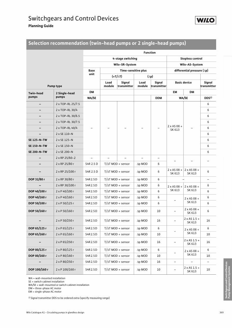
369
Switchgears and Control DevicesPlanning Guide
Selection recommendation (twin-head pumps or 2 single-head pumps)
Wilo Catalogue A1 - Circulating pumps in glandless design
Hea
tin
g, A
ir-c
on
dit
ion
ing
, C
oo
ling
Po
tab
le w
ater
cir
cula
tio
nSo
lar
ther
mal
Serv
ice/
Acc
esso
ries
, Sys
tem
sSw
itch
gear
s an
d C
ontr
ol D
evic
es
Pum
p M
anag
emen
t Sy
stem
s
– 2 x TOP-RL 25/7.5
– – – – –2 x AS 08 +
SK 613–
6
– 2 x TOP-RL 30/4 6
– 2 x TOP-RL 30/6.5 6
– 2 x TOP-RL 30/7.5 6
– 2 x TOP-RL 40/4 6
– 2 x SE 110-N 6
SE 125-N-TW 2 x SE 125-N 6
SE 150-N-TW 2 x SE 150-N 6
SE 200-N-TW 2 x SE 200-N 6
– 2 x RP 25/60-2 – – – – –– – –
– 2 x RP 25/80 r S4R 2.5 D T/ T MOD + sensor p MOD 6
– 2 x RP 25/100 r S4R 2.5 D T/ T MOD + sensor p MOD 62 x AS 08 +
SK 6132 x AS 08 +
SK 6136
DOP 32/80 r 2 x RP 30/80 r S4R 2.5 D T/ T MOD + sensor p MOD 6 – –
– 2 x RP 30/100 r S4R 2.5 D T/ T MOD + sensor p MOD 6 2 x AS 08 + SK 613
2 x AS 08 + SK 613
6
DOP 40/100 r 2 x P 40/100 r S4R 2.5 D T/ T MOD + sensor p MOD 6 6
DOP 40/160 r 2 x P 40/160 r S4R 2.5 D T/ T MOD + sensor p MOD 6–
2 x AS 08 + SK 613
6
DOP 50/100 r 2 x P 50/125 r S4R 2.5 D T/ T MOD + sensor p MOD 6 6
DOP 50/160 r 2 x P 50/160 r S4R 2.5 D T/ T MOD + sensor p MOD 10 –2 x AS 08 +
SK 6136
– 2 x P 50/250 r S4R 2.5 D T/ T MOD + sensor p MOD 16 –2 x AS 1.5 +
SK 61316
DOP 65/125 r 2 x P 65/125 r S4R 2.5 D T/ T MOD + sensor p MOD 6–
2 x AS 08 + SK 613
6
DOP 65/160 r 2 x P 65/160 r S4R 2.5 D T/ T MOD + sensor p MOD 10 10
– 2 x P 65/250 r S4R 2.5 D T/ T MOD + sensor p MOD 16 –2 x AS 1.5 +
SK 61316
DOP 80/125 r 2 x P 80/125 r S4R 2.5 D T/ T MOD + sensor p MOD 6–
2 x AS 08 + SK 613
6
DOP 80/160 r 2 x P 80/160 r S4R 2.5 D T/ T MOD + sensor p MOD 10 10
– 2 x P 80/250 r S4R 2.5 D T/ T MOD + sensor p MOD 16 – – –
DOP 100/160 r 2 x P 100/160 r S4R 2.5 D T/ T MOD + sensor p MOD 10 –2 x AS 1.5 +
SK 61310
Pump type
Function
4-stage switching Stepless control
Wilo-SR-System Wilo-AS-System
Baseunit
Time-sensitive plus differential pressure ( p)
(+T/ T) ( p)
Load module
Signal transmitter
Load module
Signaltransmitter
Basic device Signal transmitter
Twin-head pumps
2 Single-head pumps
DM EM DM
WA/SE DDM WA/SE DDS1)
WA = wall-mounted installationSE = switch cabinet installationWA/SE = wall-mounted or switch cabinet installationDM = three-phase AC motorEM = single-phase AC motor
1) Signal transmitter DDS to be ordered extra (specify measuring range)
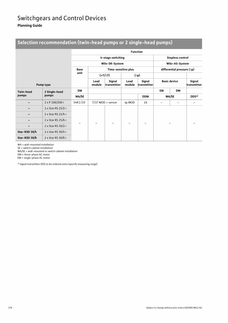
370 Subject to change without prior notice 09/2006 WILO AG
Switchgears and Control DevicesPlanning Guide
Selection recommendation (twin-head pumps or 2 single-head pumps)
– 2 x P 100/200 r S4R 2.5 D T/ T MOD + sensor p MOD 16 – – –
– 2 x Star RS 25/2 r
– – – – – – –
– 2 x Star RS 25/4 r
– 2 x Star RS 25/6 r
– 2 x Star RS 30/2 r
Star-RSD 30/4 2 x Star RS 30/4 r
Star-RSD 30/6 2 x Star RS 30/6 r
Pump type
Function
4-stage switching Stepless control
Wilo-SR-System Wilo-AS-System
Baseunit
Time-sensitive plus differential pressure ( p)
(+T/ T) ( p)
Load module
Signal transmitter
Load module
Signaltransmitter
Basic device Signal transmitter
Twin-head pumps
2 Single-head pumps
DM EM DM
WA/SE DDM WA/SE DDS1)
WA = wall-mounted installationSE = switch cabinet installationWA/SE = wall-mounted or switch cabinet installationDM = three-phase AC motorEM = single-phase AC motor
1) Signal transmitter DDS to be ordered extra (specify measuring range)
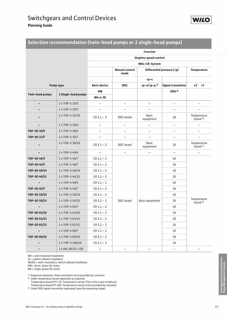
371
Switchgears and Control DevicesPlanning Guide
Selection recommendation (twin-head pumps or 2 single-head pumps)
Wilo Catalogue A1 - Circulating pumps in glandless design
Hea
tin
g, A
ir-c
on
dit
ion
ing
, C
oo
ling
Po
tab
le w
ater
cir
cula
tio
nSo
lar
ther
mal
Serv
ice/
Acc
esso
ries
, Sys
tem
sSw
itch
gear
s an
d C
ontr
ol D
evic
es
Pum
p M
anag
emen
t Sy
stem
s
Pump type
Function
Stepless speed control
Wilo-CR-System
Manual control mode
Differential pressure ( p) Temperature
p-c
Basic device DDC p-v/ p-q 1) Signal transmitter ±T T
Twin-head pumps 2 Single-head pumpsDM DDG3)
WA or SE
– 2 x TOP-S 25/5 – – – – –
– 2 x TOP-S 25/7 – – – – –
–2 x TOP-S 25/10
CR 1.1 – 2 DDC boardBasic
equipment10
Temperature board 2)
– 2 x TOP-S 30/4 – – – – –
TOP-SD 30/5 2 x TOP-S 30/5 – – – – –
TOP-SD 32/7 2 x TOP-S 30/7 – – – – –
–2 x TOP-S 30/10
CR 1.1 – 2 DDC boardBasic
equipment10
Temperature board 2)
– 2 x TOP-S 40/4 – – – – –
TOP-SD 40/3 2 x TOP-S 40/7 CR 1.1 – 2
DDC board Basic equipment
10
Temperature board 2)
TOP-SD 40/7 2 x TOP-S 40/7 CR 1.1 – 2 10
TOP-SD 40/10 2 x TOP-S 40/10 CR 1.1 – 2 10
TOP-SD 40/15 2 x TOP-S 40/15 CR 2.2 – 2 20
– 2 x TOP-S 50/4 CR 1.1 – 2 10
TOP-SD 50/7 2 x TOP-S 50/7 CR 1.1 – 2 10
TOP-SD 50/10 2 x TOP-S 50/10 CR 1.1 – 2 10
TOP-SD 50/15 2 x TOP-S 50/15 CR 2.2 – 2 20
– 2 x TOP-S 65/7 CR 1.1 – 2 10
TOP-SD 65/10 2 x TOP-S 65/10 CR 1.1 – 2 10
TOP-SD 65/13 2 x TOP-S 65/13 CR 2.2 – 2 20
TOP-SD 65/15 2 x TOP-S 65/15 CR 2.2 – 2 20
– 2 x TOP-S 80/7 CR 1.1 – 2 10
TOP-SD 80/10 2 x TOP-S 80/10 CR 2.2 – 2 10
– 2 x TOP-S 100/10 CR 2.2 – 2 10
– 2 x AXL 80/25-130 – – – – –
WA = wall-mounted installationSE = switch cabinet installationWA/SE = wall-mounted or switch cabinet installationDM = three-phase AC motorEM = single-phase AC motor
1) Required volumetric-flow transmitter to be provided by customer2) Order temperature board separately as required:
Temperature board KTY 10: Temperature sensor TSG in the scope of delivery Temperature board PT 100: Temperature sensor to be provided by customer
3) Order DDG signal transmitter separately (specify measuring range)
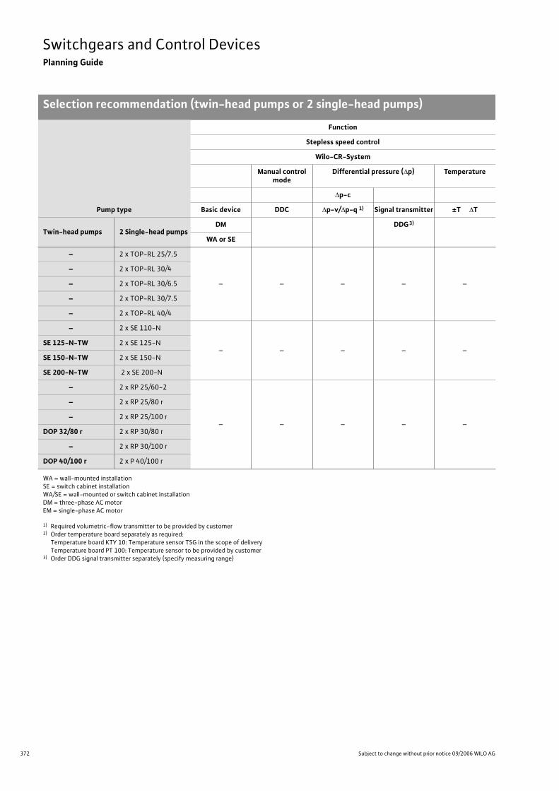
372 Subject to change without prior notice 09/2006 WILO AG
Switchgears and Control DevicesPlanning Guide
Selection recommendation (twin-head pumps or 2 single-head pumps)
– 2 x TOP-RL 25/7.5
– – – – –
– 2 x TOP-RL 30/4
– 2 x TOP-RL 30/6.5
– 2 x TOP-RL 30/7.5
– 2 x TOP-RL 40/4
– 2 x SE 110-N
– – – – –SE 125-N-TW 2 x SE 125-N
SE 150-N-TW 2 x SE 150-N
SE 200-N-TW 2 x SE 200-N
– 2 x RP 25/60-2
– – – – –
– 2 x RP 25/80 r
– 2 x RP 25/100 r
DOP 32/80 r 2 x RP 30/80 r
– 2 x RP 30/100 r
DOP 40/100 r 2 x P 40/100 r
Pump type
Function
Stepless speed control
Wilo-CR-System
Manual control mode
Differential pressure ( p) Temperature
p-c
Basic device DDC p-v/ p-q 1) Signal transmitter ±T T
Twin-head pumps 2 Single-head pumpsDM DDG3)
WA or SE
WA = wall-mounted installationSE = switch cabinet installationWA/SE = wall-mounted or switch cabinet installationDM = three-phase AC motorEM = single-phase AC motor
1) Required volumetric-flow transmitter to be provided by customer2) Order temperature board separately as required:
Temperature board KTY 10: Temperature sensor TSG in the scope of delivery Temperature board PT 100: Temperature sensor to be provided by customer
3) Order DDG signal transmitter separately (specify measuring range)
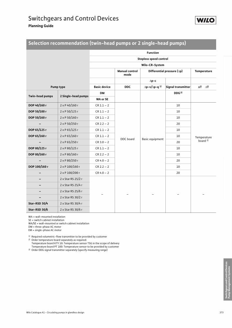
373
Switchgears and Control DevicesPlanning Guide
Selection recommendation (twin-head pumps or 2 single-head pumps)
Wilo Catalogue A1 - Circulating pumps in glandless design
Hea
tin
g, A
ir-c
on
dit
ion
ing
, C
oo
ling
Po
tab
le w
ater
cir
cula
tio
nSo
lar
ther
mal
Serv
ice/
Acc
esso
ries
, Sys
tem
sSw
itch
gear
s an
d C
ontr
ol D
evic
es
Pum
p M
anag
emen
t Sy
stem
s
DOP 40/160 r 2 x P 40/160 r CR 1.1 – 2
DDC board Basic equipment
10
Temperature board 2)
DOP 50/100 r 2 x P 50/125 r CR 1.1 – 2 10
DOP 50/160 r 2 x P 50/160 r CR 1.1 – 2 10
– 2 x P 50/250 r CR 2.2 – 2 20
DOP 65/125 r 2 x P 65/125 r CR 1.1 – 2 10
DOP 65/160 r 2 x P 65/160 r CR 1.1 – 2 10
– 2 x P 65/250 r CR 3.0 – 2 20
DOP 80/125 r 2 x P 80/125 r CR 1.1 – 2 10
DOP 80/160 r 2 x P 80/160 r CR 2.2 – 2 10
– 2 x P 80/250 r CR 4.0 – 2 20
DOP 100/160 r 2 x P 100/160 r CR 2.2 – 2 10
– 2 x P 100/200 r CR 4.0 – 2 20
– 2 x Star RS 25/2 r
– – – – –
– 2 x Star RS 25/4 r
– 2 x Star RS 25/6 r
– 2 x Star RS 30/2 r
Star-RSD 30/4 2 x Star RS 30/4 r
Star-RSD 30/6 2 x Star RS 30/6 r
Pump type
Function
Stepless speed control
Wilo-CR-System
Manual control mode
Differential pressure ( p) Temperature
p-c
Basic device DDC p-v/ p-q 1) Signal transmitter ±T T
Twin-head pumps 2 Single-head pumpsDM DDG3)
WA or SE
WA = wall-mounted installationSE = switch cabinet installationWA/SE = wall-mounted or switch cabinet installationDM = three-phase AC motorEM = single-phase AC motor
1) Required volumetric-flow transmitter to be provided by customer2) Order temperature board separately as required:
Temperature board KTY 10: Temperature sensor TSG in the scope of delivery Temperature board PT 100: Temperature sensor to be provided by customer
3) Order DDG signal transmitter separately (specify measuring range)
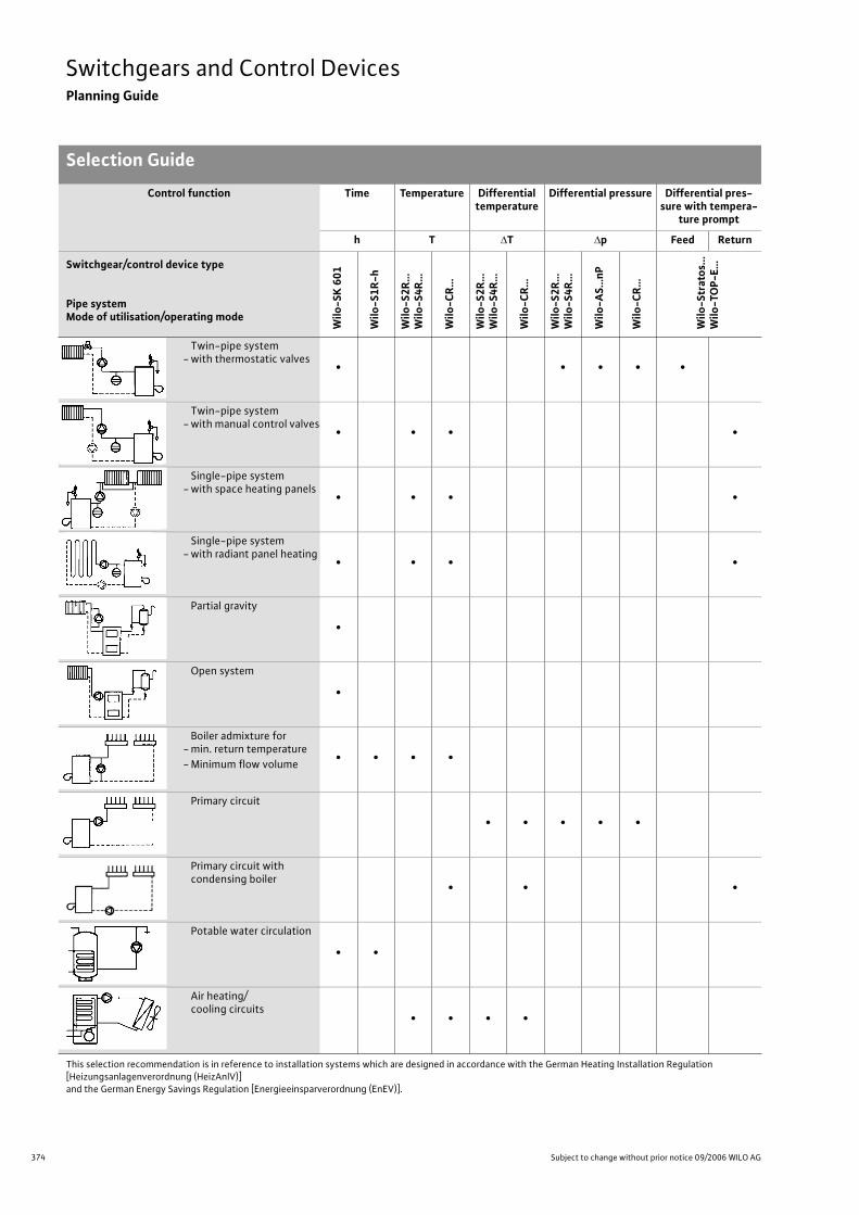
374 Subject to change without prior notice 09/2006 WILO AG
Switchgears and Control DevicesPlanning Guide
Selection Guide
This selection recommendation is in reference to installation systems which are designed in accordance with the German Heating Installation Regulation [Heizungsanlagenverordnung (HeizAnlV)]and the German Energy Savings Regulation [Energieeinsparverordnung (EnEV)].
Control function Time Temperature Differential temperature
Differential pressure Differential pres-sure with tempera-
ture prompt
h T T p Feed Return
Switchgear/control device type
Pipe systemMode of utilisation/operating mode
Wilo
-SK
60
1
Wilo
-S1
R-h
Wilo
-S2
R…
Wilo
-S4
R…
Wilo
-CR
…
Wilo
-S2
R…
W
ilo-S
4R
…
Wilo
-CR
…
Wilo
-S2
R…
W
ilo-S
4R
…
Wilo
-AS…
nP
Wilo
-CR
…
Wilo
-Str
ato
s...
Wilo
-TO
P-E
…
Twin-pipe system- with thermostatic valves
• • • • •
Twin-pipe system- with manual control valves
• • • •
Single-pipe system- with space heating panels
• • • •
Single-pipe system- with radiant panel heating
• • • •
Partial gravity
•
Open system
•
Boiler admixture for- min. return temperature
- Minimum flow volume• • • •
Primary circuit
• • • • •
Primary circuit withcondensing boiler
• • •
Potable water circulation
• •
Air heating/cooling circuits
• • • •
375
Switchgears and Control DevicesPlanning Guide
Wilo Catalogue A1 - Circulating pumps in glandless design
Hea
tin
g, A
ir-c
on
dit
ion
ing
, C
oo
ling
Po
tab
le w
ater
cir
cula
tio
nSo
lar
ther
mal
Serv
ice/
Acc
esso
ries
, Sys
tem
sSw
itch
gear
s an
d C
ontr
ol D
evic
es
Pum
p M
anag
emen
t Sy
stem
s
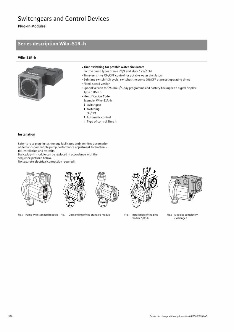
376 Subject to change without prior notice 09/2006 WILO AG
Switchgears and Control DevicesPlug-In Modules
Series description Wilo-S1R-h
Wilo-S1R-h
> Time switching for potable water circulatorsFor the pump types Star-Z 20/1 and Star-Z 25/2 EM
• Time-sensitive ON/OFF control for potable water circulators
• 24h time switch (14h cycle) switches the pump ON/OFF at preset operating times
• Fixed-speed version
• Special version for 24-hour/7-day programme and battery backup with digital display:
Type S1R-h S
> Identification Code:Example: Wilo-S1R-h
S switchgear
1 switching
On/Off
R Automatic control
h Type of control Time h
Installation
Safe-to-use plug-in technology facilitates problem-free automation of demand-compatible pump performance adjustment for both ini-tial installation and retrofits.Basic plug-in module can be replaced in accordance with the sequence pictured below.No separate electrical connection required!
Fig.: Pump with standard module Fig.: Dismantling of the standard module Fig.: Installation of the time module S1R-h
Fig.: Modules completely exchanged
Plug-In ModulesSeries descrip-tion Wilo-S1R-h
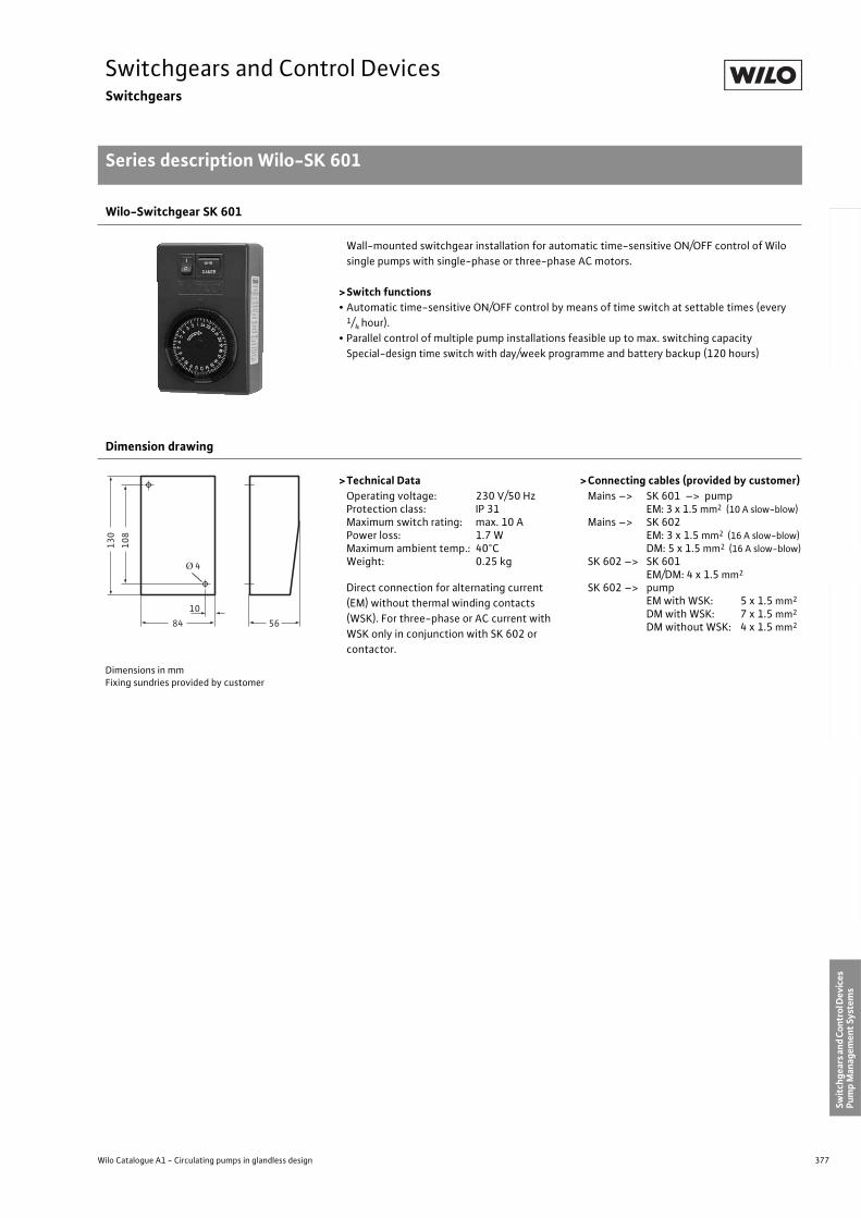
377
Switchgears and Control DevicesSwitchgears
Series description Wilo-SK 601
Wilo Catalogue A1 - Circulating pumps in glandless design
Hea
tin
g, A
ir-c
on
dit
ion
ing
, C
oo
ling
Po
tab
le w
ater
cir
cula
tio
nSo
lar
ther
mal
Serv
ice/
Acc
esso
ries
, Sys
tem
sSw
itch
gear
s an
d C
ontr
ol D
evic
es
Pum
p M
anag
emen
t Sy
stem
s
Wilo-Switchgear SK 601
Wall-mounted switchgear installation for automatic time-sensitive ON/OFF control of Wilo
single pumps with single-phase or three-phase AC motors.
>Switch functions• Automatic time-sensitive ON/OFF control by means of time switch at settable times (every
1/4 hour).
• Parallel control of multiple pump installations feasible up to max. switching capacity
Special-design time switch with day/week programme and battery backup (120 hours)
Dimension drawing
>Technical DataOperating voltage: 230 V/50 HzProtection class: IP 31Maximum switch rating: max. 10 APower loss: 1.7 WMaximum ambient temp.: 40°CWeight: 0.25 kg
Direct connection for alternating current
(EM) without thermal winding contacts
(WSK). For three-phase or AC current with
WSK only in conjunction with SK 602 or
contactor.
>Connecting cables (provided by customer)Mains –> SK 601 –> pump
EM: 3 x 1.5 mm2 (10 A slow-blow)Mains –> SK 602
EM: 3 x 1.5 mm2 (16 A slow-blow)DM: 5 x 1.5 mm2 (16 A slow-blow)
SK 602 –> SK 601EM/DM: 4 x 1.5 mm2
SK 602 –> pumpEM with WSK: 5 x 1.5 mm2
DM with WSK: 7 x 1.5 mm2
DM without WSK: 4 x 1.5 mm2
Dimensions in mmFixing sundries provided by customer
Switch-gearsSeries descrip-tion Wilo-SK 601
108
130
84 56
10
Ø 4
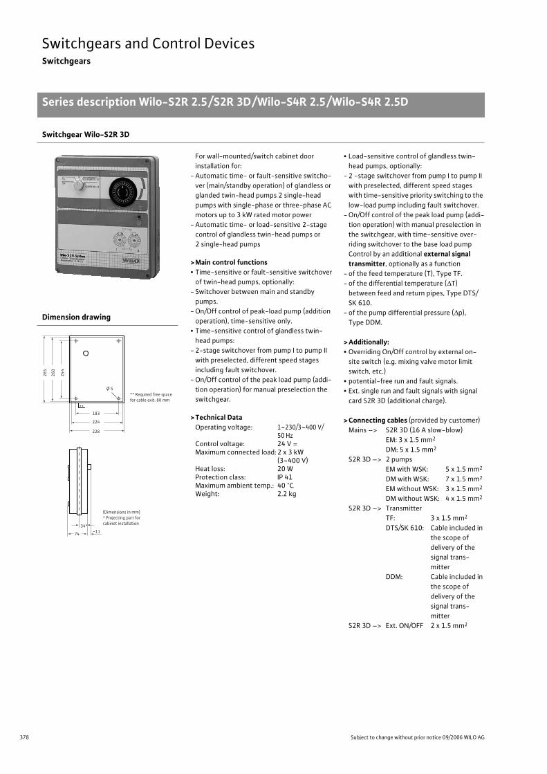
378 Subject to change without prior notice 09/2006 WILO AG
Switchgears and Control DevicesSwitchgears
Series description Wilo-S2R 2.5/S2R 3D/Wilo-S4R 2.5/Wilo-S4R 2.5D
Switchgear Wilo-S2R 3D
For wall-mounted/switch cabinet door
installation for:
- Automatic time- or fault-sensitive switcho-
ver (main/standby operation) of glandless or
glanded twin-head pumps 2 single-head
pumps with single-phase or three-phase AC
motors up to 3 kW rated motor power
- Automatic time- or load-sensitive 2-stage
control of glandless twin-head pumps or
2 single-head pumps
> Main control functions• Time-sensitive or fault-sensitive switchover
of twin-head pumps, optionally:
- Switchover between main and standby
pumps.
- On/Off control of peak-load pump (addition
operation), time-sensitive only.
• Time-sensitive control of glandless twin-
head pumps:
- 2-stage switchover from pump I to pump II
with preselected, different speed stages
including fault switchover.
- On/Off control of the peak load pump (addi-
tion operation) for manual preselection the
switchgear.
> Technical DataOperating voltage: 1~230/3~400 V/
50 HzControl voltage: 24 V =Maximum connected load: 2 x 3 kW
(3~400 V)Heat loss: 20 WProtection class: IP 41Maximum ambient temp.: 40 °CWeight: 2.2 kg
• Load-sensitive control of glandless twin-
head pumps, optionally:
- 2 -stage switchover from pump I to pump II
with preselected, different speed stages
with time-sensitive priority switching to the
low-load pump including fault switchover.
- On/Off control of the peak load pump (addi-
tion operation) with manual preselection in
the switchgear, with time-sensitive over-
riding switchover to the base load pump
Control by an additional external signal transmitter, optionally as a function
- of the feed temperature (T), Type TF.
- of the differential temperature ( T)
between feed and return pipes, Type DTS/
SK 610.
- of the pump differential pressure ( p),
Type DDM.
> Additionally:• Overriding On/Off control by external on-
site switch (e.g. mixing valve motor limit
switch, etc.)
• potential-free run and fault signals.
• Ext. single run and fault signals with signal
card S2R 3D (additional charge).
> Connecting cables (provided by customer)
Mains –> S2R 3D (16 A slow-blow)
EM: 3 x 1.5 mm2
DM: 5 x 1.5 mm2
S2R 3D –> 2 pumps
EM with WSK: 5 x 1.5 mm2
DM with WSK: 7 x 1.5 mm2
EM without WSK: 3 x 1.5 mm2
DM without WSK: 4 x 1.5 mm2
S2R 3D –> Transmitter
TF: 3 x 1.5 mm2
DTS/SK 610: Cable included in
the scope of
delivery of the
signal trans-
mitter
DDM: Cable included in
the scope of
delivery of the
signal trans-
mitter
S2R 3D –> Ext. ON/OFF 2 x 1.5 mm2
Dimension drawing
Series descrip-tion Wilo-S2R 2.5/S2R 3D/Wilo-S4R 2.5/Wilo-S4R 2.5D
24
4
26
0
26
5
228
224
183
74 ~11
34*
**
Ø 5
** Required free space
for cable exit: 80 mm
(Dimensions in mm)
* Projecting part for
cabinet installation
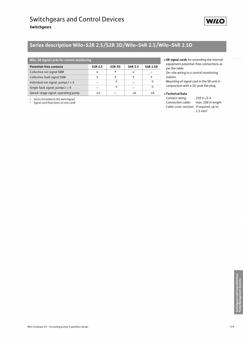
379
Switchgears and Control DevicesSwitchgears
Series description Wilo-S2R 2.5/S2R 3D/Wilo-S4R 2.5/Wilo-S4R 2.5D
Wilo Catalogue A1 - Circulating pumps in glandless design
Hea
tin
g, A
ir-c
on
dit
ion
ing
, C
oo
ling
Po
tab
le w
ater
cir
cula
tio
nSo
lar
ther
mal
Serv
ice/
Acc
esso
ries
, Sys
tem
sSw
itch
gear
s an
d C
ontr
ol D
evic
es
Pum
p M
anag
emen
t Sy
stem
s
Wilo-SR signal cards for remote monitoring > SR signal cards for extending the internal
equipment potential-free connections as
per the table.
On-site wiring to a central monitoring
station.
Mounting of signal card in the SR unit in
conjunction with a 10-pole flat plug.
> Technical DataContact rating: 250 V~/1 A
Connection cable: max. 100 m length
Cable cross-section: if required, up to
1.5 mm2
Potential-free contacts S2R 2.5 S2R 3D S4R 2.5 S4R 2.5D
Collective run signal SBM o • o –
Collective fault signal SSM • • • •Individual run signal, pumps I + II – o – o
Single fault signal, pumps I + II – o – o
Speed-stage signal, operating pump o2 – o4 o4
• Series (included in the switchgear)o Signal card (functions on one card)
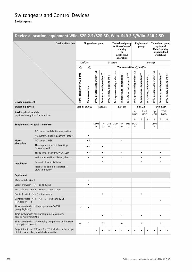
380 Subject to change without prior notice 09/2006 WILO AG
Switchgears and Control DevicesSwitchgears
Device allocation, equipment Wilo-S2R 2.5/S2R 3D, Wilo-S4R 2.5/Wilo-S4R 2.5D
Device allocation
Device equipment
Single-head pump Twin-head pumpoption of main/
standbyor
peak-load operation
Single-head pump
Twin-head pumpoption of
Main/standbyor peak-load
switching
On/Off 2-stage 4-stage
Time-sensitive and/or
Tim
e-se
nsi
tive
fo
r Z
-pu
mp
Tim
e-se
nsi
tive
Dif
f.-p
ress
ure
dep
end
ent
p
Tem
per
atu
re-d
epen
den
t T
Dif
f.-T
emp
.-d
epen
den
t T
Dif
f.-p
ress
ure
dep
end
ent
p
Tem
per
atu
re-d
epen
den
t T
Dif
f.-T
emp
.-d
epen
den
t T
Dif
f.-p
ress
ure
dep
end
ent
p
Tem
per
atu
re-d
epen
den
t T
Dif
f.-T
emp
.-d
epen
den
t T
Dif
f.-p
ress
ure
dep
end
ent
p
Tem
per
atu
re-d
epen
den
t T
Dif
f.-T
emp
.-d
epen
den
t T
Switching device S1R-h SK 601 S2R 2.5 S2R 3D S4R 2.5 S4R 2.5D
Auxiliary load module (optional – required for function)
pMOD
T TMOD
pMOD
T TMOD
o o o o o o
Supplementary signal transmitter DDMo
TFo
DTSo
DDMo
TFo
DTSo
DDMo
DDMo
Motorallocation
AC current with built-in capacitor •
AC current, blocking current-proof •
AC current, WSK • 1) •
Three-phase current, blocking current-proof
• 1) •
Three-phase current, WSK, SSM • 1) • • • •
Installation
Wall-mounted installation, direct • • • • •
Cabinet-door installation • • • •
Integrated pump installation – plug-in module
•
Equipment
Main switch 0 – 1 •
Selector switch – continuous •
Pre-selector switch Maximum speed stage
Control switch – 0 – Automatic • •
Control switch II – I – 0 – Standby I/II – Addition I + II
• •
Time switch with daily programme On/Off (every 1/4 hour)
• •
Time switch with daily programme Maximum/Min. or Automatic/Min.
• • • •
Time switch with daily/weekly programme and battery backup (120 hours)
o o o o o o
Setpoint adjuster 2) ( p – T – T) included in the scope of delivery auxiliary module/transmitter
• • • • • • • • • • • •
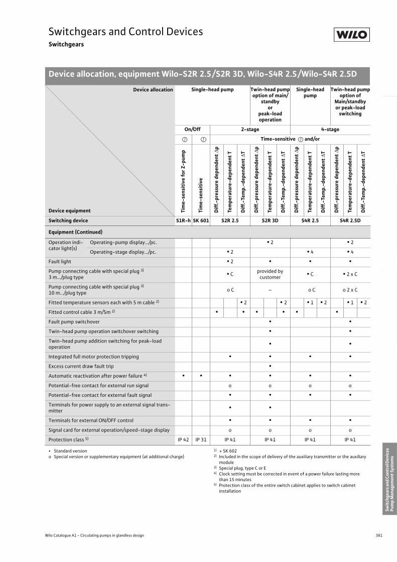
381
Switchgears and Control DevicesSwitchgears
Device allocation, equipment Wilo-S2R 2.5/S2R 3D, Wilo-S4R 2.5/Wilo-S4R 2.5D
Wilo Catalogue A1 - Circulating pumps in glandless design
Hea
tin
g, A
ir-c
on
dit
ion
ing
, C
oo
ling
Po
tab
le w
ater
cir
cula
tio
nSo
lar
ther
mal
Serv
ice/
Acc
esso
ries
, Sys
tem
sSw
itch
gear
s an
d C
ontr
ol D
evic
es
Pum
p M
anag
emen
t Sy
stem
s
Equipment (Continued)
Operation indi-cator light(s)
Operating-pump display…/pc. • 2 • 2
Operating-stage display…/pc. • 2 • 4 • 4
Fault light • 2 • • •
Pump connecting cable with special plug 3)
3 m.../plug type• C
provided by customer
• C • 2 x C
Pump connecting cable with special plug 3)
10 m.../plug type o C – o C o 2 x C
Fitted temperature sensors each with 5 m cable 2) • 2 • 2 • 1 • 2 • 1 • 2
Fitted control cable 3 m/5m 2) • • • • • •
Fault pump switchover • •
Twin-head pump operation switchover switching • •
Twin-head pump addition switching for peak-load operation
• •
Integrated full motor protection tripping • • • •
Excess current draw fault trip •
Automatic reactivation after power failure 4) • • • • • •
Potential-free contact for external run signal o o o o
Potential-free contact for external fault signal • • • •
Terminals for power supply to an external signal trans-mitter
• •
Terminals for external ON/OFF control • • • •
Signal card for external operation/speed-stage display o o o o
Protection class 5) IP 42 IP 31 IP 41 IP 41 IP 41 IP 41
• Standard versiono Special version or supplementary equipment (at additional charge)
1) + SK 6022) Included in the scope of delivery of the auxiliary transmitter or the auxiliary
module3) Special plug, type C or E4) Clock setting must be corrected in event of a power failure lasting more
than 15 minutes5) Protection class of the entire switch cabinet applies to switch cabinet
installation
Device allocation
Device equipment
Single-head pump Twin-head pumpoption of main/
standbyor
peak-load operation
Single-head pump
Twin-head pumpoption of
Main/standbyor peak-load
switching
On/Off 2-stage 4-stage
Time-sensitive and/or
Tim
e-se
nsi
tive
fo
r Z
-pu
mp
Tim
e-se
nsi
tive
Dif
f.-p
ress
ure
dep
end
ent
p
Tem
per
atu
re-d
epen
den
t T
Dif
f.-T
emp
.-d
epen
den
t T
Dif
f.-p
ress
ure
dep
end
ent
p
Tem
per
atu
re-d
epen
den
t T
Dif
f.-T
emp
.-d
epen
den
t T
Dif
f.-p
ress
ure
dep
end
ent
p
Tem
per
atu
re-d
epen
den
t T
Dif
f.-T
emp
.-d
epen
den
t T
Dif
f.-p
ress
ure
dep
end
ent
p
Tem
per
atu
re-d
epen
den
t T
Dif
f.-T
emp
.-d
epen
den
t T
Switching device S1R-h SK 601 S2R 2.5 S2R 3D S4R 2.5 S4R 2.5D
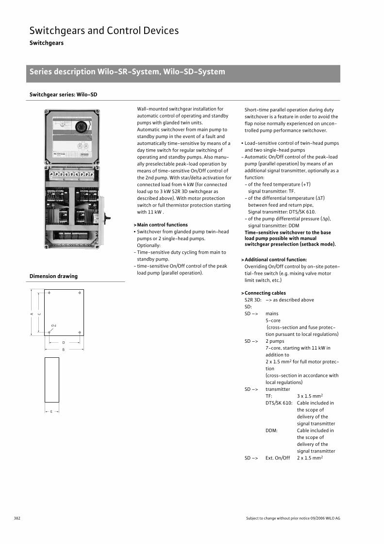
382 Subject to change without prior notice 09/2006 WILO AG
Switchgears and Control DevicesSwitchgears
Series description Wilo-SR-System, Wilo-SD-System
Switchgear series: Wilo-SD
Wall-mounted switchgear installation for
automatic control of operating and standby
pumps with glanded twin units.
Automatic switchover from main pump to
standby pump in the event of a fault and
automatically time-sensitive by means of a
day time switch for regular switching of
operating and standby pumps. Also manu-
ally preselectable peak-load operation by
means of time-sensitive On/Off control of
the 2nd pump. With star/delta activation for
connected load from 4 kW (for connected
load up to 3 kW S2R 3D switchgear as
described above). With motor protection
switch or full thermistor protection starting
with 11 kW .
> Main control functions• Switchover from glanded pump twin-head
pumps or 2 single-head pumps.
Optionally:
- Time-sensitive duty cycling from main to
standby pump.
- time-sensitive On/Off control of the peak
load pump (parallel operation).
Short-time parallel operation during duty
switchover is a feature in order to avoid the
flap noise normally experienced on uncon-
trolled pump performance switchover.
• Load-sensitive control of twin-head pumps
and two single-head pumps
- Automatic On/Off control of the peak-load
pump (parallel operation) by means of an
additional signal transmitter, optionally as a
function:
- of the feed temperature (+T)
signal transmitter: TF.
- of the differential temperature ( T)
between feed and return pipe,
Signal transmitter: DTS/SK 610.
- of the pump differential pressure ( p),
signal transmitter: DDM
Time-sensitive switchover to the base load pump possible with manual switchgear preselection (setback mode).
> Additional control function:Overriding On/Off control by on-site poten-
tial-free switch (e.g. mixing valve motor
limit switch, etc.)
> Connecting cablesS2R 3D: –> as described above
SD:
SD –> mains
5-core
(cross-section and fuse protec-
tion pursuant to local regulations)
SD –> 2 pumps
7-core, starting with 11 kW in
addition to
2 x 1.5 mm2 for full motor protec-
tion
(cross-section in accordance with
local regulations)
SD –> transmitter
TF: 3 x 1.5 mm2
DTS/SK 610: Cable included in
the scope of
delivery of the
signal transmitter
DDM: Cable included in
the scope of
delivery of the
signal transmitter
SD –> Ext. On/Off 2 x 1.5 mm2
Dimension drawing
Series descrip-tion Wilo-SR-Sys-tem, Wilo-SD-Sys-tem
CA
B
D
E
Ø d
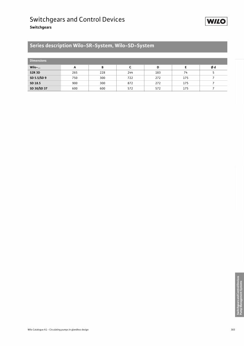
383
Switchgears and Control DevicesSwitchgears
Series description Wilo-SR-System, Wilo-SD-System
Wilo Catalogue A1 - Circulating pumps in glandless design
Hea
tin
g, A
ir-c
on
dit
ion
ing
, C
oo
ling
Po
tab
le w
ater
cir
cula
tio
nSo
lar
ther
mal
Serv
ice/
Acc
esso
ries
, Sys
tem
sSw
itch
gear
s an
d C
ontr
ol D
evic
es
Pum
p M
anag
emen
t Sy
stem
s
Dimensions
Wilo-... A B C D E Ø d
S2R 3D 265 228 244 183 74 5
SD 5.5/SD 9 750 300 722 272 175 7
SD 18.5 900 300 872 272 175 7
SD 30/SD 37 600 600 572 572 175 7
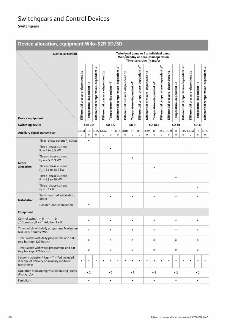
384 Subject to change without prior notice 09/2006 WILO AG
Switchgears and Control DevicesSwitchgears
Device allocation, equipment Wilo-S2R 3D/SD
Device allocation
Device equipment
Twin-head pump or 2 x individual pumpMain/standby or peak-load operation
Time-sensitive and/or
Dif
fere
nti
al p
ress
ure
-dep
end
ent
p
Tem
per
atu
re-d
epen
den
t +
T
Dif
fere
nti
al t
emp
erat
ure
-dep
end
ent
T
Dif
fere
nti
al p
ress
ure
-dep
end
ent
p
Tem
per
atu
re-d
epen
den
t +
T
Dif
fere
nti
al t
emp
erat
ure
-dep
end
ent
T
Dif
fere
nti
al p
ress
ure
-dep
end
ent
p
Tem
per
atu
re-d
epen
den
t +
T
Dif
fere
nti
al t
emp
erat
ure
-dep
end
ent
T
Dif
fere
nti
al p
ress
ure
-dep
end
ent
p
Tem
per
atu
re-d
epen
den
t +
T
Dif
fere
nti
al t
emp
erat
ure
-dep
end
ent
T
Dif
fere
nti
al p
ress
ure
-dep
end
ent
p
Tem
per
atu
re-d
epen
den
t +
T
Dif
fere
nti
al t
emp
erat
ure
-dep
end
ent
T
Dif
fere
nti
al p
ress
ure
-dep
end
ent
p
Tem
per
atu
re-d
epen
den
t +
T
Dif
fere
nti
al t
emp
erat
ure
-dep
end
ent
T
Switching device S2R 3D SD 5.5 SD 9 SD 18.5 SD 30 SD 37
Auxiliary signal transmitterDDM
oTFo
DTSo
DDMo
TFo
DTSo
DDMo
TFo
DTSo
DDMo
TFo
DTSo
DDMo
TFo
DTSo
DDMo
TFo
DTSo
Motorallocation
Three-phase current P2 3 kW •
Three-phase current P2 = 4 to 5.5 kW
•
Three-phase current P2 = 7.5 to 9 kW
•
Three-phase current P2 = 11 to 18.5 kW
•
Three-phase current P2 = 22 to 30 kW
•
Three-phase current P2 = 37 kW
•
Installation
Wall-mounted installation, direct
• • • • •
Cabinet-door installation •
Equipment
Control switch II – I – 0 – Standby I/II – Addition I + II
• • • • • •
Time switch with daily programme Maximum/Min. or Automatic/Min.
• • • • • •
Time switch with daily programme and bat-tery backup (120 hours)
o o o o o o
Time switch with week programme and bat-tery backup (120 hours)
o o o o o o
Setpoint adjuster 3) ( p – T – T ) included is scope of delivery of auxiliary module/transmitter
• • • • • • • • • • • • • • • • • •
Operation indicator light(s), operating-pump display…/pc.
• 2 • 2 • 2 • 2 • 2 • 2
Fault light • • • • • •
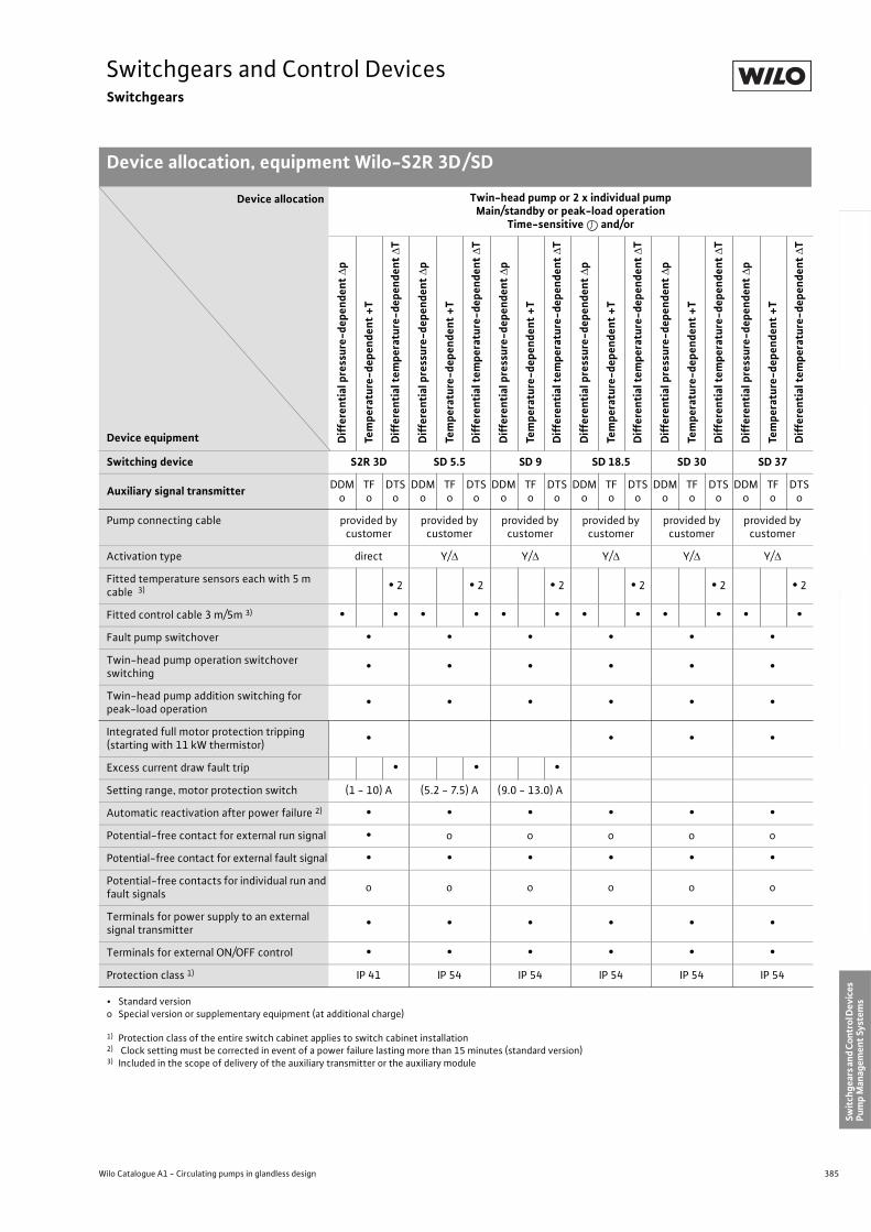
385
Switchgears and Control DevicesSwitchgears
Device allocation, equipment Wilo-S2R 3D/SD
Wilo Catalogue A1 - Circulating pumps in glandless design
Hea
tin
g, A
ir-c
on
dit
ion
ing
, C
oo
ling
Po
tab
le w
ater
cir
cula
tio
nSo
lar
ther
mal
Serv
ice/
Acc
esso
ries
, Sys
tem
sSw
itch
gear
s an
d C
ontr
ol D
evic
es
Pum
p M
anag
emen
t Sy
stem
s
Pump connecting cable provided by customer
provided by customer
provided by customer
provided by customer
provided by customer
provided by customer
Activation type direct Y/ Y/ Y/ Y/ Y/
Fitted temperature sensors each with 5 m cable 3) • 2 • 2 • 2 • 2 • 2 • 2
Fitted control cable 3 m/5m 3) • • • • • • • • • • • •
Fault pump switchover • • • • • •
Twin-head pump operation switchover switching
• • • • • •
Twin-head pump addition switching for peak-load operation
• • • • • •
Integrated full motor protection tripping(starting with 11 kW thermistor)
• • • •
Excess current draw fault trip • • •
Setting range, motor protection switch (1 - 10) A (5.2 - 7.5) A (9.0 - 13.0) A
Automatic reactivation after power failure 2) • • • • • •
Potential-free contact for external run signal • o o o o o
Potential-free contact for external fault signal • • • • • •
Potential-free contacts for individual run and fault signals
o o o o o o
Terminals for power supply to an external signal transmitter
• • • • • •
Terminals for external ON/OFF control • • • • • •
Protection class 1) IP 41 IP 54 IP 54 IP 54 IP 54 IP 54
• Standard versiono Special version or supplementary equipment (at additional charge)
1) Protection class of the entire switch cabinet applies to switch cabinet installation2) Clock setting must be corrected in event of a power failure lasting more than 15 minutes (standard version)3) Included in the scope of delivery of the auxiliary transmitter or the auxiliary module
Device allocation
Device equipment
Twin-head pump or 2 x individual pumpMain/standby or peak-load operation
Time-sensitive and/or
Dif
fere
nti
al p
ress
ure
-dep
end
ent
p
Tem
per
atu
re-d
epen
den
t +
T
Dif
fere
nti
al t
emp
erat
ure
-dep
end
ent
T
Dif
fere
nti
al p
ress
ure
-dep
end
ent
p
Tem
per
atu
re-d
epen
den
t +
T
Dif
fere
nti
al t
emp
erat
ure
-dep
end
ent
T
Dif
fere
nti
al p
ress
ure
-dep
end
ent
p
Tem
per
atu
re-d
epen
den
t +
T
Dif
fere
nti
al t
emp
erat
ure
-dep
end
ent
T
Dif
fere
nti
al p
ress
ure
-dep
end
ent
p
Tem
per
atu
re-d
epen
den
t +
T
Dif
fere
nti
al t
emp
erat
ure
-dep
end
ent
T
Dif
fere
nti
al p
ress
ure
-dep
end
ent
p
Tem
per
atu
re-d
epen
den
t +
T
Dif
fere
nti
al t
emp
erat
ure
-dep
end
ent
T
Dif
fere
nti
al p
ress
ure
-dep
end
ent
p
Tem
per
atu
re-d
epen
den
t +
T
Dif
fere
nti
al t
emp
erat
ure
-dep
end
ent
T
Switching device S2R 3D SD 5.5 SD 9 SD 18.5 SD 30 SD 37
Auxiliary signal transmitterDDM
oTFo
DTSo
DDMo
TFo
DTSo
DDMo
TFo
DTSo
DDMo
TFo
DTSo
DDMo
TFo
DTSo
DDMo
TFo
DTSo
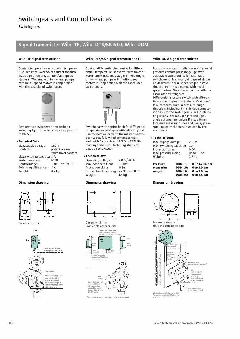
386 Subject to change without prior notice 09/2006 WILO AG
Switchgears and Control DevicesSwitchgears
Signal transmitter Wilo-TF, Wilo-DTS/SK 610, Wilo-DDM
Wilo-TF signal transmitter Wilo-DTS/SK signal transmitter 610 Wilo-DDM signal transmitter
Contact temperature sensor with tempera-ture-sensitive switchover contact for auto-matic alteration of Maximum/Min. speed stages in Wilo single or twin-head pumps with multi-speed motors in conjunction with the associated switchgears.
Contact differential thermostat for differ-ential-temperature-sensitive switchover of Maximum/Min. speeds stages in Wilo single or twin-head pumps with multi-speed motors in conjunction with the associated switchgears.
For wall-mounted installation as differential pressure contact pressure gauge. with adjustable switchpoints for automatic switchover of Maximum/Min. speed stages or Maximum to Min. speed stages in Wilo single or twin-head pumps with multi-speed motors. Only in conjunction with the associated switchgears.Differential-pressure switch with differen-tial-pressure gauge, adjustable Maximum/Min. contacts, built-in pressure-surge throttlers, including 5 m shielded connect-ing cable to the switchgear, 2 pcs. cutting-ring unions DIN 3862 ø 6 mm and 2 pcs. angle cutting-ring unions R 1 8 x ø 6 mm (pressure measuring lines and 3-way pres-sure-gauge cocks to be provided by the customer).
> Technical DataMax. supply voltage: 250 VMax. switching capacity: 1 AProtection class: IP 54Max. pressure rating: up to 16 barWeight: 1.7 kg
Pressure DDM 6: 0 up to 0.6 barmeasuring DDM 10: 0 to 1.0 barranges: DDM 16: 0 to 1.6 bar
DDM 25: 0 to 2.5 bar
Temperature switch with setting knob including 1 pc. fastening straps to pipes up to DN 50.
>Technical DataMax. supply voltage: 250 VContacts: potential-free
switchover contactMax. switching capacity: 3 AProtection class: IP 30Control range: +30 °C to +90 °CSwitching difference: 5 KWeight: 0.2 kg
Switchgear with setting knob for differential temperature switchgear with adjusting dial, 3 m connection cable to the master switch-gear, 2 pcs. fully wired contact sensors, each with 5 m cable and FEED or RETURN markings and 4 pcs. fastening straps for pipes up to DN 100.
> Technical DataOperating voltage: 230 V/50 HzMax. connected load: 0.1 kWProtection class: IP 54Differential-temp. range: +4 °C to +90 °CWeight: 1.4 kg
Dimension drawing Dimension drawing Dimension drawing
Dimensions in mm Dimensions in mmFixation elements on-site
Dimensions in mmFixation elements on-site
Signal transmit-ter Wilo-TF, Wilo-DTS/SK 610, Wilo-DDM
Wilo pump
Connection cable foruse with S2R 2.5:with special plug included in scope ofdelivery; for use withS2R 3D: onsite
?
Cable connection to switch gear 3 x 1,5 mm2
Return
Returnsensor
?
Feed
Feedsensor
Wilopump
Connection cable foruse with S2R 2.5:with special plug included in scope ofdelivery; for use withS2R 3D: onsite
1)Included in scope of delivery of the signal transmitter
Feed sensorcable1)
Return sensorcable1)
3 m cable forconnection to switch gear1) 6 x 0,75 mm.
DTS/SK 610 controllerShown as external sensor (iT)use together with Wilo switch gear
DDM
:
Pressuremeasuring lines6 x 1 mm Cu(onsite)
Wilosingle-head pump
Motor cable withspecial plug(scope of delivery ofthe Wilo switch gear)
1)Included in scope of delivery of the DDMPressure measuring lines and the three-way-gauge cocks must be available onsite
Elbow taper bush typepipe unionR 1"x ø 6 mm1)
Wlbow taper bushtype pipe unionR 1" x ø 6 mm1)
2 pcs. taper bushtype screwedunionsR 1" x ø 6 mm1)
5 m
shie
lded
cab
le 3
x 0
,75
mm
2 for c
onne
ctio
n to
switc
h ge
ars1
)
Shie
lded
cab
le fo
r ons
ite e
xten
sion
:to
100
m 3
x 1
,5 m
m2
; to
250
m 2
x 0
,75
mm
2
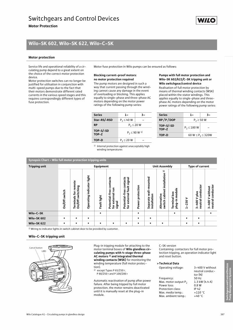
387
Switchgears and Control DevicesMotor Protection
Wilo-SK 602, Wilo-SK 622, Wilo-C-SK
Wilo Catalogue A1 - Circulating pumps in glandless design
Hea
tin
g, A
ir-c
on
dit
ion
ing
, C
oo
ling
Po
tab
le w
ater
cir
cula
tio
nSo
lar
ther
mal
Serv
ice/
Acc
esso
ries
, Sys
tem
sSw
itch
gear
s an
d C
ontr
ol D
evic
es
Pum
p M
anag
emen
t Sy
stem
s1) Wiring to indicator lights in switch cabinet door to be provided by customer.
Motor protection
Service life and operational reliability of a cir-culating pump depend to a great extent on the choice of the correct motor protection device.Motor protection switches can no longer be justified for utilisation in conjunction with multi-speed pumps due to the fact that their motors demonstrate different rated currents in the various speed stages and this requires correspondingly different types of fuse protection.
Motor fuse protection in Wilo pumps can be ensured as follows:
Blocking current-proof motors:no motor protection requiredThe pump motors are designed in such a way that current passing through the wind-ing cannot cause any damage in the event of overloading or blocking. This applies equally to single-phase and three-phase AC motors depending on the motor power ratings of the following pump series:
Pumps with full motor protection and Wilo-SK 602/622/C-SK tripping unit or Wilo switchgear/control deviceRealisation of full motor protection by means of thermal winding contacts (WSK) placed within the stator windings. This applies equally to single-phase and three-phase AC motors depending on the motor power ratings of the following pump series:
Series 1~ 3~ Series 1~ 3~
Star-RS/-RSD P2 40 W – RP / P / DOP P2 50 W
RP P2 20 W TOP-S/-SDTOP-Z
P2 180 W –TOP-S/-SDTOP-Z
P2 90 W 1)
TOP-D 60 W P2 320W
TOP-D P2 20 W –
1) Internal protection against unacceptably highwinding temperatures
Synopsis Chart - Wilo full motor protection tripping units
Tripping unit Equipment Unit Assembly Type of current
On
/Off
sw
itch
Term
inal
s fo
r re
mo
teO
n/O
ff s
wit
chin
g
Op
erat
ing
ind
icat
or
ligh
t
Fau
lt li
gh
t
Po
ten
tial
-fre
e co
nta
cts
for
exte
rnal
ru
nsi
gn
al
Po
ten
tial
-fre
e co
nta
cts
for
exte
rnal
fau
lt s
ign
al
Po
wer
pro
tect
ion
Sep
arat
e w
all-
mo
un
ted
in
stal
lati
on
Alt
ern
ativ
e sw
itch
cab
inet
inst
alla
tio
n 1
)
Term
inal
box
plu
g-i
n m
od
ule
1~
23
0 V
3~
40
0 V
plu
s n
eutr
al c
on
du
cto
r
3~
40
0 V
wit
ho
ut
neu
tral
co
nd
uct
or
Wilo-C-SK • • • •Wilo-SK 602 • • • • • • •Wilo-SK 622 • • • • • • • • • • •
Wilo-C-SK tripping unit
Plug-in tripping module for attaching to the motor terminal boxes of Wilo glandless cir-culating pumps with 4-stage three-phase AC motors 1) and integrated thermal winding contacts (WSK) for monitoring the winding temperature (full motor protec-tion).1) except Types P 65/250 r, P 80/250 r and P 100/200 r
Automatic reactivation of pump after power failure. After being tripped by full motor protection, the motor remains deactivated until it is manually reset at the plug-in module.
C-SK versionContaining: contactors for full motor pro-tection tripping, an operation indicator light and reset button.
>Technical DataOperating voltage: 3~400 V without
neutral conduc-tor (N)
Frequency: 50 HzMax. motor output P2 1.3 kW (4.4 A)Power loss: 0.8 WProtection class: IP 42Max. media temp.: +110 °CMax. ambient temp.: +40 °C
Motor Pro-tectionWilo-SK 602, Wilo-SK 622, Wilo-C-SK
Cancel button
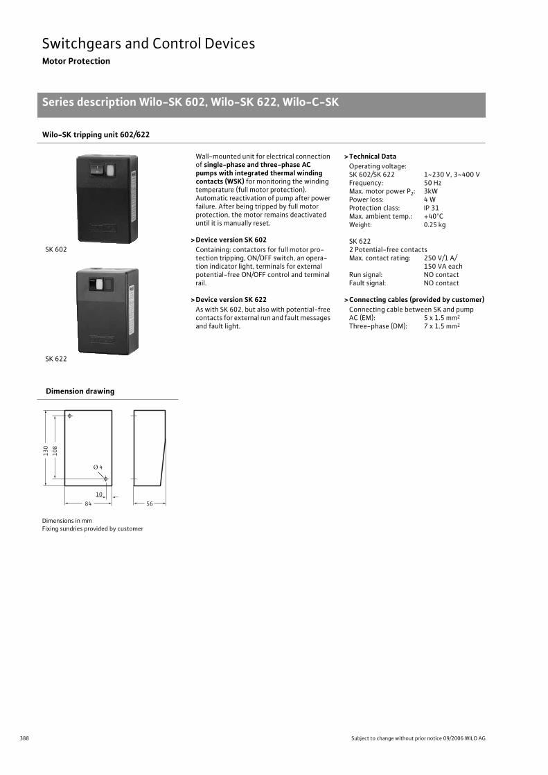
388 Subject to change without prior notice 09/2006 WILO AG
Switchgears and Control DevicesMotor Protection
Series description Wilo-SK 602, Wilo-SK 622, Wilo-C-SK
Wilo-SK tripping unit 602/622
SK 602
SK 622
Wall-mounted unit for electrical connection of single-phase and three-phase AC pumps with integrated thermal winding contacts (WSK) for monitoring the winding temperature (full motor protection).Automatic reactivation of pump after power failure. After being tripped by full motor protection, the motor remains deactivated until it is manually reset.
> Device version SK 602Containing: contactors for full motor pro-tection tripping, ON/OFF switch, an opera-tion indicator light, terminals for external potential-free ON/OFF control and terminal rail.
> Device version SK 622As with SK 602, but also with potential-free contacts for external run and fault messages and fault light.
> Technical DataOperating voltage:SK 602/SK 622 1~230 V, 3~400 VFrequency: 50 HzMax. motor power P2: 3kWPower loss: 4 WProtection class: IP 31Max. ambient temp.: +40°CWeight: 0.25 kg
SK 6222 Potential-free contactsMax. contact rating: 250 V/1 A/
150 VA eachRun signal: NO contactFault signal: NO contact
> Connecting cables (provided by customer)Connecting cable between SK and pumpAC (EM): 5 x 1.5 mm2
Three-phase (DM): 7 x 1.5 mm2
Dimension drawing
Dimensions in mmFixing sundries provided by customer
Series descrip-tion Wilo-SK 602, Wilo-SK 622, Wilo-C-SK
108
130
84 56
10
Ø 4
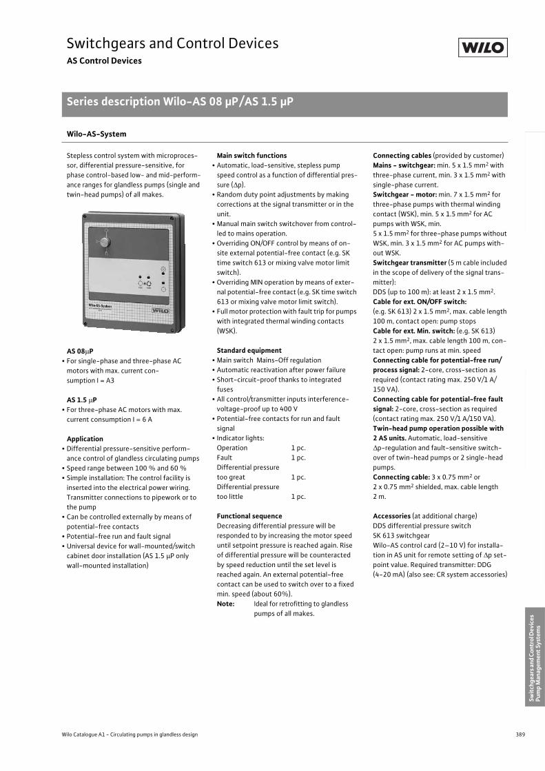
389
Switchgears and Control DevicesAS Control Devices
Series description Wilo-AS 08 µP/AS 1.5 µP
Wilo Catalogue A1 - Circulating pumps in glandless design
Hea
tin
g, A
ir-c
on
dit
ion
ing
, C
oo
ling
Po
tab
le w
ater
cir
cula
tio
nSo
lar
ther
mal
Serv
ice/
Acc
esso
ries
, Sys
tem
sSw
itch
gear
s an
d C
ontr
ol D
evic
es
Pum
p M
anag
emen
t Sy
stem
s
Wilo-AS-System
Stepless control system with microproces-
sor, differential pressure-sensitive, for
phase control-based low- and mid-perform-
ance ranges for glandless pumps (single and
twin-head pumps) of all makes.
AS 08 P• For single-phase and three-phase AC
motors with max. current con-
sumption I = A3
AS 1.5 P• For three-phase AC motors with max.
current consumption I = 6 A
Application• Differential pressure-sensitive perform-
ance control of glandless circulating pumps
• Speed range between 100 % and 60 %
• Simple installation: The control facility is
inserted into the electrical power wiring.
Transmitter connections to pipework or to
the pump
• Can be controlled externally by means of
potential-free contacts
• Potential-free run and fault signal
• Universal device for wall-mounted/switch
cabinet door installation (AS 1.5 P only
wall-mounted installation)
Main switch functions• Automatic, load-sensitive, stepless pump
speed control as a function of differential pres-
sure ( p).
• Random duty point adjustments by making
corrections at the signal transmitter or in the
unit.
• Manual main switch switchover from control-
led to mains operation.
• Overriding ON/OFF control by means of on-
site external potential-free contact (e.g. SK
time switch 613 or mixing valve motor limit
switch).
• Overriding MIN operation by means of exter-
nal potential-free contact (e.g. SK time switch
613 or mixing valve motor limit switch).
• Full motor protection with fault trip for pumps
with integrated thermal winding contacts
(WSK).
Standard equipment• Main switch Mains-Off regulation
• Automatic reactivation after power failure
• Short-circuit-proof thanks to integrated
fuses
• All control/transmitter inputs interference-
voltage-proof up to 400 V
• Potential-free contacts for run and fault
signal
• Indicator lights:
Operation 1 pc.
Fault 1 pc.
Differential pressure
too great 1 pc.
Differential pressure
too little 1 pc.
Functional sequenceDecreasing differential pressure will be
responded to by increasing the motor speed
until setpoint pressure is reached again. Rise
of differential pressure will be counteracted
by speed reduction until the set level is
reached again. An external potential-free
contact can be used to switch over to a fixed
min. speed (about 60%).
Note: Ideal for retrofitting to glandless
pumps of all makes.
Connecting cables (provided by customer)
Mains - switchgear: min. 5 x 1.5 mm2 with
three-phase current, min. 3 x 1.5 mm2 with
single-phase current.
Switchgear - motor: min. 7 x 1.5 mm2 for
three-phase pumps with thermal winding
contact (WSK), min. 5 x 1.5 mm2 for AC
pumps with WSK, min.
5 x 1.5 mm2 for three-phase pumps without
WSK, min. 3 x 1.5 mm2 for AC pumps with-
out WSK.
Switchgear transmitter (5 m cable included
in the scope of delivery of the signal trans-
mitter):
DDS (up to 100 m): at least 2 x 1.5 mm2.
Cable for ext. ON/OFF switch:(e.g. SK 613) 2 x 1.5 mm2, max. cable length
100 m, contact open: pump stops
Cable for ext. Min. switch: (e.g. SK 613)
2 x 1.5 mm2, max. cable length 100 m, con-
tact open: pump runs at min. speed
Connecting cable for potential-free run/process signal: 2-core, cross-section as
required (contact rating max. 250 V/1 A/
150 VA).
Connecting cable for potential-free fault signal: 2-core, cross-section as required
(contact rating max. 250 V/1 A/150 VA).
Twin-head pump operation possible with 2 AS units. Automatic, load-sensitive
p-regulation and fault-sensitive switch-
over of twin-head pumps or 2 single-head
pumps.
Connecting cable: 3 x 0.75 mm2 or
2 x 0.75 mm2 shielded, max. cable length
2 m.
Accessories (at additional charge)
DDS differential pressure switch
SK 613 switchgear
Wilo-AS control card (2–10 V) for installa-
tion in AS unit for remote setting of p set-
point value. Required transmitter: DDG
(4-20 mA) (also see: CR system accessories)
AS Control DevicesSeries descrip-tion Wilo-AS 08 µP/AS 1.5 µP
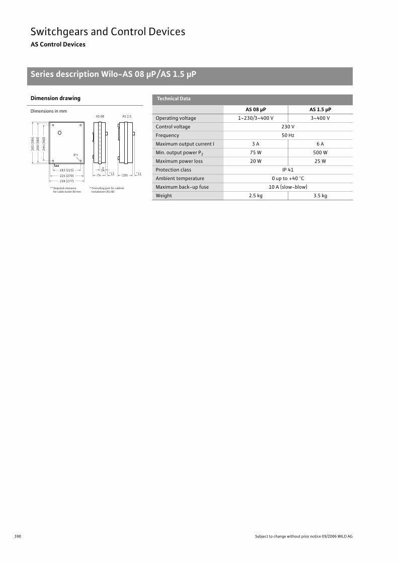
390 Subject to change without prior notice 09/2006 WILO AG
Switchgears and Control DevicesAS Control Devices
Series description Wilo-AS 08 µP/AS 1.5 µP
Dimension drawing Technical Data
Dimensions in mm AS 08 µP AS 1.5 µP
Operating voltage 1~230/3~400 V 3~400 V
Control voltage 230 V
Frequency 50 Hz
Maximum output current I 3 A 6 A
Min. output power P2 75 W 500 W
Maximum power loss 20 W 25 W
Protection class IP 41
Ambient temperature 0 up to +40 °C
Maximum back-up fuse 10 A (slow-blow)
Weight 2.5 kg 3.5 kg
244
(360
)
260
(380
)
265
(384
)
228 (277)
224 (270)
183 (223)
74 ~1134
***
Ø 5
** Required clearance for cable outlet 80 mm
* Protruding part for cabinet installation (AS 08)
105 ~11
AS 08 AS 1.5
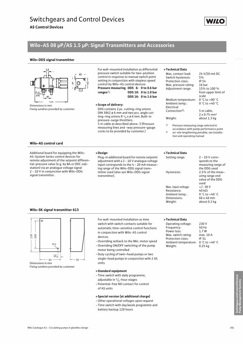
391
Switchgears and Control DevicesAS Control Devices
Wilo-AS 08 µP/AS 1.5 µP: Signal Transmitters and Accessories
Wilo Catalogue A1 - Circulating pumps in glandless design
Hea
tin
g, A
ir-c
on
dit
ion
ing
, C
oo
ling
Po
tab
le w
ater
cir
cula
tio
nSo
lar
ther
mal
Serv
ice/
Acc
esso
ries
, Sys
tem
sSw
itch
gear
s an
d C
ontr
ol D
evic
es
Pum
p M
anag
emen
t Sy
stem
s
Wilo-DDS signal transmitter
Dimensions in mmFixing sundries provided by customer
For wall-mounted installation as differential pressure switch suitable for two-position control in response to manual switch point setting in conjunction with stepless speed control by Wilo-AS control devices:Pressure measuring DDS 6: 0 to 0.6 barranges1): DDS 10: 0 to 1.0 bar
DDS 16: 0 to 1.6 bar
>Scope of delivery:DDS contains 2 pc. cutting-ring unions DIN 3862 ø 6 mm and two pcs. angle cut-ting-ring unions R 1 8 x ø 6 mm. Built-in pressure-surge throttlers. 5 m cable as described above. 3 (Pressure measuring lines and -way pressure-gauge cocks to be provided by customer.)
>Technical DataMax. contact load: 24 V/20 mA DCSwitch hysteresis: 5%Protection class: IP 54Max. pressure rating: 16 barAdjustment range: 15% to 100 %
from upper limit of scale
Medium temperature: 0 °C to +80 °CAmbient temp.: 0 °C to +40 °CElectrical Connection2): 5 m cable,
2 x 0.75 mm2
Weight: about 1.3 kg
1) Pressure measuring range selected in accordance with pump performance point
2) on-site lengthening possible; see Installa-tion and operating manual
Wilo-AS control card
Additional board for equipping the Wilo-AS-System Series control devices for remote adjustment of the setpoint differen-tial-pressure value (e.g. by BA or DDC sub-station) via an analogue voltage signal 2 - 10 V in conjunction with Wilo-DDG signal transmitter.
>DesignPlug-in additional board for remote setpoint adjustment with a 2 - 10 V analogue voltage input corresponds to the 4 - 20 mA measur-ing range of the Wilo-DDG signal trans-mitter used (also see Wilo-DDG signal transmitter).
>Technical DataSetting range: 2 - 10 V corre-
sponds to the measuring range of the DDG used
Hysteresis: 2.5% of the meas-uring range end value of the DDG used
Max. input voltage: +/- 30 VResistance: 40 kAmbient temp.: 0 °C to +40 °CDimensions: 68 x 48 mmWeight: about 0.2 kg
Wilo-SK signal transmitter 613
Dimensions in mmFixing sundries provided by customer
For wall-mounted installation as time
switch with switch contacts suitable for
automatic time-sensitive control functions
in conjunction with Wilo-AS control
devices.
- Overriding setback to the Min. motor speed
- Overriding ON/OFF switching of the pump
motor being controlled
- Duty cycling of twin-head pumps or two
single-head pumps in conjunction with 2 AS
units.
>Standard equipment- Time switch with daily programme,
adjustable in 1/4-hour stages
- Potential-free NO contact for control
of AS units
>Special version (at additional charge)- Other operational voltages upon request
- Time switch with day/week programme and
battery backup 120 hours
>Technical DataOperating voltage: 230 VFrequency: 50 HzPower loss: 1.7 WMax. switch rating: max. 10 AProtection class: IP 31Ambient temperature: 0 °C to +40 °CWeight: 0.25 kg
Wilo-AS 08 µP/AS 1.5 µP: Signal Transmit-ters and Accesso-ries
108
130
84 56
10
Ø 4
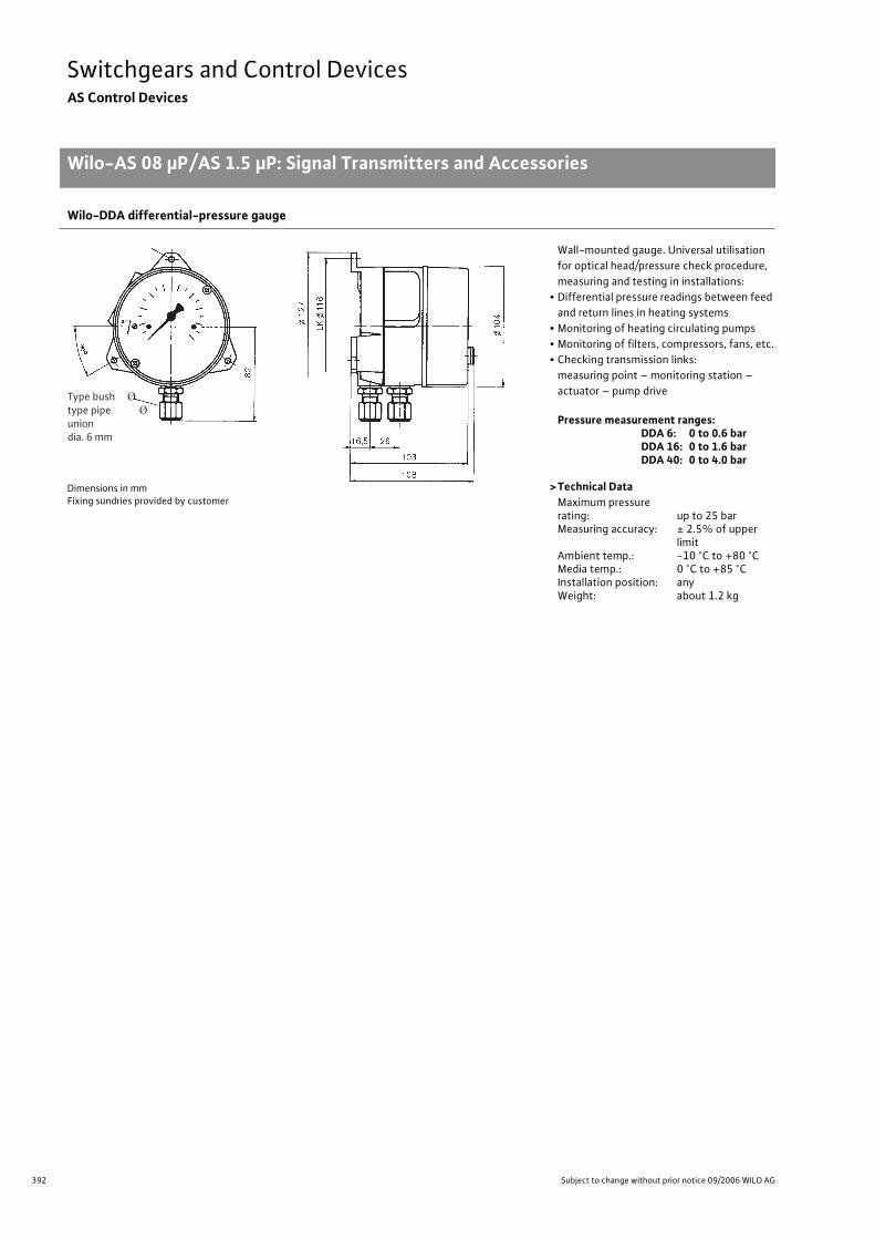
392 Subject to change without prior notice 09/2006 WILO AG
Switchgears and Control DevicesAS Control Devices
Wilo-AS 08 µP/AS 1.5 µP: Signal Transmitters and Accessories
Wilo-DDA differential-pressure gauge
Dimensions in mmFixing sundries provided by customer
Wall-mounted gauge. Universal utilisation
for optical head/pressure check procedure,
measuring and testing in installations:
• Differential pressure readings between feed
and return lines in heating systems
• Monitoring of heating circulating pumps
• Monitoring of filters, compressors, fans, etc.
• Checking transmission links:
measuring point – monitoring station –
actuator – pump drive
Pressure measurement ranges:DDA 6: 0 to 0.6 barDDA 16: 0 to 1.6 barDDA 40: 0 to 4.0 bar
> Technical DataMaximum pressure rating: up to 25 barMeasuring accuracy: ± 2.5% of upper
limitAmbient temp.: -10 °C to +80 °CMedia temp.: 0 °C to +85 °CInstallation position: anyWeight: about 1.2 kg
Type bushtype pipeuniondia. 6 mm
Ø
Ø
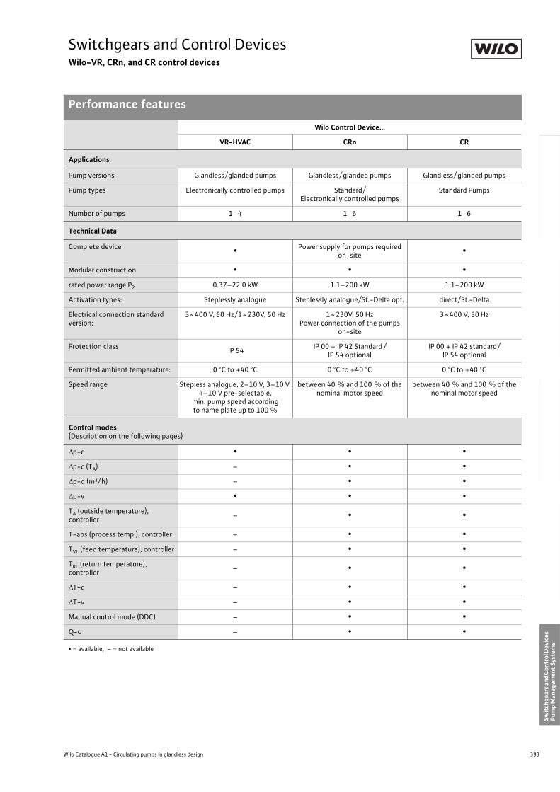
393
Switchgears and Control DevicesWilo-VR, CRn, and CR control devices
Performance features
Wilo Catalogue A1 - Circulating pumps in glandless design
Hea
tin
g, A
ir-c
on
dit
ion
ing
, C
oo
ling
Po
tab
le w
ater
cir
cula
tio
nSo
lar
ther
mal
Serv
ice/
Acc
esso
ries
, Sys
tem
sSw
itch
gear
s an
d C
ontr
ol D
evic
es
Pum
p M
anag
emen
t Sy
stem
s
Wilo Control Device…
VR-HVAC CRn CR
Applications
Pump versions Glandless/glanded pumps Glandless/ glanded pumps Glandless/ glanded pumps
Pump types Electronically controlled pumps Standard/Electronically controlled pumps
Standard Pumps
Number of pumps 1–4 1–6 1–6
Technical Data
Complete device • Power supply for pumps required on-site
•
Modular construction • • •
rated power range P2 0.37–22.0 kW 1.1–200 kW 1.1–200 kW
Activation types: Steplessly analogue Steplessly analogue/St.-Delta opt. direct/St.-Delta
Electrical connection standard version:
3~400 V, 50 Hz/1~230V, 50 Hz 1~230V, 50 HzPower connection of the pumps
on-site
3~400 V, 50 Hz
Protection class IP 54
IP 00 + IP 42 Standard /IP 54 optional
IP 00 + IP 42 standard/IP 54 optional
Permitted ambient temperature: 0 °C to +40 °C 0 °C to +40 °C 0 °C to +40 °C
Speed range Stepless analogue, 2–10 V, 3–10 V, 4–10 V pre-selectable,
min. pump speed according to name plate up to 100 %
between 40 % and 100 % of the nominal motor speed
between 40 % and 100 % of the nominal motor speed
Control modes(Description on the following pages)
p-c • • •
p-c (TA) – • •
p-q (m³/ h) – • •
p-v • • •
TA (outside temperature), controller
– • •
T-abs (process temp.), controller – • •
TVL (feed temperature), controller – • •
TRL (return temperature), controller
– • •
T-c – • •
T-v – • •
Manual control mode (DDC) – • •
Q-c – • •
• = available, – = not available
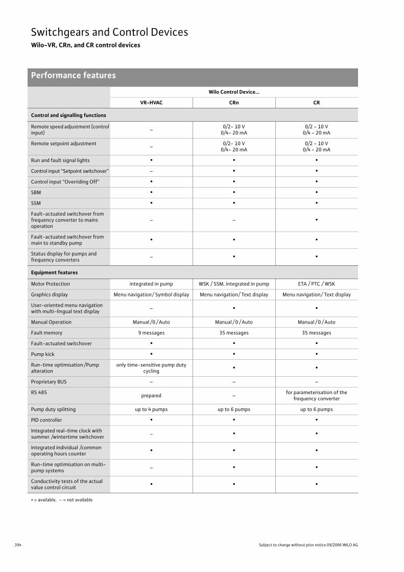
394 Subject to change without prior notice 09/2006 WILO AG
Switchgears and Control DevicesWilo-VR, CRn, and CR control devices
Performance features
Control and signalling functions
Remote speed adjustment (control input)
–0/2- 10 V
0/4- 20 mA0/2 - 10 V
0/4 - 20 mA
Remote setpoint adjustment –
0/2- 10 V0/4- 20 mA
0/2 - 10 V0/4 - 20 mA
Run and fault signal lights • • •
Control input “Setpoint switchover” – • •
Control input “Overriding Off” • • •
SBM • • •
SSM • • •
Fault-actuated switchover from frequency converter to mains operation
– – •
Fault-actuated switchover from main to standby pump
• • •
Status display for pumps and frequency converters
– • •
Equipment features
Motor Protection integrated in pump WSK / SSM, integrated in pump ETA / PTC / WSK
Graphics display Menu navigation/ Symbol display Menu navigation/ Text display Menu navigation/ Text display
User-oriented menu navigation with multi-lingual text display
– • •
Manual Operation Manual /0 / Auto Manual / 0 / Auto Manual / 0 / Auto
Fault memory 9 messages 35 messages 35 messages
Fault-actuated switchover • • •
Pump kick • • •
Run-time optimisation /Pump alteration
only time-sensitive pump duty cycling
• •
Proprietary BUS – – –
RS 485prepared –
for parameterisation of the frequency converter
Pump duty splitting up to 4 pumps up to 6 pumps up to 6 pumps
PID controller • • •
Integrated real-time clock with summer /wintertime switchover
– • •
Integrated individual /common operating hours counter
• • •
Run-time optimisation on multi-pump systems
– • •
Conductivity tests of the actual value control circuit
• • •
Wilo Control Device…
VR-HVAC CRn CR
• = available, – = not available
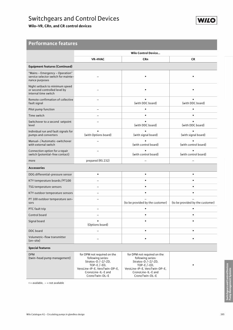
395
Switchgears and Control DevicesWilo-VR, CRn, and CR control devices
Performance features
Wilo Catalogue A1 - Circulating pumps in glandless design
Hea
tin
g, A
ir-c
on
dit
ion
ing
, C
oo
ling
Po
tab
le w
ater
cir
cula
tio
nSo
lar
ther
mal
Serv
ice/
Acc
esso
ries
, Sys
tem
sSw
itch
gear
s an
d C
ontr
ol D
evic
es
Pum
p M
anag
emen
t Sy
stem
s
Equipment features (Continued)
“Mains - Emergency - Operation” service selector switch for mainte-nance purposes
– • •
Night setback to minimum speed or second controlled level by internal time switch
– • •
Remote confirmation of collective fault signal
– •(with DDC board)
• (with DDC board)
Pilot pump function – • •
Time switch – • •
Switchover to a second setpoint level
– •(with DDC board)
•(with DDC board)
Individual run and fault signals for pumps and converters
•(with Options board)
•(with signal board)
•(with signal board)
Manual- / Automatic-switchover with external switch
– •(with control board)
•(with control board)
Connection option for a repair switch (potential-free contact)
– •(with control board)
•(with control board)
more prepared (RS 232) – –
Accessories
DDG differential-pressure sensor • • •
KTY temperature boards / PT100 – • •
TSG temperature sensors – • •
KTY outdoor temperature sensors – • •
PT 100 outdoor temperature sen-sors
– –(to be provided by the customer)
–(to be provided by the customer)
PTC fault trip – • •
Control board – • •
Signal board •(Options board)
• •
DDC board – • •
Volumetric-flow transmitter (on-site)
– • •
Special features
DPM(twin-head pump management)
for DPM not required on the following series:
Stratos-D /-Z/-ZD,TOP-E /-ED,
VeroLine-IP-E, VeroTwin-DP-E, CronoLine-IL-E and
CronoTwin-DL-E
for DPM not required on the following series:
Stratos-D /-Z/-ZD,TOP-E /-ED,
VeroLine-IP-E, VeroTwin-DP-E, CronoLine-IL-E and
CronoTwin-DL-E
•
Wilo Control Device…
VR-HVAC CRn CR
• = available, – = not available
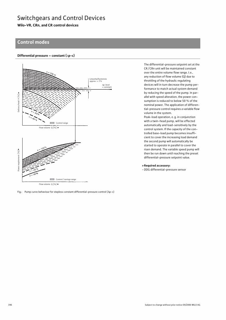
396 Subject to change without prior notice 09/2006 WILO AG
Switchgears and Control DevicesWilo-VR, CRn, and CR control devices
Control modes
Differential pressure – constant ( p-c)
The differential-pressure setpoint set at the
CR / CRn unit will be maintained constant
over the entire volume flow range. I.e.,
any reduction of flow volume (Q) due to
throttling of the hydraulic regulating
devices will in turn decrease the pump per-
formance to match actual system demand
by reducing the speed of the pump. In par-
allel with speed alteration, the power con-
sumption is reduced to below 50 % of the
nominal power. The application of differen-
tial-pressure control requires a variable flow
volume in the system.
Peak-load operation, e. g. in conjunction
with a twin-head pump, will be effected
automatically and load-sensitively by the
control system. If the capacity of the con-
trolled base-load pump becomes insuffi-
cient to cover the increasing load demand
the second pump will automatically be
started to operate in parallel to cover the
risen demand. The variable speed pump will
then be run down until reaching the preset
differential-pressure setpoint value.
> Required accessory:- DDG differential-pressure sensor
Fig.: Pump curve behaviour for stepless constant differential-pressure control ( p-c)
∆p-level = constant
Control range
Flow volume Q [%]
Q [%]
Del
iver
y h
ead
H [
%]
Pow
er re
qu
irem
ent
[%]
Control / savings range
Flow volume
approx. ± 2 % Linearity/hysteresis
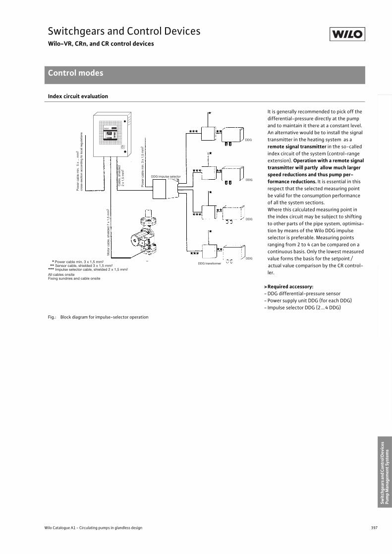
397
Switchgears and Control DevicesWilo-VR, CRn, and CR control devices
Control modes
Wilo Catalogue A1 - Circulating pumps in glandless design
Hea
tin
g, A
ir-c
on
dit
ion
ing
, C
oo
ling
Po
tab
le w
ater
cir
cula
tio
nSo
lar
ther
mal
Serv
ice/
Acc
esso
ries
, Sys
tem
sSw
itch
gear
s an
d C
ontr
ol D
evic
es
Pum
p M
anag
emen
t Sy
stem
s
Index circuit evaluation
It is generally recommended to pick off the
differential-pressure directly at the pump
and to maintain it there at a constant level.
An alternative would be to install the signal
transmitter in the heating system as a
remote signal transmitter in the so-called
index circuit of the system (control-range
extension). Operation with a remote signal transmitter will partly allow much larger speed reductions and thus pump per-formance reductions. It is essential in this
respect that the selected measuring point
be valid for the consumption performance
of all the system sections.
Where this calculated measuring point in
the index circuit may be subject to shifting
to other parts of the pipe system, optimisa-
tion by means of the Wilo DDG impulse
selector is preferable. Measuring points
ranging from 2 to 4 can be compared on a
continuous basis. Only the lowest measured
value forms the basis for the setpoint /
actual value comparison by the CR control-
ler.
>Required accessory:- DDG differential-pressure sensor
- Power supply unit DDG (for each DDG)
- Impulse selector DDG (2...4 DDG)
Fig.: Block diagram for impulse-selector operation
Pow
er c
able
min
. 5
x ...
mm
2
cros
s-se
ctio
n ac
cord
ing
to lo
cal r
egul
atio
ns
Cab
le, s
hiel
ded
2 x
1,5
mm
2
Pow
er c
able
min
. 3 x
1,5
mm
2
DDG impulse selector
Mot
or c
able
, shi
eld
ed 7
x 1
,5 m
m2
DDG transformer
DDG
DDG
DDG
DDG*** Power cable min. 3 x 1,5 mm2
*** Sensor cable, shielded 3 x 1,5 mm2
*** Impulse selector cable, shielded 2 x 1,5 mm2
All cables onsiteFixing sundries and cable onsite
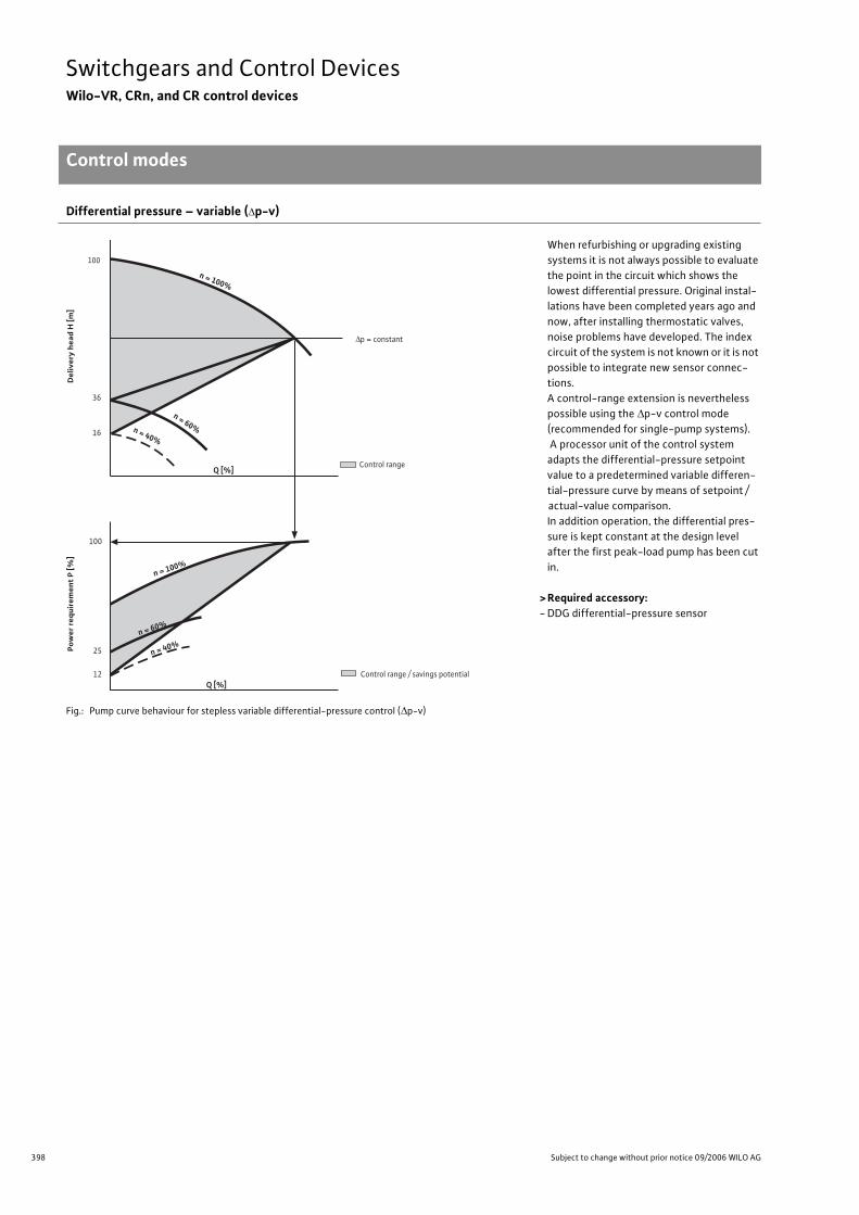
398 Subject to change without prior notice 09/2006 WILO AG
Switchgears and Control DevicesWilo-VR, CRn, and CR control devices
Control modes
Differential pressure – variable ( p-v)
When refurbishing or upgrading existing
systems it is not always possible to evaluate
the point in the circuit which shows the
lowest differential pressure. Original instal-
lations have been completed years ago and
now, after installing thermostatic valves,
noise problems have developed. The index
circuit of the system is not known or it is not
possible to integrate new sensor connec-
tions.
A control-range extension is nevertheless
possible using the p-v control mode
(recommended for single-pump systems).
A processor unit of the control system
adapts the differential-pressure setpoint
value to a predetermined variable differen-
tial-pressure curve by means of setpoint /
actual-value comparison.
In addition operation, the differential pres-
sure is kept constant at the design level
after the first peak-load pump has been cut
in.
> Required accessory:- DDG differential-pressure sensor
Fig.: Pump curve behaviour for stepless variable differential-pressure control ( p-v)
Del
iver
y he
ad H
[m]
Pow
er r
equi
rem
ent
P [%
]
36
16
100
n = 60%
n = 40%
n = 100%
25
12
100
∆p = constant
Control range
Control range / savings potential
n = 100%
n = 40%
Q [%]
Q [%]
n = 60%
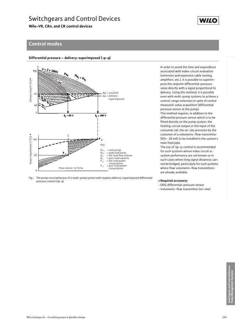
399
Switchgears and Control DevicesWilo-VR, CRn, and CR control devices
Control modes
Wilo Catalogue A1 - Circulating pumps in glandless design
Hea
tin
g, A
ir-c
on
dit
ion
ing
, C
oo
ling
Po
tab
le w
ater
cir
cula
tio
nSo
lar
ther
mal
Serv
ice/
Acc
esso
ries
, Sys
tem
sSw
itch
gear
s an
d C
ontr
ol D
evic
es
Pum
p M
anag
emen
t Sy
stem
s
Differential pressure – delivery-superimposed ( p-q)
In order to avoid the time and expenditure
associated with index-circuit evaluation
(extensive and expensive cable routing,
amplifiers, etc.), it is possible to superim-
pose the setpoint differential-pressure
value directly with a signal proportional to
delivery. Using this method, it is possible
even with multi-pump systems to achieve a
control-range extension in spite of central
measured-value acquisition (differential
pressure sensor at the pump).
This method requires, in addition to the
differential pressure sensor which is to be
fitted directly on the pump system, the
heating-circuit output or the input of the
consumer rail, the on-site provision by the
customer of a volumetric-flow transmitter
(0/4– 20 mA) to be installed in the system's
main feed pipe.
The use of p-q-control is recommended
for such systems whose index circuit or
system performance are not known or in
such cases where long signal distances can-
not be bridged, particularly for such systems
where flow volumetric-flow transmitters
are already available.
>Required accessory:- DDG differential-pressure sensor
- Volumetric-flow transmitter (on-site)
Fig.: The pump curve behaviour of a multi-pump system with stepless delivery-superimposed differential pressure control ( p-q)
Del
iver
y he
adH
[%
] Po
wer
requ
irem
ent
P [
%]
Flow volume Q [%]
Δp = constantΔp = delivery-
superimposed
Key:
Pu H = main pumpPu S = peak load pumpQ V = full-load flow volumeQ T = part-load capacityP 1V = full-load power
consumptionP 1T = part-load power
consumption

400 Subject to change without prior notice 09/2006 WILO AG
Switchgears and Control DevicesWilo-VR, CRn, and CR control devices
Control modes
Differential pressure – temperature-superimposed ( p-T)
The operational performance of the hydrau-
lic system can be further optimised by
adapting the differential-pressure setpoint
value for pump performance control as
a function of a superimposed reference
variable (e.g. outdoor temperature).
The setpoint differential-pressure value and
thus the pump performance is reduced with
rising outside temperatures, it will increase
with falling outside temperatures.
> Required accessory:- DDG differential-pressure sensor
- KTY 10 temperature board
or
- PT 100 temperature board
- Process temperature sensors and outdoor
temperature sensors PT 100 or KTYFig.: Differential-pressure setpoint variation as a function of temperature
Differential temperature control ( T)
Fig.: Flow volume-rate variation as a function of temperature spread
Heating / air-conditioning systems vary in
terms of their cooling / heating require-
ments with expectable outside tempera-
ture fluctuations. A number of installations
are based on constant volume circulation
without fittings to regulate the flow volume
(one-pipe systems, primary circuits, etc.).
Moreover, pure throttling or bypass controls
are highly uneconomical. Added to this
comes the unnecessarily high power con-
sumption (current) to drive the pump during
low load periods.
Differential-temperature control T is one
option of maintaining a constant difference
between feed and return temperatures as a
result of weather- and usage-related tem-
perature spread. The heat flow becomes
variable due to the changes in flow rates
and the transferred heating/cooling capa-
city can be controlled independently of feed
or return temperatures. Differential-tem-
perature control should for reasons of com-
prehensibility only be used with individual
consumers or with systems with a known
control-time constant.
> Required accessory:- KTY 10 temperature board
or
- PT 100 temperature board
- Temperature sensor TSG or PT 100 (on-site)
Temperature T[C]
Dif
fere
ntia
l pre
ssur
e se
tpoi
nt p
[m]
max.
min.
+ 50 - 20
Tem
pera
ture
T[C
]
Q [%]
Feed temperature
Return temperature
25
20
90
70
100
T
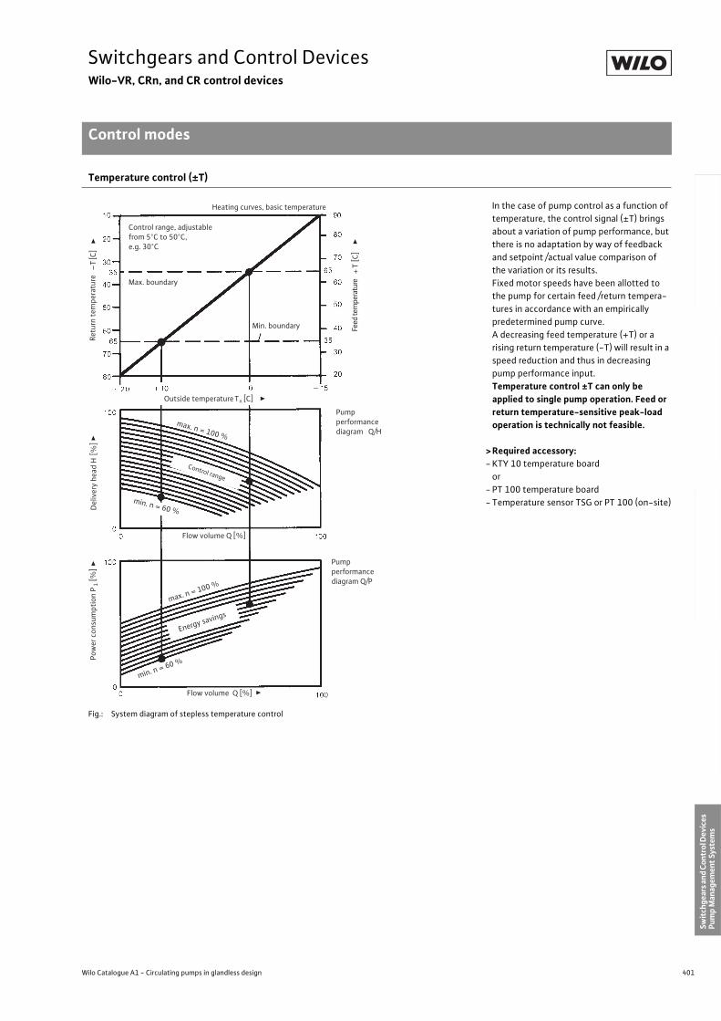
401
Switchgears and Control DevicesWilo-VR, CRn, and CR control devices
Control modes
Wilo Catalogue A1 - Circulating pumps in glandless design
Hea
tin
g, A
ir-c
on
dit
ion
ing
, C
oo
ling
Po
tab
le w
ater
cir
cula
tio
nSo
lar
ther
mal
Serv
ice/
Acc
esso
ries
, Sys
tem
sSw
itch
gear
s an
d C
ontr
ol D
evic
es
Pum
p M
anag
emen
t Sy
stem
s
Temperature control (±T)
In the case of pump control as a function of
temperature, the control signal (±T) brings
about a variation of pump performance, but
there is no adaptation by way of feedback
and setpoint /actual value comparison of
the variation or its results.
Fixed motor speeds have been allotted to
the pump for certain feed /return tempera-
tures in accordance with an empirically
predetermined pump curve.
A decreasing feed temperature (+T) or a
rising return temperature (-T) will result in a
speed reduction and thus in decreasing
pump performance input.
Temperature control ±T can only be applied to single pump operation. Feed or return temperature-sensitive peak-load operation is technically not feasible.
>Required accessory:- KTY 10 temperature board
or
- PT 100 temperature board
- Temperature sensor TSG or PT 100 (on-site)
Fig.: System diagram of stepless temperature control
Heating curves, basic temperature
Min. boundary
Del
iver
y h
ead
Po
wer
co
nsu
mp
tio
nP
1[%
]
Outside temperature
Pump performance diagram Q/H
Pump performance diagram Q/P
Flow volume Q [%]
Ret
urn
tem
per
atu
re –T
[C]
H [
%]
Feed
tem
pera
ture
+T
[C
]
TA [C]
Control range, adjustable from 5°C to 50°C, e.g. 30°C
Max. boundary
Flow volume Q [%]
Control range
max. n = 100 %
min. n = 60 %
max. n = 100 %
min. n = 60 %
Energy savings
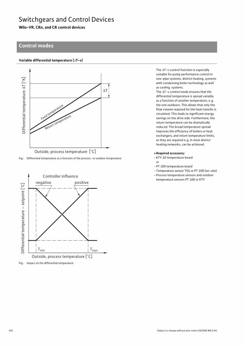
402 Subject to change without prior notice 09/2006 WILO AG
Switchgears and Control DevicesWilo-VR, CRn, and CR control devices
Control modes
Variable differential temperature ( T-v)
The T-v control function is especially
suitable for pump performance control in
one-pipe systems, district heating, systems
with condensing boiler technology as well
as cooling systems.
The T-v control mode ensures that the
differential temperature is spread variably
as a function of another temperature, e.g.
the one outdoors. This allows that only the
flow volume required for the heat transfer is
circulated. This leads to significant energy
savings on the drive side. Furthermore, the
return temperature can be dramatically
reduced. The broad temperature spread
improves the efficiency of boilers or heat
exchangers, and return temperature limits,
as they are required e.g. in most district
heating networks, can be achieved.
> Required accessory:- KTY 10 temperature board
or
- PT 100 temperature board
- Temperature sensor TSG or PT 100 (on-site)
- Process temperature sensors and outdoor
temperature sensors PT 100 or KTY
Fig.: Differential temperature as a function of the process- or outdoor temperature
Fig.: Impact on the differential temperature
Diff
eren
tial
tem
pera
ture
∆T
[°K]
Outside, process temperature [°C]
∆T
Feed temperature
Return temperature
Tmin Tmax
Outside, process temperature [°C]
Controller influence
negative positive
Diff
eren
tial
tem
pera
ture
– s
etpo
int
[°C
]
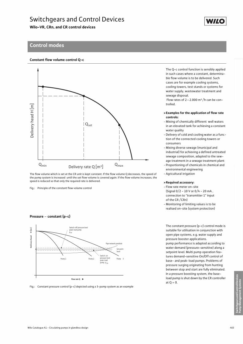
403
Switchgears and Control DevicesWilo-VR, CRn, and CR control devices
Control modes
Wilo Catalogue A1 - Circulating pumps in glandless design
Hea
tin
g, A
ir-c
on
dit
ion
ing
, C
oo
ling
Po
tab
le w
ater
cir
cula
tio
nSo
lar
ther
mal
Serv
ice/
Acc
esso
ries
, Sys
tem
sSw
itch
gear
s an
d C
ontr
ol D
evic
es
Pum
p M
anag
emen
t Sy
stem
s
Constant flow volume control Q-c
The Q-c control function is sensibly applied
in such cases where a constant, determina-
ble flow volume is to be delivered. Such
cases are for example cooling systems,
cooling towers, test stands or systems for
water supply, wastewater treatment and
sewage disposal.
Flow rates of 2–2.000 m³ / h can be con-
trolled.
>Examples for the application of flow rate controls:
- Mixing of chemically different well waters
in an elevated tank for achieving a constant
water quality
- Delivery of cold and cooling water as a func-
tion of the connected cooling towers or
consumers
- Mixing diverse sewage (municipal and
industrial) for achieving a defined untreated
sewage composition, adapted to the sew-
age treatment in a sewage treatment plant
- Proportioning of chemicals in chemical and
environmental engineering
- Agricultural irrigation
>Required accessory:- Flow rate meter on-site
(Signal 0/2 - 10 V or 0/4 - 20 mA ,
connection to “transmitter 1” input
of the CR / CRn)
- Monitoring of limiting values is to be
realised on-site (system protection)
The flow volume which is set at the CR unit is kept constant. If the flow volume Q decreases, the speed of the pump system is increased until the set flow volume is covered again. If the flow volume increases, the speed is reduced so that only the required rate is delivered.
Fig.: Principle of the constant flow volume control
Pressure – constant (p-c)
The constant pressure (p-c) control mode is
suitable for utilisation in conjunction with
open pipe systems, e.g. water supply and
pressure booster applications.
pump performance is adapted according to
water demand (pressure-sensitive) along a
setpoint level. Multi pump operation fea-
tures demand-sensitive On/Off control of
base- and peak-load pumps. Problems of
pressure surging originating from hunting
between stop and start are fully eliminated.
In a pressure boosting system, the base-
load pump is shut down by the CR controller
at Q = 0.Fig.: Constant pressure control (p-c) depicted using a 3-pump system as an example
Qmin Qmax
Del
iver
y he
ad H
[m]
Delivery rate Q [m³]
Qset
De
live
ry h
ead
H [
m] Switch-off pressure level
peak-load pumppOff
Pipe network parabola
Set pointlevel
Pump 3Switch-onpressure levelpeak-load pump p On
Pump 1 Pump 2
Flow rate Q
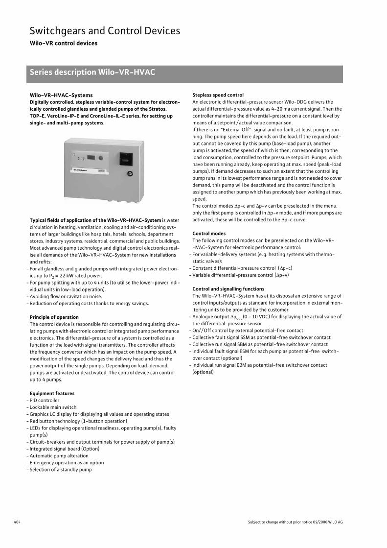
404 Subject to change without prior notice 09/2006 WILO AG
Switchgears and Control DevicesWilo-VR control devices
Series description Wilo-VR-HVAC
Wilo-VR-HVAC-SystemsDigitally controlled, stepless variable-control system for electron-ically controlled glandless and glanded pumps of the Stratos, TOP-E, VeroLine-IP-E and CronoLine-IL-E series, for setting up single- and multi-pump systems.
Typical fields of application of the Wilo-VR-HVAC-System is water
circulation in heating, ventilation, cooling and air-conditioning sys-
tems of larger buildings like hospitals, hotels, schools, department
stores, industry systems, residential, commercial and public buildings.
Most advanced pump technology and digital control electronics real-
ise all demands of the Wilo-VR-HVAC-System for new installations
and refits:
- For all glandless and glanded pumps with integrated power electron-
ics up to P2 = 22 kW rated power.
- For pump splitting with up to 4 units (to utilise the lower-power indi-
vidual units in low-load operation).
- Avoiding flow or cavitation noise.
- Reduction of operating costs thanks to energy savings.
Principle of operationThe control device is responsible for controlling and regulating circu-
lating pumps with electronic control or integrated pump performance
electronics. The differential-pressure of a system is controlled as a
function of the load with signal transmitters. The controller affects
the frequency converter which has an impact on the pump speed. A
modification of the speed changes the delivery head and thus the
power output of the single pumps. Depending on load-demand,
pumps are activated or deactivated. The control device can control
up to 4 pumps.
Equipment features- PID controller
- Lockable main switch
- Graphics LC display for displaying all values and operating states
- Red button technology (1-button operation)
- LEDs for displaying operational readiness, operating pump(s), faulty
pump(s)
- Circuit-breakers and output terminals for power supply of pump(s)
- Integrated signal board (Option)
- Automatic pump alteration
- Emergency operation as an option
- Selection of a standby pump
Stepless speed controlAn electronic differential-pressure sensor Wilo-DDG delivers the
actual differential-pressure value as 4-20 ma current signal. Then the
controller maintains the differential-pressure on a constant level by
means of a setpoint / actual value comparison.
If there is no “External Off”-signal and no fault, at least pump is run-
ning. The pump speed here depends on the load. If the required out-
put cannot be covered by this pump (base-load pump), another
pump is activated,the speed of which is then, corresponding to the
load consumption, controlled to the pressure setpoint. Pumps, which
have been running already, keep operating at max. speed (peak-load
pumps). If demand decreases to such an extent that the controlling
pump runs in its lowest performance range and is not needed to cover
demand, this pump will be deactivated and the control function is
assigned to another pump which has previously been working at max.
speed.
The control modes p-c and p-v can be preselected in the menu,
only the first pump is controlled in p-v mode, and if more pumps are
activated, these will be controlled to the p-c curve.
Control modesThe following control modes can be preselected on the Wilo-VR-
HVAC-System for electronic performance control:
- For variable-delivery systems (e.g. heating systems with thermo-
static valves):
- Constant differential-pressure control ( p-c)
- Variable differential-pressure control ( p-v)
Control and signalling functionsThe Wilo-VR-HVAC-System has at its disposal an extensive range of
control inputs/outputs as standard for incorporation in external mon-
itoring units to be provided by the customer:
- Analogue output pout (0 - 10 VDC) for displaying the actual value of
the differential-pressure sensor
- On/ / Off control by external potential-free contact
- Collective fault signal SSM as potential-free switchover contact
- Collective run signal SBM as potential-free switchover contact
- Individual fault signal ESM for each pump as potential-free switch-
over contact (optional)
- Individual run signal EBM as potential-free switchover contact
(optional)
Series descrip-tion Wilo-VR-HVAC
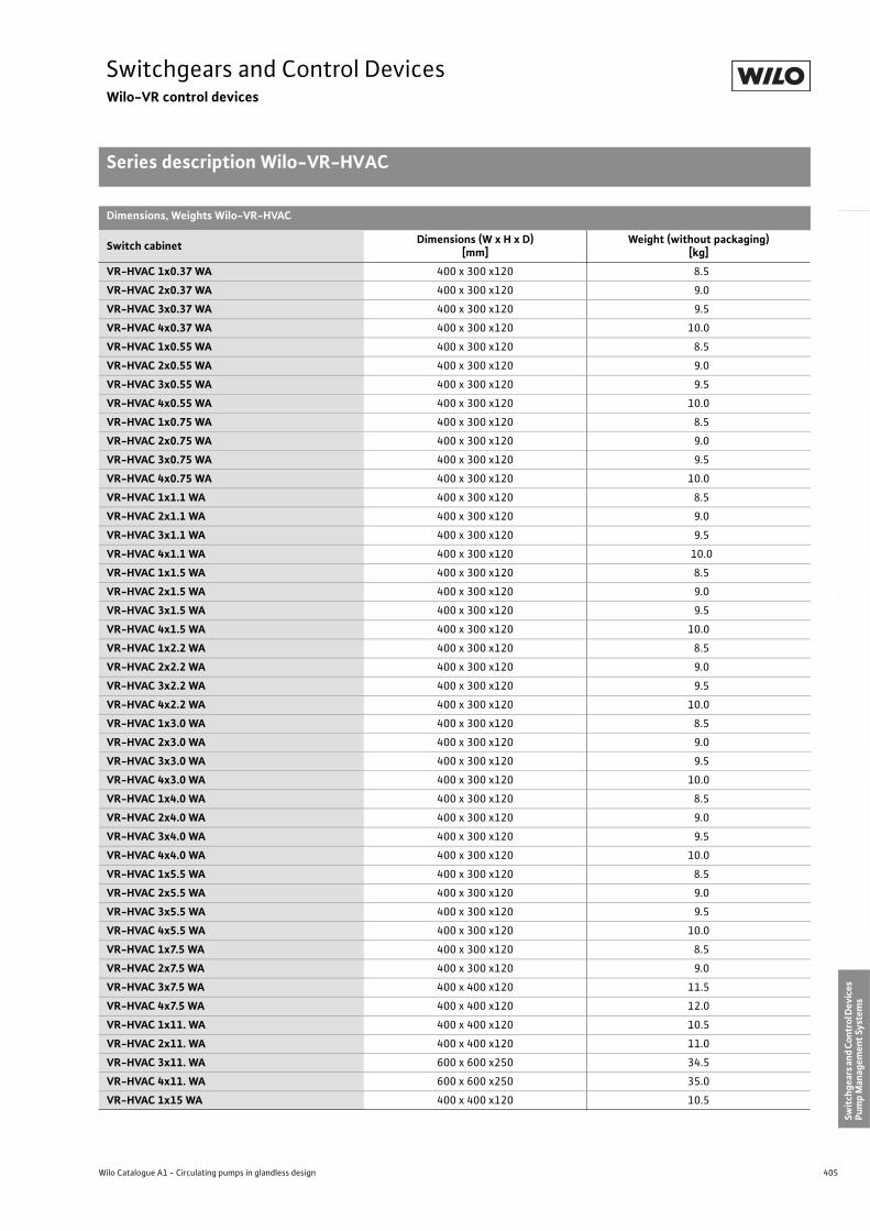
405
Switchgears and Control DevicesWilo-VR control devices
Series description Wilo-VR-HVAC
Wilo Catalogue A1 - Circulating pumps in glandless design
Hea
tin
g, A
ir-c
on
dit
ion
ing
, C
oo
ling
Po
tab
le w
ater
cir
cula
tio
nSo
lar
ther
mal
Serv
ice/
Acc
esso
ries
, Sys
tem
sSw
itch
gear
s an
d C
ontr
ol D
evic
es
Pum
p M
anag
emen
t Sy
stem
s
Dimensions, Weights Wilo-VR-HVAC
Switch cabinetDimensions (W x H x D)
[mm]Weight (without packaging)
[kg]
VR-HVAC 1x0.37 WA 400 x 300 x120 8.5
VR-HVAC 2x0.37 WA 400 x 300 x120 9.0
VR-HVAC 3x0.37 WA 400 x 300 x120 9.5
VR-HVAC 4x0.37 WA 400 x 300 x120 10.0
VR-HVAC 1x0.55 WA 400 x 300 x120 8.5
VR-HVAC 2x0.55 WA 400 x 300 x120 9.0
VR-HVAC 3x0.55 WA 400 x 300 x120 9.5
VR-HVAC 4x0.55 WA 400 x 300 x120 10.0
VR-HVAC 1x0.75 WA 400 x 300 x120 8.5
VR-HVAC 2x0.75 WA 400 x 300 x120 9.0
VR-HVAC 3x0.75 WA 400 x 300 x120 9.5
VR-HVAC 4x0.75 WA 400 x 300 x120 10.0
VR-HVAC 1x1.1 WA 400 x 300 x120 8.5
VR-HVAC 2x1.1 WA 400 x 300 x120 9.0
VR-HVAC 3x1.1 WA 400 x 300 x120 9.5
VR-HVAC 4x1.1 WA 400 x 300 x120 10.0
VR-HVAC 1x1.5 WA 400 x 300 x120 8.5
VR-HVAC 2x1.5 WA 400 x 300 x120 9.0
VR-HVAC 3x1.5 WA 400 x 300 x120 9.5
VR-HVAC 4x1.5 WA 400 x 300 x120 10.0
VR-HVAC 1x2.2 WA 400 x 300 x120 8.5
VR-HVAC 2x2.2 WA 400 x 300 x120 9.0
VR-HVAC 3x2.2 WA 400 x 300 x120 9.5
VR-HVAC 4x2.2 WA 400 x 300 x120 10.0
VR-HVAC 1x3.0 WA 400 x 300 x120 8.5
VR-HVAC 2x3.0 WA 400 x 300 x120 9.0
VR-HVAC 3x3.0 WA 400 x 300 x120 9.5
VR-HVAC 4x3.0 WA 400 x 300 x120 10.0
VR-HVAC 1x4.0 WA 400 x 300 x120 8.5
VR-HVAC 2x4.0 WA 400 x 300 x120 9.0
VR-HVAC 3x4.0 WA 400 x 300 x120 9.5
VR-HVAC 4x4.0 WA 400 x 300 x120 10.0
VR-HVAC 1x5.5 WA 400 x 300 x120 8.5
VR-HVAC 2x5.5 WA 400 x 300 x120 9.0
VR-HVAC 3x5.5 WA 400 x 300 x120 9.5
VR-HVAC 4x5.5 WA 400 x 300 x120 10.0
VR-HVAC 1x7.5 WA 400 x 300 x120 8.5
VR-HVAC 2x7.5 WA 400 x 300 x120 9.0
VR-HVAC 3x7.5 WA 400 x 400 x120 11.5
VR-HVAC 4x7.5 WA 400 x 400 x120 12.0
VR-HVAC 1x11. WA 400 x 400 x120 10.5
VR-HVAC 2x11. WA 400 x 400 x120 11.0
VR-HVAC 3x11. WA 600 x 600 x250 34.5
VR-HVAC 4x11. WA 600 x 600 x250 35.0
VR-HVAC 1x15 WA 400 x 400 x120 10.5
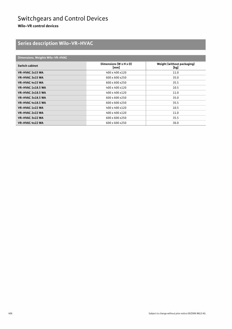
406 Subject to change without prior notice 09/2006 WILO AG
Switchgears and Control DevicesWilo-VR control devices
Series description Wilo-VR-HVAC
VR-HVAC 2x15 WA 400 x 400 x120 11.0
VR-HVAC 3x15 WA 600 x 600 x250 35.0
VR-HVAC 4x15 WA 600 x 600 x250 35.5
VR-HVAC 1x18.5 WA 400 x 400 x120 10.5
VR-HVAC 2x18.5 WA 400 x 400 x120 11.0
VR-HVAC 3x18.5 WA 600 x 600 x250 35.0
VR-HVAC 4x18.5 WA 600 x 600 x250 35.5
VR-HVAC 1x22 WA 400 x 400 x120 10.5
VR-HVAC 2x22 WA 400 x 400 x120 11.0
VR-HVAC 3x22 WA 600 x 600 x250 35.5
VR-HVAC 4x22 WA 600 x 600 x250 36.0
Dimensions, Weights Wilo-VR-HVAC
Switch cabinetDimensions (W x H x D)
[mm]Weight (without packaging)
[kg]
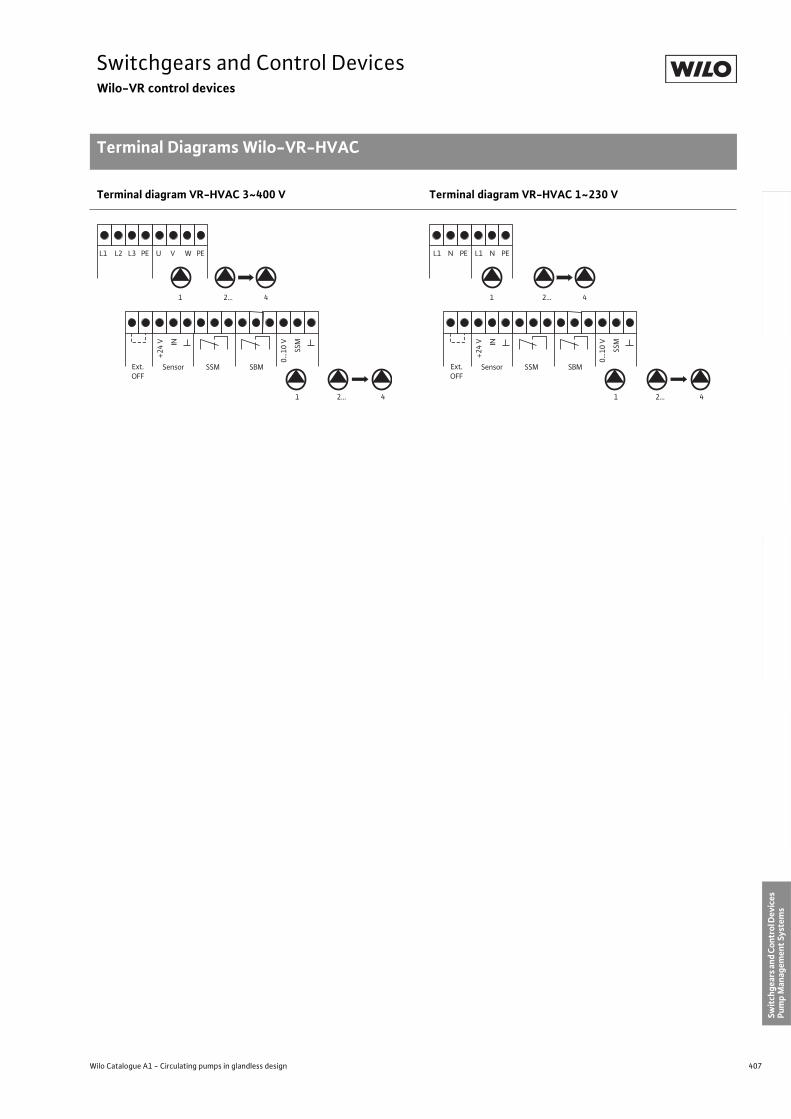
407
Switchgears and Control DevicesWilo-VR control devices
Terminal Diagrams Wilo-VR-HVAC
Wilo Catalogue A1 - Circulating pumps in glandless design
Hea
tin
g, A
ir-c
on
dit
ion
ing
, C
oo
ling
Po
tab
le w
ater
cir
cula
tio
nSo
lar
ther
mal
Serv
ice/
Acc
esso
ries
, Sys
tem
sSw
itch
gear
s an
d C
ontr
ol D
evic
es
Pum
p M
anag
emen
t Sy
stem
s
Terminal diagram VR-HVAC 3~400 V Terminal diagram VR-HVAC 1~230 V
L1 L2 L3 PE
1 42...
1 42...
U V W PE
+24
V
SSM SBMExt.OFF
Sensor
IN
0...1
0 V
SSM
L1 N PE L1 N PE
1 42...
1 42...
+24
V
SSM SBMExt.OFF
Sensor
IN
0...1
0 V
SSM
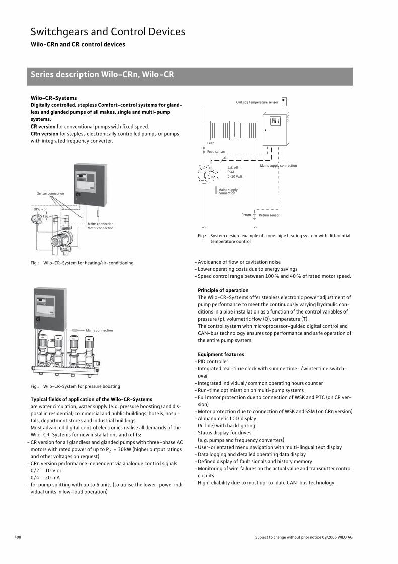
408 Subject to change without prior notice 09/2006 WILO AG
Switchgears and Control DevicesWilo-CRn and CR control devices
Series description Wilo-CRn, Wilo-CR
Wilo-CR-SystemsDigitally controlled, stepless Comfort-control systems for gland-less and glanded pumps of all makes, single and multi-pump systems.CR version for conventional pumps with fixed speed.
CRn version for stepless electronically controlled pumps or pumps
with integrated frequency converter.
Fig.: Wilo-CR-System for heating/air-conditioning
Fig.: Wilo-CR-System for pressure boosting
Typical fields of application of the Wilo-CR-Systemsare water circulation, water supply (e.g. pressure boosting) and dis-
posal in residential, commercial and public buildings, hotels, hospi-
tals, department stores and industrial buildings.
Most advanced digital control electronics realise all demands of the
Wilo-CR-Systems for new installations and refits:
- CR version for all glandless and glanded pumps with three-phase AC
motors with rated power of up to P2 = 30kW (higher output ratings
and other voltages on request)
- CRn version performance-dependent via analogue control signals
0/2 – 10 V or
0/4 – 20 mA
- for pump splitting with up to 6 units (to utilise the lower-power indi-
vidual units in low-load operation)
Fig.: System design, example of a one-pipe heating system with differential temperature control
- Avoidance of flow or cavitation noise
- Lower operating costs due to energy savings
- Speed control range between 100% and 40% of rated motor speed.
Principle of operationThe Wilo-CR-Systems offer stepless electronic power adjustment of
pump performance to meet the continuously varying hydraulic con-
ditions in a pipe installation as a function of the control variables of
pressure (p), volumetric flow (Q), temperature (T).
The control system with microprocessor-guided digital control and
CAN-bus technology ensures top performance and safe operation of
the entire pump system.
Equipment features- PID controller
- Integrated real-time clock with summertime- / wintertime switch-
over
- Integrated individual / common operating hours counter
- Run-time optimisation on multi-pump systems
- Full motor protection due to connection of WSK and PTC (on CR ver-
sion)
- Motor protection due to connection of WSK and SSM (on CRn version)
- Alphanumeric LCD display
(4-line) with backlighting
- Status display for drives
(e.g. pumps and frequency converters)
- User-orientated menu navigation with multi-lingual text display
- Data logging and detailed operating data display
- Defined display of fault signals and history memory
- Monitoring of wire failures on the actual value and transmitter control
circuits
- High reliability due to most up-to-date CAN-bus technology.
Wilo-CRn and CR control devicesSeries descrip-tion Wilo-CRn, Wilo-CR
Sensor connection
DDG - or
TSG
Mains connectionMotor connection
Mains connection
Return Return sensor
Outside temperature sensor
Ext. offSSM0-10 Volt
6
Feed
Feed sensor
Mains supply connection
Mains supplyconnection
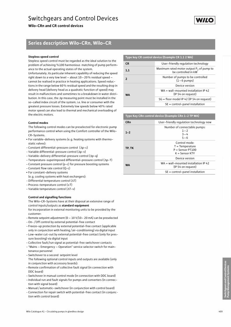
409
Switchgears and Control DevicesWilo-CRn and CR control devices
Series description Wilo-CRn, Wilo-CR
Wilo Catalogue A1 - Circulating pumps in glandless design
Hea
tin
g, A
ir-c
on
dit
ion
ing
, C
oo
ling
Po
tab
le w
ater
cir
cula
tio
nSo
lar
ther
mal
Serv
ice/
Acc
esso
ries
, Sys
tem
sSw
itch
gear
s an
d C
ontr
ol D
evic
es
Pum
p M
anag
emen
t Sy
stem
s
Stepless speed controlStepless speed control must be regarded as the ideal solution to the
problem of achieving %100 harmonious matching of pump perform-
ance to the actual operating states of the system.
Unfortunately, its particular inherent capability of reducing the speed
right down to a very low level – about 10–20% residual speed –
cannot be realised in practice in heating applications. Speed reduc-
tions in the range below 60% residual speed and the resulting drop in
delivery head (delivery head as a quadratic function of speed) may
result in malfunctions and sometimes to a breakdown in water distri-
bution. In this case, the p measuring point must be installed in the
so-called index circuit of the system, i.e. line or consumer with the
greatest pressure losses. Extremely low speeds below 40% rated
motor speed can also lead to thermal and mechanical overloading of
the electric motors.
Control modesThe following control modes can be preselected for electronic pump
performance control when using the Comfort controller of the Wilo-
CR-Systems.
• For variable-delivery systems (e.g. heating systems with thermo-
static valves):
- Constant differential-pressure control ( p-c)
- Variable differential-pressure control ( p-v)
- Variable-delivery differential-pressure control ( p-q)
- Temperature-superimposed differential-pressure control ( p-T)
- Constant pressure control (p-c) for pressure boosting systems
- Constant flow rate control (Q-c)
• For constant-delivery systems
(e.g. cooling systems with heat exchangers):
- Differential temperature control ( T)
- Process-temperature control (±T)
- Variable temperature control ( T-v)
Control and signalling functionsThe Wilo-CR-Systems have at their disposal an extensive range of
control inputs/outputs as standard equipmentfor incorporation in external monitoring units to be provided by the
customer:
- Remote setpoint adjustment (0 – 10 V/10– 20 mA) can be preselected
- On- / Off control by external potential-free contact
- Freeze-up protection by external potential-free contact (applicable
only in conjunction with heating / air-conditioning) via digital input
- Low-water cut-out by external potential-free contact (only for pres-
sure boosting) via digital input
- Collective fault/run signal as potential-free switchover contacts
- “Mains – Emergency – Operation” service selector switch for main-
tenance personnel
- Switchover to a second setpoint level
The following optional control inputs and outputs are available (only
in conjunction with accessory boards):
- Remote confirmation of collective fault signal (in connection with
DDC board)
- Switchover in manual control mode (in connection with DDC board)
- Individual run and fault signals for pumps and converters (in connec-
tion with signal board)
- Manual / automatic-switchover (in conjunction with control board)
- Connection for repair switch with potential-free contact (in conjunc-
tion with control board)
Type key CR control device (Example CR 1.1 2 WA)
CR User-friendly regulation technology
1,1Maximum rated motor output P2 of pump to
be controlled in kW
2Number of pumps to be controlled
(1–6 pumps)
WA
Device version
WA = wall-mounted installation IP 42(IP 54 on request)
SG = floor model IP 42 (IP 54 on request)
SE = control-panel installation
Type Key CRn control device (Example CRn 1-2 TP WA)
CRn User-friendly regulation technology new
1-2
Number of connectable pumps:1–23–45–6
TP, TK
Control mode:T = TemperatureP = Sensor PT100
K = Sensor KTY
WA
Device version
WA = wall-mounted installation IP 42 (IP 54 on request)
SE = control-panel installation
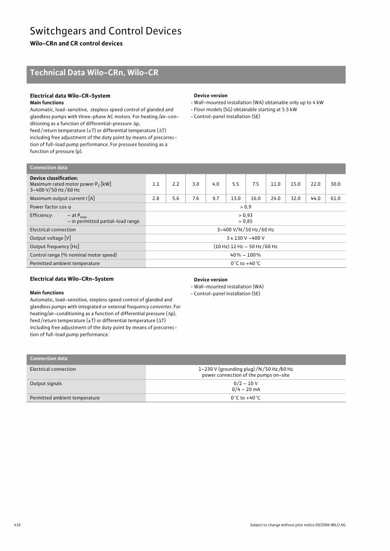
410 Subject to change without prior notice 09/2006 WILO AG
Switchgears and Control DevicesWilo-CRn and CR control devices
Technical Data Wilo-CRn, Wilo-CR
Electrical data Wilo-CR-SystemMain functionsAutomatic, load-sensitive, stepless speed control of glanded and
glandless pumps with three-phase AC motors. For heating /air-con-
ditioning as a function of differential-pressure p,
feed / return temperature (±T) or differential temperature ( T)
including free adjustment of the duty point by means of precorrec-
tion of full-load pump performance. For pressure boosting as a
function of pressure (p).
Device version- Wall-mounted installation (WA) obtainable only up to 4 kW
- Floor models (SG) obtainable starting at 5.5 kW
- Control-panel installation (SE)
Electrical data Wilo-CRn-System
Main functionsAutomatic, load-sensitive, stepless speed control of glanded and
glandless pumps with integrated or external frequency converter. For
heating/air-conditioning as a function of differential pressure ( p),
feed /return temperature (±T) or differential temperature ( T)
including free adjustment of the duty point by means of precorrec-
tion of full-load pump performance.
Device version- Wall-mounted installation (WA)
- Control-panel installation (SE)
Connection data
Device classification:Maximum rated motor power P2 [kW]3~400 V/ 50 Hz / 60 Hz
1.1 2.2 3.0 4.0 5.5 7.5 11.0 15.0 22.0 30.0
Maximum output current I [A] 2.8 5.6 7.6 9.7 13.0 16.0 24.0 32.0 44.0 61.0
Power factor cos > 0,9
Efficiency: – at Pmax– in permitted partial-load range
> 0,93> 0,85
Electrical connection 3~400 V/ N / 50 Hz / 60 Hz
Output voltage [V] 3 x 130 V –400 V
Output frequency [Hz] (10 Hz) 12 Hz – 50 Hz / 60 Hz
Control range (% nominal motor speed) 40% – 100%
Permitted ambient temperature 0°C to +40°C
Connection data
Electrical connection 1~230 V (grounding plug) / N / 50 Hz /60 Hzpower connection of the pumps on-site
Output signals 0/2 – 10 V0/4 – 20 mA
Permitted ambient temperature 0°C to +40°C
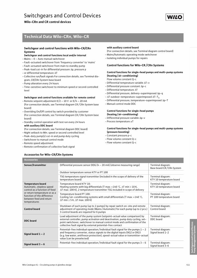
411
Switchgears and Control DevicesWilo-CRn and CR control devices
Technical Data Wilo-CRn, Wilo-CR
Wilo Catalogue A1 - Circulating pumps in glandless design
Hea
tin
g, A
ir-c
on
dit
ion
ing
, C
oo
ling
Po
tab
le w
ater
cir
cula
tio
nSo
lar
ther
mal
Serv
ice/
Acc
esso
ries
, Sys
tem
sSw
itch
gear
s an
d C
ontr
ol D
evic
es
Pum
p M
anag
emen
t Sy
stem
s
Switchgear and control functions with Wilo-CR/CRn SystemsSwitchgear and control functions local and/or internal
- Mains – 0 – Auto manual switchover
- Fault-actuated switchover from ‘frequency converter’ to ‘mains’
- Fault-actuated switchover from main to standby pump
- Peak-load cut-in for differential pressure p, pressure p
- or differential temperature T
- Collective run/fault signals For connection details, see Terminal dia-
gram, CR/CRn System base board
- Pump alteration every 24 hours
- Time-sensitive switchover to minimum speed or second controlled
level
Switchgear and control functions available for remote control- Remote setpoint adjustment 0/2 – 10 V or 0/4 – 20 mA
(For connection details, see Terminal diagram CR / CRn System base
board)
- Overriding On/Off control by switch provided by customer
(For connection details, see Terminal diagram CR / CRn System base
board)
- Standby control operation with test run every 24 hours
with auxiliary DDC board (For connection details, see Terminal diagram DDC board)
- Night setback to Min. speed or second controlled level
- Peak-duty pump(s) cut-in and pump duty cycling
- Switchover to manual control mode
- Remote speed adjustment
- Remote confirmation of collective fault signal
with auxiliary control board (For connection details, see Terminal diagram control board)
- Mains/Automatic operating mode switchover
- Isolating individual pumps for repairs
Control functions for Wilo-CR / CRn Systems
Control functions for single-head pumps and multi-pump systems (heating / air-conditioning)Flow volume constant Q-c
- Differential temperature variable T-v
- Differential pressure constant p-c
- Differential temperature T
- Differential pressure, delivery-superimposed p-q
- T outdoor-temperature-superimposed T-TA
- Differential pressure, temperature-superimposed p-T
- Manual control mode DDC
Control functions for single-head pumps (heating / air-conditioning)
- Differential pressure variable p-v
- Process temperature ±T
Control functions for single-head pumps and multi-pump systems (pressure boosting)
- Constant pressure p-c
- Flow volume constant Q-c
- Flow volume constant Q-c
Accessories for Wilo-CR/CRn Systems
Accessories
Sensor/transmitter Differential pressure sensor DDG (4 – 20 mA) (observe measuring range) Terminal diagram:Base board CR / CRn System
Outdoor temperature sensor KTY or PT 100
TSG temperature signal transmitter (included in the scope of delivery of the temperature board)
Terminal diagram:KTY 10 temperature board
Temperature boardAutomatic, stepless speed control as a function of feed or return temperature or as a function of the difference between feed and return temperatures
Temperature board KTY 10: Heating systems with big differentials (T max: +140 °C, T min 10 K,
T max: 100 K), 2 temperature transmitter TSG included in scope of delivery
Terminal diagram:KTY 10 temperature board
Temperature board PT 100: Cooling / air-conditioning systems with small differentials (T max: +140 °C,
T min 5 K, T max: 100 K)
Terminal diagram:PT 100 temperature board
Control boardShutdown of each pump (up to 2 pumps) by repair switch on-site and remote adjustment of operating mode (Mains / Automatic) for each pump (up to 2 pcs.) 3 control boards are required for 6 pumps
Terminal diagram:Control board
DDC board
Load adjustment of the pump system (setpoint-actual value comparison) by external controller, pump activation and deactivation, pump duty cycling, set-point switchover, switchover to manual control mode and confirmation of the collective fault signal by external potential-free contact
Terminal diagram:DDC board
Signal board 1 – 2
Potential-free individual operation / Individual fault signal for the pumps 1 – 2 and frequency converter, status signals to the digital inputs DIG2 or DIG3 (e.g. low water, antifreeze protection), speed-actual value or transmitter-actual value (can be preselected)
Terminal diagram:Signal board 1-2
Signal board 3 – 6Potential-free individual operation / Individual fault signal for the pumps 3 – 6 Terminal diagram:
Signal board 3-6
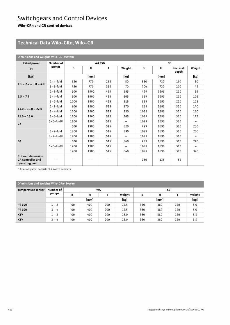
412 Subject to change without prior notice 09/2006 WILO AG
Switchgears and Control DevicesWilo-CRn and CR control devices
Technical Data Wilo-CRn, Wilo-CR
Dimensions and Weights Wilo-CR-System
Rated power Number of pumps
WA / SG SE
p2 B H T Weight B H Rec. inst. depth
Weight
[kW] [mm] [kg] [mm] [kg]
1.1 – 2.2 – 3.0 – 4.01–4-fold 620 770 265 50 550 730 190 30
5–6-fold 780 770 315 70 704 730 200 45
5.5 – 7.5
1–2-fold 600 1900 415 195 499 1696 210 95
3–4-fold 800 1900 415 205 699 1696 210 105
5–6-fold 1000 1900 415 215 899 1696 210 115
11.0 – 15.0 – 22.01–2-fold 800 1900 515 270 699 1696 310 140
3–4-fold 1200 1900 515 350 1099 1696 310 160
11.0 – 15.0 5–6-fold 1200 1900 515 365 1099 1696 310 175
225–6-fold1) 1200 1900 515 – 1099 1696 310 –
600 1900 515 520 499 1696 310 230
30
1–2-fold 1200 1900 515 390 1099 1696 310 200
3–4-fold1) 1200 1900 515 – 1099 1696 310 –
600 1900 515 560 499 1696 310 270
5–6-fold1) 1200 1900 515 – 1099 1696 310 –
1200 1900 515 640 1099 1696 310 320
Cut-out dimensionCR controller and operating unit
– – – – – 186 138 82 –
1) Control system consists of 2 switch cabinets.
Dimensions and Weights Wilo-CRn-System
Temperature sensor Number of pumps
WA SE
B H T Weight B H T Weight
[mm] [kg] [mm] [kg]
PT 100 1 – 2 400 400 200 12.5 360 380 120 5.0
PT 100 3 – 4 400 400 200 12.5 360 380 120 5.0
KTY 1 – 2 400 400 200 13.0 360 380 120 5.5
KTY 3 – 4 400 400 200 13.0 360 380 120 5.5
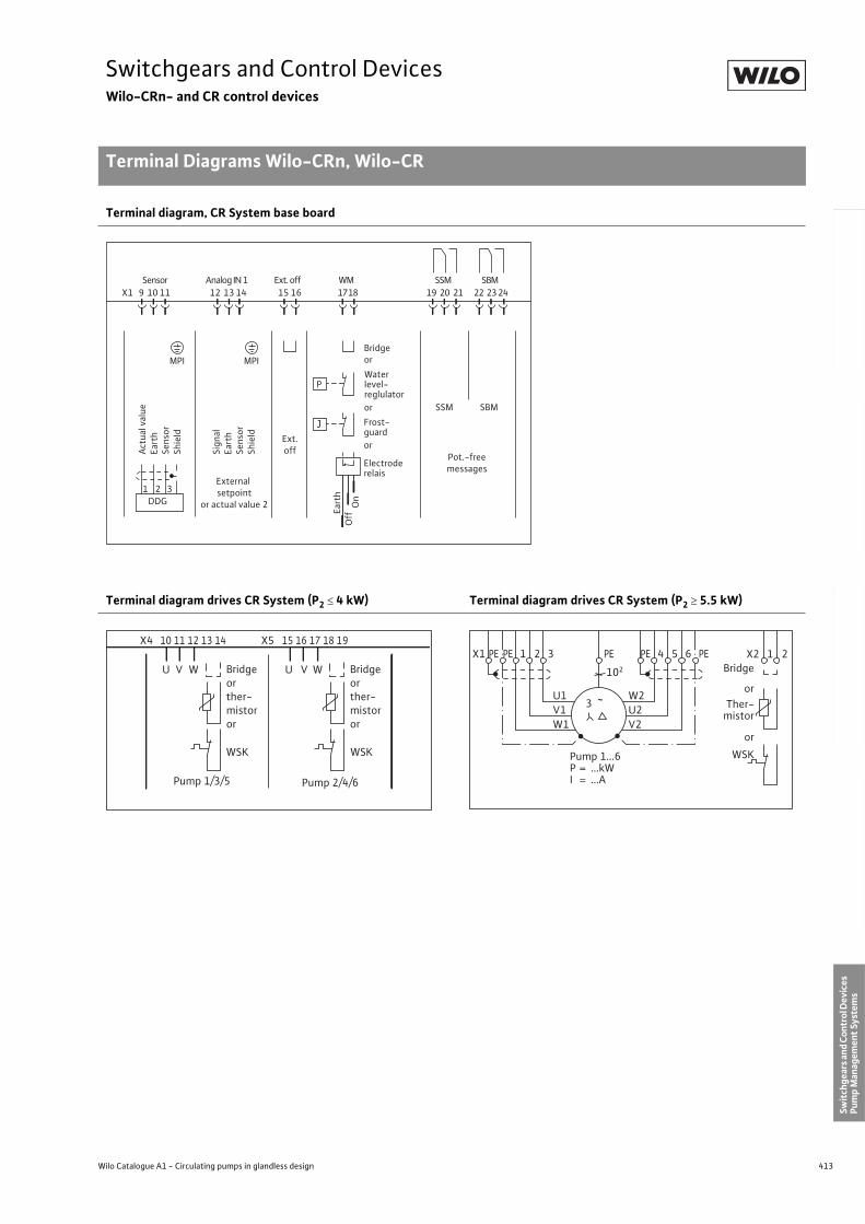
413
Switchgears and Control DevicesWilo-CRn- and CR control devices
Terminal Diagrams Wilo-CRn, Wilo-CR
Wilo Catalogue A1 - Circulating pumps in glandless design
Hea
tin
g, A
ir-c
on
dit
ion
ing
, C
oo
ling
Po
tab
le w
ater
cir
cula
tio
nSo
lar
ther
mal
Serv
ice/
Acc
esso
ries
, Sys
tem
sSw
itch
gear
s an
d C
ontr
ol D
evic
es
Pum
p M
anag
emen
t Sy
stem
s
Terminal diagram, CR System base board
Terminal diagram drives CR System (P2 4 kW) Terminal diagram drives CR System (P2 5.5 kW)
DDG1 2 3
Actu
al v
alue
Eart
hSe
nsor
Shie
ld
Sign
alEa
rth
Sens
orSh
ield
External setpoint
or actual value 2
Ext.off
MPI MPI
SSM SBM
Pot.-freemessages
P
J
Bridgeor
Ea
rth
Off
On
X1 9 10 11 12 13 14 15 16 17 18 19 20 21 22 23 24SSM SBMSensor Analog IN 1 Ext. off WM
Electroderelais
or
Frost-guard
or
Waterlevel-reglulator
X4 10 11 12 13 14 X5 15 16 17 18 19
U V W U V W
WSK WSK
Pump 1/3/5
Bridge or ther- mistor or
Pump 2/4/6
Bridge or ther- mistor or
Bridge
orTher-
mistor
or
WSK
X2 1 2
3 ~
X1 PE PE 1 2 3 PE PE 4 5 6 PE
102
U1V1W1
W2U2V2
Pump 1...6P = ...kWI = ...A
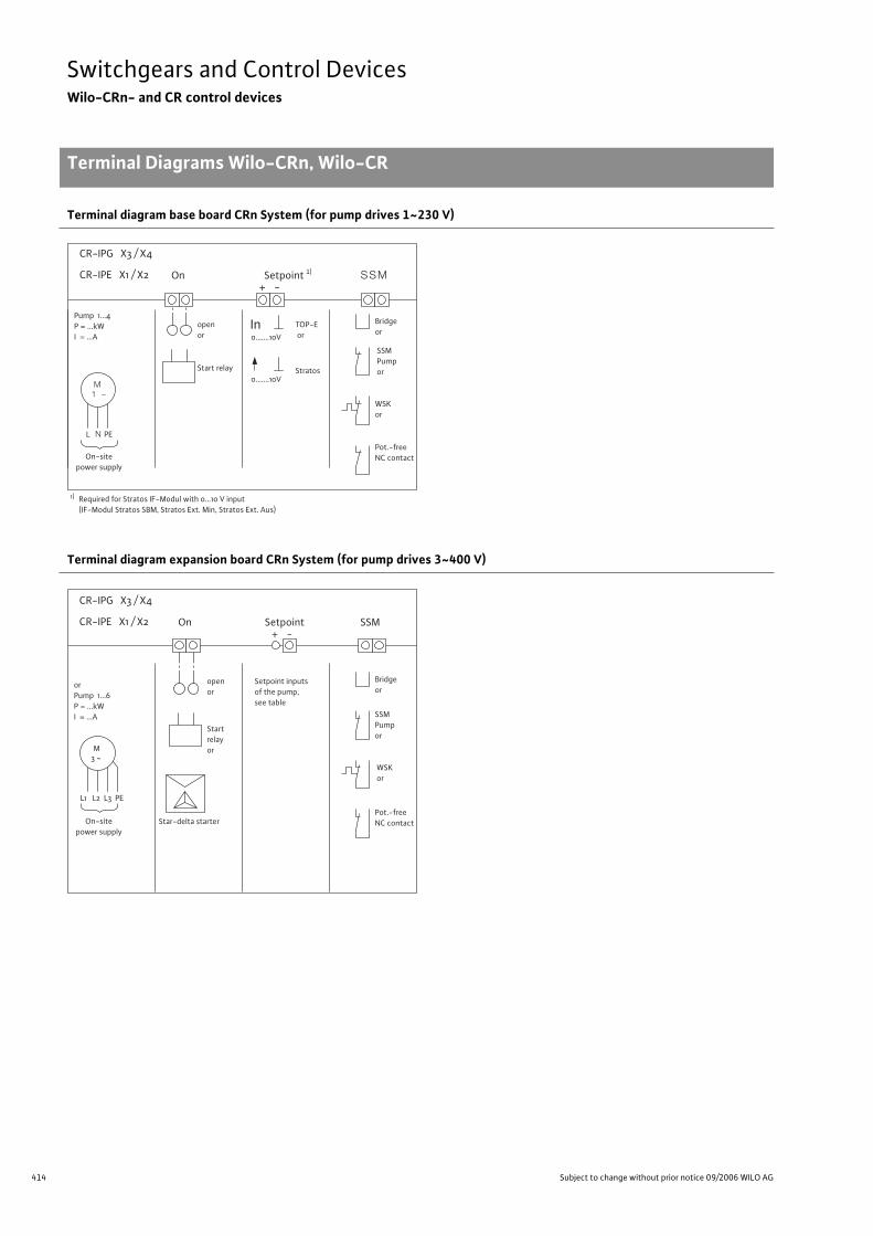
414 Subject to change without prior notice 09/2006 WILO AG
Switchgears and Control DevicesWilo-CRn- and CR control devices
Terminal Diagrams Wilo-CRn, Wilo-CR
Terminal diagram base board CRn System (for pump drives 1~230 V)
Terminal diagram expansion board CRn System (for pump drives 3~400 V)
Bridgeor
SSM
Pump 1...4P = ...kWI = ...A
TOP-E or
openor
WSKor
Pot.-freeNC contact
SSM Pump orStart relay
In0.......10V
Stratos0.......10V
1 ~M
L N PE
1)
On+ -
CR-IPG X3 / X4
CR-IPE X1 / X2
Required for Stratos IF-Modul with 0...10 V input(IF-Modul Stratos SBM, Stratos Ext. Min, Stratos Ext. Aus)
On-sitepower supply
Setpoint 1)
Bridgeor
SSM
orPump 1...6P = ...kWI = ...A
openor
Setpoint inputsof the pump,see table
WSK or
Pot.-freeNC contact
SSMPumpor
Startrelayor
3 ~M
L1 L2 L3 PE
SetpointOn+ -
CR-IPG X3 / X4
CR-IPE X1 / X2
On-sitepower supply
Star-delta starter
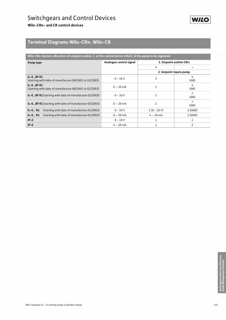
415
Switchgears and Control DevicesWilo-CRn- and CR control devices
Terminal Diagrams Wilo-CRn, Wilo-CR
Wilo Catalogue A1 - Circulating pumps in glandless design
Hea
tin
g, A
ir-c
on
dit
ion
ing
, C
oo
ling
Po
tab
le w
ater
cir
cula
tio
nSo
lar
ther
mal
Serv
ice/
Acc
esso
ries
, Sys
tem
sSw
itch
gear
s an
d C
ontr
ol D
evic
es
Pum
p M
anag
emen
t Sy
stem
s
Wilo-CRn-System, allocation of setpoint outlets: 1. at the control device CRn/2. at the pump to be regulated
Pump type Analogue control signal 1. Setpoint outlets CRn:
+ -
2. Setpoint inputs pump:
IL-E...BF R1(starting with date of manufacture 08/2002 to 02/2003)
0 - 10 V 24
GND
IL-E...BF R1(starting with date of manufacture 08/2002 to 02/2003)
0 – 20 mA 24
GND
IL-E...BF R1 (starting with date of manufacture 03/2003) 0 - 10 V 27
GND
IL-E...BF R1 (starting with date of manufacture 03/2003) 0 – 20 mA 27
GND
IL-E... R1 (starting with date of manufacture 01/2003) 0 - 10 V 1 (0 - 10 V) 2 (GND)
IL-E... R1 (starting with date of manufacture 01/2003) 0 – 20 mA 4 – 20 mA 2 (GND)
IP-E 0 - 10 V 1 2
IP-E 4 – 20 mA 1 2
Terminal Diagrams Wilo-CRn, Wilo-CR
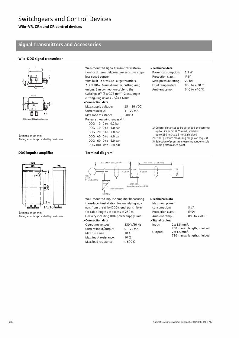
416 Subject to change without prior notice 09/2006 WILO AG
Switchgears and Control DevicesWilo-VR, CRn and CR control devices
Signal Transmitters and Accessories
Wilo-DDG signal transmitter
(Dimensions in mm), Fixing sundries provided by customer
Wall-mounted signal transmitter installa-
tion for differential pressure-sensitive step-
less speed control.
With built-in pressure-surge throttlers,
2 DIN 3862, 6 mm diameter. cutting-ring
unions, 5 m connection cable to the
switchgear1) (3 x 0.75 mm2), 2 pcs. angle
cutting-ring unions R 1/8x ø 6 mm.
> Connection dataMax. supply voltage: 15 – 30 VDC
Current output: 4 – 20 mA
Max. load resistance: 500
Pressure measuring ranges:2) 3)
DDG 2: 0 to 0.2 bar
DDG 10: 0 to 1.0 bar
DDG 20: 0 to 2.0 bar
DDG 40: 0 to 4.0 bar
DDG 60: 0 to 6.0 bar
DDG 100: 0 to 10.0 bar
> Technical data Power consumption: 1.5 W
Protection class: IP 54
Max. pressure rating: 25 bar
Fluid temperature: 0 °C to + 70 °C
Ambient temp.: 0 °C to +40 °C
1) Greater distances to be extended by customer up to 25 m: 3 x 0.75 mm2, shielded up to 250 m: 3 x 1.5 mm2, shielded
2) Other pressure measuring ranges on request3) Selection of pressure measuring range to suit
pump performance point
DDG impulse amplifier Terminal diagram
(Dimensions in mm), Fixing sundries provided by customer
Wall-mounted impulse amplifier (measuring
transducer) installation for amplifying sig-
nals from the Wilo-DDG signal transmitter
for cable lengths in excess of 250 m.
Delivery including DDG power supply unit.
> Connection dataOperating voltage: 230 V/50 Hz
Current input/output: 0 – 20 mA
Max. fuse size: 10 A
Max. input resistance: 50
Max. load resistance: 600
> Technical DataMaximum power
consumption: 5 VA
Protection class: IP 54
Ambient temp.: 0°C to +40°C
> Signal cables:Input: 2 x 1.5 mm2,
250 m max. length, shieldedOutput: 2 x 1.5 mm2,
750 m max. length, shielded
Top view
DDG 10 to 100 (DDG 2 without illustration)
- +24V=
~
CR4-20 mA 4-20 mA
9 10
4 2
7 1
+
-
+
-
1
2
+
+
>
230V 50HzMeasuring transformer DDG
230V 50Hz
Transformer DDG
Wilo-signaltransmitter DDG
123
max. 250 m (2 x 1,5 mm2) max. 750 m (2 x 1,5 mm2)
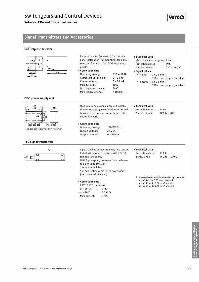
417
Switchgears and Control DevicesWilo-VR, CRn and CR control devices
Signal Transmitters and Accessories
Wilo Catalogue A1 - Circulating pumps in glandless design
Hea
tin
g, A
ir-c
on
dit
ion
ing
, C
oo
ling
Po
tab
le w
ater
cir
cula
tio
nSo
lar
ther
mal
Serv
ice/
Acc
esso
ries
, Sys
tem
sSw
itch
gear
s an
d C
ontr
ol D
evic
es
Pum
p M
anag
emen
t Sy
stem
s
DDG impulse selector
Impulse selector (evaluator) for control-
panel installation (rail mounting) for signal
selection for two to four DDG measuring
points.
>Connection dataOperating voltage: 230 V/ 50 Hz
Current input (2 to 4 x): 0 – 20 mA
Current output: 0 – 20 mA
Max. fuse size: 10 A
Max. input resistance: 50
Max. load resistance: 1000
>Technical DataMax. power consumption: 8 VA
Protection class:I IP 00
Ambient temp.: 0°C to +40°C
>Signal cables:Per input: 2 x 1.5 mm2,
250 m max. length, shielded
Per output: 2 x 1.5 mm2,
750 m max. length, shielded
DDG power supply unit
Fixing sundries provided by customer
Wall-mounted power supply unit installa-
tion for supplying power to the DDG signal
transmitter in conjunction with the DDG
impulse selector.
>Connection dataOperating voltage: 230 V/ 50 Hz
Output voltage: 24 V DC
Output current: 0 – 20 mA
>Technical DataProtection class: IP 54
Ambient temp.: 0°C to +40°C
TSG signal transmitter
Pipe-attached contact temperature sensor.
Included in scope of delivery with KTY 10
temperature board.
With 2 pcs. spring fasteners for attachment
to pipes up to DN 100,
1 tube thermolube,
5 m connection cable to the switchgear1)
(2 x 0.75 mm2, shielded).
>Connection dataKTY 10 PTC thermistor
- at +25°C: 2 k
- at +90°C: 3.09 k
Max. current: 2 mA
>Technical DataProtection class: IP 43
Temp. range: 0°C to + 150°C
1) Greater distances to be extended by customerup to 25 m: 3 x 0.75 mm2, shielded up to 100 m: 3 x 1.50 mm2, shielded up to 250 m: 3 x 2.50 mm2, shielded
70
15
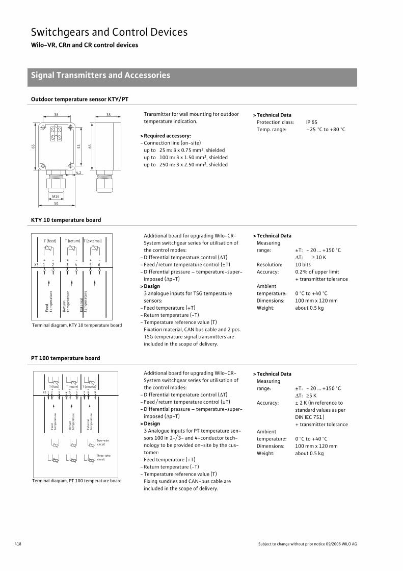
418 Subject to change without prior notice 09/2006 WILO AG
Switchgears and Control DevicesWilo-VR, CRn and CR control devices
Signal Transmitters and Accessories
Outdoor temperature sensor KTY/ PT
Transmitter for wall mounting for outdoor
temperature indication.
> Required accessory:- Connection line (on-site)
up to 25 m: 3 x 0.75 mm2, shielded
up to 100 m: 3 x 1.50 mm2, shielded
up to 250 m: 3 x 2.50 mm2, shielded
> Technical DataProtection class: IP 65
Temp. range: –25 °C to +80 °C
KTY 10 temperature board
Terminal diagram, KTY 10 temperature board
Additional board for upgrading Wilo-CR-
System switchgear series for utilisation of
the control modes:
- Differential temperature control ( T)
- Feed / return temperature control (±T)
- Differential pressure – temperature-super-
imposed ( p-T)
> Design3 analogue inputs for TSG temperature
sensors:
- Feed temperature (+T)
- Return temperature (-T)
- Temperature reference value (T)
Fixation material, CAN bus cable and 2 pcs.
TSG temperature signal transmitters are
included in the scope of delivery.
> Technical DataMeasuring
range: ±T: - 20 ... +150 °C
T: 10 K
Resolution: 10 bits
Accuracy: 0.2% of upper limit
+ transmitter tolerance
Ambient
temperature: 0 °C to +40 °C
Dimensions: 100 mm x 120 mm
Weight: about 0.5 kg
PT 100 temperature board
Terminal diagram, PT 100 temperature board
Additional board for upgrading Wilo-CR-
System switchgear series for utilisation of
the control modes:
- Differential temperature control ( T)
- Feed / return temperature control (±T)
- Differential pressure – temperature-super-
imposed ( p-T)
> Design3 Analogue inputs for PT temperature sen-
sors 100 in 2-/ 3- and 4-conductor tech-
nology to be provided on-site by the cus-
tomer:
- Feed temperature (+T)
- Return temperature (-T)
- Temperature reference value (T)
Fixing sundries and CAN-bus cable are
included in the scope of delivery.
> Technical DataMeasuring
range: ±T: - 20 ... +150 °C
T: 5 K
Accuracy: ± 2 K (in reference to
standard values as per
DIN IEC 751 )
+ transmitter tolerance
Ambient
temperature: 0 °C to +40 °C
Dimensions: 100 mm x 120 mm
Weight: about 0.5 kg
38
4,2
53
65
35
50
M16
65
Feed
tem
pera
ture
Retu
rnte
mpe
ratu
re
Exte
rnal
tem
pera
ture
X3 1 2 3 4 5 6+ - + - + -
T (feed) T (return) T (external)
Feed
te
mpe
ratu
re
Retu
rn
tem
pera
ture
Exte
rnal
tem
pera
ture
X3 1 2 3 4 5 6 7 8 9
T (feed) T (return) T (process) + - + - + -
Two-wire circuit
Three-wire circuit
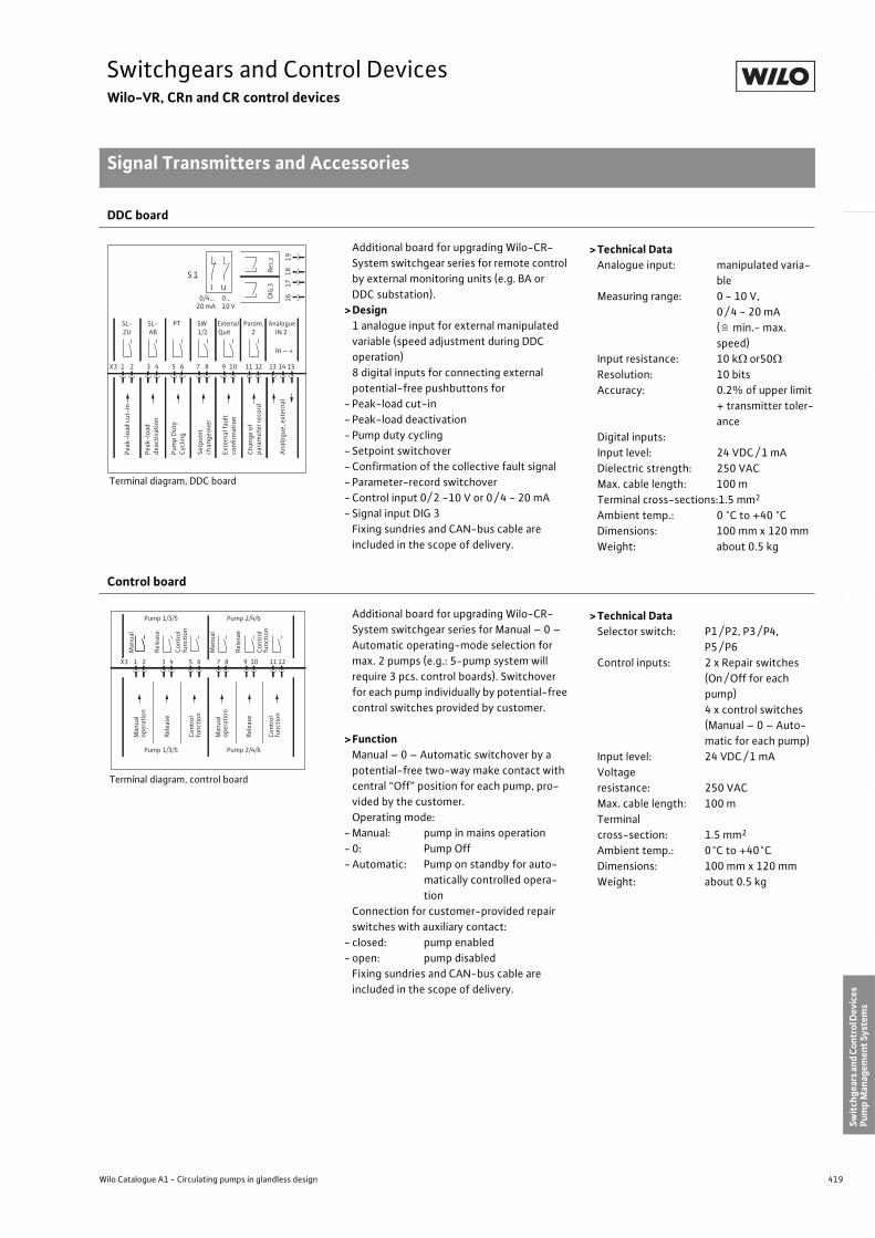
419
Switchgears and Control DevicesWilo-VR, CRn and CR control devices
Signal Transmitters and Accessories
Wilo Catalogue A1 - Circulating pumps in glandless design
Hea
tin
g, A
ir-c
on
dit
ion
ing
, C
oo
ling
Po
tab
le w
ater
cir
cula
tio
nSo
lar
ther
mal
Serv
ice/
Acc
esso
ries
, Sys
tem
sSw
itch
gear
s an
d C
ontr
ol D
evic
es
Pum
p M
anag
emen
t Sy
stem
s
DDC board
Terminal diagram, DDC board
Additional board for upgrading Wilo-CR-
System switchgear series for remote control
by external monitoring units (e.g. BA or
DDC substation).
>Design1 analogue input for external manipulated
variable (speed adjustment during DDC
operation)
8 digital inputs for connecting external
potential-free pushbuttons for
- Peak-load cut-in
- Peak-load deactivation
- Pump duty cycling
- Setpoint switchover
- Confirmation of the collective fault signal
- Parameter-record switchover
- Control input 0/ 2 -10 V or 0 / 4 - 20 mA
- Signal input DIG 3
Fixing sundries and CAN-bus cable are
included in the scope of delivery.
>Technical DataAnalogue input: manipulated varia-
ble
Measuring range: 0 - 10 V,
0 / 4 - 20 mA
( min.- max.
speed)
Input resistance: 10 k or50
Resolution: 10 bits
Accuracy: 0.2% of upper limit
+ transmitter toler-
ance
Digital inputs:
Input level: 24 VDC / 1 mA
Dielectric strength: 250 VAC
Max. cable length: 100 m
Terminal cross-sections:1.5 mm2
Ambient temp.: 0 °C to +40 °C
Dimensions: 100 mm x 120 mm
Weight: about 0.5 kg
Control board
Terminal diagram, control board
Additional board for upgrading Wilo-CR-
System switchgear series for Manual – 0 –
Automatic operating-mode selection for
max. 2 pumps (e.g.: 5-pump system will
require 3 pcs. control boards). Switchover
for each pump individually by potential-free
control switches provided by customer.
>FunctionManual – 0 – Automatic switchover by a
potential-free two-way make contact with
central “Off” position for each pump, pro-
vided by the customer.
Operating mode:
- Manual: pump in mains operation
- 0: Pump Off
- Automatic: Pump on standby for auto-
matically controlled opera-
tion
Connection for customer-provided repair
switches with auxiliary contact:
- closed: pump enabled
- open: pump disabled
Fixing sundries and CAN-bus cable are
included in the scope of delivery.
>Technical DataSelector switch: P1 / P2, P3 / P4,
P5 / P6
Control inputs: 2 x Repair switches
(On / Off for each
pump)
4 x control switches
(Manual – 0 – Auto-
matic for each pump)
Input level: 24 VDC / 1 mA
Voltage
resistance: 250 VAC
Max. cable length: 100 m
Terminal
cross-section: 1.5 mm2
Ambient temp.: 0°C to +40°C
Dimensions: 100 mm x 120 mm
Weight: about 0.5 kg
S1
0/4…
20 mA
0…
10 V
UI
SL- SL- PT SW External Param. Analogue
ZU AB 1/2 Quit 2 IN 2
Pe
ak
-lo
ad
cu
t-in
Pe
ak
-lo
ad
de
ac
tiv
ati
on
Pu
mp
Du
ty
Cy
cli
ng
Se
tpo
int
ch
an
ge
ov
er
Ex
tern
al
fau
lt
co
nfi
rma
tio
n
Ch
an
ge
of
pa
ram
ete
r re
co
rd
An
alo
gu
e,
ex
tern
al
X3 1 2 3 4 5 6 7 8 9 10 11 12 13 14 15
16
17
18
19
In – +
DIG
.3Re
s.2
Pump 1/3/5 Pump 2/4/6
Pump 1/3/5 Pump 2/4/6
Man
ual
op
erat
ion
Rel
ease
Co
ntr
ol
fun
ctio
n
Man
ual
op
erat
ion
Rel
ease
Co
ntr
ol
fun
ctio
n
X3 1 2 3 4 5 6 7 8 9 10 11 12
Man
ual
Rel
ease
Co
ntr
ol
fun
ctio
n
Man
ual
Rel
esae
Co
ntr
ol
fun
ctio
n
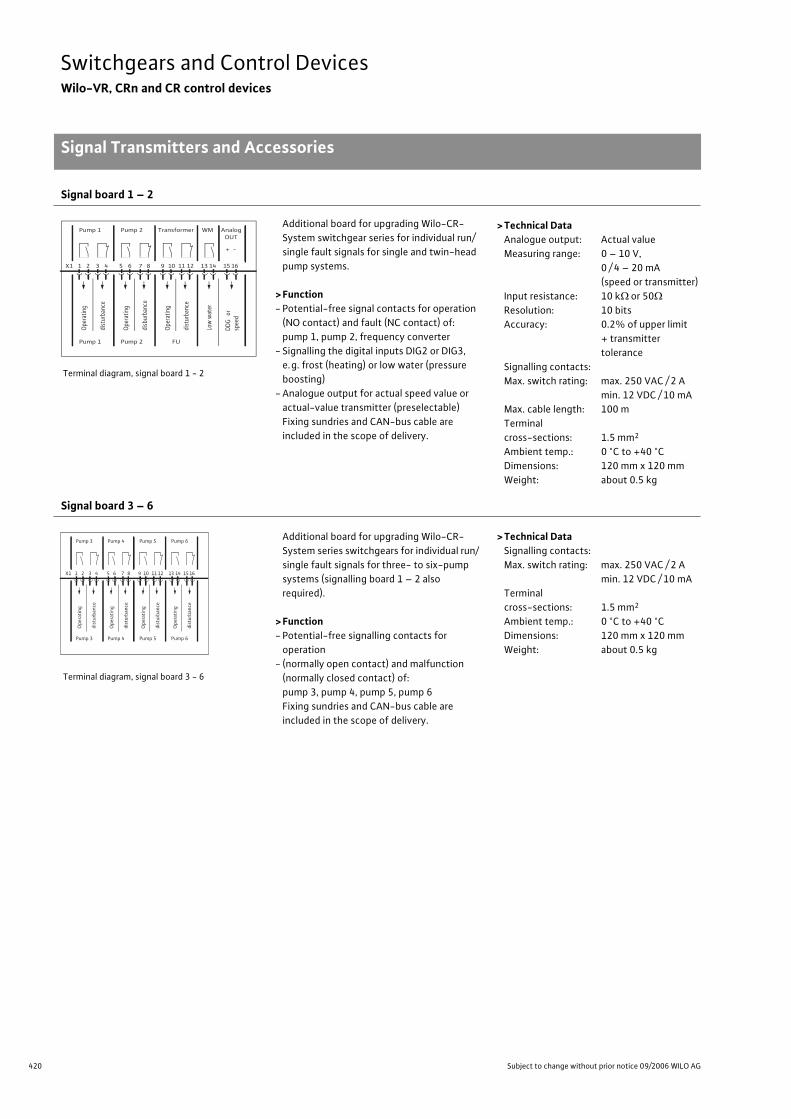
420 Subject to change without prior notice 09/2006 WILO AG
Switchgears and Control DevicesWilo-VR, CRn and CR control devices
Signal Transmitters and Accessories
Signal board 1 – 2
Terminal diagram, signal board 1 - 2
Additional board for upgrading Wilo-CR-
System switchgear series for individual run/
single fault signals for single and twin-head
pump systems.
> Function- Potential-free signal contacts for operation
(NO contact) and fault (NC contact) of:
pump 1, pump 2, frequency converter
- Signalling the digital inputs DIG2 or DIG3,
e.g. frost (heating) or low water (pressure
boosting)
- Analogue output for actual speed value or
actual-value transmitter (preselectable)
Fixing sundries and CAN-bus cable are
included in the scope of delivery.
> Technical DataAnalogue output: Actual value
Measuring range: 0 – 10 V,
0 / 4 – 20 mA
(speed or transmitter)
Input resistance: 10 k or 50
Resolution: 10 bits
Accuracy: 0.2% of upper limit
+ transmitter
tolerance
Signalling contacts:
Max. switch rating: max. 250 VAC / 2 A
min. 12 VDC / 10 mA
Max. cable length: 100 m
Terminal
cross-sections: 1.5 mm2
Ambient temp.: 0 °C to +40 °C
Dimensions: 120 mm x 120 mm
Weight: about 0.5 kg
Signal board 3 – 6
Terminal diagram, signal board 3 - 6
Additional board for upgrading Wilo-CR-
System series switchgears for individual run/
single fault signals for three- to six-pump
systems (signalling board 1 – 2 also
required).
> Function- Potential-free signalling contacts for
operation
- (normally open contact) and malfunction
(normally closed contact) of:
pump 3, pump 4, pump 5, pump 6
Fixing sundries and CAN-bus cable are
included in the scope of delivery.
> Technical DataSignalling contacts:
Max. switch rating: max. 250 VAC / 2 A
min. 12 VDC / 10 mA
Terminal
cross-sections: 1.5 mm2
Ambient temp.: 0 °C to +40 °C
Dimensions: 120 mm x 120 mm
Weight: about 0.5 kg
Pump 1 Pump 2 Transformer WM Analog OUT
Pump 1 Pump 2 FU
Oper
atin
g
dist
urba
nce
X1 1 2 3 4 5 6 7 8 9 10 11 12 13 14 15 16
Oper
atin
g
disb
urba
nce
Oper
atin
g
dist
urba
nce
Low
wat
er
+ -
DDG
or
spee
d
Pump 3 Pump 4 Pump 5 Pump 6
Pump 3 Pump 4 Pump 5 Pump 6
Ope
rati
ng
dist
urba
nce
X1 1 2 3 4 5 6 7 8 9 10 11 12 13 14 15 16
Ope
rati
ng
dist
urba
nce
Ope
rati
ng
dist
urba
nce
Ope
rati
ng
dist
urba
nce
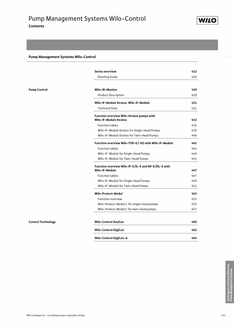
421
Pump Management Systems Wilo-ControlContents
Wilo Catalogue A1 - Circulating pumps in glandless design
Hea
tin
g, A
ir-c
on
dit
ion
ing
, C
oo
ling
Po
tab
le w
ater
cir
cula
tio
nSo
lar
ther
mal
Serv
ice/
Acc
esso
ries
, Sys
tem
sSw
itch
gear
s an
d C
ontr
ol D
evic
es
Pum
p M
anag
emen
t Sy
stem
s
Pump Management Systems Wilo-Control
Series overview 422
Planning Guide 426
Pump Control Wilo-IR-Monitor 429
Product Description 429
Wilo-IF-Moduls Stratos, Wilo-IF-Moduls 431
Technical Data 431
Function overview Wilo-Stratos pumps with Wilo-IF-Moduls Stratos 432
Function tables 432
Wilo-IF-Moduls Stratos for Single-Head Pumps 435
Wilo-IF-Moduls Stratos for Twin-Head Pumps 440
Function overview Wilo-TOP-E/-ED with Wilo-IF-Moduls 445
Function tables 445
Wilo-IF-Moduls for Single-Head Pumps 449
Wilo-IF-Moduls for Twin-Head Pumps 451
Function overview Wilo-IP-E/IL-E and DP-E/DL-E with Wilo-IF-Moduls 447
Function tables 447
Wilo-IF-Moduls for Single-Head Pumps 449
Wilo-IF-Moduls for Twin-Head Pumps 451
Wilo-Protect-Modul 453
Function overview 453
Wilo-Protect-Modul C for single-head pumps 455
Wilo-Protect-Modul C for twin-head pumps 457
Control Technology Wilo-Control AnaCon 460
Wilo-Control DigiCon 462
Wilo-Control DigiCon-A 464
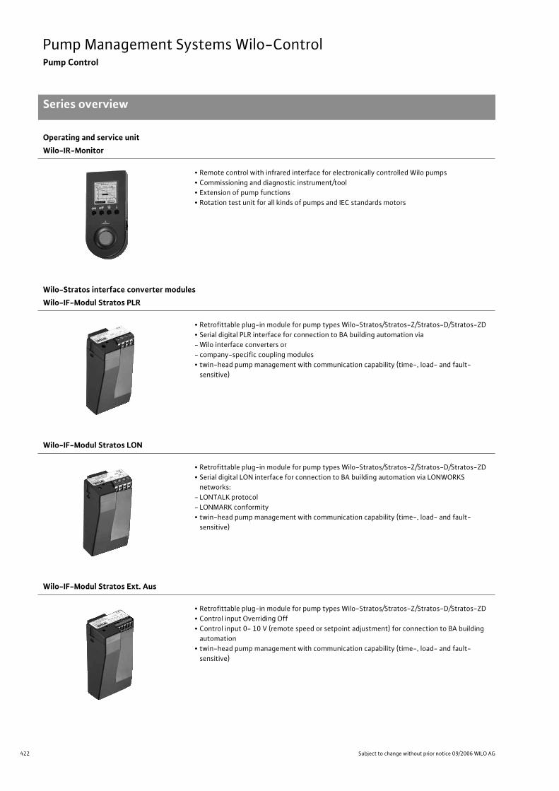
422 Subject to change without prior notice 09/2006 WILO AG
Pump Management Systems Wilo-ControlPump Control
Series overview
Operating and service unit
Wilo-IR-Monitor
• Remote control with infrared interface for electronically controlled Wilo pumps
• Commissioning and diagnostic instrument/tool
• Extension of pump functions
• Rotation test unit for all kinds of pumps and IEC standards motors
Wilo-Stratos interface converter modules
Wilo-IF-Modul Stratos PLR
• Retrofittable plug-in module for pump types Wilo-Stratos/Stratos-Z/Stratos-D/Stratos-ZD
• Serial digital PLR interface for connection to BA building automation via
- Wilo interface converters or
- company-specific coupling modules
• twin-head pump management with communication capability (time-, load- and fault-
sensitive)
Wilo-IF-Modul Stratos LON
• Retrofittable plug-in module for pump types Wilo-Stratos/Stratos-Z/Stratos-D/Stratos-ZD
• Serial digital LON interface for connection to BA building automation via LONWORKS
networks:
- LONTALK protocol
- LONMARK conformity
• twin-head pump management with communication capability (time-, load- and fault-
sensitive)
Wilo-IF-Modul Stratos Ext. Aus
• Retrofittable plug-in module for pump types Wilo-Stratos/Stratos-Z/Stratos-D/Stratos-ZD
• Control input Overriding Off
• Control input 0- 10 V (remote speed or setpoint adjustment) for connection to BA building
automation
• twin-head pump management with communication capability (time-, load- and fault-
sensitive)
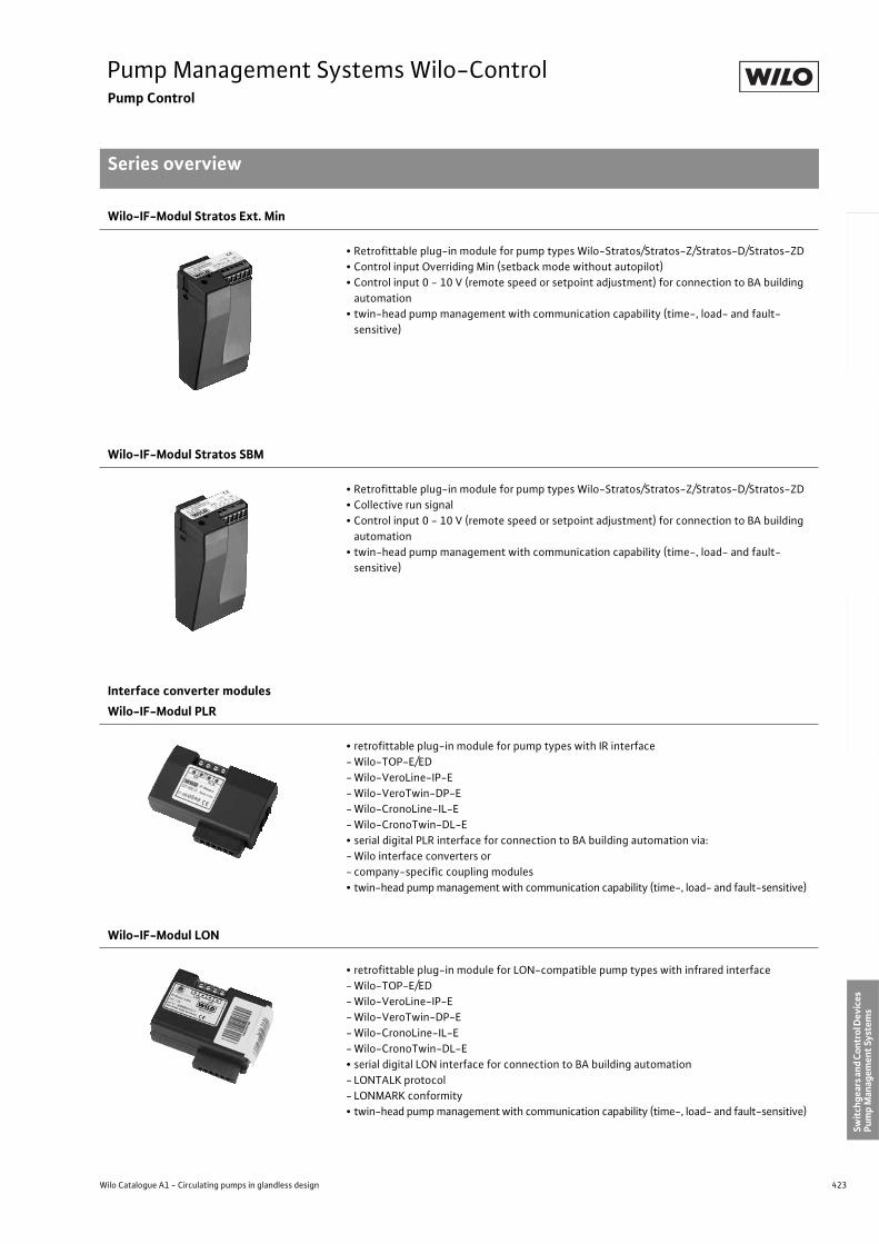
423
Pump Management Systems Wilo-ControlPump Control
Series overview
Wilo Catalogue A1 - Circulating pumps in glandless design
Hea
tin
g, A
ir-c
on
dit
ion
ing
, C
oo
ling
Po
tab
le w
ater
cir
cula
tio
nSo
lar
ther
mal
Serv
ice/
Acc
esso
ries
, Sys
tem
sSw
itch
gear
s an
d C
ontr
ol D
evic
es
Pum
p M
anag
emen
t Sy
stem
s
Wilo-IF-Modul Stratos Ext. Min
• Retrofittable plug-in module for pump types Wilo-Stratos/Stratos-Z/Stratos-D/Stratos-ZD
• Control input Overriding Min (setback mode without autopilot)
• Control input 0 - 10 V (remote speed or setpoint adjustment) for connection to BA building
automation
• twin-head pump management with communication capability (time-, load- and fault-
sensitive)
Wilo-IF-Modul Stratos SBM
• Retrofittable plug-in module for pump types Wilo-Stratos/Stratos-Z/Stratos-D/Stratos-ZD
• Collective run signal
• Control input 0 - 10 V (remote speed or setpoint adjustment) for connection to BA building
automation
• twin-head pump management with communication capability (time-, load- and fault-
sensitive)
Interface converter modules
Wilo-IF-Modul PLR
• retrofittable plug-in module for pump types with IR interface
- Wilo-TOP-E/ED
- Wilo-VeroLine-IP-E
- Wilo-VeroTwin-DP-E
- Wilo-CronoLine-IL-E
- Wilo-CronoTwin-DL-E
• serial digital PLR interface for connection to BA building automation via:
- Wilo interface converters or
- company-specific coupling modules
• twin-head pump management with communication capability (time-, load- and fault-sensitive)
Wilo-IF-Modul LON
• retrofittable plug-in module for LON-compatible pump types with infrared interface
- Wilo-TOP-E/ED
- Wilo-VeroLine-IP-E
- Wilo-VeroTwin-DP-E
- Wilo-CronoLine-IL-E
- Wilo-CronoTwin-DL-E
• serial digital LON interface for connection to BA building automation
- LONTALK protocol
- LONMARK conformity
• twin-head pump management with communication capability (time-, load- and fault-sensitive)
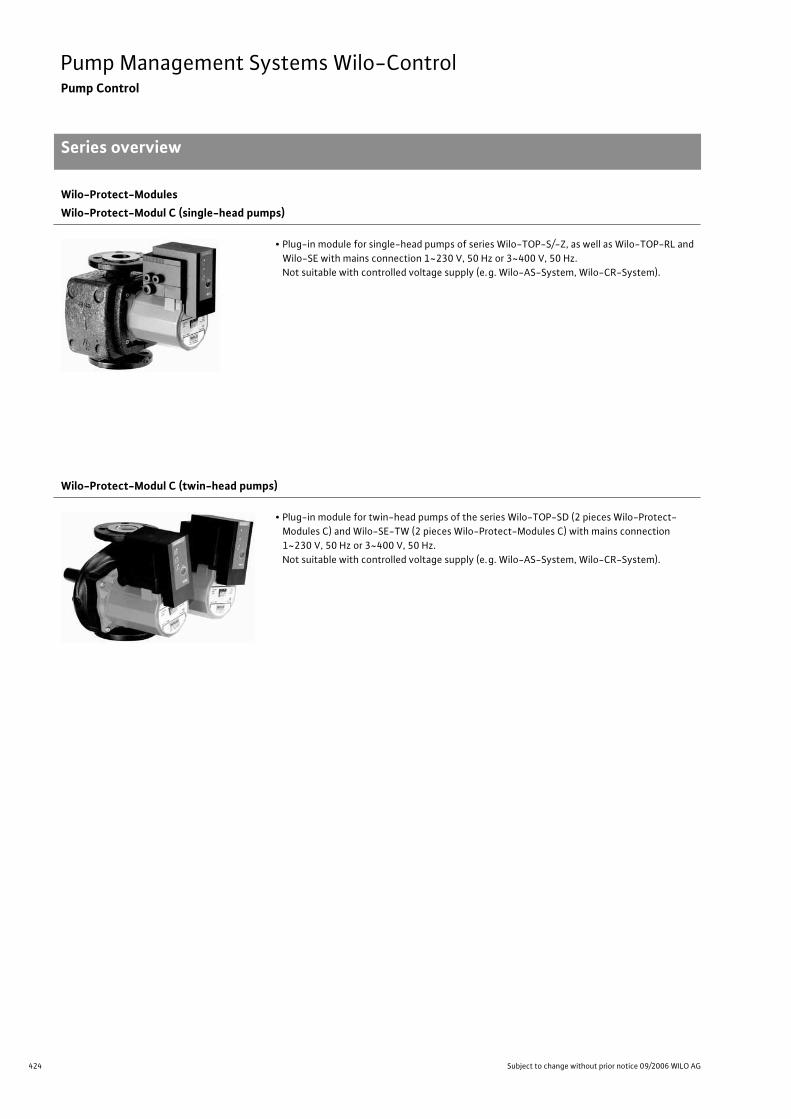
424 Subject to change without prior notice 09/2006 WILO AG
Pump Management Systems Wilo-ControlPump Control
Series overview
Wilo-Protect-Modules
Wilo-Protect-Modul C (single-head pumps)
• Plug-in module for single-head pumps of series Wilo-TOP-S/-Z, as well as Wilo-TOP-RL and
Wilo-SE with mains connection 1~230 V, 50 Hz or 3~400 V, 50 Hz.
Not suitable with controlled voltage supply (e.g. Wilo-AS-System, Wilo-CR-System).
Wilo-Protect-Modul C (twin-head pumps)
• Plug-in module for twin-head pumps of the series Wilo-TOP-SD (2 pieces Wilo-Protect-
Modules C) and Wilo-SE-TW (2 pieces Wilo-Protect-Modules C) with mains connection
1~230 V, 50 Hz or 3~400 V, 50 Hz.
Not suitable with controlled voltage supply (e.g. Wilo-AS-System, Wilo-CR-System).
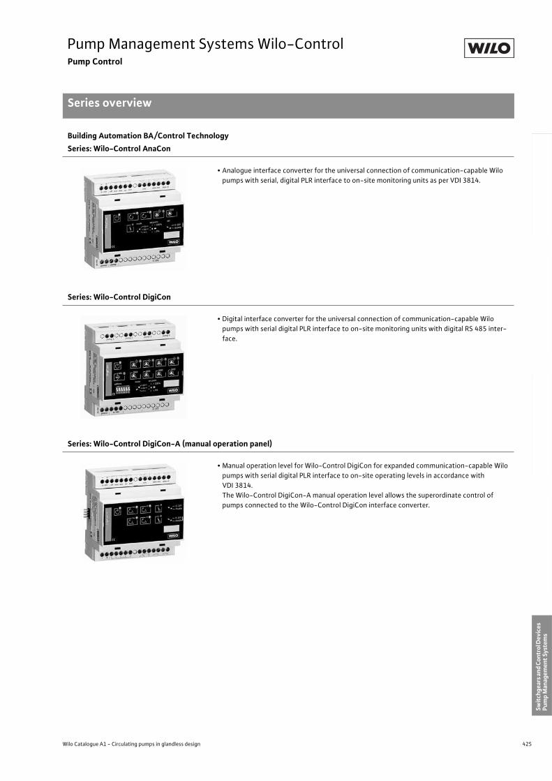
425
Pump Management Systems Wilo-ControlPump Control
Series overview
Wilo Catalogue A1 - Circulating pumps in glandless design
Hea
tin
g, A
ir-c
on
dit
ion
ing
, C
oo
ling
Po
tab
le w
ater
cir
cula
tio
nSo
lar
ther
mal
Serv
ice/
Acc
esso
ries
, Sys
tem
sSw
itch
gear
s an
d C
ontr
ol D
evic
es
Pum
p M
anag
emen
t Sy
stem
s
Building Automation BA/Control Technology
Series: Wilo-Control AnaCon
• Analogue interface converter for the universal connection of communication-capable Wilo
pumps with serial, digital PLR interface to on-site monitoring units as per VDI 3814.
Series: Wilo-Control DigiCon
• Digital interface converter for the universal connection of communication-capable Wilo
pumps with serial digital PLR interface to on-site monitoring units with digital RS 485 inter-
face.
Series: Wilo-Control DigiCon-A (manual operation panel)
• Manual operation level for Wilo-Control DigiCon for expanded communication-capable Wilo
pumps with serial digital PLR interface to on-site operating levels in accordance with
VDI 3814.
The Wilo-Control DigiCon-A manual operation level allows the superordinate control of
pumps connected to the Wilo-Control DigiCon interface converter.
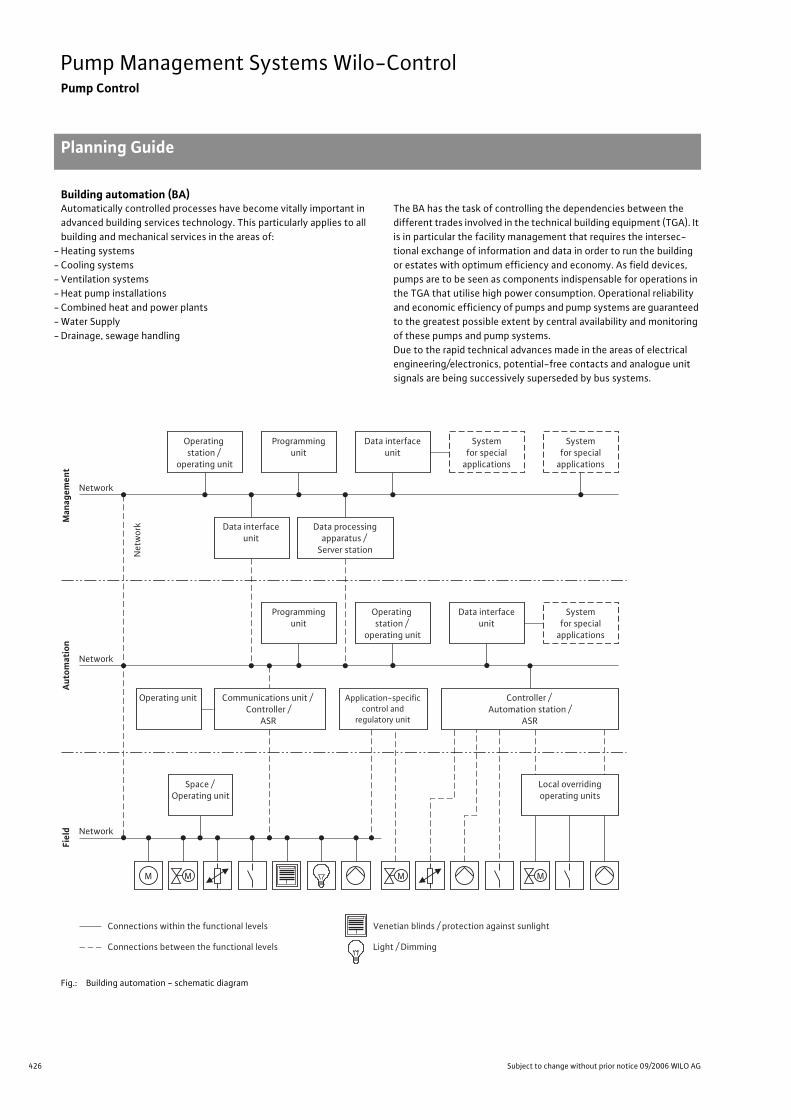
426 Subject to change without prior notice 09/2006 WILO AG
Pump Management Systems Wilo-ControlPump Control
Planning Guide
Building automation (BA)Automatically controlled processes have become vitally important in
advanced building services technology. This particularly applies to all
building and mechanical services in the areas of:
- Heating systems
- Cooling systems
- Ventilation systems
- Heat pump installations
- Combined heat and power plants
- Water Supply
- Drainage, sewage handling
The BA has the task of controlling the dependencies between the
different trades involved in the technical building equipment (TGA). It
is in particular the facility management that requires the intersec-
tional exchange of information and data in order to run the building
or estates with optimum efficiency and economy. As field devices,
pumps are to be seen as components indispensable for operations in
the TGA that utilise high power consumption. Operational reliability
and economic efficiency of pumps and pump systems are guaranteed
to the greatest possible extent by central availability and monitoring
of these pumps and pump systems.
Due to the rapid technical advances made in the areas of electrical
engineering/electronics, potential-free contacts and analogue unit
signals are being successively superseded by bus systems.
Fig.: Building automation - schematic diagram
M M MM
Operating
station /
operating unit
Network
Ne
two
rk
Network
Network
Programming
unit
Data interface
unit
Data processing
apparatus /
Server station
Operating unit Communications unit /
Controller /
ASR
Application-specific
control and
regulatory unit
Controller /
Automation station /
ASR
Data interface
unit
System
for special
applications
System
for special
applications
Programming
unit
Operating
station /
operating unit
Data interface
unit
Space /
Operating unit
Local overriding
operating units
System
for special
applications
Aut
omat
ion
Man
agem
ent
Fiel
d
Venetian blinds / protection against sunlight
Light / Dimming
Connections within the functional levels
Connections between the functional levels
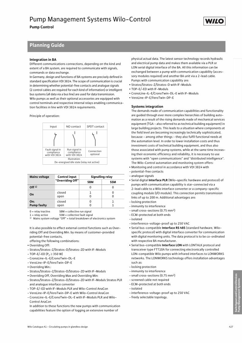
427
Pump Management Systems Wilo-ControlPump Control
Planning Guide
Wilo Catalogue A1 - Circulating pumps in glandless design
Hea
tin
g, A
ir-c
on
dit
ion
ing
, C
oo
ling
Po
tab
le w
ater
cir
cula
tio
nSo
lar
ther
mal
Serv
ice/
Acc
esso
ries
, Sys
tem
sSw
itch
gear
s an
d C
ontr
ol D
evic
es
Pum
p M
anag
emen
t Sy
stem
s
Integration in BADifferent communications connections, depending on the kind and
extent of a BA system, are required to communicate with signals,
commands or data exchange.
In Germany, design and functions of BA systems are precisely defined in
standard specification VDI 3814. The scope of communication is crucial
in determining whether potential-free contacts and analogue signals
(2 control cables are required for each kind of information) or intelligent
bus systems (all data via a bus line) are used for data transmission.
Wilo pumps as well as their optional accessories are equipped with
control terminals and respective internal relays enabling communica-
tion facilities in line with VDI 3814 requirements.
Principle of operation:
It is also possible to effect external control functions such as Over-
riding Off and Overriding Min. by means of customer-provided
potential-free contacts,
offering the following combinations:
• Overriding Off:
- Stratos/Stratos-Z/Stratos-D/Stratos-ZD with IF-Moduls
- TOP-E/-ED (P2 350 W)
- CronoLine-IL-E/CronoTwin-DL-E
- VeroLine-IP-E/VeroTwin-DP-E
• Overriding Min.:
- Stratos/Stratos-Z/Stratos-D/Stratos-ZD with IF-Moduls
• Overriding Off, Overriding Max and Overriding Min:
- Stratos/Stratos-Z/Stratos-D/Stratos-ZD with IF-Moduls Stratos PLR
and analogue interface converter
- TOP-E/-ED with IF-Moduls PLR and Wilo-Control AnaCon
- VeroLine-IP-E/VeroTwin-DP-E with Wilo-Control AnaCon
- CronoLine-IL-E/CronoTwin-DL-E with IF-Moduls PLR and Wilo-
Control AnaCon
In addition to these functions the new pumps with communication
capabilities feature the option of logging an extensive number of
physical actual data. The latest sensor technology records hydraulic
and electrical pump data and makes them available via a PLR or
LON serial digital interface of the BA. All this information can be
exchanged between a pump with communication capability (acces-
sory modules required) and another BA unit via a 2-lead cable.
Pumps with communication capability are:
• Stratos/Stratos-Z/Stratos-D with IF-Moduls
• TOP-E/-ED with IF-Moduls
• CronoLine-IL-E/CronoTwin-DL-E with IF-Moduls
• VeroLine-IP-E/VeroTwin-DP-E
Systems integrationThe demands made of communication capabilities and functionality
are guided through ever more complex hierarchies of building auto-
mation as a result of the rising demands made of mechanical services
equipment (TGA - also referred to as technical building equipment) in
large building projects. This leads to a situation where components at
the field level are becoming increasingly technically sophisticated,
because - among other things - they also fulfil functional needs at
the automation level. In order to lower installation costs and thus
investment costs of technical building equipment, and thus also
those associated with pump systems, while at the same time increas-
ing their economic efficiency and reliability, it is necessary to use
systems with “open communications” and “distributed intelligence”.
The Wilo-Control automation and monitoring system offers:
• Monitoring and control in accordance with VDI 3814 with
- potential-free contacts
- analogue signals
• Serial digital Interface PLR (Wilo-specific hardware and protocol) of
pumps with communication capability is star-connected via a
2-lead cable to a Wilo interface converter or a company-specific
coupling module (I/O module). This connection permits transmission
links of up to 200 m. Additional advantages are:
- locking protection
- immunity to interference
- small cross-sections (0.75 mm2)
- ECM-protected at both ends
- isolated
- interference-voltage-proof up to 250 VAC
• Serial bus-compatible Interface RS 485 (standard hardware, Wilo-
specific protocol) with digital interface converter for communication
with digital monitoring units. The data protocol is to be co-ordinated
with respective BA manufacturer.
• Serial bus-compatible Interface LON with LONTALK protocol and
transceiver type FTT10A for connecting electronically controlled
LON-compatible Wilo pumps with infrared interfaces to LONWORKS
networks. The LONWORKS technology offers installation advantages
such as:
- locking protection
- immunity to interference
- small cross-sections (0.75 mm2)
- screened cable not required
- ECM-protected at both ends
- isolated
- interference-voltage-proof up to 250 VAC
- freely selectable topology.
Mains voltage Control input “Overriding Off”
Signalling relay
SBM SSM
Off 1) 0 0
Onclosedopen
10
00
On;Pump faulty
closedopen
00
11
0 = relay inactive SBM = collective run signal1 = relay active SSM = collective fault signal1) Mains system voltage “Off” = total breakdown of electronics system
Input NO contact SPDT contact
Fault signal in compliance
with VDI 3814
Run signal incompliance
with VDI 3814 Connection
optional
Illustration:De-energised idle state (relay not active)
428 Subject to change without prior notice 09/2006 WILO AG
Pump Management Systems Wilo-ControlPump Control
Planning Guide
LON is an open, non-manufacturer-specific system which enables
open, intersectional communication between different components
and systems. It thus offers advantages to planner, installer and oper-
ator, such as:
• Intersectional trade integration
• Non-manufacturer-specific
• Creation of functional added values
• Avoidance of installation and planning errors thanks to a standard-
ised data interface (prerequisite: no changing transfer media)
• Reduction of installation expenditure in comparison with stand-
alone systems
• Reduced investment costs through multiple utilisation of sensors
• No expensive gateway solutions are required for data communication
between stand-alone systems
• Flexibility in the event of modifications and retrofitting
• Reduced operating costs thanks to intelligent energy management
• Efficiency and operational reliability due to hydraulic load manage-
ment in heating/ventilation/air-conditioning installations
• Overall transparency due to centralised displays, interventions and
monitoring
• Standardised and transparent operation of equipment and building-
services systems
• LONWORKS provides for 2 directions of communication:
• Vertical communication between components on the field level and
automation stations on the automation level
• Horizontal communication between components at the field level
It is horizontal communication in particular which allows the set-up
of decentralised structures which operate without higher-level auto-
mation stations. It has thus become possible to realise previously
expensive control tasks with significantly lower installation expendi-
ture; e.g. a controlled pump with communication capability can
exchange data directly via LON with a valve, a differential-pressure
sensor or a boiler control system and undertake control tasks. In
parallel fashion, the pump can send electrical and hydraulic operating
data for statistical conditioning and if necessary fault and run/
process signals to the higher-level control room and receive higher-
level commands from this control room.
Communication takes place with the standardised LONTALK protocol
and utilises the firmly defined network variables of the LONMARK
“Pump Controller Object for HVAC Applications” functional profiles.
Operating-data management by BAData management by BA systems allows the logging and recording of
cyclical and eventful data, e.g.:
• Maximum output data for p and Q
• Minimum output data for p and Q
• Current power consumption P1
• Operating hours
• Cumulative power consumption
• Status reports
• Fault reports with date, time and cause
The multitude of the information and functions listed allows specific
energy and maintenance management and thus contributes to
reducing costs.
It is thus feasible, by relating the performance and work data to the
measured heating load, to assess overall plant efficiencies and per-
formance data.
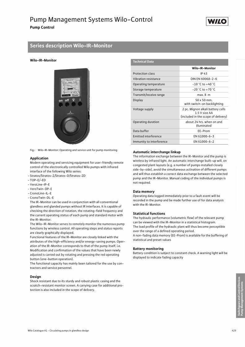
429
Pump Management Systems Wilo-ControlPump Control
Series description Wilo-IR-Monitor
Wilo Catalogue A1 - Circulating pumps in glandless design
Hea
tin
g, A
ir-c
on
dit
ion
ing
, C
oo
ling
Po
tab
le w
ater
cir
cula
tio
nSo
lar
ther
mal
Serv
ice/
Acc
esso
ries
, Sys
tem
sSw
itch
gear
s an
d C
ontr
ol D
evic
es
Pum
p M
anag
emen
t Sy
stem
s
Wilo-IR-Monitor
Fig.: Wilo-IR-Monitor; Operating and service unit for pump monitoring
ApplicationModern operating and servicing equipment for user-friendly remote
control of the electronically controlled Wilo pumps with infrared
interface of the following Wilo series:
- Stratos/Stratos-Z/Stratos-D/Stratos-ZD
- TOP-E/-ED
- VeroLine-IP-E
- VeroTwin-DP-E
- CronoLine-IL-E
- CronoTwin-DL-E
The IR-Monitor can be used in conjunction with all conventional
glandless and glanded pumps without IR interfaces. It is capable of
checking the direction of rotation, the rotating-field frequency and
the current operating status of each pump and standard motor with
the IR-Monitor.
The Wilo-IR-Monitor serves to remotely monitor the numerous pump
functions by wireless control. All operating steps and status reports
are clearly graphically displayed.
Functional features of the IR-Monitor are closely linked with the
attributes of the high-efficiency and/or energy-saving pumps. Oper-
ation of the IR-Monitor corresponds to that of the pump itself, i.e.
Modification and confirmation of the values that have been newly
adjusted is carried out by rotating and pressing the red operating
button (one-button operation).
The functional capacity has mainly been tailored for the use by con-
tractors and service personnel.
DesignShock resistant due to its sturdy and robust plastic casing and the
scratch-resistant monitor screen. A carrying case for additional pro-
tection is also included in the scope of delivery.
Automatic interchange linkupThe information exchange between the IR-Monitor and the pump is
wireless by infrared light. An automatic interchange built-up will, on
congested plant layouts (e.g. a number of pumps installed closely
side-by-side), avoid the simultaneous activation of different pumps
and will thus establish a correct data exchange between the selected
pump and the IR-Monitor. Manual coding of the individual pumps is
not required.
Data memoryOperating data logged immediately prior to a fault event will be
recorded in the pump and be made further use of for data analysis
with the IR-Monitor.
Statistical functionsThe hydraulic performance (volumetric flow) of the relevant pump
can be viewed with the IR-Monitor in a statistical histogram.
The load profile of the hydraulic plant will thus become perceptible
over the range of a defined operating period.
A non-fading data memory (EE-Prom) is available for the buffering of
statistical and preset values
Battery monitoringBattery condition is subject to constant check. A warning light will be
displayed to indicate fading capacity
Technical Data
Wilo-IR-Monitor
Protection class IP 43
Vibration resistance DIN EN 60068-2-6
Operating temperature -10 °C to +40 °C
Storage temperature -20 °C to +70 °C
Transmit/receive range max. 8 m
Display 50 x 50 mm,with switch-on backlighting
Voltage supply 2 pc. Mignon alkali battery cells 1.5 V size AA
(included in the scope of delivery)
Operating duration about 24 hrs. when on and illuminated
Data buffer EE-Prom
Emitted interference EN 61000-6-3
Immunity to interference EN 61000-6-2
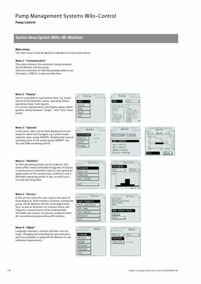
430 Subject to change without prior notice 09/2006 WILO AG
Pump Management Systems Wilo-ControlPump Control
Series description Wilo-IR-Monitor
Main menuThe main menu of the IR-Monitor is divided into 6 function menus:
Menu 1: “Communication”This menu initiates the automatic linkup between the IR-Monitor and the pump.Selective activation of individual pumps within a set of pumps 1000 is also possible here.
Menu 2: “Display”Here it is possible to read system data, e.g. actual electrical and hydraulic values, operating status, operating mode, fault reports.For correct interpretation, the display always distin-guishes clearly between “Single-” and “Twin-head pump”.
Menu 3: “Operate”In this menu, data can be both displayed (current setpoint value) and changed, e.g. control mode, setpoint value, pump ON/OFF, disabling the manual operating level at the pump (pump ON/OFF, Ext. Aus and SSM remaining active).
Menu 4: “Statistics”So that operating periods can be analysed, this menu offers clearly definable histograms of hydrau-lic performance (volumetric flow Q), thus giving an appreciation of the system load conditions over a definable operating period. It also records hours-run and operating data.
Menu 5: “Service”In the service menu the user is given the open of fault diagnosis, fault statistics, function-testing the pump, the IR-Monitor and the serial digital inter-face, as well as direction-of-rotation check and frequency measurement of the rotating field.The latter two checks can also be conducted with all conventional pumps without IR interface.
Menu 6: “Adjust”Language selection, contrast and time-out set-tings, changing and activating the personal pass-word are available to adapt the IR-Monitor to suit individual requirements.
Series descrip-tion Wilo-IR-Monitor
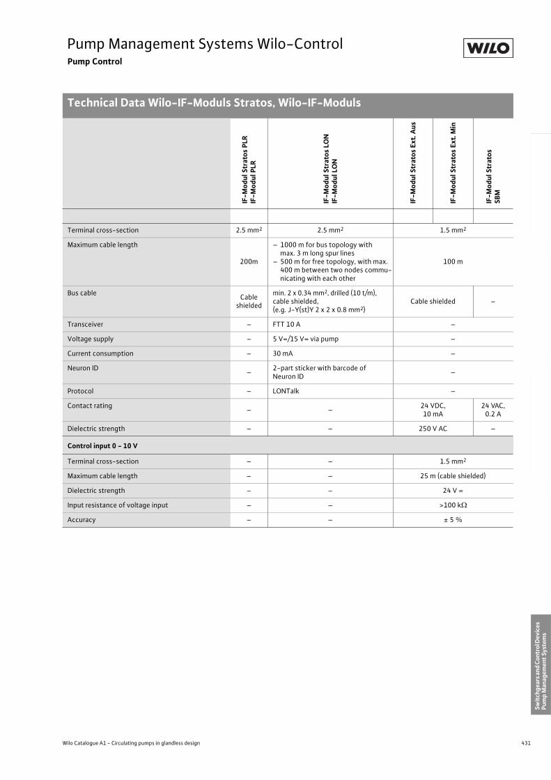
431
Pump Management Systems Wilo-ControlPump Control
Technical Data Wilo-IF-Moduls Stratos, Wilo-IF-Moduls
Wilo Catalogue A1 - Circulating pumps in glandless design
Hea
tin
g, A
ir-c
on
dit
ion
ing
, C
oo
ling
Po
tab
le w
ater
cir
cula
tio
nSo
lar
ther
mal
Serv
ice/
Acc
esso
ries
, Sys
tem
sSw
itch
gear
s an
d C
ontr
ol D
evic
es
Pum
p M
anag
emen
t Sy
stem
s
IF-M
od
ul S
trat
os
PLR
IF-M
od
ul P
LR
IF-M
od
ul S
trat
os
LON
IF-M
od
ul L
ON
IF-M
od
ul S
trat
os
Ext.
Au
s
IF-M
od
ul S
trat
os
Ext.
Min
IF-M
od
ul S
trat
os
SBM
Terminal cross-section 2.5 mm2 2.5 mm2 1.5 mm2
Maximum cable length
200m
– 1000 m for bus topology with max. 3 m long spur lines
– 500 m for free topology, with max. 400 m between two nodes commu-nicating with each other
100 m
Bus cableCable
shielded
min. 2 x 0.34 mm2, drilled (10 t/m),cable shielded,(e.g. J-Y(st)Y 2 x 2 x 0.8 mm2)
Cable shielded –
Transceiver – FTT 10 A –
Voltage supply – 5 V=/15 V= via pump –
Current consumption – 30 mA –
Neuron ID–
2-part sticker with barcode of Neuron ID
–
Protocol – LONTalk –
Contact rating– –
24 VDC, 10 mA
24 VAC,0.2 A
Dielectric strength – – 250 V AC –
Control input 0 - 10 V
Terminal cross-section – – 1.5 mm2
Maximum cable length – – 25 m (cable shielded)
Dielectric strength – – 24 V =
Input resistance of voltage input – – >100 k
Accuracy – – ± 5 %
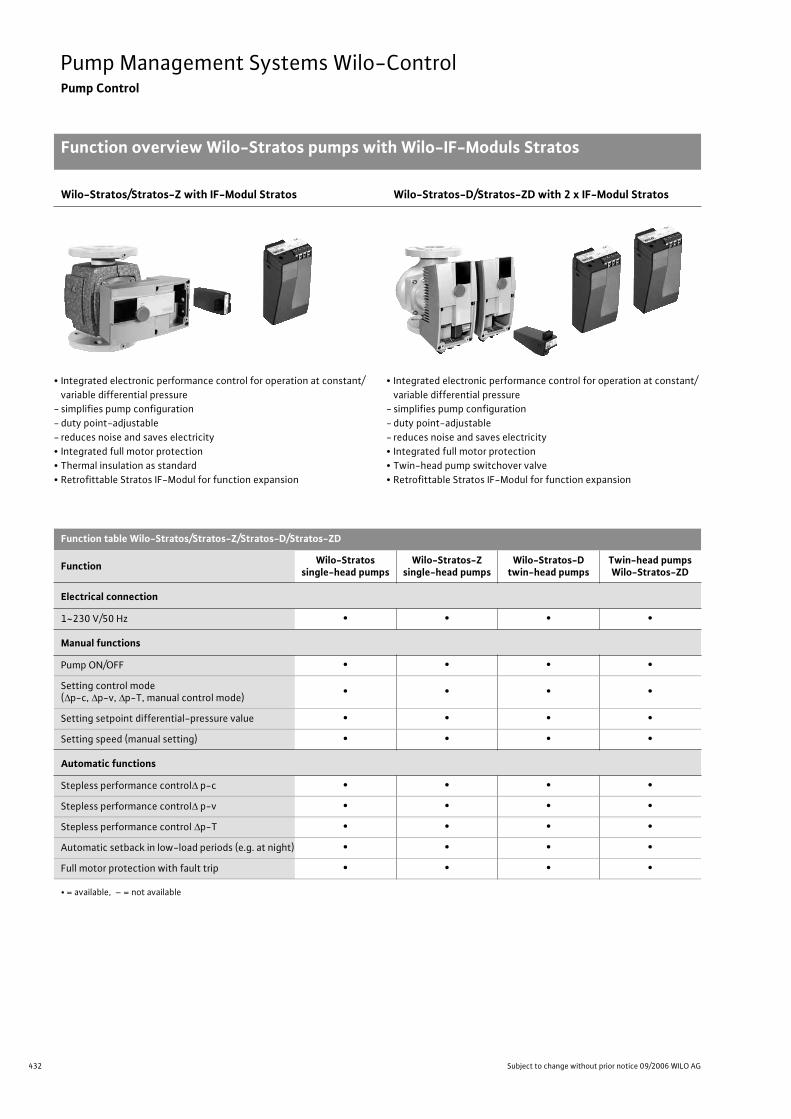
432 Subject to change without prior notice 09/2006 WILO AG
Pump Management Systems Wilo-ControlPump Control
Function overview Wilo-Stratos pumps with Wilo-IF-Moduls Stratos
Wilo-Stratos/Stratos-Z with IF-Modul Stratos Wilo-Stratos-D/Stratos-ZD with 2 x IF-Modul Stratos
• Integrated electronic performance control for operation at constant/
variable differential pressure
- simplifies pump configuration
- duty point-adjustable
- reduces noise and saves electricity
• Integrated full motor protection
• Thermal insulation as standard
• Retrofittable Stratos IF-Modul for function expansion
• Integrated electronic performance control for operation at constant/
variable differential pressure
- simplifies pump configuration
- duty point-adjustable
- reduces noise and saves electricity
• Integrated full motor protection
• Twin-head pump switchover valve
• Retrofittable Stratos IF-Modul for function expansion
Function table Wilo-Stratos/Stratos-Z/Stratos-D/Stratos-ZD
FunctionWilo-Stratos
single-head pumpsWilo-Stratos-Z
single-head pumpsWilo-Stratos-D
twin-head pumpsTwin-head pumpsWilo-Stratos-ZD
Electrical connection
1~230 V/50 Hz • • • •
Manual functions
Pump ON/OFF • • • •
Setting control mode ( p-c, p-v, p-T, manual control mode)
• • • •
Setting setpoint differential-pressure value • • • •
Setting speed (manual setting) • • • •
Automatic functions
Stepless performance control p-c • • • •
Stepless performance control p-v • • • •
Stepless performance control p-T • • • •
Automatic setback in low-load periods (e.g. at night) • • • •
Full motor protection with fault trip • • • •
• = available, – = not available
Function overview Wilo-Stra-tos pumps with Wilo-IF-ModulsStratos
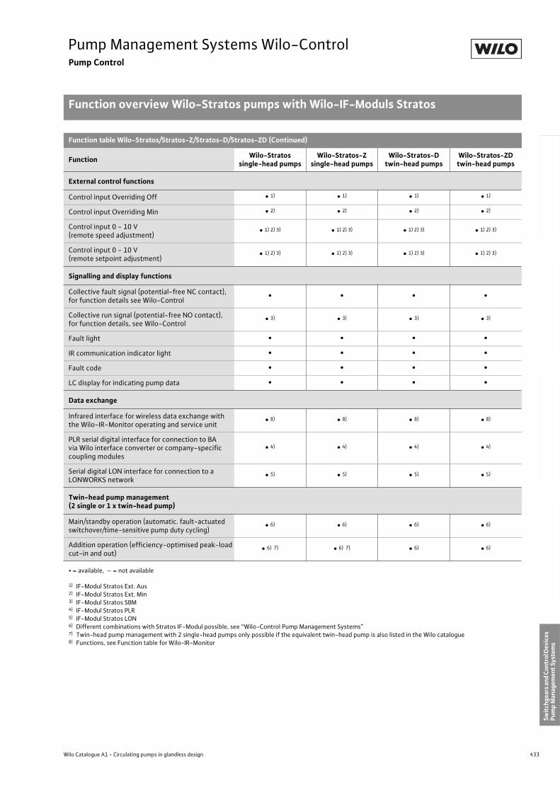
433
Pump Management Systems Wilo-ControlPump Control
Function overview Wilo-Stratos pumps with Wilo-IF-Moduls Stratos
Wilo Catalogue A1 - Circulating pumps in glandless design
Hea
tin
g, A
ir-c
on
dit
ion
ing
, C
oo
ling
Po
tab
le w
ater
cir
cula
tio
nSo
lar
ther
mal
Serv
ice/
Acc
esso
ries
, Sys
tem
sSw
itch
gear
s an
d C
ontr
ol D
evic
es
Pum
p M
anag
emen
t Sy
stem
s
Function table Wilo-Stratos/Stratos-Z/Stratos-D/Stratos-ZD (Continued)
FunctionWilo-Stratos
single-head pumpsWilo-Stratos-Z
single-head pumpsWilo-Stratos-D
twin-head pumpsWilo-Stratos-ZDtwin-head pumps
External control functions
Control input Overriding Off • 1) • 1) • 1) • 1)
Control input Overriding Min • 2) • 2) • 2) • 2)
Control input 0 - 10 V (remote speed adjustment)
• 1) 2) 3) • 1) 2) 3) • 1) 2) 3) • 1) 2) 3)
Control input 0 - 10 V(remote setpoint adjustment)
• 1) 2) 3) • 1) 2) 3) • 1) 2) 3) • 1) 2) 3)
Signalling and display functions
Collective fault signal (potential-free NC contact), for function details see Wilo-Control
• • • •
Collective run signal (potential-free NO contact), for function details, see Wilo-Control
• 3) • 3) • 3) • 3)
Fault light • • • •
IR communication indicator light • • • •
Fault code • • • •
LC display for indicating pump data • • • •
Data exchange
Infrared interface for wireless data exchange with the Wilo-IR-Monitor operating and service unit
• 8) • 8) • 8) • 8)
PLR serial digital interface for connection to BA via Wilo interface converter or company-specific coupling modules
• 4) • 4) • 4) • 4)
Serial digital LON interface for connection to a LONWORKS network
• 5) • 5) • 5) • 5)
Twin-head pump management(2 single or 1 x twin-head pump)
Main/standby operation (automatic. fault-actuated switchover/time-sensitive pump duty cycling)
• 6) • 6) • 6) • 6)
Addition operation (efficiency-optimised peak-load cut-in and out)
• 6) 7) • 6) 7) • 6) • 6)
• = available, – = not available
1) IF-Modul Stratos Ext. Aus2) IF-Modul Stratos Ext. Min3) IF-Modul Stratos SBM4) IF-Modul Stratos PLR5) IF-Modul Stratos LON6) Different combinations with Stratos IF-Modul possible, see “Wilo-Control Pump Management Systems”7) Twin-head pump management with 2 single-head pumps only possible if the equivalent twin-head pump is also listed in the Wilo catalogue8) Functions, see Function table for Wilo-IR-Monitor
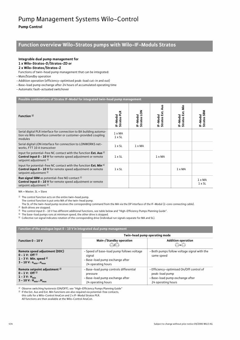
434 Subject to change without prior notice 09/2006 WILO AG
Pump Management Systems Wilo-ControlPump Control
Function overview Wilo-Stratos pumps with Wilo-IF-Moduls Stratos
Integrable dual pump management for 1 x Wilo-Stratos-D/Stratos-ZD or 2 x Wilo-Stratos/Stratos-ZFunctions of twin-head pump management that can be integrated:
- Main/Standby operation
- Addition operation (efficiency-optimised peak-load cut-in and out)
- Base-load pump exchange after 24 hours of accumulated operating time
- Automatic fault-actuated switchover
Possible combinations of Stratos IF-Modul for integrated twin-head pump management
Function 1)IF
-Mo
du
l St
rato
s P
LR
IF-M
od
ul
Stra
tos
LON
IF-M
od
ul
Stra
tos
Ext.
Au
s
IF-M
od
ul
Stra
tos
Ext.
Min
IF-M
od
ul
Stra
tos
SBM
Serial digital PLR interface for connection to BA building automa-tion via Wilo interface converter or customer-provided coupling modules
1 x MA1 x SL
Serial digital LON interface for connection to LONWORKS net-works, FTT 10 A transceiver
1 x SL 1 x MA
Input for potential-free NC contact with the function Ext. Aus 2)
Control input 0 - 10 V for remote speed adjustment or remote setpoint adjustment 3)
1 x SL 1 x MA
Input for potential-free NC contact with the function Ext. Min 4)
Control input 0 - 10 V for remote speed adjustment or remote setpoint adjustment 3)
1 x SL 1 x MA
Run signal SBM as potential-free NO contact 5)
Control input 0 - 10 V for remote speed adjustment or remote setpoint adjustment 3)
1 x MA1 x SL
MA = Master, SL = Slave
1) The control function acts on the entire twin-head pump.The control function is put onto MA of the twin-head pump.The SL of the twin-head pump receives the corresponding command from the MA via the DP interface of the IF-Modul (2-core connecting cable).
2) Both drives are stopped.3) The control input 0 - 10 V has different additional functions, see table below and “High-Efficiency Pumps Planning Guide”.4) The base-load pumps runs at minimum speed, the other drive is stopped.5) Collective run signal indicates rotation of the corresponding drive (individual run signals separate for MA and SL).
Function of the analogue input 0 - 10 V in integrated dual pump management
Function 0 - 10 V
Twin-head pump operating mode
Main-/ Standby operation
/
Addition operation
+
Remote speed adjustment (DDC)0 - 1 V: Off 1)
1 - 3 V: Min. speed 1)
3 - 10 V: nmin…nmax
- Speed of base-load pump follows voltage
signal
- Base-load pump exchange after
24 operating hours
- Both pumps follow voltage signal with the
same speed
Remote setpoint adjustment 2)
0 - 1 V: Off 1)
1 - 3 V: Hmin3 - 10 V: Hmin…Hmax
- Base-load pump controls differential
pressure
- Base-load pump exchange after
24 operating hours
- Efficiency-optimised On/Off control of
peak-load pump
- Base-load pump exchange after
24 operating hours
1) Observe switching hysteresis (ON/OFF), see “High-Efficiency Pumps Planning Guide”2) If the Ext. Aus and Ext. Min functions are also required via potential-free contacts,
this calls for a Wilo-Control AnaCon and 2 x IF-Modul Stratos PLR.All functions are then available at the Wilo-Control AnaCon.
Function overview Wilo-Stra-tos pumps with Wilo-IF-ModulsStratos
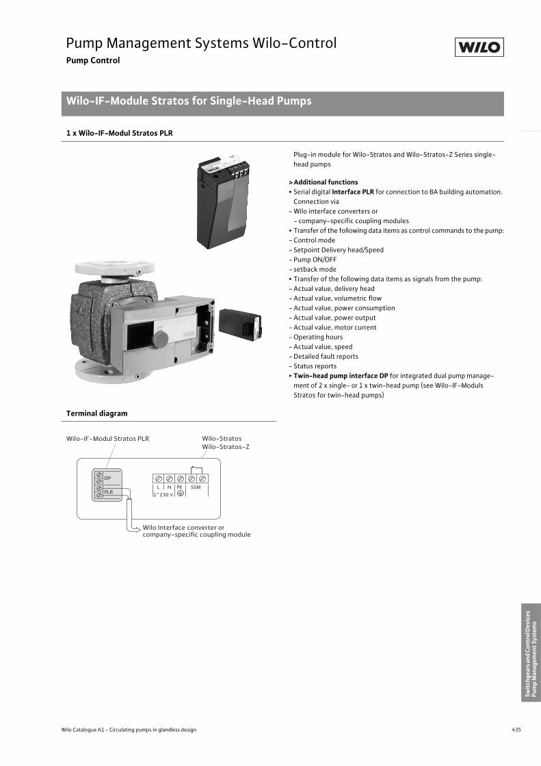
435
Pump Management Systems Wilo-ControlPump Control
Wilo-IF-Module Stratos for Single-Head Pumps
Wilo Catalogue A1 - Circulating pumps in glandless design
Hea
tin
g, A
ir-c
on
dit
ion
ing
, C
oo
ling
Po
tab
le w
ater
cir
cula
tio
nSo
lar
ther
mal
Serv
ice/
Acc
esso
ries
, Sys
tem
sSw
itch
gear
s an
d C
ontr
ol D
evic
es
Pum
p M
anag
emen
t Sy
stem
s
1 x Wilo-IF-Modul Stratos PLR
Plug-in module for Wilo-Stratos and Wilo-Stratos-Z Series single-
head pumps
> Additional functions• Serial digital Interface PLR for connection to BA building automation.
Connection via
- Wilo interface converters or
- company-specific coupling modules
• Transfer of the following data items as control commands to the pump:
- Control mode
- Setpoint Delivery head/Speed
- Pump ON/OFF
- setback mode
• Transfer of the following data items as signals from the pump:
- Actual value, delivery head
- Actual value, volumetric flow
- Actual value, power consumption
- Actual value, power output
- Actual value, motor current
- Operating hours
- Actual value, speed
- Detailed fault reports
- Status reports
• Twin-head pump interface DP for integrated dual pump manage-
ment of 2 x single- or 1 x twin-head pump (see Wilo-IF-Moduls
Stratos for twin-head pumps)
Terminal diagram
PLR
DP
L N PE SSM
1~230 V
Wilo-IF-Modul Stratos PLR
Wilo Interface converter orcompany-specific coupling module
Wilo-StratosWilo-Stratos-Z
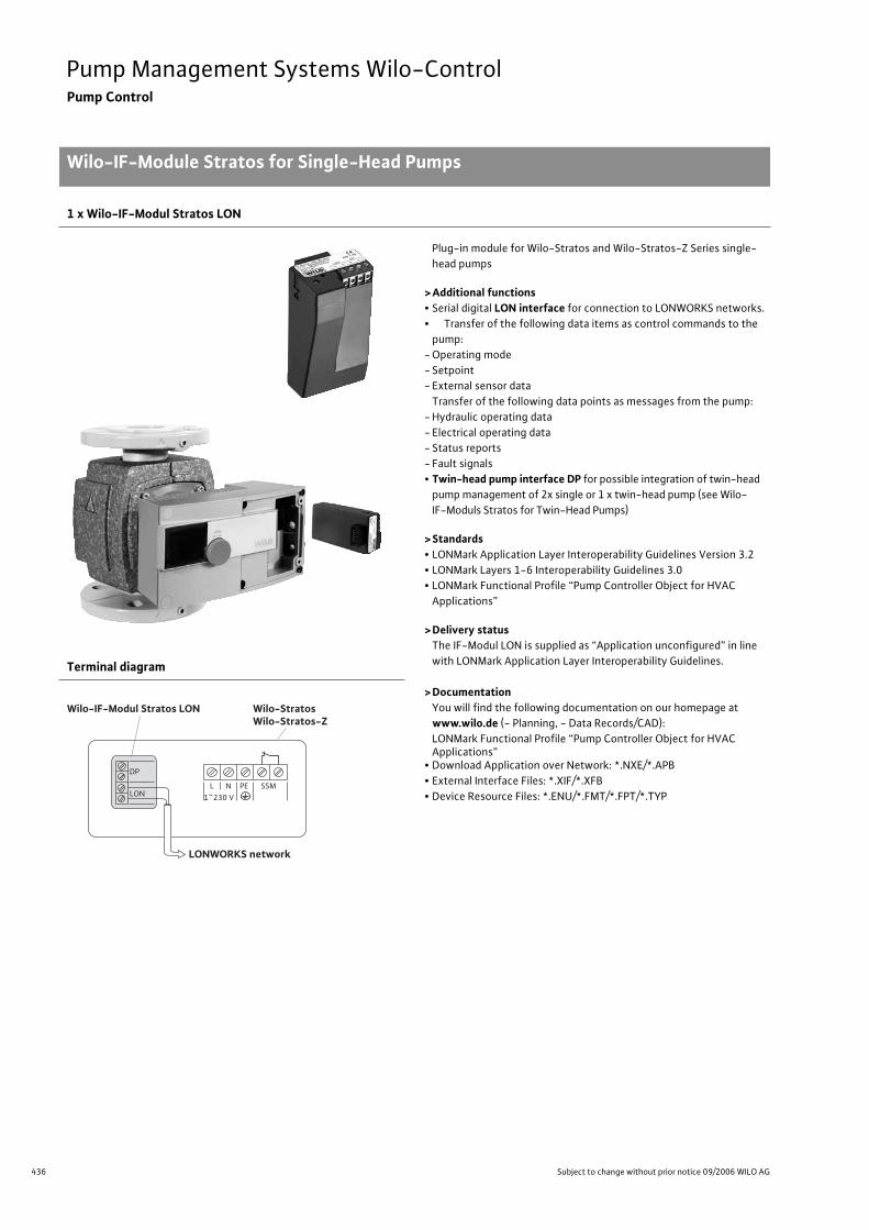
436 Subject to change without prior notice 09/2006 WILO AG
Pump Management Systems Wilo-ControlPump Control
Wilo-IF-Module Stratos for Single-Head Pumps
1 x Wilo-IF-Modul Stratos LON
Plug-in module for Wilo-Stratos and Wilo-Stratos-Z Series single-
head pumps
>Additional functions• Serial digital LON interface for connection to LONWORKS networks.
• Transfer of the following data items as control commands to the
pump:
- Operating mode
- Setpoint
- External sensor data
Transfer of the following data points as messages from the pump:
- Hydraulic operating data
- Electrical operating data
- Status reports
- Fault signals
• Twin-head pump interface DP for possible integration of twin-head
pump management of 2x single or 1 x twin-head pump (see Wilo-
IF-Moduls Stratos for Twin-Head Pumps)
>Standards• LONMark Application Layer Interoperability Guidelines Version 3.2
• LONMark Layers 1-6 Interoperability Guidelines 3.0
• LONMark Functional Profile “Pump Controller Object for HVAC
Applications”
>Delivery statusThe IF-Modul LON is supplied as “Application unconfigured” in line
with LONMark Application Layer Interoperability Guidelines.
>DocumentationYou will find the following documentation on our homepage at
www.wilo.de (- Planning, - Data Records/CAD):
LONMark Functional Profile “Pump Controller Object for HVAC Applications”
• Download Application over Network: *.NXE/*.APB
• External Interface Files: *.XIF/*.XFB
• Device Resource Files: *.ENU/*.FMT/*.FPT/*.TYP
Terminal diagram
LONWORKS network
LON
DP
L N PE SSM1~230 V
Wilo-StratosWilo-Stratos-Z
Wilo-IF-Modul Stratos LON
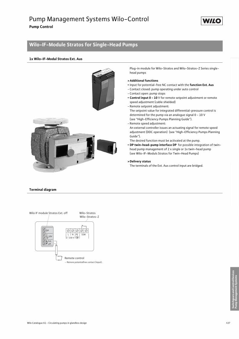
437
Pump Management Systems Wilo-ControlPump Control
Wilo-IF-Module Stratos for Single-Head Pumps
Wilo Catalogue A1 - Circulating pumps in glandless design
Hea
tin
g, A
ir-c
on
dit
ion
ing
, C
oo
ling
Po
tab
le w
ater
cir
cula
tio
nSo
lar
ther
mal
Serv
ice/
Acc
esso
ries
, Sys
tem
sSw
itch
gear
s an
d C
ontr
ol D
evic
es
Pum
p M
anag
emen
t Sy
stem
s
1x Wilo-IF-Modul Stratos Ext. Aus
Plug-in module for Wilo-Stratos and Wilo-Stratos-Z Series single-
head pumps
> Additional functions• Input for potential-free NC contact with the function Ext. Aus- Contact closed: pump operating under auto control
- Contact open: pump stops
• Control input 0 - 10 V for remote setpoint adjustment or remote
speed adjustment (cable shielded)
- Remote setpoint adjustment:
The setpoint value for integrated differential-pressure control is
determined for the pump via an analogue signal 0 - 10 V
(see “High-Efficiency Pumps Planning Guide”).
- Remote speed adjustment:
An external controller issues an actuating signal for remote speed
adjustment (DDC operation) (see “High-Efficiency Pumps Planning
Guide”).
The desired function must be activated at the pump.
• DP twin-head-pump interface DP for possible integration of twin-
head pump management of 2 x single or 1x twin-head pump
(see Wilo-IF-Moduls Stratos for Twin-Head Pumps)
> Delivery statusThe terminals of the Ext. Aus control input are bridged.
Terminal diagram
Ext.off
DP
L N PE SSM1~230 V
Wilo-StratosWilo-Stratos-Z
Wilo IF module Stratos Ext. off
0...10V
Remote control– Remore potentialfree contact (input):
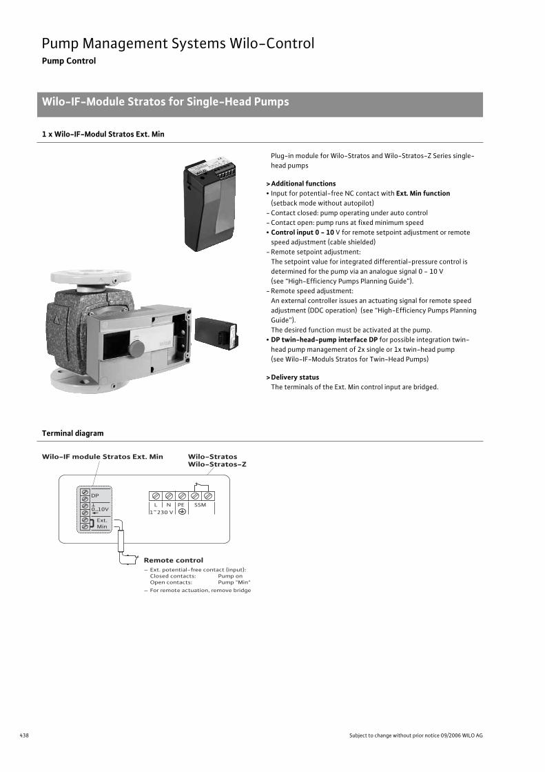
438 Subject to change without prior notice 09/2006 WILO AG
Pump Management Systems Wilo-ControlPump Control
Wilo-IF-Module Stratos for Single-Head Pumps
1 x Wilo-IF-Modul Stratos Ext. Min
Plug-in module for Wilo-Stratos and Wilo-Stratos-Z Series single-
head pumps
>Additional functions• Input for potential-free NC contact with Ext. Min function
(setback mode without autopilot)
- Contact closed: pump operating under auto control
- Contact open: pump runs at fixed minimum speed
• Control input 0 - 10 V for remote setpoint adjustment or remote
speed adjustment (cable shielded)
- Remote setpoint adjustment:
The setpoint value for integrated differential-pressure control is
determined for the pump via an analogue signal 0 - 10 V
(see “High-Efficiency Pumps Planning Guide”).
- Remote speed adjustment:
An external controller issues an actuating signal for remote speed
adjustment (DDC operation) (see “High-Efficiency Pumps Planning
Guide”).
The desired function must be activated at the pump.
• DP twin-head-pump interface DP for possible integration twin-
head pump management of 2x single or 1x twin-head pump
(see Wilo-IF-Moduls Stratos for Twin-Head Pumps)
>Delivery statusThe terminals of the Ext. Min control input are bridged.
Terminal diagram
Remote control– Ext. potential-free contact (input): Closed contacts: Pump on Open contacts: Pump "Min"
– For remote actuation, remove bridge
Ext.Min
DP
L N PE SSM1~230 V
Wilo-StratosWilo-Stratos-Z
Wilo-IF module Stratos Ext. Min
0...10V
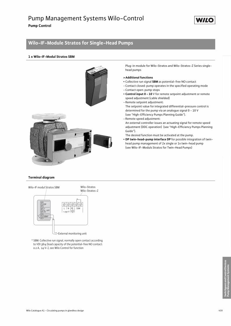
439
Pump Management Systems Wilo-ControlPump Control
Wilo-IF-Module Stratos for Single-Head Pumps
Wilo Catalogue A1 - Circulating pumps in glandless design
Hea
tin
g, A
ir-c
on
dit
ion
ing
, C
oo
ling
Po
tab
le w
ater
cir
cula
tio
nSo
lar
ther
mal
Serv
ice/
Acc
esso
ries
, Sys
tem
sSw
itch
gear
s an
d C
ontr
ol D
evic
es
Pum
p M
anag
emen
t Sy
stem
s
1 x Wilo-IF-Modul Stratos SBM
Plug-in module for Wilo-Stratos and Wilo-Stratos-Z Series single-
head pumps
> Additional functions• Collective run signal SBM as potential-free NO contact
- Contact closed: pump operates in the specified operating mode
- Contact open: pump stops
• Control input 0 - 10 V for remote setpoint adjustment or remote
speed adjustment (cable shielded)
- Remote setpoint adjustment:
The setpoint value for integrated differential-pressure control is
determined for the pump via an analogue signal 0 - 10 V
(see “High-Efficiency Pumps Planning Guide”).
- Remote speed adjustment:
An external controller issues an actuating signal for remote speed
adjustment (DDC operation) (see “High-Efficiency Pumps Planning
Guide”).
The desired function must be activated at the pump.
• DP twin-head-pump interface DP for possible integration of twin-
head pump management of 2x single or 1x twin-head pump
(see Wilo-IF-Moduls Stratos for Twin-Head Pumps)
Terminal diagram
SBM*
DP
L N PE SSM1~230 V
Wilo-IF modul Stratos SBM
0...10V
* SBM: Collective run signal, normally open contact according to VDI 3814 (load capacity of the potential-free NO contact: 0.2 A, 24 V~), see Wilo Control for function
External monitoring unit
Wilo-StratosWilo-Stratos-Z
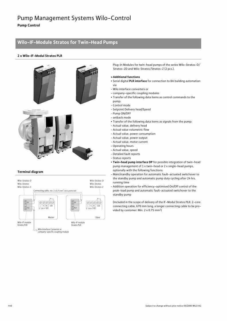
440 Subject to change without prior notice 09/2006 WILO AG
Pump Management Systems Wilo-ControlPump Control
Wilo-IF-Module Stratos for Twin-Head Pumps
2 x Wilo-IF-Modul Stratos PLR
Plug-in Modules for twin-head pumps of the series Wilo-Stratos-D/
Stratos-ZD and Wilo-Stratos/Stratos-Z (2 pcs.).
>Additional functions• Serial digital PLR interface for connection to BA building automation
via
- Wilo interface converters or
- company-specific coupling modules
• Transfer of the following data items as control commands to the
pump:
- Control mode
- Setpoint Delivery head/Speed
- Pump ON/OFF
- setback mode
• Transfer of the following data items as signals from the pump:
- Actual value, delivery head
- Actual value volumetric flow
- Actual value, power consumption
- Actual value, power output
- Actual value, motor current
- Operating hours
- Actual value, speed
- Detailed fault reports
- Status reports
• Twin-head pump interface DP for possible integration of twin-head
pump management of 1 x twin-head or 2 x single-head pumps,
optionally with the following functions:
- Main/standby operation for automatic fault-actuated switchover to
the standby pump and automatic pump duty cycling after 24 hrs.
running time
- Addition operation for efficiency-optimised On/Off control of the
peak-load pump and automatic fault-actuated switchover to the
standby pump
(Included in the scope of delivery of the IF-Modul Stratos PLR: 2-core
connecting cable, 670 mm long, a longer connecting cable to be pro-
vided by customer: Min. 2 x 0.75 mm2)
Terminal diagram
PLR
DP
L N PE SSM1~230 V
Wilo-Stratos-DWilo-StratosWilo-Stratos-Z
Wilo-Stratos-DWilo-StratosWilo-Stratos-Z
Wilo-IF module Stratos PLR
PLR
DP
Wilo Interface Converter orcompany-specific coupling module
Master
L N PE SSM1~230 V
Slave
Wilo-IF module Stratos PLR
Connecting cable, min. 2 x 0,75 mm2, lock-protected
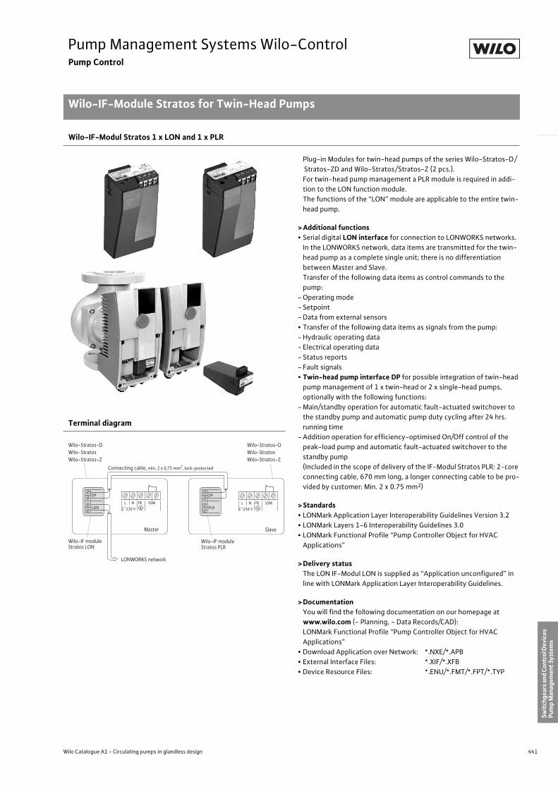
441
Pump Management Systems Wilo-ControlPump Control
Wilo-IF-Module Stratos for Twin-Head Pumps
Wilo Catalogue A1 - Circulating pumps in glandless design
Hea
tin
g, A
ir-c
on
dit
ion
ing
, C
oo
ling
Po
tab
le w
ater
cir
cula
tio
nSo
lar
ther
mal
Serv
ice/
Acc
esso
ries
, Sys
tem
sSw
itch
gear
s an
d C
ontr
ol D
evic
es
Pum
p M
anag
emen
t Sy
stem
s
Wilo-IF-Modul Stratos 1 x LON and 1 x PLR
Plug-in Modules for twin-head pumps of the series Wilo-Stratos-D/
Stratos-ZD and Wilo-Stratos/Stratos-Z (2 pcs.).
For twin-head pump management a PLR module is required in addi-
tion to the LON function module.
The functions of the “LON” module are applicable to the entire twin-
head pump.
> Additional functions• Serial digital LON interface for connection to LONWORKS networks.
In the LONWORKS network, data items are transmitted for the twin-
head pump as a complete single unit; there is no differentiation
between Master and Slave.
Transfer of the following data items as control commands to the
pump:
- Operating mode
- Setpoint
- Data from external sensors
• Transfer of the following data items as signals from the pump:
- Hydraulic operating data
- Electrical operating data
- Status reports
- Fault signals
• Twin-head pump interface DP for possible integration of twin-head
pump management of 1 x twin-head or 2 x single-head pumps,
optionally with the following functions:
- Main/standby operation for automatic fault-actuated switchover to
the standby pump and automatic pump duty cycling after 24 hrs.
running time
- Addition operation for efficiency-optimised On/Off control of the
peak-load pump and automatic fault-actuated switchover to the
standby pump
(Included in the scope of delivery of the IF-Modul Stratos PLR: 2-core
connecting cable, 670 mm long, a longer connecting cable to be pro-
vided by customer: Min. 2 x 0.75 mm2)
> Standards• LONMark Application Layer Interoperability Guidelines Version 3.2
• LONMark Layers 1-6 Interoperability Guidelines 3.0
• LONMark Functional Profile “Pump Controller Object for HVAC
Applications”
> Delivery statusThe LON IF-Modul LON is supplied as “Application unconfigured” in
line with LONMark Application Layer Interoperability Guidelines.
> DocumentationYou will find the following documentation on our homepage at
www.wilo.com (- Planning, - Data Records/CAD):
LONMark Functional Profile “Pump Controller Object for HVAC
Applications”
• Download Application over Network: *.NXE/*.APB
• External Interface Files: *.XIF/*.XFB
• Device Resource Files: *.ENU/*.FMT/*.FPT/*.TYP
Terminal diagram
LONWORKS network
LON
DP
L N PE SSM1~230 V
Wilo-Stratos-DWilo-StratosWilo-Stratos-Z
Wilo-Stratos-DWilo-StratosWilo-Stratos-Z
Wilo-IF module Stratos LON
PLR
DP
Master
L N PE SSM1~230 V
Slave
Wilo-IF module Stratos PLR
Connecting cable, min. 2 x 0,75 mm2, lock-protected
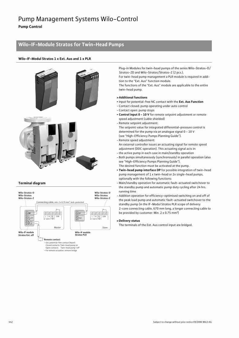
442 Subject to change without prior notice 09/2006 WILO AG
Pump Management Systems Wilo-ControlPump Control
Wilo-IF-Module Stratos for Twin-Head Pumps
Wilo-IF-Modul Stratos 1 x Ext. Aus and 1 x PLR
Plug-in Modules for twin-head pumps of the series Wilo-Stratos-D/
Stratos-ZD and Wilo-Stratos/Stratos-Z (2 pcs.).
For twin-head pump management a PLR module is required in addi-
tion to the “Ext. Aus” function module.
The functions of the “Ext. Aus” module are applicable to the entire
twin-head pump.
>Additional functions• Input for potential-free NC contact with the Ext. Aus Function- Contact closed: pump operating under auto control
- Contact open: pump stops
• Control input 0 - 10 V for remote setpoint adjustment or remote
speed adjustment (cable shielded)
- Remote setpoint adjustment:
The setpoint value for integrated differential-pressure control is
determined for the pump via an analogue signal 0 - 10 V
(see “High-Efficiency Pumps Planning Guide”).
- Remote speed adjustment:
An external controller issues an actuating signal for remote speed
adjustment (DDC operation). This actuating signal acts in:
- the active pump in each case in main/standby operation
- Both pumps simultaneously (synchronously) in parallel operation (also
see “High-Efficiency Pumps Planning Guide”).
The desired function must be activated at the pump.
• Twin-head pump interface DP for possible integration of twin-head
pump management of 1 x twin-head or 2x single-head pumps,
optionally with the following functions:
- Main/standby operation for automatic fault-actuated switchover to
the standby pump and automatic pump duty cycling after 24 hrs.
running time
- Addition operation for efficiency-optimised switching on and off of
the peak load pump and automatic fault-actuated switchover to the
standby pump (in the IF-Modul Stratos PLR scope of delivery:
2-core connecting cable, 670 mm long, a longer connecting cable to
be provided by customer: Min. 2 x 0.75 mm2)
>Delivery statusThe terminals of the Ext. Aus control input are bridged.
Terminal diagram
DP
L N PE SSM1~230 V
Wilo-Stratos-DWilo-StratosWilo-Stratos-Z
Wilo-Stratos-DWilo-StratosWilo-Stratos-Z
Wilo-IF module Stratos Ext. off
Master
PLR
DP
L N PE SSM1~230 V
Slave
Wilo-IF module Stratos PLR
Connecting cable, min. 2 x 0,75 mm2, lock-protected
Remote contact– Ext. potential-free contact (Input): Closed contacts: Twin-head pump on Open contacts: Twin-head pump "off"– For remote actuation, remove bridge
Ext.off
DP
0...10V
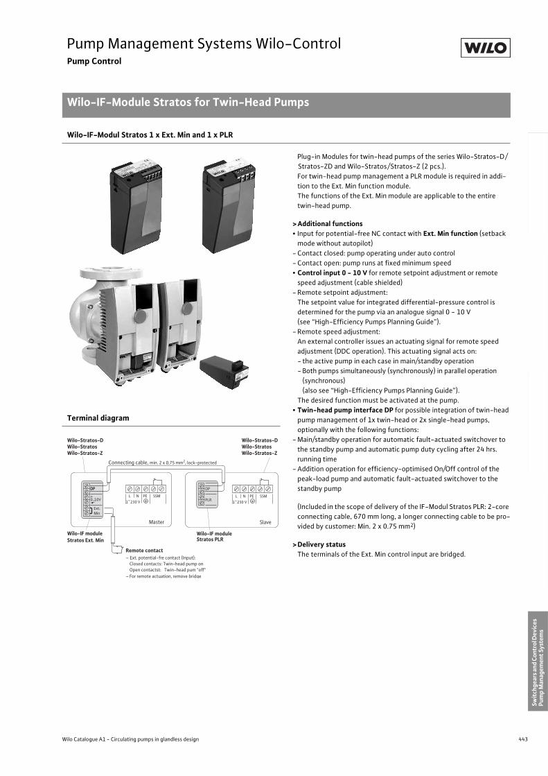
443
Pump Management Systems Wilo-ControlPump Control
Wilo-IF-Module Stratos for Twin-Head Pumps
Wilo Catalogue A1 - Circulating pumps in glandless design
Hea
tin
g, A
ir-c
on
dit
ion
ing
, C
oo
ling
Po
tab
le w
ater
cir
cula
tio
nSo
lar
ther
mal
Serv
ice/
Acc
esso
ries
, Sys
tem
sSw
itch
gear
s an
d C
ontr
ol D
evic
es
Pum
p M
anag
emen
t Sy
stem
s
Wilo-IF-Modul Stratos 1 x Ext. Min and 1 x PLR
Plug-in Modules for twin-head pumps of the series Wilo-Stratos-D/
Stratos-ZD and Wilo-Stratos/Stratos-Z (2 pcs.).
For twin-head pump management a PLR module is required in addi-
tion to the Ext. Min function module.
The functions of the Ext. Min module are applicable to the entire
twin-head pump.
> Additional functions• Input for potential-free NC contact with Ext. Min function (setback
mode without autopilot)
- Contact closed: pump operating under auto control
- Contact open: pump runs at fixed minimum speed
• Control input 0 - 10 V for remote setpoint adjustment or remote
speed adjustment (cable shielded)
- Remote setpoint adjustment:
The setpoint value for integrated differential-pressure control is
determined for the pump via an analogue signal 0 - 10 V
(see “High-Efficiency Pumps Planning Guide”).
- Remote speed adjustment:
An external controller issues an actuating signal for remote speed
adjustment (DDC operation). This actuating signal acts on:
- the active pump in each case in main/standby operation
- Both pumps simultaneously (synchronously) in parallel operation
(synchronous)
(also see “High-Efficiency Pumps Planning Guide”).
The desired function must be activated at the pump.
• Twin-head pump interface DP for possible integration of twin-head
pump management of 1x twin-head or 2x single-head pumps,
optionally with the following functions:
- Main/standby operation for automatic fault-actuated switchover to
the standby pump and automatic pump duty cycling after 24 hrs.
running time
- Addition operation for efficiency-optimised On/Off control of the
peak-load pump and automatic fault-actuated switchover to the
standby pump
(Included in the scope of delivery of the IF-Modul Stratos PLR: 2-core
connecting cable, 670 mm long, a longer connecting cable to be pro-
vided by customer: Min. 2 x 0.75 mm2)
> Delivery statusThe terminals of the Ext. Min control input are bridged.
Terminal diagram
DP
L N PE SSM1~230 V
Wilo-Stratos-DWilo-StratosWilo-Stratos-Z
Wilo-Stratos-DWilo-StratosWilo-Stratos-Z
Wilo-IF module Stratos Ext. Min
Master
PLR
DP
L N PE SSM1~230 V
Slave
Wilo-IF module Stratos PLR
Connecting cable, min. 2 x 0,75 mm2, lock-protected
Remote contact– Ext. potential-fre contact (Input): Closed contacts: Twin-head pump on Open contactst: Twin-head pum "off"– For remote actuation, remove bridge
Ext.Min
DP
0...10V
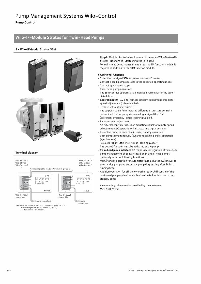
444 Subject to change without prior notice 09/2006 WILO AG
Pump Management Systems Wilo-ControlPump Control
Wilo-IF-Module Stratos for Twin-Head Pumps
2 x Wilo-IF-Modul Stratos SBM
Plug-in Modules for twin-head pumps of the series Wilo-Stratos-D/
Stratos-ZD and Wilo-Stratos/Stratos-Z (2 pcs.).
For twin-head pump management an extra SBM function module is
required in addition to the SBM function module.
>Additional functions• Collective run signal SBM as potential-free NO contact
- Contact closed: pump operates in the specified operating mode
- Contact open: pump stops
- Twin-head pump operation:
The SBM contact operates as an individual run signal for the asso-
ciated drive.
• Control input 0 - 10 V for remote setpoint adjustment or remote
speed adjustment (cable shielded)
- Remote setpoint adjustment:
The setpoint value for integrated differential-pressure control is
determined for the pump via an analogue signal 0 - 10 V
(see “High-Efficiency Pumps Planning Guide”).
- Remote speed adjustment:
An external controller issues an actuating signal for remote speed
adjustment (DDC operation). This actuating signal acts on:
- the active pump in each case in main/standby operation
- Both pumps simultaneously (synchronously) in parallel operation
(synchronous)
(also see “High-Efficiency Pumps Planning Guide”).
The desired function must be activated at the pump.
• Twin-head pump interface DP for possible integration of twin-head
pump management of 1x twin-head or 2x single-head pumps,
optionally with the following functions:
- Main/standby operation for automatic fault-actuated switchover to
the standby pump and automatic pump duty cycling after 24 hrs.
running time
- Addition operation for efficiency-optimised On/Off control of the
peak-load pump and automatic fault-actuated switchover to the
standby pump
A connecting cable must be provided by the customer:
Min. 2 x 0.75 mm2
Terminal diagram
0...10V L N PE SSM
1~230 V
Wilo-Stratos-DWilo-StratosWilo-Stratos-Z
Wilo-Stratos-DWilo-StratosWilo-Stratos-Z
Wilo-IF-Modul Stratos SBM
Master
L N PE SSM1~230 V
Slave
Wilo-IF-Modul Stratos SBM
Connecting cable, min. 2 x 0,75 mm2, lock-protected
External control unit
SBM*
DP
External control unit
*SBM: Collective run signals, NO contact in compliance with VDI 3814 (Switch rating of volt-free NO contact 1A, 250 V~) Function see Wilo-TOP-Control
0...10V 0...10V
SBM*
DP
0...10V
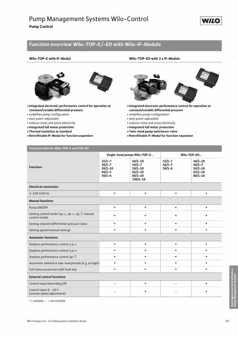
445
Pump Management Systems Wilo-ControlPump Control
Function overview Wilo-TOP-E/-ED with Wilo-IF-Module
Wilo Catalogue A1 - Circulating pumps in glandless design
Hea
tin
g, A
ir-c
on
dit
ion
ing
, C
oo
ling
Po
tab
le w
ater
cir
cula
tio
nSo
lar
ther
mal
Serv
ice/
Acc
esso
ries
, Sys
tem
sSw
itch
gear
s an
d C
ontr
ol D
evic
es
Pum
p M
anag
emen
t Sy
stem
s
Wilo-TOP-E with IF-Modul Wilo-TOP-ED with 2 x IF-Moduls
> Integrated electronic performance control for operation at constant/variable differential pressure
• simplifies pump configuration
• duty point-adjustable
• reduces noise and saves electricity
> Integrated full motor protection> Thermal insulation as standard> Retrofittable IF-Modul for function expansion
> Integrated electronic performance control for operation at constant/variable differential pressure
• simplifies pump configuration
• duty point-adjustable
• reduces noise and saves electricity
> Integrated full motor protection> Twin-head pump switchover valve> Retrofittable IF-Modul for function expansion
Function table for Wilo-TOP-E and TOP-ED
Function:
Single-head pumps Wilo-TOP-E... Wilo-TOP-ED...
25/1-730/1-730/1-1040/1-450/1-6
40/1-1050/1-750/1-1065/1-1080/1-10100/1-10
32/1-740/1-750/1-6
40/1-1050/1-750/1-1065/1-1080/1-10
Electrical connection
1~230 V/50 Hz • • • •
Manual functions
Pump ON/OFF • • • •
Setting control mode ( p-c, p-v, p-T, manual control mode)
• • • •
Setting setpoint differential-pressure value • • • •
Setting speed (manual setting) • • • •
Automatic functions
Stepless performance control p-c • • • •
Stepless performance control p-v • • • •
Stepless performance control p-T • • • •
Automatic setback in low-load periods (e.g. at night) • • • •
Full motor protection with fault trip • • • •
External control functions
Control input Overriding Off – • – •
Control input 0 - 10 V (remote speed adjustment)
– • – •
• = available, – = not available
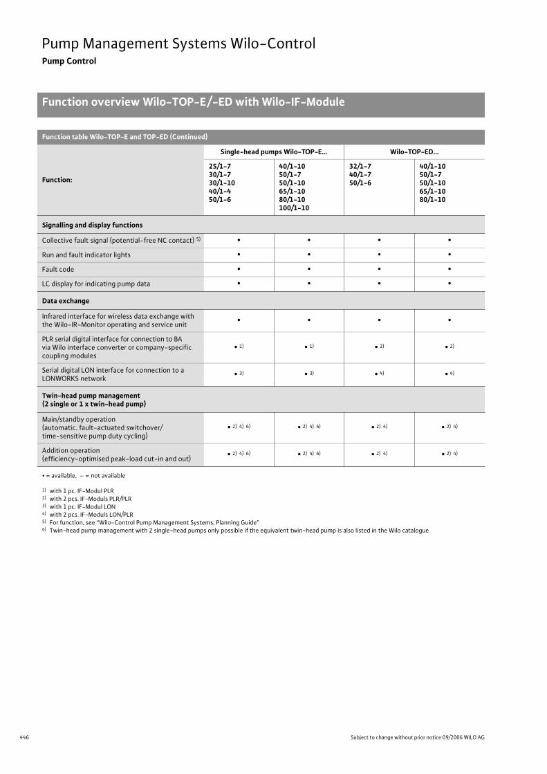
446 Subject to change without prior notice 09/2006 WILO AG
Pump Management Systems Wilo-ControlPump Control
Function overview Wilo-TOP-E/-ED with Wilo-IF-Module
Function table Wilo-TOP-E and TOP-ED (Continued)
Function:
Single-head pumps Wilo-TOP-E... Wilo-TOP-ED...
25/1-730/1-730/1-1040/1-450/1-6
40/1-1050/1-750/1-1065/1-1080/1-10100/1-10
32/1-740/1-750/1-6
40/1-1050/1-750/1-1065/1-1080/1-10
Signalling and display functions
Collective fault signal (potential-free NC contact) 5) • • • •
Run and fault indicator lights • • • •
Fault code • • • •
LC display for indicating pump data • • • •
Data exchange
Infrared interface for wireless data exchange with the Wilo-IR-Monitor operating and service unit
• • • •
PLR serial digital interface for connection to BA via Wilo interface converter or company-specific coupling modules
• 1) • 1) • 2) • 2)
Serial digital LON interface for connection to a LONWORKS network
• 3) • 3) • 4) • 4)
Twin-head pump management(2 single or 1 x twin-head pump)
Main/standby operation (automatic. fault-actuated switchover/time-sensitive pump duty cycling)
• 2) 4) 6) • 2) 4) 6) • 2) 4) • 2) 4)
Addition operation (efficiency-optimised peak-load cut-in and out)
• 2) 4) 6) • 2) 4) 6) • 2) 4) • 2) 4)
• = available, – = not available
1) with 1 pc. IF-Modul PLR2) with 2 pcs. IF-Moduls PLR/PLR3) with 1 pc. IF-Modul LON4) with 2 pcs. IF-Moduls LON/PLR5) For function, see “Wilo-Control Pump Management Systems, Planning Guide”6) Twin-head pump management with 2 single-head pumps only possible if the equivalent twin-head pump is also listed in the Wilo catalogue
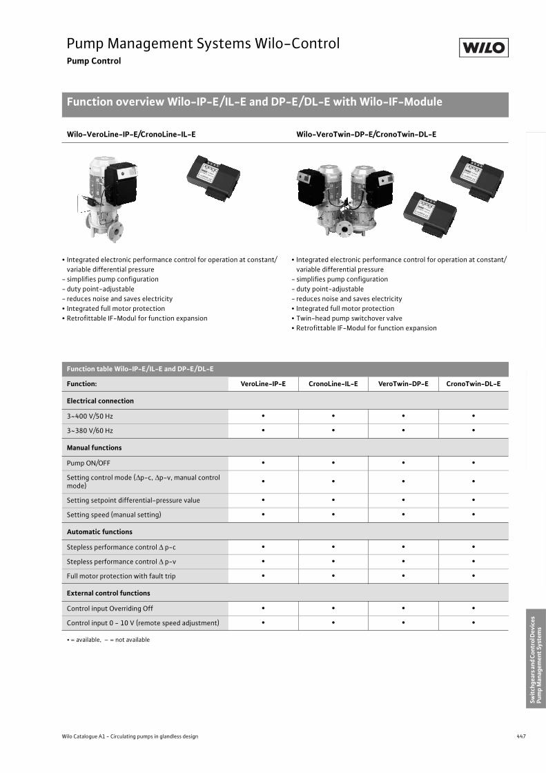
447
Pump Management Systems Wilo-ControlPump Control
Function overview Wilo-IP-E/IL-E and DP-E/DL-E with Wilo-IF-Module
Wilo Catalogue A1 - Circulating pumps in glandless design
Hea
tin
g, A
ir-c
on
dit
ion
ing
, C
oo
ling
Po
tab
le w
ater
cir
cula
tio
nSo
lar
ther
mal
Serv
ice/
Acc
esso
ries
, Sys
tem
sSw
itch
gear
s an
d C
ontr
ol D
evic
es
Pum
p M
anag
emen
t Sy
stem
s
Wilo-VeroLine-IP-E/CronoLine-IL-E Wilo-VeroTwin-DP-E/CronoTwin-DL-E
• Integrated electronic performance control for operation at constant/
variable differential pressure
- simplifies pump configuration
- duty point-adjustable
- reduces noise and saves electricity
• Integrated full motor protection
• Retrofittable IF-Modul for function expansion
• Integrated electronic performance control for operation at constant/
variable differential pressure
- simplifies pump configuration
- duty point-adjustable
- reduces noise and saves electricity
• Integrated full motor protection
• Twin-head pump switchover valve
• Retrofittable IF-Modul for function expansion
Function table Wilo-IP-E/IL-E and DP-E/DL-E
Function: VeroLine-IP-E CronoLine-IL-E VeroTwin-DP-E CronoTwin-DL-E
Electrical connection
3~400 V/50 Hz • • • •
3~380 V/60 Hz • • • •
Manual functions
Pump ON/OFF • • • •
Setting control mode ( p-c, p-v, manual control mode)
• • • •
Setting setpoint differential-pressure value • • • •
Setting speed (manual setting) • • • •
Automatic functions
Stepless performance control p-c • • • •
Stepless performance control p-v • • • •
Full motor protection with fault trip • • • •
External control functions
Control input Overriding Off • • • •
Control input 0 - 10 V (remote speed adjustment) • • • •
• = available, – = not available
448 Subject to change without prior notice 09/2006 WILO AG
Pump Management Systems Wilo-ControlPump Control
Function overview Wilo-IP-E/IL-E and DP-E/DL-E with Wilo-IF-Module
Function table Wilo-IP-E/IL-E and DP-E/DL-E (Continued)
Function: VeroLine-IP-E CronoLine-IL-E VeroTwin-DP-E CronoTwin-DL-E
Signalling and display functions
Collective fault signal • • • •
Collective run signal • • • •
Fault light • • • •
IR communication indicator light • • • •
Fault code • • • •
LC display for indicating pump data • • • •
Data exchange
Infrared interface for wireless data exchange with the Wilo-IR-Monitor operating and service unit
• • • •
PLR serial digital interface for connection to BA via Wilo interface converter or company-specific coupling modules
• 1) • 1) • 1) • 2)
Serial digital LON interface for connection to a LONWORKS network
• 3) • 3) • 3) • 4)
Twin-head pump management(2 x single-head or 1 x twin-head pump)
Main/standby operation (automatic fault-actuated switchover/time-sensitive pump duty cycling)
• • 2) 4) 5) • • 2) 4)
Addition operation (peak-load cut-in and out) • • 2) 4) 5) • • 2) 4)
• = available, – = not available
1) with 1 pc. IF-Modul PLR2) with 2 pc. IF-Moduls PLR/PLR3) with 1 pc. IF-Modul LON 4) with 2 pc. IF-Moduls LON/PLR5) Twin-head pump management with 2 single-head pumps only possible if the equivalent twin-head pump is also listed in the Wilo catalogue
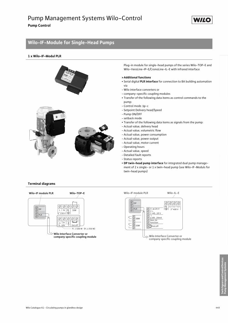
449
Pump Management Systems Wilo-ControlPump Control
Wilo-IF-Module for Single-Head Pumps
Wilo Catalogue A1 - Circulating pumps in glandless design
Hea
tin
g, A
ir-c
on
dit
ion
ing
, C
oo
ling
Po
tab
le w
ater
cir
cula
tio
nSo
lar
ther
mal
Serv
ice/
Acc
esso
ries
, Sys
tem
sSw
itch
gear
s an
d C
ontr
ol D
evic
es
Pum
p M
anag
emen
t Sy
stem
s
1 x Wilo-IF-Modul PLR
Plug-in module for single-head pumps of the series Wilo-TOP-E and
Wilo-VeroLine-IP-E/CronoLine-IL-E with infrared interface
> Additional functions• Serial digital PLR interface for connection to BA building automation
via
- Wilo interface converters or
- company-specific coupling modules
• Transfer of the following data items as control commands to the
pump:
- Control mode p-c
- Setpoint Delivery head/Speed
- Pump ON/OFF
- setback mode
• Transfer of the following data items as signals from the pump:
- Actual value, delivery head
- Actual value, volumetric flow
- Actual value, power consumption
- Actual value, power output
- Actual value, motor current
- Operating hours
- Actual value, speed
- Detailed fault reports
- Status reports
• DP twin-head pump interface for integrated dual pump manage-
ment of 2 x single- or 1 x twin-head pump (see Wilo-IF-Moduls for
twin-head pumps)
Terminal diagrams
PLR
DP L N PE SSM
1~230 V
Wilo-TOP-EWilo-IF module PLR
Wilo Interface Converter orcompany specific coupling module
0...10V In
Ext.off
P1 ≥ 500 W (P2 ≥ 350 W)
+24V
PLR
DP
PE L1 L2 L33~400 V
Wilo-IL-EWilo-IF module PLR
Wilo Interface Converter orcompany specific coupling module
SBM
SSM
3 +24 V21 0...10 V
0/4...20mAAux, nofunction
Ext.off
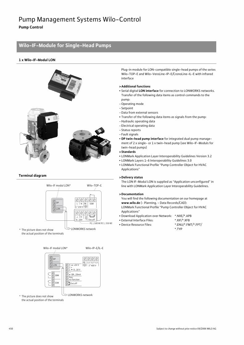
450 Subject to change without prior notice 09/2006 WILO AG
Pump Management Systems Wilo-ControlPump Control
Wilo-IF-Module for Single-Head Pumps
1 x Wilo-IF-Modul LON
Plug-in module for LON-compatible single-head pumps of the series
Wilo-TOP-E and Wilo-VeroLine-IP-E/CronoLine-IL-E with infrared
interface
>Additional functions• Serial digital LON interface for connection to LONWORKS networks.
Transfer of the following data items as control commands to the
pump:
- Operating mode
- Setpoint
- Data from external sensors
• Transfer of the following data items as signals from the pump:
- Hydraulic operating data
- Electrical operating data
- Status reports
- Fault signals
• DP twin-head pump interface for integrated dual pump manage-
ment of 2 x single- or 1 x twin-head pump (see Wilo-IF-Moduls for
twin-head pumps)
>Standards• LONMark Application Layer Interoperability Guidelines Version 3.2
• LONMark Layers 1-6 Interoperability Guidelines 3.0
• LONMark Functional Profile “Pump Controller Object for HVAC
Applications”
>Delivery statusThe LON IF-Modul LON is supplied as “Application unconfigured” in
line with LONMark Application Layer Interoperability Guidelines.
>DocumentationYou will find the following documentation on our homepage at
www.wilo.de (- Planning, - Data Records/CAD):
LONMark Functional Profile “Pump Controller Object for HVAC
Applications”
• Download Application over Network: *.NXE/*.APB
• External Interface Files: *.XIF/*.XFB
• Device Resource Files: *.ENU/*.FMT/*.FPT/
*.TYP
Terminal diagram
LON
DP L N PE SSM1~230 V
Wilo-TOP-EWilo-IF modul LON*
LONWORKS network
0...10V In
Ext.off+24V
* The picture does not showthe actual position of the terminals
P1 500 W (P2 350 W)
LON
DP
PE L1 L2 L33~400 V
Wilo-IP-E/IL-EWilo-IF modul LON*
LONWORKS network
SBM
SSM
3 +24 V21 0...10 V
0/4...20mAAux, no function
Ext.off
* The picture does not showthe actual position of the terminals
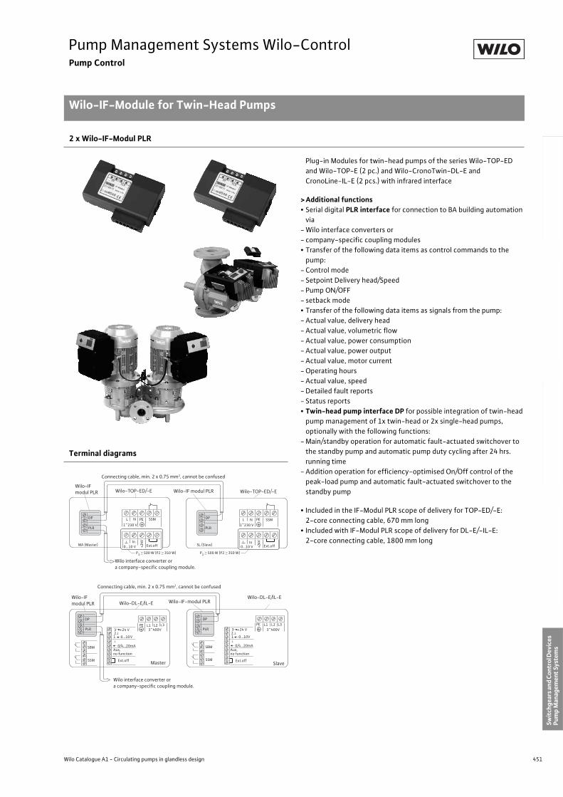
451
Pump Management Systems Wilo-ControlPump Control
Wilo-IF-Module for Twin-Head Pumps
Wilo Catalogue A1 - Circulating pumps in glandless design
Hea
tin
g, A
ir-c
on
dit
ion
ing
, C
oo
ling
Po
tab
le w
ater
cir
cula
tio
nSo
lar
ther
mal
Serv
ice/
Acc
esso
ries
, Sys
tem
sSw
itch
gear
s an
d C
ontr
ol D
evic
es
Pum
p M
anag
emen
t Sy
stem
s
2 x Wilo-IF-Modul PLR
Plug-in Modules for twin-head pumps of the series Wilo-TOP-ED
and Wilo-TOP-E (2 pc.) and Wilo-CronoTwin-DL-E and
CronoLine-IL-E (2 pcs.) with infrared interface
> Additional functions• Serial digital PLR interface for connection to BA building automation
via
- Wilo interface converters or
- company-specific coupling modules
• Transfer of the following data items as control commands to the
pump:
- Control mode
- Setpoint Delivery head/Speed
- Pump ON/OFF
- setback mode
• Transfer of the following data items as signals from the pump:
- Actual value, delivery head
- Actual value, volumetric flow
- Actual value, power consumption
- Actual value, power output
- Actual value, motor current
- Operating hours
- Actual value, speed
- Detailed fault reports
- Status reports
• Twin-head pump interface DP for possible integration of twin-head
pump management of 1x twin-head or 2x single-head pumps,
optionally with the following functions:
- Main/standby operation for automatic fault-actuated switchover to
the standby pump and automatic pump duty cycling after 24 hrs.
running time
- Addition operation for efficiency-optimised On/Off control of the
peak-load pump and automatic fault-actuated switchover to the
standby pump
• Included in the IF-Modul PLR scope of delivery for TOP-ED/-E:
2-core connecting cable, 670 mm long
• Included with IF-Modul PLR scope of delivery for DL-E/-IL-E:
2-core connecting cable, 1800 mm long
Terminal diagrams
PLR
DP L N PE 1~230 V
0...10 V In
PLR
DP L N PE
1~230 V
0...10 V In
SSMSSM
Wilo-IF modul PLR Wilo-TOP-ED/-E Wilo-IF modul PLR
Wilo interface converter or a company-specific coupling module.
P1 500 W (P2 350 W) P1
500 W (P2 350 W)
Ext.offExt.off+24V
+24VMA (Master) SL (Slave)
Wilo-TOP-ED/-E
Connecting cable, min. 2 x 0.75 mm2, cannot be confused
Master Slave
3 +24 V21 0...10V
0/4...20mAAux, no function
23 +24 V
0/4...20mA
PE L1 L2 L3 PE L1 L2 L33~400V 3~400V
DP
PLR
DP
PLR
SBM
SSM
SBM
SSM
1 0...10V
Connecting cable, min. 2 x 0.75 mm2, cannot be confused
Wilo-IF modul PLR Wilo-DL-E/IL-E Wilo-IF-modul PLR
Wilo interface converter or a company-specific coupling module.
Wilo-DL-E/IL-E
Ext.offExt.off
Aux, no function
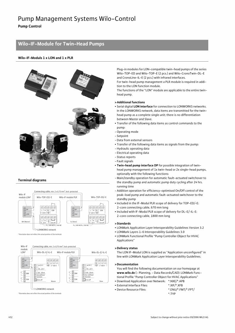
452 Subject to change without prior notice 09/2006 WILO AG
Pump Management Systems Wilo-ControlPump Control
Wilo-IF-Module for Twin-Head Pumps
Wilo-IF-Moduls 1 x LON and 1 x PLR
Plug-in modules for LON-compatible twin-head pumps of the series
Wilo-TOP-ED and Wilo-TOP-E (2 pcs.) and Wilo-CronoTwin-DL-E
and CronoLine-IL-E (2 pcs.) with infrared interfaces.
For twin-head pump management a PLR module is required in addi-
tion to the LON function module.
The functions of the “LON” module are applicable to the entire twin-
head pump.
>Additional functions• Serial digital LON interface for connection to LONWORKS networks.
In the LONWORKS network, data items are transmitted for the twin-
head pump as a complete single unit; there is no differentiation
between Master and Slave.
• Transfer of the following data items as control commands to the
pump:
- Operating mode
- Setpoint
- Data from external sensors
• Transfer of the following data items as signals from the pump:
- Hydraulic operating data
- Electrical operating data
- Status reports
- Fault signals
• Twin-head pump interface DP for possible integration of twin-
head pump management of 1x twin-head or 2x single-head pumps,
optionally with the following functions:
- Main/standby operation for automatic fault-actuated switchover to
the standby pump and automatic pump duty cycling after 24 hrs.
running time
- Addition operation for efficiency-optimised On/Off control of the
peak-load pump and automatic fault-actuated switchover to the
standby pump
• Included in the IF-Modul PLR scope of delivery for TOP-ED/-E:
2-core connecting cable, 670 mm long
• Included with IF-Modul PLR scope of delivery for DL-E/-IL-E:
2-core connecting cable, 1800 mm long
>Standards• LONMark Application Layer Interoperability Guidelines Version 3.2
• LONMark Layers 1-6 Interoperability Guidelines 3.0
• LONMark Functional Profile “Pump Controller Object for HVAC
Applications”
>Delivery statusThe LON IF-Modul LON is supplied as “Application unconfigured” in
line with LONMark Application Layer Interoperability Guidelines.
>DocumentationYou will find the following documentation on our homepage at
www.wilo.de (- Planning, - Data Records/CAD): LONMark Func-
tional Profile “Pump Controller Object for HVAC Applications”
• Download Application over Network: *.NXE/*.APB
• External Interface Files: *.XIF/*.XFB
• Device Resource Files: *.ENU/*.FMT/*.FPT/
*.TYP
Terminal diagrams
LON
DP L N PE SSM
1~230 V
Wilo-TOP-ED/-EWilo-IFmodule LON*
LONWORKS network
0...10 V In
Ext.off+24V
PLR
DP L N PE SSM
1~230 V
0...10 V Ext.off
Connecting cable, min. 2 x 0,75 mm2, lock-protected
Wilo-IF module PLR Wilo-TOP-ED/-E
MA (Master) SL (Slave)
* Illustration does not reflect the actual position of the terminals
In
+24V
P1 500 W (P2 350 W) P1 500 W (P2 350 W)
LON
DP
PE L1 L2 L33~400 V
Wilo-DL-E/-IL-E
Wilo-IFmoduleLON*
LONWORKS network
SBM
SSM
3 +24 V21 0...10 V
0/4...20mAAux,without function
Ext.offMaster
PLR
DP
PE L1 L2 L33~400 V
Wilo-IF module PLR
SBM
SSM
3 +24 V21 0...10 V
0/4...20mAAux, without function
Ext.offSlave
Connecting cable, min. 2 x 0,75 mm2, lock-protected
Wilo-DL-E/-IL-E
* Illustration does not reflect the actual position of the terminals
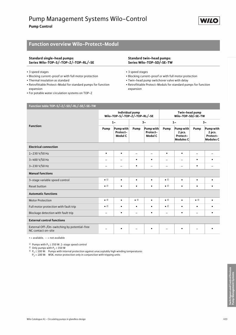
453
Pump Management Systems Wilo-ControlPump Control
Function overview Wilo-Protect-Modul
Wilo Catalogue A1 - Circulating pumps in glandless design
Hea
tin
g, A
ir-c
on
dit
ion
ing
, C
oo
ling
Po
tab
le w
ater
cir
cula
tio
nSo
lar
ther
mal
Serv
ice/
Acc
esso
ries
, Sys
tem
sSw
itch
gear
s an
d C
ontr
ol D
evic
es
Pum
p M
anag
emen
t Sy
stem
s
Standard single-head pumps:Series Wilo-TOP-S/-TOP-Z/-TOP-RL/-SE
Standard twin-head pumps:Series Wilo-TOP-SD/-SE-TW
• 3 speed stages
• Blocking current-proof or with full motor protection
• Thermal insulation as standard
• Retrofittable Protect-Modul for standard pumps for function
expansion
• For potable water circulation systems on TOP-Z
• 3 speed stages
• Blocking current-proof or with full motor protection
• Twin-head pump switchover valve with delay
• Retrofittable Protect-Moduls for standard pumps for function
expansion
Function table TOP-S/-Z/-SD/-RL/-SE/-SE-TW
Function:
Individual pumpWilo-TOP-S/-TOP-Z/-TOP-RL/-SE
Twin-head pumpWilo-TOP-SD/-SE-TW
1~ 3~ 1~ 3~
Pump Pump with Protect-Modul C
Pump Pump with Protect-Modul C
Pump Pump with 2 pcs.
Protect-Modules C
Pump Pump with 2 pcs.
Protect-Modules C
Electrical connection
1~230 V/50 Hz • • – – • • – –
3~400 V/50 Hz – – • • – – • •
3~230 V/50 Hz – – • – – – • –
Manual functions
3-stage variable speed control • 1) • • • • 1) • • •
Reset button • 2) • • • • 2) • • •
Automatic functions
Motor Protection • 3) • • 3) • • 3) • • 3) •
Full motor protection with fault trip • 2) • • • • 2) • • •
Blockage detection with fault trip – • – • – • – •
External control functions
External Off-/On-switching by potential-free NC contact on-site
– • – • – • – •
• = available, – = not available
1) Pumps with P2 350 W: 2-stage speed control2) Only pumps with P2 350 W3) P2 100 W: Pumps with internal protection against unacceptably high winding temperatures
P2 = 180 W: WSK, motor protection only in conjunction with tripping units
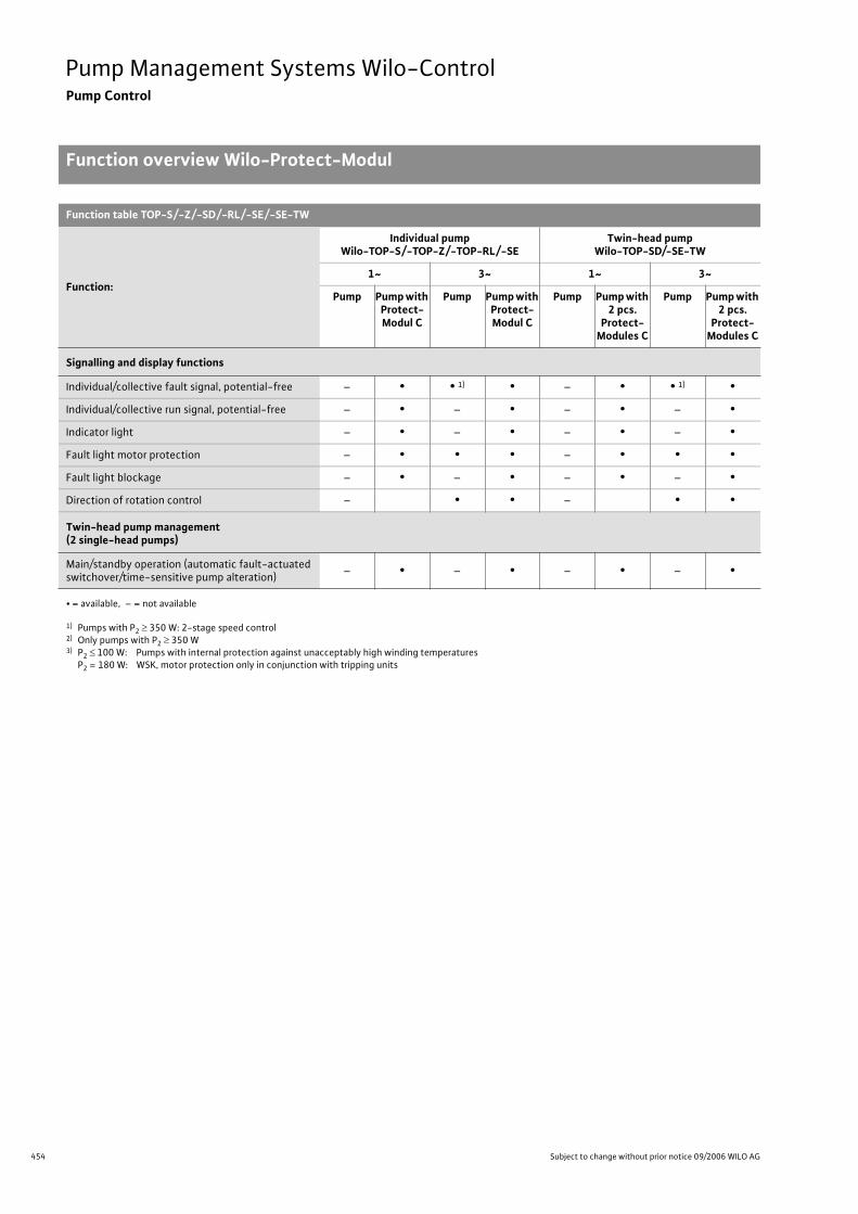
454 Subject to change without prior notice 09/2006 WILO AG
Pump Management Systems Wilo-ControlPump Control
Function overview Wilo-Protect-Modul
Signalling and display functions
Individual/collective fault signal, potential-free – • • 1) • – • • 1) •
Individual/collective run signal, potential-free – • – • – • – •
Indicator light – • – • – • – •
Fault light motor protection – • • • – • • •
Fault light blockage – • – • – • – •
Direction of rotation control – • • – • •
Twin-head pump management (2 single-head pumps)
Main/standby operation (automatic fault-actuated switchover/time-sensitive pump alteration)
– • – • – • – •
• = available, – = not available
1) Pumps with P2 350 W: 2-stage speed control2) Only pumps with P2 350 W3) P2 100 W: Pumps with internal protection against unacceptably high winding temperatures
P2 = 180 W: WSK, motor protection only in conjunction with tripping units
Function table TOP-S/-Z/-SD/-RL/-SE/-SE-TW
Function:
Individual pumpWilo-TOP-S/-TOP-Z/-TOP-RL/-SE
Twin-head pumpWilo-TOP-SD/-SE-TW
1~ 3~ 1~ 3~
Pump Pump with Protect-Modul C
Pump Pump with Protect-Modul C
Pump Pump with 2 pcs.
Protect-Modules C
Pump Pump with 2 pcs.
Protect-Modules C
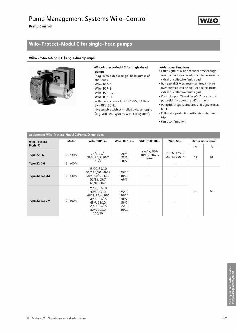
455
Pump Management Systems Wilo-ControlPump Control
Wilo-Protect-Modul C for single-head pumps
Wilo Catalogue A1 - Circulating pumps in glandless design
Hea
tin
g, A
ir-c
on
dit
ion
ing
, C
oo
ling
Po
tab
le w
ater
cir
cula
tio
nSo
lar
ther
mal
Serv
ice/
Acc
esso
ries
, Sys
tem
sSw
itch
gear
s an
d C
ontr
ol D
evic
es
Pum
p M
anag
emen
t Sy
stem
s
Wilo-Protect-Modul C (single-head pumps)
>Wilo-Protect-Modul C for single-head pumpsPlug-in module for single-head pumps of
the series
Wilo-TOP-S
Wilo-TOP-Z
Wilo-TOP-RL
Wilo-TOP-SE
with mains connection 1~230 V, 50 Hz or
3~400 V, 50 Hz.
Not suitable with controlled voltage supply
(e.g. Wilo-AS-System, Wilo-CR-System).
>Additional functions• Fault signal SSM as potential-free change-
over contact, can be adjusted to be an indi-
vidual or collective fault signal
• Run signal SBM as potential-free change-
over contact, can be adjusted to be an indi-
vidual or collective fault signal
• Control input “Overriding Off” by external
potential-free contact (NC contact)
• Pump blockage is detected and signalised as
fault.
• Full motor protection with integrated fault
trip
• Fault confirmation
Assignment Wilo-Protect-Modul C/Pump, Dimensions
Wilo-Protect-Modul C
Motor Wilo-TOP-S... Wilo-TOP-Z... Wilo-TOP-RL… Wilo-SE… Dimensions [mm]
a5 l5
Type 22 EM 1~230 V 25/5, 25/730/4, 30/5, 30/7
40/4
20/425/630/7
25/7.5, 30/430/6.5, 30/7.5
40/4
110-N, 125-N150-N, 200-N 27 61
Type 22 DM 3~400 V – –
Type 32-52 EM 1~230 V
25/10, 30/1040/7, 40/10, 40/1550/4, 50/7, 50/10
50/15, 65/765/10, 80/7
25/1030/1040/7
– –
28 63
Type 32-52 DM 3~400 V
25/10, 30/1040/7, 40/10
40/15, 50/4, 50/750/10, 50/1565/7, 65/10
65/13, 65/1580/7, 80/10
100/10
25/1030/1040/750/7
65/1080/10
– –
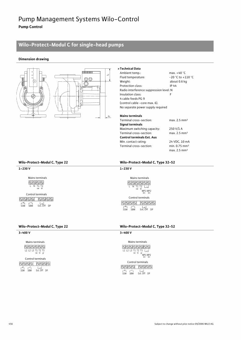
456 Subject to change without prior notice 09/2006 WILO AG
Pump Management Systems Wilo-ControlPump Control
Wilo-Protect-Modul C for single-head pumps
Dimension drawing
>Technical DataAmbient temp.: max. +40 °C
Fluid temperature: -20 °C to +110 °C
Weight: about 0.6 kg
Protection class: IP 44
Radio interference suppression level: N
Insulation class: F
4 cable feeds PG 9
(control cable -core max. 6).
No separate power supply required
Mains terminalsTerminal cross-section: max. 2.5 mm²
Signal terminalsMaximum switching capacity: 250 V/1 A
Terminal cross-section: max. 2.5 mm²
Control terminals Ext. AusMin. contact rating: 24 VDC, 10 mA
Terminal cross-section: min. 0.75 mm²
max. 2.5 mm²
Wilo-Protect-Modul C, Type 22 Wilo-Protect-Modul C, Type 32-52
1~230 V 1~230 V
Wilo-Protect-Modul C, Type 22 Wilo-Protect-Modul C, Type 32-52
3~400 V 3~400 V
a5
l 5
L N T1sw
T2bl
SSM SBM DPExt. Off
Mains terminals
Control terminals
L N T1sw
T2bl
SSM SBM DPExt. Off
MP1 MP2ws ws
Mains terminals
Control terminals
L3 T1 sw
L1 L2 T2 br
T3 gr
SSM SBM DP Ext. Off
Mains terminals
Control terminals
SSM SBM DP Ext. Off
L3 T1 sw
L1 L2 T2 br
T3 gr
MP1 MP2 ws ws
Mains terminals
Control terminals
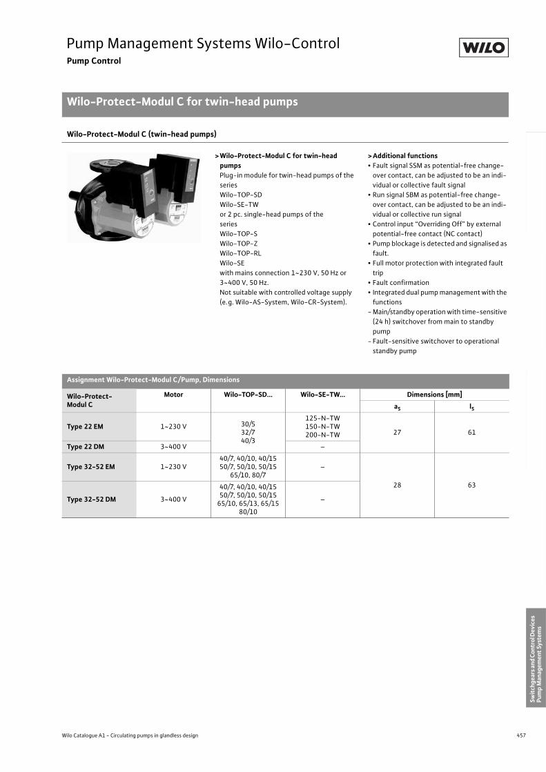
457
Pump Management Systems Wilo-ControlPump Control
Wilo-Protect-Modul C for twin-head pumps
Wilo Catalogue A1 - Circulating pumps in glandless design
Hea
tin
g, A
ir-c
on
dit
ion
ing
, C
oo
ling
Po
tab
le w
ater
cir
cula
tio
nSo
lar
ther
mal
Serv
ice/
Acc
esso
ries
, Sys
tem
sSw
itch
gear
s an
d C
ontr
ol D
evic
es
Pum
p M
anag
emen
t Sy
stem
s
Wilo-Protect-Modul C (twin-head pumps)
>Wilo-Protect-Modul C for twin-head pumpsPlug-in module for twin-head pumps of the
series
Wilo-TOP-SD
Wilo-SE-TW
or 2 pc. single-head pumps of the
series
Wilo-TOP-S
Wilo-TOP-Z
Wilo-TOP-RL
Wilo-SE
with mains connection 1~230 V, 50 Hz or
3~400 V, 50 Hz.
Not suitable with controlled voltage supply
(e.g. Wilo-AS-System, Wilo-CR-System).
>Additional functions• Fault signal SSM as potential-free change-
over contact, can be adjusted to be an indi-
vidual or collective fault signal
• Run signal SBM as potential-free change-
over contact, can be adjusted to be an indi-
vidual or collective run signal
• Control input “Overriding Off” by external
potential-free contact (NC contact)
• Pump blockage is detected and signalised as
fault.
• Full motor protection with integrated fault
trip
• Fault confirmation
• Integrated dual pump management with the
functions
- Main/standby operation with time-sensitive
(24 h) switchover from main to standby
pump
- Fault-sensitive switchover to operational
standby pump
Assignment Wilo-Protect-Modul C/Pump, Dimensions
Wilo-Protect-Modul C
Motor Wilo-TOP-SD... Wilo-SE-TW... Dimensions [mm]
a5 l5
Type 22 EM 1~230 V 30/532/740/3
125-N-TW150-N-TW200-N-TW 27 61
Type 22 DM 3~400 V –
Type 32-52 EM 1~230 V40/7, 40/10, 40/1550/7, 50/10, 50/15
65/10, 80/7–
28 63
Type 32-52 DM 3~400 V
40/7, 40/10, 40/1550/7, 50/10, 50/15
65/10, 65/13, 65/1580/10
–
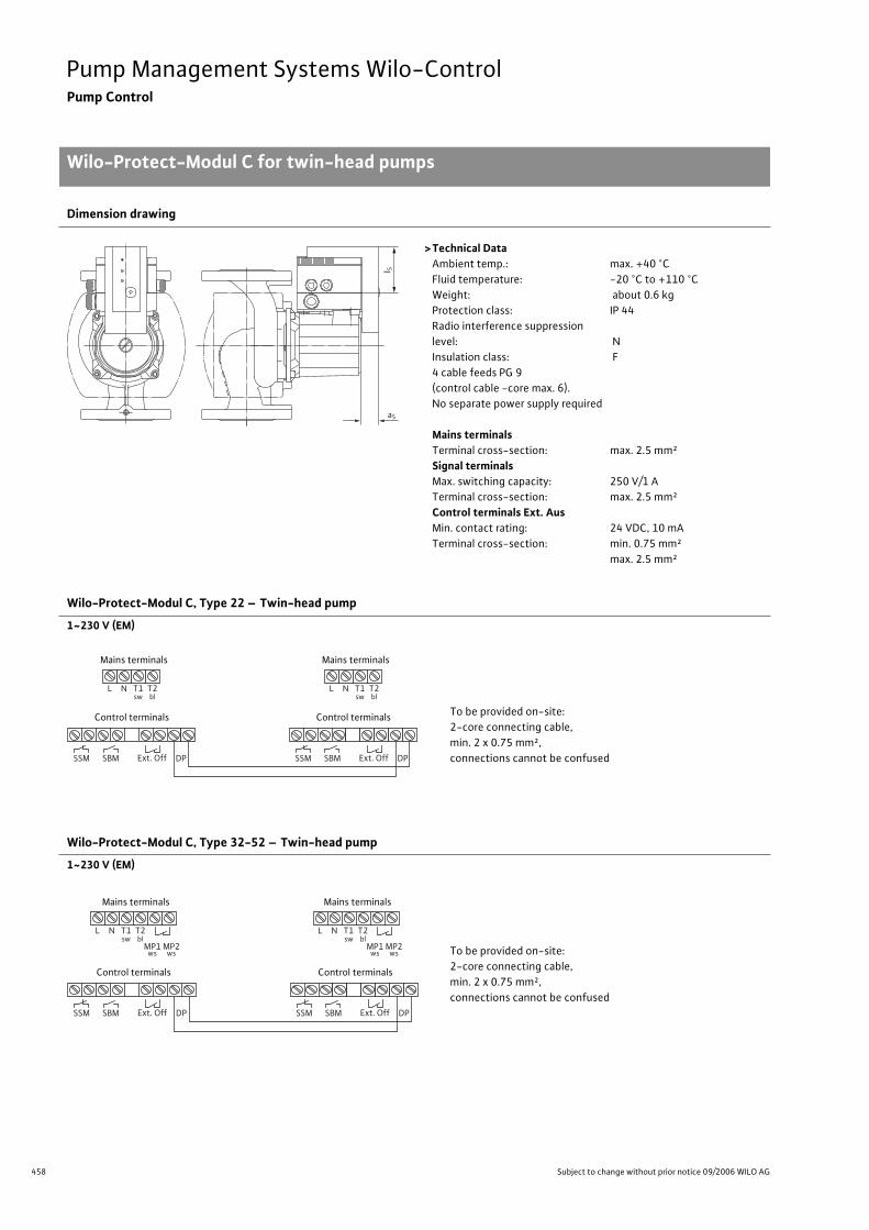
458 Subject to change without prior notice 09/2006 WILO AG
Pump Management Systems Wilo-ControlPump Control
Wilo-Protect-Modul C for twin-head pumps
Dimension drawing
>Technical DataAmbient temp.: max. +40 °C
Fluid temperature: -20 °C to +110 °C
Weight: about 0.6 kg
Protection class: IP 44
Radio interference suppression
level: N
Insulation class: F
4 cable feeds PG 9
(control cable -core max. 6).
No separate power supply required
Mains terminalsTerminal cross-section: max. 2.5 mm²
Signal terminalsMax. switching capacity: 250 V/1 A
Terminal cross-section: max. 2.5 mm²
Control terminals Ext. AusMin. contact rating: 24 VDC, 10 mA
Terminal cross-section: min. 0.75 mm²
max. 2.5 mm²
Wilo-Protect-Modul C, Type 22 – Twin-head pump
1~230 V (EM)
Wilo-Protect-Modul C, Type 32-52 – Twin-head pump
1~230 V (EM)
a5
l 5
L N T1sw
T2bl
SSM SBM DPExt. Off
L N T1sw
T2bl
SSM SBM DPExt. Off
Mains terminals
Control terminals
Mains terminals
Control terminals To be provided on-site:
2-core connecting cable,
min. 2 x 0.75 mm²,
connections cannot be confused
L N T1sw
T2bl
SSM SBM DPExt. Off
MP1 MP2ws ws
L N T1sw
T2bl
SSM SBM DPExt. Off
MP1 MP2ws ws
Mains terminals
Control terminals
Mains terminals
Control terminals
To be provided on-site:
2-core connecting cable,
min. 2 x 0.75 mm²,
connections cannot be confused
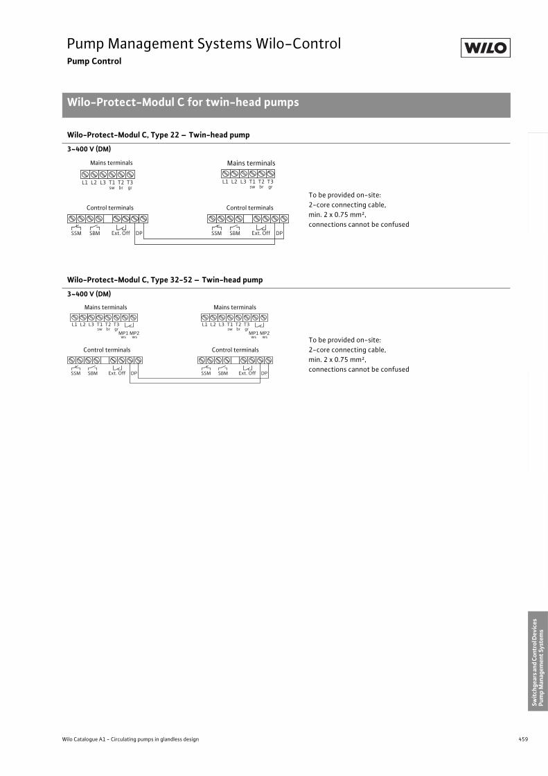
459
Pump Management Systems Wilo-ControlPump Control
Wilo-Protect-Modul C for twin-head pumps
Wilo Catalogue A1 - Circulating pumps in glandless design
Hea
tin
g, A
ir-c
on
dit
ion
ing
, C
oo
ling
Po
tab
le w
ater
cir
cula
tio
nSo
lar
ther
mal
Serv
ice/
Acc
esso
ries
, Sys
tem
sSw
itch
gear
s an
d C
ontr
ol D
evic
es
Pum
p M
anag
emen
t Sy
stem
s
Wilo-Protect-Modul C, Type 22 – Twin-head pump
3~400 V (DM)
Wilo-Protect-Modul C, Type 32-52 – Twin-head pump
3~400 V (DM)
SSM SBM DP Ext. Off SSM SBM DP Ext. Off
L3 T1 sw
L1 L2 T2 br
T3 gr
L3 T1 sw
L1 L2 T2 br
T3 gr
Mains terminals
Control terminals
Mains terminals
Control terminals
To be provided on-site:
2-core connecting cable,
min. 2 x 0.75 mm²,
connections cannot be confused
SSM SBM DP Ext. Off
L3 T1 sw
L1 L2 T2 br
T3 gr
MP1 MP2 ws ws
SSM SBM DP Ext. Off
L3 T1 sw
L1 L2 T2 br
T3 gr
MP1 MP2 ws ws
Mains terminals
Control terminals
Mains terminals
Control terminals
To be provided on-site:
2-core connecting cable,
min. 2 x 0.75 mm²,
connections cannot be confused
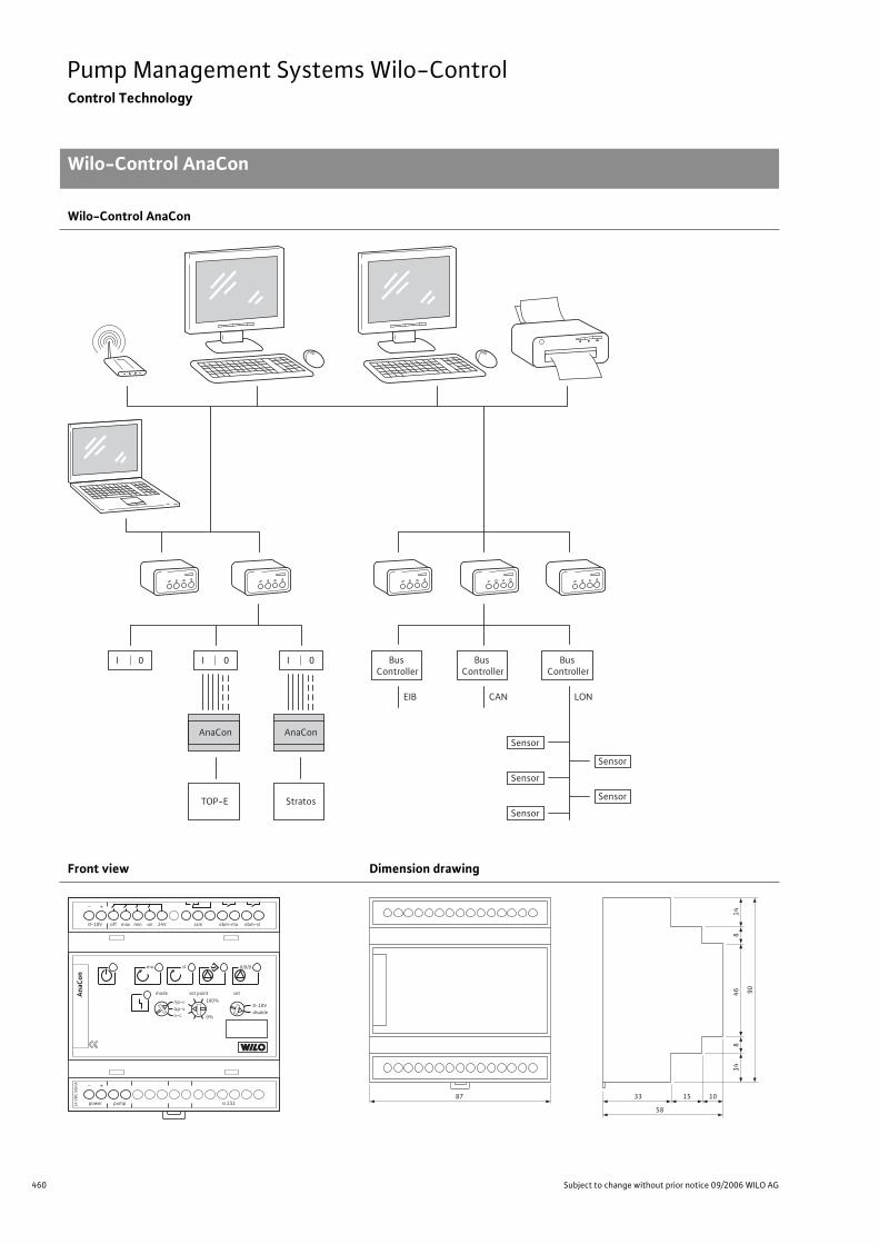
460 Subject to change without prior notice 09/2006 WILO AG
Pump Management Systems Wilo-ControlControl Technology
Wilo-Control AnaCon
Wilo-Control AnaCon
Front view Dimension drawing
I 0 Bus
Controller
EIB
Bus
Controller
CAN
Bus
Controller
AnaCon AnaCon
TOP-E Stratos
LON
I 0 I 0
Sensor
Sensor
Sensor
Sensor
Sensor
ma
0-10V off max min on 24V ssm ebm-ma ebm-sl
+-
mode
p-c
p-v
n-c
set pointAna
Con
100%
0%
0-10V
disable
set
sl 0/0/0
power
+-
pump rs 23224
VD
C 5
0m
A
14
46 90
87 33
58
15 10
14
88
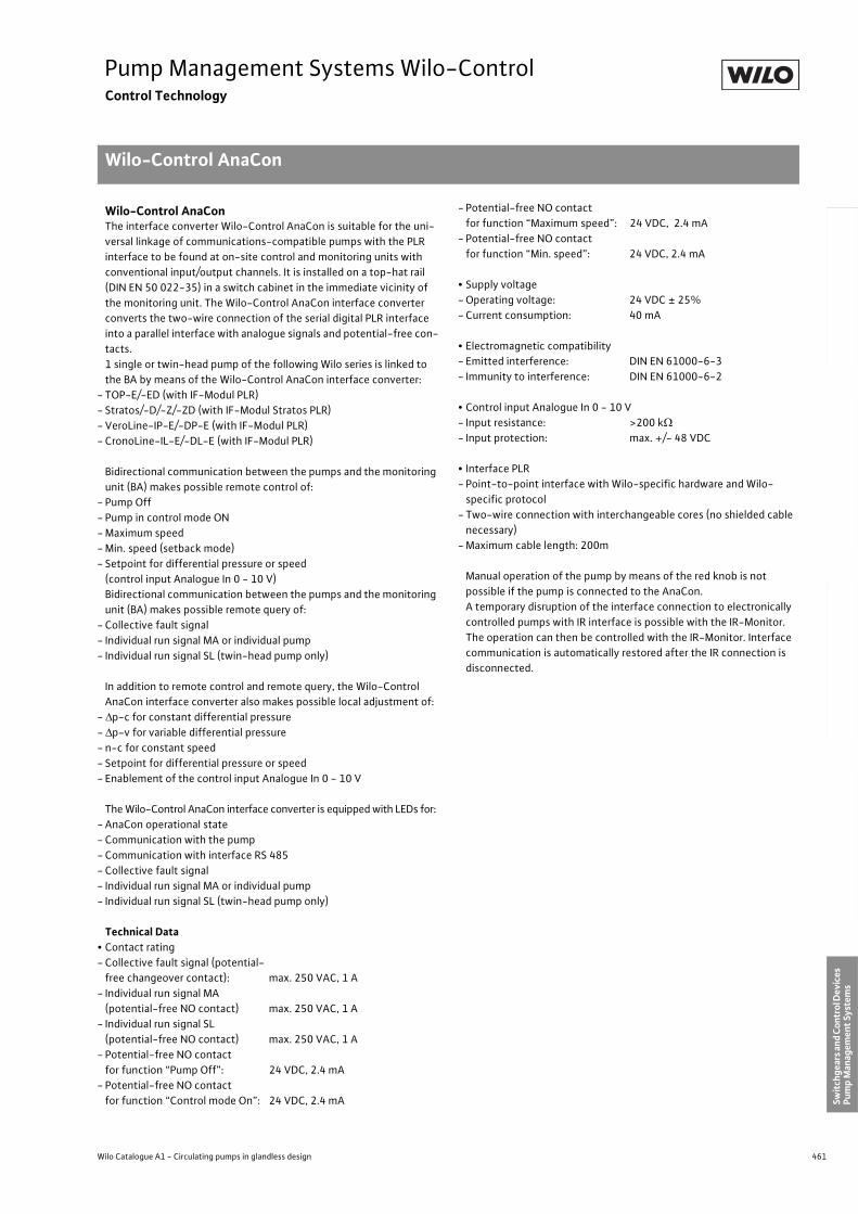
461
Pump Management Systems Wilo-ControlControl Technology
Wilo-Control AnaCon
Wilo Catalogue A1 - Circulating pumps in glandless design
Hea
tin
g, A
ir-c
on
dit
ion
ing
, C
oo
ling
Po
tab
le w
ater
cir
cula
tio
nSo
lar
ther
mal
Serv
ice/
Acc
esso
ries
, Sys
tem
sSw
itch
gear
s an
d C
ontr
ol D
evic
es
Pum
p M
anag
emen
t Sy
stem
s
Wilo-Control AnaConThe interface converter Wilo-Control AnaCon is suitable for the uni-
versal linkage of communications-compatible pumps with the PLR
interface to be found at on-site control and monitoring units with
conventional input/output channels. It is installed on a top-hat rail
(DIN EN 50 022-35) in a switch cabinet in the immediate vicinity of
the monitoring unit. The Wilo-Control AnaCon interface converter
converts the two-wire connection of the serial digital PLR interface
into a parallel interface with analogue signals and potential-free con-
tacts.
1 single or twin-head pump of the following Wilo series is linked to
the BA by means of the Wilo-Control AnaCon interface converter:
- TOP-E/-ED (with IF-Modul PLR)
- Stratos/-D/-Z/-ZD (with IF-Modul Stratos PLR)
- VeroLine-IP-E/-DP-E (with IF-Modul PLR)
- CronoLine-IL-E/-DL-E (with IF-Modul PLR)
Bidirectional communication between the pumps and the monitoring
unit (BA) makes possible remote control of:
- Pump Off
- Pump in control mode ON
- Maximum speed
- Min. speed (setback mode)
- Setpoint for differential pressure or speed
(control input Analogue In 0 - 10 V)
Bidirectional communication between the pumps and the monitoring
unit (BA) makes possible remote query of:
- Collective fault signal
- Individual run signal MA or individual pump
- Individual run signal SL (twin-head pump only)
In addition to remote control and remote query, the Wilo-Control
AnaCon interface converter also makes possible local adjustment of:
- p-c for constant differential pressure
- p-v for variable differential pressure
- n-c for constant speed
- Setpoint for differential pressure or speed
- Enablement of the control input Analogue In 0 - 10 V
The Wilo-Control AnaCon interface converter is equipped with LEDs for:
- AnaCon operational state
- Communication with the pump
- Communication with interface RS 485
- Collective fault signal
- Individual run signal MA or individual pump
- Individual run signal SL (twin-head pump only)
Technical Data• Contact rating
- Collective fault signal (potential-
free changeover contact): max. 250 VAC, 1 A
- Individual run signal MA
(potential-free NO contact) max. 250 VAC, 1 A
- Individual run signal SL
(potential-free NO contact) max. 250 VAC, 1 A
- Potential-free NO contact
for function “Pump Off”: 24 VDC, 2.4 mA
- Potential-free NO contact
for function “Control mode On”: 24 VDC, 2.4 mA
- Potential-free NO contact
for function “Maximum speed”: 24 VDC, 2.4 mA
- Potential-free NO contact
for function “Min. speed”: 24 VDC, 2.4 mA
• Supply voltage
- Operating voltage: 24 VDC ± 25%
- Current consumption: 40 mA
• Electromagnetic compatibility
- Emitted interference: DIN EN 61000-6-3
- Immunity to interference: DIN EN 61000-6-2
• Control input Analogue In 0 - 10 V
- Input resistance: >200 k
- Input protection: max. +/- 48 VDC
• Interface PLR
- Point-to-point interface with Wilo-specific hardware and Wilo-
specific protocol
- Two-wire connection with interchangeable cores (no shielded cable
necessary)
- Maximum cable length: 200m
Manual operation of the pump by means of the red knob is not
possible if the pump is connected to the AnaCon.
A temporary disruption of the interface connection to electronically
controlled pumps with IR interface is possible with the IR-Monitor.
The operation can then be controlled with the IR-Monitor. Interface
communication is automatically restored after the IR connection is
disconnected.
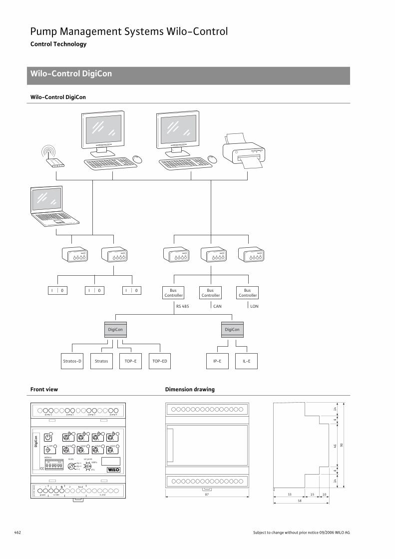
462 Subject to change without prior notice 09/2006 WILO AG
Pump Management Systems Wilo-ControlControl Technology
Wilo-Control DigiCon
Wilo-Control DigiCon
Front view Dimension drawing
I 0 Bus
Controller
RS 485
Bus
Controller
CAN
Bus
Controller
DigiCon
Stratos-D Stratos
DigiCon
IP-E IL-ETOP-E TOP-ED
LON
I 0 I 0
4321
RSNON
65
pump 1 pump 2 pump 3 pump 4
mode
p-c
p-v
n-c
set pointaddress
Dig
iCon
100%
0%
rs 485
1
1
2 3 4
power
+-
rs 485
a b BaudZ
rs 232
0/0/0
2
0/0/0
3
0/0/0
4
0/0/0
24
VD
C 5
0m
A
14
46 90
87 33
58
15 10
14
88
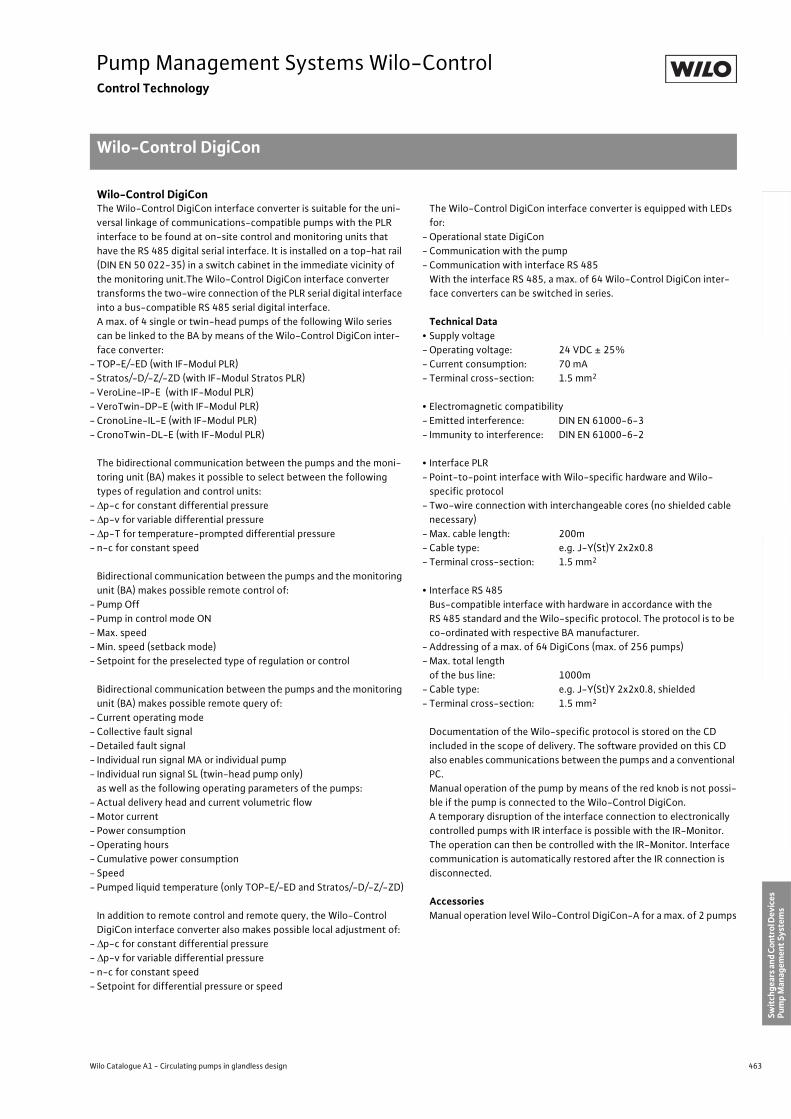
463
Pump Management Systems Wilo-ControlControl Technology
Wilo-Control DigiCon
Wilo Catalogue A1 - Circulating pumps in glandless design
Hea
tin
g, A
ir-c
on
dit
ion
ing
, C
oo
ling
Po
tab
le w
ater
cir
cula
tio
nSo
lar
ther
mal
Serv
ice/
Acc
esso
ries
, Sys
tem
sSw
itch
gear
s an
d C
ontr
ol D
evic
es
Pum
p M
anag
emen
t Sy
stem
s
Wilo-Control DigiConThe Wilo-Control DigiCon interface converter is suitable for the uni-
versal linkage of communications-compatible pumps with the PLR
interface to be found at on-site control and monitoring units that
have the RS 485 digital serial interface. It is installed on a top-hat rail
(DIN EN 50 022-35) in a switch cabinet in the immediate vicinity of
the monitoring unit.The Wilo-Control DigiCon interface converter
transforms the two-wire connection of the PLR serial digital interface
into a bus-compatible RS 485 serial digital interface.
A max. of 4 single or twin-head pumps of the following Wilo series
can be linked to the BA by means of the Wilo-Control DigiCon inter-
face converter:
- TOP-E/-ED (with IF-Modul PLR)
- Stratos/-D/-Z/-ZD (with IF-Modul Stratos PLR)
- VeroLine-IP-E (with IF-Modul PLR)
- VeroTwin-DP-E (with IF-Modul PLR)
- CronoLine-IL-E (with IF-Modul PLR)
- CronoTwin-DL-E (with IF-Modul PLR)
The bidirectional communication between the pumps and the moni-
toring unit (BA) makes it possible to select between the following
types of regulation and control units:
- p-c for constant differential pressure
- p-v for variable differential pressure
- p-T for temperature-prompted differential pressure
- n-c for constant speed
Bidirectional communication between the pumps and the monitoring
unit (BA) makes possible remote control of:
- Pump Off
- Pump in control mode ON
- Max. speed
- Min. speed (setback mode)
- Setpoint for the preselected type of regulation or control
Bidirectional communication between the pumps and the monitoring
unit (BA) makes possible remote query of:
- Current operating mode
- Collective fault signal
- Detailed fault signal
- Individual run signal MA or individual pump
- Individual run signal SL (twin-head pump only)
as well as the following operating parameters of the pumps:
- Actual delivery head and current volumetric flow
- Motor current
- Power consumption
- Operating hours
- Cumulative power consumption
- Speed
- Pumped liquid temperature (only TOP-E/-ED and Stratos/-D/-Z/-ZD)
In addition to remote control and remote query, the Wilo-Control
DigiCon interface converter also makes possible local adjustment of:
- p-c for constant differential pressure
- p-v for variable differential pressure
- n-c for constant speed
- Setpoint for differential pressure or speed
The Wilo-Control DigiCon interface converter is equipped with LEDs
for:
- Operational state DigiCon
- Communication with the pump
- Communication with interface RS 485
With the interface RS 485, a max. of 64 Wilo-Control DigiCon inter-
face converters can be switched in series.
Technical Data• Supply voltage
- Operating voltage: 24 VDC ± 25%
- Current consumption: 70 mA
- Terminal cross-section: 1.5 mm2
• Electromagnetic compatibility
- Emitted interference: DIN EN 61000-6-3
- Immunity to interference: DIN EN 61000-6-2
• Interface PLR
- Point-to-point interface with Wilo-specific hardware and Wilo-
specific protocol
- Two-wire connection with interchangeable cores (no shielded cable
necessary)
- Max. cable length: 200m
- Cable type: e.g. J-Y(St)Y 2x2x0.8
- Terminal cross-section: 1.5 mm2
• Interface RS 485
Bus-compatible interface with hardware in accordance with the
RS 485 standard and the Wilo-specific protocol. The protocol is to be
co-ordinated with respective BA manufacturer.
- Addressing of a max. of 64 DigiCons (max. of 256 pumps)
- Max. total length
of the bus line: 1000m
- Cable type: e.g. J-Y(St)Y 2x2x0.8, shielded
- Terminal cross-section: 1.5 mm2
Documentation of the Wilo-specific protocol is stored on the CD
included in the scope of delivery. The software provided on this CD
also enables communications between the pumps and a conventional
PC.
Manual operation of the pump by means of the red knob is not possi-
ble if the pump is connected to the Wilo-Control DigiCon.
A temporary disruption of the interface connection to electronically
controlled pumps with IR interface is possible with the IR-Monitor.
The operation can then be controlled with the IR-Monitor. Interface
communication is automatically restored after the IR connection is
disconnected.
AccessoriesManual operation level Wilo-Control DigiCon-A for a max. of 2 pumps
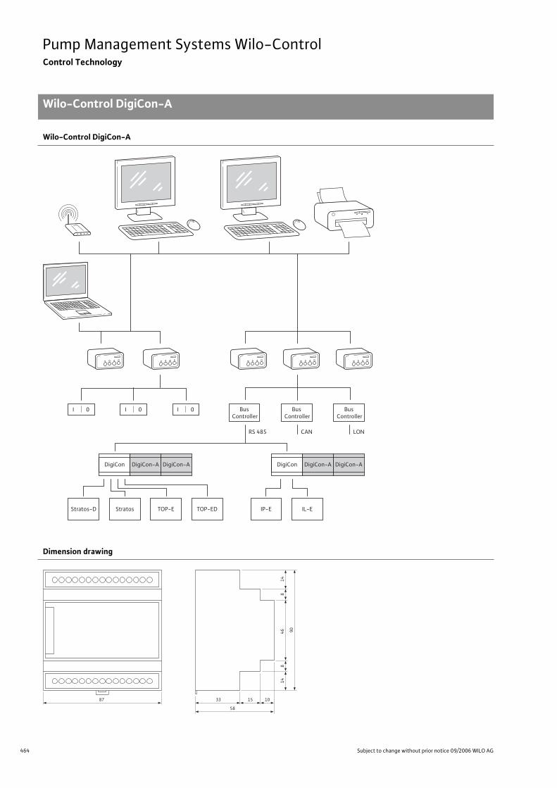
464 Subject to change without prior notice 09/2006 WILO AG
Pump Management Systems Wilo-ControlControl Technology
Wilo-Control DigiCon-A
Wilo-Control DigiCon-A
Dimension drawing
I 0 Bus
Controller
RS 485
Bus
Controller
CAN
Bus
Controller
DigiCon DigiCon-A DigiCon-A
Stratos-D Stratos
DigiCon DigiCon-A DigiCon-A
IP-E IL-ETOP-E TOP-ED
LON
I 0 I 0
14
46 90
87 33
58
15 10
14
88
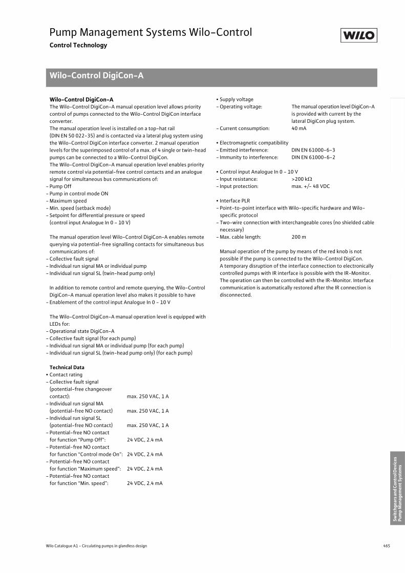
465
Pump Management Systems Wilo-ControlControl Technology
Wilo-Control DigiCon-A
Wilo Catalogue A1 - Circulating pumps in glandless design
Hea
tin
g, A
ir-c
on
dit
ion
ing
, C
oo
ling
Po
tab
le w
ater
cir
cula
tio
nSo
lar
ther
mal
Serv
ice/
Acc
esso
ries
, Sys
tem
sSw
itch
gear
s an
d C
ontr
ol D
evic
es
Pum
p M
anag
emen
t Sy
stem
s
Wilo-Control DigiCon-AThe Wilo-Control DigiCon-A manual operation level allows priority
control of pumps connected to the Wilo-Control DigiCon interface
converter.
The manual operation level is installed on a top-hat rail
(DIN EN 50 022-35) and is contacted via a lateral plug system using
the Wilo-Control DigiCon interface converter. 2 manual operation
levels for the superimposed control of a max. of 4 single or twin-head
pumps can be connected to a Wilo-Control DigiCon.
The Wilo-Control DigiCon-A manual operation level enables priority
remote control via potential-free control contacts and an analogue
signal for simultaneous bus communications of:
- Pump Off
- Pump in control mode ON
- Maximum speed
- Min. speed (setback mode)
- Setpoint for differential pressure or speed
(control input Analogue In 0 - 10 V)
The manual operation level Wilo-Control DigiCon-A enables remote
querying via potential-free signalling contacts for simultaneous bus
communications of:
- Collective fault signal
- Individual run signal MA or individual pump
- Individual run signal SL (twin-head pump only)
In addition to remote control and remote querying, the Wilo-Control
DigiCon-A manual operation level also makes it possible to have
- Enablement of the control input Analogue In 0 - 10 V
The Wilo-Control DigiCon-A manual operation level is equipped with
LEDs for:
- Operational state DigiCon-A
- Collective fault signal (for each pump)
- Individual run signal MA or individual pump (for each pump)
- Individual run signal SL (twin-head pump only) (for each pump)
Technical Data• Contact rating
- Collective fault signal
(potential-free changeover
contact): max. 250 VAC, 1 A
- Individual run signal MA
(potential-free NO contact) max. 250 VAC, 1 A
- Individual run signal SL
(potential-free NO contact) max. 250 VAC, 1 A
- Potential-free NO contact
for function “Pump Off”: 24 VDC, 2.4 mA
- Potential-free NO contact
for function “Control mode On”: 24 VDC, 2.4 mA
- Potential-free NO contact
for function “Maximum speed”: 24 VDC, 2.4 mA
- Potential-free NO contact
for function “Min. speed”: 24 VDC, 2.4 mA
• Supply voltage
- Operating voltage: The manual operation level DigiCon-A
is provided with current by the
lateral DigiCon plug system.
- Current consumption: 40 mA
• Electromagnetic compatibility
- Emitted interference: DIN EN 61000-6-3
- Immunity to interference: DIN EN 61000-6-2
• Control input Analogue In 0 - 10 V
- Input resistance: >200 k
- Input protection: max. +/- 48 VDC
• Interface PLR
- Point-to-point interface with Wilo-specific hardware and Wilo-
specific protocol
- Two-wire connection with interchangeable cores (no shielded cable
necessary)
- Max. cable length: 200 m
Manual operation of the pump by means of the red knob is not
possible if the pump is connected to the Wilo-Control DigiCon.
A temporary disruption of the interface connection to electronically
controlled pumps with IR interface is possible with the IR-Monitor.
The operation can then be controlled with the IR-Monitor. Interface
communication is automatically restored after the IR connection is
disconnected.
Pumpen Intelligenz.Worldwide the name Wilo is synonymous with the tradition of first class German engineering. Our pumps and pump systems for heating, air conditioning, cooling, water supply and sewage are used in all areas of public life: in commercial buildings, communal facilities, industry as well as in private homes. In close cooperation with our customers, we have over the decades further developed our know-how from pumps and beyond to system competence. This know-how is the basis for solutions which are geared towards meeting the special needs of our customers: that is what we call Pumpen Intelligenz.
WILO AGNortkirchenstraße 10044263 DortmundGermanyT +49 231 4102-0F +49 231 4102-7363www.wilo.com
Bosnia and Herzegovina71000 Sarajevo T +387 33 714510F +387 33 [email protected]
Georgia0177 TbilisiT/F +995 [email protected]
Macedonia1000 SkopjeT/ F +389 [email protected]
Moldova2012 ChisinauT/ F +373 2 [email protected]
TajikistanDushanbeT +992 93 5554541
Uzbekistan100046 TaschkentT/F +998 71 [email protected]
January 2007
Wilo – International (Subsidiaries)
Wilo – International (Representation offices)
AustriaWILO Handelsges. m.b.H.1230 WienT +43 5 07507-0F +43 5 [email protected]
AzerbaijanWILO Caspian LLC1014 BakuT +994 12 4992386F +994 12 [email protected]
BelarusWILO Bel OOO220035 MinskT +375 17 2503393F +375 17 [email protected]
BelgiumWILO SA/NV1083 GanshorenT +32 2 4823333F +32 2 [email protected]
BulgariaWILO Bulgaria Ltd.1125 Sofia T +359 2 9701970F +359 2 [email protected]
CanadaWILO Canada Inc. Calgary, Alberta T2A5L4T/F +1 403 [email protected]
ChinaWILO SALMSON (Beijing) Pumps System Ltd.101300 BeijingT +86 10 80493900F +86 10 [email protected]
CroatiaWILO Hrvatska d.o.o. 10090 ZagrebT +38 51 3430914F +38 51 [email protected]
Czech RepublicWILO Praha s.r.o.25101 CestliceT +420 234 098 711F +420 234 098 [email protected]
DenmarkWILO Danmark A/S2690 KarlslundeT +45 70 253312F +45 70 [email protected]
EstoniaWILO Eesti OÜ12618 TallinnT +372 6509780F +372 [email protected]
FinlandWILO Finland OY02330 EspooT +358 207401540F +358 [email protected]
FranceWILO S.A.S.78310 CoignièresT +33 1 30050930F +33 1 [email protected]
Great BritainWILO (U.K.) Ltd.DE14 2WJ Burton-Upon-TrentT +44 1283 523000F +44 1283 [email protected]
GreeceWILO Hellas AG14569 Anixi (Attika)T +302 10 6248300F +302 10 [email protected]
HungaryWILO Magyarország Kft2045 Törökbálint(Budapest)T +36 23 889500F +36 23 [email protected]
IrelandWILO Engineering Ltd.LimerickT +353 61 227566F +353 61 [email protected]
ItalyWILO Italia s.r.l.20068 PeschieraBorromeo (Milano)T +39 25538351F +39 [email protected]
KazakhstanWILO Central Asia 050002 AlmatyT +7 3272 785961F +7 3272 [email protected]
KoreaWILO Pumps Ltd. 621-807 GimhaeGyeongnarnT +82 55 3405809F +82 55 [email protected]
LatviaWILO Baltic SIA1019 RigaT +371 7 145229F +371 7 [email protected]
LebanonWILO SALMSON Lebanon12022030 El MetnT +961 4 722280F +961 4 [email protected]
LithuaniaWILO Lietuva UAB03202 VilniusT/F +370 2 [email protected]
MontenegroWILO Beograd d.o.o.11000 BeogradT +381 11 2850410F +381 11 [email protected]
The NetherlandsWILO Nederland b.v.1948 RC BeverwijkT +31 251 220844F +31 251 [email protected]
NorwayWILO Norge AS0901 OsloT +47 22 804570F +47 22 [email protected]
PolandWILO Polska Sp. z.o.o.05-090 RaszynT +48 22 7026161F +48 22 [email protected]
PortugalBombas Wilo-SalmsonPortugal Lda.4050-040 PortoT +351 22 2076900F +351 22 [email protected]
RomaniaWILO Romania s.r.l.041833 BucharestT +40 21 4600612F +40 21 [email protected]
RussiaWILO Rus ooo123592 MoscowT +7 495 7810690F +7 495 [email protected]
SerbiaWILO Beograd d.o.o.11000 BeogradT +381 11 2850410F +381 11 [email protected]
SlovakiaWILO Slovakia s.r.o.82008 Bratislava 28T +421 2 45520122F +421 2 [email protected]
SloveniaWILO Adriatic d.o.o.1000 LjubljanaT +386 1 5838130F +386 1 [email protected]
SpainWILO Ibérica S.A.28806 Alcalá de Henares(Madrid)T +34 91 8797100F +34 91 [email protected]
SwedenWILO Sverige AB35246 VäxjöT +46 470 727600F +46 470 [email protected]
SwitzerlandEMB Pumpen AG4310 RheinfeldenT +41 61 8368020F +41 61 [email protected]
TurkeyWILO Pompa Sistemleri San. ve Tic. A.S.34857 IstanbulT +90 216 6610203F +90 216 [email protected]
UkrainaWILO Ukraina t.o.w.01033 KiewT +38 044 2011870F +38 044 [email protected]
USAWILO-EMU LLCThomasville, Georgia31758-7810T +1 229 584 0098F +1 229 584 [email protected]
USAWILO USA LLC Calgary, Alberta T2A5L4T/F +1 403 [email protected]
Subject to change without prior notice. In appliance of our General Terms of Delivery and Service (see www.wilo.com)
W2695/6T/0609/GB/GMP