catalogue residential distribution
TRANSCRIPT

ResidentialDistribution
Catalogue
We’ve got a wide range of consumer unit configurations & devices to suit any application, from split load to advanced protection from arc faults & surges.

2

3
Changes to the wiring regulations with the release of the 18th Edition of BS 7671:2018 were published in July 2018 and came into effect on 1st January 2019.
These regulations had a significant impact on the design of residential electrical installations, which we expand upon in the following pages.
Residential Distribution solutions
Page
Overload Protection 4
RCD Selection 6
Surge Protection 8
Arc Fault Detection 10
Tailored Solutions 18
Catalogue Pages
Consumer Units 26
Protection Devices 34
Technical Pages 36
4
536.4.3.2"RCCBs & switches do not provide protection against overload, therefore they shall be protected by an overcurrent protective device."
536.4.202“ ... overload protection shall not solely be based on the use of diversity factors of the downstream circuits. To achieve overload protection of RCCBs or switches, the rated current of the overcurrent protective device (OCPD) shall be selected according to the manufacturers instructions”.
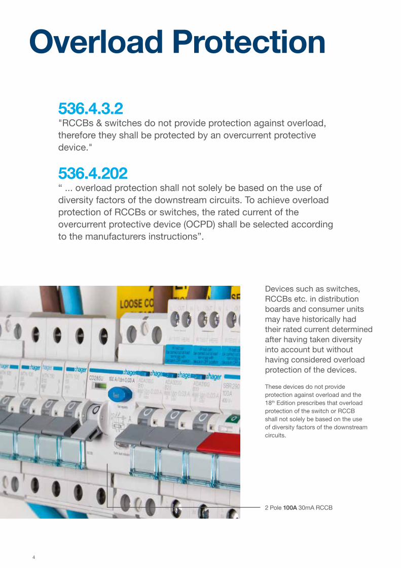
Devices such as switches, RCCBs etc. in distribution boards and consumer units may have historically had their rated current determined after having taken diversity into account but without having considered overload protection of the devices.
These devices do not provide protection against overload and the 18th Edition prescribes that overload protection of the switch or RCCB shall not solely be based on the use of diversity factors of the downstream circuits.
Overload Protection
2 Pole 100A 30mA RCCB

5
Overload protection of switches and RCCBs can be achieved by:
Method 1Ensure the sum of the rated current of the downstream MCBs do not exceed the rated current of the switch or RCCB (Inc). This method would however need to consider the consequences of any spare ways and later additions.
Method 2Ensure that the rated current of a switch or RCCB (Inc), stated by the assembly manufacturer, is not less than the rating of the upstream OCPD. For a domestic installation this could be a 100A cut-out fuse.
Method 3Select a consumer unit or distribution assembly that only utilises RCBOs on outgoing circuits. Consideration will still need to be given as to the rated current of the main switch.
Sw/D/I
MC
B
MC
B
MC
B
MC
B
MC
B
MC
B
MC
B
MC
B RCCBRCCBSp
are
Sp
are
Meter
005625.00
Service Cut-Out
RCCB 2 100A
RCCB 1 100A40A32A6A32A32A16A6A 6A 100A
86A 84A
Sw/D/I
MC
B
MC
B
MC
B
MC
B
MC
B RCCBRCCB Sp
are
Sp
are
Sp
are
Sp
are
Sp
are
Meter
005625.00
Service Cut-Out
RCCB 2 63A
RCCB 1 63A32A32A6A32A6A 63A
38A 70A
Example 1Maximum demand based upon diversity = 92 A (100% Largest load + 40% all other loads)Consumer Unit InA = 100A
Example 2Maximum demand based upon diversity = 62.4 A (100% Largest load + 40% all other loads)Consumer Unit InA = 63A
Method 1. Overload protection provided by:Sum of Rated current of downstream devices
RCCB1 ≥ Sum of rated current of downstream MCBs: 84 A RCCB2 ≥ Sum of rated current of downstream MCBs: 86 A
Method 2. Overload protection provided by:Upstream cut-out fuseRCCBs ≥ Rated current of upstream protectionRCCBs (100 A) - Cut-out fuse 100 A Cut-out fuse 80 A Cut-out fuse 60 A
Method 1. Overload protection provided by:Sum of Rated current of downstream devices
RCCB1 ≥ Sum of rated current of downstream MCBs: 70 A RCCB2 ≥ Sum of rated current of downstream MCBs: 38 A
Method 2. Overload protection provided by: Cut-out fuseRCCBs ≥ Rated current of upstream protectionRCCBs (63 A) - Cut-out fuse 100 A Cut-out fuse 80 A Cut-out fuse 60 A
Sw/D/I
RC
BO
RC
BO
RC
BO
RC
BO
RC
BO
RC
BO
RC
BO
RC
BOSp
are
Sp
are
Sp
are
Sp
are
Sp
are
Sp
are
Meter
005625.00
Service Cut-Out
32A32A32A32A 100A16A6A6A6A
Example 3 Maximum demand based upon diversity = 84 A (100% Largest load + 40% all other loads)Consumer Unit InA = 100A
Method 3. Overload protection provided by:Each RCBO
Method 2. Overload protection provided by:Upstream cut-out fuseSwitch ≥ Rated current of upstream protectionSwitch (100 A) - Cut-out fuse 100 A Cut-out fuse 80 A Cut-out fuse 60 A
Note: Potential future loads on spare ways should be considered.
SummaryA consumer unit with a rated current of 100A (InA), with two RCCB 100A (Inc) will allow the consumer unit to be installed in any single phase application up to 100A.

6
RCDs exist in various different forms and react differently depending on the presence of DC components or different frequencies. The following RCDs are available with the respective symbols and the designer or installer is required to select the appropriate device for the specific application:
RCD Selection
Type AC General purpose use
RCD can detect & respond to AC sinusoidal wave only.
Type AEquipment incorporating electronic components
RCD can detect & respond the same as Type AC+ pulsating DC components.
Type FEquipment with frequency controlled speed drives
RCD can detect & respond the same as Type A + high frequency residual current.
Type BElectric vehicle chargers, PV supplies
RCD can detect & respond the same as Type F + smooth DC residual current.

7
RCD Examples of type of equipment / load
Type AC
Resistive, Capacitive, Inductive loads generally without any electronic components, typically:
• Immersion heater• Oven/Hob with resistive heating elements (no electronic clock/timer etc.)• Electric shower (no electronic display)• Tungsten & halogen lighting (no LED lamps and drivers)
Type A
Single phase with electronic components, typically:
• Single phase invertors• Class 1 IT and Multimedia equipment• Power supplies for Class 2 equipment• Appliances such as a washing machine that is not frequency controlled e.g. d.c. or
universal motor• Lighting controls such as a dimmer switch and home and building electronic
systems LED drivers• Induction hobs• Electric vehicle (EV) charging where any smooth DC fault current is less than 6 mA
Type A is also suitable for Type AC applications.
Type F
Frequency controlled equipment / appliances, typically:
• Some washing machines, dishwashers and dryers e.g. containing synchronous motors*
• Some class 1 power tools• Some air conditioning controllers using variable frequency speed drives
Type F is also suitable for Type AC and Type A applications.
Type B
Three phase electronic equipment typically:
• Inverters for speed control• UPS• Electric Vehicle charging where any smooth DC fault current is greater than 6mA• Photo voltaic• Power Electronic Converter Systems (PECS) typically:• Industrial machines• Cranes
Type B is also suitable for Type AC, Type A and Type F applications.
Note: Table taken from BEAMA guide to the selection and application of residual current devices (RCDs).
SummaryFor split load consumer units, Type A RCDs are advised as it is unlikely that any group of circuits will not require at least Type A protection.

8
Surge Protection
Transient Overvoltages
Products such as computers, printers, flat screen televisions, alarms, microwaves and washing machines are common place. These can all be vulnerable to transient overvoltages, which can significantly reduce the equipment’s lifespan through degradation and damage.
A transient overvoltage or surge is a short duration increase in voltage measured between two or more conductors. In short, this means anything from microseconds (millionths of a second) to a few milliseconds (thousandths of a second) in duration.
With everyday activities relying on electronic equipment, the whole nature of how electrical equipment is used in homes and at work has evolved.
443.4
Protection against overvoltages shall be provided where the consequence caused by overvoltage could:
(i) Result in serious injury to, or loss of, human life, or(ii) Result in the interruption of public services and/or damage to cultural heritage, or(iii) Result in interruption of commercial or industrial activity, or(iv) Affect a large number of co-located individuals.
For all other cases, a risk assessment according to regulation 443.5 shall be performed to determine if protection against transient overvoltage is required. If the risk assessment is not performed, the electrical installation shall be provided with protection against transient overvoltages, except for single dwelling units where the total value of the installation and equipment therein does not justify such protection.
443.5
Calculated risk level (CRL) is used to determine if protection against overvoltages of atmospheric origin is required. The CRL is found by the following formula:
CRL = fenv/(LpxNg)
WhereFenv is an environmental factor selected according to Table 443.1 (Rural/Suburban or Urban)Lp is the risk assessment length in kmNg is the lightning ground flash density (flashes per km² per year) relevant to the location of the power line and connected structure (see figure 44.2).
If the CRL value is less than 1000 then SPD protection shall be installed. If the CRL value is 1000 or higher then SPD protection is not required for the installation.
SummaryIt is unlikely that the value of an installation and the equipment therein will not justify the cost of surge protection. Hence, the risk assessment method will be the determining factor as to when surge protection is required. If the location is rural/suburban and the length of cable is unknown and the lightning flash density is at its lowest then the calculation will look like this;
CRL = fenv/(LpxNg)CRL = 85/1x0.1CRL = 850
Which means that surge protection will be required.

9
Surge Protection Devices
SPD’s protect electrical and electronic equipment against transients, originating from lightning, switching of transformers, lighting and motors. These transients can cause premature aging of equipment, downtime, or complete destruction of electronic components and materials. SPDs are strongly recommended for installations that are exposed to transients, to protect sensitive and expensive electrical equipment such as TVs, washing machines, PCs, alarms etc.
Selection Criteria
Iimp – Impulse current of 10/350 μs waveform associated with Type 1 SPD’s.
In – Surge current of 8/20 μs waveform associated with Type 2 SPD’s.
Up - The residual voltage that is measured across the terminal of the SPD when In is applied.
Uc - The maximum voltage which may be continuously applied to the SPD without it conducting.
Terminology
Surge protection devices are classified according to their functions:
Type 1SPD which can discharge partial lightning current with a typical waveform 10/350 μs. Usually employs spark gap technology.
Type 2SPD which can prevent the spread of overvoltages in the electrical installations and protects equipment connected to it. It usually employs metal oxide varistor (MOV) technology and is characterised by an 8/20 μs current wave.
Type 3These SPDs have a low discharge capacity. They must therefore only be installed as a supplement to Type 2 SPD and in the vicinity of sensitive loads. Type 3 SPD’s are characterised by a combination of voltage waves (1.2/50 μs) and current waves (8/20 μs).

10
Arc Fault DetectionDevices
Arc fault detection devices (AFDD) use microprocessors to identify characteristic current flow and voltage curves that indicate an arc fault and automatically trip the affected circuit.
This significantly reduces the risk of fire due to faulty conductors and connections. The protective function of the AFDD has already proven its worth internationally and the use of arc fault detection devices conforming to BS EN 62606 is recommended as a means of providing additional protection in AC final circuits.
The 18th Edition of BS 7671, recommends the use of these to provide additional protection against fire.
Potential CausesArc faults can be caused by all types of line faults and worn contacts. An AFDD will trip the circuit when a potentially hazardous arc occurs, eliminating the resulting fire hazard.
Series Arc FaultParallel Arc Fault
Kink/break in the cable Cable wear due to frequent use
Line damage resulting from drilling or construction work
Incorrect wire stripping
Incorrect bending radii Loose screwed connections
Defective plugs Rodent bites
11
AFDD
Monitoring via Microprocessor
An AFDD is activated by both series and parallel arc faults. Unlike circuit breakers or RCDs, an AFDD does not have an electromechanical trigger, but utilises electronic technology to analyse the signature (waveform) of an arc. It reliably differentiates between an arc fault and the signature (waveform) in normal switching and control events, preventing false tripping.
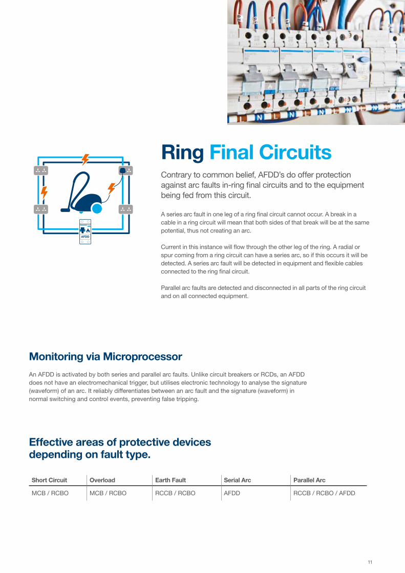
Ring Final CircuitsContrary to common belief, AFDD’s do offer protection against arc faults in-ring final circuits and to the equipment being fed from this circuit. A series arc fault in one leg of a ring final circuit cannot occur. A break in a cable in a ring circuit will mean that both sides of that break will be at the same potential, thus not creating an arc. Current in this instance will flow through the other leg of the ring. A radial or spur coming from a ring circuit can have a series arc, so if this occurs it will be detected. A series arc fault will be detected in equipment and flexible cables connected to the ring final circuit. Parallel arc faults are detected and disconnected in all parts of the ring circuit and on all connected equipment.
Effective areas of protective devices depending on fault type.
Short Circuit Overload Earth Fault Serial Arc Parallel Arc
MCB / RCBO MCB / RCBO RCCB / RCBO AFDD RCCB / RCBO / AFDD

12
Design 10
Design 30
Design 50 focuses on clean aesthetics and a flush fit for seamless integration into any home. Design 50 comes with all the installation features you would expect from us, such as an incoming cable clamp and cable protector plate, as well as a series of colour options, finishes & sizes. There’s a Design 50 for any home environment.
Design 30 is our enhanced consumer unit, created to be more aesthetically pleasing whilst including extra features to ease installation. Design 30 comes with a cable clamp installed and rear cable entry plate supplied, which allows for incoming meter tails to be safely secured, eliminating stresses within the switch terminal.
Residential DistributionConsumer Units
Design 50
Design 10 is our board for all applications. As with all models in the range, there is ample cable space available even when RCBOs are fitted. The top mounted terminal rail makes the wiring of the neutral and earth connections neat and simple. Multiple fixing points are available to ease installation and a full metal DIN rail ensure the devices sit square. Available in surface and flush.

13
RCBOs
RCDs exist in various different forms and react differently depending on the presence of DC components or different frequencies. We offer most RCBOs for residential applications in a reduced height form, giving more space for cabling during installation.
Arc fault protection devices (AFDD) use microprocessors to identify characteristic current flow and voltage curves that indicate an arc fault and automatically trip the affected circuit.
This significantly reduces the risk of fire due to faulty conductors and connections.
SPD’s protect electrical and electronic equipment against transients, originating from lightning, switching of transformers, lighting and motors. These transients can cause premature aging of equipment, downtime, or complete destruction of electronic components and materials.
SPDs are strongly recommended for installations that are exposed to transients, to protect sensitive and expensive electrical equipment such as TVs, washing machines, PCs, alarms etc.
Residential DistributionConsumer Units Additional Protection
Surge Protection
Arc Fault Detection

14
01 From 2 to 40 Ways
With the ability to accommodate from 2 to 40 outgoing ways, there is a solution for an incredible range of requirements from a high number of protected circuits, either MCB or RCBO, to the installation of surge protection or building automation.
Design 30Surface & Dual RowDesign 30 was created with improved aesthetics and features for applications where the board would be installed in visible locations within a home. Dual row boards have been designed to accommodate large numbers of outgoing circuits & facilitate installation where horizontal space can be limited.

15
02 Locate & Hold Cover
Multiple tabs along the top of the cover locate with slots in the base to hold the cover in place during installation, leaving both hands free to fix the cover to the base.
05 Cable Entry Protector Plates
Cable protector plates are used to ensure that cables can enter the consumer unit without damage from sharp edges created by the removal of knockouts. We provide solutions for meter tail entry, top wall entry of outgoing circuits and rear cable entries. Additional cable protector plates are available as accessories.
04 Lockable
Our health & safety lock assembly provides the ability to isolate circuits and secure the consumer unit prior to occupation of a property. This is achieved with the use of the health & safety bracket (VMHBL) and padlock (JK25A). When the lock is removed, the cover can be clicked back into place, restoring the board to its original state.
03 Cable Clamp
Incoming meter tails can be safely secured with a single screw, preventing stresses caused by movement of the meter tails outside the consumer unit from being transmitted to the terminals of the main switch.

16
01 Options
We offer flush boards in both Design 10 and Design 50 covers. Both boards have all the same installation features. Design 50 comes as standard in white, but with the option of having a bespoke finish of any RAL colour, or even a custom design can be vinyl wrappedonto the board to provide a truly individual unit for every home.
Design 10 & 50FlushFor applications where flush fitting a board is desired, we offer two options.
We’ve put extra consideration into how these boards are typically installed and included features to make the job of installing them as easy and quick as possible.

17
02 Removable Frame
The frame contains the incomer, neutral and earth terminals and the cable clamp. This can be removed whilst the building work is completed and quickly re-installed into the back-box later. It is then secured with the use of four wing nuts, removing the need for any special tools.
03 Installation Depth
To allow for a range of installation depths within a wall, the frame is adjustable. There are flanges on the frame which sit on the finished surface of the wall, helping to ensure that the devices always protrude through the front cover uniformly and that the cover fits flat to the wall, ensuring that the finished installation looks the part.
04 Cable Clamp
A cable clamp comes as standard on all of our flush fit boards to help prevent any movement of meter tails being transmitted to the terminals of the main switch and to secure the tails in place inside the board.
05 Back Box Installation
Knockouts on the top, bottom, sides and rear of the back box allow for multiple cable entry options. Oval knockouts can be protected with 38mm open grommet (VMGROM).Raised sides on the back box give a reference for plasterboarding with multiple fixing points throughout to ensure a secure installation.

18
Tailored SolutionsFrom fitting devices through to bespoke engineering, Tailored Solutions provides a complete service for any project.
For your project we can offer a solution which can meet the most demanding of challenges. From design & engineering through to logistics, our Tailored Solutions service offers unrivalled support & peace of mind for you and your business.
Design & engineering input at the pre-order stage
Factory tested and assembled before despatch
Technical support throughout the project life-cycle
Delivery and call off schedules Site specific logistics
Our teams will design and engineer a bespoke solution at an early stage for your project. The teamwork approach ensures that we can accommodate even the most demanding requirement.
We will deliver the solution to you exactly when you need it, directly to site, all at once or piece by piece. We tailor our delivery to suit your needs.
For even the most demanding of sites, with specific delivery time slots and access restrictions, our team will make sure the solution is on site when and where you need it.
Interested in Tailored Solutions?
Telephone: 01952 675 689Online form: go.hager.com/tailored
Our dedicated Tailored Solutions team are all based on the same site, and are on hand throughout the life-cycle of the project, with expert knowledge and understanding of your requirements.
Our rigorous factory testing ensures any tailored solution is fully compliant to the latest regulations and your specification, ensuring minimised risk and total confidence on product performance.

19

2020
ResidentialDistributionFunctional, stylish, and innovative, our Design Range of consumer units provide an exceptional option for any home. In addition, we offer MCB’s and RCBO’s as well as new surge protection and arc fault detection solutions to provide optimal protection.

21
Res
iden
tial
Dis
trib
utio
n
04 Page
Consumer Units
Surface Mounted Consumer Units
Design 10 22
Design 30 26
Flush Mounted Consumer Units
Design 10 30
Design 50 31
Consumer Unit Accessories 32
Protection Devices
MCBs 34
RCCBs 34
RCBOs 35
Arc Fault Detection Devices 35
Surge Protection 35
Technical Pages 36

22 Data is subject to errors and technical modifications. New.
Res
iden
tial
Dis
trib
utio
nSurface Mounted Consumer UnitsDesign 10
Switch Disconnector Incomer
RCCB Incomer
Characteristics: - All Design 10 consumer units contain top, bottom & rear knockouts and a meter tail cable entry plate (VM04CE) as standard- see page 36 for knockout sizes.
- Supplied with a full metal DIN rail, 100A switch disconnector incomer and a full complement of earth and neutral terminals along with marking labels, busbar and instructions.
- References ending in SPD come with a Type 2 SPD fitted. - Recommended for use with TT systems when utilising RCBO on all outgoing circuits. - We also recommend the use of cable clamp (VA10MT) for use on TT systems, available as an accessory. - Conforms to BS EN 61439-3 Including Annex ZB (16kA rating). - For accessories see page 32, for dimensions see page 36, refer to board sizes below.
Characteristics: - All Design 10 consumer units contain top, bottom & rear knockouts and a meter tail cable entry plate (VM04CE) as standard- see page 36 for knockout sizes.
- Supplied with a full metal DIN rail, 40A, 63A or 100A 30mA Type A RCCB incomer and a full complement of earth and neutral terminals along with marking labels, busbar and instructions.
- Conforms to BS EN 61439-3 Including Annex ZB (16kA rating). - For accessories see page 32, for dimensions see page 36, refer to board sizes below.
VML106
VML310AH
Sw/D/I
Description Size Cat ref.Cat ref.With Round Knockouts
2 Way 63A Switch Disconnector Incomer 2 VML202 VML202RK
6 Way 63A Switch Disconnector Incomer 3 VML206 VML206RK
6 Way 100A Switch Disconnector Incomer 3 VML106 VML106RK
10 Way 100A Switch Disconnector Incomer 4 VML110 VML110RK
14 Way 100A Switch Disconnector Incomer 5 VML114 VML114RK
20 Way 100A Switch Disconnector Incomer 7 VML120 VML120RK
8 Way 100A Switch Disconnector Incomer with Factory Fitted Surge Protection
4 VML108SPD VML108SPDRK
12 Way 100A Switch Disconnector Incomer with Factory Fitted Surge Protection
5 VML112SPD VML112SPDRK
18 Way 100A Switch Disconnector Incomer with Factory Fitted Surge Protection
7 VML118SPD VML118SPDRK
6 + 6 Way Dual Row 100A Switch Disconnector Incomer 3 (2) VML10606 -
10 + 10 Way Dual Row 100A Switch Disconnector Incomer 4 (2) VML11010 -
14 + 14 Way Dual Row 100A Switch Disconnector Incomer 5 (2) VML11414 -
20 + 20 Way Dual Row 100A Switch Disconnector Incomer 7 (2) VML12020 -
8 + 10 Way Dual Row 100A Switch Disconnector Incomer with Factory Fitted Surge Protection
4(2) VML10810SPD -
12 + 14 Way Dual Row 100A Switch Disconnector Incomer with Factory Fitted Surge Protection
5(2) VML11214SPD -
18 + 20 Way Dual Row 100A Switch Disconnector Incomer with Factory Fitted Surge Protection
7(2) VML11820SPD -
Description Size Cat ref.Cat ref.With Round Knockouts
2 Way 63A 30mA Type A RCCB Incomer 2 VML402AH -
6 Way 63A 30mA Type A RCCB Incomer 3 VML406AH -
10 Way 63A 30mA Type A RCCB Incomer 4 VML410AH -
6 Way 100A 30mA Type A RCCB Incomer 3 VML306AH VML306AHRK
10 Way 100A 30mA Type A RCCB Incomer 4 VML310AH VML310AHRK
14 Way 100A 30mA Type A RCCB Incomer 5 VML314AH VML314AHRK
Sw/D/I
Dual Row
RCCB
SPDSw/D/I
Sw/D/I SPD
with Surge
Dual Rowwith Surge
23Data is subject to errors and technical modifications. New.
Res
iden
tial
Dis
trib
utio
n
Surface Mounted Consumer UnitsDesign 10
Split Load
Characteristics: - All Design 10 consumer units contain top, bottom & rear knockouts and a meter tail cable entry plate (VM04CE) as standard- see page 36 for knockout sizes.
- Supplied with 2 x Type A RCCBs, a full metal DIN rail, 100A switch disconnector incomer and a full complement of earth and neutral terminals along with marking labels, busbar and instructions.
- Conforms to BS EN 61439-3 Including Annex ZB (16kA rating). - * 100A device in these boards are de-rated to 80A. - For accessories see page 32, for dimensions see page 36.
VM966H
Description Size Cat ref.Cat ref. With Round Knockouts
6 Way 3+3 80A Switch 2x 80A 30mA RCCB* 4 VML933H* VML933RK*
10 Way 5+5 100A Switch 2x 100A 30mA RCCB 5 VML955H VML955RK
12 Way 6+6 100A Switch 2x 100A 30mA RCCB 6 VML966H VML966RK
14 Way 6+6+2 100A Switch 3x 100A 30mA RCCB 7 VML9662 -
4 + 6 Way Dual Row 100A Switch 2x 100A 30mA RCCB 3(2) VML946H -
8 + 10 Way Dual Row 100A Switch 2x 100A 30mA RCCB 4(2) VML90810H -
12 + 14 Way Dual Row 100A Switch 2x 100A 30mA RCCB 5(2) VML91214H -
18 + 20 Way Dual Row 100A Switch 2x 100A 30mA RCCB 7(2) VML91820H -
RCCBRCCB Sw/D/I
RCCB
RCCB
Sw/D/I
Dual Row
Configurable High Integrity
Characteristics: - Metal split load and configurable consumer units with the ability to protect selected circuits with RCBOs/MCBs and the remainder of circuits split across two RCCBs.
- All Design 10 consumer units contain top, bottom & rear knockouts and a meter tail cable entry plate (VM04CE) as standard- see page 36 for knockout sizes.
- Supplied with 2 x Type A RCCBs, a full metal DIN rail, 100A switch disconnector incomer and a full complement of earth and neutral terminals along with marking labels, busbar and instructions.
- References ending in SPD come with a Type 2 SPD fitted. - Conforms to BS EN 61439-3 Including Annex ZB (16kA rating). - For accessories see page 32, for dimensions see page 36.
VML912C
Description Size Cat ref.Cat ref. With Round Knockouts
10 Way 100A Switch 2x 100A 30mA RCCB 5 VML910C -
12 Way 100A Switch 2x 100A 30mA RCCB 6 VML912C -
16 Way 100A Switch 2x 100A 30mA RCCB 7 VML916C -
10 Way High Integrity 100A Switch 2x 100A 30mA RCCB 5 VML910CU VML910CURK
12 Way High Integrity 100A Switch 2x 100A 30mA RCCB 6 VML912CU -
16 Way High Integrity 100A Switch 2x 100A 30mA RCCB 7 VML916CU VML916CURK
8 Way High Integrity 100A Switch 2x 100A 30mA RCCB with Factory Fitted Surge Protection
5 VML908CUSPD VML908CUSPDRK
10 Way High Integrity 100A Switch 2x 100A 30mA with Factory Fitted Surge Protection
6 VML910CUSPD VML910CUSPDRK
14 Way High Integrity 100A Switch 2x 100A 30mA RCCB with Factory Fitted Surge Protection
7 VML914CUSPD VML914CUSPDRK
8+10 Way Dual Row High Integrity 100A Switch 2x 100A 4(2) VML90810CU -
12+14 Way Dual Row High Integrity 100A Switch 2x 100A 5(2) VML91214CU -
18+20 Way Dual Row High Integrity 100A Switch 2x 100A 7(2) VML91820CU -
6+10 Way Dual Row High Integrity 100A Switch 2x 100A 30mA RCCB with Factory Fitted Surge Protection
4(2) VML90610CUSPD -
10+14 Way Dual Row High Integrity 100A Switch 2x 100A 30mA Type RCCB with Factory Fitted Surge Protection
5(2) VML91014CUSPD -
16+20 Way Dual Row High Integrity 100A Switch 2x 100A 30mA RCCB with Factory Fitted Surge Protection
7(2) VML91620CUSPD -
12 Way Configurable, 100A Switch 1x 100A 30mA RCCB (Remaining Ways for RCBOs)
5 VML512AC -
18 Way Configurable, 100A Switch 1x 100A 30mA RCCB (Remaining Ways for RCBOs)
7 VML518AC -
RCCB RCCB Sw/D/I
RCCB
RCCB Sw/D/I
Dual Row
with Surge
Dual Rowwith Surge
RCCB
RCCB Sw/D/I SPD
RCCBRCCB Sw/D/I SPD
24 Data is subject to errors and technical modifications. New.
Res
iden
tial
Dis
trib
utio
nSurface Mounted Consumer UnitDesign 10
Garage Boards
Characteristics: - Consumer unit comes complete with Type A RCCB, 40A 30mA RCCB Incomer, 32A MCB and 6A MCB, earth & neutral connections, busbar, grommet strip, marking labels & Instructions.
- All Design 10 consumer units contain top, bottom & rear knockouts and a meter tail cable entry plate (VM04CE) as standard- see page 36 for knockout sizes.
- Cable protector plate for rear knockouts is available as an accessory. (VM02CE) - Conforms to BS EN 61439-3 - For dimensions see page 36.
VML24AH Description Size Cat ref.
2 Way 40A 30mA Type A RCCB with 1x 32A & 1x 6A MCB 2 VML24AH
RCCB
MC
B
MC
B
Multi Tariff
Characteristics: - All Design 10 consumer units contain top, bottom & rear knockouts and a meter tail cable entry plate (VM04CE) as standard- see page 36 for knockout sizes.
- Supplied with Type A RCCBs, a full metal DIN rail, multiple switch disconnector incomers and a full complement of earth and neutral terminals along with marking labels, busbar and instructions.
- Conforms to BS EN 61439-3 Including Annex ZB (16kA rating). - For accessories see page 32, for dimensions see page 36.VML918C
Description Size Cat ref.
18 Way Twin Tariff Configurable 2x 100A Switch 7 VML918C
12 Way Multi Tariff 6+5+1 2x100A 1x 63A Switch 6 VML9651
10 Way Split Load 5+5 100A Switch 2x 100A Type A RCCB1x 100A Type A RCCB Incomer 14 Ways Dual Row
5 (2) VML955914H
Sw/D/ISw/D/I
Sw/D/ISw/D/ISw/D/I
63 100 100
Sw/D/I
63 100 100
RCCB
RCCBRCCB
Dual Row
Time Delayed RCCB Incomer
Characteristics: - All Design 10 consumer units contain top, bottom & rear knockouts and a meter tail cable entry plate (VM04CE) as standard- see page 36 for knockout sizes.
- Supplied with Type A RCCBs, a full metal DIN rail 100A 100mA time delayed incomer and a full complement of earth and neutral terminals along with marking labels, busbar, meter tail clamp and instructions.
- Recommended for use with TT systems (meter tail clamp secures meter tails to prevent accidental disconnection and contact with metal enclosure).
- References ending in SPD come with a Type 2 SPD fitted. - Conforms to BS EN 61439-3 Including Annex ZB (16kA rating). - For accessories see page 32, for dimensions see page 36, refer to board sizes below.
VML912TG
Description Size Cat ref.
12 Way Configurable 100A 100mA Time Delay Type A RCCB 100A 30mA Type A RCCB 5 VML912TG
12 Way 100A 100mA Time Delay Type A RCCB 2x 100A 30mA Type A RCCB 6 VML966TG
10 Way 100A 100mA Time Delayed + 2 x 100A RCCB with Factory Fitted Surge Protection
6 VML955TGSPD
10 Way Configurable 100A 100mA Time Delayed RCCB +100A 30mA with Factory Fitted Surge Protection
5 VML910TGSPD
RCCB RCCB30mA
100mA
RCCB RCCBRCCB
RCCB RCCBRCCB SPD
RCCB RCCB30mA
100mA
SPD
with Surge
with Surge
25Data is subject to errors and technical modifications. New.
Res
iden
tial
Dis
trib
utio
n
Surface Mounted Consumer UnitsDesign 10
Arc Fault Protection
Characteristics: - Metal split load board with 100A incomer and 2 x 100A RCCBs. - Supplied with Type A RCCBs - Supplied with double pole busbar system. - All Design 10 consumer units contain top, bottom & rear knockouts and a meter tail cable entry plate (VM04CE) as standard- see page 36 for knockout sizes.
- Supplied with Type A RCCBs, a full metal DIN rail, switch disconnector incomer and a full complement of earth and neutral terminals along with marking labels, busbar and instructions.
- Conforms to BS EN 61439-3, Annex ZB (16kA Rating) - Suitable for use with Hager 2 pole Arc Fault Detection Devices ARC*** - For accessories see page 32, for dimensions see page 36, refer to board sizes below.
Description Size Cat ref.
5 + 4 Way Dual Row, 100A Switch Disconnector 2x 100A 30mA RCCB, 2 Pole Busbar,for Arc Fault Detection devices
4(2) VMLA90405H
6 + 7 Way Dual Row, 100A Switch Disconnector 2x 100A 30mA RCCB, 2 Pole Busbar, for Arc Fault Detection devices
5(2) VMLA90607H
9 + 10 Way Dual Row, 100A Switch Disconnector 2x 100A 30mA RCCB, 2 Pole Busbar, for Arc Fault Detection devices
7(2) VMLA90910H
5 + 7 Way Dual Row, 100A Switch Disconnector 2x 100A 30mA RCCB, 2 Pole Busbar,+ Surge Protection Devices, for Arc Fault Detection Devices
5(2) VMLA90507HSPD
8 + 10 Way Dual Row, 100A Switch Disconnector 2x 100A 30mA RCCB, 2 Pole Busbar,+ Surge Protection Devices, for Arc Fault Detection Devices
7(2) VMLA90810HSPD
VMLA90405H
RCCB
RCCBAFDDAFDD
AFDDAFDDAFDD Sw/D/I
Tailored SolutionsWe can provide the right solution that meets your specification. If your enquiry falls out of the standard offer, for example if you require AFDD in combination with MCBs, RCCBs or RCBOs, Tailored Solutions can meet your requirements.
For more information on this service, see page 18.
Arc Fault Detection Devices
Characteristics: - Protection device which combines an MCB with an Arc Fault Detection Device. - Complies with BS EN 62606 - Current rating 6A - 40A 6kA - Available in B & C curve - Connection capacity - Rigid=25mm², Flexible = 16mm²
ARC906U
DescriptionWidth (1 Mod =17.5mm)
Cat ref.B Curve
Cat ref. C Curve
6A 2 Mod ARC906U ARC956U
10A 2 Mod ARC910U ARC960U
16A 2 Mod ARC916U ARC966U
20A 2 Mod ARC920U ARC970U
25A 2 Mod ARC925U ARC975U
32A 2 Mod ARC932U ARC982U
40A 2 Mod ARC940U ARC990U
Interested in Tailored Solutions?
Telephone: 01952 675 689Online form: go.hager.com/tailored

26 Data is subject to errors and technical modifications. New.
Res
iden
tial
Dis
trib
utio
nSurface Mounted Consumer UnitsDesign 30
Switch Disconnector Incomer
RCCB Incomer
Characteristics: - All consumer units contain rear cable entry. Boards with knockouts have top & bottom knockouts. A meter tail cable entry plate (VM04CE) is provided as standard - see page 36 for knockout sizes.
- Supplied with a full metal DIN rail, 100A switch disconnector incomer and a full complement of earth and neutral terminals along with marking labels, busbar, instructions, rear cable protector plate and meter tail clamp.
- References ending in SPD come with a Type 2 SPD fitted. - Recommended for use with TT systems when utilising RCBOs on outgoing circuits. - Conforms to BS EN 61439-3 Including Annex ZB (16kA rating). - For accessories see page 32, for dimensions see page 36, refer to board sizes below.
Characteristics: - All consumer units contain rear cable entry. Boards with knockouts have top & bottom knockouts. A meter tail cable entry plate (VM04CE) is provided as standard - see page 36 for knockout sizes.
- Supplied with a full metal DIN rail, 40A, 63A or 100A 30mA Type A RCCB incomer and a full complement of earth and neutral terminals along with marking labels, busbar, instructions, rear cable protector plate and meter tail clamp.
- Conforms to BS EN 61439-3 Including Annex ZB (16kA rating). - For accessories see page 32, for dimensions see page 36, refer to board sizes below.
Description Size Cat ref.Cat ref.With Knockouts
2 Way 63A Switch Disconnector Incomer 2 VM202 VM202K
6 Way 63A Switch Disconnector Incomer 3 VM206 VM206K
6 Way 100A Switch Disconnector Incomer 3 VM106 VM106K
10 Way 100A Switch Disconnector Incomer 4 VM110 VM110K
14 Way 100A Switch Disconnector Incomer 5 VM114 VM114K
20 Way 100A Switch Disconnector Incomer 7 VM120 VM120K
8 Way 100A Switch Disconnector Incomer with Factory Fitted Surge Protection
4 VM108SPD VM108KSPD
12 Way 100A Switch Disconnector Incomer with Factory Fitted Surge Protection
5 VM112SPD VM112KSPD
18 Way 100A Switch Disconnector Incomer with Factory Fitted Surge Protection
7 VM118SPD VM118KSPD
6+6 Way Dual Row 100A Switch Disconnector Incomer 3 (2) VM10606 VM10606K
10+10 Way Dual Row 100A Switch Disconnector Incomer 4 (2) VM11010 VM11010K
14+14 Way Dual Row 100A Switch Disconnector Incomer 5 (2) VM11414 VM11414K
20+20 Way Dual Row 100A Switch Disconnector Incomer 7 (2) VM12020 VM12020K
8 + 10 Way Dual Row 100A Switch Disconnector Incomer with Factory Fitted Surge Protection
4(2) VM10810SPD VM10810KSPD
12 + 14 Way Dual Row 100A Switch Disconnector Incomer with Factory Fitted Surge Protection
5(2) VM11214SPD VM11214KSPD
18 + 20 Way Dual Row 100A Switch Disconnector Incomer with Factory Fitted Surge Protection
7(2) VM11820SPD VM11820KSPD
Description Size Cat ref.Cat ref.With Knockouts
6 Way 100A 30mA Type A RCCB Incomer 3 VM306AH VM306AHK
10 Way 100A 30mA Type A RCCB Incomer 4 VM310AH VM310AHK
14 Way 100A 30mA Type A RCCB Incomer 5 VM314AH VM314AHK
2 Way 40A 30mA Type A RCCB Incomer 2 VM402AH VM402AHK
6 Way 63A 30mA Type A RCCB Incomer 3 VM406AH VM406AHK
10 Way 63A 30mA Type A RCCB Incomer 4 VM410AH VM410AHK
VM106
VM410AH
Sw/D/I
RCCB
Sw/D/I
Dual Row
SPDSw/D/I
Sw/D/I SPD
with Surge
Dual Rowwith Surge

27Data is subject to errors and technical modifications. New.
Res
iden
tial
Dis
trib
utio
n
RCCB
RCCB
Sw/D/I
Surface Mounted Consumer UnitsDesign 30
Split Load
Characteristics: - All consumer units contain rear cable entry. Boards with knockouts have top & bottom knockouts. A meter tail cable entry plate (VM04CE) is provided as standard - see page 36 for knockout sizes.
- Supplied with Type A RCCBs, a full metal DIN rail, 100A switch disconnector incomer, 2 100A RCCBs and a full complement of earth and neutral terminals along with marking labels, busbar, instructions, rear cable protector plate and meter tail clamp.
- Conforms to BS EN 61439-3 Including Annex ZB (16kA rating). - For accessories see page 32, for dimensions see page 36, refer to board sizes below.
Description Size Cat ref.Cat ref.With Knockouts
10 Way Split Load 5+5 100A Switch 2x 100A 30mA RCCB 5 VM955H VM955HK
12 Way Split Load 6+6 100A Switch 2x 100A 30mA RCCB 6 VM966H VM966HK
4+6 Way Dual Row 100A Switch 2x 100A 30mA RCCB 3 (2) VM946H VM946HK
8+10 Way Dual Row 100A Switch 2x 100A 30mA RCCB 4 (2) VM90810H VM90810HK
12+14 Way Dual Row 100A Switch 2x 100A 30mA RCCB 5 (2) VM91214H VM91214HK
18+20 Way Dual Row 100A Switch 2x 100A 30mA RCCB 7 (2) VM91820H VM91820HK
VM955H
RCCBRCCB Sw/D/I
Dual Row
RCCB
RCCB Sw/D/I
Configurable High Integrity
Characteristics: - Metal split load and configurable consumer units with ability to protect selected circuits with RCBOs/MCBs and the remainder of circuits split across two RCCBs.
- All consumer units contain rear cable entry. Boards with knockouts have top & bottom knockouts. A meter tail cable entry plate (VM04CE) is provided as standard - see page 36 for knockout sizes.
- Supplied with Type A RCCBs, a full metal DIN rail, 100A switch disconnector incomer, 2 100A RCCBs and a full complement of earth and neutral terminals along with marking labels, busbar, instructions, rear cable protector plate and meter tail clamp.
- References ending in SPD come with a Type 2 SPD fitted. - Conforms to BS EN 61439-3 Including Annex ZB (16kA rating). - For accessories see page 32, for dimensions see page 36, refer to board sizes below.
Description Size Cat ref.Cat ref.With Knockouts
10 Way High Integrity 100A Switch 2x 100A 30mA RCCB 5 VM910CU VM910CUK
12 Way High Integrity 100A Switch 2x 100A 30mA RCCB 6 VM912CU VM912CUK
16 Way High Integrity 100A Switch 2x 100A 30mA RCCB 7 VM916CU VM916CUK
8 Way High Integrity 100A Switch 2x 100A 30mA RCCB with Factory Fitted Surge Protection
5 VM908CUSPD VM908CUKSPD
10 Way High Integrity 100A Switch 2x 100A 30mA RCCB with Factory Fitted Surge Protection
6 VM910CUSPD VM910CUKSPD
14 Way High Integrity 100A Switch 2x 100A 30mA RCCB with Factory Fitted Surge Protection
7 VM914CUSPD VM914CUKSPD
8+10 Way Dual Row High Integrity 100A Switch 2x 100A 4(2) VM90810CU VM90810CUK
12+14 Way Dual Row High Integrity 100A Switch 2x 100A 5(2) VM91214CU VM91214CUK
18+20 Way Dual Row High Integrity 100A Switch 2x 100A 7(2) VM91820CU VM91820CUK
6+10 Way Dual Row High Integrity 100A Switch 2x 100A 30mA RCCB with Factory Fitted Surge Protection
4(2) VM90610CUSPD VM90610CUKSPD
10+14 Way Dual Row High Integrity 100A Switch 2x 100A 30mA RCCB with Factory Fitted Surge Protection
5(2) VM91014CUSPD VM91014CUKSPD
16+20 Way Dual Row High Integrity 100A Switch 2x 100A 30mA RCCB with Factory Fitted Surge Protection
7(2) VM91620CUSPD VM91620CUKSPD
12 Way Configurable, 100A Switch 1x 100A 30mA RCCB (Remaining Ways for RCBOs)
5 VM512AC VM512ACK
18 Way Configurable, 100A Switch 1x 100A 30mA RCCB (Remaining Ways for RCBOs)
7 VM518AC VM518ACK
VM916CU
RCCBRCCB Sw/D/I
Dual Row
with Surge
Dual Rowwith Surge
RCCB
RCCB Sw/D/I SPD
RCCBRCCB Sw/D/I SPD
28 Data is subject to errors and technical modifications. New.
Res
iden
tial
Dis
trib
utio
nSurface Mounted Consumer UnitsDesign 30
Garage Board
Characteristics: - Consumer unit comes complete with Type A RCCBs, 40A 30mA RCCB Incomer, 32A MCB and 6A MCB, earth & neutral connections, busbar, cable protector plate, grommet strip, meter tail clamp, marking labels & instructions.
- All consumer units contain rear cable entry. Boards with knockouts have top & bottom knockouts. A meter tail cable entry plate (VM04CE) is provided as standard - see page 36 for knockout sizes.
- For dimensions see page 36, refer to board sizes below.
Description Size Cat ref.Cat ref.With Knockouts
2 Way 40A 30mA Type A RCCB with 1x 32A & 1x 6A MCB 2 VM24AH VM24AHKVM24AH
RCCB
MC
B
MC
B
Multi Tariff
Characteristics: - All consumer units contain rear cable entry. Boards with knockouts have top & bottom knockouts. A meter tail cable entry plate (VM04CE) is provided as standard - see page 36 for knockout sizes.
- Supplied with Type A RCCBs, a full metal DIN rail, multiple switch disconnector incomers and a full complement of earth and neutral terminals along with marking labels, busbar, instructions, rear cable protector plate and meter tail clamp.
- Conforms to BS EN 61439-3 Including Annex ZB (16kA rating). - For accessories see page 32, for dimensions see page 36, refer to board sizes below.
Description Size Cat ref.Cat ref.With Knockouts
12 Way Multi Tariff 6+5+1 2x 100A 1x 63A 6 VM9651 VM9651K
18 Way Twin Tariff Configurable 2x 100A Switch 7 VM918C VM918CK
10 Way Dual Row Split Load 5+5 100A Switch 2x 100A RCCB1x 100A RCCB Incomer 14 Ways
5 (2) VM955914H VM955914HK
VM918C
Sw/D/ISw/D/I
Sw/D/ISw/D/ISw/D/I
63 100 100
Sw/D/I
63 100 100
RCCB
RCCBRCCB
Dual Row

29Data is subject to errors and technical modifications. New.
Res
iden
tial
Dis
trib
utio
n
Surface Mounted Consumer UnitsDesign 30
Arc Fault Detection
Characteristics: - Metal split load board with 100A incomer and 2 x 100A RCCBs. - Supplied with Type A RCCBs - Supplied with double pole busbar system. - All consumer units contain rear cable entry. Boards with knockouts have top & bottom knockouts. A meter tail cable entry plate (VM04CE) is provided as standard - see page 36 for knockout sizes.
- Supplied with Type A RCCBs, a full metal DIN rail, switch disconnector incomer and a full complement of earth and neutral terminals along with marking labels, busbar, instructions, rear cable protector plate and meter tail clamp.
- Conforms to BS EN 61439-3 including Annexe ZB - Suitable for use with Hager AFDD ARC*** - For accessories see page 32, for dimensions see page 36, refer to board sizes below.
Description Size Cat ref.Cat ref.With Knockouts
4+5 Way, Dual Row, 100A Switch Disconnector 2x 100A 30mA RCCB, 2 Pole Busbar, for Arc Fault Detection Devices
4(2) VMA90405H VMA90405HK
6+7 Way, Dual Row, 100A Switch Disconnector 2x 100A 30mA RCCB, 2 Pole Busbar, for Arc Fault Detection Devices
5(2) VMA90607H VMA90607HK
9+10 Way, Dual Row, 100A Switch Disconnector 2x 100A 30mA RCCB, 2 Pole Busbar, for Arc Fault Detection Devices
7(2) VMA90910H VMA90910HK
5 + 7 Way, Dual Row, 100A Switch Disconnector 2x 100A 30mA RCCB, 2 Pole Busbar + Surge Protection Devices, for Arc Fault Detection Devices
5(2) VMA90507HSPD VMA90507HKSPD
8 + 10 Way, Dual Row, 100A Switch Disconnector 2x 100A 30mA RCCB, 2 Pole Busbar + Surge Protection Devices, for Arc Fault Detection Devices
7(2) VMA90810HSPD VMA90810HKSPD
VMA933H
RCCB
RCCBAFDDAFDD
AFDDAFDDAFDD Sw/D/I
Arc Fault Detection Devices
Characteristics: - Protection device which combines an MCB with an Arc Fault Detection Device. - Complies with BS EN 62606 - Current rating 6A - 40A 6kA - Available in B & C curve - Connection capacity - Rigid=25mm², Flexible = 16mm²
ARC906U
DescriptionWidth (1 Mod =17.5mm)
Cat ref.B Curve
Cat ref. C Curve
6A 2 Mod ARC906U ARC956U
10A 2 Mod ARC910U ARC960U
16A 2 Mod ARC916U ARC966U
20A 2 Mod ARC920U ARC970U
25A 2 Mod ARC925U ARC975U
32A 2 Mod ARC932U ARC982U
40A 2 Mod ARC940U ARC990U
Tailored SolutionsWe can provide the right solution that meets your specification. If your enquiry falls out of the standard offer, for example if you require AFDD in combination with MCBs, RCCBs or RCBOs, Tailored Solutions can meet your requirements.
For more information on this service, see page 18.
Interested in Tailored Solutions?
Telephone: 01952 675 689Online form: go.hager.com/tailored
30 Data is subject to errors and technical modifications. New.
Res
iden
tial
Dis
trib
utio
nFlush Mounted Consumer UnitsDesign 10
Switch Disconnector Incomer
Configurable High Integrity
Characteristics: - All consumer units contain rear cable entry, along with top & bottom knockouts. - Supplied with a full metal DIN rail, 100A switch disconnector incomer and a full complement of earth and neutral terminals along with marking labels, busbar, instructions, rear cable protector plate and meter tail clamp.
- Recommended for use with TT systems when utilising RCBO on outgoing circuits. - Conforms to BS EN 61439-3 including Annex ZB (16kA rating). - Adjustable depth in wall 72mm-92mm. - For dimensions see page 37.
Characteristics: - Metal split load and configurable consumer units with ability to protect selected circuits with RCBOs and the remainder of circuits split across two RCCBs.
- All consumer units contain rear cable entry, along with top & bottom knockouts. - Supplied with a full metal DIN rail, 100A switch disconnector incomer and 2 Type A RCCBs and a full complement of earth and neutral terminals along with marking labels, busbar, instructions, rear cable protector plate and meter tail clamp.
- References ending in SPD come with a Type 2 SPD fitted. - Conforms to BS EN 61439-3 Including Annex ZB (16kA rating). - Adjustable depth in wall 72mm-92mm. - For dimensions see page 37.
Description Size Cat ref.
10 Way Flush 100A Switch Disconnector Incomer 4 VMLF110
14 Way Flush 100A Switch Disconnector Incomer 5 VMLF114
20 Way Flush 100A Switch Disconnector Incomer 7 VMLF120
12 Way Flush 100A Switch Disconnector Incomer with Factory Fitted Surge Protection
5 VMLF112SPD
18 Way Flush 100A Switch Disconnector Incomer with Factory Fitted Surge Protection
7 VMLF118SPD
VMLF110
VMLF910CU
Sw/D/I
RCCB RCCB Sw/D/I
with Surge
RCCBRCCB Sw/D/I SPD
DescriptionMax Unprotected Ways Size Cat ref.
10 Way Flush High Integrity 100A Switch 2x 100A 30mA Type A RCCB 3 5 VMLF910CU
12 Way Flush High Integrity 100A Switch 2x 100A 30mA Type A RCCB 3 6 VMLF912CU
16 Way Flush High Integrity 100A Switch 2x 100A 30mA Type A RCCB 6 7 VMLF916CU
8 Way High Integrity 100A Switch 2x 100A 30mA RCCB Type A with Factory Fitted Surge Protection
5 VMLF908CUSPD
10 Way High Integrity 100A Switch 2x 100A 30mA RCCB Type A with Factory Fitted Surge Protection
6 VMLF910CUSPD
14 Way High Integrity 100A Switch 2x 100A 30mA RCCB Type A with Factory Fitted Surge Protection
7 VMLF914CUSPD

31Data is subject to errors and technical modifications. New.
Res
iden
tial
Dis
trib
utio
n
Switch Disconnector Incomer
Configurable High Integrity
Characteristics: - All consumer units contain rear cable entry, along with top & bottom knockouts. - Supplied with a full metal DIN rail, 100A switch disconnector incomer and a full complement of earth and neutral terminals along with marking labels, busbar, instructions, rear cable protector plate and meter tail clamp.
- Recommended for use with TT systems when utilising RCBO on outgoing circuits. - References ending in SPD come with a Type 2 SPD fitted. - Conforms to BS EN 61439-3 including Annex ZB (16kA rating). - Adjustable depth in wall 72mm-92mm. - For dimensions see page 36.
Characteristics: - Metal split load and configurable consumer units with the ability to protect selected circuits with RCBOs/MCBs and the remainder of circuits split across two RCCBs.
- All consumer units contain rear cable entry, along with top & bottom knockouts. - Supplied with a full metal DIN rail, 100A switch disconnector incomer and 2 Type A RCCBs and a full complement of earth and neutral terminals along with marking labels, busbar, instructions, rear cable protector plate and meter tail clamp.
- References ending in SPD come with a Type 2 SPD fitted. - Conforms to BS EN 61439-3 Including Annex ZB (16kA rating). - Adjustable depth in wall 72mm-92mm. - For dimensions see page 36.
Description Size Cat ref.
10 Way 100A Switch Disconnector Incomer 4 VSR110
14 Way 100A Switch Disconnector Incomer 5 VSR114
20 Way 100A Switch Disconnector Incomer 7 VSR120
12 Way 100A Switch Disconnector Incomer with Factory Fitted Surge Protection 5 VSR112SPD
18 way 100A Switch Disconnector Incomer with Factory Fitted Surge Protection 7 VSR118SPD
DescriptionMax Unprotected Ways Size Cat ref.
10 Way High Integrity Split Load 100A Switch 2x 100A 30mA RCCB
3 5 VSR910CU
12 Way High Integrity Split Load 100A Switch 2x 100A 30mA RCCB
3 6 VSR912CU
16 Way High Integrity Split Load 100A Switch 2x 100A 30mA RCCB
6 7 VSR916CU
8 Way High Integrity 100A Switch 2x 100A 30mA RCCB with Factory Fitted Surge Protection
3 5 VSR908CUSPD
10 Way High Integrity 100A Switch 2x 100A 30mA RCCB with Factory Fitted Surge Protection
3 6 VSR910CUSPD
14 Way High Integrity 100A Switch 2x 100A 30mA RCCB with Factory Fitted Surge Protection
6 7 VSR914CUSPD
VSR114
VSR910C
Sw/D/I
RCCB RCCB Sw/D/I
Sw/D/I SPD
with Surge
with Surge
RCCBRCCB Sw/D/I SPD
Flush Mounted Consumer UnitsDesign 50

32 Data is subject to errors and technical modifications. New.
Res
iden
tial
Dis
trib
utio
nConsumer Unit AccessoriesAccessories
Cable Protector Plate
Cable Clamp
Locks
Grommets & Grommet Strip
Stand-off Plate
Characteristics: - Provides protection against sharp edges for cables entering a consumer unit. - VM01CE: Simply insert protector plate and bend over tabs inside board. - VM02CE: Designed to fit into the aperture left by the removal of a rear knockout on the Design 10, Design 30 & Design 50 Consumer Unit. (Included as standard with Design 30 & 50 consumer units). Break away sections as required and simply push into place.
- VM03/04: Simply clip into place to allow cable entry or blanking of removed knockouts.
Characteristics: - Secures supply cables on entry to main incoming device, eliminating any movement of the cables being transmitted to the terminals.
- Simply insert supply cables through clamp into incoming device & secure with fixing provided. - (Included as standard with Design 30 & 50 consumer units)
Characteristics: - VMLOCK allows door to be lockable. Simply remove the centre of the lock surround and the knockout behind, and fit lock. - Provides the ability to lock the consumer unit during the installation process. - Can only be used with Design 30 consumer units.
Characteristics: - Grommet for protecting against sharp edges on knockouts.
Characteristics: - The rear stand off plate provides 12mm of clearance at the rear of the consumer unit to allow surface mounted cables to enter the board from the rear avoiding any potential IP issues with the top of the board. Supplied with two cable protector plates as standard.
VM02CE
VM03CB
VM04CB
VM03CE
VM04CE
VA10MT
VMLOCK
VMGROM
Description Quantity Cat ref.
Cable Protector Plate (Metal) 1 VM01CE
Cable Protector Plate (Insulated) 5 VM02CE
Top Wall Cable Protector Plate (30mm x 40mm) 10 VM03CE
Top Wall Cable Protector Plate (30mm x 40mm) Closed 10 VM03CB
Meter Tail Entry Cable Protector Plate (25mm x 30mm) 10 VM04CE
Meter Tail Entry Cable Protector Plate (25mm x 30mm) Closed 10 VM04CB
Description Cat ref.
Cable Clamp for Meter Tails VA10MT
Description Cat ref.
Design 30 Door Locking Kit VMLOCK
Health & Safety Padlock Bracket VMHBL
Padlock JK25A
Design 50 Safety Lock (Pack of 6, Supplied without Padlock) VSRHBL
Padlock (Accessory for Design 50 Safety Lock, Sold Individually) JK25A
Design 50 Door Locking Device VSRLOCK
Description Quantity Cat ref.
Grommet strip 5 metres 1 Strip VM05GS
38mm open grommet for use with VMLF* back boxes 10 VMGROM
Description Cat ref.
Rear stand off plates VM & VML VM01SP VM01SPVM01SP
33Data is subject to errors and technical modifications. New.
Res
iden
tial
Dis
trib
utio
n
Consumer Unit Accessories Other Accessories
Other Accessories
JK01B
VAB08
VAN00
Description Cat ref.
1 Module Busbar Blank JK01B
Neutral Link VAN00
Dual Tariff Link Kit VAK0D
Split Load Link Kit VAK0S
Triple Tariff Link Kit VAK0T
8 Module Busbar VAB08
12 Module Busbar VAB12
16 Module Busbar VAB16
21 Module Busbar VAB21
Spare Terminal Bar Support Clips (Quantity - 5) VAT00
Terminal Bar 2 Way with Two Support Clips VAT02
Terminal Bar 3 Way with Two Support Clips VAT03
Terminal Bar 4 Way with Two Support Clips VAT04
Terminal Bar 5 Way with Two Support Clips VAT05
Terminal Bar 6 Way with Two Support Clips VAT06
Terminal Bar 7 Way with Two Support Clips VAT07
Terminal Bar 8 Way with Two Support Clips VAT08
Terminal Bar 9 Way with Two Support Clips VAT09
Terminal Bar 10 Way with Two Support Clips VAT10
Terminal Bar 11 Way with Two Support Clips VAT11
Terminal Bar 12 Way with Two Support Clips VAT12
Terminal Bar 13 Way with Two Support Clips VAT13
Terminal Bar 14 Way with Two Support Clips VAT14
Terminal Bar 15 Way with Two Support Clips VAT15
Terminal Bar 16 Way with Two Support Clips VAT16
Terminal Bar 17 Way with Two Support Clips VAT17
Terminal Bar 18 Way with Two Support Clips VAT18
Terminal Bar 19 Way with Two Support Clips VAT19
Terminal Bar 20 Way with Two Support Clips VAT20
Terminal Bar 21 Way with Two Support Clips VAT21
Terminal Bar 22 Way with Two Support Clips VAT22
Terminal Bar 23 Way with Two Support Clips VAT23
Terminal Bar 24 Way with Two Support Clips VAT24
Label Pack VAP00
MZN175
Locking Kit
Characteristics: - Allows MCBs, RCCBs and RCBOs to be locked in the off position. - Will accept two padlocks with hasps of 4.75mm diameter max (supplied without padlock).
Description Cat ref.
Padlockable Locking Kit for MCB, RCCB & RCBO (Padlock not Included) MZN175
Padlock with 2 keys 3/4” JK25A

34 Data is subject to errors and technical modifications. New.
Res
iden
tial
Dis
trib
utio
nProtection DevicesMCBs, RCCBs
MCBs - Single Pole, B Curve, 6kA
Characteristics: - Protection and control of circuits against overloads and short circuits for use in domestic installations. - Complies with BS EN 60898. - Voltage rating: 230V - Current rating: 6 - 63A - Connection capacity: Rigid = 25mm2, Flexible = 16mm² - Calibration temperature: 30°C
MTN106Description
Width (1 Mod =17.5mm) Cat ref.
6A 1 Mod MTN106
10A 1 Mod MTN110
16A 1 Mod MTN116
20A 1 Mod MTN120
25A 1 Mod MTN125
32A 1 Mod MTN132
40A 1 Mod MTN140
50A 1 Mod MTN150
63A 1 Mod MTN163
2 Pole RCCBs
Characteristics - To open a circuit automatically in the event an earth fault between line and earth, and/or neutral and earth.
Technical Data - Conforms to BS EN 61008, IEC1008 - Terminal capacities: 16-63A Rigid 25mm², Flexible 16mm² / 80 & 100A Rigid 50mm², Flexible 35mm²
Features - Positive contact indication is provided by the rectangular flag indicator - Red = Closed - Green = Open - Indication of trip is provided by the oval flag indicator - Yellow = Tripped - All RCCBs have trip free mechanisms and can be padlocked either on or off with the use of a MZN175.
Operating Voltage - 2P 127- 230V a.c.
Sensitivity type A2 Pole Type ACat ref.
2 Pole Type FCat ref.
2 Pole Type BCat ref.
RCCBs Sensitivity 30mA
RCCB 25A 30mA CDA225U CDF525U CDB525E
RCCB 40A 30mA CDA240U CDF540U CDB540E
RCCB 63A 30mA CDA263U CDF563U -
RCCB 80A 30mA CD283U - -
RCCB 100A 30mA CD285U - -
RCCBs Sensitivity 100mA
RCCB 25A 100mA CEA225U - -
RCCB 40A 100mA CEA240U - -
RCCB 63A 100mA CEA263U - -
RCCB 80A 100mA CEA580U - -
RCCB 100A 100mA CEA584U - -
RCCBs Sensitivity 300mA
RCCB 25A 300mA CFA225U - -
RCCB 40A 300mA CFA240U - -
RCCB 63A 300mA CFA263U - -
RCCB 100A 300mA CF285U - -
RCCBs Time Delayed
RCCB 100A 100mA CNA584U - -
RCCB 100A 300mA CPA584U - -
CDC225U
CDF525U
CDB525E

35Data is subject to errors and technical modifications. New.
Res
iden
tial
Dis
trib
utio
n
ADA332G
RCBOs - Single Pole, B Curve, 6kA, 30mA, Type A
Characteristics - Protection devices which combine the overcurrent functions of an MCB with the earth fault functions of an RCCB.
- Complies with BS EN 61009-1, BS IEC 1009-2-2 - Sensitivity: 30mA
- Connection capacity: Rigid = 16mm², Flexible = 10mm² - Flying neutral lead: 300mm - Single pole & solid neutral - Type A (Pulsating DC Sensitive) - Operational Voltage: 127-230V AC
DescriptionWidth(1 Mod = 17.5mm) Height Cat ref.
6A 1 Mod Reduced ADA306G
10A 1 Mod Reduced ADA310G
16A 1 Mod Reduced ADA316G
20A 1 Mod Reduced ADA320G
25A 1 Mod Reduced ADA325G
32A 1 Mod Reduced ADA332G
40A 1 Mod Full ADA140G
45A 1 Mod Full ADA145G
Protection DevicesRCBOs, Arc Fault Detection, Surge Protection
Arc Fault Detection Devices
Characteristics: - Protection device which combines an MCB with an Arc Fault Detection Device.
- Complies with BS EN 62606
- Current rating 6A - 40A 6kA - Available in B & C curve - Connection capacity - Rigid=25mm², Flexible = 16mm²
ARC906U
VM02SPD
DescriptionWidth (1 Mod =17.5mm)
Cat ref.B Curve
Cat ref. C Curve
6A 2 Mod ARC906U ARC956U
10A 2 Mod ARC910U ARC960U
16A 2 Mod ARC916U ARC966U
20A 2 Mod ARC920U ARC970U
25A 2 Mod ARC925U ARC975U
32A 2 Mod ARC932U ARC982U
40A 2 Mod ARC940U ARC990U
Consumer Unit Type 2 Surge Protection Kit
Poles
In kA
L-N
In kA
N-PE Up kV Width (mm) Cat ref.
2 5 15 ≤ 1.2 35 VM02SPD
- Consists of: 6mm² neutral, line & earth cables, 1x double pole surge protection device with lifetime indicator. - For more surge protection devices and for technical information please see pages 39 to 41
Replacement Cartridges
Description Cat ref.
Line replacement for VM02SPD SPD015D
Neutral replacement for VM02SPD SPD040N
Current ratingWidth(1 Mod = 17.5mm)
B CurveCat ref.
C CurveCat ref.
6A RCBO SPSN 6kA 2 Mod ADA906U ADA956U
10A RCBO SPSN 6kA 2 Mod ADA910U ADA960U
16A RCBO SPSN 6kA 2 Mod ADA916U ADA966U
20A RCBO SPSN 6kA 2 Mod ADA920U ADA970U
25A RCBO SPSN 6kA 2 Mod ADA925U ADA975U
32A RCBO SPSN 6kA 2 Mod ADA932U ADA982U
40A RCBO SPSN 6kA 2 Mod ADA940U ADA990U
RCBOs - Single Pole & Switched Neutral - 6kA B & C Curve Type A
ADA990U
Characteristics - The device switches both the line and neutral conductors. All ratings have 30mA earth fault protection. The units feature indicators which show whether tripping is due to an overcurrent or earth fault.
- Conforms to EN 61009-1.
- Operating Voltage: 230V A.C. +10%/-15% 50Hz. - Mechanical life: 20,000 operations. - Connection Capacity: Rigid conductor 25mm², Flexible
conductor 16mm² - Neutral connection flying lead - 700mm.

36 Data is subject to errors and technical modifications.
Res
iden
tial
Dis
trib
utio
nDesign 10, 30, 50 Dimensions
Design 30 Dimensions (mm)
Enclosure Size
2 3 4 5 6 7
Height 240 240 240 240 240 240
Width 149 221 293 364 400 472
Depth 102.5 102.5 102.5 102.5 102.5 102.5
Number of Knockouts
Top Face 30 x 25 (mm) 2 2 2 2 2 2
Top Face 40 x 30 (mm) 0 2 4 4 6 6
Back 100 x 50 (mm) 1 1 1 3 3 3
Bottom Face 30 x 25 (mm) 2 3 4 4 5 5
Design 50 Dimensions (mm)
Enclosure Size
4 5 6 7
Height 284 284 284 284
Width 359 431 467 539
Depth 105 105 105 105
D 298 370 406 478
E 252 252 252 252
F 72 72 72 72
Design 10 Dimensions (mm)
Enclosure Size
2 3 4 5 6 7
Height 246 246 246 246 246 246
Width 155 227 299 370 406 478
Depth 1 83 83 83 83 83 83
Depth 2 100 100 100 100 100 100
Boards with Square Knockouts Number of Knockouts
Top Face 30 x 25 (mm) 2 2 2 2 2 2
Top Face 40 x 30 (mm) 0 2 4 4 6 6
Back 100 x 50 (mm) 1 1 1 3 3 3
Bottom Face 30 x 25 (mm) 2 3 4 4 5 5
Boards with Round Knockouts Number of Knockouts
Top/Bottom Face 20mm x x x 5 6 8
Top/Bottom Face 25mm x x x 2 2 2
Top/Bottom Face 32mm x x x 2 2 2
Back 100 x 50mm x x x 3 3 3
Number of Knockouts
Top Face 50 x 20 (mm) 4 5 6 7
Bottom Face 50 x 20 (mm) 4 5 6 7
Back 100 x 50 (mm) 2 2 2 3
Left Face 20.8 (mm) 1 1 1 1
Hei
ght
Width
Depth 2
Depth 1
Hei
ght
Width Depth
Width
Depth
F
Hei
ght
E
D
Adjustable Depth BaseThe base assembly is adjustable from 72mm to 92mm. At 72mm this allows for a 60mm studwork and 12mm of plasterboard.

37Data is subject to errors and technical modifications.
Res
iden
tial
Dis
trib
utio
n
Dual Row Design 10, 30, Flush Design 10Dimensions
Dual Row Design 10 Dimensions (mm)
Enclosure Size
3 (2) 4 (2) 5 (2) 6 (2) 7 (2)
Height 486 486 486 486 486
Width 227 299 370 406 478
Depth 1 83 83 83 83 83
Depth 2 100 100 100 100 100
Number of Knockouts
Top Face 30 x 25 (mm) 2 2 2 2 2
Top Face 40 x 30 (mm) 2 4 4 6 6
Back 100 x 50 (mm) 2 2 6 6 6
Bottom Face 30 x 25 (mm) 3 4 4 5 5
Dual Row Design 30 Dimensions (mm)
Enclosure Size
3 (2) 4 (2) 5 (2) 6 (2) 7 (2)
Height 480 480 480 480 480
Width 221 293 364 400 472
Depth 102.5 102.5 102.5 102.5 102.5
Number of Knockouts
Top Face 30 x 25 (mm) 2 2 2 2 2
Top Face 40 x 30 (mm) 2 4 4 6 6
Back 100 x 50 (mm) 2 2 6 6 6
Bottom Face 30 x 25 (mm) 3 4 4 5 5
Flush Design 10 Dimensions (mm)
Enclosure Size
4 5 6 7
Height 282 282 282 282
Width 335 407 443 515
C 32 32 32 32
D 298 370 406 478
E 252 252 252 252
F 72 72 72 72
Number of Knockouts
Top Face 50 x 20 (mm) 4 5 6 7
Bottom Face 50 x 20 (mm) 4 5 6 7
Back 100 x 50 (mm) 2 2 2 3
Left Face 20.8 (mm) 1 1 1 1
Consumer Unit Maximum Unprotected Ways
Enclosure Size
5 6 7 4(2) 5(2) 7(2)
Max Unprotected Ways 3 3 6 3 7 11
D
C
E
F
Width
Hei
ght
Hei
ght
Width Depth 1
Depth 2
Width Depth
Hei
ght
38 Data is subject to errors and technical modifications.
Res
iden
tial
Dis
trib
utio
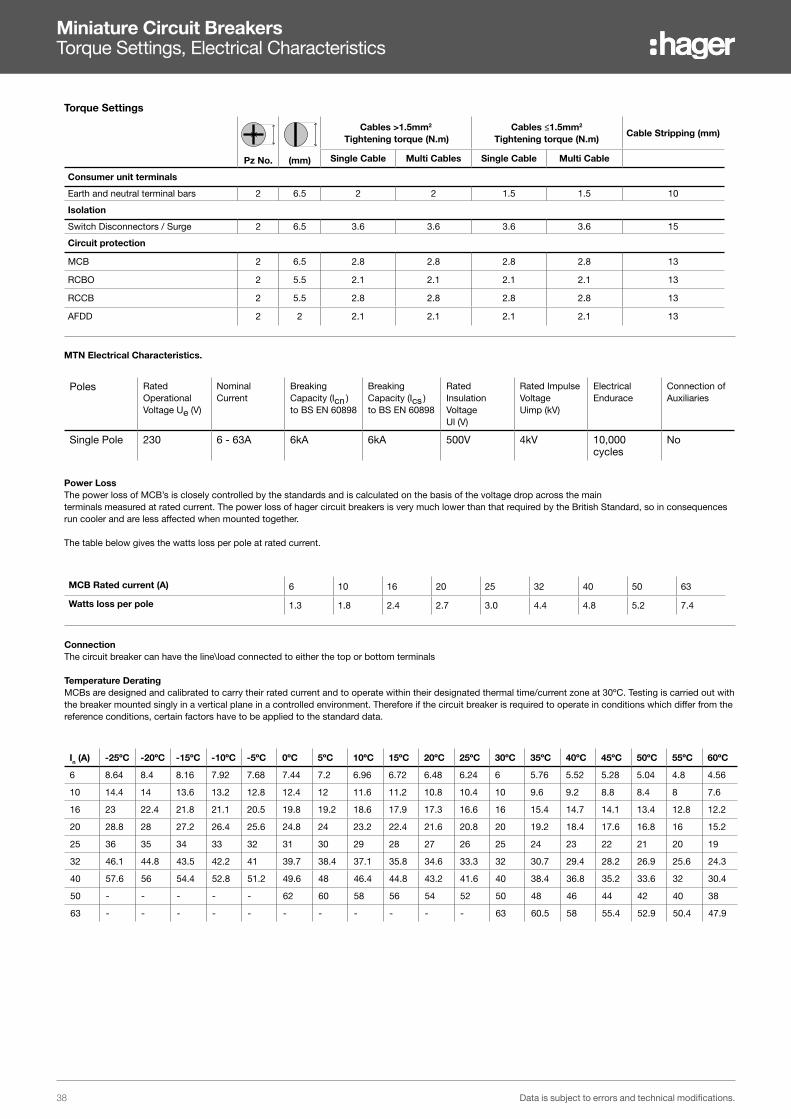
nMiniature Circuit Breakers Torque Settings, Electrical Characteristics
Power LossThe power loss of MCB’s is closely controlled by the standards and is calculated on the basis of the voltage drop across the main terminals measured at rated current. The power loss of hager circuit breakers is very much lower than that required by the British Standard, so in consequences run cooler and are less affected when mounted together.
The table below gives the watts loss per pole at rated current.
MTN Electrical Characteristics.
MCB Rated current (A) 6 10 16 20 25 32 40 50 63
Watts loss per pole 1.3 1.8 2.4 2.7 3.0 4.4 4.8 5.2 7.4
Poles Rated Operational Voltage Ue (V)
Nominal Current
Breaking Capacity (Icn )to BS EN 60898
Breaking Capacity (Ics )to BS EN 60898
Rated Insulation VoltageUl (V)
Rated Impulse VoltageUimp (kV)
Electrical Endurace
Connection of Auxiliaries
Single Pole 230 6 - 63A 6kA 6kA 500V 4kV 10,000 cycles
No
Torque Settings
Pz No. (mm)
Cables >1.5mm2
Tightening torque (N.m)Cables ≤1.5mm2
Tightening torque (N.m)Cable Stripping (mm)
Single Cable Multi Cables Single Cable Multi Cable
Consumer unit terminals
Earth and neutral terminal bars 2 6.5 2 2 1.5 1.5 10
Isolation
Switch Disconnectors / Surge 2 6.5 3.6 3.6 3.6 3.6 15
Circuit protection
MCB 2 6.5 2.8 2.8 2.8 2.8 13
RCBO 2 5.5 2.1 2.1 2.1 2.1 13
RCCB 2 5.5 2.8 2.8 2.8 2.8 13
AFDD 2 2 2.1 2.1 2.1 2.1 13
ConnectionThe circuit breaker can have the line\load connected to either the top or bottom terminals
Temperature DeratingMCBs are designed and calibrated to carry their rated current and to operate within their designated thermal time/current zone at 30ºC. Testing is carried out with the breaker mounted singly in a vertical plane in a controlled environment. Therefore if the circuit breaker is required to operate in conditions which differ from the reference conditions, certain factors have to be applied to the standard data.
In (A) -25ºC -20ºC -15ºC -10ºC -5ºC 0ºC 5ºC 10ºC 15ºC 20ºC 25ºC 30ºC 35ºC 40ºC 45ºC 50ºC 55ºC 60ºC
6 8.64 8.4 8.16 7.92 7.68 7.44 7.2 6.96 6.72 6.48 6.24 6 5.76 5.52 5.28 5.04 4.8 4.56
10 14.4 14 13.6 13.2 12.8 12.4 12 11.6 11.2 10.8 10.4 10 9.6 9.2 8.8 8.4 8 7.6
16 23 22.4 21.8 21.1 20.5 19.8 19.2 18.6 17.9 17.3 16.6 16 15.4 14.7 14.1 13.4 12.8 12.2
20 28.8 28 27.2 26.4 25.6 24.8 24 23.2 22.4 21.6 20.8 20 19.2 18.4 17.6 16.8 16 15.2
25 36 35 34 33 32 31 30 29 28 27 26 25 24 23 22 21 20 19
32 46.1 44.8 43.5 42.2 41 39.7 38.4 37.1 35.8 34.6 33.3 32 30.7 29.4 28.2 26.9 25.6 24.3
40 57.6 56 54.4 52.8 51.2 49.6 48 46.4 44.8 43.2 41.6 40 38.4 36.8 35.2 33.6 32 30.4
50 - - - - - 62 60 58 56 54 52 50 48 46 44 42 40 38
63 - - - - - - - - - - - 63 60.5 58 55.4 52.9 50.4 47.9

39Data is subject to errors and technical modifications.
Res
iden
tial
Dis
trib
utio
n
Surge ProtectionTechnical Information
CharacteristicsSPD’s protect electrical and electronic equipment against transients, originating from lightning, switching of transformers, lighting and motors. These transient voltages can cause premature ageing of equipment, downtime, or complete destruction of electronic components and materials. SPDs are strongly recommended on installations that are exposed to transient voltages, to protect sensitive and expensive electrical equipment such as TV, video, Hi-Fi, PC, alarm etc.
The range of SPDs is separated into 3 types of protection:
1. Main protection - Type 1 SPDs with higher discharge current (Imax 10/350), to evacuate as much of the transient over-voltages associated with lightning strikes
2. Main protection - Type 2 - With a discharge current (Imax 8/20), to evacuate as much of the transient over-voltage to earth as possible protection level (Up ≤ 1200V).
3. Main protection - Type 3 - To cut-down the transient surge as low as possible to protect very sensitive equipment.
Technical Data - Complies with IEC61643-1. - D Versions: end of life indicator, auxiliary contact for remote indication. - R Versions: reserve status indicator, signalling. - Connection Capacity (terminal blocks L, N & E): Rigid conductor:
10mm², Flexible conductor: 6mm². - 230V a.c. 1A. 12V...10mA.
Installation and Connection - The main protection SPDs are installed directly after the main incoming switch or RCCB - Connected in parallel to the equipment to be protected. - Protection is assured in both common and differential modes.
Replacement Cartridges - Allow simple replacement without the need to cut-off the power supply. - Cartridges are available for all discharge currents, (40kA and 15kA) with and without condition indication. - A keying system exists to prevent a line cartridge being interchanged by mistake with a neutral one and visa versa neutral cartridges have a discharge current of 40kA.
Type 1 + 2 (Type 1 + 2 + 3 if less than 5m) (with lifetime indicator)In kA
L-N
In kA
N-PE
IimpL-N
IimpN-PE Up kV Width (mm) Cat ref.
Cat ref.with remote contact
- - 12.5 25 ≤1.5 35 SPA201 -
Type 2 (with lifetime indicator)5 15 - - ≤ 1.0 35 SPD215D SPN215R
15 40 - - ≤ 1.2 35 SPN240D SPN240R
Type 3 (Fine Protection) (with lifetime indicator)3 3 - - ≤ 1.25 17.5 SPN203N -
PV Applications (DC side) (with lifetime indicator)12.5 25 ≤ 4 52.5 SPV325 -
SPN240R
Replacement Cartridges
Description Cat ref.
Line replacement for SPD215D SPD015D
Line replacement for SPN215R SPN015R
Line replacement for SPN240D SPN040D
Line replacement for SPN240R SPN040R
Neutral replacement for SPD215D, SPN215R, SPN240D, SPN240R SPD040N
Neutral replacement for SPN203N SPN023N SPN040D

40 Data is subject to errors and technical modifications.
Res
iden
tial
Dis
trib
utio
nSurge Protection Devices Type 1 + Type 2, SPA201* SPA215
SPA201
Tested to EN 61643-11 2002-12
SPD type / class Type 1 + Type 2
Energy-coordinated protection effect on terminal equipment ≤ 5 m Type 1 + Type 2 + Type 3
Type of connection Parallel connection
Type of power supply system TT / TN system
Type of protection common and differential modes
Nominal voltage Un 230V/400V AC
Rated voltage Uc 255V AC
Voltage protection level Up ≤ 1.5kV
Rated load current I(L) n/a
I(L-L) n/a
Follow current interrupting rating Ifi 25kA rms100A rms
Nominal discharge current (8/20) In 12.5kA25kA
Impulse current (10/350) Iimp 12.5kA25kA
Max. rating of overcurrent protection fuse 160A gL / gG
MCCB 160A
Short-circuit withstand capability with max. overcurrent protection fuse 25kA rms
MCB n/a
Response time tA ≤ 100ns
Operating temperature range - 40°C ….+ 80°C
Indication of SPD disconnector Green/Red flag on L and N
Cross sectional area min 1,5mm2 solid / flexible
max 35mm2 stranded / 25mm2 flexible
Tightening torque for terminals 4 Nm
Mounting on 35mm DIN rail in accordance with EN 60715
Enclosure material grey thermoplastic, UL 94V-0
Degree of protection IP20
Modular width 2
Weight 275 g
Approval marking KEMA
SPN215D/R
Tested to EN 61643-11 (VDE0675-6-11) 2002-12
SPD type Type 2 according to EN 61643-11
SPD class Class II according to IEC 61643-1
Type of connection Parallel connection
Maximum continuous operating voltage Uc Line / Neutral ≤ 255V
Neutral/ PE ≤ 275V
Voltage protection level Up ≤ 1kV
Nominal discharge current (8/20 µs) L-PE
In 5kA
Max. discharge current (8/20 µs) N-PE Imax 15kA
Short-circuit withstand capability with max. overcurrent protection 10kA - 32A
Operating temperature range - 40°C ….+ 80°C
Indication of SPD disconnector Green - Yellow - Red
Cross sectional area min 1,5mm2 solid / flexible
max 35mm2 multi-stranded / 25mm2 flexible
Tightening torque for terminals 4.0 Nm
Mounting on 35mm DIN rail in accordance with EN 60715
Enclosure material grey thermoplastic, UL 94V-0
Degree of protection IP20
Modular width (DIN 43880) 2
Auiliary contact. Voltage/ nominal current (only applicable on the R suffix products)
230V/ 0.5A12Vdc10mA
SPA201 Technical Characteristics
SPN215D/R Technical Characteristics
41Data is subject to errors and technical modifications.
Res
iden
tial
Dis
trib
utio
n
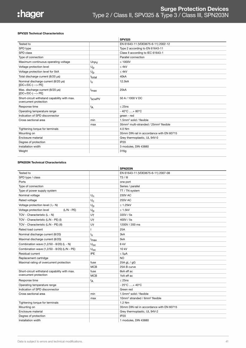
Surge Protection Devices Type 2 / Class II, SPV325 & Type 3 / Class III, SPN203N
SPV325
Tested to EN 61643-11 (VDE0675-6-11) 2002-12
SPD type Type 2 according to EN 61643-11
SPD class Class II according to IEC 61643-1
Type of connection Parallel connection
Maximum continuous operating voltage UcPV ≤ 1000V
Voltage protection level Up ≤ 4kV
Voltage protection level for 5kA Up ≤ 4kV
Total discharge current (8/20 µs) Itotal 40kA
Nominal discharge current (8/20 µs)[(DC+/DC-) --> PE]
In 12.5kA
Max. discharge current (8/20 µs)[(DC+/DC-) --> PE]
Imax 25kA
Short-circuit withstand capability with max. overcurrent protection
IscwPV 50 A / 1000 V DC
Response time tA ≤ 25ns
Operating temperature range - 40°C ….+ 80°C
Indication of SPD disconnector green - red
Cross sectional area min 1.5mm2 solid / flexible
max 35mm2 multi-stranded / 25mm2 flexible
Tightening torque for terminals 4.0 Nm
Mounting on 35mm DIN rail in accordance with EN 60715
Enclosure material Grey thermoplastic, UL 94V-0
Degree of protection IP20
Installation width 3 modules, DIN 43880
Weight 316g
SPN203N
Tested to EN 61643-11 (VDE0675-6-11) 2007-08
SPD type / class T3 / III
Ports one port
Type of connection Series / parallel
Type of power supply system TT / TN system
Nominal voltage Un 230V AC
Rated voltage Uc 255V AC
Voltage protection level ( L- N) Up ≤ 1.25kV
Voltage protection level (L/N - PE) Up ≤ 1.5kV
TOV - Characteristic (L - N) UT 335V / 5s
TOV - Characteristic (L/N - PE) (I) UT 400V / 5s
TOV - Characteristic (L/N - PE) (II) UT 1200V / 200 ms
Rated load current I 25A
Nominal discharge current (8/20) In 3kA
Maximal discharge current (8/20) Imax 5kA
Combination wave (1,2/50 - 8/20) (L - N) Uoc 6 kV
Combination wave (1,2/50 - 8/20) (L/N - PE) Uoc 10 kV
Residual current IPE ≤ 5μA
Replacement cartridge NO
Maximal rating of overcurrent protection fuse 25A gL / gG
MCB 25A B curve
Short-circuit withstand capability with max. overcurrent protection
fuse 6kA eff ac
MCB 1kA eff ac
Response time tA ≤ 25ns
Operating temperature range - 25°C ….+ 40°C
Indication of SPD disconnector Green red
Cross sectional area min 1.5mm2 solid / flexible
max 10mm2 stranded / 6mm2 flexible
Tightening torque for terminals 1.2 Nm
Mounting on 35mm DIN rail in accordance with EN 60715
Enclosure material Grey thermoplastic, UL 94V-2
Degree of protection IP20
Installation width 1 modules, DIN 43880
SPV325 Technical Characteristics
SPN203N Technical Characteristics

42 Data is subject to errors and technical modifications.
Res
iden
tial
Dis
trib
utio
n
Notes

43Data is subject to errors and technical modifications.
Res
iden
tial
Dis
trib
utio
n
Notes

Residential Distribution
Hager Ltd.Hortonwood 50TelfordShropshireTF1 7FT
Customer Contact Centre: 01952 675612Technical Helpline: 01952 675689
hager.com/[email protected]@hager.co.uk
July 2021