catia electrical space reservation - cadcamlab.org space reservation.pdf · pathway reservations...
TRANSCRIPT
CATIA Electrical Space Reservation CATIA® V5R19
Table of Contents, Page i© Wichita State University
TABLE OF CONTENTS
Introduction . . . . . . . . . . . . . . . . . . . . . . . . . . . . . . . . . . . . . . . . . . . . . . . . . . . . . . . . . . . . . . 1Manual Format . . . . . . . . . . . . . . . . . . . . . . . . . . . . . . . . . . . . . . . . . . . . . . . . . . . . . . 2Electrical Reservations . . . . . . . . . . . . . . . . . . . . . . . . . . . . . . . . . . . . . . . . . . . . . . . . 3
Equipment Reservations . . . . . . . . . . . . . . . . . . . . . . . . . . . . . . . . . . . . . . . . . . . . . . . . . . . . 5
Pathway Reservations . . . . . . . . . . . . . . . . . . . . . . . . . . . . . . . . . . . . . . . . . . . . . . . . . . . . . 31
Advanced Reservations . . . . . . . . . . . . . . . . . . . . . . . . . . . . . . . . . . . . . . . . . . . . . . . . . . . . 49
Reservation Analysis . . . . . . . . . . . . . . . . . . . . . . . . . . . . . . . . . . . . . . . . . . . . . . . . . . . . . . 67Clash . . . . . . . . . . . . . . . . . . . . . . . . . . . . . . . . . . . . . . . . . . . . . . . . . . . . . . . . . . . . 69Sectioning . . . . . . . . . . . . . . . . . . . . . . . . . . . . . . . . . . . . . . . . . . . . . . . . . . . . . . . . 73Distance . . . . . . . . . . . . . . . . . . . . . . . . . . . . . . . . . . . . . . . . . . . . . . . . . . . . . . . . . . 863D Annotations . . . . . . . . . . . . . . . . . . . . . . . . . . . . . . . . . . . . . . . . . . . . . . . . . . . . 892D Annotated Views . . . . . . . . . . . . . . . . . . . . . . . . . . . . . . . . . . . . . . . . . . . . . . . . 92
Problems . . . . . . . . . . . . . . . . . . . . . . . . . . . . . . . . . . . . . . . . . . . . . . . . . . . . . . . . . . . . . . . 97Problem #1.0 . . . . . . . . . . . . . . . . . . . . . . . . . . . . . . . . . . . . . . . . . . . . . . . . . . . . . . 97Problem #2.0 . . . . . . . . . . . . . . . . . . . . . . . . . . . . . . . . . . . . . . . . . . . . . . . . . . . . . . 98
Appendix A . . . . . . . . . . . . . . . . . . . . . . . . . . . . . . . . . . . . . . . . . . . . . . . . . . . . . . . . . . . . . 99Infrastructure - Part Infrastructure - General . . . . . . . . . . . . . . . . . . . . . . . . . . . . . . 99Infrastructure - Part Infrastructure - Display . . . . . . . . . . . . . . . . . . . . . . . . . . . . . 100Digital Mockup - General . . . . . . . . . . . . . . . . . . . . . . . . . . . . . . . . . . . . . . . . . . . 101Digital Mockup - DMU Navigator . . . . . . . . . . . . . . . . . . . . . . . . . . . . . . . . . . . . . 102Digital Mockup - DMU Marker . . . . . . . . . . . . . . . . . . . . . . . . . . . . . . . . . . . . . . . 103Digital Mockup - DMU Sectioning . . . . . . . . . . . . . . . . . . . . . . . . . . . . . . . . . . . . 104Digital Mockup - DMU Space Analysis - DMU Clash . . . . . . . . . . . . . . . . . . . . . 105Digital Mockup - DMU Space Analysis - DMU Distance . . . . . . . . . . . . . . . . . . 106
CATIA Electrical Space Reservation CATIA® V5R19
Introduction, Page 1© Wichita State University
Introduction
CATIA Version 5 Electrical Space Reservation
Upon completion of this course the student should have a full understanding of thefollowing topics:
- Defining reservation areas for electrical equipment
- Defining reservation routes for electrical pathways
- Importing reservation areas
- Analyzing the space reservations for clashes and clearance issues
CATIA Electrical Space Reservation CATIA® V5R19
Introduction, Page 2 ©Wichita State University
Manual Format
It is important to understand the format of the manual in order to use it most effectively. This manual is designed to be used along with an instructor; however, you will need to do alot of reading as well, in order to fully understand CATIA Version 5. The exercises in thisbook will list steps for you to complete, along with explanations that try to inform you whatyou have just done and what you are getting ready to do. The actual steps are in bold typeand the information that follows the steps is for your benefit. Anything that appears initalics refers to a message CATIA provides—this includes information in pull-down menus,pop-up windows and other messages.
An example of a step and its explanation is shown below (note: normally the lines will notbe there):
Select a location to the right of the origin. This specifies the other end point of the line. You will continue specifying locations in order to complete your profile. It should appearsimilar to the diagram shown below.
As you can see, the desired action blends in with the text except that it appears in bold. Theinformation following the step explains what that step accomplished and where you aregoing next. It is important for you to read this information to help in your understanding ofCATIA Version 5.
Also, you will find that the exercises build upon themselves. Later exercises often assumeyou know how to do certain steps which have been covered in earlier exercises. If you didnot quite pick up what you needed to know from an exercise, you will probably wish toreview it several times before moving on to the more advanced sections. As you progressthrough the manual, it expects that you are learning and therefore you are able to do a lotmore with fewer steps. Eventually, you are expected to be able to perform previous taskswithout any steps.
CATIA Electrical Space Reservation CATIA® V5R19
Introduction, Page 3© Wichita State University
Electrical Reservations
Creating an electrical reservation involves creating shapes and areas that will act as akeep-out zone or an area to avoid for other disciplines. Although CATIA V5 has a productfor Systems Space Reservations, you are limited to creating reservations that are only simpleshapes. Many times you will have a complex shape to conform to and will be unable toaccurately model and describe the space reservation through blocks and circular tubes. It isfor this reason that most of the time space reservations are made via part design andwireframe shapes and objects. These objects allow for a more complex definition of thearea to be reserved.
This course builds upon your knowledge of Part Design and Sketcher, Wireframe andSurfaces, as well as Assembly Design. All three of these topics will be used to define theelectrical reservations.
CATIA Electrical Space Reservation CATIA® V5R19
Pathway Reservations, Page 31© Wichita State University
Pathway Reservations
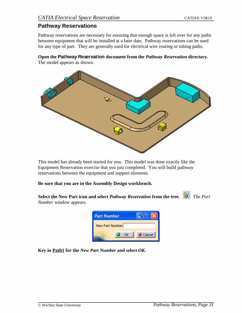
Pathway reservations are necessary for ensuring that enough space is left over for any pathsbetween equipment that will be installed at a later date. Pathway reservations can be usedfor any type of part. They are generally used for electrical wire routing or tubing paths.
Open the Pathway Reservation document from the Pathway Reservation directory. The model appears as shown.
This model has already been started for you. This model was done exactly like theEquipment Reservation exercise that you just completed. You will build pathwayreservations between the equipment and support elements.
Be sure that you are in the Assembly Design workbench.
Select the New Part icon and select Pathway Reservation from the tree. The PartNumber window appears.
Key in Path1 for the New Part Number and select OK.
CATIA Electrical Space Reservation CATIA® V5R19
Pathway Reservations, Page 32 ©Wichita State University
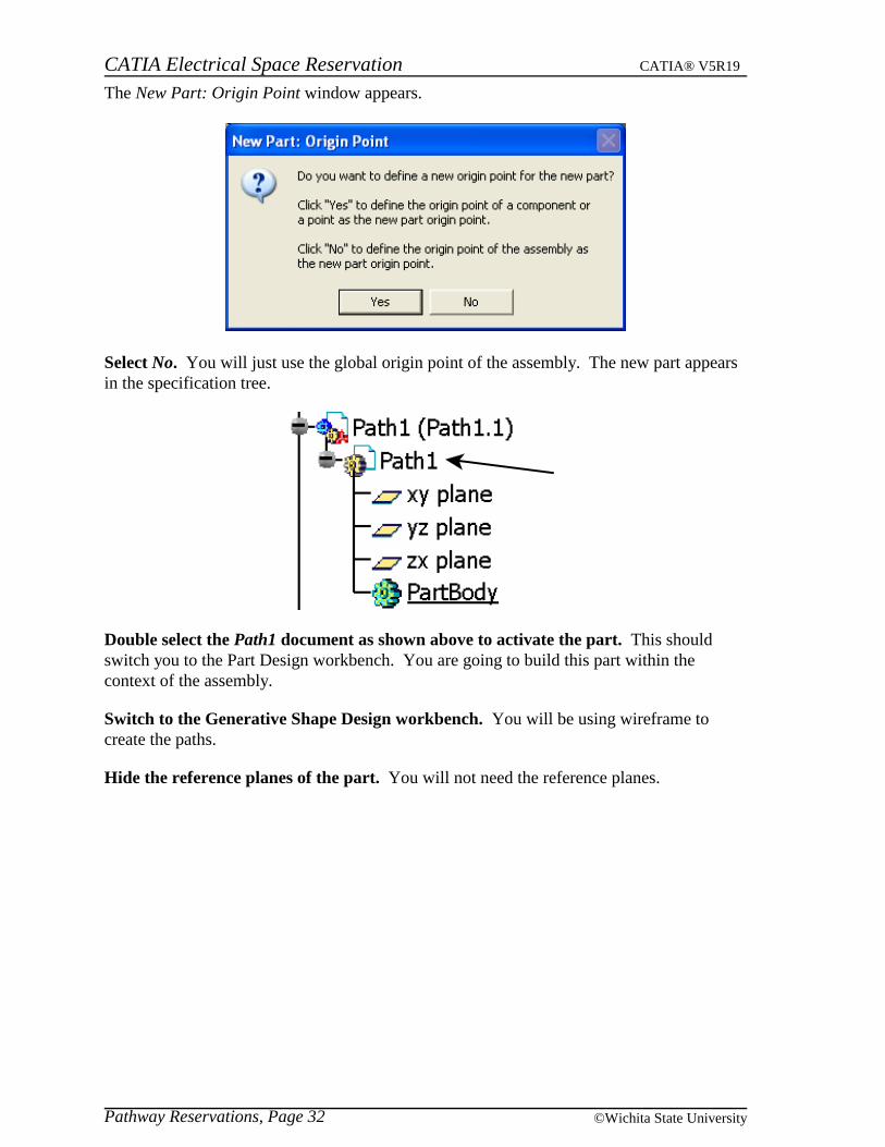
The New Part: Origin Point window appears.
Select No. You will just use the global origin point of the assembly. The new part appearsin the specification tree.
Double select the Path1 document as shown above to activate the part. This shouldswitch you to the Part Design workbench. You are going to build this part within thecontext of the assembly.
Switch to the Generative Shape Design workbench. You will be using wireframe tocreate the paths.
Hide the reference planes of the part. You will not need the reference planes.
CATIA Electrical Space Reservation CATIA® V5R19
Pathway Reservations, Page 33© Wichita State University
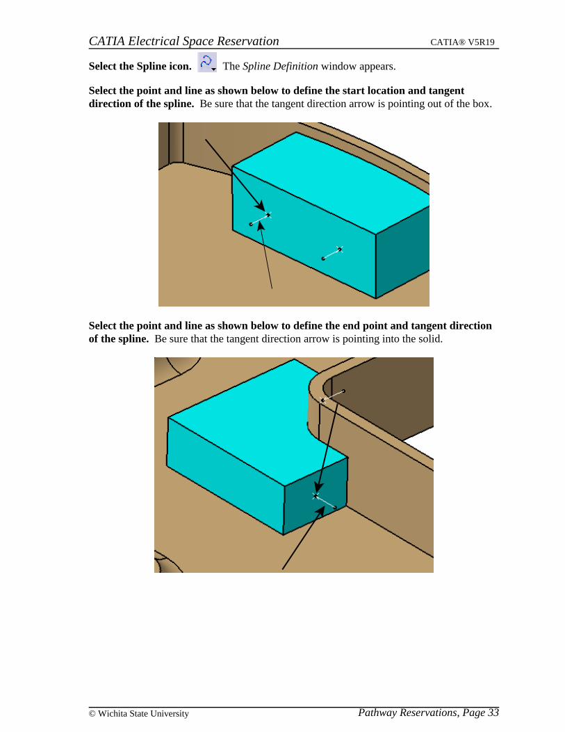
Select the Spline icon. The Spline Definition window appears.
Select the point and line as shown below to define the start location and tangentdirection of the spline. Be sure that the tangent direction arrow is pointing out of the box.
Select the point and line as shown below to define the end point and tangent directionof the spline. Be sure that the tangent direction arrow is pointing into the solid.
CATIA Electrical Space Reservation CATIA® V5R19
Pathway Reservations, Page 34 ©Wichita State University
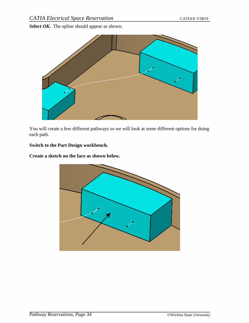
Select OK. The spline should appear as shown.
You will create a few different pathways so we will look at some different options for doingeach path.
Switch to the Part Design workbench.
Create a sketch on the face as shown below.
CATIA Electrical Space Reservation CATIA® V5R19
Pathway Reservations, Page 35© Wichita State University
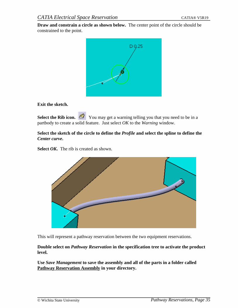
Draw and constrain a circle as shown below. The center point of the circle should beconstrained to the point.
Exit the sketch.
Select the Rib icon. You may get a warning telling you that you need to be in apartbody to create a solid feature. Just select OK to the Warning window.
Select the sketch of the circle to define the Profile and select the spline to define theCenter curve.
Select OK. The rib is created as shown.
This will represent a pathway reservation between the two equipment reservations.
Double select on Pathway Reservation in the specification tree to activate the productlevel.
Use Save Management to save the assembly and all of the parts in a folder calledPathway Reservation Assembly in your directory.
CATIA Electrical Space Reservation CATIA® V5R19
Pathway Reservations, Page 36 ©Wichita State University
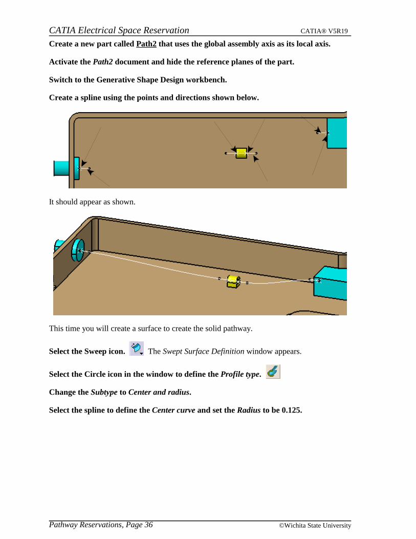
Create a new part called Path2 that uses the global assembly axis as its local axis.
Activate the Path2 document and hide the reference planes of the part.
Switch to the Generative Shape Design workbench.
Create a spline using the points and directions shown below.
It should appear as shown.
This time you will create a surface to create the solid pathway.
Select the Sweep icon. The Swept Surface Definition window appears.
Select the Circle icon in the window to define the Profile type.
Change the Subtype to Center and radius.
Select the spline to define the Center curve and set the Radius to be 0.125.
CATIA Electrical Space Reservation CATIA® V5R19
Pathway Reservations, Page 37© Wichita State University
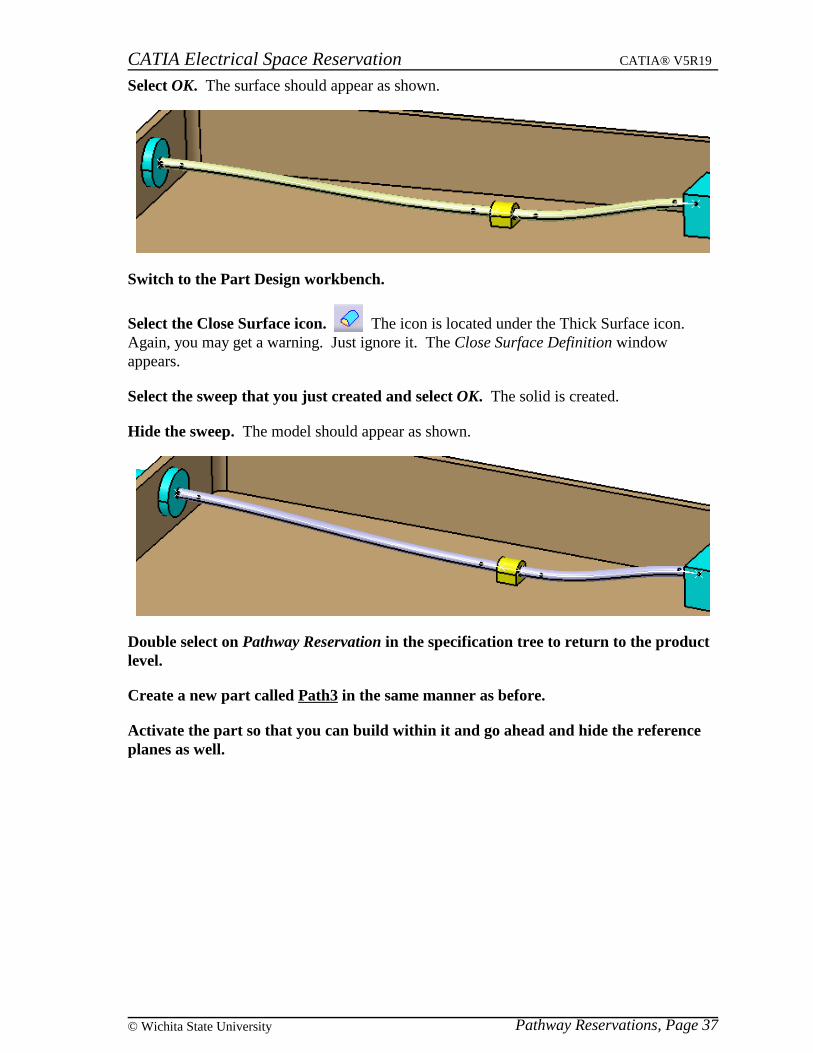
Select OK. The surface should appear as shown.
Switch to the Part Design workbench.
Select the Close Surface icon. The icon is located under the Thick Surface icon. Again, you may get a warning. Just ignore it. The Close Surface Definition windowappears.
Select the sweep that you just created and select OK. The solid is created.
Hide the sweep. The model should appear as shown.
Double select on Pathway Reservation in the specification tree to return to the productlevel.
Create a new part called Path3 in the same manner as before.
Activate the part so that you can build within it and go ahead and hide the referenceplanes as well.
CATIA Electrical Space Reservation CATIA® V5R19
Pathway Reservations, Page 38 ©Wichita State University
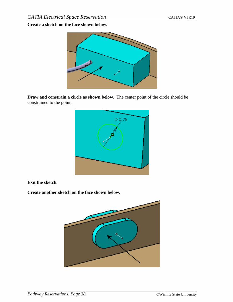
Create a sketch on the face shown below.
Draw and constrain a circle as shown below. The center point of the circle should beconstrained to the point.
Exit the sketch.
Create another sketch on the face shown below.
CATIA Electrical Space Reservation CATIA® V5R19
Pathway Reservations, Page 39© Wichita State University
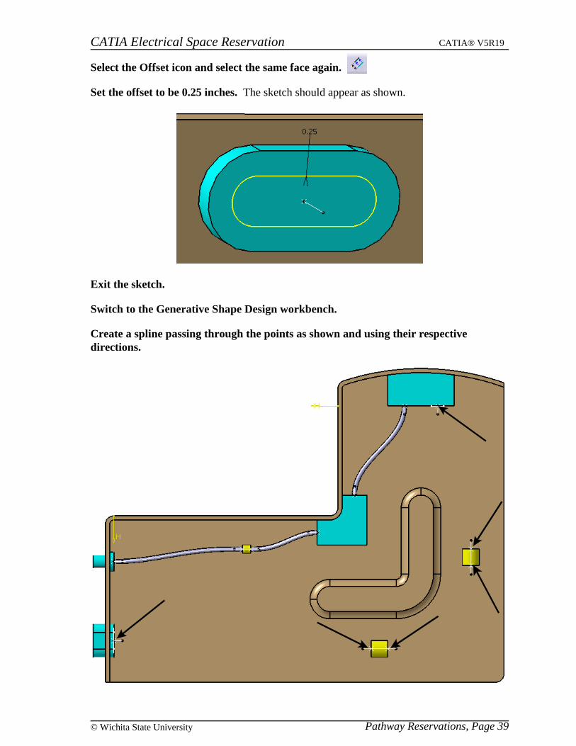
Select the Offset icon and select the same face again.
Set the offset to be 0.25 inches. The sketch should appear as shown.
Exit the sketch.
Switch to the Generative Shape Design workbench.
Create a spline passing through the points as shown and using their respectivedirections.
CATIA Electrical Space Reservation CATIA® V5R19
Pathway Reservations, Page 40 ©Wichita State University
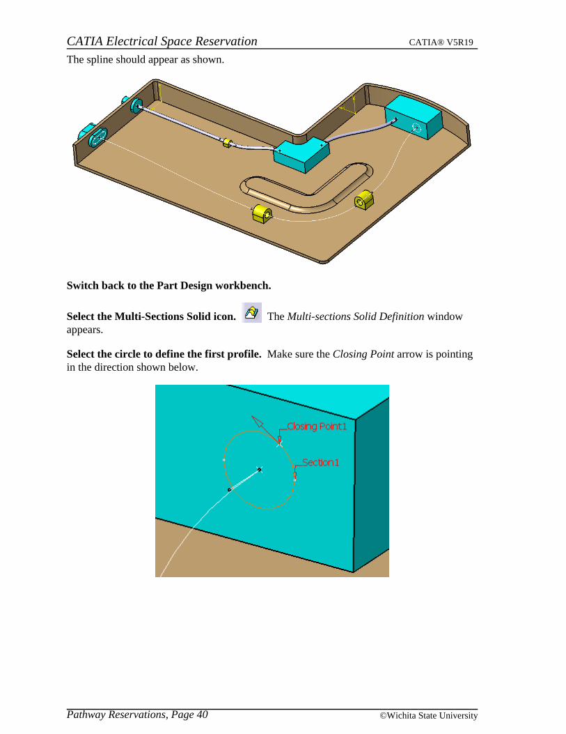
The spline should appear as shown.
Switch back to the Part Design workbench.
Select the Multi-Sections Solid icon. The Multi-sections Solid Definition windowappears.
Select the circle to define the first profile. Make sure the Closing Point arrow is pointingin the direction shown below.
CATIA Electrical Space Reservation CATIA® V5R19
Pathway Reservations, Page 41© Wichita State University
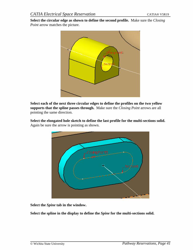
Select the circular edge as shown to define the second profile. Make sure the ClosingPoint arrow matches the picture.
Select each of the next three circular edges to define the profiles on the two yellowsupports that the spline passes through. Make sure the Closing Point arrows are allpointing the same direction.
Select the elongated hole sketch to define the last profile for the multi-sections solid. Again be sure the arrow is pointing as shown.
Select the Spine tab in the window.
Select the spline in the display to define the Spine for the multi-sections solid.
CATIA Electrical Space Reservation CATIA® V5R19
Pathway Reservations, Page 42 ©Wichita State University
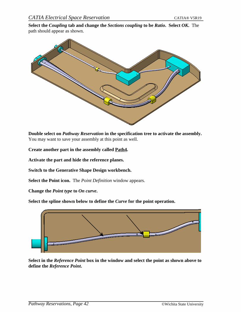
Select the Coupling tab and change the Sections coupling to be Ratio. Select OK. Thepath should appear as shown.
Double select on Pathway Reservation in the specification tree to activate the assembly. You may want to save your assembly at this point as well.
Create another part in the assembly called Path4.
Activate the part and hide the reference planes.
Switch to the Generative Shape Design workbench.
Select the Point icon. The Point Definition window appears.
Change the Point type to On curve.
Select the spline shown below to define the Curve for the point operation.
Select in the Reference Point box in the window and select the point as shown above todefine the Reference Point.
CATIA Electrical Space Reservation CATIA® V5R19
Pathway Reservations, Page 43© Wichita State University
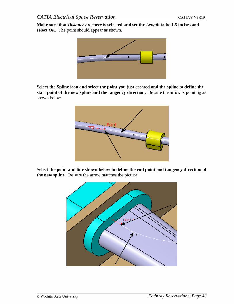
Make sure that Distance on curve is selected and set the Length to be 1.5 inches andselect OK. The point should appear as shown.
Select the Spline icon and select the point you just created and the spline to define thestart point of the new spline and the tangency direction. Be sure the arrow is pointing asshown below.
Select the point and line shown below to define the end point and tangency direction ofthe new spline. Be sure the arrow matches the picture.
CATIA Electrical Space Reservation CATIA® V5R19
Pathway Reservations, Page 44 ©Wichita State University
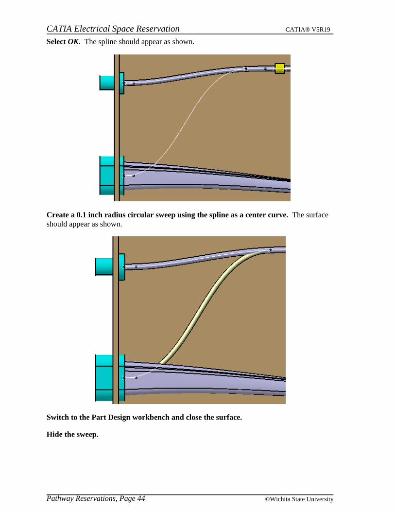
Select OK. The spline should appear as shown.
Create a 0.1 inch radius circular sweep using the spline as a center curve. The surfaceshould appear as shown.
Switch to the Part Design workbench and close the surface.
Hide the sweep.
CATIA Electrical Space Reservation CATIA® V5R19
Pathway Reservations, Page 45© Wichita State University
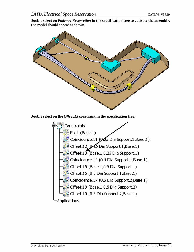
Double select on Pathway Reservation in the specification tree to activate the assembly. The model should appear as shown.
Double select on the Offset.13 constraint in the specification tree.
CATIA Electrical Space Reservation CATIA® V5R19
Pathway Reservations, Page 46 ©Wichita State University
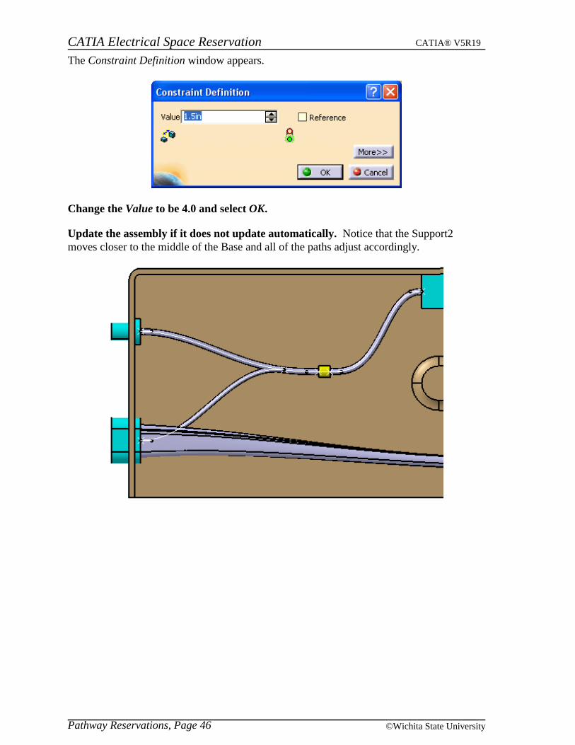
The Constraint Definition window appears.
Change the Value to be 4.0 and select OK.
Update the assembly if it does not update automatically. Notice that the Support2moves closer to the middle of the Base and all of the paths adjust accordingly.
CATIA Electrical Space Reservation CATIA® V5R19
Pathway Reservations, Page 47© Wichita State University
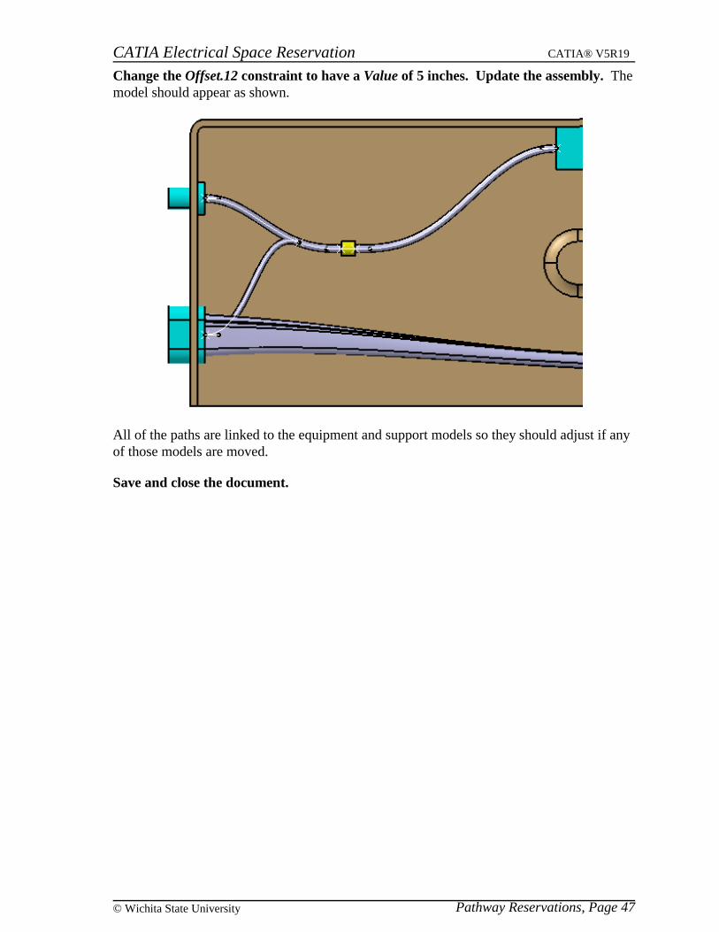
Change the Offset.12 constraint to have a Value of 5 inches. Update the assembly. Themodel should appear as shown.
All of the paths are linked to the equipment and support models so they should adjust if anyof those models are moved.
Save and close the document.