ccpw cad standards manual 2019 - coconino.az.gov
TRANSCRIPT

Coconino CountyEngineering
CADD Manual
5600 East Commerce
5600 East Commerce
Flagstaff, Arizona 86004
(928) 679-8300 Office
(928) 679-8301 Fax
Revised April 10, 2019
EngineeringCADDManual
ENGINEERING CADD STANDARDS
Chapter 1 CADD Practice
1.1 Objective………………………………………………………………. 1
1.2 Maintenance and Editing………………………………………………. 1
Chapter 2 CADD Drawing Guidelines
2.1 General Requirements…………………………………………………...2
2.2 Cover Sheet Presentation……...…………………………………………3
2.3 Survey Control Plan……………………………………………………...3
2.4 Paving Plans…………….………………………………………….…….4
2.5 Grading Plans……………………………………………………….........5
2.6 Sewer Plans……………………………………………………………....5
2.7 Water Plans………………………………………………………………6
2.8 Detail and Section Plans……………………………………………........7
2.9 Revisions and Drawing File Procedures………………………………....7
2.10 Markup Guidelines……………………………………………………....8
Chapter 3 Engineering Standards
3.1 Standard Abbreviations and Symbols ……………………………….......9
3.2 Line types……………………………………………………………......22
3.3 Lettering, Linework and Data…………………………………………...23

EngineeringCADDStandards
ENGINEERINGCADDSTANDARDS
Page1
Chapter 1 CADD Practice
1.1 Objective
The objective of these Coconino County Public Works CADD (Computer Aided Drafting and Design) Standards is to help provide uniformity of process and presentation. This objective is achieved through standards and guidelines for folder format, file naming, content and the process by which the data is created and saved. Adherence to these standards can help to avoid confusion between workgroups and increase individual efficiency. It can also provide the following:
• Uniformity • Ensure integrity • Build clarity • Simplify creation/modification • Promote interchangeability • Streamline workflow • Improve communication • Integrate new users more quickly • Simplify procedures • Increase efficiency
1.2 Maintenance & Editing
The CADD Standards are not intended to be static and can be enhanced and updated. Suggestions for improvements are strongly encouraged which would allow subsequent CADD Standard Manuals to reflect both the input and needs of the professional CADD user. Surveyors, Engineers, Designers and other users may have differing needs and therefore may require modifications to best serve their applications.

EngineeringCADDStandards
ENGINEERINGCADDSTANDARDS
Page2
Chapter 2 CADD Drawing Guidelines
2.1 General Requirements
A. General Drafting Guidelines North arrows should be oriented up or to the left as often as possible.
Direction of north arrows will also be determined by stationing with increasing stationing from west to east and south to north
Create civil design in model space at 1 drawing unit=1 foot, structural and architectural design and details shall be 1 drawing unit=1 inch
Abbreviations should be shown in accordance with County Standards The size of lettering and symbols shall be no smaller than 1/8 inch (.12 or
L120) Plan sheets shall be 24” x 36” and sufficiently clear to allow for legible prints
B. Sheet File Name Conventions
Sheet names for drawings and other engineering related documents will be a combination of the project name, descriptor, sheet number and type. Project Numbers may also be incorporated but are not necessary. The following is an example:
CIP NAME DESCRIPTION SHT NO TYPE.dwg
TURKEY TRAIL DRAINAGE IMPROVEMENTS SHT04 PP01-AB.dwg
C. Title Blocks
Title blocks shall contain the following:
Project title Sheet title Project location Sheet numbers (sheet # of #) Job number Professional seal (seal must be signed if plans are complete) Designer, drafter and checker initials Scale (horizontal and vertical if applicable; for example: H. 1" = 20', V. 1" = 10'). If drawing has no scale, write NONE or NTS. If drawing has various scales, write AS
NOTED in title block and write the scales under the view titles. Revisions block

EngineeringCADDStandards
ENGINEERINGCADDSTANDARDS
Page3
2.2 Cover Sheet Presentation
A cover sheet is required on all plans with more than two sheets. The cover sheet should be sheet #1 and contain the following:
Project title with name and location of project Indicate plan type (Paving plan, Water Plan, Final Plat etc.) Vicinity Map with north arrow Location map Basis of Bearing Block including:
o Basis of bearing description o Description of monuments used for basis of bearing o Coordinates on each monument used for basis of bearing
Vertical datum note, including: o Benchmark reference number, description (including location), and elevation o Datum name
Detail & section referencing block Sheet index (may go on another sheet if more room is required) Blue Stake notification decal Owner/Developer name, address and telephone number Engineers name, address and phone number Legend with symbols, lines, etc. Approval block for Utilities Approval block for County Engineers’ signature
2.3 Survey Control Plan
Survey control information should be included in every plan set. The survey control information may be included on the location map or may be shown on its’ own sheet. The survey control information sheet must include:
Street names Description of every monument (cased, buried, surface brass cap, etc.) Coordinates for each monument, which must include Northing and Easting Bearing and distance on each street between each two monuments, and distance
from offset monument (if any) to intersection Radius, delta angle, and arc length on any curving monument lines or baselines Bearing and distance and/or dimension from monumented line to construction
baselines (if any) Stations at intersections and all monuments
EngineeringCADDStandards
ENGINEERINGCADDSTANDARDS
Page4
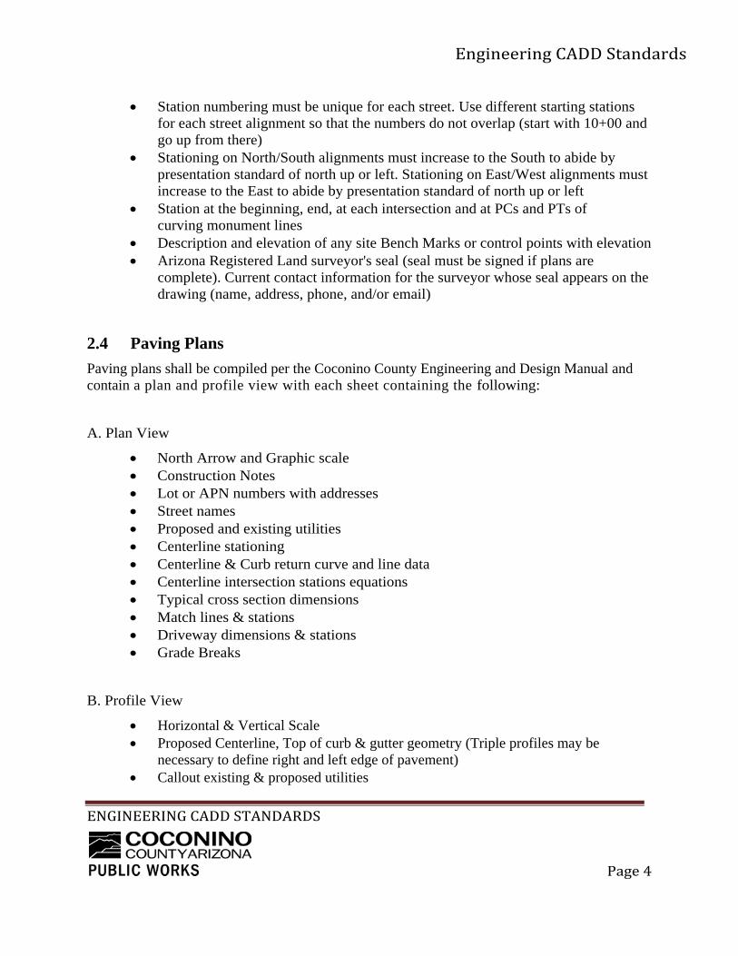
Station numbering must be unique for each street. Use different starting stations for each street alignment so that the numbers do not overlap (start with 10+00 and go up from there)
Stationing on North/South alignments must increase to the South to abide by presentation standard of north up or left. Stationing on East/West alignments must increase to the East to abide by presentation standard of north up or left
Station at the beginning, end, at each intersection and at PCs and PTs of curving monument lines
Description and elevation of any site Bench Marks or control points with elevation Arizona Registered Land surveyor's seal (seal must be signed if plans are
complete). Current contact information for the surveyor whose seal appears on the drawing (name, address, phone, and/or email)
2.4 Paving Plans
Paving plans shall be compiled per the Coconino County Engineering and Design Manual and contain a plan and profile view with each sheet containing the following:
A. Plan View
North Arrow and Graphic scale Construction Notes Lot or APN numbers with addresses Street names Proposed and existing utilities Centerline stationing Centerline & Curb return curve and line data Centerline intersection stations equations Typical cross section dimensions Match lines & stations Driveway dimensions & stations Grade Breaks
B. Profile View
Horizontal & Vertical Scale Proposed Centerline, Top of curb & gutter geometry (Triple profiles may be
necessary to define right and left edge of pavement) Callout existing & proposed utilities

EngineeringCADDStandards
ENGINEERINGCADDSTANDARDS
Page5
Label proposed grades Label grade breaks station & elevation Show elevations at all “match existing” points Label valley gutter grades Label curb returns station & elevations Label centerline intersections station equations & elevations Provide vertical curve information
2.5 Grading Plans
North Arrow & Graphic Scale Legend Construction Notes Earthwork volumes for Cut/Fill Floodway/Floodplain Boundaries (where applicable) Lot Numbers & Address Proposed & Existing Utilities Typical Cross Sections & Section Details Street names Callouts for Top of Curb, Flow line, Finish Grades, Finish Floor Proposed & Existing Contours Callouts for Street Grades & Ditches w/ flow arrows Grade break Symbols Match lines
2.6 Sanitary Sewer Plans A. Plan View
North Arrow Graphic vertical & horizontal scale Lot Numbers & addresses Street names Proposed Sewer line & taps Flow arrows Existing & Proposed utilities w/ size, type & location Sewer Easements & Rights-of Way dimensions Easement instrument number, Doc and Page Manhole Rim & flow line Callouts (No., Sta., Elev) Construction Notes

EngineeringCADDStandards
ENGINEERINGCADDSTANDARDS
Page6
Sewer tap Stationing Dimension Sewer taps from Property Line Match Lines Dimension Sewer Line from CL Road CL Road data Sewer line horizontal separation from other utilities Sewer Line Stationing is always from downstream to upstream
B. Profile View
Horizontal & Vertical Scale Existing & proposed surface grades @ centerline of pipe Existing & proposed utilities size & location Label proposed total pipe length & slopes ft/ft Label pipe size and materials Label Manhole Size, Station and Rim, Invert, & lateral Elevations Show Vertical separation from existing & proposed utilities Match Lines
2.7 Water Plans
A. Plan View North Arrow Graphic Scale Lot Numbers & Address Street Names Proposed Water line & Services Existing & Proposed Utilities (size, type, location) Water Line Easements & PUE’s Station / Offset Hydrants Water Main location & Dimensions from CL CL Road Data Construction Notes Match Lines
B. Profile View Horizontal & Vertical Scale Existing & proposed grades @ centerline of pipe Existing & proposed utilities size & location

EngineeringCADDStandards
ENGINEERINGCADDSTANDARDS
Page7
Label proposed total pipe length, size, material & slopes ft/ft Label Fitting Station & Offset Show Vertical separation from existing & proposed utilities
2.8 Details & Section Plans
Details should be drawn to scale and typically dimensioned in an architectural format
There are two types of Sections: “civil sections” and “detail sections” Civil sections relate to a plan view and are dimensioned in an engineering format Detail sections relate to a detail view and are dimensioned in an architectural format Label details and sections with a title, scale, reference number and page
2.9 Revisions and Drawing Filing Procedures
A. Addenda - Creating an Addendum Drawing Addenda are made after general distributions and project advertisement but
before the bid opening. B. Revise Drawing
Revise drawing and place a revision delta near each change. Draw revision cloud around revise area, on separate "revision cloud" layer. Remove any previous revision cloud.
C. Update Revision Block Fill out revision block in ascending order. Add revision delta to the revision block; describe revision, type initials for "approved by" and "date" (e.g. 5/96).
D. Issue Drawing Plot drawing
E. As-built Plan As-built plans are plans of record and the final update of the drawings, they
reflect how the project was acconstructed. Normally they contain the original plan identification followed by an “-AB” distinction. An engineers’ seal is needed for all As-builts and revisions.
All revisions require a seal specific to the change. If revisions are approved by anybody other than the original registrant, a new seal by the approving registrant is required. This may be the case where plans sit dormant after completion and before construction.

EngineeringCADDStandards
ENGINEERINGCADDSTANDARDS
Page8
2.10 Markup Guidelines
Drawings can be plotted digitally or physically for review and mark up. Handwriting must be legible and clear. For clear written communication, it is recommend using the following colors
RED new/revised linework or text to be added/modified in dwg GREEN deletions BLUE clarifying comments to CAD technician
It is also useful to highlight edits over the mark-up with a highlighter to indicate that the issue has been addressed and for later reference.

EngineeringCADDStandards
ENGINEERINGCADDSTANDARDS
Page9
Chapter 3 Engineering Standards
3.1 Abbreviations
A. General
Abbreviations, as a rule, are to be avoided. Different words sometimes have identical abbreviations or acronyms, others are unfamiliar or confusing. The word should be spelled out where the meaning may be in doubt.
Abbreviations and acronyms m a y need to be spelled out on first reference Apostrophes are usually not used. Exceptions: pav't., req'd, etc. Abbreviations for plurals are usually the same as the singular. Exceptions: figs.,
nos., pp. etc.
Abbreviations and acronyms are constantly used and easy to misconstrue there for the “when in doubt spell it out” rule should apply. However, when the following abbreviations are used in these specifications, standard details or on the plans, they are to be construed the same as the respective expressions represented below.
B. Abbreviations:
A Architectural
AAC Arizona Administrative Code
AAN American Association of Nurserymen
AASHTO American Association of State Highway and Transportation Officials
AB Aggregate base
Aban Abandon
ABC Aggregate base course
AC Asphalt cement or concrete
ACB Asphalt concrete base
ACI American Concrete Institute
ACP Asbestos cement pipe
ACPA American Concrete Pipe Association
ACWS Asphalt Concrete Wearing Surface

EngineeringCADDStandards
ENGINEERINGCADDSTANDARDS
Page10
ADEQ Arizona Department of Environmental Quality
ADOT Arizona Department of Transportation
AEC Arizona Electric Code
AFRB Arizona Fire Rating Bureau
AGA American Gas Association
AGC Associated General Constructors of America, Inc.
Agg Aggregate
Ahd Ahead
AIA American Institute of Architects
AIEE American Institute of Electrical Engineers
AISC American Institute of Steel Construction
ALIN Alignments
ANNO Annotation
ANSI American National Standards Institute
APA American Plywood Association
Approx Approximate
APWA American Public Works Association
AR Aged residue
ARS Arizona Revised Statues
ASCE American Society of Civil Engineers
ASME American Society of Mechanical Engineers
Asph Asphalt
ASTM American Society for Testing Materials
Ave Avenue
AWPA American Wood Preservers Association
AWSC American Welding Society Code
AWWA American Water Works Association
B
BC Beginning of curve
BCR Beginning of curb return

EngineeringCADDStandards
ENGINEERINGCADDSTANDARDS
Page11
Beg Beginning
Bk Book or Back
BLDG Building
Blvd Boulevard
BM Bench Mark or Board Measure
BNDY Boundary
BORE Test Borings
Brg Bearing
BRIDGE Bridges
BRKL Break/ Fault lines
Brl Barrel
BST Bituminous Surface Treatment
BTB Bituminous Treated Base
BTU British Thermal Units
BVC Beginning of Vertical Curve
C
C Centigrade or Curb
C Civil
CAD Computer Aided Drafting
CB Catch Basin
CBF&C Catch basin frame & cover
CC or C/C Center to Center
CCR Coconino County Records
CE County Engineer
CF Curb Face
cfs Cubic Feet per second
CHAN Channels
CIP Cast Iron pipe
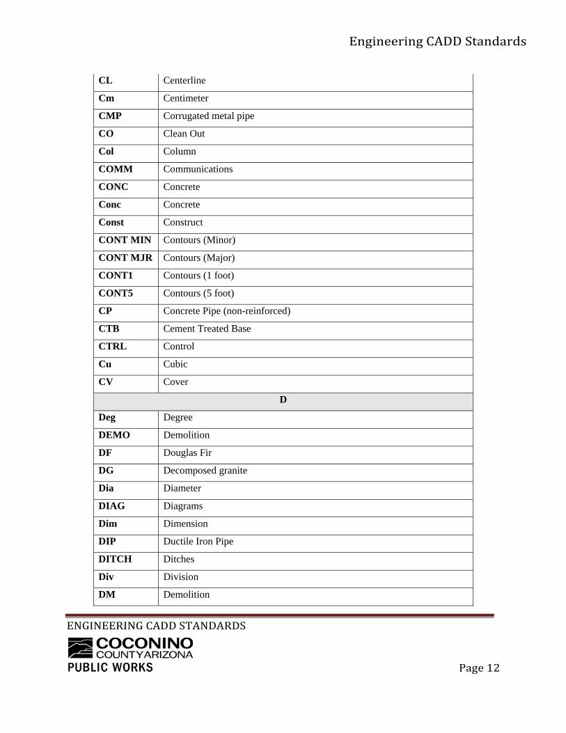
CL Centerline
EngineeringCADDStandards
ENGINEERINGCADDSTANDARDS
Page12
CL Centerline
Cm Centimeter
CMP Corrugated metal pipe
CO Clean Out
Col Column
COMM Communications
CONC Concrete
Conc Concrete
Const Construct
CONT MIN Contours (Minor)
CONT MJR Contours (Major)
CONT1 Contours (1 foot)
CONT5 Contours (5 foot)
CP Concrete Pipe (non-reinforced)
CTB Cement Treated Base
CTRL Control
Cu Cubic
CV Cover
D
Deg Degree
DEMO Demolition
DF Douglas Fir
DG Decomposed granite
Dia Diameter
DIAG Diagrams
Dim Dimension
DIP Ductile Iron Pipe
DITCH Ditches
Div Division
DM Demolition
EngineeringCADDStandards
ENGINEERINGCADDSTANDARDS
Page13
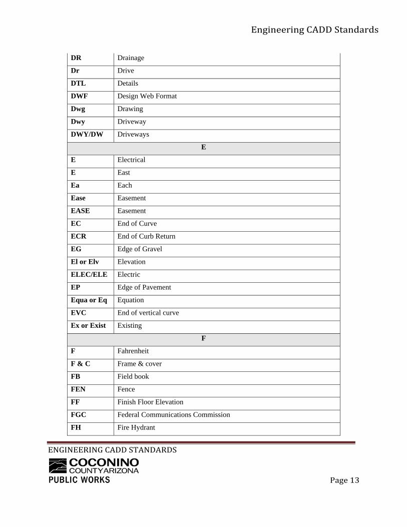
DR Drainage
Dr Drive
DTL Details
DWF Design Web Format
Dwg Drawing
Dwy Driveway
DWY/DW Driveways
E
E Electrical
E East
Ea Each
Ease Easement
EASE Easement
EC End of Curve
ECR End of Curb Return
EG Edge of Gravel
El or Elv Elevation
ELEC/ELE Electric
EP Edge of Pavement
Equa or Eq Equation
EVC End of vertical curve
Ex or Exist Existing
F
F Fahrenheit
F & C Frame & cover
FB Field book
FEN Fence
FF Finish Floor Elevation
FGC Federal Communications Commission
FH Fire Hydrant

EngineeringCADDStandards
ENGINEERINGCADDSTANDARDS
Page14
FHWA Federal Highway Administration
FL or F Floor line or flow line
FLOOD Flood Hazard Area
Fnd Found
FNDN Foundation
FP Finish Pad Elevation
fps Feet per second
FS Finished surface
FSS Federal Specifications and Standards
Ft Foot or feet
G
G Gutter
G General Data
Ga Gage
Galv Galvanized
GAS Gas lines
GD Grading
GDBP Proposed Grading & Drainage
GIS Geographic Information System
GL Ground line
GN General Notes
gpm Gallons Per Minute
Gr Grade
GRID Profile Grid
H
H Hatch
H High or height
HB Hose Bib
HC House connection
Hdwl Headwall

EngineeringCADDStandards
ENGINEERINGCADDSTANDARDS
Page15
Horiz Horizontal
HVAC Heating, ventilation & air conditioning
Hwy Highway
HZ Horizontal Control
ICA Industrial Commission of Arizona
I
ID Improvement District or inside diameter
IEEE Institute of Electrical and Electronic Engineers
In Inch
Inv/IE Invert or Invert Elevation
IP Iron Pipe
IRRG Irrigation

EngineeringCADDStandards
ENGINEERINGCADDSTANDARDS
Page16
J
JC Junction Chamber
Jct Junction
JS Junction Structure
Jt Joint
L
L Length
Lat Latitude
Lb Pound
LF Linear Feet
Lft Left
LIMITS Construction Limits
LLCG Lot lines, curb & gutter
Long Longitude
LOT Lot lines
LS Landscape
M
M Mechanical
MAG Maricopa Association of Governments
Max Maximum
Meas Measured
MH Manhole
Min Minutes or Minimum
Misc Miscellaneous
mm Millimeter
Mon Monument
MUTCO Manual on Uniform Traffic Control Devices
N
N North
NBS National Bureau of Standards

EngineeringCADDStandards
ENGINEERINGCADDSTANDARDS
Page17
NCPI National Clay Pipe Institute
NE Northeast
NEC National Electric Code
NEMA National Electrical Manufacturer’s Association
NFPA National Fire Protection Association
No Number
NP Non-Plastic
NPI Non-Pay Item
NSC National Safety Council
NSF National Sanitation Foundation
NW Northwest
O
OC On center
OD Outside diameter
OSHA Occupational Safety and Health Administration
Oz Ounces
P
P Proposed
PAV Pavement
PC Point of curvature
PCC Point of compound curve
PI Point of intersection or plastic index
PIPE Pipes
PL Property line
PM Project Manager
PNT ELEV Point elevations
POC Point of Curve
POND Ponds
POS Point of Spiral
PP Plan & Profile

EngineeringCADDStandards
ENGINEERINGCADDSTANDARDS
Page18
PP Power pole
ppm Parts Per Million
PRBP Propo overall base
PRC Point of reverse curve
PRKG Parking
PROF Profile
Prop Property
psf Pounds per square foot
psi Pounds per square inch
PT or POT Point of Tangent
PTS Points
PV Paving
Pvmt Pavement
PWR Power
Q Rate of Flow
R
R or RAD Radius
R/W or ROW Right-of-Way
RBAR Rebar
RC Reinforced concrete
RCP Reinforced concrete pipe
Rd Road
RD Roadway
Rdwy Roadway
Reinf Reinforced, Reinforcing
Ret Wall Retaining Wall
RGRCP Rubber Gasket Reinforced Concrete Pipe
RIVER River
ROCK Rock
ROW Right of Way

EngineeringCADDStandards
ENGINEERINGCADDSTANDARDS
Page19
rpm Revolutions Per Minute
RR Railroad tracks, structures
Rt Right
S
S South or slope
S Structural
SAE Society of Automotive Engineers
San Sanitary
SC Spiral to Curve
SD Storm Drain or Sewer District
SD Storm Drainage
SDWK Sidewalk
SE Southeast
SEC Sections
Sec Seconds or Section
Sht Sheet
SP Site Plan
Spec or Specs Specifications
SS Sanitary Sewer
SS Sanitary Sewer
SSBP Proposed Sanitary Sewer
ST Striping
St Street
STA Stations
Sta Station
STBP Proposed Storm Sewer
Std Standard
STM Storm drain & sewer
Str Gr Structural Grade
STRU Structural
EngineeringCADDStandards
ENGINEERINGCADDSTANDARDS
Page20
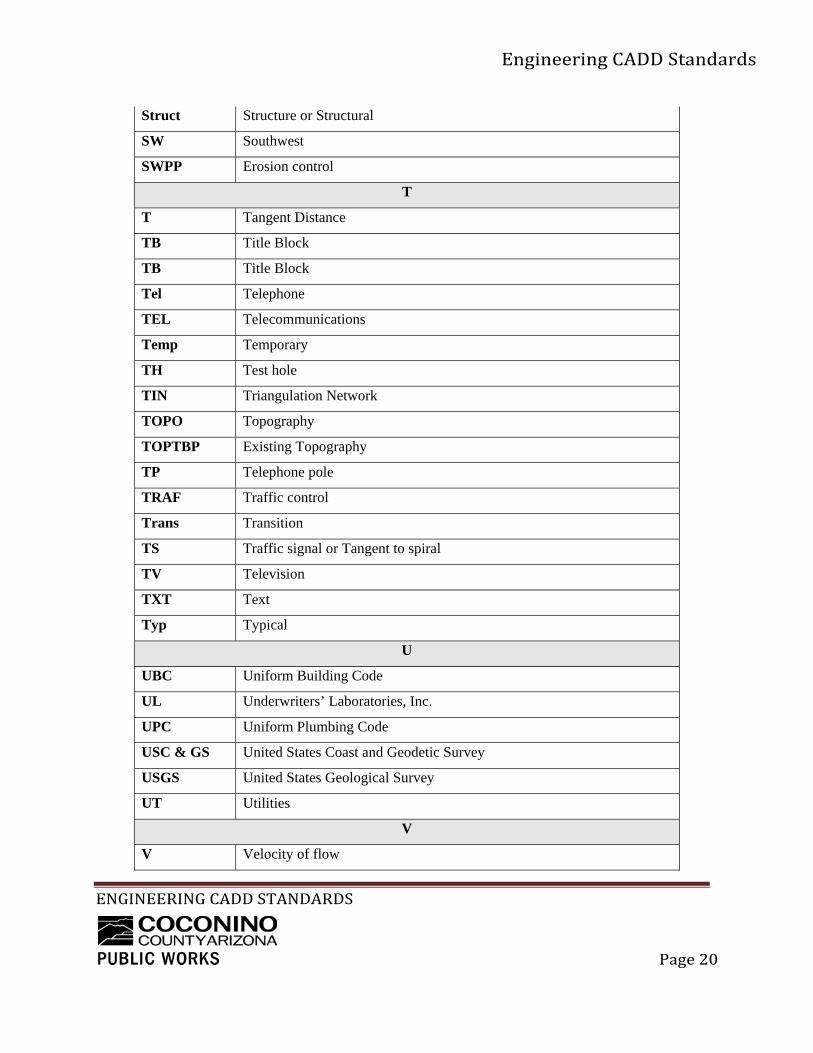
Struct Structure or Structural
SW Southwest
SWPP Erosion control
T
T Tangent Distance
TB Title Block
TB Title Block
Tel Telephone
TEL Telecommunications
Temp Temporary
TH Test hole
TIN Triangulation Network
TOPO Topography
TOPTBP Existing Topography
TP Telephone pole
TRAF Traffic control
Trans Transition
TS Traffic signal or Tangent to spiral
TV Television
TXT Text
Typ Typical
U
UBC Uniform Building Code
UL Underwriters’ Laboratories, Inc.
UPC Uniform Plumbing Code
USC & GS United States Coast and Geodetic Survey
USGS United States Geological Survey
UT Utilities
V
V Velocity of flow

EngineeringCADDStandards
ENGINEERINGCADDSTANDARDS
Page21
VC Vertical curve
VCP Vitrified clay pipe
VEG Vegetation
Vert Vertical
VP Viewport
W
W West or width
W Water
WALL Walls
WATER Water Utilities
WBP Proposed Water
WS Water & Sewer
Wt Weight
X Existing
Xref Xternal reference
Yd Yard
Symbols
‘ Feet or Minutes
“ Inches or Seconds
o Degrees
% Percent
# Number or Pound
@ At
/ Per
= Equals

EngineeringCADDStandards
ENGINEERINGCADDSTANDARDS
Page22
3.2 Linetypes
Fundamental line work in drawings consist of the following linetypes: Continuous, Centerlines, Hidden lines, Dashed lines, multiple Fence and utility lines and Phantom lines. There are any number of linetypes that may be incorporated into drawings.
LTSCALE is the AutoCAD line scale variable. In drawings with decimal units the Ltscale is normally set to the scale in which the drawing will be plotted, i.e 1’=40’Ltscale =40. In architectural drawings the LTSCALE is a multiplier used to scale up line definitions to fit the drawings plotted scale. For example, a drawing scale of 1/16"=1'-0" will have a LTSCALE of 192 for model space, 1/4” = 1’-0” a Ltscale of 48 and so forth. The zoom factor will then be 1/192 XP or 1/48XP in the paperspace viewports to achieve the appropriate scale and linetype. The LTSCALE is applied to the linetype definitions used in the drawing to provide proportional spacing for all linework.
PSLTSCALE is an AutoCAD system variable inRealease12 and above. AutoCAD drawings that use single viewports should set this variable to 0. Hence the linetype scale will be the same as the model ltscale. The PSLTSCALE shall be set to "1" on drawings with multiple view ports with multiple scales. This will enable all linetypes to be plotted according to the viewport scale factor (zoom XP). Drawings such as Detail Sheets may have numerous viewports of varying scales. All the linetypes will look the same when handled in this manner.
Plotted Line Weights
Using plot styles is recommended. Color-dependent plot style tables set style based on the color of the object. CTB files manages line weight through the graphic use of colors. Entity colors are mapped to logical pens, and each pen has an assigned value for thickness and tone. The designer is then capable of visualizing a plotted drawing by looking at the colors on the screen. Named plot styles (STB) can be assigned to an object independent of color. This allows objects to have a specific line weight and color by layer. The following is an example of a typical Color Table.

EngineeringCADDStandards
ENGINEERINGCADDSTANDARDS
Page23
AutoCAD Entity Color Table:
COLOR# COLOR WIDTH GENERAL USE
1 Red 0.1 mm Hatching, Center Lines
2 Yellow 0.3 mm Drawing Text and Fine Line Work
3 Green 0.45 mm
Drawing Medium Text and Fine Line Work
4 Cyan 0.6 mm Prop. Drainage or Secondary Lines
5 Blue 0.3 mm Ex. RJW or Prop. RJW
7 White 0.3 mm
Medium line work such as edge of pavement
8 Gray 0.2 mm Ex. Line work - Screened 50%
21 Beige 0.1 mm Ex. Major Contours
35 Brown 0.1 mm Ex. Minor Contours/Ex. Features
153 Light Blue
0.1 mm Profiles Grid
253 Light Gray HalfTone Color - Screened 30%
254 Lighter Gray
HalfTone Color/Solid Hatch - Screened 16%
3.3 Lettering, Linework and Data
Consistent text on drawing construction is very important and directly impacts our quality as a county employee. The plotted size of lettering is significant as this will facilitate readability by clients, and field personnel, as well as microfilming and other photographic reducing processes. Standard text height for design plan sets is 0.125" or 1/8". Text height of .25" (2 times standard text height) is to be used for detail, section title and match line call outs.