cds hydra-van 4.0 .45 c.1988-1991
TRANSCRIPT


Table of ContentsParts Order . . . . . . . . . . . . . . . . . . . . . . . . . . . . . . . . . . . . . . . . . . . . . 2How To Order . . . . . . . . . . . . . . . . . . . . . . . . . . . . 2HydraMaster Warranty Policy, . . . . . . . . . . . . . . . . . . . . . . . . . 3
Cleaning and Chemical Precautions Information. . . . 4Cleaning Stroke Procedure/Over-wetting . . . . . . . . . . . . . . . . . . . 4
Water Flow illustration . . . . . . . . . . . . . . . . . . . . . . . . . . . . . . . . . ...5Water and Chemical Flow Operation . . . . . 6Water So ftener . . . . . . . . . . . . . . . . . . . . . . . . . . 7Water Softener Hook-up illustration . . . . . . . . . . . . . . . . . . . . . 7
Chemical Proportioning andLevel Control illustration . . . . . . . . . . . . . . . . . . . . . . . . . . . . . . . 8
Chemical Tank Trouble Shooting , . . . . . . . . . . . . . . . . . . . . . . ...8.9
Freeze Protection . . . . . . . . . . . . . . . . . . . . . . . . . . . . . . . . . . . . . . ...10Freeze Guarding Solution System
andlncoming l-in elllustrations. . . . . . . . . . . . . . . . . . . . . . . . ...10Freeze Protection of Clutch Drive
with Pump-in System . . . . . . . . . . . . . . . . . . . . . . . . . . . . . . ..11
Bypass Valve illustration and Parts List. . . . . . . . . . . . . . . . . . . ...13Jet Assembly illustration . . . . . . . . . . . . . . . . . . . . . . . . . . . . . . . . ...13Wand Assembly illustration . . . . . . . . . . . . . . . . . . . . . . . . . . . . . ...13Valve Assembly illustration . . . . . . . . ., . . . . . . . . . . . . . . . . . . . ...14Stem Assembly illustration, . . . . . . . . . ., . . . . . . . . . . . . . . . . . . ...14
Vacuum System Information . . . . . . . . ., . . . . . . . . . . . . . . . . . . ...15Vacuum Flow illustration . . . . . . . . . . . . . . . . . . . . . . . . . . . . . . .15Vacuum Tank Filter Bags illustration . . . . . . . . . . . . . . . . . . . . . ...16Blower Lubricant illustration . . . . . . . . . . . . . . . . . . . . . . . . . . . . . ...16Lubrication . . . . . . . . . . . . . . . . . . . . . . . . . . . . . . . . . . . . . . . . . . . . ...17Filling Procedure . . . . . . . . . . . . . . . . . . . . . . . . . . . . . . . . . . . . . . ...17Vacuum blower Trouble Shooting Guide. . . . . . . . . . . . . . ...18. 19Vacuum Blower Warranty . . . . . . . . . . . , . . . . . . . . . . . . . . . . . . . ...20
Cat Pump Modei 290 . . . . . . . . . . . . . . . . . . . . . . . . . . . . . . . . . . . ...21Important Drive Information . . . . . . . .,, . . . . . . . . . . . . . . . . . . . ...22Pump-in System Flow illustration . . . . ., . . . . . . . . . . . . . . . . . . ...22Cat Pump Dimensions and Specifications . . . . . . . . . . . . . . . . ...23Piston Mode1290 Exploded View
and Parts List.............,.. . . . . . . . . . . . . . . . . . . . . ...24.25Cat Pump Trouble Shooting Guide . . . . . . . . . . . . . . . . . . . . ...26-29General Information for Cat Pump Repair . . . . . . . ..30Service Kits . . . . . . . . . . . . . . . . . . . . . . . . .,, . . . . . . . . . . . . . . . . ...31Pumping Section Cutaway .,...... . . . . . . . . . . . . . . . . . . . . . . ...31Servicing the Pumping Section . . . . . . . . . . . . . . . . . . . . . . . . . . ...32Servicing the Valve Assemblies . . . . . . . . . . . . . . . . . . . . . . . . . ...33Servicing Sleeves and Seals . . . . . . . . . . . . . . . . . . . . . . . . . . . . ...34Servicing Crankcase Section . . . . . . . . . . . . . . . . . . . . . . . . . . . . ...34Cat Pump Warranty . . . . . . . . . . . . . . . . . , . . . . . . . . . . . . . . . . . . ...35
Electric Diagram . . . . . . . . . . . . . . . . . . . . . . . . . . . . . . . . . . . . . . . ...36Electrical System . . . . . . . . . . . . . . . . . .,, . . . . . . . . . . . . . . . . . . ...37
Maintenance Procedures ...,.... . . . . . . . . . . . . . . . . . . . . . . . ...38Overall Careof Unit . . . . . . . . . . . . . . . . ,, . . . . . . . . . . . . . . . . . . ...38Maintenance Log . . . . . . . . . . . . . . . . . . . . . . . . . . . . . . . . . . . . . . ...39
Warranty Information . . . . . . . . . . . . . . . . . . . . . . . . . . . ., ..40Warranty Procedure . . . . . . . . . . . . . . .,, , . . . . . . . . . . . . . . . . . ...40HydraMaster Limited Warranty. . Inside back cover
Machine Serial No.@1988 HydraMaster Corp.
Printed in U.S.A.

PARTS WDERS HOW TO ORDERTo expedite your parts needs, please call your sales represen-tative, In most instances, he either stocks or has access to partsthrough a regional service center.
In the event parts are unavailable locally, contact the factory andcoordinate your needs. If this becomes necessary, always indicatethe method of shipment you desire, i.e. U.P.S., U.P.S. Blue Label,Air Freight, Air Express, etc.
REPLACEMENT PARTS
PART NO. DESCRIPTlON QTY.
000-078-015 Flow Meter Kit 1
000-078-019 Wand Valve Plunger Kit 1
000-078-034 Pressure Bypass Valve Kit 1
000-076-005 Spray Jet 8006 E 1
000-049-028 Recovery Tank Filter Bag 2
000-078-001 Cat 290 Short Cup Kit Standard 1
000-078-004 Cat 290 Hot CUD Kit (Ootional) 1
000-049-023 Screen Garden Hose 6
000-052-050 440 Male Quick Connect 1
000-052-051 440 Female Quick Connect 1
000-052-052 660 Male Quick Connect 1
000-052-053 660 Female Quick Connect 1
000-010-019 Belt, Pump Drive. AX-26 ,
To obtain a proper diagnosis of your malfunction, and to orderwarranty replacement parts, it is important that you proceed in thefollowing manner:
1.
2.
3,
4
Call HydraMaster Warranty/Service Dept. at (206) 775-7275.
Give the Warranty/Service Representative the followinginformation:
A. Name of your company and your acfcfress.B. Equipment Model (i.e. CDS).C. Date of purchase.D. Hours on the unit.E. Serial number of unit.F. Name of person authorized to order parts.G. Salesman unit purchased from.H. Description of malfunction.1. Pressure readings on high pressure gauge with wand turned
on and off.
If warranty replacement parts are needed, please specifymethod of shipment desired. NQTE All replacement parts aresent freight collect, via:
A. U.P.S.B. Air freightC. Air mailD. Air expressE. Auto Freight
Do not give malfunctioning parts to a HydraMaster Sales orService Representative. All parts must be returned directlyto HydraMaster, freight prepaid.20309 64th Ave. W., Lynnwood, WA 98036

HydraMaster WARRANTY POLICYEffective April 1, 1988
HydraMaster warranty covers only defective materials and/orworkmanship for the periods listed. Labor, and/or diagnosticreimbursement is specifically excluded.
Any questions you have regarding the warranty program should bedirected to the Warranty/Service Dept. Personnel at HydraMasterCorporation.
We shall always endeavor to be fair in our evaluation of yourwarranty claim, and shall provide you with a complete analysis ofour findings.
Written WARRANTY information is located inside the backcover of this owners manual.
HOURS:MONDAY THROUGH FRIDAY
8:OOam TO 6:OOpmPACIFIC STANDARD TIME
PST ROCK MT. CENTRAL EASTERN
TELEPHONE NUMBERSGENERALOFFICES:PARTSDEPTSERVICEIWARRANTkNEW EQUIPMENTSALES
AND MARKETING:
FAX: (206)
(206) 775-7272(206) 775-7276(206) 775-7275
1-600-426-1301
771-7156
NOTES

CLEANING AND CHEMICALPRECAUTIONS INFORMATIONYour mobile carpet cleaning plant has been engineered using thelatest and most sophisticated technology available, to produce thefinest carpet cleaning results possible. Despite this however, it re-mains only a tool’of the carpet cleaning trade, and it can produceonly as good a job as the person operating it.
There are no short cuts to good carpet cleaning, it requires time,cleaning knowledge and the use of good chemicals.
Manufacturer recommends the use of spotting agents, and trafficlane cleaners prior to the actual cleaning of carpeting, as required.
CAUTION when cleaning cut-pile acriian plush carpets: Using highheat setting may result in fiber damage.
The use of some chemicals through your mobile carpet cleaningplant can seriously damage the internal plumbing, high pressurepump and heater. (Chemical such as concentrated acids andsome paint oil and grease removers w/high concentration ofsolvents.)
Manufacturer recommends only the use of chemicals containingrust and corrosion inhibitors and water softening agents to preventchemical build-up.
NOTE: At no time should a chemical solution with pH of less than 7or higher than 10 be used in the unit.
pH CHAFIT
12345678910 1112 13 14I
+ ACID — NEUTRAL ‘ALKALINE ~
CLEANING STROKEPROCEDURE/OVER-WETTINGPurpose:To eliminate excess moisture remalnlng m the carpet fiber and thesawtooth appearance which results from diagonal movement ofthe cleaning tool on all types of carpet.
Procedure:Always move the cleaning tool in smooth forward and backwardstrokes. Apply sfight pressure to the forward stroke while the solu-tion is injected mto the carpet. When extracting (drying), apply firmpressure on the forward stroke to ensure a positive “lock” for thevacuum and minimize the “hopping” effect resulting on unsmoothcarpet. During the forward and reverse strokes. movement to theright or left should only be accomplished at the extreme rear of thestroke. Overlapping is also important to ensure even application ofsolution to prevent saturation when cleaning wand is stoppedtwice at the same point at the rear of the cleaning stroke.
Failure to adopt this procedure can result in increased chance of“clean streaks”, fiber shrinkage, brown out, and longer dryingperiods.

INCORRECT METHOD CORRECT METHOD
OverlaD Between Strokes\/
‘Cleaning Tooly/~*u,,
First Secondu u Cleaning Cleaning
Stroke Stroke
Over-Wett inaOver-wetting is a%noying to all concerned and sometimes leaves abad impression of the cleaning process used.
These are several areas that will cause over-wetting:
1. Too few vacuum strokes or improper saw tooth vacuum strokesas shown above.
2. Obstructed, kinked or cut hoses.
3. Vacuum tank drain valve left partially open.
4. Clogged vacuum blower filter or vacuum tank lid not sealingproperly.
5. Cleaning a heavily foam-saturated carpet without defoamer.(We recommend crystal type.)
WATER FLOW
A. Pressure Gauge J. Pump IntakeB. Hot Water Shut-Off Valve Control K. Heat ExchangersC. Bypass Valve L. Radiator Water (In)D. High Pressure Solution Outlet M. Pump OutputE. Incoming Water N. Bypass ReturnF. Drain O. Chemical Flow MeterG. Radiator Water (Out) P. Chemical JugH. Proportioner Q. High Pressure Pumpi. Chemical Mix Tank R. Pump Inlet Filter
(not shown)

WATER ANDOPERATION
CHEMICAL FLOW
This system has been designed to be the most simple and trouble-free ever.
The incoming water flows directly to the mix tank. Water will nowflow through a proportioning valve which will simultaneously mixthe chemical to achieve your desired solution. The mix tank isequipped with 2 different float valves, one of which responds to thewater level of the tank and will maintain the proper volume of solu-tion to be reserved for the cat pump. The secondary float valve is asafety valve that is designed to protect your system from sudden orunexpected loss of water supply. If, for example, the water sourceat the house was turned off, the water level of the mix tankwould drop, activating the secondary valve which automaticallydisengages the electric pump clutch.
In conjunction with the incoming flow, the chemical ratio may beobtained by an adjustment of the chemical flow meter during the fillcycle of the mix tank. The chemical will flow from the chemical jugto the chemical flow meter, then to the proportioner where it isdistributed into the mix tank at your desired proportion. This lineshould be flushed with vinegar weekly to prevent abnormalchemical build-up. This may be done by removing the clear plastichose from the chemical jug and inserting it into a one quart con-tainer of vinegar. This should be done with the chemical flow metersetting on 10 GPH with heater “off”. Simply spray the wand for theduration of the vinegar in the one quart container, then repeat theprocess with clear water to void all lines of vinegar.
NOTE: With this unique chemical system, your chemical flow isproportioned to the filling cycles of the mix tank, not the directspraying of the wand. Therefore, it is possible that as your wand isspraying, you may have no chemical flow. Also, the converse istrue in that you may not be spraying your wand but, if the mix tank
is in a filling cycle your chemical flow meter may read your desiredflow.
This chemical system will mix a 1 to 30 ratio when flow meter is setat 5 GPH. Most chemical suppliers will recommend a 1 to f5 ratiotherefore you can either set the flow meter at 10 GPH, giving you a1 to 15 ratio of chemical to cleaning water, or double the recom-mended strength of chemical in the 5 gallon jug and set the flowmeter at 5 GPH, thereby attaining a 1 to 15 ratio, (It is recom-mended that you set the flow meter at 10 GPH for overall bestresults.)
The water will now be siphoned from the bottom of the mix tank tothe Cat Pump, If the wand is not spraying, the water will bypassfrom the bottom of the brass pressure relief valve to the mix tank.

WATER SOFTENERMany areas of the country have an excess of minerals in the waterwhich results in what is commonly called “hard water”. Theseminerals tend to adhere to the insides of heater coils and otherparts of the machines causing damage and a loss of cleaningeffectiveness.
Reports from several of our machine users commending theresults of the use of water softeners in conjunction with theirmachines prompts us to recommend the procedure to everyone ina “hard water” area.
The relatively low cost of a water softener service is more thanmade up for in the increased life of machine parts and continuedcleaning efficiency. The water softener will also increase the effec-tiveness of the cleaning chemical being used, therefore, lesschemical will be needed.
Contact a water softener distributor in your area for information onthe rental of a simple water treatment unit to carry in your truck. Besure to change the water softener in accordance with the capabili-ty of the softener. Example: If the softener will treat 900 gallons ofwater and the machines uses an average of 30 gallons per hour ofuse on an average of 5 hours a day would be 150 gallons a daywould be treated. Five days would equal 750 gallons of water,therefore, the softener would be changed every 6 working days formaximum softening.
WATER SOFTENER HOOK-UP
Water Softener

CHEMICAL PROPORTIONING ANDLEVEL CONTROL
Valve Body Cap
/
Proportioning Valve Repair Kit000078
s/
Ball Nut Extension
~ W/Set Screw Bracket
—.25-L‘Q
\/?+ -a—-=E57r7jValve Plunger
—$$’ —Adjust ment I IFloatAssm.
u @!AiOutletTube tw
Foot Valve andScreen
—ProportioningVenturi
——Main ValveDiaphragm
Underwate(Feed
CHEMICAL TANK TROUBLESHOOTINGPROBLEM: No or Low Chemical Flow
Solution
Check that hoses in the tank are secured, Check that thehose from the top of the flow meter to the side of the mixtank is secured with no kinks. Check the hose from thebottom of the flow meter to the chemical jug for kinks orcracks.
Check the foot valve and screen on the end of the hosewhich goes into the mix tank. To check this screen forproper function, remove it from the plastic hose. Youshould be able to suck through the hose barb end, but youshould not be able to blow through the hose barb end, (Ifyou can not suck through it then rinse it out with vinegar, )When screen is removed the chemical fill hose should belifted into a vertical position so the ball in the foot valvewill seat by gravity. (This is only a temporary fix for lowwater pressure areas. )
Check flow meter for float obstruction.
Check to insure that the adjusting screw on proportioningventuri is backed out. - “
Is
Is
proportioning venturi closed? Soak in warm water orvinegar solution. I
incoming water pressure less than 20 PSI?
Cracked or defective chemical flow meter?
NOTE: If you are in a low water pressure area and find thatthe volume of water entering the mix tank is not enough toallow your venturi to siphon chemical, unscrew the springfrom the foot valve screen and remove the spring.
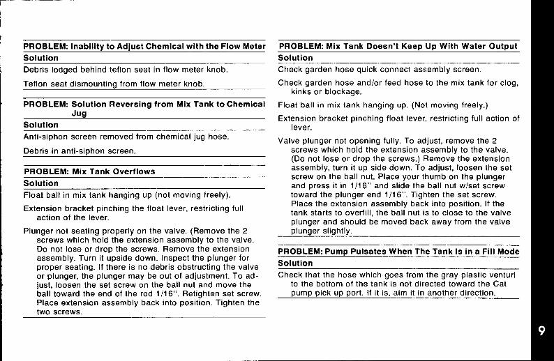
PROBLEM: Inabilitv to Adiust Chemical with the Flow Meter. ,Solution
Debris lodged behind teflon seat in flow meter knob.
Teflon seat dismounting from flow meter knob,
PROBLEM: Solution Reversing from Mix Tank to ChemicalJug
Solution
Anti-siphon screen removed from chemical jug hose
Debris in anti-siDhon screen.
PROBLEM: Mix Tank Overflows
Solution
Float ball in mix tank hanging up (not moving freely).
Extension bracket pinching the float lever, restricting fullaction of the lever.
Plunger not seating properly on the valve. (Remove the 2screws which hold the extension assembly to the valve.Do not lose or drop the screws. Remove the extensionassembly. Turn it upside down. Inspect the plunger forproper seating. If there is no debris obstructing the valveor plunger, the plunger may be out of adjustment. To ad-just, loosen the set screw on the ball nut and move theball toward the end of the rod 1/1 6“. Retighten set screw.Place extension assembly back into position. Tighten thetwo screws.
PROBLEM: Mix Tank Doesn’t KeeD UD With Water Out~ut
Solution
Check garden hose quick connect assembly screen.
Check garden hose and/or feed hose to the mix tank for clog,kinks or blockage.
Float ball in mix tank hanging up. (Not moving freely.)
Extension bracket pinching float lever, restricting full action oflever.
Valve plunger not opening fully. To adjust, remove the 2screws which hold the extension assembly to the valve.(Do not lose or drop the screws.) Remove the extensionassembly, turn it up side down. To adjust, loosen the setscrew on the ball nut. Place your thumb on the plungerand press it in 1/1 6“ and slide the ball nut w/set screwtoward the plunger end 1/16”. Tighten the set screw.Place the extension assembly back into position. If thetank starts to overfill, the ball nut is to close to the valveplunger and should be moved back away from the valveplunaer sii~htlv.
PROBLEM: Pump Pulsates When The Tank Is in a Fill Mode
Solution
Check that the hose which goes from the gray plastic venturito the bottom of the tank is not directed toward the Catpump pick up port. If it is, aim it in another direction.

FREEZE GUARDING SOLUTION SY’STZMAny freezing of this machine is not covered by warranty and dur-ing the colder months of operation, careful protection should be ofutmost concern.
THE FOLLOWING PRECAUTIONS ARE RECOMMENDED:
1, Run machine before leaving for the first job to insure nothinghas frozen the night before, including hoses and wand.
2. Insulate the garden hose from the cold ground by running itthrough an extra 11/2inch vacuum hose.
3. Leave truck doors closed until time cleaning begins, then openslightly.
4. In colder climates, insulating the truck walls and floor boards willhelp protect the unit.
5. Don’t procrastinate during the cleaning operation or the hotwater solution line will also freeze on the ground. The solutionline should be insulated in extremely cold climates.
6. Whenever possible, the truck should be stored in a heatedgarage at night or over the weekend. If not possible, place a1500 watt electric heater inside the truck, aimed directlyat the machine. Never use a propane heater - it causes ex-cessive moisture on the truck ceiling and the possibility of itgoing out is higher. If the machine and truck are left outside witha heater, you should first drain all possible water from themachine cleaning tools and hoses. (They freeze also, )
TO DRAIN THE MACHINE, FOLLOW THESE STEPS:
A. Before shutting off the machine, remove the chemical line fromthe chemical jug and place in a mixture of 50/50 anti-freeze andwater. With the cleaning tool on, allow mixture to fill chemicalsystem back to the chemical mix tank.
B. Open the mix tank drain valve and allow the water to drainthoroughly from the mix tank.
%
\
k.@iail
@b>
/To Vac Tank ,.
.:.
\.,
\\
Connect to vacuum
Connect freezelank and run the
guard qu(ckvacuum unt,l all
coupler to onemomture IS removedNOTE Loosen
of the outgo, ngbypass valve be!Ofe
soluhon malequ,ck connects.
running vacuum.
FREEZE GUARDINGINCOMING LINE
To Vac Tank& Connecl garden hose
,nlel connector m the
/Shale the vacuum hose all the way over Ihe mlelconnector and run the vacuum unhi all themo)slure m removed.
C, Remember to close the drain valve prior to next operation ofyour CDS unit.
Check ENGINE Antifreeze regularly,
BE SURE IT’S PROTECTED!Freezing will cause GRIEF, MONEY and DOWN-TIME. Don’tmess with mother nature!

FREEZEPROTECTION OF CLUTCHDRIVE WITH PUMP-IN SYSTEM
.
1.
2.
3.
4.
5.
Start with machine in cleaning mode.
Drain chemical mix tank. (fig. 1)
While chemical mix tank is drainina: Insert chemical feed lineinto antifreeze premix jug and allo-w meter to fill with premixanti freeze for 10 seconds, Close chemical flow meter whenprotected. (fig. 2)
Shut machine down. Connect short hose to high pressurequick connector and drain heat exchanger of cleaning water,(fig. 3)
Remove pump-in system hose from water storage tank and in-sert it into antifreeze premix jug. (fig. 4)
6. Close chemical mix tank drain valve and allow DumD-in svstem
7
8.
9.
to refill mix tank with antifreeze premix solution. (~g. 5)’
Start unit with cleaning wand and hoses connected and sprayinto a bucket for 20 seconds to allow the antifreeze to protectthe high pressure gauge and system lines. After running thewand spray for 20 seconds, shut wand off and let it run for10 seconds to allow the bypass system to be protected. (fig. 6)
Turn off cleaning system Master Power Switch. You may wantto leave the pump-in hose out of the tank so it won’t freeze tothe residual water in the tank. The next day, refill the tank andreplace the hose. If layer of ice, the hose will sit on top of it andgain proper suction.
Reconnect pump-in hose to water storage tank.(continued next page)
Fig. 1 Fig. 2 Fig. 3 Fig. 4 (continued next page)

1(Y.
11.
12.
FWacebucket under drain hose of chemical mix tank and opendrain valve again to reclaim antifreeze premix. When tank isempty, reconnect short hose to high pressure quick connectorand drain heat exchanger into bucket. (fig. 7)
Shut off valves and pour all reclaimed antifreeze from bucketback into the 5 gallon antifreeze premix jug so it can be usedagain. (fig. 8)
Before cleaning the next day run unit for 3 minutes to void allexcess antifreeze from the system.
Fig. 5 Fig. 8

BYPASS VALVE 8
169-101 Q?7
Bypass Valve Parts ListREF. NO. PART NO. DESCRIPTION QTY.
3. 000-105-101 Thrust Plate, BypassValve 1
4. 000-105-102 Piston Plate, BypassValve 1
5. 000-078-101 Kit, Seal for BypassValve 1
7. 000-148-004 Seat & O-Ring, BypassValve 1
8. 000-097-005 O-Ring, Bvpass ValveFitting- -‘ 1
JET ASSEMBLY Body\, *-
P
@
Brass Cap
/&”&<800-st~’’’”e’
WAND ASSEMBLY
See “Valve Assembly”

VALVE ASSEMBLY
II
Connect
STEM ASSEMBLY
!w +.-.-Retainer
Keeper Ring————+~
@—(l-Ring
i
Plunger—
I1
@— Cl-Ring

VACUUM SYSTEM INFORMATIONThe vacuum blower incorporated in this machine is a positivedisplacement lobe type, manufactured by Cooper Industries. Theperformance and life of this unit is greatly dependent on the careand proper maintenance it receives.1Because of the close tolerances between the lobes and housing ofthe vacuum blower, solid objects entering the inlet will damage theinternal lobes, gears and bearing or direct drive coupler.
tTo prevent this, a stainless steel filter screen has been placed atthe vacuum inlet inside the vacuum recovery tank. This stainlesssteel screen is finger tight and should be removed weekly forcleaning.
Caution should be used when machine is being run for test pur-pose and the vacuum inlet on top of machine is open.
To protect the vacuum blower from overloading and damagingitself, there is a vacuum relief system installed on the vac tank.When the vacuum tank inlet is completely sealed off, a maximumof 12 HG will be attained. A blower lube port is located above thevacuum gauge; at the end of each day, LPS 1 or WD-40 is sprayedin before shutting down the machine. See blower lubricationillustration. If you fail to lubricate the vacuum blower daily, rustdeposits and moisture will decrease the life of the vacuum blower.
Caution: Foam passing through the blower could lead to seriousproblems, therefore, it is important to keep the vacuum tank foamfree.
VACUUM FLOW
Filter Bag/ Recovery Tank
fl>C- G-E-P lbG-
Vacuum
%
‘i-(Hose ToCleaningWand
ExhaustVacuum Blower Silencer

VACUUM TANK FILTERBAGSHydraMaster filter bags are designed to trap most of the lint, sandand dirt that would normally collect at the bottom of your vacuumtank. The use of these bags, if emptied at the end of each job, willeliminate the build-up of much of the debris in the tank and avoid amess. The drawstring top of these bags is designed to be tied tothe incoming dirty water inlet in the vacuum tank.
To re-order bags use part number 049-029.
VACUUM TANK FILTER BAGS
ty Water
Tank
“Filter Bag
BLOWER LUBRICANT
Spray lubricant into blower lube port for 3 to 5seconds, then immediately shut off machine,
Use only LPS 1 or WD-40 moisture displacinglubricants.

LUBRICA~ONAt the gear end the timing gear teeth are lubricated by beingpartialiy submerged. The gear teeth serve as oil slingers for
aear end bearings. At the drive end the bearings are grease~ubricated.
FILLING PROCEDURERemove square head vented oil fill plug (A) on gear end.Remove oil level plug (B) located in the head plate. Fill gearcase until oil drips out of the oil level hole (B).
Use lubricants as listed.
Add fresh oil as required to maintain proper level. The oilshould be drained, flushed and replaced every 1500 hours ormore frequently if inspection so indicates. The oil drain plug isat (C).
NOTE: Older units may have the oil fill level and drain holeslocated in the cast iron gear case instead of in the head plate.
Bearings on drive end of blower require grease I,ubricationevery 100 hours of operation. Bearings which require greaselubrication will have a grease fitting (D) at each bearing. Whenregressing, the old grease will be forced out of the vents duringoDeration. To prevent damage to seals, these vents must bek~pt open at all times,
e. . SAE20 100------
0 3P wto 215”F
5“cCAF All
J 38”to13200
1 .,. .- .-
owr27~F SAE50 250
&“In applications with extreme variations, inambient temperature a 20W SOW multtple
I Service------- 1 BEARINGSeverv 500 hours of operation
~\ (-,ryto 12mc)

lHkCIJUMBLOWER TROUBLESHOOTING GUIDEPRCM$LEM: Loss of Vacuum
Cause Solution
Collapsed vacuum hose between blower and vacuum tank. Remove and replace hose. NOTE: A special reinforced hoseis required for replacement.
Clogged stainless steel filter. Remove and clean or replace stainless steel filter.
Defective vacuum tank seal. Remove and replace vacuum tank seal,
Defective or ‘open’ vacuum tank dump valve. Close valve.
Replace valve.
Fractured weld on vacuum tank. Re-weld as required or replace tank.
Collapsed or kinked vacuum hose. Reshape hose if possible and/or eliminate kinks.
Plugged vacuum hose. Remove obstruction by reversing the vacuum hose.
Restriction in cleaning tool. Remove obstruction.
Worn end plates or lobes in vacuum blower. Replace worn components. NCITE: Must be accomplished bya qualified technician.
Loose drive shaft between clutch and blower. The set screws may come loose causing blower to stand stillwhile engine may be turning properly. NCJTE: Unless theblower is seized or making a knocking noise, your vacuumloss is not caused by a bad blower.
PROBLEM: Blower is Seized
Cause Solution
Rust. Spray rust dissolving lubricant onto lobes to emulsify rust andattempt to rotate vacuum lobes.
Foreign matter. Disassemble and remove foreign matter and repair asrequired. NOTE: Disassembly must be accomplished byqualified technician.
NOTE: The above mentioned, rust, foreign matter and seizing are often caused from foam traveling through the Mower.

PROBLEM: Noise in Vacuum Blower
Cause Solution
Loose Direct Drive Coupler. Examine universal shaft for defects and retighten lock bolts.
Replace universal shaft.
Worn Gears. Remove and replace gears. NOTE: Replacement of gearsmust be accomplished by a qualified technician.
Timing of vacuum blower has been changed due to worncomponents. Replacement of components must beaccomplished by a qualified technican.
Lack of Lubrication. NOTE: Permanent damaae mav have Lubricate as s~ecified. See index.-.resulted from lack of lubrication.
Worn bearings. Remove and replace bearings as required. Must beaccomplished by qualifie~ technician.
Debris and/or foreign material build-up. NOTE: A stainless Disassemble vacuum blower and remove foreign material.steel filter is provided at vacuum inlet located in vacuum NOTE: Disassembly should be accomplished by qualifiedtank. technician only. Replacement of worn parts is recom-
mended if this procedure is necessary.
Loose or missing mounting bolts. Tighten or reinstall mounting bolts.

VACUUM BLOWER WARRANTY
1, All Sutorbilt California Series ‘F’ blowers are covered by this warranty.
2. Warranty period is 24 months from date of shipment, or 18 months from date of installation, whichever occurs first.
3. Sutorbilt will replace or repair any unit covered by this warranty without regard for the cause of failure.
4. Customers claiming relief under this warranty shall issue a Purchase Order to Sutorbilt for a replacement unit.
5. Customer must obtain a Return Goods Authorization number from the factory and return blower prepaid to an AuthorizedFactory Repair Center, as directed.
6. On receipt of the blower a credit memo will be issued to offset the P.O. issued per (4) above.
7. Replacement unit will be shipped to customer at Sutorbilt’s expense to any destination in the US or Canada.
8. SUTORBILT reserves the right to withdraw the Uncontested Warranty where evidence indicates application outside themanufacturer’s stated performance area, or where there is evidence of abuse.
CONTACT SUTORBILT FOR THE LOCATION OF THEFACTORY AUTHORIZED SERVICE CENTER NEAREST YOU
IAcooPE-1 sw Bwnwm
.... .,---,
1 -— SUTORBILT/lNDUSTFilAL MACHINERY2966 E. Victoria Street
“ ‘-ADD” mCompton, CA 90224(213) 639-7600Telex: 244337SUTFAX: (21 3) 639-7632

CAT PUMPS Model 290
OPERATING INSTRUCTIONCAUTION: CAT PUMPS are positive displacement pumps.Therefore, a properly designed pressure relief mechanism MUSTbe installed in the discharge piping. Failure to install such reliefmechanism could result in personal injury or damage to the pumpor system. Cat Pumps Corporation does not assume any liability orresponsibility for the operation of a customer’s high pressuresystem.
I 1
I Products described hereon are covered by one or more ofthe followina U.S. Datents: 3558244, 3652188, 3809508, I3920356, a;d 3930756
B
● CAT PUMPS — A.G. 9Loretohoehe 5
CH.6300 ZUG, SwitzerlandPhone (42) 21.21-40 — Telex S45 100 cpag ch
CORPORATION● CAT PUMPS DEUTSCHLAND GmbH ●
P.O. BOX SS5 MINNEAPOLIS, MN 5544oRestocker Strasse 9
Phone (612) 780.5440 — Telex 29027662C0 Wlesbaden.Slerstadt, West Germany
Phone 0012.56 (W 0112 — Telex 412$713
● N.V. CAT PUMPS INTERNATIONAL S.A. ● ● CAT PUMPS (U. K.) LTO, ●
Harmonlestraat 29 27 Stat Ion I ndustrlal Estate, FleetB 2000 Antwerp, SelEium
Phone (03) 237.72.24 — Telex 33947Hampshire GU1380Y,England
Phone Fleet 22031 — Telex 6SSS98

WIPORTANT DRIVE INFORMATIONPump speed and pump output in gallons per minute as tabulated isbased upon a 1725 RPM drive motor. Select motor pulley size andprovide GPM of the approximate pump output desired.
Pump RPM and GPM output are approximate values due to varia-tions in pulleys, belts and motors between manufacturers and a* 5% pump output tolerance.
Horsepower figures shown are brake horsepower figures. For gasengine requirements, follow engine manufacturer’s recommenda-tions. In general, use a gas engine with approximately double toelectric motor horsepower.
I HORSEPOWER REQUIREMENTS I
PRESSURE MOTOR PULLEY SIZE
Flow Psl F@ Psl Using 1725 RPM Motor &
800 1000 1200 Std. Pump Pulley O.D.
GPM L/M BAR BAR OA!lI
RPMI
?uiley55 70 85 O.D. I
3.5 13 1.9 2,4 2.9 1200 3.53.0 11 1.7 2.1 2.5 1029 3.02.5 9 1.4 1.7 2.1 858 2.5
I DETERMINING Rated G.P.M. = “Desired” G.P. M.
THE PUMP R.P.M. Rated R.P. M. “Desired” R.P. M. IDETERMINING GPM X PSI = Electric Brake
THE REQUIRED H.P. 1460 H.P. Required IDETERMINING Motor Pulley 0.0. = Pump Pulley O.D.
MOTOR PULLEY SIZE Pump R.P. M. Motor R.P. M.
Note Consul! engine manufacturer when using gas or dresel e“gtne
Incoming WaterConnection

I
CAT PUMP DIMENSIONS2.28
- (58)-
1
3/8” NM OUTL=
\c
d.d1.0(33}
p%ii4,.i7,,
SPECIFICATIONSU.S. Measure
Volume . . . . ..5 G. . . . . . . . . . ..3.5 G.P.M.Discharge Pressure . . . . . ..1200 P.S.I.Max. Inlet Pressure . . ...-8.5 to 40 P.S.I.
RPM . . . . . . . . . . . . . . . . . . . . . ..12 OORPM
Bore . . . . . . . . . . . . . . . . . . . . . . . . .. O.787°Stroke . .. O. . . . . . . . . . . . . . . . . . .. O.472°Crankcase Capacity . . . . . . . . . . ..1 OOZ.Maximum Fluid Temperature. 160”F
inlet Ports (l). ... , . . . . . . . . . ..l/2’’NPT
Discharge Ports (2) . . . . . .3/8” NPT
Pulley Mounting . . . . . . . . . .Either side
Shaft Diameter . . . . . . . . . . ...0.650”
Waight, . . . . . . . . . . . . . . . . . . . ..l2.l Ibs.
Dimensions. ., ..10.77” x 9.06” x 5.14”
Metric Measure13 L/M
85 BAR-0.6 to + 2.8 BAR
1200 RPM20 mm12mm
.3 L71°C
1/2” NPT
3/8” NPT
Either side
16.5 mm
5.5 kg273,5 x230x 130.5fnm

PISTON MODEL 290 Exploded View

PARTS LIST Model 290ITEM PART NO. DESCRIPTION QTY.
1 20285 O-Ring (Buns-N) 12 44274 Crankcase 13 85680 Stud (M8 X 82) 24 44377 O-Ring, Oil Filler Cap 15 44374 Oil Filler Cap 18 43340 O-Ring, Crankcase Cover 19 43339 Crankcase Cover 110 43987 Bubble Oil Gauge 111 23170 O-Ring, Drain Plug 112 25625 Drain Plug 115 92520 Sems Comb Head Screw
(M6 x 20) 616 43804 Crankshaft 117 14487 Rearing 216 24159 Oil Seal (Buns-N) 2
19 26536 O-Ring, Oil Seal Case 2
20 27950 Oil Seal Case 221 92519 Sems Comb, Head Screw
(M6 X 16) 8
23 101799 Connecting Rod 3
24 101800 Piston Rod 3
25 16948 Piston Pin 3
26 20017 Seal Washer 3
27 25301 Oil Seal 3
28 25327 Barrier Slinger 3
29 25392 O-Ring, Sleeve 3
26771 O-Ring, Sleeve (Viton) 3
30 29003 Back-Up Ring, Sleeve (Teflon) 3
31 29614 Sleeve (29743 Unchromed) 3
32 26854 Seal Washer 3
33 28597 Seal Retainer 3
34 25128 Inlet Manifold 1
25635 Inlet Manifold-Stainless Steel 1
ITEM PART NO. DESCRIPTION QTY.
35 30315 Prrrrrm-A-Lube Seal 3
30325 Prrrrrm-A-Lube Seal (Viton) 3
38 27004 Inlet Valve 3
39 30543 Bat-Cup Piston 3
40 30544 Bat-Cup Ring (Teflon) 3
41 43172 Cup (Viton) 3
43474 Bat-Cup Assembly 3
42 27963 Piston Spacer 3
43 27002 Piston Retainer 3
44 27006 Conical Washer-SS (M6) 3
45 27000 Nut-SS (M6) 3
46 14158 Cotterpin 3
47 101802 Cylinder (43834 Unch) 34R 2!3172 O-Rino. Cvlinder [Buns-N) 6
58 25130
Electric Clutch Assembly59 152-00560 077-00561 036-00562 143-084
63 174-0046A 174-018
52 43360 Valve Spring 3
53 43723 Valve 3
54 43434 Discharge Valve Seat 3
56 81109 Hex Nut (M6) 2
57 101804 Hex Flange Nut (M8) 2
)r 1Shaft Protectc
Tapered Sleeve 1
Key, Electric Clutch 1
6“ Electric Clutch 1
6-30 mm Socket Head Screw 1
Flat Washer (5/1 6 US) 1
Lock Washer (5/1 6 US) 1

CAT PUMP TROUBLESHOOTING GUIDEPROBLEM: Pulsation
Cause Solution
Debris in discharge valves of pump. Clean or replace discharge valves.
PROBLEM: Low Pressure
Cause Solution
Worn nozzle. Replace nozzle, of proper size.
Belt Slippage. Tighten or replace use correct belt.
Air leak in inlet plumbing. Disassemble, reseal, and reassemble.
Pressure gauge inoperative or not registering accurately. Check with new gauge; replace worn or damaged gauge,P.N. 06090
Relief valve stuck, partially plugged or improperly adjusted; Clean, and adjust relief valve; check for worn and dtrty valvevalve seat worn. seats. Kit available.
Inlet suction strainer clogged or improper size. Clean. Use adequate size. Check more frequently.
Worn piston assembly. Abrasives in pumped fluid or severe Install proper filter. Suction at inlet manifold must be limitedcavitation. Inadequate water supply, to lifting less than 20 feet of water or -8.5 PSI vacuum.
Fouled or dirty inlet or discharge valves. Clean inlet and discharge valve assemblies.
Worn inlet or discharge valves. Replace worn valves, valve seats.
Leaky discharge hose. Replace discharge hose.
PROHLEM: Pumps runs extremely rough, pressure very low
Cause Solution
Restricted inlet or air entering the inlet plumbing. Proper size inlet plumbing; check for air tight seal.
Inlet restrictions and/or air leaks. Damaged cup or stuck inlet Replace worn cup or cups, clean out foreign material, replaceor discharge valve. worn valves.
Worn inlet manifold seals. Replace worn seals.

PROBLEM: Cylinder O-rings blown next to discharge manifold
Cause Solution
Pressures in excess of rated PSI. Check for plugged nozzle, closed valves or improperlyadjusted by-pass valve.
Warped manifold. Replace manifold.
PROBLEM: Leakage at the cylinder O-rings at the discharge manifold and black, powdery substance in the area of theO-rings
Cause Solution
Loose cylinders. Cylinder motion caused by improper Remove spacer shims on manifold studs. Do not remove tooshimming of the discharge manifold. many shims or the ears of the manifold will be bowed
when the manifold is retightened, causing looseness inthe center cvlinder.
PROBLEM: Water leakage from under the inlet manifold
Cause Solution
Worn inlet manifold seals. Leaking sleeve O-ring. Install seals. If piston rod sleeves are scored, replace sleevesand sleeve O-rings.
PROBLEM: Oil leak between crankcasa and pumping section
Cause Solution
Worn crankcase piston rod seals. Replace crankcase piston rod seals.
Excess oil from wicks. Reduce quantity of oil per oiling.
PROBLEM: Oil leaking in the area of Crankshaft
Cause Solution
Worn crankshaft seal or improperly installed oil seal retainer Remove oil seal retainer and replace damaged gasket and/orpacking. seals.
(contmed next page)

CAT PIMP TROUBLESHOOTING GUIDE (continued)
=O13LEM: Oil leaking in the area of Crankshaft
Cause Solution
Bad bearing. Replace bearing.
PROBLEM: Excessive play in the end of the crankshaft pulley
Cause Solution
Worn main ball bearing from excessive tension on drive belt. Replace ball bearing, Properly tension belt.
PROBLEM: Water in crankcase
Cause Solution
May be caused by humid air condensing into water inside the Change oil at 3 month or 500 hour intervals using Cat Pumpcrankcase. Crankcase Oil (other approved oil every month or 200
hours) P.N.: 06100.
Leakage of manifold inlet seals and{or piston rod sleeve Replace seals, sleeve and O-rings.O-ring.
PROBLEM: Oil leaking from underside of crankcase
Cause Solution
Worn crankcase piston rod seals. Replace seals, sleeve and O-rings.
PROBLEM: Oil leaking at the rear portion of the crankcase
Cause Solution
Damaged or improperly installed oil gauge or crankcase rear Replace oil gauge or cover O-ring, and drain plug O-ring,
cover O-ring, and drain plug O-ring.
PROBLEM: Oil leakage from drain plug
Cause Solution
Loose drain plug or worn drain plug O-ring Tighten drain plug or replace O-ring.

PROBLEM: Loud knocking noise in pump
Cause Solution
Pulley loose on crankshaft. Check key and tighten set screw.
Broken or worn bearing. Replace bearings.
PROBLEM: Frequent or premature failure of the inlet manifold seals
Cause Solution
Scored rods or sleeves. Replace rods and sleeves.
Over pressure to inlet manifold. Reduce inlet pressure per instructions.
PROBLEM: Short cup life
Cauae Solution
Damaged or worn chrome plating of the cylinders. Replace cylinders.
Abrasive material in the fluid being pumped. Install proper filtration on pump inlet plumbing.
Excessive pressure and/or temperature of fluid being pumped. Check pressures and fluid inlet temperature; be sure theyare within SDeCified ranae.
Over pressure of pumps. Reduce pressure.
Running Pump dry. Do not run pump without water.
Front edge of piston sharp. Replace with new piston.
Chrome plating of cylinders damaged causing excessive wear Install new cups and cylinders. Pump only fluid compatibleof cups. May be caused by pumping acid solution. with chrome.
PROBLEM: Strong surging at the inlet and low pressure on the discharge side
Cause Solution
Foreign particles in the inlet or discharge valve or worn inlet Check for smooth lap surfaces on inlet and discharge valveand/or discharge valves. seats. Discharge valve seats and inlet valve seats may be
laDDed on a verv fine oil stone; damaged CUPSanddischarge valves cannot be lapped bit must be replaced.

GENERAL INFORMATION FORCAT PUMP REPAIRAs you remove your discharge manifold, there is a set of 3 checkvalves (which usually fall out during dis-assembly). If the surfacesof these check valves are dirty, or show signs of chemical build-up,it is probable that they would remain open causing pressure lossor pulsation. Upon inspecting the valves, make sure that the teflonbuttons in the valve spring retainers are still intact. Also examinethe discharge manifold. Look for problems such as cracks,chemical buildup or warpage due to freezing. If this dischargemanifold is warped, it will cause the check valves to stick and willresult in loss of pressure.
The Cat pump cups are often the source of pressure loss. Upon in-spection they may appear melted or torn, but often they will lookgood. Replace them anyway. There is no sure method of visuallyinspecting the cups. HydraMaster recommends changing cupswhether they look good or not.
Anytime your pump is being dismantled, HydraMaster recom-mends replacement of all ‘o’ rings and seals. This is merely a con-venience to the customer to make sure that the Cat pump is in topoperating condition.
The prrm-a-lube seals located within the intake manifold will allowair to enter the pump if they are worn. Again, it is difficult to visuallypinpoint a defective prrrm-a-lube seal. Replace them all.
Within the piston sleeve cylinders there are 6 ‘o’ rings that areabout 1/4 the size of a penny. If these ‘o’ rings are bad, water will bepumped back into the oil. If this has occurred the oil will raise inlevel and appear milky. If you are unable to repair seals right away,change oil frequently. Repair the pump as soon as possible so asto not damage bearing or connecting rods.
Repairing of Cat pumps is not a difficult task. However, beforedisassembling make sure you have the proper parts required.
1 - short (or hot) cup kit 3- Prrrm-a-lube seals6- piston sleeve ‘o’ rings 1 - bottle Cat oil
Read instructions thoroughly prior to disassembly and followdirections as stated. Oil all seals thoroughly prtor to installation,(Remember, a newly scarred seal is no better than one you justtook out.)
L..

I
SERVICE KITS078-001 Cup Kit 078-006 Valve Kit
3 cup 3 Valve Spring Retainer6 O-Ring, Cylinder 3 Valve Spring3 Cotterpin 3 Valve1 Instruction Sheet 3 Valve Seat1 Cup Inserter 3 O-Ring, Cylinder
1 Instruction Sheet078-003 Seal Kit
3321
30431333361
Prrrrrm-A-Lube Seal 30860 Piston KitCotterpinAbrasive PaperInstruction Sheet
Sleeve and Seal KitPrrrrrm-A-Lube SealBarrier SlingerCotterpinSleeveO-Ring, SleeveInstruction Sheet
633333333331
O-Ring, CylinderBack-Up Ring, CylinderBat-Cup PistonBat-Cup RingcupPiston SpacerPiston RetainerConical Washer (M6)Nut (M6)CotterpinInlet ValvesInstruction Sheet
PUMPING SECTION CUTAWAY
Bat-CupPiston Spacer
IIBat-Cup fling
/
K’-”w=__——— Bat-Cup Piston
QF----luhll--
/Cylinder

SECTIONSERVICING THE PUMPINGDISASSEMBLY:1. Remove the discharge manifold as described.
2. Grasp cylinders by hand and with an up and down motion, pullcylinders from inlet manifold.
3. Remove cotterpin, nut and washer from piston rod.
4. Next remove retainer, spacer and piston/cup assembly.
5. Remove inlet valve.
REASSEMBLY:1. Examine inlet valve surfaces for pitting, scale or grooves.
Reverse valve and sand inlet side of valve using 240 grit paperfor clean surface or replace if evidence of excessive wear. Sliponto rod.
2. Examine piston seating surfaces and sand clean on flat surfaceusing 240 grit paper. If extreme pitting or sharp edges, replacepiston.
3. Examine cup for wear, cracking, tearing or separation from thepiston. If worn replace and lubricate before installing on piston.
4.
5.
NOTE CUP INSTALLA” ION: Wi~e cup inserter with oil. Slipbat-cup ring (when used) onto p’iston. Push cup over inserterand square with all surfaces. Faulty cup installation causespremature cup failure.
Lubricate piston assembly and slip onto rod.
Next replace piston spacer and retainer on rod.
Replace washer, thread on nut and torque per specificationchart.
NOTE: Always replace with new Stainless Steel Cotterpin andturn ends under,
6, Examine cylinder walls for scoring or etching which causespremature wear of cups and replace if worn.
7. Lubricate cylinder and replace o-rings and/or back-up rings ifworn or damaged. Carefully slip cylinders over rod ends andpush into inlet manifold in their original position, (front to back)
8. Position discharge manifold onto pump, replace fasteners andtorque per specification chart.

SERVICING THE VALVE ASSEMBLIESDISASSEMBLY:1. Remove the fasteners securing the discharge manifold to the
crankcase of the pump.
2. Support the discharge manifold and tap from the backside anda soft mallet to separate from the crankcase and gradually workfree from cylinders.
3. Valve assemblies will remain in the manifold. Pump modelswith the o-ring groove on the outside of the valve seatrequire the assistance of a reverse pliers to remove thevalve seat. The valve, spring and retainer will then fall out whenthe manifold is inverted.
Pump models without the o-ring groove on the outside of thevalve seat permit the seat, valve, spring and retainer all to fallout when manifold is inverted.
REASSEMBLY:1. Replace retainers in manifold chambers,
2. Next insert spring into center of retainer,
3. Inspect the valves for wear, ridges or pitting and replace ifnecessary.
NOTE: Seating side of flat valves may be lapped on flat sur-face using 240 grit paper. Quiet valves due to their shape mustbe replaced.
Insert valve over spring with recessed (dish) side down.
4. Next examine the seating surface of the flat valve seats and lapwith 240 grit paper or replace if evidence of excessive wear.
if worn. Lap new quietQuiet valve seats should be replacedvalve and seat to assure positive seal.
5. Some pump models have o-rings and back-up rings on thevalve seat. Examine and replace if worn. Always lubricateo-rings for ease of installation and to avoid damagingelastomers.
NOTE: First install o-ring in groove on seat (towards seatingsurface), then back-up ring.
NOTE: Models without outer groove on seat require the o-ringto be placed on lip of retainer.
6. Insert valve seats into manifold chambers.
7. Position manifold back onto pump.
NOTE: Lubricate o-rings on cylinder and exercise cautionwhen slipping manifold over cylinders to avoid damagingcylinder o-rings.
8. Replace fasteners and torque per specification chart.
NOTE: Replace all original shims when used. When newmanifold is used reshim pump.
CAUTION: When starting the pump, check to see that there isno cylinder motion as this will cause premature failure of thecylinder o-rings. Center cylinder motion can be eliminated byswitching with one of the end cylinders.

SER7VIClNGSLEEVESAND SEALSDISASSEMBLY1.
2.
3,
4,
5.
Remove discharge manifold and piston assemblies asdescribed.
Remove inlet manifold containing seals.
Grasp sleeves and with a pulling and twisting motion removethe sleeves from the piston rod.
NOTE: Grasp sleeve with pliers only if replacing worn sleeves,as this procedure will mar the sleeves.
Next remove seal retainer.
Remove and examine o-rings and/or back-up rings on pistonrod for wear and replace.
REASSEMBLY1. Lubricate new o-rings andlor back-up rings and slip onto piston
rod. Install the first o-ring in the groove on the piston rod. Nextposition back-up ring against the shoulder in front of the firsto-ring. Then install the second o-ring. Exercise caution as youslip the o-ring over the thread end of the piston rod.
2. Examine sleeves for scoring or etching and replace. Immersesleeves in oil and carefully twist and push sleeve onto rod(machined counter bore end first).
3. Next install seal retainers. If wicks are used, replace wicks,thoroughly saturate with oil, place in seal retainer and installretainer.
4. Place inlet manifold on pair of clearance blocks with crankcaseside down and drive out old seals.
5, Invert inlet manifold with crankcase side up and install newseals. Lubricate circumference of seal and install Prrrrrm-A-
6
Lube seal with garder spring down. If using btue dot seal, bluedot should be facing up when installed.
Slip lubricated seal inserters onto piston rod ends, position inletmanifold onto pump and remove seal inserters.
NOTE: Replace original quantity was f?ers on studs beforerepiacing inlet manifofd.
NOTE: Some models secure inlet manifold to crankcase.Replace fasteners and torque per specification chart.
7. Reassemble piston assemblies and discharge manifold asdescribed.
SERVICING CRANKCASE SECTBON1.
2.
3.
4.
5,
While inlet manifold, sleeves and seal retainers are removed,examine crankcase seals for wear.
Check oil level and for evidence of water in oil.
Rotate crankshaft by hand to feel for smooth bearingmovement.
Examine crankshaft oil seal externally for drying, cracking orleaking.
Consult factory or your local distributor if crankcase service isevidenced.
r
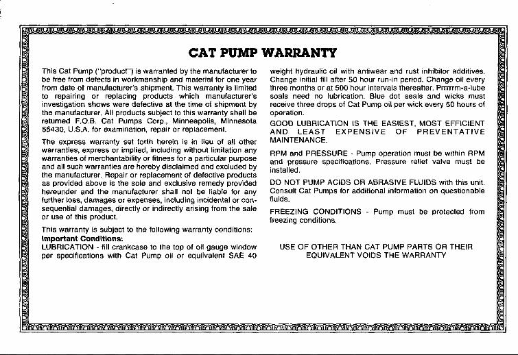
CAT PUMPThis Cat Pump (“product”) is warranted by the manufacturer tobe free from defects in workmanship and material for one yearfrom date of manufacturer’s shtpment. This warranty is limitedto repairing or replacing products which manufacturer’sinvestigation shows were defective at the time of shipment bythe manufacturer. All products subject to this warranty shall bereturned F.O.B. Cat Pumps Corp., Minneapolis, Minnesota55430, U.S.A. for examination, repair or replacement.
The express warranty set forth herein is in lieu of all otherwarranties, express or implied, including without limitation anywarranties of merchantability or fitness for a particular purposeand all such warranties are hereby disclaimed and excluded bythe manufacturer. Repair or replacement of defective productsas provided above is the sole and exclusive remedy providedhereunder and the manufacturer shall not be liable for anyfurther loss, damages or expenses, including incidental or con-sequential damages, directly or indirectly arising from the saleor use of this product.
This warranty is subject to the following warranty conditions:Important ConditionsLUBRICATION - fill crankcase to the top of oil gauge windowper specifications with Cat Pump oii or equivalent SAE 40
WARW4NTYweight hydraulic oil with antiwear and rust inhibitor additives.
Change initial fill after 50 hour run-in period. Change oil everythree months or at 500 hour intervals thereafter. Prrrrrm-a-lubeseals need no lubrication. Blue dot seals and wicks mustreceive three drops of Cat Pump oil per wick every 50 hours ofoperation.
GOOD LUBRICATION IS THE EASIEST, MOST EFFICIENTAND LEAST EXPENSIVE OF PREVENTATIVEMAINTENANCE.
RPM and PRESSURE - Pump operation must be within RPMand pressure specifications. Pressure relief valve must beinstalled.
DO NOT PUMP ACIDS OR ABRASIVE FLUIDS with this unit.Consult Cat Pumps for additional information on questionablefluids.
FREEZi NG CONDITIONS - Pump must be protected fromfreezing conditions.
USE OF OTHER THAN CAT PUMP PARTS OR THEIREQUIVALENT VOIDS THE WARRANTY

ELECTRIC
I
1
1
L.
To DashPanel
nTn GmAnnu - u.- . . . .Vacuum Tank Kill Emergency Brake
Switch Switch
~B’ack\$r..-
+b,. 1;
,;
+
Pump Clutch.Magnet
‘--iii--” ! Iii . . . .. .. I,
T’~‘i Drive Clutch,1I \ MagnetL-J
L’”Vacuum- ]Ienold
I
,--L4JL--I-M----I ----------------------- Ill I l_,-,~w
mfY* Sensor ‘4
-Master
??
To MotolBrakeCylinder
I
jk—~) f‘Ba’L Green (Gray) (T. Tach Se.sor)~
Brown (To Master Brake Cyhnder)
Fled/White (MIX Tank KIII Sw[lch)

ELECTRICAL SYSTEMThe entire electrical system operates on 12 volts DC which is pro- NOTE: When new battery is installed insure it is properly chargedvialed by your truck’s battery. Battery levels are sustained by a before installation or damage to the charging regulator may occur.alternator designed within the engine.
PROBLEM: Low Battery Voltage
Cause Solution
Defective battery. Remove and replace.
Corroded battery terminals. Clean terminals and battery posts.
Low battery fluid. Add water to appropriate level.
Loose wiring within electrical system. Examine all terminal connections and verify that they aresecure.
Electrical short in wiring system. Examine electrical systems for bare wires.
Poor ground connection. Examine terminal and remove corrosion if necessary.
PROBLEM: Inoperative Hour Meter
Cause Solution
Time is not advancing correctly. Verify 12 volts DC is available at the hour meter with theignition switch turned on. This can be accomplished witha volt meter or a test lamp.
Remove and replace hour meter if 12 volts is available.
A nylon gear within the clock may have been jammed due toa sudden jolt of the machine or truck. You may try simplytapping on the meter to try to free the nylon gear.

MAINTENANCE PROCEDURESTo avoid costly repairs and down-time, it is imperative to developand practice good maintenance procedures from the beginning.These procedures fall into daily, weekly, monthly and quarterly in-crements, and are outlined below. We have provided amaintenance log for your convenience on page 39; it is recom-mended that you affix a copy of the log on the vehicle door nearyour unit for convenience and to serve as a maintenance reminder.
Daily* Check engine oil level.
● Inspect garden hose screen - clean as needed.
* Visually inspect machine for loose wires, oil leaks, water leaks,etc.
● Inspect recovery tank s/s filter and filter bag for tears, holes, etc.- clean, repair or replace as needed.
$ Lubricate blower with LPS-1 or WD-40 through blower inlet.
Daily: Wipe machine down thoroughly with a damp cloth; flushrecovery tank out thoroughly. Empty filter bag and inspect for rips,tears, etc. - replace as needed; remove, thoroughly clean andreinstall stainless steel filter screen in recovery tank; inspect andclean vacuum slot on cleaning wand; check wand head for sharpedges that could tear carpet - file down as needed; clean wand tomaintain original appearance; wipe down vacuum and highpressure hoses as needed - visually inspect for cuts, etc.
Weekly“ Check engine air cleaner filter - clean as necessary.
● Check high pressure pump oil - add as necessary.● Check pump drive belt for wear - tighten as needed.● Check pump pulleys - tighten as needed.
● Check lines for wear/chafing.
● Check all nuts and bolts - tighten as needed.
0 Clean vacuum tank thoroughly with high pressure washer,o Flush water and chemical system with 50/50 white vinegar
solution.
o Check engine RPM’s - adjust to 2600 RPM’s at the pump.
iMPORTANT: Record date and machine hours on maintermncechart.
Monthly● Grease blower bearing fittings.
● Remove pressure bypass valve stem, grease cup and stem,reinstall.
* Check water level in battery. Clean connections as needed.
IMPORTANT: Record date and machine hours on maintenancechart.
Quarterly● Change oil in blower (see blower manual).
OVERALL CARE OF UNITMAINTAINING THE ORIGINAL APPEARANCE OF YOUR UNITIS IMPORTANT FOR TWO REASONS:
1,
2.
It represents a big dollar investment for your cleaning bustnessand its appearance should reflect that fact. A dirty machine mnot professional!
Maintenance, troubleshooting, and repair is much easier to ac-complish on a clean well maintained unit. Regular cleaning ofthe machine offers you an opportunity to visually inspect allfacets of the machine and spot potential problems before theyoccur.

.:,,”.
..w,
,,..
.:’.
,‘--
..
..
..
.,.
.,.’
‘.
JIJ
>0
>0
—
.
....
.’.
..-
..
..
.,.
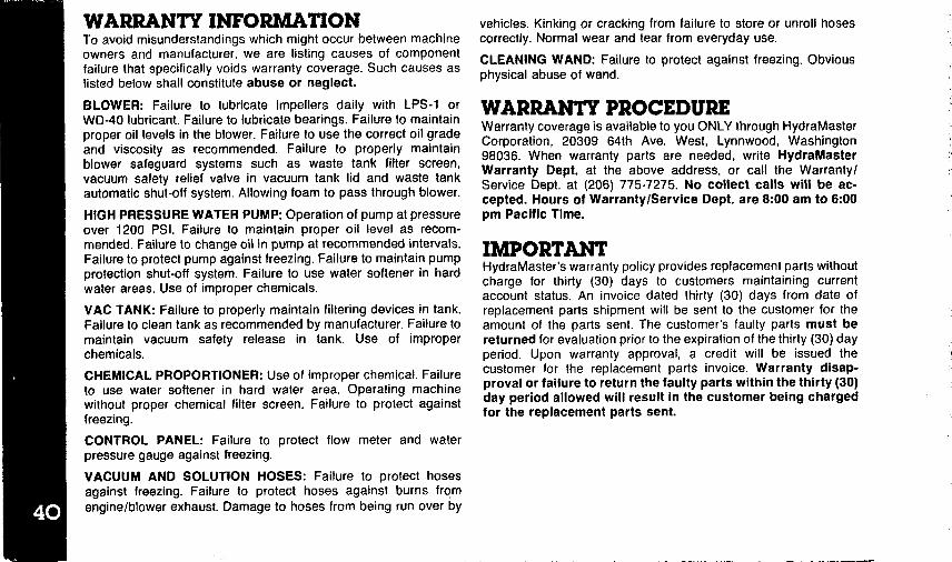
To avoid misunderstandings which might occur between machineowners and manufacturer, we are listing causes of componentfailure that specifically voids warranty coverage. Such causes aslisted below shall constitute abuse or neglect.
BLOWER: Failure to lubricate impellers daily with LPS-1 orWD-40 lubricant. Failure to lubricate bearings. Failure to maintainproper oil levels in the blower. Failure to use the correct oil gradeand viscosity as recommended. Failure to properly maintainblower safeguard systems such as waste tank filter screen,vacuum safety relief valve in vacuum tank lid and waste tankautomatic shut-off system. Allowing foam to pass through blower.
HIGH PRESSURE WATER PUMP Operation of pump at pressureover 1200 PSI. Failure to maintain proper oil level as recom-mended. Failure to change oil in pump at recommended intervals.Failure to protect pump against freezing. Failure to maintain pumpprotection shut-off system. Failure to use water softener in hardwater areas. Use of improper chemicals.
VAC TANK: Failure to properly maintain filtering devices in tank.Failure to clean tank as recommended by manufacturer. Failure tomaintain vacuum safety release in tank. Use of improperchemicals.
CHEMICAL PROPORTIONER: Use of improper chemical. Failureto use water softener in hard water area. Operating machinewithout proper chemical filter screen. Failure to protect againstfreezing.
CONTROL PANEL: Failure to protect flow meter and waterpressure gauge against freezing.
VACUUM AND SOLUTION HOSES: Failure to protect hosesagainst freezing. Failure to protect hoses against burns fromengine/blower exhaust. Damage to hoses from being run over by
..
?
vehicles. Kinking or cracking from failure to store or unroll hosescorrectly. Normal wear and tear from everyday use.
CLEANING WAND: Failure to protect against freezing. Obviousphysical abuse of wand.
Warranty coverage is available to you ONLY through HydraMasterCorporation, 20309 64th Ave. West, Lynnwood, Washington98036. When warranty parts are needed, write HydraMasterWarranty Dept. at the above address, or call the Warranty/Service Dept. at (206) 775-7275. No collect calls will be ac-cepted. Hours of Warranty/Service Dept. are 8:00 am to 6:00pm Pacific Time.
.,...
HydraMaster’s warranty policy provides replacement parts withoutcharge for thirty (30) days to customers maintaining currentaccount status. An invoice dated thirty (30) days from date ofreplacement parts shipment will be sent to the customer for theamount of the parts sent. The customer’s faulty parts must bereturned for evaluation prior to the expiration of the thirty (30) dayperiod. Upon warranty approval, a credit will be issued thecustomer for the replacement parts invoice. Warranty disap-proval or failure to return the faulty parts within the thirty (30)day period allowed will result in the customer being chargedfor the replacement parts sent.
. . .... _. ...,.,

.,:..
,....
:.::
.,,,.
.,...
,.-
...-
.
–——