ce 642 introduction - i kuweb.iku.edu.tr/~asenturk/hydraulics_files/ce 642 introduction.pdf ·...
TRANSCRIPT

1
CE 642
HYDRAULICS
Dr. Emre Can

� Tentative Course Outline
� Introduction � Pipe Flow� Open Channel Flows
� Uniform Flow� Non-Uniform Flow� Local Changes in Water Levels
� Channel Controls� Sedimentation in Open Channels and Rivers� Dimensional Analysis & Theory of Models
HYDRAULICS

EXAM SCHEDULE
� 31 March 15:00 Midterm exam 1� 12 May 15:00 Midterm exam 2� The exams will always be closed book,
(however formula sheets will be provided)
� Questions will be in English and there will be no translation of questions into Turkish,
� Answers to all the questions should be in English.
HYDRAULICS
REFERENCES:
� Chow, V.T., Open Channel Hydraulics, , Mc Graw Hill, New York, 1959.
� Henderson, F.M., Open Channel Flow, Macmillan Co, 1966.
� Vennard, J.K. & Street, R.L., Elementary Fluid Mechanics,John Wiley & Sons, 1977.
� Linsley, R.K. & Franzini, J.B., Water Resources Engineering, McGraw Hill, Newyork, 1972

HYDRAULICS
REFERENCES:
� Sümer, B.M, Ünsal, İ. & Bayazıt M. Hidrolik,Birsen yayınevi
� Yanmaz, A. Melih, Applied Water Resources Engineering, Metu Press, 3rd edition, 2006
� CE 372 Hydromechanics Lecture Notes, Middle East Technical University, Civil Engineering Department
� UTAH STATE UNIVERSITY Open Coursewarehttp://ocw.usu.edu/Civil_and_Environmental_Engineering/Fluid_Mechanics
Scope of the Course
� In many water systems, transportation of water from one location to another is the main concern.
� Two main modes of transportation are:
� Closed conduits with pressurized flow inside� Open conduits with free surface flow inside
� The main objective in this course is to study the flow in closed conduits (mainly pipes) and in open channels

Examples include:
� Water distribution networks in urban areas
� Water transmission line from Çamlıdere Dam to İvedik Water Treatment Plant
(φφφφ = 3.4 m, L = 15.5 km)
� Urfa Tunnels from Atatürk Dam to Harran Plain (φφφφ = 7.62 m, L = 2 x 26.4 km)
� Main irrigation canal in Harran Plain
� (L=118 km, Q = 80 m3/s)

The View of Atatürk Dam

GAP WATER RESOURCES ROJECTS
Total 22 dams, 19 HPP
1.7 million ha, 7485 MW, 27 billion kWh
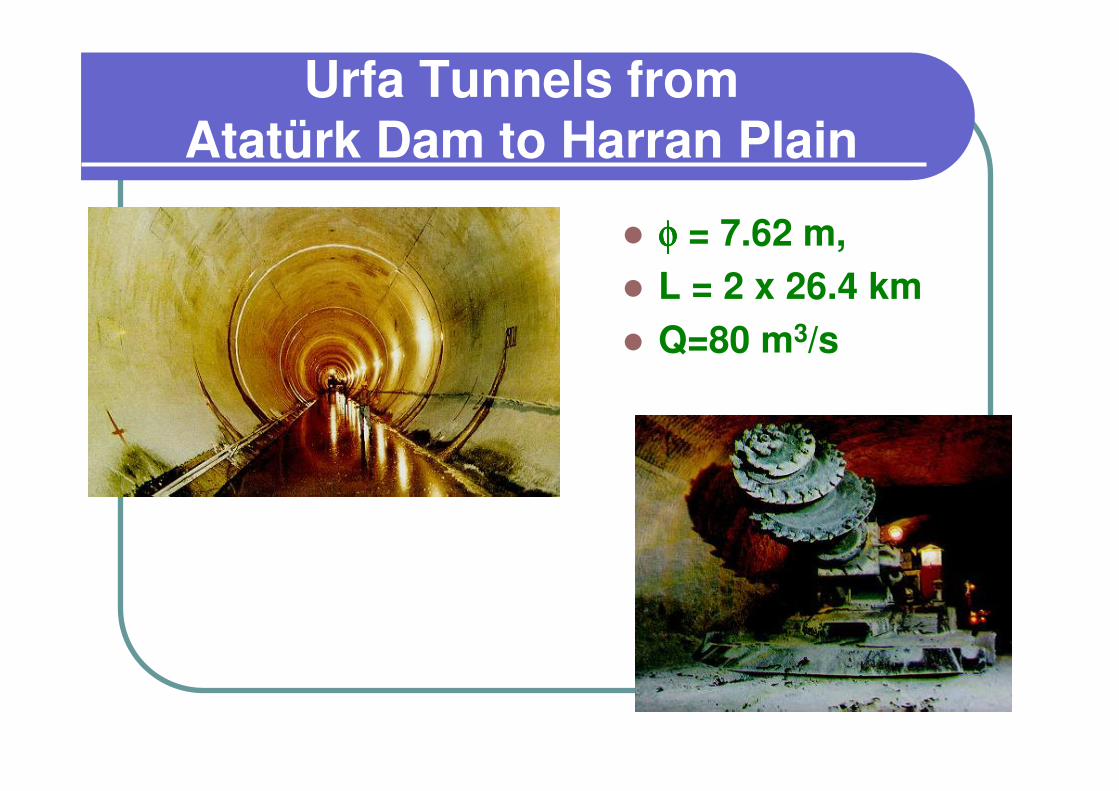
Urfa Tunnels from Atatürk Dam to Harran Plain
� φφφφ = 7.62 m,
� L = 2 x 26.4 km
� Q=80 m3/s

Main irrigation canal in Harran Plain (L=118 km, Q = 80 m3/s)

Before 1995

HARRAN PLAINHARRAN PLAIN

YEYEŞİŞİLLÇÇAY SYSTEMAY SYSTEM
BLACKSEAYEŞİLÇAY REG.
SUNGURLUDAMİSAKÖY
DAM
KABAKOZDAM
DARLIKDAM
EMİRLİ TREATMENT
ÖMERLİDAM
AĞVA
M A R M A R A SEA
STORAGE

YEŞİLÇAY SYSTEM CHARACTERISTICS
Length of transmission lines: 723 712 m
Length of water Network : 11 738 km
Volume of water reservoir : 914 000 m3
Water Supplied (2003) : 920 million m3/year
Water treatment capacity : 3.5 million m3/day

Ø3 000 mm Prestressed Concrete Cylinder Pipes

BLACKSEACumhuriyet
Pompa İstasyonu
Cumhuriyet Pompa İstasyonu
Hüseyinli Su Arıtma Tesisi
700 000 m³/gün
Hüseyinli Su Arıtma Tesisi
700 000 m³/günŞile-Alaçalı
Tünel 3.5 km
Şile-AlaçalıTünel 3.5 km
Melen Pompa İstasyonu
Melen Pompa İstasyonu
Melen Regülatörü
8.5 m3/s
Melen Regülatörü
8.5 m3/s
Melen Barajı(ileri aşama)
Melen Barajı(ileri aşama)
Melen-Alaçalıİsale Hattı
131 km
Melen-Alaçalıİsale Hattı
131 km
AlaçalıBarajı
AlaçalıBarajı
Hamidiye Tüneli 5.2
km
Hamidiye Tüneli 5.2
km
Ömerli Barajı(mevcut)
Ömerli Barajı(mevcut)
Alaçalı-Ömerli Hattı
Alaçalı-Ömerli Hattı
Bekleme Tüneli 1.3 km
Bekleme Tüneli 1.3 km
Beykoz Tüneli2.6 km
Beykoz Tüneli2.6 km
Ortaçeşme Tüneli0.8 km
Ortaçeşme Tüneli0.8 km
AyazağaTüneli2.8 km
AyazağaTüneli2.8 km
Osmankuyu Su deposu
Osmankuyu Su deposu
Boğaz Tüneli5.5 km
Boğaz Tüneli5.5 km
Boğaz Tüneli Profili
Boğaz Tüneli Profili
Boğaz TüneliBoğaz Tüneli
Boğaz Tüneli Ø=4.0-3.6 m
L=5.5 km
Boğaz Tüneli Ø=4.0-3.6 m
L=5.5 km
MARMARA SEA
GREATER MELEN PROJECT OF ISTANBUL
GREATER MELEN PROJECT OF ISTANBUL
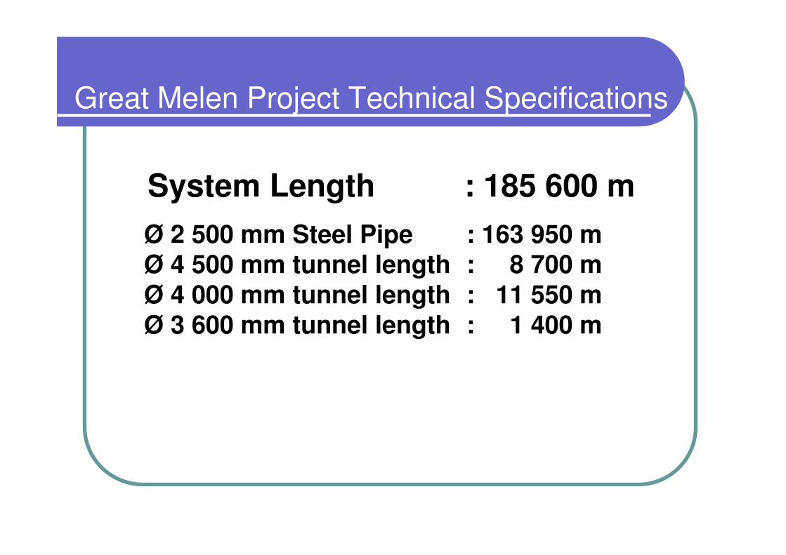
Great Melen Project Technical Specifications
System Length : 185 600 m
Ø 2 500 mm Steel Pipe : 163 950 mØ 4 500 mm tunnel length : 8 700 mØ 4 000 mm tunnel length : 11 550 mØ 3 600 mm tunnel length : 1 400 m
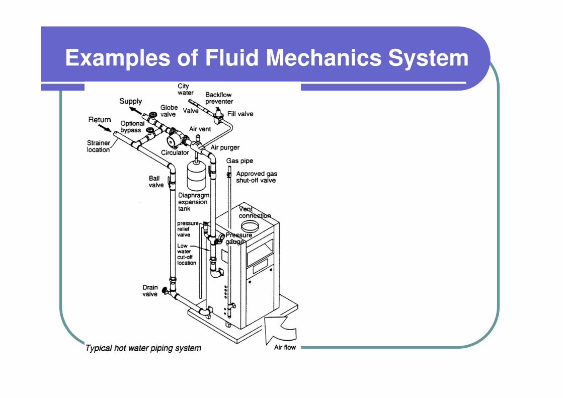
Examples of Fluid Mechanics System
Physical Properties of Fluids
� Density
� Specific weight
� Specific Gravity
� Specific Volume
� Viscosity
� Surface Tension
� Vapor Pressure
� Compressibility

Density, ρ
� Mass per unit volume
� ρ = m/∀
� [ρ]=ML-3

Specific Weight, γ:
� Weight per unit volume
� γ = W/∀
� [γ]=FL-3
γ = ρg

Specific Gravity, SG
� The ratio of the density of the fluid to the density of water (or air) at standard conditions
w
liquid)SG(ρ
ρ=
air
gas)SG(ρ
ρ=

Density and Specific Weights of some fluids (g=9.81m/s2)
Gases
Fluid Temperature°C
Densitykg/m3
Specific WeightN/m3
Water 4.0 1000. 9810.
Mercury 20.0 13600. 133416.
Gasoline 15.6 680. 6671.
Alcohol 20.0 789. 7740.
Air 15.0 1.23 12.0
Oxygen 20.0 1.33 13.0
Hydrogen 20.0 0.0838 0.822
Methane 20.0 0.667 6.54
Liq
uid
sG
ase
s

Deformation of fluid for a short time interval ∆t
τ=∝ hA
hFUp F
Up∆S
h
A
B B’
∆θy
u(y)
τ
x
h
Up∝τ
dt
dθ∝τ
Shear stress is proportional to the rate of angular deformation

Newton’s Law of Viscosity
For the linear velocity profile
y
)y(u
h
Up=
yh
U)y(u p
=
dt
d
h
U
dy
du p θ==
dy
du∝τ
Newton’sLaw of
viscositydy
duµ=τ The proportionality constant µ is known as
dynamic viscosity of the fluid.
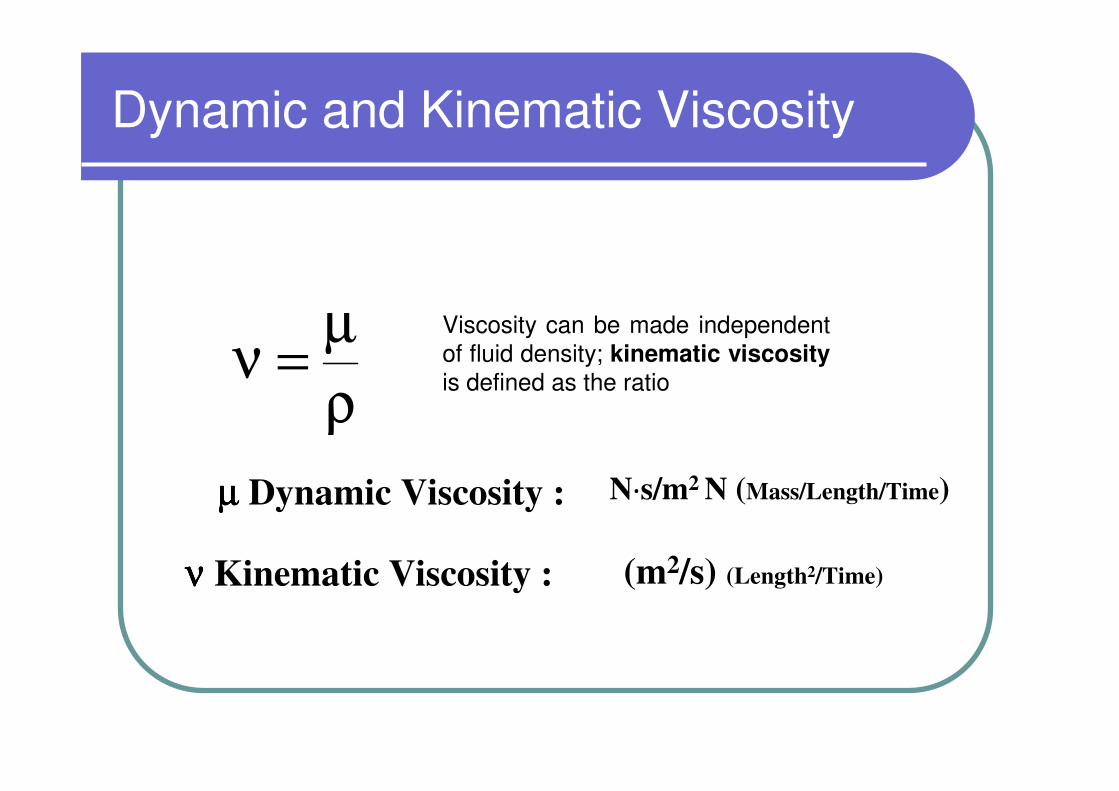
Dynamic and Kinematic Viscosity
Viscosity can be made independent of fluid density; kinematic viscosityis defined as the ratio
ρ
µ=ν
µµµµ Dynamic Viscosity : N⋅⋅⋅⋅s/m2 N (Mass/Length/Time)
νννν Kinematic Viscosity : (m2/s) (Length2/Time)

Viscosities of air and water
Fluid Temperature(°°°°C)
µµµµ
(N⋅⋅⋅⋅s/m2)νννν
(m2/s)
Water 20 1.00E-03 1.01E-06
Air 20 1.80E-05 1.51E-05

Reynolds Experiment
Q=VA Dye streak
Dye
pipe
Smooth well-rounded entrance
D


Characteristics of Turbulent Flow

Velocity components in a turbulent pipe flow: (a) x-component velocity; (b) r-component velocity; (c) θ-component velocity.

Type of Flow
� Re…Dimensionless numberf( velocity, diameter, viscosity)
� Laminar flow: Re < 2000
� Transitional flow: 2000 < Re < 4000
� Turbulent flow: Re > 4000
νπ=
ν D
Q4VD = Re