ce5000-120ap user's manual - graphtec corporation · ii safety precautions safety precautions...
TRANSCRIPT

CE5000-120AP
USER’S MANUAL�MANUAL NO.CE50AP-UM-152
CUTTING PRO
To Ensure Safe and Correct Use
i
To Ensure Safe and Correct Use
• To ensure the safe and correct use of your cutting plotter, read this manual thoroughly prior to use.
• After reading this manual, keep it in a handy location for quick reference as necessary.
• Do not allow small children to touch the cutting plotter.
• The following describes important points for safe operation. Be sure to observe them strictly.
Conventions Used in This Manual
To ensure the safe and accurate use of the cutting plotter as well as to prevent human injury and propertydamage, the safety precautions provided in this manual are ranked in the three categories described below.Be sure to gain a full understanding of the difference between each of the categories before reading theManual.
DANGERThis category provides information that, if ignored, is highly likely to cause fatal or serious injury tothe operator.
WARNINGThis category provides information that, if ignored, is likely to cause fatal or serious injury to theoperator.
CAUTIONThis category provides information that, if ignored, could cause injury to the operator or damage tothe cutting plotter.
Description of Safety Symbols
The symbol indicates information that requires careful attention (including warnings). The specificpoint requiring attention is described by an illustration or text within or next to the symbol.
The indicates an action that is prohibited. Such prohibited action is described by an illustrationor text within or next to the symbol.
The symbol indicates an action that must be performed. Such imperative action is described byan illustration or text within or next to the symbol.

ii
Safety Precautions
Safety Precautions WARNING
If the cutting plotter generates smoke, overheats, emits a strange odor, or otherwise functions abnormally,do not continue using it. Turn off the power and unplug the power cord from the electrical socket.• Use of the cutting plotter in such a condition may result in a fire hazard or
electric shock.
• After confirming that smoke is no longer being emitted, contact your salesrepresentative or nearest Graphtec vendor for repairs.
• Never attempt to perform repairs yourself. Repair work by inexperiencedpersonnel is extremely dangerous.
Do not disassemble, repair, or remodel the cutting plotter.• Such action may cause electric shock or a fire hazard due to current
leakage.
• Contact with the high-voltage parts within the cutting plotter may causeelectric shock.
• If the cutting plotter requires repairs, contact your sales representative ornearest Graphtec vendor.
Do not use the cutting plotter in a location where it will be exposed to water, rain, or snow.• Such locations may cause electric shock or a fire hazard due to current
leakage.
Be sure to ground the earth terminal.• If the cutting plotter is not grounded, the operator could suffer an electric
shock in the event of current leakage.
Do not connect the cutting plotter to a non-rated power supply.• Use of a different supply voltage may result in electric shock or a fire
hazard due to current leakage.
Prohibited
No disassembly
Avoid water
Beware ofelectric shock
Prohibited
Ground thecutting plotter
Safety Precautions
iii
Safety Precautions WARNING
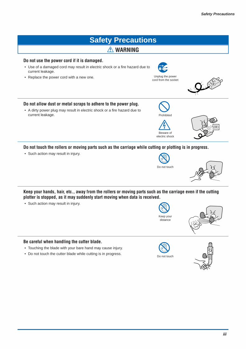
Do not use the power cord if it is damaged.• Use of a damaged cord may result in electric shock or a fire hazard due to
current leakage.
• Replace the power cord with a new one.
Do not allow dust or metal scraps to adhere to the power plug.• A dirty power plug may result in electric shock or a fire hazard due to
current leakage.
Do not touch the rollers or moving parts such as the carriage while cutting or plotting is in progress.• Such action may result in injury.
Keep your hands, hair, etc., away from the rollers or moving parts such as the carriage even if the cuttingplotter is stopped, as it may suddenly start moving when data is received.• Such action may result in injury.
Be careful when handling the cutter blade.• Touching the blade with your bare hand may cause injury.
• Do not touch the cutter blade while cutting is in progress.
Unplug the powercord from the socket
Prohibited
Beware ofelectric shock
Do not touch
Keep yourdistance
Do not touch

iv
Safety Precautions
Safety Precautions CAUTION
Do not use or store the cutting plotter in a location exposed to direct sunlight or the direct draft of an airconditioner or heater.• Such locations may impair the performance of the cutting plotter.
Do not use the cutting plotter in an excessively dusty or humid location.• Such locations may impair the performance of the cutting plotter.
Do not use the cutting plotter in a location subject to excessive mechanical vibration or electrical noise.• Use in such locations may impair the performance of the cutting plotter.
Do not place any receptacle containing water or other fluid on top of the cutting plotter.• Fluid falling inside the cutting plotter may cause electric shock or a fire
hazard due to current leakage.
If water or foreign matter enters the cutting plotter, discontinue use. Turn off the power and unplug thepower cord from the electrical socket.• Use of the cutting plotter in such a condition may result in electric shock or
a fire hazard due to current leakage.
• Contact your sales representative or nearest Graphtec vendor for repairs.
When disconnecting the power cord or interface cable, do not pull on the cord/cable.• Such action will damage the cord/cable, resulting in a fire hazard or electric
shock.
Prohibited
Unplug the powercord from the socket
Prohibited
Prohibited
Beware ofelectric shock
Avoid fluids
Beware ofelectric shock
Prohibited

Safety Precautions
v
Do not attempt to lubricate the cutting-plotter mechanisms.• Such action may cause it to break down.
Do not clean the cutting plotter using volatile solvents such as thinner or benzene.• Such action may impair its performance.
Provide sufficient space around the cutting plotter so that it does not strike any objects in its vicinity duringcutting or plotting. Such contact may cause misalignment in cutting or plotting.• Such contact may cause cutting or plotting to go out of alignment.
When using indoor lighting such as fluorescent or other electrical lamps, provide a distance of at least onemeter between the cutting plotter and the light source.• Close proximity of such a light source may cause the sensor to malfunction
and prevent proper size detection of the media.
When using the cutter, take care not to extend the blade more than necessary.• An overly extended blade will damage the cutting mat and adversely affect
the cutting quality.
Move the pen carriage slowly when moving it manually in order to load the medium or for other reasons.• Moving it quickly may damage the cutting plotter.
Safety Precautions CAUTION
Prohibited
Prohibited
Do not touch
vi
Selecting a Power Cable
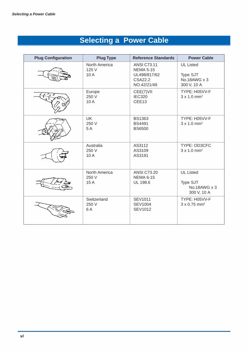
Selecting a Power Cable
Plug Configuration Plug Type Reference Standards Power Cable
North America ANSI C73.11 UL Listed125 V NEMA 5-1510 A UL498/817/62 Type SJT
CSA22.2 No.18AWG x 3NO.42/21/49 300 V, 10 A
Europe CEE(7)VII TYPE: H05VV-F250 V IEC320 3 x 1.0 mm2
10 A CEE13
UK BS1363 TYPE: H05VV-F250 V BS4491 3 x 1.0 mm2
5 A BS6500
Australia AS3112 TYPE: OD3CFC250 V AS3109 3 x 1.0 mm2
10 A AS3191
North America ANSI C73.20 UL Listed250 V NEMA 6-1515 A UL 198.6 Type SJT
No.18AWG x 3300 V, 10 A
Switzerland SEV1011 TYPE: H05VV-F250 V SEV1004 3 x 0.75 mm2
6 A SEV1012

Preface
vii
Preface
Thank you for choosing a Graphtec CE5000-120AP cutting plotter. This cutting plotter employs a digital servodrive system to achieve high-speed and high-precision cutting operations. Besides cutting apparel paper andother media, it can also be used as a pen plotter.To ensure good cutting quality and optimum productivity, be sure to read this User's Manual thoroughlybefore use.
(1) Specified rating
(2) Watch out for electrical shock
(3) Prevent dust or metallic matter from adhering to the power supply connector.
Notes on this Manual
(1) No part of this publication may be reproduced, stored in a retrieval system, or transmitted, in any form orby any means, without the prior written permission of Graphtec Corporation.
(2) The product specifications and other information in this manual are subject to change without notice.
(3) While every effort has been made to provide complete and accurate information, please contact yoursales representative or nearest Graphtec vendor if you find any unclear or erroneous information or wishto make other comments or suggestions.
(4) Notwithstanding the stipulations in the preceding paragraph, Graphtec Corporation assumes no liabilityfor damages resulting from either the use of the information contained herein or the use of the product.
Registered Trademarks
All names of companies, brands, logotypes, and products appearing in this manual are the trademarks orregistered trademarks of their respective companies.
Copyright
This User's Manual is copyrighted by Graphtec Corporation.
Precautions regarding paper
Paper is easily affected by temperature and humidity, and starts to expand and contract immediately after ithas been pulled out from the roll. If cutting or plotting is started immediately after the paper has been pulledout from the roll, expansion or contraction of the paper during the cutting/plotting operation may causemisaligned cutting/plotting.On this cutting plotter, the default settings for the two functions provided to prevent misaligned cutting/plottingare "UNTIL: 180 seconds" and "PAPER LOAD: 2". To change these settings, see "4.34 Setting the PAPERREADY TIME" and "4.35 Setting the PAPER LOAD Function".

viii
Contents
Contents
To Ensure Safe and Correct UseConventions Used in This Manual ........................................................................................................ iDescription of Safety Symbols ............................................................................................................. i
Safety Precautions .......................................................................................................................................... iiSelecting a Power Cable ............................................................................................................................... viPreface ...........................................................................................................................................................vii
1 Introduction1.1 Checking the Accessories ........................................................................................................ 1-21.2 Parts Names and Functions ..................................................................................................... 1-3
Front View.............................................................................................................................. 1-3Rear View ............................................................................................................................... 1-4Control Panel ........................................................................................................................ 1-5
1.3 Assembling the Stand ............................................................................................................... 1-6Stand Construction .............................................................................................................. 1-6Basket Construction ............................................................................................................ 1-6Assembling the Stand .......................................................................................................... 1-7
2 Setting up The Cutter Plotter2.1 Connecting to Your Computer .................................................................................................. 2-22.2 Turning on the Power ................................................................................................................ 2-32.3 Loading the Medium .................................................................................................................. 2-4
Loading a Roll Medium ........................................................................................................ 2-4Loading a Sheet Media ......................................................................................................... 2-9Aligning the Push Rollers .................................................................................................. 2-10
2.4 If the sensor detects that there is no paper left while roll paper is being cut ................... 2-122.5 Adjusting and Mounting the Cutter Pen ................................................................................ 2-13
Types and Features of Cutter Blades ............................................................................... 2-13Cutter Pen Construction .................................................................................................... 2-13Replacing the Cutter Blade................................................................................................ 2-14Adjusting the Blade Length ............................................................................................... 2-14Mounting the Cutter Pen .................................................................................................... 2-15
2.6 Mounting the Pen ..................................................................................................................... 2-16
3 Basic Settings and Operations3.1 Setting the Cutter-Pen Conditions ........................................................................................... 3-2
Storing and Selecting Cutter Pen Condition Setting Areas.............................................. 3-3Setting TOOL (cutter blade or pen) ..................................................................................... 3-3Setting OFFSET .................................................................................................................... 3-4Setting FORCE ...................................................................................................................... 3-4Setting SPEED ...................................................................................................................... 3-4Setting QUALITY ................................................................................................................... 3-5
3.2 Displaying the Effective Cutting Area ...................................................................................... 3-63.3 Moving the Pen .......................................................................................................................... 3-63.4 Setting the Initial Cutting Position (Origin Point) ................................................................... 3-73.5 Stop Function............................................................................................................................. 3-8
Contents
ix
3.6 Moving the Pen Carriage in +100 mm Steps ........................................................................... 3-93.7 Test Cutting .............................................................................................................................. 3-10
4 Function Settings and Operations4.1 PAUSE Menu List ....................................................................................................................... 4-24.2 Clearing the Buffer Memory...................................................................................................... 4-34.3 Setting the FEED & CUT function ............................................................................................ 4-44.4 Blade Wear Detection (When Blade Wear Setup is On) .......................................................... 4-5
Checking the Wear Rate ....................................................................................................... 4-5Setting Wear-Rate Groups ................................................................................................... 4-6Setting Wear-Rate Factors ................................................................................................... 4-6Clearing the Total Distance (Wear Rate) ............................................................................. 4-7
4.5 Raising and Lowering the Pen ................................................................................................. 4-84.6 Selecting the Type of Perforated Line ...................................................................................... 4-94.7 Setting TANGENTIAL Mode..................................................................................................... 4-104.8 Selecting the Blade Tip's Initial Position ............................................................................... 4-114.9 Setting the PEN UP SPEED..................................................................................................... 4-124.10 Specifying the INITIAL FEED Length ..................................................................................... 4-134.11 Setting AUTO PRE-FEED ........................................................................................................ 4-144.12 Distance Adjustment ............................................................................................................... 4-154.13 Aligning the Coordinate Axes ................................................................................................ 4-164.14 Setting the Cutting/Plotting Area ........................................................................................... 4-184.15 Expanding the Cutting/Plotting Area ..................................................................................... 4-194.16 Rotating the Coordinate Axes ................................................................................................ 4-204.17 Sorting Settings ....................................................................................................................... 4-214.18 Specifying the SPACE REAR Distance .................................................................................. 4-224.19 Setting the OFFSET FORCE (Initial Cutting Force) .............................................................. 4-234.20 Setting the Initial Down Force ................................................................................................ 4-244.21 Setting the STEP PASS ........................................................................................................... 4-254.22 Setting the OFFSET ANGLE ................................................................................................... 4-264.23 Setting the F_CUT Function ................................................................................................... 4-274.24 Setting the LENGTH UNIT ....................................................................................................... 4-284.25 Adjusting the Distance Between the Pens ............................................................................ 4-294.26 Cutting/Plotting Using the Buffer Memory (COPY Function) .............................................. 4-304.27 User-specified Settings ........................................................................................................... 4-314.28 Setting the Format of Data to be Received ........................................................................... 4-32
Setting the Command Mode .............................................................................................. 4-32Setting the STEP SIZE........................................................................................................ 4-32Setting the ORIGIN POINT ................................................................................................. 4-33
4.29 Interface Settings..................................................................................................................... 4-344.30 Setting the PAGE LENGTH ...................................................................................................... 4-354.31 Setting the SEPARATOR Function ......................................................................................... 4-364.32 Setting the TIMEOUT Function ............................................................................................... 4-374.33 Setting the PAPER READY TIME ............................................................................................ 4-384.34 Setting the PAPER LOAD Function ........................................................................................ 4-394.35 TEST Mode ............................................................................................................................... 4-40
Condition-List Printing....................................................................................................... 4-40Self-Test-Pattern Printing................................................................................................... 4-40Dump Mode ......................................................................................................................... 4-41Cutting Demo ...................................................................................................................... 4-41

x
Contents
5 Setting and Using the Special Functions5.1 Description of Special Functions A ......................................................................................... 5-25.2 Setting Special Functions A ..................................................................................................... 5-45.3 Description of Special Functions B ......................................................................................... 5-5
Display Language Setting (MENU LANGUAGE SELECTION) ........................................... 5-55.4 Setting Special Functions B ..................................................................................................... 5-5
6 Troubleshooting6.1 The Cutting Plotter Does Not Operate When Turned On ........................................................ 6-26.2 The Cutting Plotter Does Not Operate Correctly .................................................................... 6-26.3 The Cutting Results Are Unsatisfactory .................................................................................. 6-36.4 An Error Message Was Displayed ............................................................................................ 6-4
AppendixAppendix A Main Specifications ....................................................................................................... A-2Appendix B Options and Supplies .................................................................................................... A-3Appendix C External Dimensions ..................................................................................................... A-4Appendix D Menu Tree ........................................................................................................................ A-5
Index .......................................................................................................................................................... I-1
CHAPTER 1Introduction
1.1 Checking the Accessories1.2 Parts Names and Functions1.3 Assembling the Stand
1-2
Introduction
1.1 Checking the Accessories
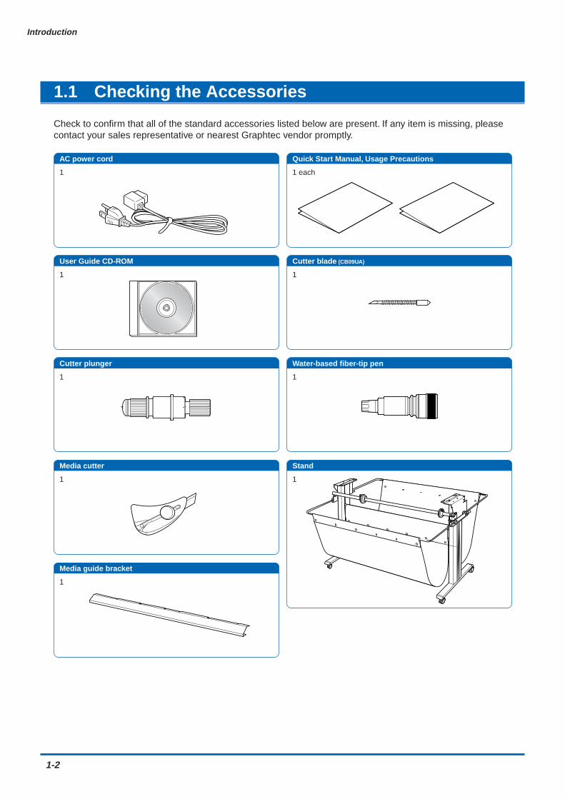
Check to confirm that all of the standard accessories listed below are present. If any item is missing, pleasecontact your sales representative or nearest Graphtec vendor promptly.
AC power cord Quick Start Manual, Usage Precautions
User Guide CD-ROM
Stand
Cutter blade (CB09UA)
Water-based fiber-tip pen
1 1 each
1
1
1
1
Cutter plunger
1
Media cutter
1
Media guide bracket
1
AC power cord Quick Start Manual Usage Precautions User Guide CD-ROMCutter blade CB09UA Cutter plunger Water-based fiber-tip penMedia cutter Stand Media guide bracket
Introduction
1-3
1.2 Parts Names and Functions
Front View
Media set lever
Control panelGrit roller
Cutting mat
Push rollersStock shaft
Stopper
Pen station
Pen carriage
Pen holderCutter pen holder
USB interface connector
Serial (RS-232C) interface connector
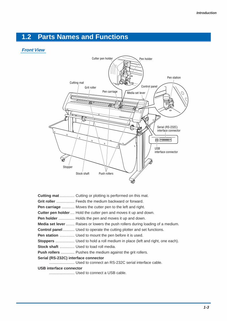
Cutting mat .............. Cutting or plotting is performed on this mat.
Grit roller ................. Feeds the medium backward or forward.
Pen carriage ............ Moves the cutter pen to the left and right.
Cutter pen holder .... Hold the cutter pen and moves it up and down.
Pen holder ............... Holds the pen and moves it up and down.
Media set lever ........ Raises or lowers the push rollers during loading of a medium.
Control panel ........... Used to operate the cutting plotter and set functions.
Pen station .............. Used to mount the pen before it is used.
Stoppers .................. Used to hold a roll medium in place (left and right, one each).
Stock shaft .............. Used to load roll media.
Push rollers ............. Pushes the medium against the grit rollers.
Serial (RS-232C) interface connector........................ Used to connect an RS-232C serial interface cable.
USB interface connector........................ Used to connect a USB cable.
1-4
Introduction
Rear View
Power switch
AC power inlet
Alignment shaft
Basket
Stand
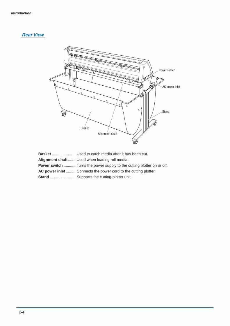
Basket ...................... Used to catch media after it has been cut.
Alignment shaft ....... Used when loading roll media.
Power switch ........... Turns the power supply to the cutting plotter on or off.
AC power inlet ......... Connects the power cord to the cutting plotter.
Stand ........................ Supports the cutting-plotter unit.

Introduction
1-5
Control Panel
Indicator Lamp
STATUS .......... Illuminates while the power to the cutting plotter isturned on, and goes out when the cutting plotter is inPAUSE status. This lamp flashes when data is beingreceived from an interface, regardless of whether ornot the cutting plotter is in PAUSE status.
Panel Keys
TEST ......... Press this function key to conduct a cutting test andcheck the cutting conditions.
PREV. ....... Press this function key to view the previous display onthe LCD when in PAUSE status.
NEXT ........ Press this function key to view the next display on theLCD when in PAUSE status.
COND. ...... Press this function key to view the cutter-pencondition settings.
PAUSE ...... Press this function key once in READY status toswitch to PAUSE status in order to change the varioussettings. Press it again to cancel the PAUSE status.Pressing this key while cutting or plotting is inprogress stops the cutting or plotting.
ENTER ...... Pressing this function key registers the cutting orplotting conditions set.
POSITION.............. These keys are used to move the cursor or change
the settings on the LCD display on the function settingscreens. Press these keys when in PAUSE status tomove the pen carriage or the medium.
ORIGIN ..... Press this function key to set the origin point. The penposition is set as the origin point when this key ispressed.
1-6
Introduction
1.3 Assembling the Stand
Stand Construction
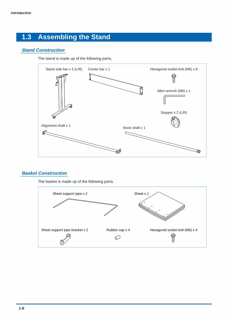
The stand is made up of the following parts.
Stand side bar x 2 (L/R) Center bar x 1
Alignment shaft x 1
Stopper x 2 (L/R)
Hexagonal socket bolt (M6) x 8
Allen wrench (M6) x 1
Stock shaft x 1
Basket Construction
The basket is made up of the following parts.
Sheet support pipe x 2
Sheet support pipe bracket x 2 Rubber cap x 4 Hexagonal socket bolt (M6) x 4
Sheet x 1
Introduction
1-7
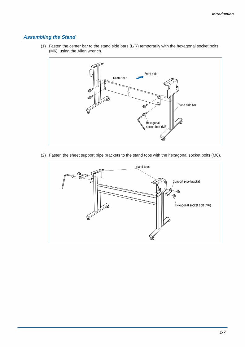
Assembling the Stand
(1) Fasten the center bar to the stand side bars (L/R) temporarily with the hexagonal socket bolts(M6), using the Allen wrench.
Front side
Stand side bar
Center bar
Hexagonal socket bolt (M6)
(2) Fasten the sheet support pipe brackets to the stand tops with the hexagonal socket bolts (M6).
Hexagonal socket bolt (M6)
Support pipe bracket
stand tops
1-8
Introduction
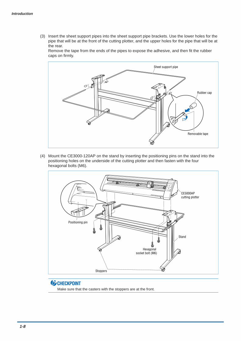
(3) Insert the sheet support pipes into the sheet support pipe brackets. Use the lower holes for thepipe that will be at the front of the cutting plotter, and the upper holes for the pipe that will be atthe rear.Remove the tape from the ends of the pipes to expose the adhesive, and then fit the rubbercaps on firmly.
Sheet support pipe
Rubber cap
Removable tape
(4) Mount the CE3000-120AP on the stand by inserting the positioning pins on the stand into thepositioning holes on the underside of the cutting plotter and then fasten with the fourhexagonal bolts (M6).
Positioning pin
Hexagonal socket bolt (M6)
Stand
CE5000AP cutting plotter
Stoppers
CHECKPOINTMake sure that the casters with the stoppers are at the front.

Introduction
1-9
(5) Attach the media guide bracket to the underside of the front panel. Loosen the two decorativescrews that are attached to the underside of the front panel (one on each side) by two or threeturns, slot the bracket in, and then tighten the screws.
Media guide bracket
Decorative screw
Pin
CAUTION• When attaching the media guide bracket, take care not to drop it on your feet or on any other
parts of your body. Make sure that the decorative screws and pins are fitted into the U-shapedcutouts on the media guide bracket.
• When loosening or tightening the decorative screws, take care not to injure yourself on any partsin their vicinity.
(6) Attach the alignment shaft to the stand tops. Loosen the attached bindhead screws A (M4) twoor three turns, and then insert the brackets on the end of the shaft using the elongated screwholes. Remove the fixing tape from the alignment shaft and then push the shaft in until itcontacts the curved area indicated by "a" in the figure below. Tighten the A (M4) bindheadscrews. When the shaft has been attached, tighten the bindhead screws B (M4), and checkthat the shaft does not rotate. The bindhead screws B are screws to prevent the shaft fromrotating. Tighten the screws so that the holes in the shaft are positioned approximately in thecenter in the horizontal direction and at the top and bottom in the rotation direction.
Bindhead screws A (M4)Bindhead screws B (M4)Fixing tape
Bracket
Alignment shaft
a
a
a
stand top
stand top
1-10
Introduction
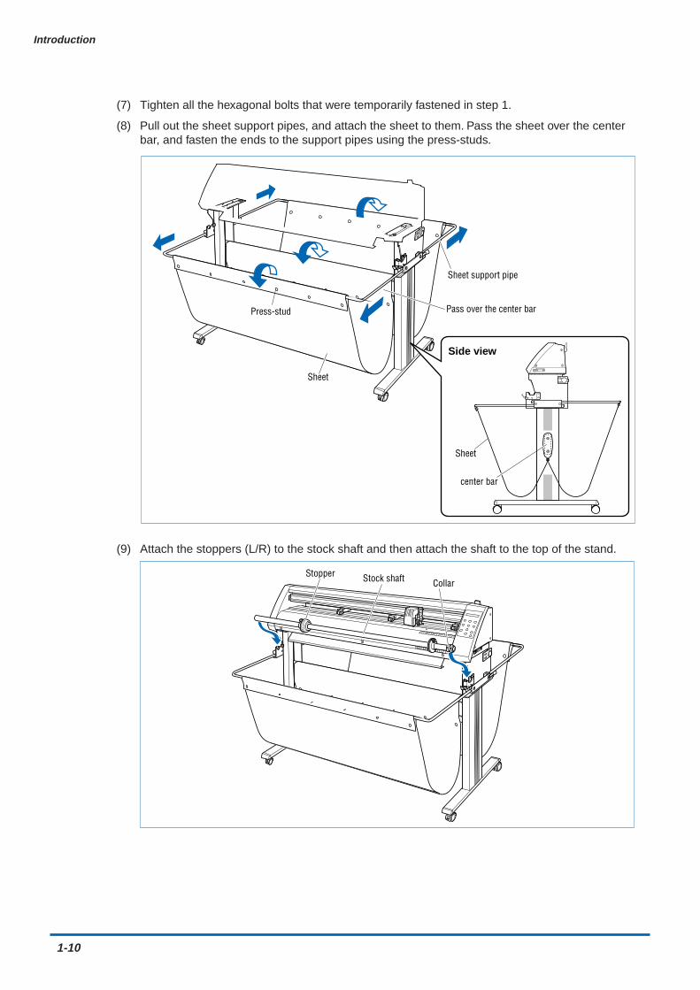
(7) Tighten all the hexagonal bolts that were temporarily fastened in step 1.
(8) Pull out the sheet support pipes, and attach the sheet to them. Pass the sheet over the centerbar, and fasten the ends to the support pipes using the press-studs.
Sheet
Pass over the center bar
Sheet support pipe
Press-stud
Side view
Sheet
center bar
(9) Attach the stoppers (L/R) to the stock shaft and then attach the shaft to the top of the stand.
Stock shaftStopperCollar
CHAPTER 2Setting up The Cutter Plotter
2.1 Connecting to Your Computer2.2 Turning on the Power2.3 Loading the Medium2.4 If the sensor detects that there is no paper
left while roll paper is being cut2.5 Adjusting and Mounting the Cutter Pen2.6 Mounting the Pen
2-2
Setting up The Cutter Plotter
2.1 Connecting to Your Computer
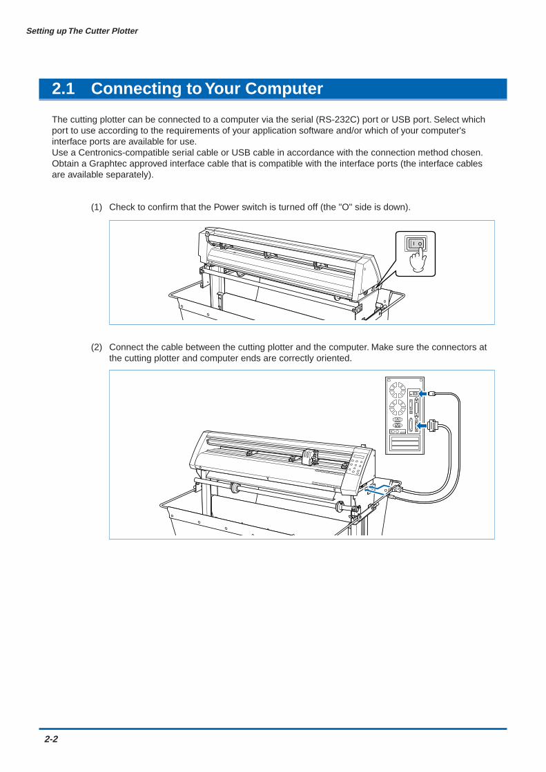
The cutting plotter can be connected to a computer via the serial (RS-232C) port or USB port. Select whichport to use according to the requirements of your application software and/or which of your computer'sinterface ports are available for use.Use a Centronics-compatible serial cable or USB cable in accordance with the connection method chosen.Obtain a Graphtec approved interface cable that is compatible with the interface ports (the interface cablesare available separately).
(1) Check to confirm that the Power switch is turned off (the "O" side is down).
(2) Connect the cable between the cutting plotter and the computer. Make sure the connectors atthe cutting plotter and computer ends are correctly oriented.

Setting up The Cutter Plotter
2-3
2.2 Turning on the Power
Connect the cutting plotter to the AC electrical socket using the power cord provided, and turn on the power.
(1) Check to confirm that the Power switch is turned off (the "O" side is down).
(2) Connect the cutting-plotter AC power inlet to a correctly rated electrical socket using the powercord provided.
(3) Turn on the cutting plotter by pressing the "|" side of the Power switch. The STATUS lamp onthe control panel will light up.
(4) If no medium has been loaded, the message below appears on the display, prompting theloading of a medium.
L O A D M E D I A ! !
If a medium has already been loaded, the current media setting is displayed as shown below.
R O L L 1 P R E S S E N T R
Select the media mode to suit the medium used. For instructions on loading media andselecting the media mode, see "2.3 Loading the Medium."

2-4
Setting up The Cutter Plotter
2.3 Loading the Medium
Load the medium, aligning it with the right-hand grit roller when viewed from the front so that it registers withthe media sensor. Then, adjust the push-roller position to match the width of the medium. The cutting plottercan use media in roll or sheet form. Load the desired medium type by following the appropriate instructions.
Loading a Roll Medium
Load the roll medium onto the stock shaft on the stand.
(1) Confirm that the roll is correctly oriented, and then slide the stoppers onto the shaft.
Stock shaft
Stopper
Stopper screw
Stopper
Position the stoppers at the appropriate locations and then tighten the screws. At this time, if
you have loaded a 950-mm media roll, fix the stoppers at the positions shown in the following
diagrams. If the media roll is of a different width, loosen the stopper screws, align the roll with
the plotter’s grit roller positions, and then tighten the stopper screws.
Approx. 20 mmMount the collar so that its side with the smaller diameter contacts the white plastic part of the shaft holder.
For 2-inch diameter cores
Collar Stopper screwStock shaftStopper
Medium
Approx. 32 mmMount the collar so that its side with the smaller diameter contacts the white plastic part of the shaft holder.
For 3-inch diameter cores
Collar Stopper screwStock shaftStopper
Medium
(2) Mount the stock shaft at the front of the cutting plotter.
Setting up The Cutter Plotter
2-5
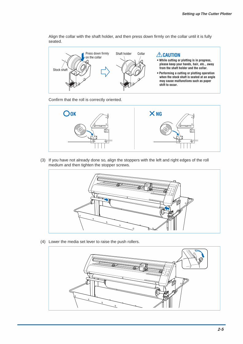
Align the collar with the shaft holder, and then press down firmly on the collar until it is fullyseated.
CAUTION• While cutting or plotting is in progress,
please keep your hands, hair, etc., away from the shaft holder and the collar.
• Performing a cutting or plotting operation when the stock shaft is seated at an angle may cause malfunctions such as paper shift to occur.
CollarShaft holderPress down firmly on the collar
Stock shaft
Confirm that the roll is correctly oriented.
NGOK
(3) If you have not already done so, align the stoppers with the left and right edges of the rollmedium and then tighten the stopper screws.
(4) Lower the media set lever to raise the push rollers.
2-6
Setting up The Cutter Plotter
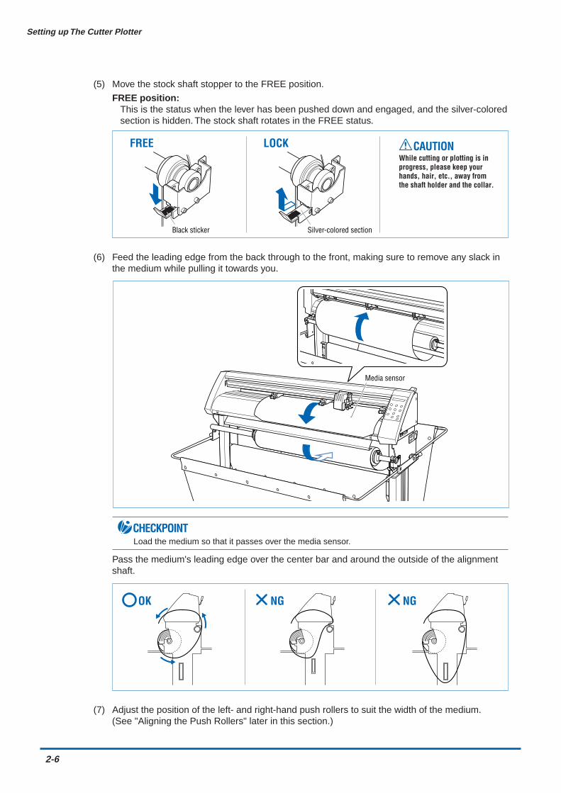
(5) Move the stock shaft stopper to the FREE position.
FREE position:This is the status when the lever has been pushed down and engaged, and the silver-coloredsection is hidden. The stock shaft rotates in the FREE status.
LOCKFREE CAUTIONWhile cutting or plotting is in progress, please keep your hands, hair, etc., away from the shaft holder and the collar.
Black sticker Silver-colored section
(6) Feed the leading edge from the back through to the front, making sure to remove any slack inthe medium while pulling it towards you.
Media sensor
CHECKPOINTLoad the medium so that it passes over the media sensor.
Pass the medium's leading edge over the center bar and around the outside of the alignmentshaft.
NG NGOK
(7) Adjust the position of the left- and right-hand push rollers to suit the width of the medium.(See "Aligning the Push Rollers" later in this section.)
Setting up The Cutter Plotter
2-7
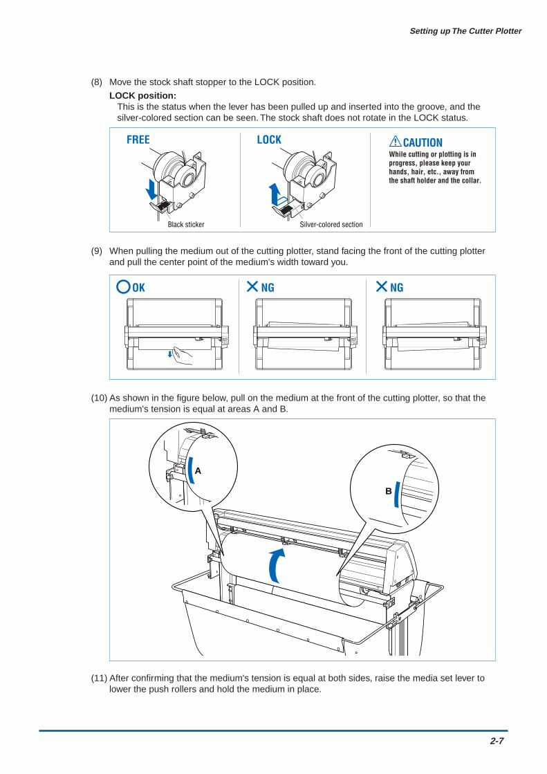
(8) Move the stock shaft stopper to the LOCK position.
LOCK position:This is the status when the lever has been pulled up and inserted into the groove, and thesilver-colored section can be seen. The stock shaft does not rotate in the LOCK status.
LOCKFREE CAUTIONWhile cutting or plotting is in progress, please keep your hands, hair, etc., away from the shaft holder and the collar.
Black sticker Silver-colored section
(9) When pulling the medium out of the cutting plotter, stand facing the front of the cutting plotterand pull the center point of the medium's width toward you.
NG NGOK
(10) As shown in the figure below, pull on the medium at the front of the cutting plotter, so that themedium's tension is equal at areas A and B.
A
B
(11) After confirming that the medium's tension is equal at both sides, raise the media set lever tolower the push rollers and hold the medium in place.
2-8
Setting up The Cutter Plotter
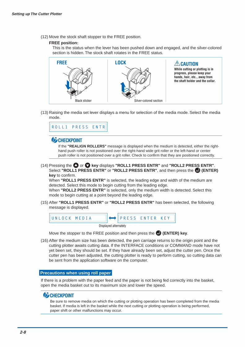
(12) Move the stock shaft stopper to the FREE position.
FREE position:This is the status when the lever has been pushed down and engaged, and the silver-coloredsection is hidden. The stock shaft rotates in the FREE status.
LOCKFREE CAUTIONWhile cutting or plotting is in progress, please keep your hands, hair, etc., away from the shaft holder and the collar.
Black sticker Silver-colored section
(13) Raising the media set lever displays a menu for selection of the media mode. Select the mediamode.
R O L L 1 P R E S S E N T R
CHECKPOINTIf the "REALIGN ROLLERS" message is displayed when the medium is detected, either the right-hand push roller is not positioned over the right-hand wide grit roller or the left-hand or centerpush roller is not positioned over a grit roller. Check to confirm that they are positioned correctly.
(14) Pressing the or key displays "ROLL1 PRESS ENTR" and "ROLL2 PRESS ENTR".Select "ROLL1 PRESS ENTR" or "ROLL2 PRESS ENTR", and then press the (ENTER)key to confirm.When "ROLL1 PRESS ENTR" is selected, the leading edge and width of the medium aredetected. Select this mode to begin cutting from the leading edge.When "ROLL2 PRESS ENTR" is selected, only the medium width is detected. Select thismode to begin cutting at a point beyond the leading edge.
(15) After "ROLL1 PRESS ENTR" or "ROLL2 PRESS ENTR" has been selected, the followingmessage is displayed.
U N L O C K M E D I A P R E S S E N T E R K E Y
Displayed alternately
Move the stopper to the FREE position and then press the (ENTER) key.
(16) After the medium size has been detected, the pen carriage returns to the origin point and thecutting plotter awaits cutting data. If the INTERFACE conditions or COMMAND mode have notyet been set, they should be set. If they have already been set, adjust the cutter pen. Once thecutter pen has been adjusted, the cutting plotter is ready to perform cutting, so cutting data canbe sent from the application software on the computer.
Precautions when using roll paper
If there is a problem with the paper feed and the paper is not being fed correctly into the basket,open the media basket out to its maximum size and lower the speed.
CHECKPOINTBe sure to remove media on which the cutting or plotting operation has been completed from the mediabasket. If media is left in the basket while the next cutting or plotting operation is being performed,paper shift or other malfunctions may occur.

Setting up The Cutter Plotter
2-9
Loading a Sheet Media
(1) Lower the media set lever to raise the push rollers.
(2) Load the medium, aligning the edges with the upper and lower scales on the front guide.
Media sensor
Align with scale
CHECKPOINTLoad the medium so that it passes over the media sensor.
(3) Adjust the position of the left- and right-hand push rollers to suit the medium width.
(4) Raising the media set lever displays a menu for selecting the media mode. Select the mediamode.
S H E E T P R E S S E N T R
CHECKPOINTIf the "REALIGN ROLLERS" message is displayed when the medium is detected, either the right-hand push roller is not positioned over the right-hand wide grit roller or the left-hand or centerpush roller is not positioned over a grit roller. Check to confirm that they are positioned correctly.
(5) Pressing the or key displays "ROLL1 PRESS ENTR", "ROLL2 PRESS ENTR", and"SHEET PRESS ENTR". Select "SHEET PRESS ENTR" and then press the (ENTER) keyto confirm the selection. When "SHEET PRESS ENTR" is selected, the front and rear edgesare detected.
(6) After the medium size has been detected, the pen carriage returns to the origin point and thecutting plotter awaits cutting data. If the INTERFACE conditions or COMMAND mode have notyet been set, they should be set. If they have already been set, adjust the cutter pen. Once thecutter pen has been adjusted, the cutting plotter is ready to perform cutting, so cutting data canbe sent from the application software on the computer.
2-10
Setting up The Cutter Plotter
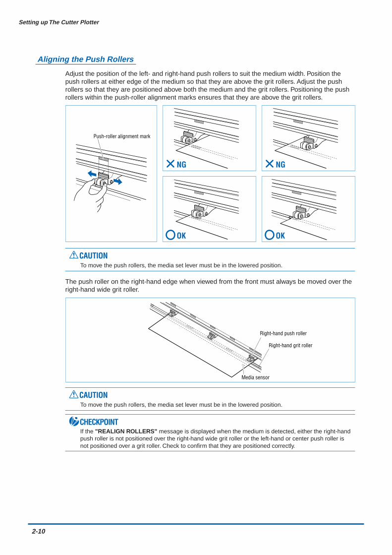
Aligning the Push Rollers
Adjust the position of the left- and right-hand push rollers to suit the medium width. Position thepush rollers at either edge of the medium so that they are above the grit rollers. Adjust the pushrollers so that they are positioned above both the medium and the grit rollers. Positioning the pushrollers within the push-roller alignment marks ensures that they are above the grit rollers.
Push-roller alignment mark
NG
OK
NG
OK
CAUTIONTo move the push rollers, the media set lever must be in the lowered position.
The push roller on the right-hand edge when viewed from the front must always be moved over theright-hand wide grit roller.
Right-hand push roller
Right-hand grit roller
Media sensor
CAUTIONTo move the push rollers, the media set lever must be in the lowered position.
CHECKPOINTIf the "REALIGN ROLLERS" message is displayed when the medium is detected, either the right-handpush roller is not positioned over the right-hand wide grit roller or the left-hand or center push roller isnot positioned over a grit roller. Check to confirm that they are positioned correctly.
Setting up The Cutter Plotter
2-11
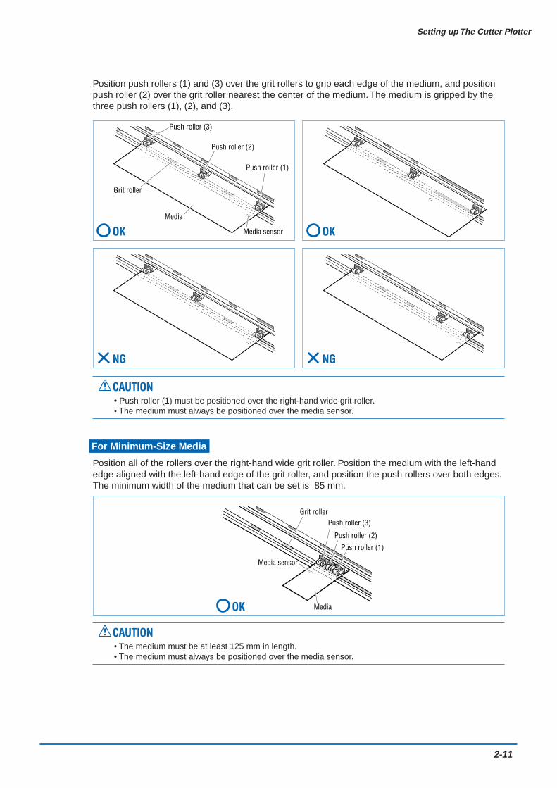
Position push rollers (1) and (3) over the grit rollers to grip each edge of the medium, and positionpush roller (2) over the grit roller nearest the center of the medium. The medium is gripped by thethree push rollers (1), (2), and (3).
Push roller (1)
Push roller (2)
Push roller (3)
Grit roller
Media sensor
Media
NG
OK
NG
OK
CAUTION• Push roller (1) must be positioned over the right-hand wide grit roller.• The medium must always be positioned over the media sensor.
For Minimum-Size Media
Position all of the rollers over the right-hand wide grit roller. Position the medium with the left-handedge aligned with the left-hand edge of the grit roller, and position the push rollers over both edges.The minimum width of the medium that can be set is 85 mm.
Media
Push roller (1)
Push roller (3)Grit roller
Media sensor
Push roller (2)
OK
CAUTION• The medium must be at least 125 mm in length.• The medium must always be positioned over the media sensor.

2-12
Setting up The Cutter Plotter
2.4 If the sensor detects that there is no paper left while roll paper is being cut
If the media sensor detects that there is no paper left during a roll paper cutting operation, cutting is stoppedautomatically. Check the length of paper remaining, and select whether to continue or abort the cuttingoperation.
(1) If the media sensor detects that there is no paper left during a roll paper cutting operation,cutting is stopped automatically and the following message is displayed.
N o M e d i a
(2) If the (ENTER) key is pressed, plotting/cutting is continued and subsequent paper enddetection is not performed. Moreover, if the media set lever is lowered and a media feedoperation performed, paper end detection will be performed once again.

Setting up The Cutter Plotter
2-13
2.5 Adjusting and Mounting the Cutter Pen
Individual cutter blades have a variety of features. Select the optimal cutter blade to suit the medium to becut.
CAUTIONTo avoid cutting your fingers, always handle the cutter blade with caution.
Types and Features of Cutter Blades
Cutter Pen Construction
The cutting plotter cuts using a cutter blade mounted in a cutter-pen plunger. There are twodifferent cutter-pen plungers to suit the diameter of the cutter blade to be mounted (the 0.9-mmcutter-pen plunger is provided as standard equipment). Be sure to mount the cutter blade in thecorresponding cutter-pen plunger.
Cutter blade
Plunger cap
Plunger
Blade-length adjustment knob(Blue: For 0.9-mm-diameter blades)(Red: For 1.5-mm-diameter blades)
Part No. andprofile
CB 09UA
CB 15U
CB 15UB
Blade diameterand offset
ø0.9 mm0.45
ø1.5 mmø0.75
ø1.5 mm0.15
Use and features
The standard blade for cutting coloradhesive-backed media. Suitable forcutting media up to 0.25 mm in thickness.Max. cutting distance: Approx. 4,000 mCapable of cutting thicker media thanpossible with the CB09UA blade. Suitablefor cutting media 0.25 mm to 0.5 mm inthickness.Suitable for detailed cutting (e.g., lettersless than 10 mm in size) of media up to0.25 mm in thickness.
Compatibleplunger
PHP32-CB09N
PHP32-CB15N
PHP32-CB15N

2-14
Setting up The Cutter Plotter
Replacing the Cutter Blade
CAUTIONTo prevent cutting your fingers, always handle the cutter blade with caution.
1.5-mm-diameter cutter pen
Plunger-capcross-section
Plunger cap
1.5-mm-dia. blades
adjustment knob (red)
Plunger
Spring
Plunger cap
Plunger-capcross-section
0.9-mm-dia. blades
0.9-mm-diameter cutter pen
adjustment knob (blue)
Plunger
(1) Turn the blade-length adjustment knob to retract the blade into the plunger.
(2) Turn the plunger cap in the counter-clockwise direction to remove it from the plunger.
(3) Remove the blade from inside the plunger cap.
(4) Insert the new blade into the hole provided in the plunger cap.
(5) With the blade inserted into the plunger cap, screw on the plunger from above.
Adjusting the Blade Length
If the blade is extended too far in relation to the thickness of the medium being cut, it will damagethe cutting mat. Be sure to adjust the blade length correctly.
CAUTIONTo prevent cutting your fingers, always handle the cutter blade with caution.
(1) Adjust the blade length by turning the blade-length adjustment knob. Turn the knob in direction"A" to extend the blade, or in direction "B" to retract the blade. When the knob is turned byone scale unit, the blade moves approximately 0.1 mm. One full turn of the knob moves theblade approximately 0.5 mm.
AB
Setting up The Cutter Plotter
2-15
(2) First align the blade tip with the tip of the cutter pen, and then extend the blade from thatposition to suit the thickness of the media to be cut.
(3) As a guideline for determining the proper blade length, run a test cut (for instructions, seeSection 3.7 "Test Cutting" and check that the medium is cut. In cases where the medium'sthickness cannot be accurately determined, adjust the blade length by gradually increasing theblade length as you alternately run a test cut to check whether or not the medium can be cut.
Mounting the Cutter Pen
After the blade length has been adjusted, mount the cutter pen in the cutting plotter.
CAUTIONTo prevent cutting your fingers, always handle the cutter blade with caution.
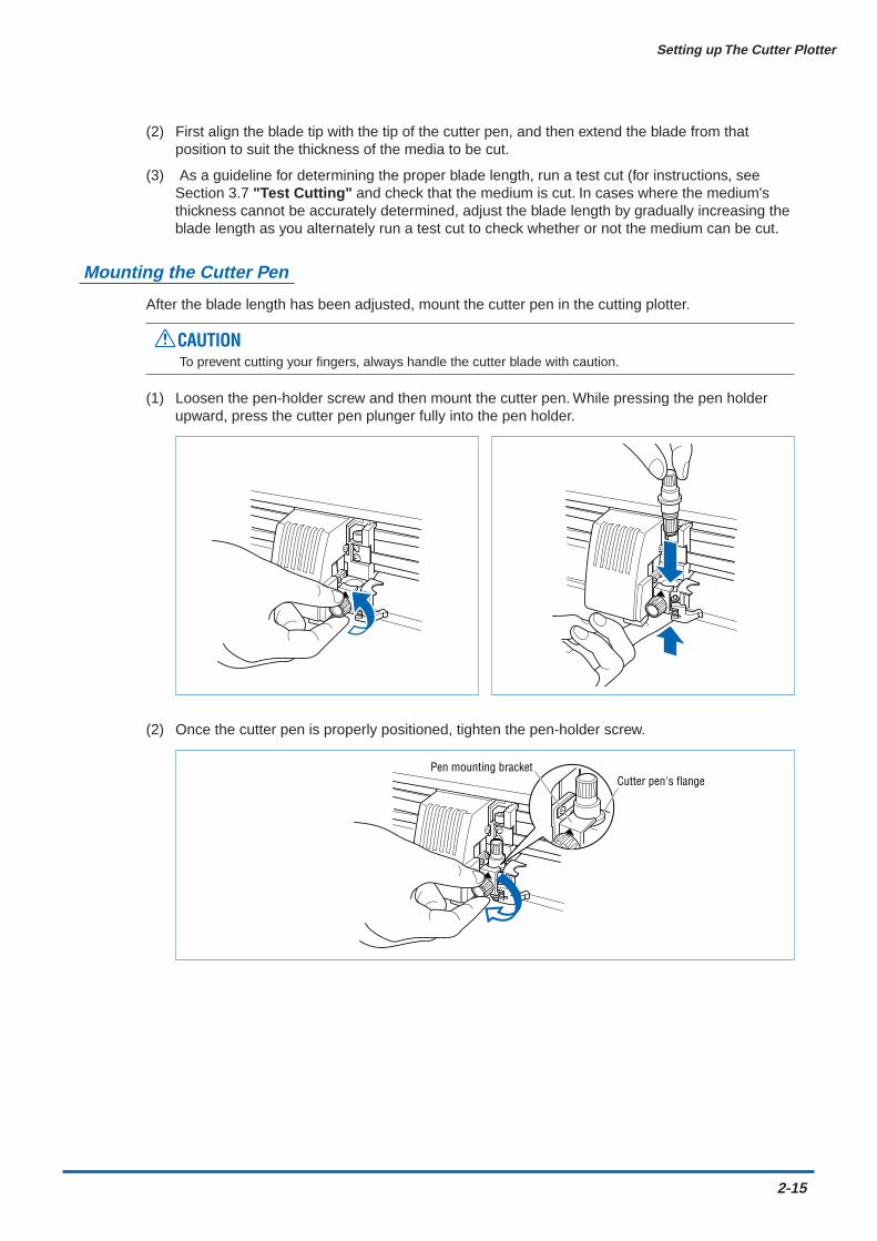
(1) Loosen the pen-holder screw and then mount the cutter pen. While pressing the pen holderupward, press the cutter pen plunger fully into the pen holder.
(2) Once the cutter pen is properly positioned, tighten the pen-holder screw.
Cutter pen's flangePen mounting bracket
2-16
Setting up The Cutter Plotter
2.6 Mounting the Pen
Mount a pen in the pen station
CHECKPOINTWhen mounting a pen for this cutting plotter, be sure to mount it at the pen station. To avoid injury, avoid touchingthe pen immediately after the cutting plotter is turned on or whenever the pen is moving.
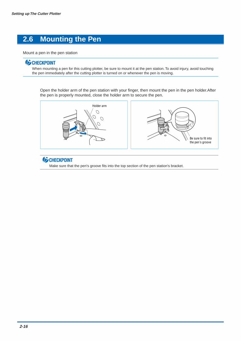
Open the holder arm of the pen station with your finger, then mount the pen in the pen holder.Afterthe pen is properly mounted, close the holder arm to secure the pen.
Holder arm
Be sure to fit into the pen's groove
CHECKPOINTMake sure that the pen's groove fits into the top section of the pen station's bracket.
CHAPTER 3Basic Settings and Operations
3.1 Setting the Cutter-Pen Conditions3.2 Displaying the Effective Cutting Area3.3 Moving the Pen3.4 Setting the Initial Cutting Position (Origin Point)3.5 Stop Function3.6 Moving the Pen Carriage in +100 mm Steps3.7 Test Cutting
3-2
Basic Settings and Operations
3.1 Setting the Cutter-Pen Conditions
Before starting cutting, set the TOOL (cutter blade or pen), cutter-blade length, OFFSET, FORCE, SPEED,and QUALITY settings to ensure the optimal cutting conditions.
TOOL (cutter blade or pen)........................ Set to suit the material to be cut.
Cutter-blade length ... Adjust the blade length by referring to the media thickness table below. Fordetails on adjusting the blade length, see "2.4 Adjusting and Mounting theCutter Pen."
OFFSET.................... Set to suit the cutter blade being used.
FORCE ..................... Set the FORCE by referring to the table below.
SPEED...................... Set the SPEED by referring to the table below.
QUALITY................... Set the QUALITY by referring to the table below.
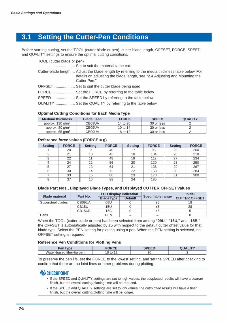
Optimal Cutting Conditions for Each Media Type
Reference force values (FORCE = g)
Blade Part Nos., Displayed Blade Types, and Displayed CUTTER OFFSET Values
When the TOOL (cutter blade or pen) has been selected from among "09U," "15U," and "15B,"the OFFSET is automatically adjusted by ±5 with respect to the default cutter offset value for thatblade type. Select the PEN setting for plotting using a pen. When the PEN setting is selected, noOFFSET setting is required.
Reference Pen Conditions for Plotting Pens
To preserve the pen life, set the FORCE to the lowest setting, and set the SPEED after checking toconfirm that there are no faint lines or other problems during plotting.
CHECKPOINT• If the SPEED and QUALITY settings are set to high values, the cut/plotted results will have a coarser
finish, but the overall cutting/plotting time will be reduced.
• If the SPEED and QUALITY settings are set to low values, the cut/plotted results will have a finerfinish, but the overall cutting/plotting time will be longer.
Medium thickness Blade used FORCE SPEED QUALITYapprox. 130 g/m2 CB09UA 14 to 20 30 or less 2
approx. 80 g/m2 CB09UA 10 to 14 30 or less 2approx. 65 g/m2 CB09UA 8 to 12 30 or less 2
Setting FORCE Setting FORCE Setting FORCE Setting FORCE1 20 9 40 17 96 25 2002 21 10 43 18 104 26 2183 22 11 48 19 112 27 2344 24 12 56 20 120 28 2505 27 13 64 21 136 29 2676 30 14 72 22 153 30 2847 33 15 80 23 170 31 3008 37 16 88 24 185
Blade material Part No.LCD display indication
Specifiable rangeInitial
Blade type Default CUTTER OFFSETSupersteel blades CB09UA 09U 0 ±5 18
CB15U 15U 0 ±5 28CB15UB 15B 0 ±5 5
Pens PEN – – 0
Pen type FORCE SPEED QUALITYWater-based fiber-tip pen 10 to 12 30 2
Basic Settings and Operations
3-3
Storing and Selecting Cutter Pen Condition Setting Areas
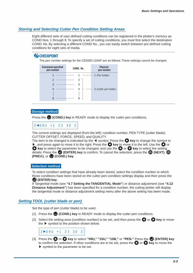
Eight different sets of user-defined cutting conditions can be registered in the plotter's memory asCOND Nos. 1 through 8. To specify a set of cutting conditions, you must first select the destinationCOND. No. By selecting a different COND No., you can easily switch between pre-defined cuttingconditions for eight sets of media.
CHECKPOINTThe pen number settings for the CE5000-120AP are as follows. These settings cannot be changed.
Command-specified pen number
1
2
3
4
8
COND. No.
1
2
3
4
8
Physical pen number
1 (Pen holder)
2 (Cutter pen holder)
Storage method
Press the (COND.) key in READY mode to display the cutter-pen conditions.
2 0 9 U + 1 2 3 3 0 2
The current settings are displayed (from the left): condition number, PEN TYPE (cutter blade),CUTTER OFFSET, FORCE, SPEED, and QUALITY.The item to be changed is indicated by the t symbol. Press the key to change the symbol tos, and press again to move it to the right. Press the key to move it to the left. Use the or
key to select the parameter to be changed, and use the or key to select the settingdetails. Press the (ENTER) key to confirm. To cancel the selection, press the (NEXT), (PREV.), or (COND.) key.
Selection method
To select condition settings that have already been stored, select the condition number to whichthose conditions have been stored on the cutter-pen-condition settings display and then press the
(ENTER) key.If Tangential mode (see "4.7 Setting the TANGENTIAL Mode") or distance adjustment (see "4.12Distance Adjustment") has been specified for a condition number, the cutting plotter will displaythe tangential mode or distance adjustment setting menu after the above setting has been made.
Setting TOOL (cutter blade or pen)
Set the type of pen (cutter blade) to be used.
(1) Press the (COND.) key in READY mode to display the cutter-pen conditions.
(2) Select the setting area (condition number) to be set, and then press the or key to movethe s symbol to the position shown below.
2 0 9 U + 1 2 3 3 0 2
(3) Press the or key to select "09U," "15U," "15B," or "PEN." Press the (ENTER) keyto confirm the selection. If other conditions are to be set, press the or key to move thes symbol to the parameter to be set.
3-4
Basic Settings and Operations
Setting OFFSET
This setting adjusts the offset of the cutter blade to suit the blade type used. The tip of the blademounted in the cutter-pen plunger is not positioned at the center of the pen, so correction isrequired. This correction is referred to as the OFFSET setting. The cutting plotter has been presetwith OFFSET values for each cutter-blade type. Selecting "09U," "15U," or "15B" for the PENTYPE setting also sets the appropriate OFFSET, allowing fine adjustment within the range of ±5.When the "PEN" setting is selected, the OFFSET cannot be set.
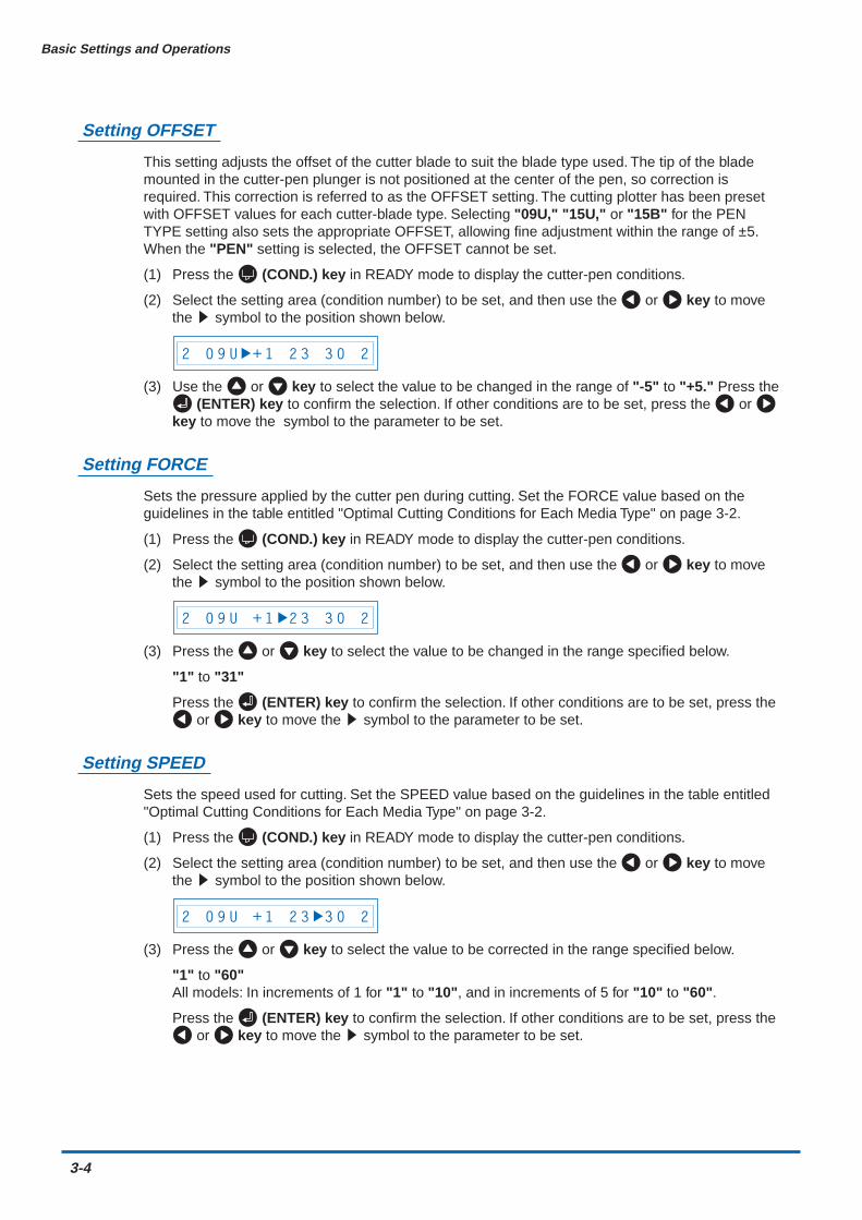
(1) Press the (COND.) key in READY mode to display the cutter-pen conditions.
(2) Select the setting area (condition number) to be set, and then use the or key to movethe s symbol to the position shown below.
2 0 9 U + 1 2 3 3 0 2
(3) Use the or key to select the value to be changed in the range of "-5" to "+5." Press the (ENTER) key to confirm the selection. If other conditions are to be set, press the or
key to move the symbol to the parameter to be set.
Setting FORCE
Sets the pressure applied by the cutter pen during cutting. Set the FORCE value based on theguidelines in the table entitled "Optimal Cutting Conditions for Each Media Type" on page 3-2.
(1) Press the (COND.) key in READY mode to display the cutter-pen conditions.
(2) Select the setting area (condition number) to be set, and then use the or key to movethe s symbol to the position shown below.
2 0 9 U + 1 2 3 3 0 2
(3) Press the or key to select the value to be changed in the range specified below.
"1" to "31"
Press the (ENTER) key to confirm the selection. If other conditions are to be set, press the or key to move the s symbol to the parameter to be set.
Setting SPEED
Sets the speed used for cutting. Set the SPEED value based on the guidelines in the table entitled"Optimal Cutting Conditions for Each Media Type" on page 3-2.
(1) Press the (COND.) key in READY mode to display the cutter-pen conditions.
(2) Select the setting area (condition number) to be set, and then use the or key to movethe s symbol to the position shown below.
2 0 9 U + 1 2 3 3 0 2
(3) Press the or key to select the value to be corrected in the range specified below.
"1" to "60"All models: In increments of 1 for "1" to "10", and in increments of 5 for "10" to "60".
Press the (ENTER) key to confirm the selection. If other conditions are to be set, press the or key to move the s symbol to the parameter to be set.
Basic Settings and Operations
3-5
Setting QUALITY
Sets the acceleration used in cutting.
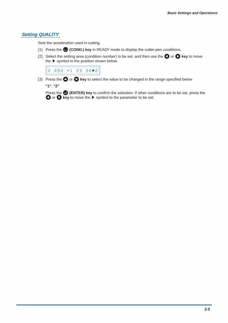
(1) Press the (COND.) key in READY mode to display the cutter-pen conditions.
(2) Select the setting area (condition number) to be set, and then use the or key to movethe s symbol to the position shown below.
2 0 9 U + 1 2 3 3 0 2
(3) Press the or key to select the value to be changed in the range specified below
"1", "2"
Press the (ENTER) key to confirm the selection. If other conditions are to be set, press the or key to move the s symbol to the parameter to be set.
3-6
Basic Settings and Operations
3.2 Displaying the Effective Cutting Area
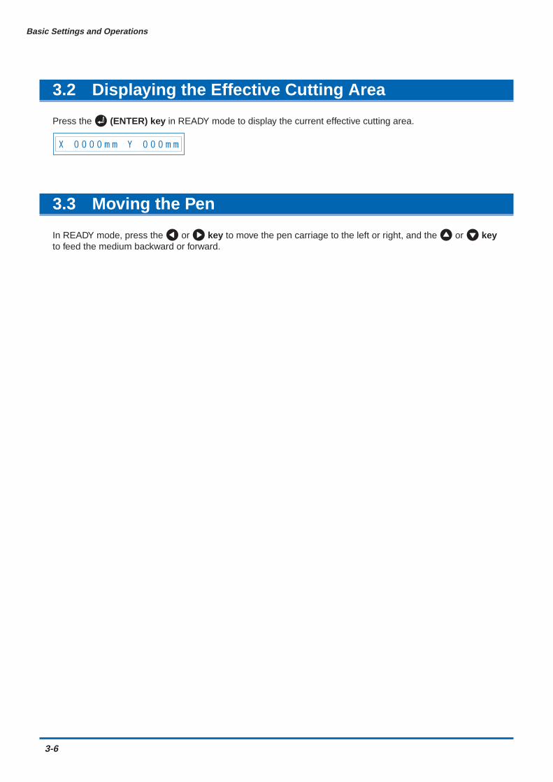
Press the (ENTER) key in READY mode to display the current effective cutting area.
X 0 0 0 0 m m Y 0 0 0 m m
3.3 Moving the Pen
In READY mode, press the or key to move the pen carriage to the left or right, and the or keyto feed the medium backward or forward.
Basic Settings and Operations
3-7
3.4 Setting the Initial Cutting Position (Origin Point)
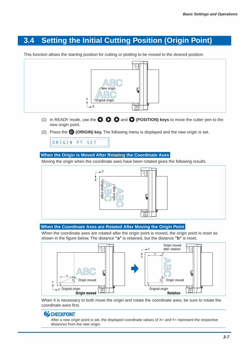
This function allows the starting position for cutting or plotting to be moved to the desired position.
Original origin
New origin
Y
X
(1) In READY mode, use the , , and (POSITION) keys to move the cutter pen to thenew origin point.
(2) Press the (ORIGIN) key. The following menu is displayed and the new origin is set.
O R I G I N P T S E T
When the Origin is Moved After Rotating the Coordinate AxesMoving the origin when the coordinate axes have been rotated gives the following results.
Original origin
New origin
X
Y
When the Coordinate Axes are Rotated After Moving the Origin PointWhen the coordinate axes are rotated after the origin point is moved, the origin point is reset asshown in the figure below. The distance "a" is retained, but the distance "b" is reset.
a
Origin moveda
b b
Origin moved after rotation
X
Y
Y
X Original origin
Origin moved
Original originOrigin moved Rotation
When it is necessary to both move the origin and rotate the coordinate axes, be sure to rotate thecoordinate axes first.
CHECKPOINTAfter a new origin point is set, the displayed coordinate values of X= and Y= represent the respectivedistances from the new origin.
3-8
Basic Settings and Operations
3.5 Stop Function
Cutting or plotting can be stopped by pressing the (PAUSE) key while cutting or plotting is in progress.Raising or lowering the media set lever while cutting or plotting is stopped does not require the medium to beselected, and so the medium can be replaced or reset.
If "PAUSE" has been specified at the "PAUSE key" Special Functions menu
(1) Press the (PAUSE) key while cutting or plotting is in progress to stop cutting or plotting anddisplay the PAUSE menu.
C O N T I N U E J O B
(2) Press he (NEXT) or (PREV.) key to alternate the display between "CONTINUE JOB"and "QUIT JOB".
C O N T I N U E J O B Q U I T J O B
(3) Pressing the (ENTER) key while "CONTINUE JOB" is displayed cancels the pausefunction and restarts cutting or plotting.
(4) Pressing the (ENTER) key while "QUIT JOB" is displayed displays the BUFFER CLEARconfirmation screen for aborting the cutting/plotting operation.
C L E A R < Y E S >
(5) Press the or key to alternate the display between "YES" or "NO". To abort the cutting/plotting operation, stop the transmission of data from the computer, select "YES", and thenpress the (ENTER) key. All the cutting/plotting data stored in the buffer is cleared and theplotter returns to Ready status.To cancel the aborting of the cutting/plotting operation, select "NO" and then press the (ENTER) key.The plotter returns to the "CONTINUE JOB" display.
If "MENU" has been specified at the "PAUSE key" Special Functions menuNote: This setting is the factory default setting
The PAUSE menu is displayed after operation has been stopped to enable the various settings tobe changed.
(1) Press the (PAUSE) key while cutting or plotting is in progress to stop cutting or plotting anddisplay the following menu.
(2) Change the PAUSE menu settings.
(3) Press the (PAUSE) key to cancel the PAUSE status and restart cutting or plotting.
Basic Settings and Operations
3-9
3.6 Moving the Pen Carriage in +100 mm Steps
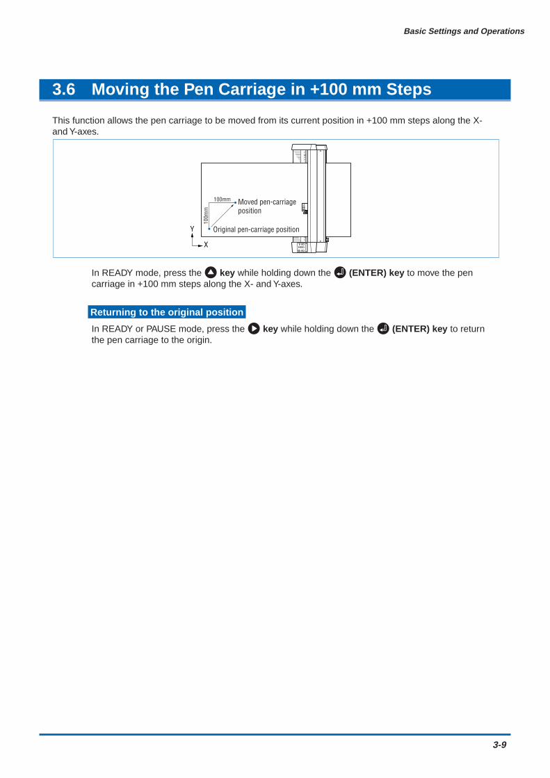
This function allows the pen carriage to be moved from its current position in +100 mm steps along the X-and Y-axes.
Y
X
Original pen-carriage position
Moved pen-carriageposition
100mm10
0mm
In READY mode, press the key while holding down the (ENTER) key to move the pencarriage in +100 mm steps along the X- and Y-axes.
Returning to the original position
In READY or PAUSE mode, press the key while holding down the (ENTER) key to returnthe pen carriage to the origin.
3-10
Basic Settings and Operations
3.7 Test Cutting
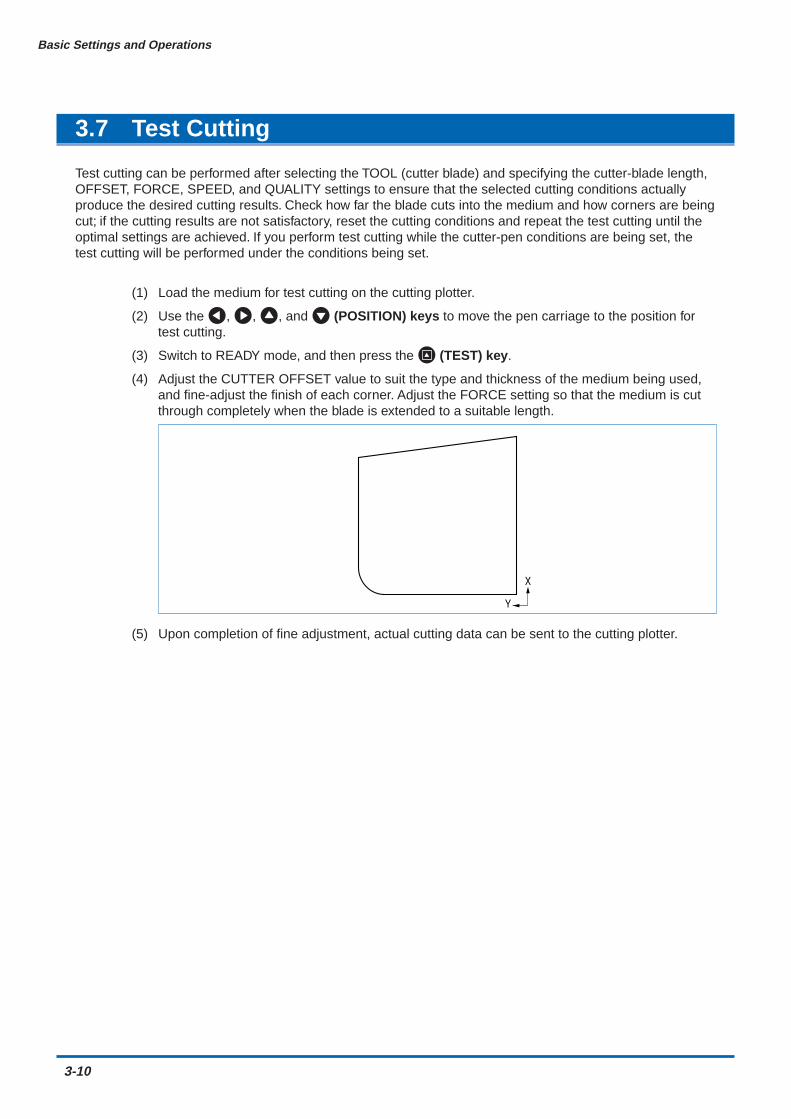
Test cutting can be performed after selecting the TOOL (cutter blade) and specifying the cutter-blade length,OFFSET, FORCE, SPEED, and QUALITY settings to ensure that the selected cutting conditions actuallyproduce the desired cutting results. Check how far the blade cuts into the medium and how corners are beingcut; if the cutting results are not satisfactory, reset the cutting conditions and repeat the test cutting until theoptimal settings are achieved. If you perform test cutting while the cutter-pen conditions are being set, thetest cutting will be performed under the conditions being set.
(1) Load the medium for test cutting on the cutting plotter.
(2) Use the , , , and (POSITION) keys to move the pen carriage to the position fortest cutting.
(3) Switch to READY mode, and then press the (TEST) key.
(4) Adjust the CUTTER OFFSET value to suit the type and thickness of the medium being used,and fine-adjust the finish of each corner. Adjust the FORCE setting so that the medium is cutthrough completely when the blade is extended to a suitable length.
X
Y
(5) Upon completion of fine adjustment, actual cutting data can be sent to the cutting plotter.
CHAPTER 4Function Settings and Operations
4.1 PAUSE Menu List4.2 Clearing the Buffer Memory4.3 Setting the FEED & CUT function4.4 Blade Wear Detection (When Blade Wear Setup is On)4.5 Raising and Lowering the Pen4.6 Selecting the Type of Perforated Line4.7 Setting TANGENTIAL Mode4.8 Selecting the Blade Tip's Initial Position4.9 Setting the PEN UP SPEED4.10 Specifying the INITIAL FEED Length4.11 Setting AUTO PRE-FEED4.12 Distance Adjustment4.13 Aligning the Coordinate Axes4.14 Setting the Cutting/Plotting Area4.15 Expanding the Cutting/Plotting Area4.16 Rotating the Coordinate Axes4.17 Sorting Settings4.18 Specifying the SPACE REAR Distance4.19 Setting the OFFSET FORCE (Initial Cutting Force)4.20 Setting the Initial Down Force4.21 Setting the STEP PASS4.22 Setting the OFFSET ANGLE4.23 Setting the F_CUT Function4.24 Setting the LENGTH UNIT4.25 Adjusting the Distance Between the Pens4.26 Cutting/Plotting Using the Buffer Memory (COPY Function)4.27 User-specified Settings4.28 Setting the Format of Data to be Received4.29 Interface Settings4.30 Setting the PAGE LENGTH4.31 Setting the SEPARATOR Function4.32 Setting the TIMEOUT Function4.33 Setting the PAPER READY TIME4.34 Setting the PAPER LOAD Function4.35 TEST Mode
4-2
Function Settings and Operations
4.1 PAUSE Menu List
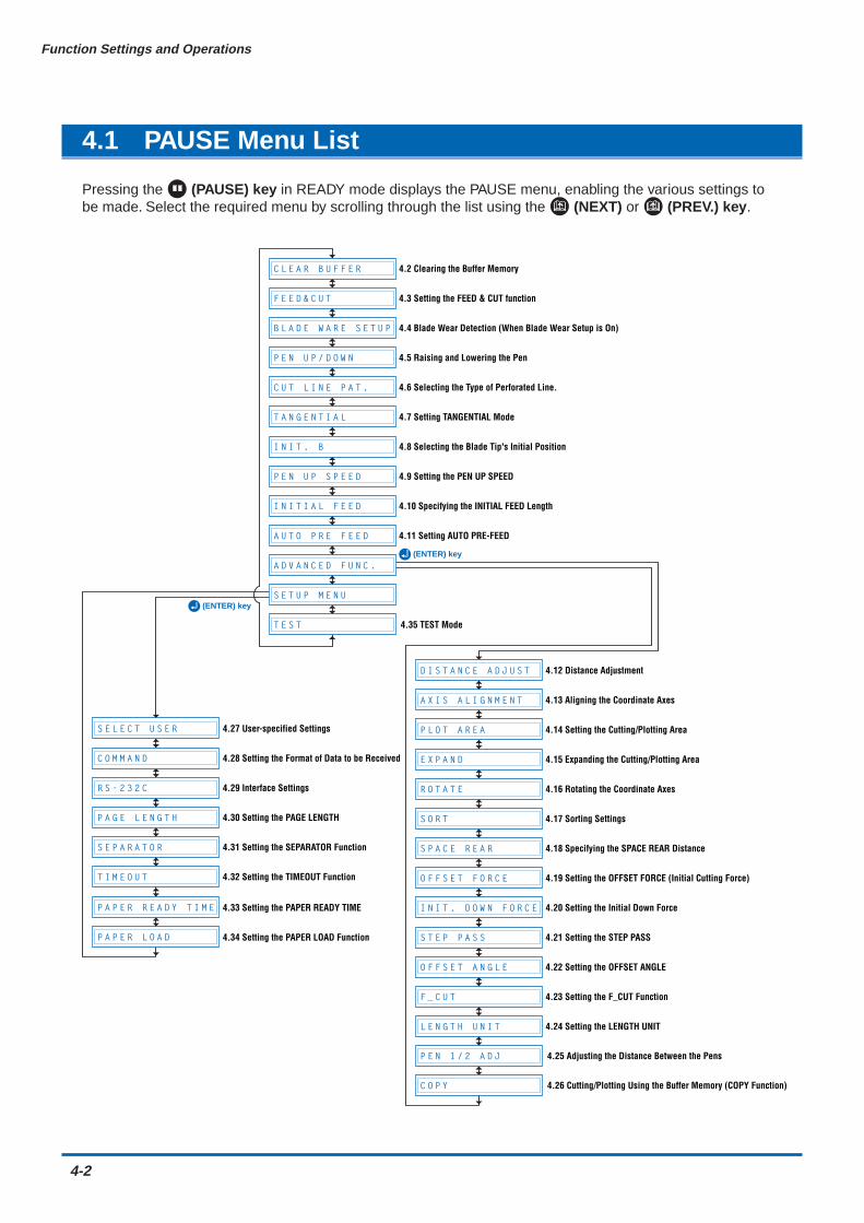
Pressing the (PAUSE) key in READY mode displays the PAUSE menu, enabling the various settings tobe made. Select the required menu by scrolling through the list using the (NEXT) or (PREV.) key.
S E L E C T U S E R
C O M M A N D
R S - 2 3 2 C
P A G E L E N G T H
S E P A R A T O R
T I M E O U T
P A P E R R E A D Y T I M E
P A P E R L O A D
C L E A R B U F F E R
D I S T A N C E A D J U S T
A X I S A L I G N M E N T
P L O T A R E A
E X P A N D
R O T A T E
S O R T
S P A C E R E A R
O F F S E T F O R C E
I N I T . D O W N F O R C E
S T E P P A S S
O F F S E T A N G L E
F _ C U T
L E N G T H U N I T
F E E D & C U T
B L A D E W A R E S E T U P
P E N U P / D O W N
C U T L I N E P A T .
T A N G E N T I A L
I N I T . B
P E N U P S P E E D
I N I T I A L F E E D
A U T O P R E F E E D
A D V A N C E D F U N C .
S E T U P M E N U
T E S T
P E N 1 / 2 A D J
C O P Y
4.2 Clearing the Buffer Memory
4.3 Setting the FEED & CUT function
4.4 Blade Wear Detection (When Blade Wear Setup is On)
4.5 Raising and Lowering the Pen
4.6 Selecting the Type of Perforated Line.
4.7 Setting TANGENTIAL Mode
4.8 Selecting the Blade Tip's Initial Position
4.9 Setting the PEN UP SPEED
4.10 Specifying the INITIAL FEED Length
4.11 Setting AUTO PRE-FEED
4.35 TEST Mode
4.25 Adjusting the Distance Between the Pens
4.26 Cutting/Plotting Using the Buffer Memory (COPY Function)
4.12 Distance Adjustment
4.27 User-specified Settings
4.28 Setting the Format of Data to be Received
4.29 Interface Settings
4.30 Setting the PAGE LENGTH
4.31 Setting the SEPARATOR Function
4.32 Setting the TIMEOUT Function
4.33 Setting the PAPER READY TIME
4.34 Setting the PAPER LOAD Function
4.13 Aligning the Coordinate Axes
4.14 Setting the Cutting/Plotting Area
4.15 Expanding the Cutting/Plotting Area
4.16 Rotating the Coordinate Axes
4.17 Sorting Settings
4.18 Specifying the SPACE REAR Distance
4.19 Setting the OFFSET FORCE (Initial Cutting Force)
4.20 Setting the Initial Down Force
4.21 Setting the STEP PASS
4.22 Setting the OFFSET ANGLE
4.23 Setting the F_CUT Function
4.24 Setting the LENGTH UNIT
(ENTER) key
(ENTER) key

Function Settings and Operations
4-3
4.2 Clearing the Buffer Memory
This function deletes the data sent to the cutting plotter. It is used to abort cutting while it is in progress.
(1) Press the (PAUSE) key to switch to PAUSE mode.
(2) Stop the transmission of data from the computer if this is in progress.
(3) Press the (NEXT) or (PREV.) key until the following menu is displayed.
C L E A R B U F F E R
(4) Press the (ENTER) key to display the clear-buffer-memory menu.
C L E A R < Y E S >
(5) Press the or key to select "YES" or "NO," and then press the (ENTER) key. To cancel the selection, select "NO" and press the (ENTER)key, or press the (NEXT) or (PREV.) key .
B L A D E W A R E S E T U P
C U T L I N E P A T .
T A N G E N T I A L
I N I T . B
P E N U P S P E E D
I N I T I A L F E E D
A U T O P R E F E E D
A D V A N C E D F U N C .
S E T U P M E N U
T E S T
F E E D & C U T
P E N U P / D O W N
C L E A R B U F F E R
4-4
Function Settings and Operations
4.3 Setting the FEED & CUT function
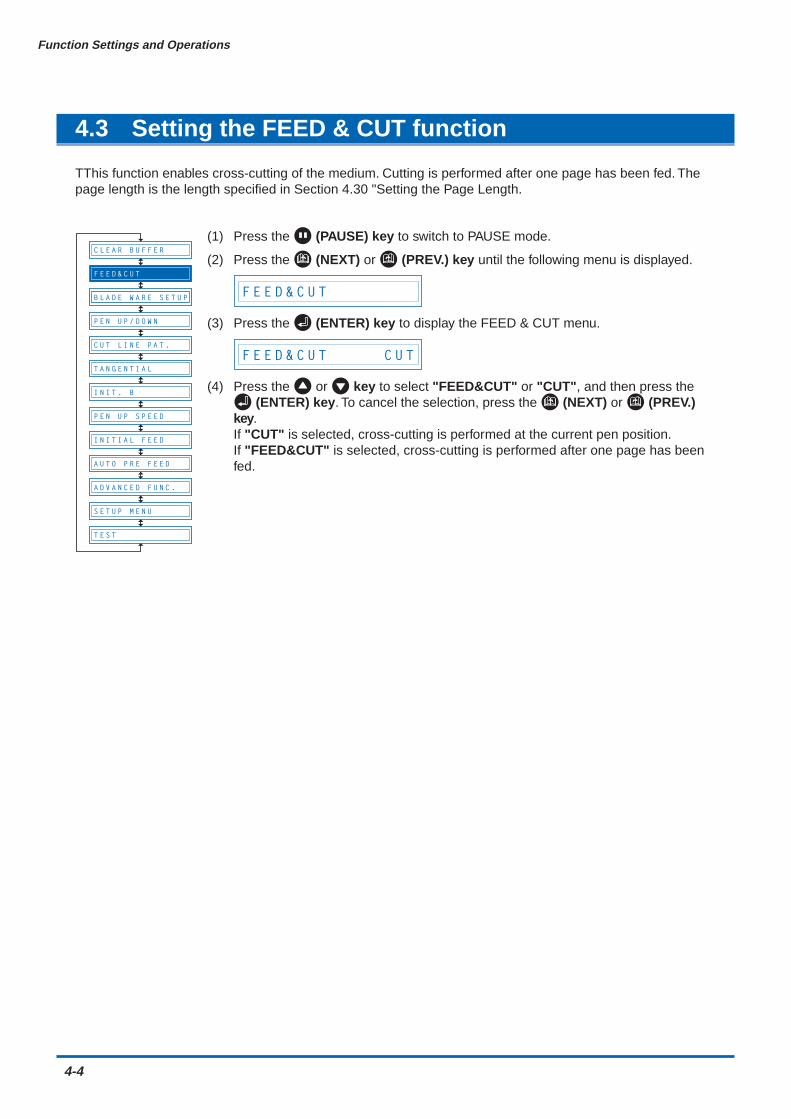
TThis function enables cross-cutting of the medium. Cutting is performed after one page has been fed. Thepage length is the length specified in Section 4.30 "Setting the Page Length.
(1) Press the (PAUSE) key to switch to PAUSE mode.
(2) Press the (NEXT) or (PREV.) key until the following menu is displayed.
F E E D & C U T
(3) Press the (ENTER) key to display the FEED & CUT menu.
F E E D & C U T C U T
(4) Press the or key to select "FEED&CUT" or "CUT", and then press the (ENTER) key. To cancel the selection, press the (NEXT) or (PREV.)
key.If "CUT" is selected, cross-cutting is performed at the current pen position.If "FEED&CUT" is selected, cross-cutting is performed after one page has beenfed.
B L A D E W A R E S E T U P
C U T L I N E P A T .
T A N G E N T I A L
I N I T . B
P E N U P S P E E D
I N I T I A L F E E D
A U T O P R E F E E D
A D V A N C E D F U N C .
S E T U P M E N U
T E S T
C L E A R B U F F E R
P E N U P / D O W N
F E E D & C U T
Function Settings and Operations
4-5
4.4 Blade Wear Detection (When Blade Wear Setup is On)
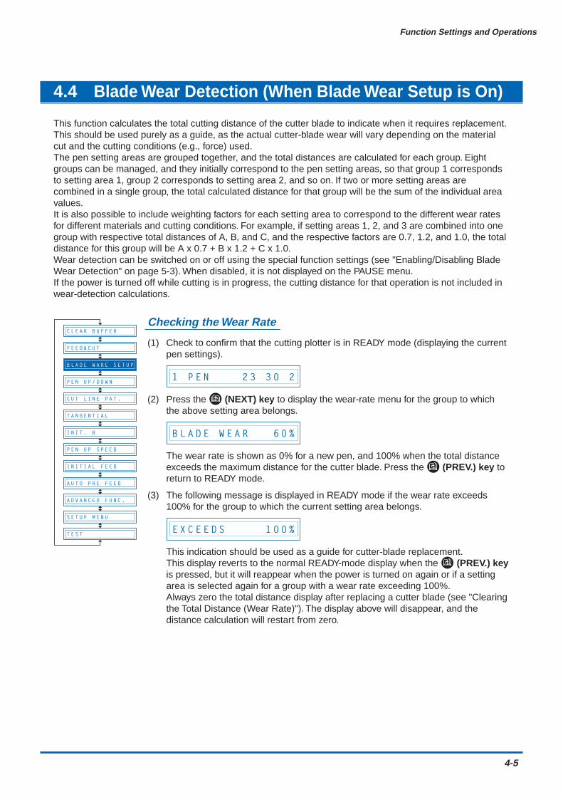
This function calculates the total cutting distance of the cutter blade to indicate when it requires replacement.This should be used purely as a guide, as the actual cutter-blade wear will vary depending on the materialcut and the cutting conditions (e.g., force) used.The pen setting areas are grouped together, and the total distances are calculated for each group. Eightgroups can be managed, and they initially correspond to the pen setting areas, so that group 1 correspondsto setting area 1, group 2 corresponds to setting area 2, and so on. If two or more setting areas arecombined in a single group, the total calculated distance for that group will be the sum of the individual areavalues.It is also possible to include weighting factors for each setting area to correspond to the different wear ratesfor different materials and cutting conditions. For example, if setting areas 1, 2, and 3 are combined into onegroup with respective total distances of A, B, and C, and the respective factors are 0.7, 1.2, and 1.0, the totaldistance for this group will be A x 0.7 + B x 1.2 + C x 1.0.Wear detection can be switched on or off using the special function settings (see "Enabling/Disabling BladeWear Detection" on page 5-3). When disabled, it is not displayed on the PAUSE menu.If the power is turned off while cutting is in progress, the cutting distance for that operation is not included inwear-detection calculations.
Checking the Wear Rate
(1) Check to confirm that the cutting plotter is in READY mode (displaying the currentpen settings).
1 P E N 2 3 3 0 2
(2) Press the (NEXT) key to display the wear-rate menu for the group to whichthe above setting area belongs.
B L A D E W E A R 6 0 %
The wear rate is shown as 0% for a new pen, and 100% when the total distanceexceeds the maximum distance for the cutter blade. Press the (PREV.) key toreturn to READY mode.
(3) The following message is displayed in READY mode if the wear rate exceeds100% for the group to which the current setting area belongs.
E X C E E D S 1 0 0 %
This indication should be used as a guide for cutter-blade replacement.This display reverts to the normal READY-mode display when the (PREV.) keyis pressed, but it will reappear when the power is turned on again or if a settingarea is selected again for a group with a wear rate exceeding 100%.Always zero the total distance display after replacing a cutter blade (see "Clearingthe Total Distance (Wear Rate)"). The display above will disappear, and thedistance calculation will restart from zero.
B L A D E W A R E S E T U P
C U T L I N E P A T .
T A N G E N T I A L
I N I T . B
P E N U P S P E E D
I N I T I A L F E E D
A U T O P R E F E E D
A D V A N C E D F U N C .
S E T U P M E N U
T E S T
P E N U P / D O W N
F E E D & C U T
C L E A R B U F F E R
4-6
Function Settings and Operations
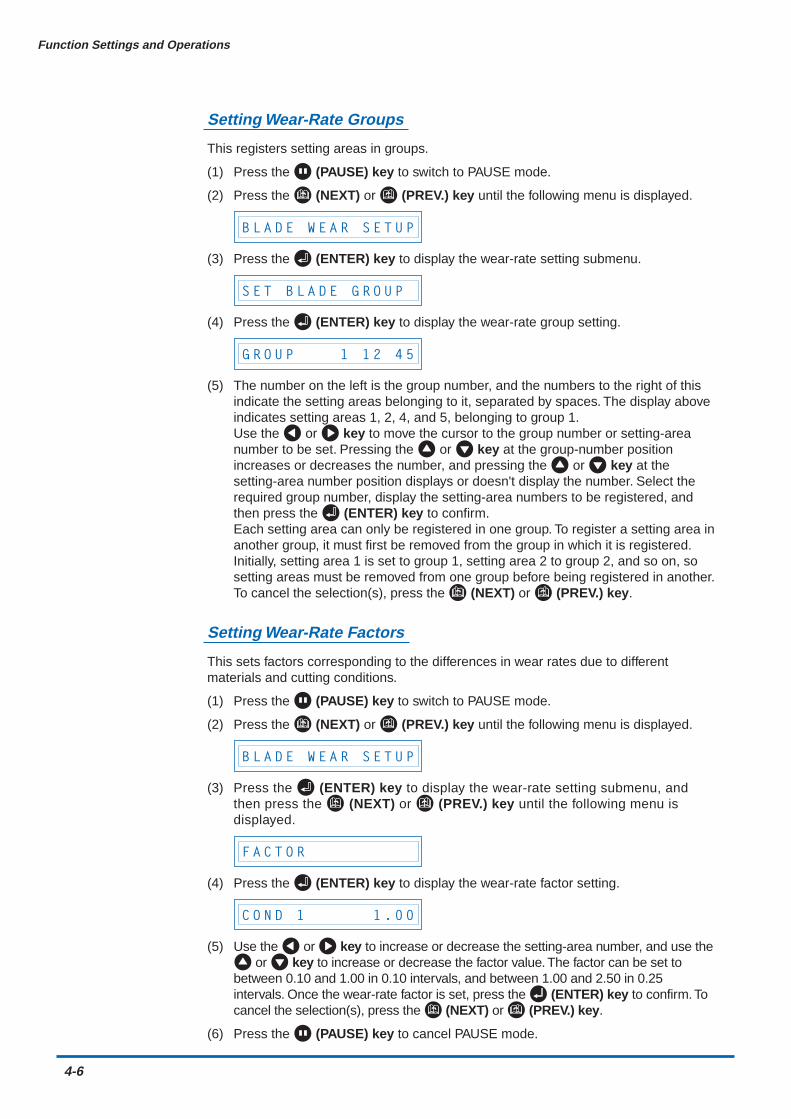
Setting Wear-Rate Groups
This registers setting areas in groups.
(1) Press the (PAUSE) key to switch to PAUSE mode.
(2) Press the (NEXT) or (PREV.) key until the following menu is displayed.
B L A D E W E A R S E T U P
(3) Press the (ENTER) key to display the wear-rate setting submenu.
S E T B L A D E G R O U P
(4) Press the (ENTER) key to display the wear-rate group setting.
G R O U P 1 1 2 4 5
(5) The number on the left is the group number, and the numbers to the right of thisindicate the setting areas belonging to it, separated by spaces. The display aboveindicates setting areas 1, 2, 4, and 5, belonging to group 1.Use the or key to move the cursor to the group number or setting-areanumber to be set. Pressing the or key at the group-number positionincreases or decreases the number, and pressing the or key at thesetting-area number position displays or doesn't display the number. Select therequired group number, display the setting-area numbers to be registered, andthen press the (ENTER) key to confirm.Each setting area can only be registered in one group. To register a setting area inanother group, it must first be removed from the group in which it is registered.Initially, setting area 1 is set to group 1, setting area 2 to group 2, and so on, sosetting areas must be removed from one group before being registered in another.To cancel the selection(s), press the (NEXT) or (PREV.) key.
Setting Wear-Rate Factors
This sets factors corresponding to the differences in wear rates due to differentmaterials and cutting conditions.
(1) Press the (PAUSE) key to switch to PAUSE mode.
(2) Press the (NEXT) or (PREV.) key until the following menu is displayed.
B L A D E W E A R S E T U P
(3) Press the (ENTER) key to display the wear-rate setting submenu, andthen press the (NEXT) or (PREV.) key until the following menu isdisplayed.
F A C T O R
(4) Press the (ENTER) key to display the wear-rate factor setting.
C O N D 1 1 . 0 0
(5) Use the or key to increase or decrease the setting-area number, and use the or key to increase or decrease the factor value. The factor can be set to
between 0.10 and 1.00 in 0.10 intervals, and between 1.00 and 2.50 in 0.25intervals. Once the wear-rate factor is set, press the (ENTER) key to confirm. Tocancel the selection(s), press the (NEXT) or (PREV.) key.
(6) Press the (PAUSE) key to cancel PAUSE mode.
Function Settings and Operations
4-7
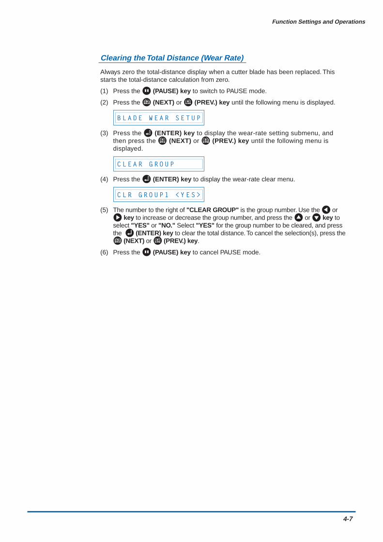
Clearing the Total Distance (Wear Rate)
Always zero the total-distance display when a cutter blade has been replaced. Thisstarts the total-distance calculation from zero.
(1) Press the (PAUSE) key to switch to PAUSE mode.
(2) Press the (NEXT) or (PREV.) key until the following menu is displayed.
B L A D E W E A R S E T U P
(3) Press the (ENTER) key to display the wear-rate setting submenu, andthen press the (NEXT) or (PREV.) key until the following menu isdisplayed.
C L E A R G R O U P
(4) Press the (ENTER) key to display the wear-rate clear menu.
C L R G R O U P 1 < Y E S >
(5) The number to the right of "CLEAR GROUP" is the group number. Use the or key to increase or decrease the group number, and press the or key to
select "YES" or "NO." Select "YES" for the group number to be cleared, and pressthe (ENTER) key to clear the total distance. To cancel the selection(s), press the
(NEXT) or (PREV.) key.
(6) Press the (PAUSE) key to cancel PAUSE mode.
4-8
Function Settings and Operations
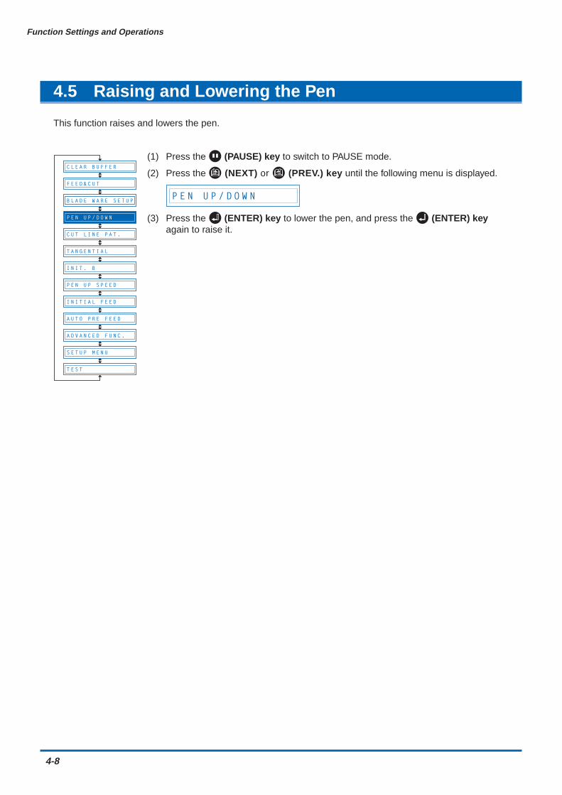
4.5 Raising and Lowering the Pen
This function raises and lowers the pen.
(1) Press the (PAUSE) key to switch to PAUSE mode.
(2) Press the (NEXT) or (PREV.) key until the following menu is displayed.
P E N U P / D O W N
(3) Press the (ENTER) key to lower the pen, and press the (ENTER) keyagain to raise it.
B L A D E W A R E S E T U P
C U T L I N E P A T .
T A N G E N T I A L
I N I T . B
P E N U P S P E E D
I N I T I A L F E E D
A U T O P R E F E E D
A D V A N C E D F U N C .
S E T U P M E N U
T E S T
P E N U P / D O W N
F E E D & C U T
C L E A R B U F F E R

Function Settings and Operations
4-9
4.6 Selecting the Type of Perforated Line
The CUT LINE PAT. function lets you specify one of seven types of cut lines from 0 to 6. If you select OFF, asolid line is cut. The default setting is 6. Change this setting if the shapes being cut either separate too easilyor are hard to separate.Using this function, you can select the cut line pattern ratio (the ratio of cut segments to uncut segments ineach line) by specifying the LINE TYPE NO. The smaller the value, the shorter the uncut segments and theeasier it is for cut shapes to be separated. When the specified LINE TYPE NO. properly suits the medium youare using, cut shapes can be easily separated after cutting but will not come loose during cutting.
(1) Press the (PAUSE) key to switch to PAUSE mode.
(2) Press the (NEXT) or (PREV.) key until the following menu is displayed.
C U T L I N E P A T .
(3) Press the (ENTER) key to display the PERF. LINE TYPE setting.
L I N E T Y P E N O O F F
(4) Press the or key to select "OFF" or a value within the range "0" to" 6,"and then press the (ENTER) key. To cancel the selection, press the (NEXT) or (PREV.) key.
(5) Press the (PAUSE) key to cancel PAUSE mode.
CHECKPOINTThe setting is retained in the internal memory even when the power is turned off.
B L A D E W A R E S E T U P
T A N G E N T I A L
I N I T . B
P E N U P S P E E D
I N I T I A L F E E D
A U T O P R E F E E D
A D V A N C E D F U N C .
S E T U P M E N U
T E S T
F E E D & C U T
C L E A R B U F F E R
P E N U P / D O W N
C U T L I N E P A T .
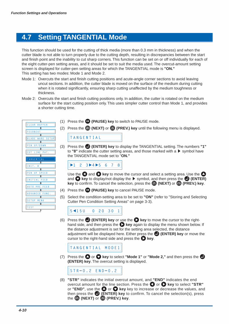
4-10
Function Settings and Operations
4.7 Setting TANGENTIAL Mode
This function should be used for the cutting of thick media (more than 0.3 mm in thickness) and when thecutter blade is not able to turn properly due to the cutting depth, resulting in discrepancies between the startand finish point and the inability to cut sharp corners. This function can be set on or off individually for each ofthe eight cutter-pen setting areas, and it should be set to suit the media used. The overcut-amount settingscreen is displayed for cutter-pen setting areas for which the TANGENTIAL mode is "ON."This setting has two modes: Mode 1 and Mode 2.
Mode 1: Overcuts the start and finish cutting positions and acute-angle corner sections to avoid leavinguncut sections. In addition, the cutter blade is moved on the surface of the medium during cuttingwhen it is rotated significantly, ensuring sharp cutting unaffected by the medium toughness orthickness.
Mode 2: Overcuts the start and finish cutting positions only. In addition, the cutter is rotated on the mediumsurface for the start cutting position only. This uses simpler cutter control than Mode 1, and providesa shorter cutting time.
(1) Press the (PAUSE) key to switch to PAUSE mode.
(2) Press the (NEXT) or (PREV.) key until the following menu is displayed.
T A N G E N T I A L
(3) Press the (ENTER) key to display the TANGENTIAL setting. The numbers "1"to "8" indicate the cutter setting areas, and those marked with a s symbol havethe TANGENTIAL mode set to "ON."
1 2 3 4 5 6 7 8
Use the and key to move the cursor and select a setting area. Use the and key to display/not display the s symbol, and then press the (ENTER)key to confirm. To cancel the selection, press the (NEXT) or (PREV.) key.
(4) Press the (PAUSE) key to cancel PAUSE mode.
(5) Select the condition-setting area to be set to "ON" (refer to "Storing and SelectingCutter Pen Condition Setting Areas" on page 3-3).
5 1 5 U 0 2 0 3 0 1
(6) Press the (ENTER) key or use the key to move the cursor to the right-hand side, and then press the key again to display the menu shown below. Ifthe distance adjustment is set for the setting area selected, the distanceadjustment will be displayed here. Either press the (ENTER) key or move thecursor to the right-hand side and press the key.
T A N G E N T I A L M O D E 1
(7) Press the or key to select "Mode 1" or "Mode 2," and then press the (ENTER) key. The overcut setting is displayed.
S T R = 0 . 2 E N D = 0 . 2
(8) "STR" indicates the initial overcut amount, and "END" indicates the endovercut amount for the line section. Press the or key to select "STR"or "END", use the or key key to increase or decrease the values, andthen press the (ENTER) key to confirm. To cancel the selection(s), pressthe (NEXT) or (PREV.) key.
B L A D E W A R E S E T U P
C U T L I N E P A T .
I N I T . B
P E N U P S P E E D
I N I T I A L F E E D
A U T O P R E F E E D
A D V A N C E D F U N C .
S E T U P M E N U
T E S T
F E E D & C U T
C L E A R B U F F E R
P E N U P / D O W N
T A N G E N T I A L
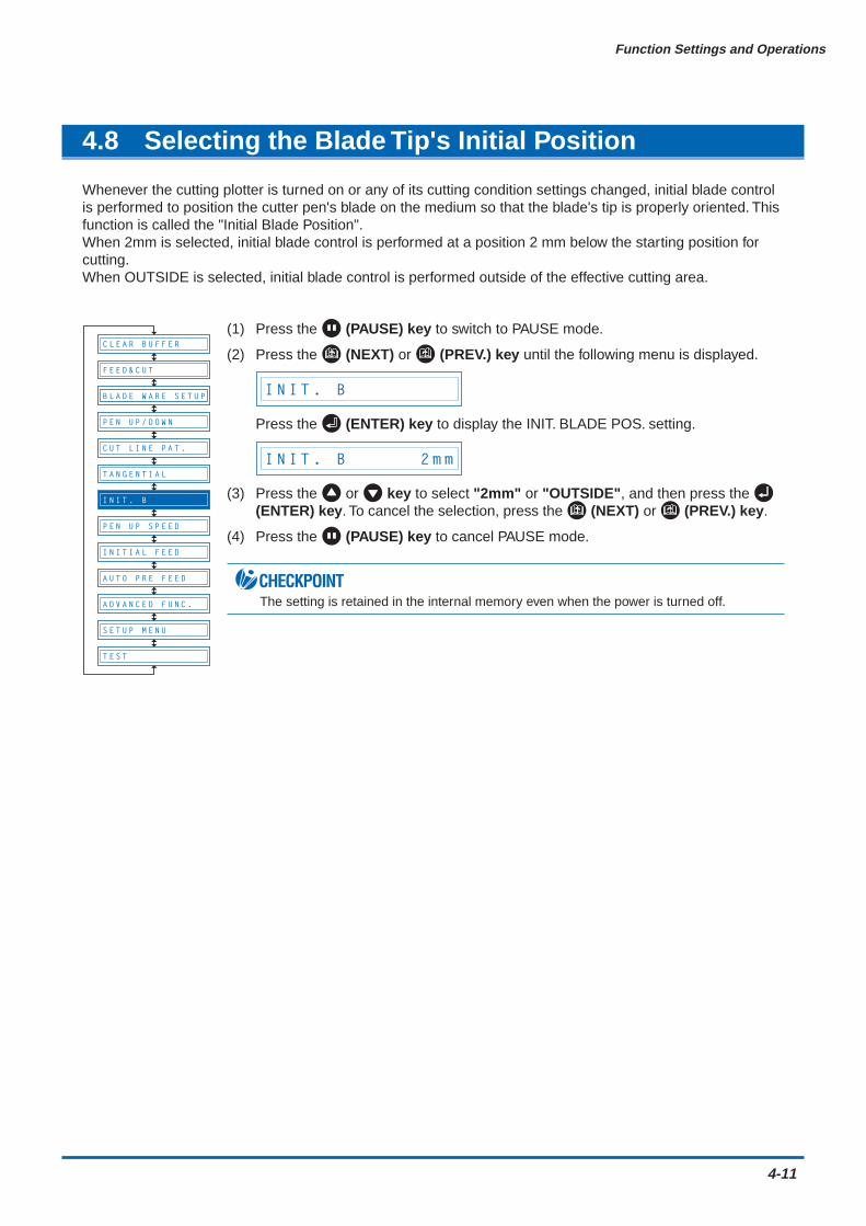
Function Settings and Operations
4-11
4.8 Selecting the Blade Tip's Initial Position
Whenever the cutting plotter is turned on or any of its cutting condition settings changed, initial blade controlis performed to position the cutter pen's blade on the medium so that the blade's tip is properly oriented. Thisfunction is called the "Initial Blade Position".When 2mm is selected, initial blade control is performed at a position 2 mm below the starting position forcutting.When OUTSIDE is selected, initial blade control is performed outside of the effective cutting area.
(1) Press the (PAUSE) key to switch to PAUSE mode.
(2) Press the (NEXT) or (PREV.) key until the following menu is displayed.
I N I T . B
Press the (ENTER) key to display the INIT. BLADE POS. setting.
I N I T . B 2 m m
(3) Press the or key to select "2mm" or "OUTSIDE", and then press the (ENTER) key. To cancel the selection, press the (NEXT) or (PREV.) key.
(4) Press the (PAUSE) key to cancel PAUSE mode.
CHECKPOINTThe setting is retained in the internal memory even when the power is turned off.
B L A D E W A R E S E T U P
C U T L I N E P A T .
T A N G E N T I A L
P E N U P S P E E D
I N I T I A L F E E D
A U T O P R E F E E D
A D V A N C E D F U N C .
S E T U P M E N U
T E S T
F E E D & C U T
C L E A R B U F F E R
P E N U P / D O W N
I N I T . B

4-12
Function Settings and Operations
4.9 Setting the PEN UP SPEED
This function sets the travel speed of the pen when it is raised. It can be specified independently of thecutting SPEED function. When the PEN UP SPEED is high, the pen travels faster when it is raised, therebyreducing the overall cutting time. Your cutting plotter comes with its PEN UP SPEED set to AUTO, whichselects the same speed as the cutting SPEED function (pen lowered). If long-axis cutting is performed with ahigh PEN UP SPEED setting, the medium is susceptible to becoming caught up.
(1) Press the (PAUSE) key to switch to PAUSE mode.
(2) Press the (NEXT) or (PREV.) key until the following menu is displayed.
P E N U P S P E E D
(3) Press the (ENTER) key to display the pen-up-speed menu.
U P S P E E D = A U T O
Use the or key to select the value to be set, and then press the (ENTER) key to confirm.
"AUTO" "30" "40" "50" "60" cm/s
To cancel the selection, press the (NEXT) or (PREV.) key.
(4) Press the (PAUSE) key to cancel PAUSE mode.
CHECKPOINTThis setting is retained in the internal memory even when the power is turned off.
B L A D E W A R E S E T U P
C U T L I N E P A T .
T A N G E N T I A L
I N I T . B
I N I T I A L F E E D
A U T O P R E F E E D
A D V A N C E D F U N C .
S E T U P M E N U
T E S T
F E E D & C U T
C L E A R B U F F E R
P E N U P / D O W N
P E N U P S P E E D
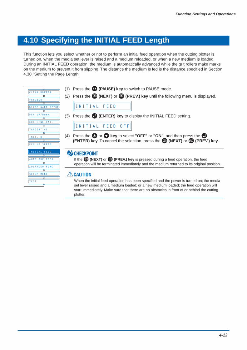
Function Settings and Operations
4-13
4.10 Specifying the INITIAL FEED Length
This function lets you select whether or not to perform an initial feed operation when the cutting plotter isturned on, when the media set lever is raised and a medium reloaded, or when a new medium is loaded.During an INITIAL FEED operation, the medium is automatically advanced while the grit rollers make markson the medium to prevent it from slipping. The distance the medium is fed is the distance specified in Section4.30 "Setting the Page Length.
(1) Press the (PAUSE) key to switch to PAUSE mode.
(2) Press the (NEXT) or (PREV.) key until the following menu is displayed.
I N I T I A L F E E D
(3) Press the (ENTER) key to display the INITIAL FEED setting.
I N I T I A L F E E D O F F
(4) Press the or key to select "OFF" or "ON", and then press the (ENTER) key. To cancel the selection, press the (NEXT) or (PREV.) key.
CHECKPOINTIf the (NEXT) or (PREV.) key is pressed during a feed operation, the feedoperation will be terminated immediately and the medium returned to its original position.
CAUTIONWhen the initial feed operation has been specified and the power is turned on; the mediaset lever raised and a medium loaded; or a new medium loaded; the feed operation willstart immediately. Make sure that there are no obstacles in front of or behind the cuttingplotter.
B L A D E W A R E S E T U P
C U T L I N E P A T .
T A N G E N T I A L
I N I T . B
P E N U P S P E E D
A U T O P R E F E E D
A D V A N C E D F U N C .
S E T U P M E N U
T E S T
F E E D & C U T
C L E A R B U F F E R
P E N U P / D O W N
I N I T I A L F E E D
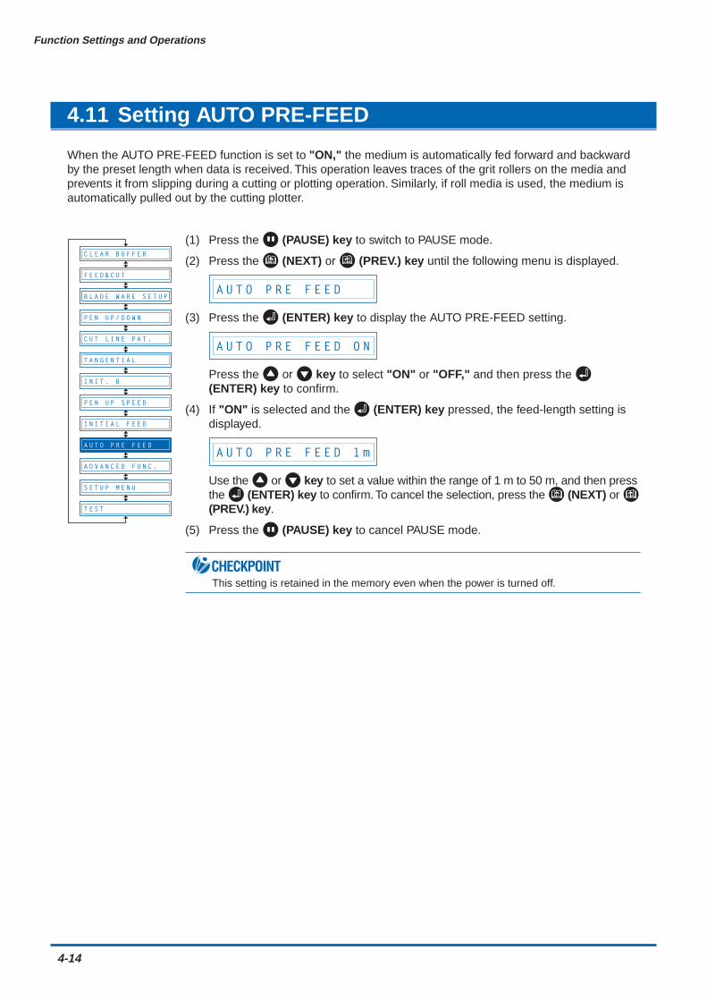
4-14
Function Settings and Operations
4.11 Setting AUTO PRE-FEED
When the AUTO PRE-FEED function is set to "ON," the medium is automatically fed forward and backwardby the preset length when data is received. This operation leaves traces of the grit rollers on the media andprevents it from slipping during a cutting or plotting operation. Similarly, if roll media is used, the medium isautomatically pulled out by the cutting plotter.
(1) Press the (PAUSE) key to switch to PAUSE mode.
(2) Press the (NEXT) or (PREV.) key until the following menu is displayed.
A U T O P R E F E E D
(3) Press the (ENTER) key to display the AUTO PRE-FEED setting.
A U T O P R E F E E D O N
Press the or key to select "ON" or "OFF," and then press the (ENTER) key to confirm.
(4) If "ON" is selected and the (ENTER) key pressed, the feed-length setting isdisplayed.
A U T O P R E F E E D 1 m
Use the or key to set a value within the range of 1 m to 50 m, and then pressthe (ENTER) key to confirm. To cancel the selection, press the (NEXT) or (PREV.) key.
(5) Press the (PAUSE) key to cancel PAUSE mode.
CHECKPOINTThis setting is retained in the memory even when the power is turned off.
B L A D E W A R E S E T U P
C U T L I N E P A T .
T A N G E N T I A L
I N I T . B
P E N U P S P E E D
I N I T I A L F E E D
A D V A N C E D F U N C .
S E T U P M E N U
T E S T
F E E D & C U T
P E N U P / D O W N
A U T O P R E F E E D
C L E A R B U F F E R
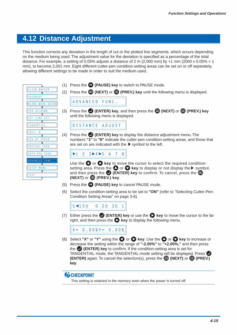
Function Settings and Operations
4-15
4.12 Distance Adjustment
This function corrects any deviation in the length of cut or the plotted line segments, which occurs dependingon the medium being used. The adjustment value for the deviation is specified as a percentage of the totaldistance. For example, a setting of 0.05% adjusts a distance of 2 m (2,000 mm) by +1 mm (2000 x 0.05% = 1mm), to become 2,001 mm. Eight different cutter-pen condition-setting areas can be set on or off separately,allowing different settings to be made in order to suit the medium used.
(1) Press the (PAUSE) key to switch to PAUSE mode.
(2) Press the (NEXT) or (PREV.) key until the following menu is displayed.
A D V A N C E D F U N C .
(3) Press the (ENTER) key, and then press the (NEXT) or (PREV.) keyuntil the following menu is displayed.
D I S T A N C E A D J U S T
(4) Press the (ENTER) key to display the distance adjustment menu. Thenumbers "1" to "8" indicate the cutter-pen condition-setting areas, and those thatare set on are indicated with the ssymbol to the left.
1 2 3 4 5 6 7 8
Use the or key to move the cursor to select the required condition-setting area. Press the or key to display or not display thes symbol,and then press the (ENTER) key to confirm. To cancel, press the (NEXT) or (PREV.) key.
(5) Press the (PAUSE) key to cancel PAUSE mode.
(6) Select the condition-setting area to be set to "ON" (refer to "Selecting Cutter-Pen-Condition Setting Areas" on page 3-6).
5 1 5 U 0 2 0 3 0 1
(7) Either press the (ENTER) key or use the key to move the cursor to the farright, and then press the key to display the following menu.
X = 0 . 0 0 % Y = 0 . 0 0 %
(8) Select "X" or "Y" using the or key. Use the or key to increase ordecrease the setting within the range of "-2.00%" to "+2.00%," and then pressthe (ENTER) key to confirm. If the condition-setting area is set forTANGENTIAL mode, the TANGENTIAL-mode setting will be displayed. Press (ENTER) again. To cancel the selection(s), press the (NEXT) or (PREV.)key.
CHECKPOINTThis setting is retained in the memory even when the power is turned off.
B L A D E W A R E S E T U P
C U T L I N E P A T .
T A N G E N T I A L
I N I T . B
P E N U P S P E E D
I N I T I A L F E E D
A U T O P R E F E E D
S E T U P M E N U
T E S T
F E E D & C U T
P E N U P / D O W N
A D V A N C E D F U N C .
C L E A R B U F F E R
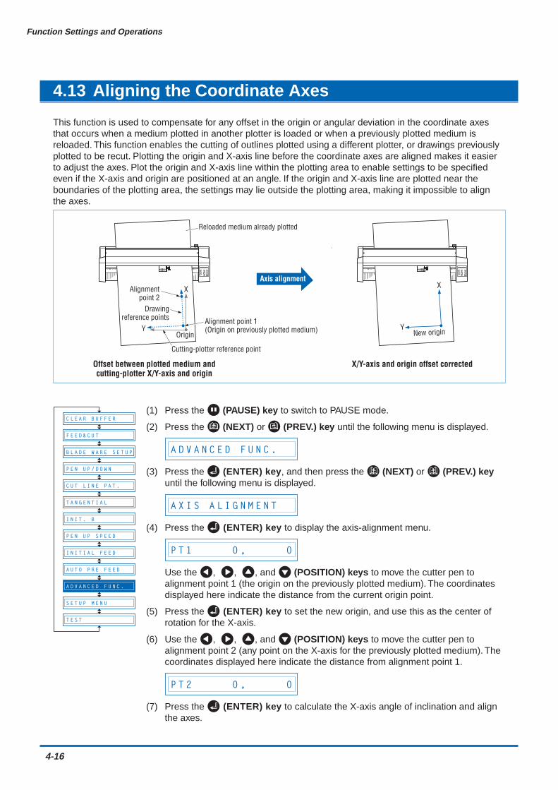
4-16
Function Settings and Operations
4.13 Aligning the Coordinate Axes
This function is used to compensate for any offset in the origin or angular deviation in the coordinate axesthat occurs when a medium plotted in another plotter is loaded or when a previously plotted medium isreloaded. This function enables the cutting of outlines plotted using a different plotter, or drawings previouslyplotted to be recut. Plotting the origin and X-axis line before the coordinate axes are aligned makes it easierto adjust the axes. Plot the origin and X-axis line within the plotting area to enable settings to be specifiedeven if the X-axis and origin are positioned at an angle. If the origin and X-axis line are plotted near theboundaries of the plotting area, the settings may lie outside the plotting area, making it impossible to alignthe axes.
Offset between plotted medium andcutting-plotter X/Y-axis and origin
X/Y-axis and origin offset corrected
Axis alignment
Origin
X
YAlignment point 1 (Origin on previously plotted medium)
Cutting-plotter reference point
Reloaded medium already plotted
Alignmentpoint 2
Drawingreference points
New origin
X
Y
(1) Press the (PAUSE) key to switch to PAUSE mode.
(2) Press the (NEXT) or (PREV.) key until the following menu is displayed.
A D V A N C E D F U N C .
(3) Press the (ENTER) key, and then press the (NEXT) or (PREV.) keyuntil the following menu is displayed.
A X I S A L I G N M E N T
(4) Press the (ENTER) key to display the axis-alignment menu.
P T 1 0 , 0
Use the , , , and (POSITION) keys to move the cutter pen toalignment point 1 (the origin on the previously plotted medium). The coordinatesdisplayed here indicate the distance from the current origin point.
(5) Press the (ENTER) key to set the new origin, and use this as the center ofrotation for the X-axis.
(6) Use the , , , and (POSITION) keys to move the cutter pen toalignment point 2 (any point on the X-axis for the previously plotted medium). Thecoordinates displayed here indicate the distance from alignment point 1.
P T 2 0 , 0
(7) Press the (ENTER) key to calculate the X-axis angle of inclination and alignthe axes.
B L A D E W A R E S E T U P
C U T L I N E P A T .
T A N G E N T I A L
I N I T . B
P E N U P S P E E D
I N I T I A L F E E D
A U T O P R E F E E D
S E T U P M E N U
T E S T
F E E D & C U T
P E N U P / D O W N
A D V A N C E D F U N C .
C L E A R B U F F E R

Function Settings and Operations
4-17
(8) Press the (PAUSE) key to cancel PAUSE mode.
CHECKPOINTAfter the axes are aligned, the settings will be reset if any of the following are performed.• Specification of a new origin• Loading of a new medium• Setting of the axis rotation
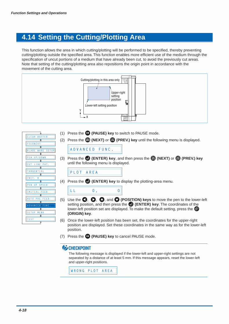
4-18
Function Settings and Operations
4.14 Setting the Cutting/Plotting Area
This function allows the area in which cutting/plotting will be performed to be specified, thereby preventingcutting/plotting outside the specified area. This function enables more efficient use of the medium through thespecification of uncut portions of a medium that have already been cut, to avoid the previously cut areas.Note that setting of the cutting/plotting area also repositions the origin point in accordance with themovement of the cutting area.
Lower-left setting position
Upper-rightsettingposition
Cutting/plotting in this area only
Y
X
(1) Press the (PAUSE) key to switch to PAUSE mode.
(2) Press the (NEXT) or (PREV.) key until the following menu is displayed.
A D V A N C E D F U N C .
(3) Press the (ENTER) key, and then press the (NEXT) or (PREV.) keyuntil the following menu is displayed.
P L O T A R E A
(4) Press the (ENTER) key to display the plotting-area menu.
L L 0 , 0
(5) Use the , , , and (POSITION) keys to move the pen to the lower-leftsetting position, and then press the (ENTER) key. The coordinates of thelower-left position set are displayed. To make the default setting, press the (ORIGIN) key.
(6) Once the lower-left position has been set, the coordinates for the upper-rightposition are displayed. Set these coordinates in the same way as for the lower-leftposition.
(7) Press the (PAUSE) key to cancel PAUSE mode.
CHECKPOINTThe following message is displayed if the lower-left and upper-right settings are notseparated by a distance of at least 5 mm. If this message appears, reset the lower-leftand upper-right positions.
W R O N G P L O T A R E A
BL A D E W A R E S E T U P
C U T L I N E P A T .
T A N G E N T I A L
I N I T . B
P E N U P S P E E D
I N I T I A L F E E D
A U T O P R E F E E D
S E T U P M E N U
T E S T
F E E D & C U T
P E N U P / D O W N
A D V A N C E D F U N C .
C L E A R B U F F E R

Function Settings and Operations
4-19
4.15 Expanding the Cutting/Plotting Area
This function allows the width of the cutting/plotting area to be extended by 9.5 mm on both sides, for a totalincrease of 19 mm, enabling cutting to be performed up to the area in which the pinch rollers are positioned.
(1) Press the (PAUSE) key to switch to PAUSE mode.
(2) Press the (NEXT) or (PREV.) key until the following menu is displayed.
A D V A N C E D F U N C .
(3) Press the (ENTER) key, and then press the (NEXT) or (PREV.) keyuntil the following menu is displayed.
E X P A N D
(4) Press the (ENTER) key to display the plotting-area width-setting menu.
E X P A N D O F F
Press the or key to select "ON" or "OFF," and then press the (ENTER) key to confirm. To cancel the selection, press the (NEXT) or (PREV.) key.
(5) If the settings are not changed, press the (PAUSE) key to cancel PAUSEmode. If the settings are changed, the media-type selection menu is displayed.
R O L L 2 P R E S S E N T R
(6) For details on the media loading and selection procedures, refer to "2.3 Loadingthe Medium."
CHECKPOINTThis setting is retained in the memory even when the power is turned off.
B L A D E W A R E S E T U P
C U T L I N E P A T .
T A N G E N T I A L
I N I T . B
P E N U P S P E E D
I N I T I A L F E E D
A U T O P R E F E E D
S E T U P M E N U
T E S T
F E E D & C U T
P E N U P / D O W N
A D V A N C E D F U N C .
C L E A R B U F F E R
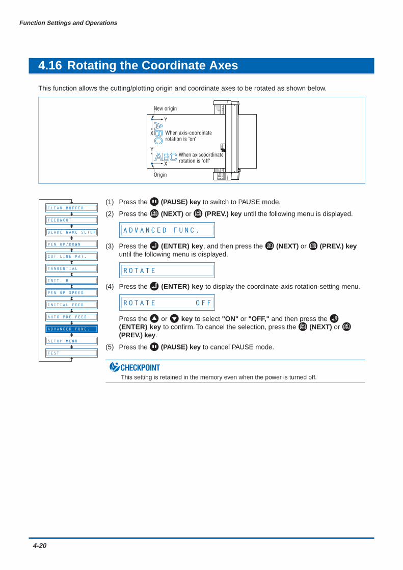
4-20
Function Settings and Operations
4.16 Rotating the Coordinate Axes
This function allows the cutting/plotting origin and coordinate axes to be rotated as shown below.
New origin
When axiscoordinaterotation is "off"
When axis-coordinaterotation is "on"
X
Y
Y
X
Origin
(1) Press the (PAUSE) key to switch to PAUSE mode.
(2) Press the (NEXT) or (PREV.) key until the following menu is displayed.
A D V A N C E D F U N C .
(3) Press the (ENTER) key, and then press the (NEXT) or (PREV.) keyuntil the following menu is displayed.
R O T A T E
(4) Press the (ENTER) key to display the coordinate-axis rotation-setting menu.
R O T A T E O F F
Press the or key to select "ON" or "OFF," and then press the (ENTER) key to confirm. To cancel the selection, press the (NEXT) or (PREV.) key.
(5) Press the (PAUSE) key to cancel PAUSE mode.
CHECKPOINTThis setting is retained in the memory even when the power is turned off.
B L A D E W A R E S E T U P
C U T L I N E P A T .
T A N G E N T I A L
I N I T . B
P E N U P S P E E D
I N I T I A L F E E D
A U T O P R E F E E D
S E T U P M E N U
T E S T
F E E D & C U T
P E N U P / D O W N
A D V A N C E D F U N C .
C L E A R B U F F E R
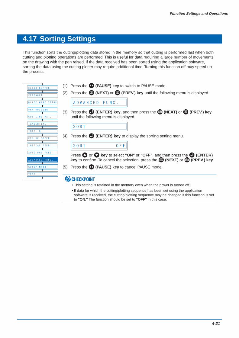
Function Settings and Operations
4-21
4.17 Sorting Settings
This function sorts the cutting/plotting data stored in the memory so that cutting is performed last when bothcutting and plotting operations are performed. This is useful for data requiring a large number of movementson the drawing with the pen raised. If the data received has been sorted using the application software,sorting the data using the cutting plotter may require additional time. Turning this function off may speed upthe process.
(1) Press the (PAUSE) key to switch to PAUSE mode.
(2) Press the (NEXT) or (PREV.) key until the following menu is displayed.
A D V A N C E D F U N C .
(3) Press the (ENTER) key, and then press the (NEXT) or (PREV.) keyuntil the following menu is displayed.
S O R T
(4) Press the (ENTER) key to display the sorting setting menu.
S O R T O F F
Press or key to select "ON" or "OFF", and then press the (ENTER)key to confirm. To cancel the selection, press the (NEXT) or (PREV.) key.
(5) Press the (PAUSE) key to cancel PAUSE mode.
CHECKPOINT• This setting is retained in the memory even when the power is turned off.
• If data for which the cutting/plotting sequence has been set using the applicationsoftware is received, the cutting/plotting sequence may be changed if this function is setto "ON." The function should be set to "OFF" in this case.
B L A D E W A R E S E T U P
C U T L I N E P A T .
T A N G E N T I A L
I N I T . B
P E N U P S P E E D
I N I T I A L F E E D
A U T O P R E F E E D
S E T U P M E N U
T E S T
F E E D & C U T
P E N U P / D O W N
A D V A N C E D F U N C .
C L E A R B U F F E R
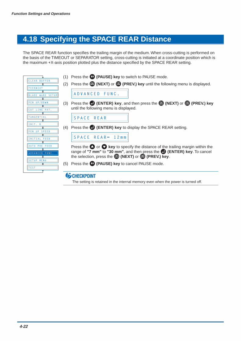
4-22
Function Settings and Operations
4.18 Specifying the SPACE REAR Distance
The SPACE REAR function specifies the trailing margin of the medium. When cross-cutting is performed onthe basis of the TIMEOUT or SEPARATOR setting, cross-cutting is initiated at a coordinate position which isthe maximum +X-axis position plotted plus the distance specified by the SPACE REAR setting.
(1) Press the (PAUSE) key to switch to PAUSE mode.
(2) Press the (NEXT) or (PREV.) key until the following menu is displayed.
A D V A N C E D F U N C .
(3) Press the (ENTER) key, and then press the (NEXT) or (PREV.) keyuntil the following menu is displayed.
S P A C E R E A R
(4) Press the (ENTER) key to display the SPACE REAR setting.
S P A C E R E A R = 1 2 m m
Press the or key to specify the distance of the trailing margin within therange of "7 mm" to "30 mm", and then press the (ENTER) key. To cancelthe selection, press the (NEXT) or (PREV.) key.
(5) Press the (PAUSE) key to cancel PAUSE mode.
CHECKPOINTThe setting is retained in the internal memory even when the power is turned off.
B L A D E W A R E S E T U P
C U T L I N E P A T .
T A N G E N T I A L
I N I T . B
P E N U P S P E E D
I N I T I A L F E E D
A U T O P R E F E E D
S E T U P M E N U
T E S T
F E E D & C U T
P E N U P / D O W N
A D V A N C E D F U N C .
C L E A R B U F F E R
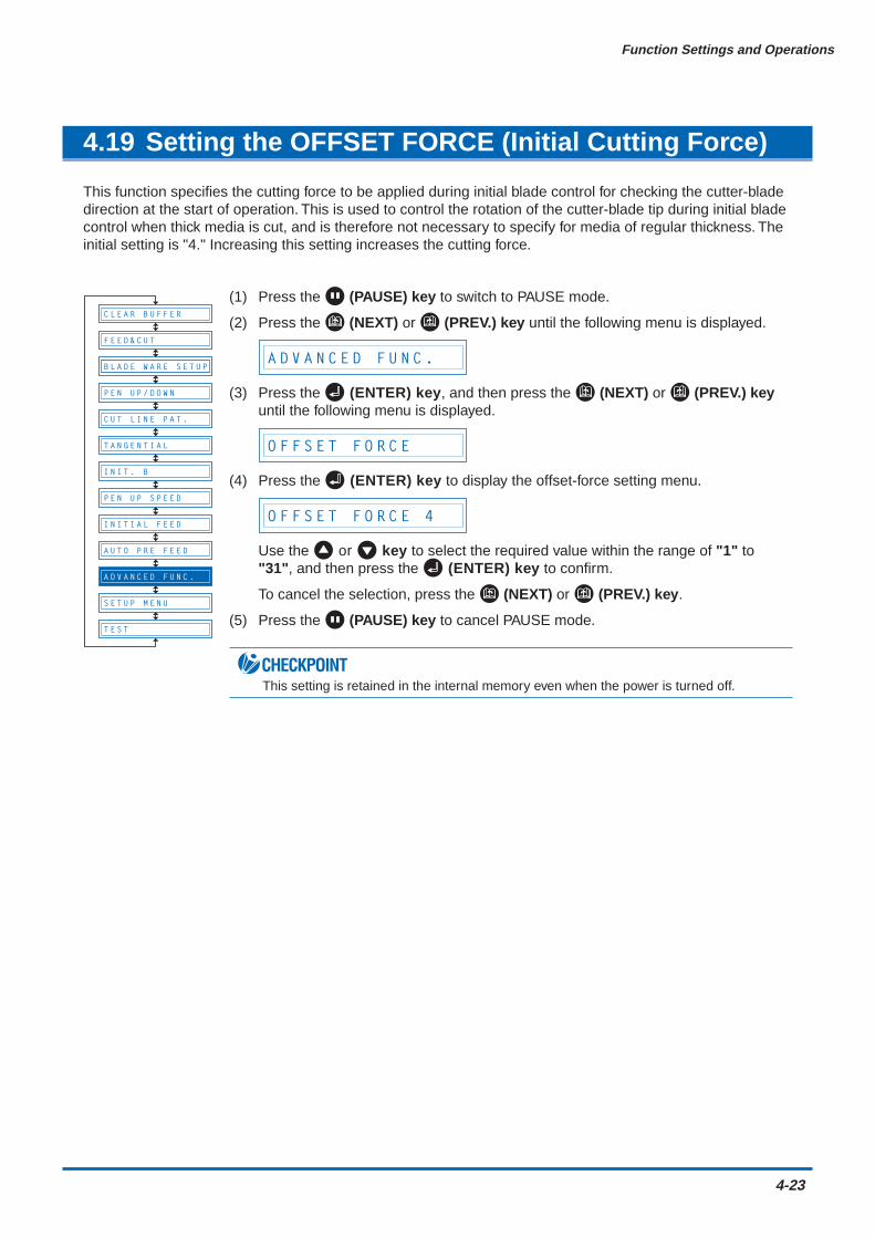
Function Settings and Operations
4-23
4.19 Setting the OFFSET FORCE (Initial Cutting Force)
This function specifies the cutting force to be applied during initial blade control for checking the cutter-bladedirection at the start of operation. This is used to control the rotation of the cutter-blade tip during initial bladecontrol when thick media is cut, and is therefore not necessary to specify for media of regular thickness. Theinitial setting is "4." Increasing this setting increases the cutting force.
(1) Press the (PAUSE) key to switch to PAUSE mode.
(2) Press the (NEXT) or (PREV.) key until the following menu is displayed.
A D V A N C E D F U N C .
(3) Press the (ENTER) key, and then press the (NEXT) or (PREV.) keyuntil the following menu is displayed.
O F F S E T F O R C E
(4) Press the (ENTER) key to display the offset-force setting menu.
O F F S E T F O R C E 4
Use the or key to select the required value within the range of "1" to"31", and then press the (ENTER) key to confirm.
To cancel the selection, press the (NEXT) or (PREV.) key.
(5) Press the (PAUSE) key to cancel PAUSE mode.
CHECKPOINTThis setting is retained in the internal memory even when the power is turned off.
B L A D E W A R E S E T U P
C U T L I N E P A T .
T A N G E N T I A L
I N I T . B
P E N U P S P E E D
I N I T I A L F E E D
A U T O P R E F E E D
S E T U P M E N U
T E S T
F E E D & C U T
P E N U P / D O W N
A D V A N C E D F U N C .
C L E A R B U F F E R

4-24
Function Settings and Operations
4.20 Setting the Initial Down Force
The initial down-force setting is useful when TANGENTIAL mode is selected (for the cutting of thick media).With a thick medium, additional time is required for the cutter blade to penetrate the medium fully, even whenthe necessary cutting force is applied. The cutting operation starts before the cutter blade has fullypenetrated the medium, causing uncut sections to be left. When the initial down force is specified, this forceis used as the cutting force immediately after lowering of the pen when TANGENTIAL mode is selected,enabling the cutter blade to penetrate the medium rapidly. (If the cutting force is 25 and the initial down forceis 4, for example, the cutting force applied immediately after lowering of the pen will be 29.) Set the initialdown force to suit the type of medium used by performing test cuts.
(1) Press the (PAUSE) key to switch to PAUSE mode.
(2) Press the (NEXT) or (PREV.) key until the following menu is displayed.
A D V A N C E D F U N C .
(3) Press the (ENTER) key, and then press the (NEXT) or (PREV.) keyuntil the following menu is displayed.
I N I T . D O W N F O R C E
(4) Press the (ENTER) key to display the initial-cutting-force setting menu.
I N I T . D O W N F . 0
Use the or key to select the required value within the range of "0" to"20," and then press the (ENTER) key to confirm. To cancel the selection,press the (NEXT) or (PREV.) key.
(5) Press the (PAUSE) key to cancel PAUSE mode.
CHECKPOINTThe setting is retained in the internal memory even when the power is turned off.
B L A D E W A R E S E T U P
C U T L I N E P A T .
T A N G E N T I A L
I N I T . B
P E N U P S P E E D
I N I T I A L F E E D
A U T O P R E F E E D
S E T U P M E N U
T E S T
F E E D & C U T
P E N U P / D O W N
A D V A N C E D F U N C .
C L E A R B U F F E R
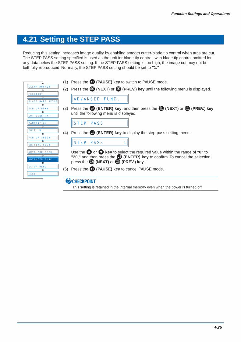
Function Settings and Operations
4-25
4.21 Setting the STEP PASS
Reducing this setting increases image quality by enabling smooth cutter-blade tip control when arcs are cut.The STEP PASS setting specified is used as the unit for blade tip control, with blade tip control omitted forany data below the STEP PASS setting. If the STEP PASS setting is too high, the image cut may not befaithfully reproduced. Normally, the STEP PASS setting should be set to "1."
(1) Press the (PAUSE) key to switch to PAUSE mode.
(2) Press the (NEXT) or (PREV.) key until the following menu is displayed.
A D V A N C E D F U N C .
(3) Press the (ENTER) key, and then press the (NEXT) or (PREV.) keyuntil the following menu is displayed.
S T E P P A S S
(4) Press the (ENTER) key to display the step-pass setting menu.
S T E P P A S S 1
Use the or key to select the required value within the range of "0" to"20," and then press the (ENTER) key to confirm. To cancel the selection,press the (NEXT) or (PREV.) key.
(5) Press the (PAUSE) key to cancel PAUSE mode.
CHECKPOINTThis setting is retained in the internal memory even when the power is turned off.
B L A D E W A R E S E T U P
C U T L I N E P A T .
T A N G E N T I A L
I N I T . B
P E N U P S P E E D
I N I T I A L F E E D
A U T O P R E F E E D
S E T U P M E N U
T E S T
F E E D & C U T
P E N U P / D O W N
A D V A N C E D F U N C .
C L E A R B U F F E R
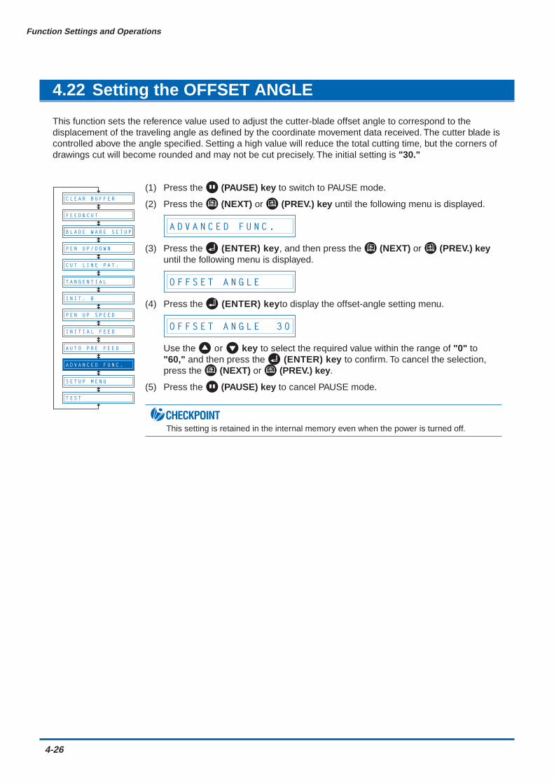
4-26
Function Settings and Operations
4.22 Setting the OFFSET ANGLE
This function sets the reference value used to adjust the cutter-blade offset angle to correspond to thedisplacement of the traveling angle as defined by the coordinate movement data received. The cutter blade iscontrolled above the angle specified. Setting a high value will reduce the total cutting time, but the corners ofdrawings cut will become rounded and may not be cut precisely. The initial setting is "30."
(1) Press the (PAUSE) key to switch to PAUSE mode.
(2) Press the (NEXT) or (PREV.) key until the following menu is displayed.
A D V A N C E D F U N C .
(3) Press the (ENTER) key, and then press the (NEXT) or (PREV.) keyuntil the following menu is displayed.
O F F S E T A N G L E
(4) Press the (ENTER) keyto display the offset-angle setting menu.
O F F S E T A N G L E 3 0
Use the or key to select the required value within the range of "0" to"60," and then press the (ENTER) key to confirm. To cancel the selection,press the (NEXT) or (PREV.) key.
(5) Press the (PAUSE) key to cancel PAUSE mode.
CHECKPOINTThis setting is retained in the internal memory even when the power is turned off.
B L A D E W A R E S E T U P
C U T L I N E P A T .
T A N G E N T I A L
I N I T . B
P E N U P S P E E D
I N I T I A L F E E D
A U T O P R E F E E D
S E T U P M E N U
T E S T
F E E D & C U T
P E N U P / D O W N
A D V A N C E D F U N C .
C L E A R B U F F E R

Function Settings and Operations
4-27
4.23 Setting the F_CUT Function
When the COMMAND setting is GP-GL, the F_CUT function is used to enable or disable cross-cutting. Whenthe F_CUT function is enabled, cross-cutting of the medium will be performed even if the cutting plotter issent a feed command instructing it not to cut the medium.
(1) Press the (PAUSE) key to switch to PAUSE mode.
(2) Press the (NEXT) or (PREV.) key until the following menu is displayed.
A D V A N C E D F U N C .
(3) Press the (ENTER) key, and then press the (NEXT) or (PREV.) keyuntil the following menu is displayed.
F _ C U T
(4) Press the (ENTER) key to display the F_CUT setting.
F _ C U T O N
Press the or key to specify "ON" or "OFF", and then press the (ENTER) key. To cancel the selection, press the (NEXT) or (PREV.) key.
(5) Press the (PAUSE) key to cancel PAUSE mode.
CHECKPOINTThe setting is retained in the internal memory even when the power is turned off.
B L A D E W A R E S E T U P
C U T L I N E P A T .
T A N G E N T I A L
I N I T . B
P E N U P S P E E D
I N I T I A L F E E D
A U T O P R E F E E D
S E T U P M E N U
T E S T
F E E D & C U T
P E N U P / D O W N
A D V A N C E D F U N C .
C L E A R B U F F E R
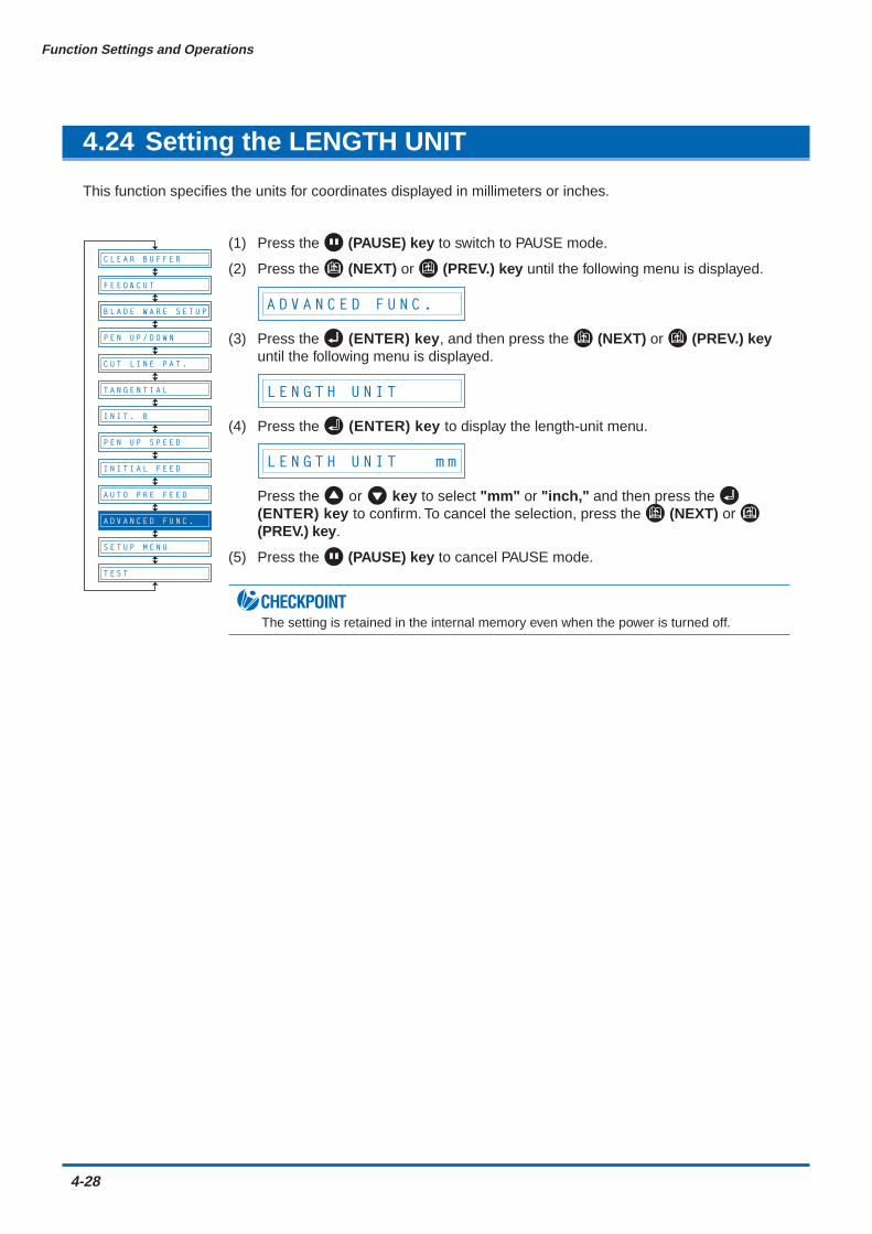
4-28
Function Settings and Operations
4.24 Setting the LENGTH UNIT
This function specifies the units for coordinates displayed in millimeters or inches.
(1) Press the (PAUSE) key to switch to PAUSE mode.
(2) Press the (NEXT) or (PREV.) key until the following menu is displayed.
A D V A N C E D F U N C .
(3) Press the (ENTER) key, and then press the (NEXT) or (PREV.) keyuntil the following menu is displayed.
L E N G T H U N I T
(4) Press the (ENTER) key to display the length-unit menu.
L E N G T H U N I T m m
Press the or key to select "mm" or "inch," and then press the (ENTER) key to confirm. To cancel the selection, press the (NEXT) or (PREV.) key.
(5) Press the (PAUSE) key to cancel PAUSE mode.
CHECKPOINTThe setting is retained in the internal memory even when the power is turned off.
B L A D E W A R E S E T U P
C U T L I N E P A T .
T A N G E N T I A L
I N I T . B
P E N U P S P E E D
I N I T I A L F E E D
A U T O P R E F E E D
S E T U P M E N U
T E S T
F E E D & C U T
P E N U P / D O W N
A D V A N C E D F U N C .
C L E A R B U F F E R
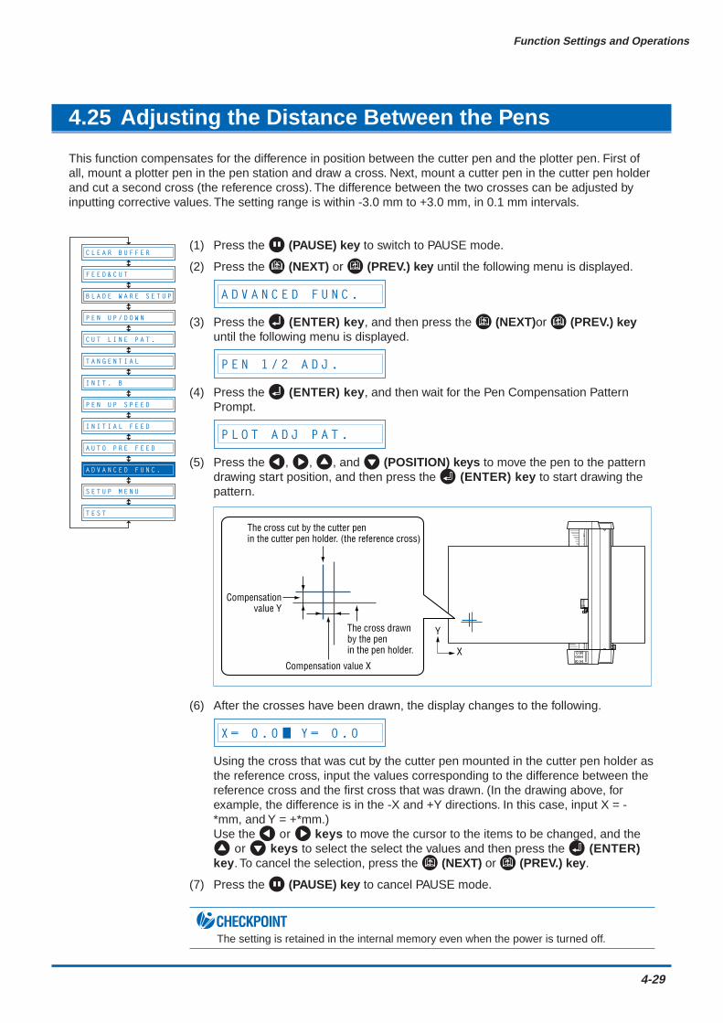
Function Settings and Operations
4-29
4.25 Adjusting the Distance Between the Pens
This function compensates for the difference in position between the cutter pen and the plotter pen. First ofall, mount a plotter pen in the pen station and draw a cross. Next, mount a cutter pen in the cutter pen holderand cut a second cross (the reference cross). The difference between the two crosses can be adjusted byinputting corrective values. The setting range is within -3.0 mm to +3.0 mm, in 0.1 mm intervals.
(1) Press the (PAUSE) key to switch to PAUSE mode.
(2) Press the (NEXT) or (PREV.) key until the following menu is displayed.
A D V A N C E D F U N C .
(3) Press the (ENTER) key, and then press the (NEXT)or (PREV.) keyuntil the following menu is displayed.
P E N 1 / 2 A D J .
(4) Press the (ENTER) key, and then wait for the Pen Compensation PatternPrompt.
P L O T A D J P A T .
(5) Press the , , , and (POSITION) keys to move the pen to the patterndrawing start position, and then press the (ENTER) key to start drawing thepattern.
Compensation value X
Compensationvalue Y
The cross drawnby the penin the pen holder.
The cross cut by the cutter penin the cutter pen holder. (the reference cross)
Y
X
(6) After the crosses have been drawn, the display changes to the following.
X = 0 . 0 Y = 0 . 0
Using the cross that was cut by the cutter pen mounted in the cutter pen holder asthe reference cross, input the values corresponding to the difference between thereference cross and the first cross that was drawn. (In the drawing above, forexample, the difference is in the -X and +Y directions. In this case, input X = -*mm, and Y = +*mm.)Use the or keys to move the cursor to the items to be changed, and the
or keys to select the select the values and then press the (ENTER)key. To cancel the selection, press the (NEXT) or (PREV.) key.
(7) Press the (PAUSE) key to cancel PAUSE mode.
CHECKPOINTThe setting is retained in the internal memory even when the power is turned off.
B L A D E W A R E S E T U P
C U T L I N E P A T .
T A N G E N T I A L
I N I T . B
P E N U P S P E E D
I N I T I A L F E E D
A U T O P R E F E E D
S E T U P M E N U
T E S T
F E E D & C U T
P E N U P / D O W N
A D V A N C E D F U N C .
C L E A R B U F F E R
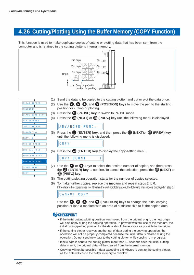
4-30
Function Settings and Operations
4.26 Cutting/Plotting Using the Buffer Memory (COPY Function)
This function is used to make duplicate copies of cutting or plotting data that has been sent from thecomputer and is retained in the cutting plotter's internal memory.
Y
X
Origin
Copy origin(Initial position for plotting copy)
1st copy
2nd copy
3rd copy
4th copy
5th copy
6th copy
(1) Send the data to be copied to the cutting plotter, and cut or plot the data once.
(2) Use the , , , and (POSITION) keys to move the pen to the startingposition for cutting or plotting.
(3) Press the (PAUSE) key to switch to PAUSE mode.
(4) Press the (NEXT) or (PREV.) key until the following menu is displayed.
A D V A N C E D F U N C .
(5) Press the (ENTER) key, and then press the (NEXT)or (PREV.) keyuntil the following menu is displayed.
C O P Y
(6) Press the (ENTER) key to display the copy-setting menu.
C O P Y C O U N T 1
(7) Use the or keys to select the desired number of copies, and then pressthe (ENTER) key to confirm. To cancel the selection, press the (NEXT) or
(PREV.) key.
(8) The cutting/plotting operation starts for the number of copies selected.
(9) To make further copies, replace the medium and repeat steps 2 to 6.If the data to be copied does not fit within the cutting/plotting area, the following message is displayed in step 5.
C A N N O T C O P Y
Use the , , , and (POSITION) keys to change the initial copyingposition or load a medium with an area of sufficient size to fit the copied data.
CHECKPOINT• If the initial cutting/plotting position was moved from the original origin, the new origin
will also apply during the copying operation. To prevent wasteful use of the medium, theinitial cutting/plotting position for the data should be as close as possible to the origin.
• If the cutting plotter receives another set of data during the copying operation, theoperation will not be properly completed because the initial data is cleared during theoperation. Do not send new data to the cutting plotter while copying is in progress.
• If new data is sent to the cutting plotter more than 10 seconds after the initial cuttingdata is sent, the original data will be cleared from the internal memory.
• Copying will not be possible if data exceeding 1.5 Mbytes is sent to the cutting plotter,as the data will cause the buffer memory to overflow.
B L A D E W A R E S E T U P
C U T L I N E P A T .
T A N G E N T I A L
I N I T . B
P E N U P S P E E D
I N I T I A L F E E D
A U T O P R E F E E D
S E T U P M E N U
T E S T
F E E D & C U T
P E N U P / D O W N
A D V A N C E D F U N C .
C L E A R B U F F E R
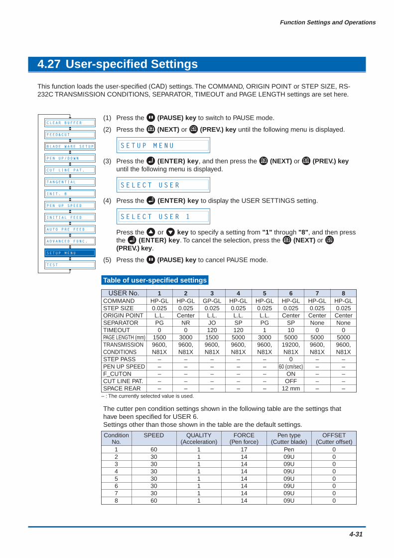
Function Settings and Operations
4-31
4.27 User-specified Settings
This function loads the user-specified (CAD) settings. The COMMAND, ORIGIN POINT or STEP SIZE, RS-232C TRANSMISSION CONDITIONS, SEPARATOR, TIMEOUT and PAGE LENGTH settings are set here.
(1) Press the (PAUSE) key to switch to PAUSE mode.
(2) Press the (NEXT) or (PREV.) key until the following menu is displayed.
S E T U P M E N U
(3) Press the (ENTER) key, and then press the (NEXT) or (PREV.) keyuntil the following menu is displayed.
S E L E C T U S E R
(4) Press the (ENTER) key to display the USER SETTINGS setting.
S E L E C T U S E R 1
Press the or key to specify a setting from "1" through "8", and then pressthe (ENTER) key. To cancel the selection, press the (NEXT) or (PREV.) key.
(5) Press the (PAUSE) key to cancel PAUSE mode.
Table of user-specified settings
The cutter pen condition settings shown in the following table are the settings thathave been specified for USER 6.Settings other than those shown in the table are the default settings.
B L A D E W A R E S E T U P
C U T L I N E P A T .
T A N G E N T I A L
I N I T . B
P E N U P S P E E D
I N I T I A L F E E D
T E S T
F E E D & C U T
P E N U P / D O W N
C L E A R B U F F E R
A U T O P R E F E E D
A D V A N C E D F U N C .
S E T U P M E N U
USER No. 1 2 3 4 5 6 7 8COMMAND HP-GL HP-GL GP-GL HP-GL HP-GL HP-GL HP-GL HP-GLSTEP SIZE 0.025 0.025 0.025 0.025 0.025 0.025 0.025 0.025ORIGIN POINT L.L. Center L.L. L.L. L.L. Center Center CenterSEPARATOR PG NR JO SP PG SP None NoneTIMEOUT 0 0 120 120 1 10 0 0PAGE LENGTH (mm) 1500 3000 1500 5000 3000 5000 5000 5000TRANSMISSION 9600, 9600, 9600, 9600, 9600, 19200, 9600, 9600,CONDITIONS N81X N81X N81X N81X N81X N81X N81X N81XSTEP PASS – – – – – 0 – –PEN UP SPEED – – – – – 60 (cm/sec) – –F_CUTON – – – – – ON – –CUT LINE PAT. – – – – – OFF – –SPACE REAR – – – – – 12 mm – –
– : The currently selected value is used.
Condition SPEED QUALITY FORCE Pen type OFFSETNo. (Acceleration) (Pen force) (Cutter blade) (Cutter offset)1 60 1 17 Pen 02 30 1 14 09U 03 30 1 14 09U 04 30 1 14 09U 05 30 1 14 09U 06 30 1 14 09U 07 30 1 14 09U 08 60 1 14 09U 0

4-32
Function Settings and Operations
4.28 Setting the Format of Data to be Received
Before data is sent from the computer, the format (command mode) of data sent by the application softwaremust be checked. The cutting plotter accepts two data formats (command modes): GP-GL (Graphtec) andHP-GL commands. Set the command mode to suit the application used.
Setting the Command Mode
(1) Press the (PAUSE) key to switch to PAUSE mode.
(2) Press the (NEXT) or (PREV.) key until the following menu is displayed.
S E T U P M E N U
(3) Press the (ENTER) key, and then press the (NEXT) or (PREV.) keyuntil the following menu is displayed.
C O M M A N D
(4) Press the (ENTER) key to display the command-setting menu.
C O M M A N D G P - G L
(5) Press the or key to select "GP-GL" or "HP-GL," and then press the (ENTER) key to confirm. To cancel the selection, press the (NEXT) or (PREV.) key.
(6) If "GP-GL" is selected, set the STEP SIZE. If "HP-GL" is selected, set theORIGIN POINT. If a command different from that set previously is selected, thePAUSE mode is automatically canceled after STEP SIZE (GP-GL) or ORIGINPOINT (HP-GL) is set.
Setting the STEP SIZE
If the GP-GL command mode is set, the minimum unit of distance that the pen cantravel can be changed to one of four settings: 0.01 mm, 0.025 mm, 0.05 mm, or 0.1mm. The default setting is 0.1 mm, so change this setting if your application specifies adifferent step size.
(1) Set the command setting to "GP-GL."
C O M M A N D G P - G L
(2) Press the (ENTER) key to display the step-size setting menu.
STEP SIZE 0.100mm
(3) Press the or key to select "0.100 mm," "0.050 mm," "0.025 mm," or"0.010 mm," and then press the (ENTER) key to confirm. To cancel theselection, press the (NEXT) or (PREV.) key.
(4) Press the (PAUSE) key to cancel PAUSE mode.
B L A D E W A R E S E T U P
C U T L I N E P A T .
T A N G E N T I A L
I N I T . B
P E N U P S P E E D
I N I T I A L F E E D
T E S T
F E E D & C U T
P E N U P / D O W N
C L E A R B U F F E R
A U T O P R E F E E D
A D V A N C E D F U N C .
S E T U P M E N U
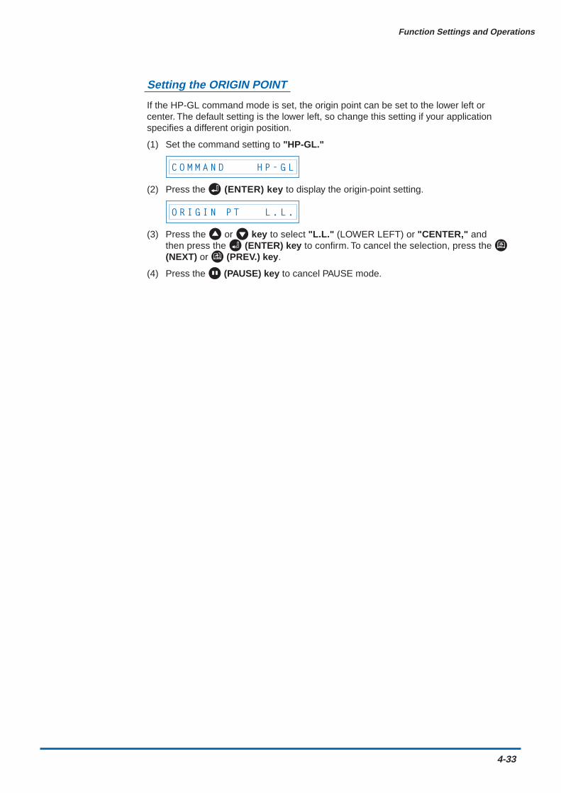
Function Settings and Operations
4-33
Setting the ORIGIN POINT
If the HP-GL command mode is set, the origin point can be set to the lower left orcenter. The default setting is the lower left, so change this setting if your applicationspecifies a different origin position.
(1) Set the command setting to "HP-GL."
C O M M A N D H P - G L
(2) Press the (ENTER) key to display the origin-point setting.
O R I G I N P T L . L .
(3) Press the or key to select "L.L." (LOWER LEFT) or "CENTER," andthen press the (ENTER) key to confirm. To cancel the selection, press the (NEXT) or (PREV.) key.
(4) Press the (PAUSE) key to cancel PAUSE mode.
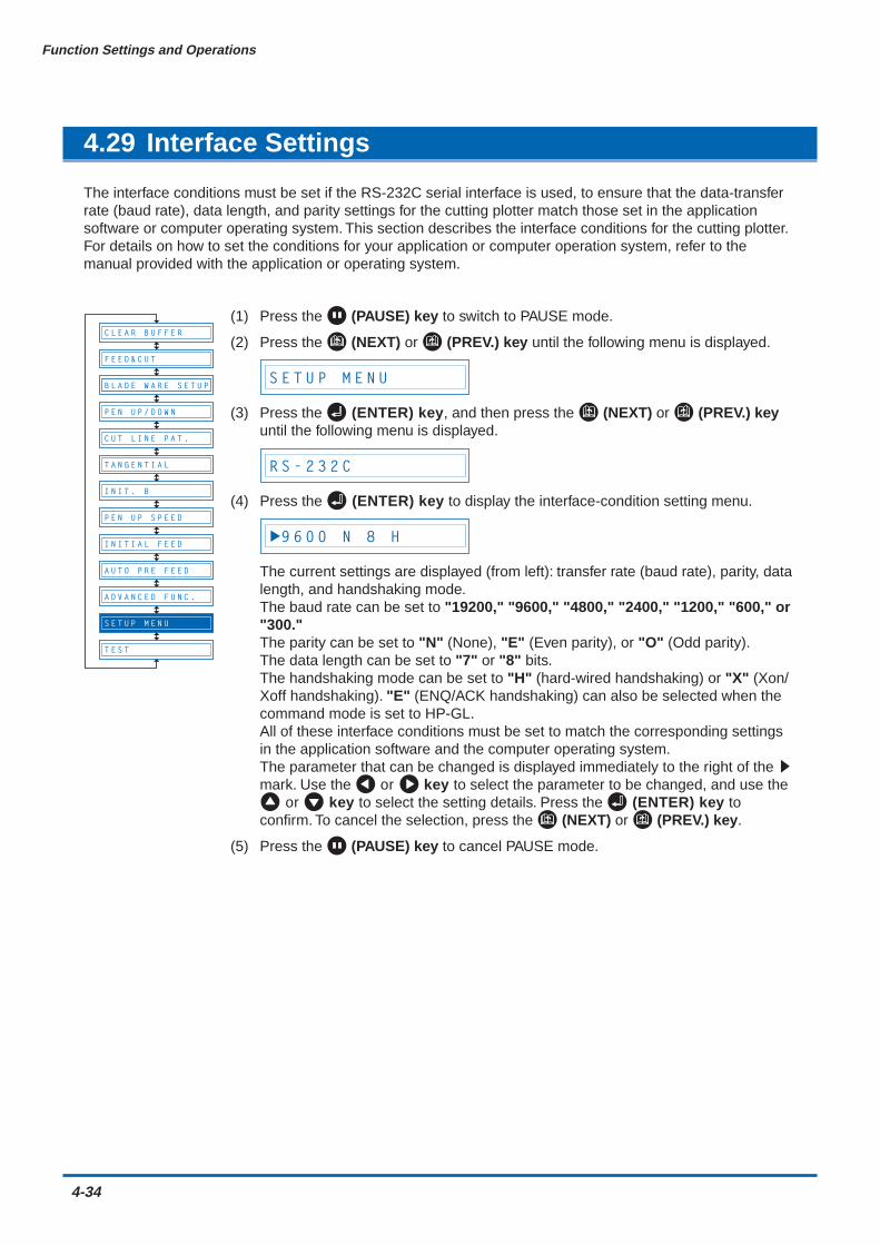
4-34
Function Settings and Operations
4.29 Interface Settings
The interface conditions must be set if the RS-232C serial interface is used, to ensure that the data-transferrate (baud rate), data length, and parity settings for the cutting plotter match those set in the applicationsoftware or computer operating system. This section describes the interface conditions for the cutting plotter.For details on how to set the conditions for your application or computer operation system, refer to themanual provided with the application or operating system.
(1) Press the (PAUSE) key to switch to PAUSE mode.
(2) Press the (NEXT) or (PREV.) key until the following menu is displayed.
S E T U P M E N U
(3) Press the (ENTER) key, and then press the (NEXT) or (PREV.) keyuntil the following menu is displayed.
R S - 2 3 2 C
(4) Press the (ENTER) key to display the interface-condition setting menu.
9 6 0 0 N 8 H
The current settings are displayed (from left): transfer rate (baud rate), parity, datalength, and handshaking mode.The baud rate can be set to "19200," "9600," "4800," "2400," "1200," "600," or"300."The parity can be set to "N" (None), "E" (Even parity), or "O" (Odd parity).The data length can be set to "7" or "8" bits.The handshaking mode can be set to "H" (hard-wired handshaking) or "X" (Xon/Xoff handshaking). "E" (ENQ/ACK handshaking) can also be selected when thecommand mode is set to HP-GL.All of these interface conditions must be set to match the corresponding settingsin the application software and the computer operating system.The parameter that can be changed is displayed immediately to the right of the smark. Use the or key to select the parameter to be changed, and use the
or key to select the setting details. Press the (ENTER) key toconfirm. To cancel the selection, press the (NEXT) or (PREV.) key.
(5) Press the (PAUSE) key to cancel PAUSE mode.
B L A D E W A R E S E T U P
C U T L I N E P A T .
T A N G E N T I A L
I N I T . B
P E N U P S P E E D
I N I T I A L F E E D
T E S T
F E E D & C U T
P E N U P / D O W N
C L E A R B U F F E R
A U T O P R E F E E D
A D V A N C E D F U N C .
S E T U P M E N U

Function Settings and Operations
4-35
4.30 Setting the PAGE LENGTH
This function sets the length of each page when long-axis cutting or plotting is performed using a rollmedium. This should be set for long-axis cutting or plotting exceeding 5 m in length. The default setting is"5000 mm."
(1) Press the (PAUSE) key to switch to PAUSE mode.
(2) Press the (NEXT) or (PREV.) key until the following menu is displayed.
S E T U P M E N U
(3) Press the (ENTER) key, and then press the (NEXT) or (PREV.) keyuntil the following menu is displayed.
P A G E L E N G T H
(4) Press the (ENTER) key to display the page-length menu.
L = 0 5 0 0 0 m m
Use the or key to move the cursor to the digit to be changed. Use the and keys to increase or decrease the setting, and then press the (ENTER) key to confirm. To cancel, press the (NEXT) or (PREV.) key.
(5) Press the (PAUSE) key to cancel PAUSE mode.
CHECKPOINT• This setting is retained in the memory even when the power is turned off.
• The cutting plotter's distance precision is guaranteed for page-feed lengths of up to 3meters. Long-axis cutting over 5 meters is possible for lengths of up to 50 meters in thefeeding direction.
• In the case of long-axis cutting, be particularly careful when loading the meduim. If themeduim is loaded at even a slight angle, it may come loose from the rollers that hold itin place.
CAUTION• Before using roll paper, perform the pre-feed (see "4.10 Specifying the INITIAL FEED
LENGTH" and "4.11 Setting AUTO PRE-FEED") and paper acclimation (see "4.33Setting the PAPER READY TIME" and "4.34 Setting the PAPER LOAD Function")operations. (Precision is not guaranteed unless these operations are performed.)
• Make sure that the operating environment is within the range given for the guaranteedprecision operating environment and, in particular, that changes in temperature andhumidity are minimized insofar as possible.
• When cutting or plotting a long-axis design, use the paper receptacle (media basket)with its opening widened.
B L A D E W A R E S E T U P
C U T L I N E P A T .
T A N G E N T I A L
I N I T . B
P E N U P S P E E D
I N I T I A L F E E D
T E S T
F E E D & C U T
P E N U P / D O W N
C L E A R B U F F E R
A U T O P R E F E E D
A D V A N C E D F U N C .
S E T U P M E N U
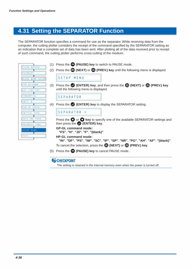
4-36
Function Settings and Operations
4.31 Setting the SEPARATOR Function
The SEPARATOR function specifies a command for use as the separator. While receiving data from thecomputer, the cutting plotter considers the receipt of the command specified by the SEPARATOR setting asan indication that a complete set of data has been sent. After plotting all of the data received prior to receiptof such command, the cutting plotter performs cross-cutting of the medium.
(1) Press the (PAUSE) key to switch to PAUSE mode.
(2) Press the (NEXT) or (PREV.) key until the following menu is displayed.
S E T U P M E N U
(3) Press the (ENTER) key, and then press the (NEXT) or (PREV.) keyuntil the following menu is displayed.
S E P A R A T O R
(4) Press the (ENTER) key to display the SEPARATOR setting.
S E P A R A T O R =
Press the or key to specify one of the available SEPARATOR settings andthen press the (ENTER) key.
GP-GL command mode:"FS", "H", "J0", "F", "(blank)"
HP-GL command mode:"IN", "DF", "PS", "IW", "SC", "IP", "SP", "NR", "PG", "AH", "AF", "(blank)"
To cancel the selection, press the (NEXT) or (PREV.) key.
(5) Press the (PAUSE) key to cancel PAUSE mode.
CHECKPOINTThe setting is retained in the internal memory even when the power is turned off.
B L A D E W A R E S E T U P
C U T L I N E P A T .
T A N G E N T I A L
I N I T . B
P E N U P S P E E D
I N I T I A L F E E D
T E S T
F E E D & C U T
P E N U P / D O W N
C L E A R B U F F E R
A U T O P R E F E E D
A D V A N C E D F U N C .
S E T U P M E N U
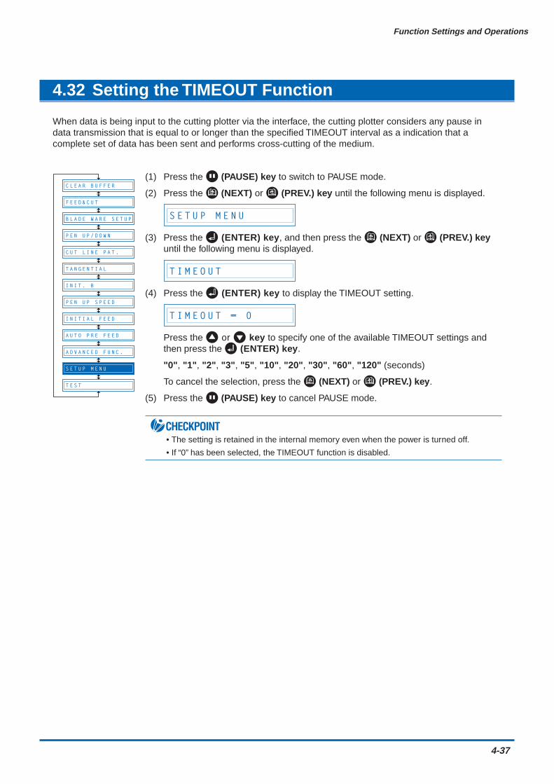
Function Settings and Operations
4-37
4.32 Setting the TIMEOUT Function
When data is being input to the cutting plotter via the interface, the cutting plotter considers any pause indata transmission that is equal to or longer than the specified TIMEOUT interval as a indication that acomplete set of data has been sent and performs cross-cutting of the medium.
(1) Press the (PAUSE) key to switch to PAUSE mode.
(2) Press the (NEXT) or (PREV.) key until the following menu is displayed.
S E T U P M E N U
(3) Press the (ENTER) key, and then press the (NEXT) or (PREV.) keyuntil the following menu is displayed.
T I M E O U T
(4) Press the (ENTER) key to display the TIMEOUT setting.
T I M E O U T = 0
Press the or key to specify one of the available TIMEOUT settings andthen press the (ENTER) key.
"0", "1", "2", "3", "5", "10", "20", "30", "60", "120" (seconds)
To cancel the selection, press the (NEXT) or (PREV.) key.
(5) Press the (PAUSE) key to cancel PAUSE mode.
CHECKPOINT• The setting is retained in the internal memory even when the power is turned off.
• If “0” has been selected, the TIMEOUT function is disabled.
B L A D E W A R E S E T U P
C U T L I N E P A T .
T A N G E N T I A L
I N I T . B
P E N U P S P E E D
I N I T I A L F E E D
T E S T
F E E D & C U T
P E N U P / D O W N
C L E A R B U F F E R
A U T O P R E F E E D
A D V A N C E D F U N C .
S E T U P M E N U
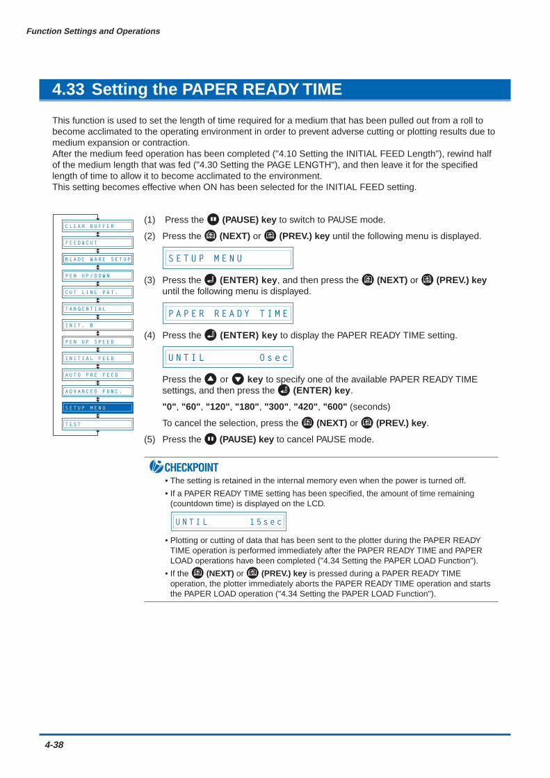
4-38
Function Settings and Operations
4.33 Setting the PAPER READY TIME
This function is used to set the length of time required for a medium that has been pulled out from a roll tobecome acclimated to the operating environment in order to prevent adverse cutting or plotting results due tomedium expansion or contraction.After the medium feed operation has been completed ("4.10 Setting the INITIAL FEED Length"), rewind halfof the medium length that was fed ("4.30 Setting the PAGE LENGTH"), and then leave it for the specifiedlength of time to allow it to become acclimated to the environment.This setting becomes effective when ON has been selected for the INITIAL FEED setting.
(1) Press the (PAUSE) key to switch to PAUSE mode.
(2) Press the (NEXT) or (PREV.) key until the following menu is displayed.
S E T U P M E N U
(3) Press the (ENTER) key, and then press the (NEXT) or (PREV.) keyuntil the following menu is displayed.
P A P E R R E A D Y T I M E
(4) Press the (ENTER) key to display the PAPER READY TIME setting.
U N T I L 0 s e c
Press the or key to specify one of the available PAPER READY TIMEsettings, and then press the (ENTER) key.
"0", "60", "120", "180", "300", "420", "600" (seconds)
To cancel the selection, press the (NEXT) or (PREV.) key.
(5) Press the (PAUSE) key to cancel PAUSE mode.
CHECKPOINT• The setting is retained in the internal memory even when the power is turned off.
• If a PAPER READY TIME setting has been specified, the amount of time remaining(countdown time) is displayed on the LCD.
U N T I L 1 5 s e c
• Plotting or cutting of data that has been sent to the plotter during the PAPER READYTIME operation is performed immediately after the PAPER READY TIME and PAPERLOAD operations have been completed ("4.34 Setting the PAPER LOAD Function").
• If the (NEXT) or (PREV.) key is pressed during a PAPER READY TIMEoperation, the plotter immediately aborts the PAPER READY TIME operation and startsthe PAPER LOAD operation ("4.34 Setting the PAPER LOAD Function").
B L A D E W A R E S E T U P
C U T L I N E P A T .
T A N G E N T I A L
I N I T . B
P E N U P S P E E D
I N I T I A L F E E D
T E S T
F E E D & C U T
P E N U P / D O W N
C L E A R B U F F E R
A U T O P R E F E E D
A D V A N C E D F U N C .
S E T U P M E N U
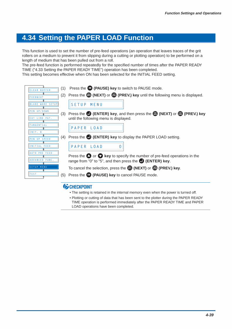
Function Settings and Operations
4-39
4.34 Setting the PAPER LOAD Function
This function is used to set the number of pre-feed operations (an operation that leaves traces of the gritrollers on a medium to prevent it from slipping during a cutting or plotting operation) to be performed on alength of medium that has been pulled out from a roll.The pre-feed function is performed repeatedly for the specified number of times after the PAPER READYTIME ("4.33 Setting the PAPER READY TIME") operation has been completed.This setting becomes effective when ON has been selected for the INITIAL FEED setting.
(1) Press the (PAUSE) key to switch to PAUSE mode.
(2) Press the (NEXT) or (PREV.) key until the following menu is displayed.
S E T U P M E N U
(3) Press the (ENTER) key, and then press the (NEXT) or (PREV.) keyuntil the following menu is displayed.
P A P E R L O A D
(4) Press the (ENTER) key to display the PAPER LOAD setting.
P A P E R L O A D 0
Press the or key to specify the number of pre-feed operations in therange from "0" to "5", and then press the (ENTER) key.
To cancel the selection, press the (NEXT) or (PREV.) key.
(5) Press the (PAUSE) key to cancel PAUSE mode.
CHECKPOINT• The setting is retained in the internal memory even when the power is turned off.
• Plotting or cutting of data that has been sent to the plotter during the PAPER READYTIME operation is performed immediately after the PAPER READY TIME and PAPERLOAD operations have been completed.
B L A D E W A R E S E T U P
C U T L I N E P A T .
T A N G E N T I A L
I N I T . B
P E N U P S P E E D
I N I T I A L F E E D
T E S T
F E E D & C U T
P E N U P / D O W N
C L E A R B U F F E R
A U T O P R E F E E D
A D V A N C E D F U N C .
S E T U P M E N U
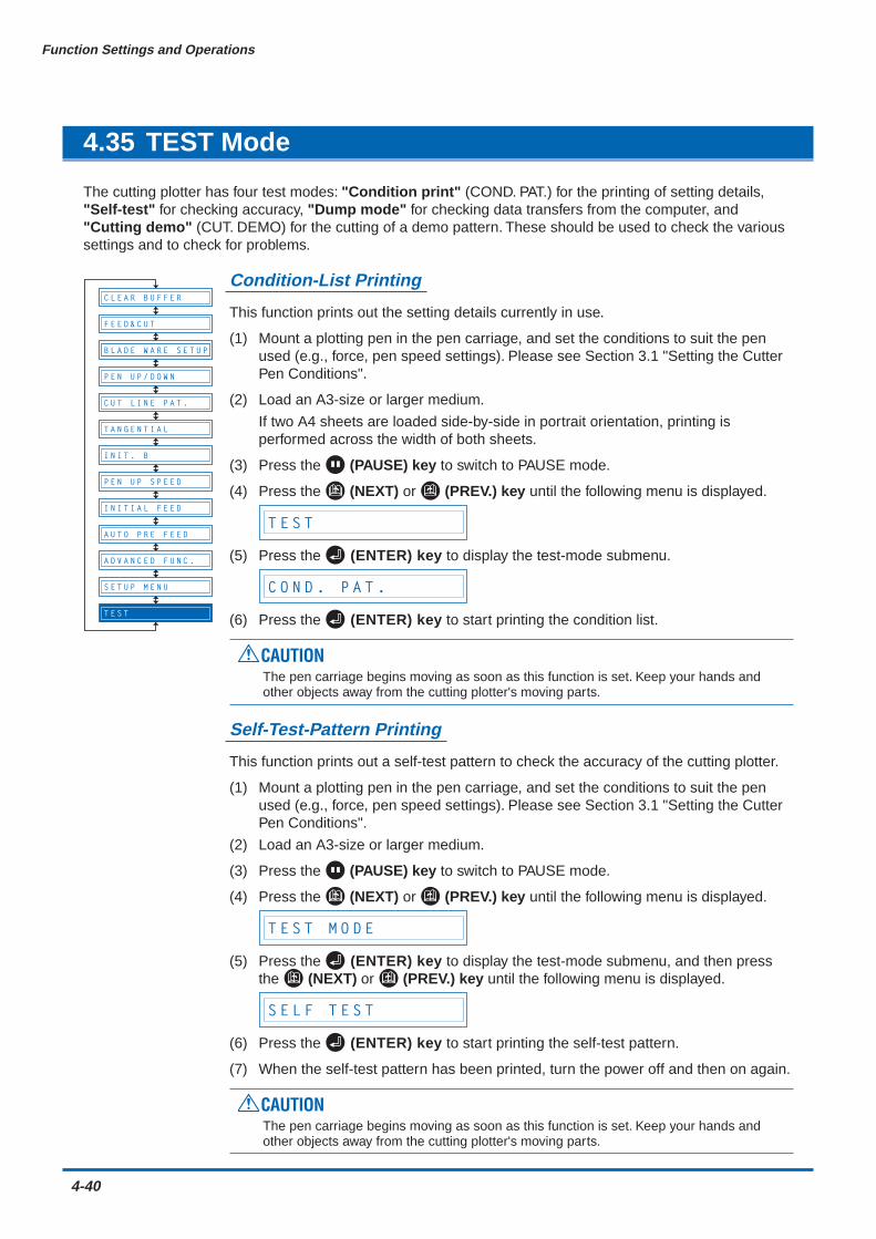
4-40
Function Settings and Operations
4.35 TEST Mode
The cutting plotter has four test modes: "Condition print" (COND. PAT.) for the printing of setting details,"Self-test" for checking accuracy, "Dump mode" for checking data transfers from the computer, and"Cutting demo" (CUT. DEMO) for the cutting of a demo pattern. These should be used to check the varioussettings and to check for problems.
Condition-List Printing
This function prints out the setting details currently in use.
(1) Mount a plotting pen in the pen carriage, and set the conditions to suit the penused (e.g., force, pen speed settings). Please see Section 3.1 "Setting the CutterPen Conditions".
(2) Load an A3-size or larger medium.
If two A4 sheets are loaded side-by-side in portrait orientation, printing isperformed across the width of both sheets.
(3) Press the (PAUSE) key to switch to PAUSE mode.
(4) Press the (NEXT) or (PREV.) key until the following menu is displayed.
T E S T
(5) Press the (ENTER) key to display the test-mode submenu.
C O N D . P A T .
(6) Press the (ENTER) key to start printing the condition list.
CAUTIONThe pen carriage begins moving as soon as this function is set. Keep your hands andother objects away from the cutting plotter's moving parts.
Self-Test-Pattern Printing
This function prints out a self-test pattern to check the accuracy of the cutting plotter.
(1) Mount a plotting pen in the pen carriage, and set the conditions to suit the penused (e.g., force, pen speed settings). Please see Section 3.1 "Setting the CutterPen Conditions".
(2) Load an A3-size or larger medium.
(3) Press the (PAUSE) key to switch to PAUSE mode.
(4) Press the (NEXT) or (PREV.) key until the following menu is displayed.
T E S T M O D E
(5) Press the (ENTER) key to display the test-mode submenu, and then pressthe (NEXT) or (PREV.) key until the following menu is displayed.
S E L F T E S T
(6) Press the (ENTER) key to start printing the self-test pattern.
(7) When the self-test pattern has been printed, turn the power off and then on again.
CAUTIONThe pen carriage begins moving as soon as this function is set. Keep your hands andother objects away from the cutting plotter's moving parts.
B L A D E W A R E S E T U P
C U T L I N E P A T .
T A N G E N T I A L
I N I T . B
P E N U P S P E E D
I N I T I A L F E E D
A U T O P R E F E E D
S E T U P M E N U
F E E D & C U T
P E N U P / D O W N
C L E A R B U F F E R
A D V A N C E D F U N C .
T E S T
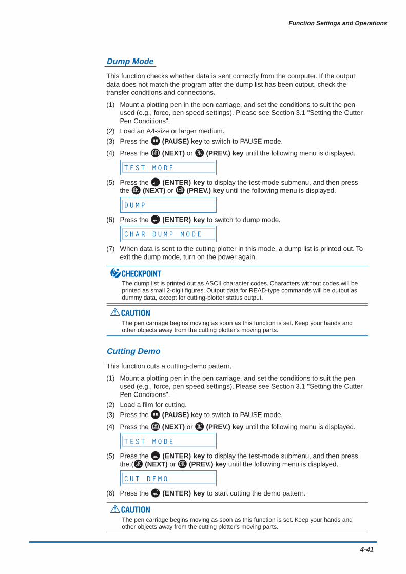
Function Settings and Operations
4-41
Dump Mode
This function checks whether data is sent correctly from the computer. If the outputdata does not match the program after the dump list has been output, check thetransfer conditions and connections.
(1) Mount a plotting pen in the pen carriage, and set the conditions to suit the penused (e.g., force, pen speed settings). Please see Section 3.1 "Setting the CutterPen Conditions".
(2) Load an A4-size or larger medium.
(3) Press the (PAUSE) key to switch to PAUSE mode.
(4) Press the (NEXT) or (PREV.) key until the following menu is displayed.
T E S T M O D E
(5) Press the (ENTER) key to display the test-mode submenu, and then pressthe (NEXT) or (PREV.) key until the following menu is displayed.
D U M P
(6) Press the (ENTER) key to switch to dump mode.
C H A R D U M P M O D E
(7) When data is sent to the cutting plotter in this mode, a dump list is printed out. Toexit the dump mode, turn on the power again.
CHECKPOINTThe dump list is printed out as ASCII character codes. Characters without codes will beprinted as small 2-digit figures. Output data for READ-type commands will be output asdummy data, except for cutting-plotter status output.
CAUTIONThe pen carriage begins moving as soon as this function is set. Keep your hands andother objects away from the cutting plotter's moving parts.
Cutting Demo
This function cuts a cutting-demo pattern.
(1) Mount a plotting pen in the pen carriage, and set the conditions to suit the penused (e.g., force, pen speed settings). Please see Section 3.1 "Setting the CutterPen Conditions".
(2) Load a film for cutting.
(3) Press the (PAUSE) key to switch to PAUSE mode.
(4) Press the (NEXT) or (PREV.) key until the following menu is displayed.
T E S T M O D E
(5) Press the (ENTER) key to display the test-mode submenu, and then pressthe ( (NEXT) or (PREV.) key until the following menu is displayed.
C U T D E M O
(6) Press the (ENTER) key to start cutting the demo pattern.
CAUTIONThe pen carriage begins moving as soon as this function is set. Keep your hands andother objects away from the cutting plotter's moving parts.
CHAPTER 5Setting and Using the Special Functions
5.1 Description of Special Functions A5.2 Setting Special Functions A5.3 Description of Special Functions B5.4 Setting Special Functions B
5-2
Setting and Using the Special Functions
5.1 Description of Special Functions A
The cutting plotter is provided with the special functions described below. These functions are specified onlyin special situations, and are not normally used.
Enabling/Disabling the ":" and ";" Commands (when the COMMAND setting is GP-GL)This function enables or disables the ":" and ";" commands when the COMMAND setting is GP-GL.If the first part of the data is lost, these commands may be having an adverse effect. In this case,set this function to DISABLED(the default setting is ENABLED).
Moving the Pen While Raised or Lowered in Response to the "W" Command (when theCOMMAND setting is GP-GL)This function selects whether, upon receipt of the "W" command for the drawing of arcs, the cuttingplotter moves the pen to the specified starting position, raised or in the pen status (raised orlowered) that was in effect immediately prior to receipt of the "W" command.When PEN DOWN is selected, the pen is moved to the starting position for the drawing of arcs inthe pen status (raised or lowered) that was in effect immediately prior to receipt of the "W"command.When PEN UP is selected, the pen is moved to the starting position for the drawing of arcs in theraised status. This setting is only effective if a cutter blade has been selected in the cutter-pensettings.(The default setting is PEN UP.)
Model ID Response (when the COMMAND setting is HP-GL)This function sets the response to the "OI" command when the COMMAND setting is HP-GL.When 7550 is set, the "OI" command response is 7550.When 7586 is set, the "OI" command response is 7586.(The default setting is 7586.)
SETTING PRIORITYThis function sets whether the cutting plotter places priority on the cutting conditions specifiedthrough command input from the computer or through manual settings (on the cutting-plottercontrol panel).When MANUAL is selected, cutting is performed using the cutting conditions set at the controlpanel, and cutting conditions sent from the computer are ignored.When COMD is selected, cutting is performed using the cutting conditions specified in a receivedcutting-condition command. If no commands are received, cutting is performed using the cuttingconditions set at the control panel.(The default setting is COMD.)
Enabling/Disabling PEN UP MOVEThis function sets whether the pen will travel to each point specified or only from the initiallyspecified point to the last specified point when consecutive commands are received specifying penmovement while it is raised.When ENABLED is selected, the pen travels consecutively to each coordinate specified by the datareceived.When DISABLED is selected, the pen travels directly from the initially specified point to the lastspecified point.(The default setting is DISABLED.)
Setting and Using the Special Functions
5-3
Enabling/Disabling the Media SensorsThis function sets the media sensors that detect the size of the medium in the feed direction.When ENABLED is selected, the feed-direction media sensors are enabled.When DISABLED is selected, the feed-direction media sensors are disabled.(The default setting is ENABLED.)
Enabling/Disabling the Home SensorsThis function sets the home sensors that detect the width of the medium.When ENABLED is selected, the home sensors are enabled.When DISABLED is selected, the home sensors are disabled.(The default setting is ENABLED.)
Circle-Command Resolution Setting (when the COMMAND setting is HP-GL)This function sets whether the resolution is automatically set or fixed at a constant 5 degrees whena cutting-plotter circle command is output while the COMMAND setting is HP-GL.(The default setting is DEFAULT.)
Enabling/Disabling Blade Wear DetectionWhen ENABLED is selected, the blade wear-detection setting is enabled and the blade wear-detection setting menu is displayed in the PAUSE menu.When DISABLED is selected, the blade wear-detection setting is disabled, and the blade wear-detection setting menu is removed from the PAUSE menu and is not displayed. For details on weardetection, refer to see "4.4 Blade Wear Detection."(The default setting is DISABLED.)
Setting the Cross-Cut ForceThe cross-cut force can be set in the range "1" to "31".(The default value is 20)
PAUSE Key SettingSelects the screen to be displayed when you press the (PAUSE) key while cutting or plotting.If you serect "HOLD" the cutting plotter stops cutting or plotting and displays a jobselect screenprompting you to choose to continue or stop cutting/plotting.If you serect "MENU" the cutting plotter stops cutting or plotting and displays a pause menu screen.(The default setting is MENU)
CHECKPOINTIf the media or home sensors have been disabled (set to OFF), be sure to specify the cutting/plottingarea (see "4.14 Setting the Cutting/Plotting Area"). If the cutting/plotting area is not specified, thecutting mat may be damaged.

5-4
Setting and Using the Special Functions
5.2 Setting Special Functions A
(1) Turn on the cutting plotter while holding down the key. The menus for setting the specialfunctions are displayed.
“ : ” , “ : ” E N A B L E D
“ W ” P E N U P
P R I O R I T Y C O M D
U P M O D E D I S A B L E D
M E D I A E N A B L E D
H O M E E N A B L E D
B . W . S . D I S A B L E D
C R O S S C U T F O R C E 2 0
P A U S E K E Y M E N U
M O D E L 7 5 8 6
P R I O R I T Y C O M D
U P M O D E D I S A B L E D
M E D I A E N A B L E D
H O M E E N A B L E D
C I R C L E D E F A U L T
B . W . S . D I S A B L E D
C R O S S C U T F O R C E 2 0
P A U S E K E Y M E N U
In GP-GL command mode In HP-GL command mode
(2) Scroll up or down to select the required menu using the (NEXT) or (PREV.) key.
(3) Select the setting details using the or key, and press the (ENTER) key to registerthe setting. To cancel the selection, press the (NEXT) or (PREV.) key. The next menuis displayed.
(4) Once all the settings have been made, turn off the cutting plotter.
Setting and Using the Special Functions
5-5
5.3 Description of Special Functions B
These functions are specified only in the special situations described below, and are not normally used.
Display Language Setting (MENU LANGUAGE SELECTION)
This function sets the language used on the display. One of six languages can be selected: English,French, German, Italian, Spanish, or Japanese.
5.4 Setting Special Functions B
(1) Turn the cutting plotter on while holding down the (ENTER) and (ORIGIN) keyssimultaneously. The special functions B setting menu is displayed.
D I S P L A Y E N G L I S H
(2) Use the or key to select the desired display language, and then press the (ENTER)key to confirm. To cancel the selection, press the (NEXT) or (PREV.) key.
(3) Once all the settings have been made, turn off the cutting plotter.
CHAPTER 6Troubleshooting
6.1 The Cutting Plotter Does Not Operate When Turned On6.2 The Cutting Plotter Does Not Operate Correctly6.3 The Cutting Results Are Unsatisfactory6.4 An Error Message Was Displayed
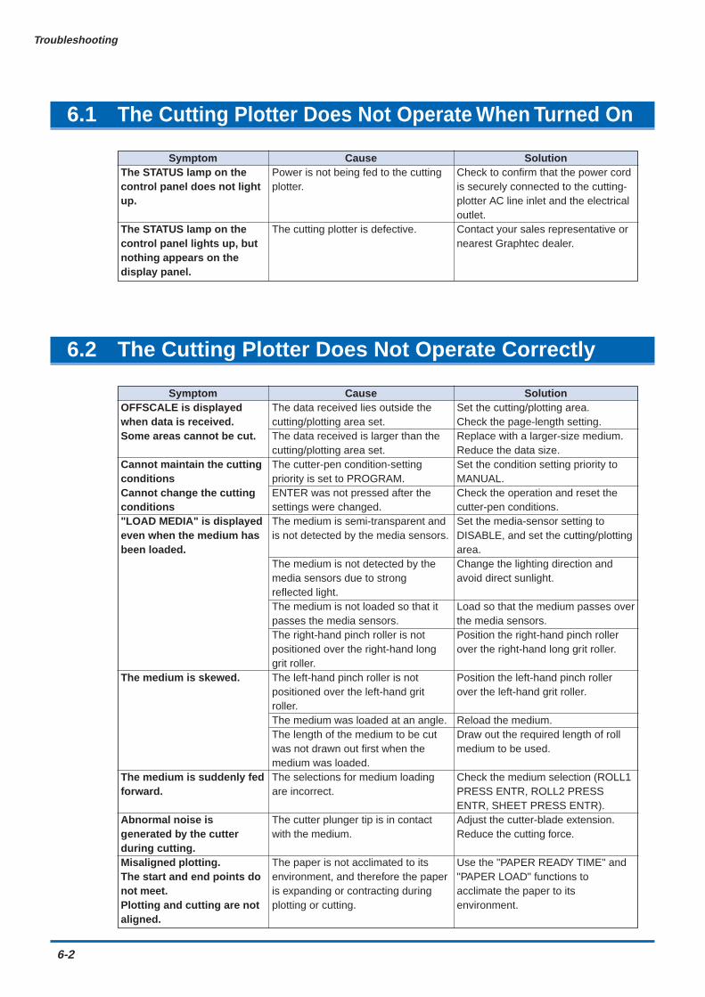
6-2
Troubleshooting
6.1 The Cutting Plotter Does Not Operate When Turned On
SymptomThe STATUS lamp on thecontrol panel does not lightup.
The STATUS lamp on thecontrol panel lights up, butnothing appears on thedisplay panel.
CausePower is not being fed to the cuttingplotter.
The cutting plotter is defective.
SolutionCheck to confirm that the power cordis securely connected to the cutting-plotter AC line inlet and the electricaloutlet.Contact your sales representative ornearest Graphtec dealer.
6.2 The Cutting Plotter Does Not Operate Correctly
SymptomOFFSCALE is displayedwhen data is received.Some areas cannot be cut.
Cannot maintain the cuttingconditionsCannot change the cuttingconditions"LOAD MEDIA" is displayedeven when the medium hasbeen loaded.
The medium is skewed.
The medium is suddenly fedforward.
Abnormal noise isgenerated by the cutterduring cutting.Misaligned plotting.The start and end points donot meet.Plotting and cutting are notaligned.
CauseThe data received lies outside thecutting/plotting area set.The data received is larger than thecutting/plotting area set.The cutter-pen condition-settingpriority is set to PROGRAM.ENTER was not pressed after thesettings were changed.The medium is semi-transparent andis not detected by the media sensors.
The medium is not detected by themedia sensors due to strongreflected light.The medium is not loaded so that itpasses the media sensors.The right-hand pinch roller is notpositioned over the right-hand longgrit roller.The left-hand pinch roller is notpositioned over the left-hand gritroller.The medium was loaded at an angle.The length of the medium to be cutwas not drawn out first when themedium was loaded.The selections for medium loadingare incorrect.
The cutter plunger tip is in contactwith the medium.
The paper is not acclimated to itsenvironment, and therefore the paperis expanding or contracting duringplotting or cutting.
SolutionSet the cutting/plotting area.Check the page-length setting.Replace with a larger-size medium.Reduce the data size.Set the condition setting priority toMANUAL.Check the operation and reset thecutter-pen conditions.Set the media-sensor setting toDISABLE, and set the cutting/plottingarea.Change the lighting direction andavoid direct sunlight.
Load so that the medium passes overthe media sensors.Position the right-hand pinch rollerover the right-hand long grit roller.
Position the left-hand pinch rollerover the left-hand grit roller.
Reload the medium.Draw out the required length of rollmedium to be used.
Check the medium selection (ROLL1PRESS ENTR, ROLL2 PRESSENTR, SHEET PRESS ENTR).Adjust the cutter-blade extension.Reduce the cutting force.
Use the "PAPER READY TIME" and"PAPER LOAD" functions toacclimate the paper to itsenvironment.
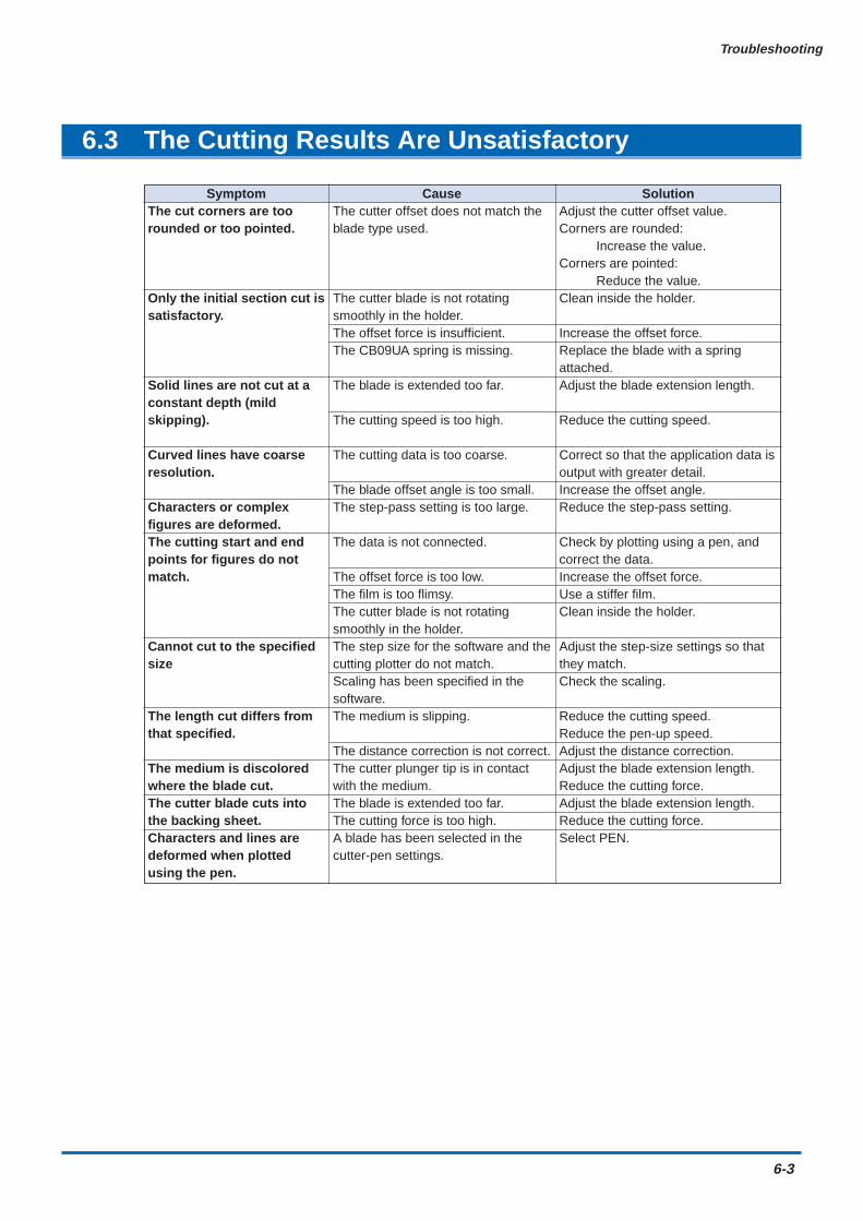
Troubleshooting
6-3
6.3 The Cutting Results Are Unsatisfactory
SymptomThe cut corners are toorounded or too pointed.
Only the initial section cut issatisfactory.
Solid lines are not cut at aconstant depth (mildskipping).
Curved lines have coarseresolution.
Characters or complexfigures are deformed.The cutting start and endpoints for figures do notmatch.
Cannot cut to the specifiedsize
The length cut differs fromthat specified.
The medium is discoloredwhere the blade cut.The cutter blade cuts intothe backing sheet.Characters and lines aredeformed when plottedusing the pen.
CauseThe cutter offset does not match theblade type used.
The cutter blade is not rotatingsmoothly in the holder.The offset force is insufficient.The CB09UA spring is missing.
The blade is extended too far.
The cutting speed is too high.
The cutting data is too coarse.
The blade offset angle is too small.The step-pass setting is too large.
The data is not connected.
The offset force is too low.The film is too flimsy.The cutter blade is not rotatingsmoothly in the holder.The step size for the software and thecutting plotter do not match.Scaling has been specified in thesoftware.The medium is slipping.
The distance correction is not correct.The cutter plunger tip is in contactwith the medium.The blade is extended too far.The cutting force is too high.A blade has been selected in thecutter-pen settings.
SolutionAdjust the cutter offset value.Corners are rounded:
Increase the value.Corners are pointed:
Reduce the value.Clean inside the holder.
Increase the offset force.Replace the blade with a springattached.Adjust the blade extension length.
Reduce the cutting speed.
Correct so that the application data isoutput with greater detail.Increase the offset angle.Reduce the step-pass setting.
Check by plotting using a pen, andcorrect the data.Increase the offset force.Use a stiffer film.Clean inside the holder.
Adjust the step-size settings so thatthey match.Check the scaling.
Reduce the cutting speed.Reduce the pen-up speed.Adjust the distance correction.Adjust the blade extension length.Reduce the cutting force.Adjust the blade extension length.Reduce the cutting force.Select PEN.

6-4
Troubleshooting
6.4 An Error Message Was Displayed
If any of the following command error messages appear, they are nearly always caused by one ofthe following two reasons:
• The software or host-computer settings have been changed.
• The cutting-plotter interface settings have been changed.
Solutions• Configure the settings in the software menu so that the menu can control the cutting plotter.
• Set the host-computer interface conditions correctly.
• Set the cutting-plotter interface conditions correctly.
SymptomCURRENT LIMIT orPOSITION ERROR isdisplayed.The POWER lamp flickers.
SPEED ERROR isdisplayed.The POWER lamp flickers.
CauseThe cutting conditions are notsuitable for the medium being cut.Excessive load is causing the currentto the motor to exceed the ratedvalue.The pen carriage movement is beingobstructed.The pen carriage was subjected toexternal pressure during cutting.Scraps of the medium in the movingparts are impeding operation.The stock shaft stopper is set to theLOCK position.If this problem occurs frequently, contact your sales representative ornearest Graphtec dealer.The pen carriage was subjected toexternal pressure after the powerwas turned on.The internal speed control is faulty.If this problem occurs frequently, contact your sales representative ornearest Graphtec dealer.
SolutionReduce the cutting speed.Reduce the cutting force.Remove the obstruction and turn thecutting plotter back on.
Set the stock shaft stopper to theFREE position.
Turn the cutting plotter off and thenback on again.
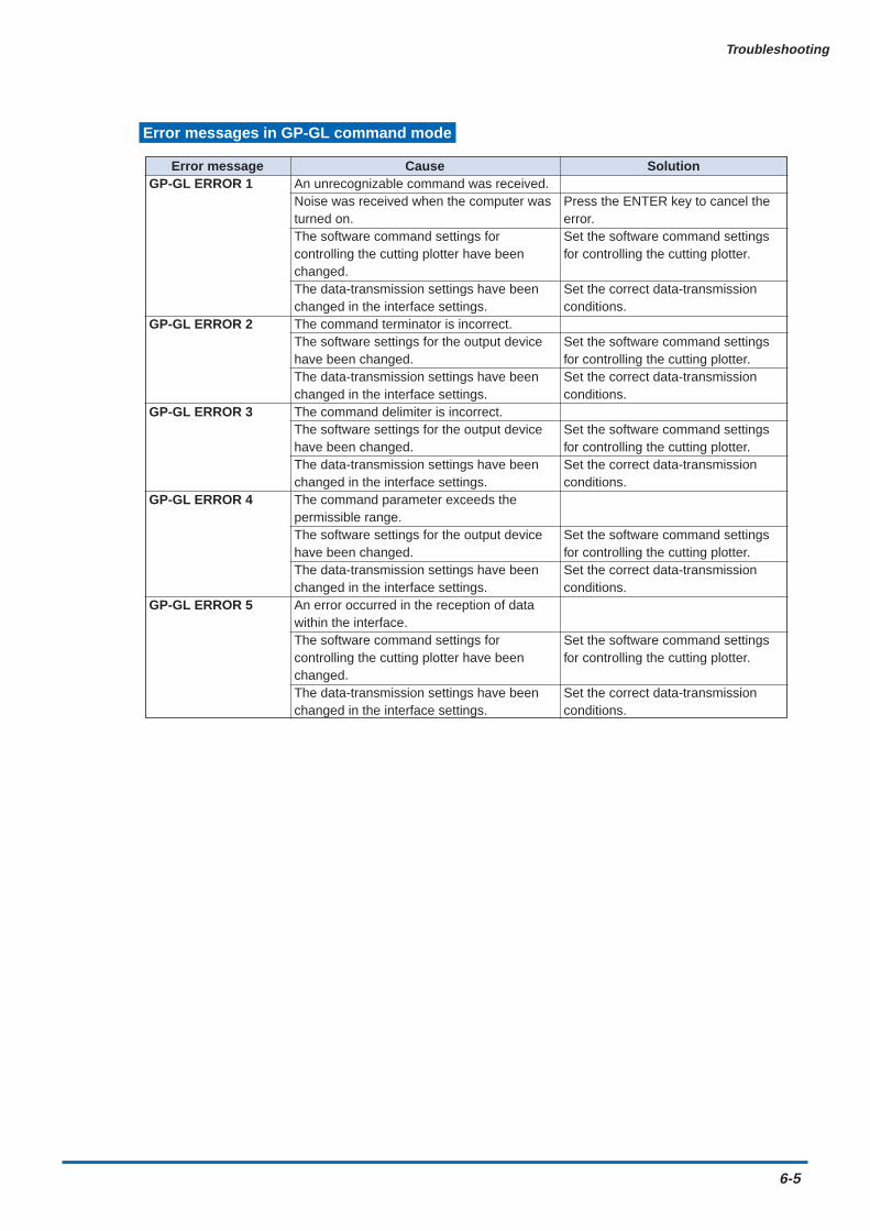
Troubleshooting
6-5
Error messages in GP-GL command mode
Error messageGP-GL ERROR 1
GP-GL ERROR 2
GP-GL ERROR 3
GP-GL ERROR 4
GP-GL ERROR 5
CauseAn unrecognizable command was received.Noise was received when the computer wasturned on.The software command settings forcontrolling the cutting plotter have beenchanged.The data-transmission settings have beenchanged in the interface settings.The command terminator is incorrect.The software settings for the output devicehave been changed.The data-transmission settings have beenchanged in the interface settings.The command delimiter is incorrect.The software settings for the output devicehave been changed.The data-transmission settings have beenchanged in the interface settings.The command parameter exceeds thepermissible range.The software settings for the output devicehave been changed.The data-transmission settings have beenchanged in the interface settings.An error occurred in the reception of datawithin the interface.The software command settings forcontrolling the cutting plotter have beenchanged.The data-transmission settings have beenchanged in the interface settings.
Solution
Press the ENTER key to cancel theerror.Set the software command settingsfor controlling the cutting plotter.
Set the correct data-transmissionconditions.
Set the software command settingsfor controlling the cutting plotter.Set the correct data-transmissionconditions.
Set the software command settingsfor controlling the cutting plotter.Set the correct data-transmissionconditions.
Set the software command settingsfor controlling the cutting plotter.Set the correct data-transmissionconditions.
Set the software command settingsfor controlling the cutting plotter.
Set the correct data-transmissionconditions.
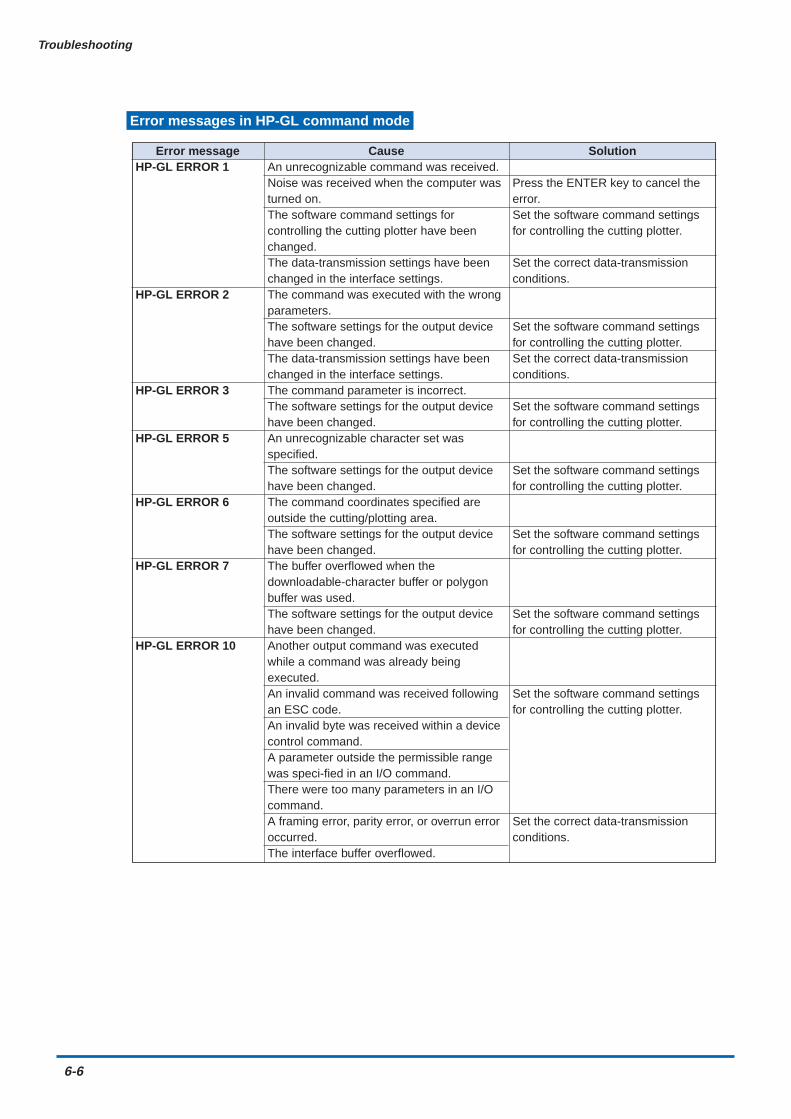
6-6
Troubleshooting
Error messages in HP-GL command mode
Error messageHP-GL ERROR 1
HP-GL ERROR 2
HP-GL ERROR 3
HP-GL ERROR 5
HP-GL ERROR 6
HP-GL ERROR 7
HP-GL ERROR 10
CauseAn unrecognizable command was received.Noise was received when the computer wasturned on.The software command settings forcontrolling the cutting plotter have beenchanged.The data-transmission settings have beenchanged in the interface settings.The command was executed with the wrongparameters.The software settings for the output devicehave been changed.The data-transmission settings have beenchanged in the interface settings.The command parameter is incorrect.The software settings for the output devicehave been changed.An unrecognizable character set wasspecified.The software settings for the output devicehave been changed.The command coordinates specified areoutside the cutting/plotting area.The software settings for the output devicehave been changed.The buffer overflowed when thedownloadable-character buffer or polygonbuffer was used.The software settings for the output devicehave been changed.Another output command was executedwhile a command was already beingexecuted.An invalid command was received followingan ESC code.An invalid byte was received within a devicecontrol command.A parameter outside the permissible rangewas speci-fied in an I/O command.There were too many parameters in an I/Ocommand.A framing error, parity error, or overrun erroroccurred.The interface buffer overflowed.
Solution
Press the ENTER key to cancel theerror.Set the software command settingsfor controlling the cutting plotter.
Set the correct data-transmissionconditions.
Set the software command settingsfor controlling the cutting plotter.Set the correct data-transmissionconditions.
Set the software command settingsfor controlling the cutting plotter.
Set the software command settingsfor controlling the cutting plotter.
Set the software command settingsfor controlling the cutting plotter.
Set the software command settingsfor controlling the cutting plotter.
Set the software command settingsfor controlling the cutting plotter.
Set the correct data-transmissionconditions.
Appendix
Appendix A Main SpecificationsAppendix B Options and SuppliesAppendix C External DimensionsAppendix D Menu Tree
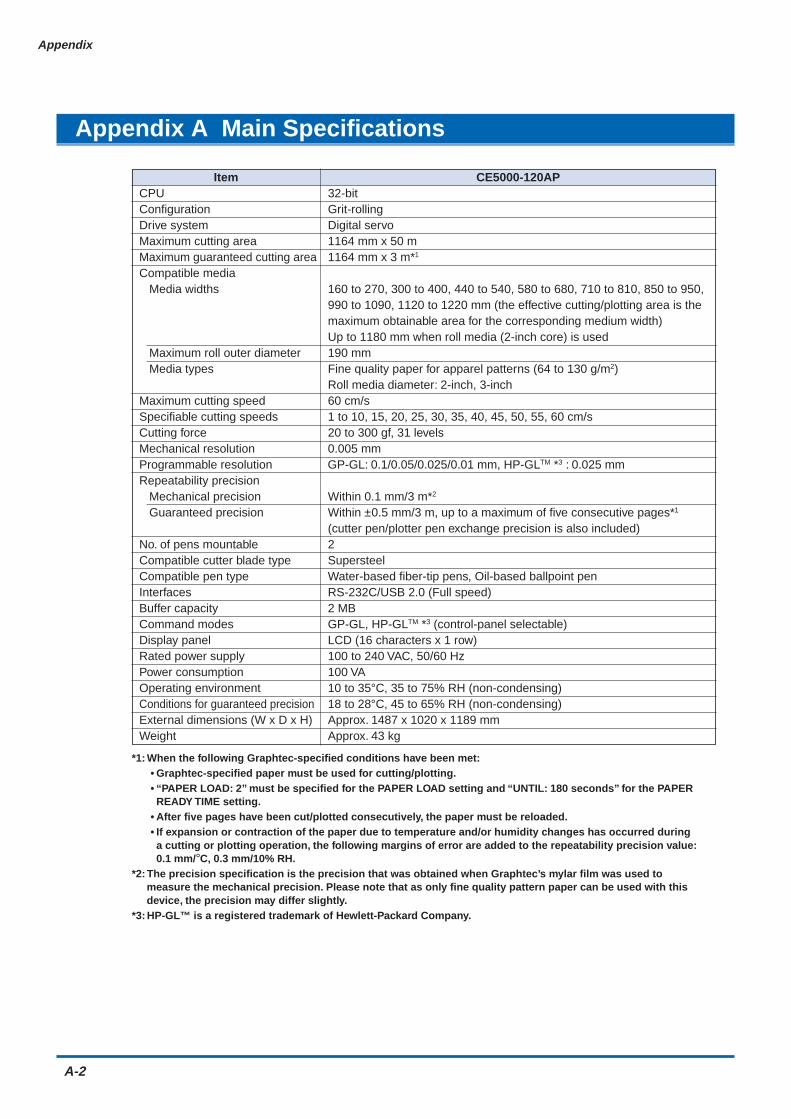
A-2
Appendix
Appendix A Main Specifications
Item CE5000-120APCPU 32-bitConfiguration Grit-rollingDrive system Digital servoMaximum cutting area 1164 mm x 50 mMaximum guaranteed cutting area 1164 mm x 3 m*1
Compatible media Media widths 160 to 270, 300 to 400, 440 to 540, 580 to 680, 710 to 810, 850 to 950,
990 to 1090, 1120 to 1220 mm (the effective cutting/plotting area is themaximum obtainable area for the corresponding medium width)Up to 1180 mm when roll media (2-inch core) is used
Maximum roll outer diameter 190 mm Media types Fine quality paper for apparel patterns (64 to 130 g/m2)
Roll media diameter: 2-inch, 3-inchMaximum cutting speed 60 cm/sSpecifiable cutting speeds 1 to 10, 15, 20, 25, 30, 35, 40, 45, 50, 55, 60 cm/sCutting force 20 to 300 gf, 31 levelsMechanical resolution 0.005 mmProgrammable resolution GP-GL: 0.1/0.05/0.025/0.01 mm, HP-GLTM *3 : 0.025 mmRepeatability precision Mechanical precision Within 0.1 mm/3 m*2
Guaranteed precision Within ±0.5 mm/3 m, up to a maximum of five consecutive pages*1
(cutter pen/plotter pen exchange precision is also included)No. of pens mountable 2Compatible cutter blade type SupersteelCompatible pen type Water-based fiber-tip pens, Oil-based ballpoint penInterfaces RS-232C/USB 2.0 (Full speed)Buffer capacity 2 MBCommand modes GP-GL, HP-GLTM *3 (control-panel selectable)Display panel LCD (16 characters x 1 row)Rated power supply 100 to 240 VAC, 50/60 HzPower consumption 100 VAOperating environment 10 to 35°C, 35 to 75% RH (non-condensing)Conditions for guaranteed precision 18 to 28°C, 45 to 65% RH (non-condensing)External dimensions (W x D x H) Approx. 1487 x 1020 x 1189 mmWeight Approx. 43 kg
*1: When the following Graphtec-specified conditions have been met:• Graphtec-specified paper must be used for cutting/plotting.• “PAPER LOAD: 2” must be specified for the PAPER LOAD setting and “UNTIL: 180 seconds” for the PAPERREADY TIME setting.
• After five pages have been cut/plotted consecutively, the paper must be reloaded.• If expansion or contraction of the paper due to temperature and/or humidity changes has occurred duringa cutting or plotting operation, the following margins of error are added to the repeatability precision value:0.1 mm/°C, 0.3 mm/10% RH.
*2: The precision specification is the precision that was obtained when Graphtec’s mylar film was used tomeasure the mechanical precision. Please note that as only fine quality pattern paper can be used with thisdevice, the precision may differ slightly.
*3: HP-GL™ is a registered trademark of Hewlett-Packard Company.
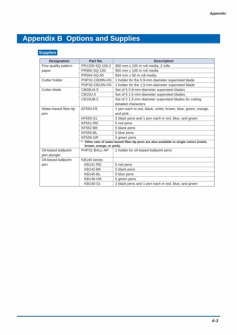
Appendix
A-3
Appendix B Options and Supplies
Supplies
Designation Part No. DescriptionFine quality pattern PR1200-SQ-100-2 950 mm x 100 m roll media, 2 rollspaper PR950-SQ-100 950 mm x 100 m roll media
PR594-SQ-50 594 mm x 50 m roll mediaCutter holder PHP32-CB09N-HS 1 holder for the 0.9-mm diameter supersteel blade
PHP32-CB15N-HS 1 holder for the 1.5-mm-diameter supersteel bladeCutter blade CB09UA-5 Set of 5 0.9-mm-diameter supersteel blades
CB15U-5 Set of 5 1.5-mm-diameter supersteel bladesCB15UB-2 Set of 2 1.5-mm diameter supersteel blades for cutting
detailed charactersWater-based fiber-tip KF550-F8 1 pen each in red, black, violet, brown, blue, green, orange,pen and pink
KF550-S1 2 black pens and 1 pen each in red, blue, and greenKF551-RD 5 red pensKF552-BK 5 black pensKF555-BL 5 blue pensKF556-GR 5 green pens* Other sets of water-based fiber-tip pens are also available in single colors (violet,
brown, orange, or pink).Oil-based ballpoint PHP31-BALL-AP 1 holder for oil-based ballpoint penspen plungerOil-based ballpoint KB140 seriespen KB141-RD 5 red pens
KB142-BK 5 black pens KB145-BL 5 blue pens KB146-GR 5 green pens KB140-S1 2 black pens and 1 pen each in red, blue, and green

A-4
Appendix
Appendix C External Dimensions
1487
1020
1189
Units: mmDimensional accuracy: 5 mm

Appendix
A-5
Appendix D Menu Tree
S E L E C T U S E R
C O M M A N D
R S - 2 3 2 C
P A G E L E N G T H
S E P A R A T O R
T I M E O U T
P A P E R R E A D Y T I M E
P A P E R L O A D
C L E A R B U F F E R
D I S T A N C E A D J U S T
A X I S A L I G N M E N T
P L O T A R E A
E X P A N D
R O T A T E
S O R T
S P A C E R E A R
O F F S E T F O R C E
I N I T . D O W N F O R C E
S T E P P A S S
O F F S E T A N G L E
F _ C U T
L E N G T H U N I T
F E E D & C U T
B L A D E W A R E S E T U P
P E N U P / D O W N
C U T L I N E P A T .
T A N G E N T I A L
I N I T . B
P E N U P S P E E D
I N I T I A L F E E D
A U T O P R E F E E D
A D V A N C E D F U N C .
S E T U P M E N U
T E S T
P E N 1 / 2 A D J
C O P Y
4.2 Clearing the Buffer Memory
4.3 Setting the FEED & CUT function
4.4 Blade Wear Detection (When Blade Wear Setup is On)
4.5 Raising and Lowering the Pen
4.6 Selecting the Type of Perforated Line.
4.7 Setting TANGENTIAL Mode
4.8 Selecting the Blade Tip's Initial Position
4.9 Setting the PEN UP SPEED
4.10 Specifying the INITIAL FEED Length
4.11 Setting AUTO PRE-FEED
4.35 TEST Mode
4.25 Adjusting the Distance Between the Pens
4.26 Cutting/Plotting Using the Buffer Memory (COPY Function)
4.12 Distance Adjustment
4.27 User-specified Settings
4.28 Setting the Format of Data to be Received
4.29 Interface Settings
4.30 Setting the PAGE LENGTH
4.31 Setting the SEPARATOR Function
4.32 Setting the TIMEOUT Function
4.33 Setting the PAPER READY TIME
4.34 Setting the PAPER LOAD Function
4.13 Aligning the Coordinate Axes
4.14 Setting the Cutting/Plotting Area
4.15 Expanding the Cutting/Plotting Area
4.16 Rotating the Coordinate Axes
4.17 Sorting Settings
4.18 Specifying the SPACE REAR Distance
4.19 Setting the OFFSET FORCE (Initial Cutting Force)
4.20 Setting the Initial Down Force
4.21 Setting the STEP PASS
4.22 Setting the OFFSET ANGLE
4.23 Setting the F_CUT Function
4.24 Setting the LENGTH UNIT
(ENTER) key
(ENTER) key
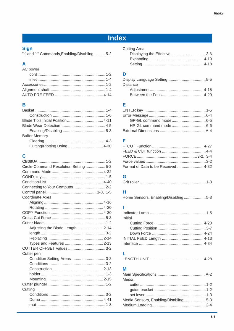
Index
I-1
IndexSign":" and ";" Commands,Enabling/Disabling ..........5-2
AAC power
cord..............................................................1-2inlet ..............................................................1-4
Accessories ........................................................1-2Alignment shaft ..................................................1-4AUTO PRE-FEED ............................................4-14
BBasket ................................................................1-4
Construction ................................................1-6Blade Tip's Initial Position .................................4-11Blade Wear Detection ........................................4-5
Enabling/Disabling .......................................5-3Buffer Memory
Clearing .......................................................4-3Cutting/Plotting Using ................................4-30
CCB09UA .............................................................1-2Circle-Command Resolution Setting ..................5-3Command Mode...............................................4-32COND. key..........................................................1-5Condition-List ...................................................4-40Connecting to Your Computer ............................2-2Control panel ..............................................1-3, 1-5Coordinate Axes
Aligning ......................................................4-16Rotating .....................................................4-20
COPY Function ................................................4-30Cross-Cut Force .................................................5-3Cutter blade ........................................................1-2
Adjusting the Blade Length........................2-14length ...........................................................3-2Replacing...................................................2-14Types and Features ...................................2-13
CUTTER OFFSET Values ..................................3-2Cutter pen
Condition Setting Areas ...............................3-3Conditions....................................................3-2Construction ..............................................2-13holder ...........................................................1-3Mounting ....................................................2-15
Cutter plunger ....................................................1-2Cutting
Conditions....................................................3-2Demo .........................................................4-41mat ...............................................................1-3
Cutting AreaDisplaying the Effective ...............................3-6Expanding..................................................4-19Setting .......................................................4-18
DDisplay Language Setting ..................................5-5Distance
Adjustment .................................................4-15Between the Pens......................................4-29
EENTER key ........................................................1-5Error Message....................................................6-4
GP-GL command mode...............................6-5HP-GL command mode ...............................6-6
External Dimensions ......................................... A-4
FF_CUT Function ...............................................4-27FEED & CUT function ........................................4-4FORCE.......................................................3-2, 3-4Force values .......................................................3-2Format of Data to be Received ........................4-32
GGrit roller ............................................................1-3
HHome Sensors, Enabling/Disabling ....................5-3
IIndicator Lamp ...................................................1-5Initial
Cutting Force .............................................4-23Cutting Position............................................3-7Down Force ...............................................4-24
INITIAL FEED Length ......................................4-13Interface ...........................................................4-34
LLENGTH UNIT .................................................4-28
MMain Specifications ........................................... A-2Media
cutter ............................................................1-2guide bracket ...............................................1-2set lever .......................................................1-3
Media Sensors, Enabling/Disabling....................5-3Medium,Loading.................................................2-4
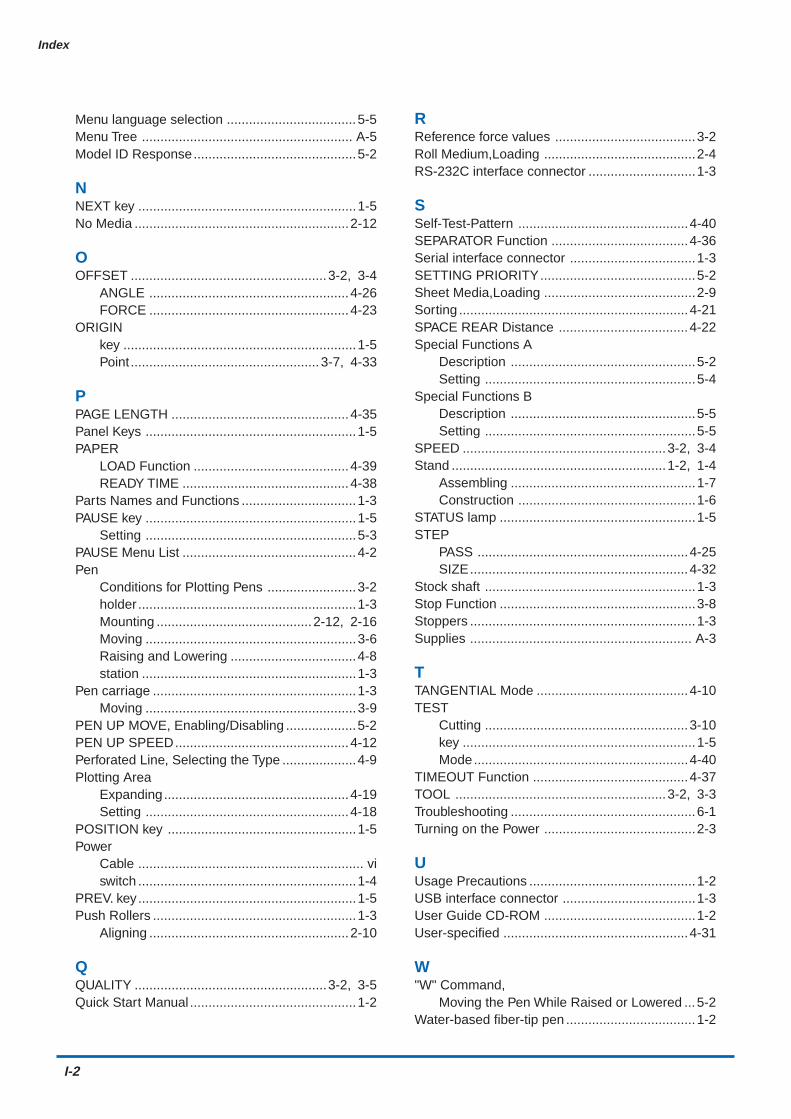
I-2
Index
Menu language selection ...................................5-5Menu Tree ......................................................... A-5Model ID Response............................................5-2
NNEXT key ...........................................................1-5No Media ..........................................................2-12
OOFFSET .....................................................3-2, 3-4
ANGLE ......................................................4-26FORCE ......................................................4-23
ORIGINkey ...............................................................1-5Point ...................................................3-7, 4-33
PPAGE LENGTH ................................................4-35Panel Keys .........................................................1-5PAPER
LOAD Function ..........................................4-39READY TIME .............................................4-38
Parts Names and Functions ...............................1-3PAUSE key .........................................................1-5
Setting .........................................................5-3PAUSE Menu List ...............................................4-2Pen
Conditions for Plotting Pens ........................3-2holder ...........................................................1-3Mounting ..........................................2-12, 2-16Moving .........................................................3-6Raising and Lowering ..................................4-8station ..........................................................1-3
Pen carriage .......................................................1-3Moving .........................................................3-9
PEN UP MOVE, Enabling/Disabling ...................5-2PEN UP SPEED...............................................4-12Perforated Line, Selecting the Type ....................4-9Plotting Area
Expanding..................................................4-19Setting .......................................................4-18
POSITION key ...................................................1-5Power
Cable ............................................................. viswitch ...........................................................1-4
PREV. key...........................................................1-5Push Rollers .......................................................1-3
Aligning ......................................................2-10
QQUALITY ....................................................3-2, 3-5Quick Start Manual .............................................1-2
RReference force values ......................................3-2Roll Medium,Loading .........................................2-4RS-232C interface connector .............................1-3
SSelf-Test-Pattern ..............................................4-40SEPARATOR Function .....................................4-36Serial interface connector ..................................1-3SETTING PRIORITY..........................................5-2Sheet Media,Loading .........................................2-9Sorting ..............................................................4-21SPACE REAR Distance ...................................4-22Special Functions A
Description ..................................................5-2Setting .........................................................5-4
Special Functions BDescription ..................................................5-5Setting .........................................................5-5
SPEED .......................................................3-2, 3-4Stand ..........................................................1-2, 1-4
Assembling ..................................................1-7Construction ................................................1-6
STATUS lamp .....................................................1-5STEP
PASS .........................................................4-25SIZE...........................................................4-32
Stock shaft .........................................................1-3Stop Function .....................................................3-8Stoppers .............................................................1-3Supplies ............................................................ A-3
TTANGENTIAL Mode .........................................4-10TEST
Cutting .......................................................3-10key ...............................................................1-5Mode..........................................................4-40
TIMEOUT Function ..........................................4-37TOOL .........................................................3-2, 3-3Troubleshooting ..................................................6-1Turning on the Power .........................................2-3
UUsage Precautions .............................................1-2USB interface connector ....................................1-3User Guide CD-ROM .........................................1-2User-specified ..................................................4-31
W"W" Command,
Moving the Pen While Raised or Lowered ...5-2Water-based fiber-tip pen ...................................1-2

The specifications, etc., in this manual aresubject to change without notice.
CE5000AP-UM-152April 20, 2007 1st edition-01
GRAPHTEC CORPORATION

503-10 Shinano-cho, Totsuka-ku,�Yokohama 244-8503, Japan�Tel : +81 (045) 825-6250�Fax : +81 (045) 825-6396�Email : [email protected]�Web : www.graphteccorp.com�
Printed in Japan