ceiling configuration report
TRANSCRIPT
design advice
passive systems
design analysis
low energy services
March 03
AESY820000\0\2\EKA30304
Melbourne City Council Offices (CH2)
Chilled Panel Ceiling Configuration Report
Prepared for: Melbourne City Council
Prepared by: Advanced Environmental Concepts Pty Ltd ACN 075 117 243 Level 1, 41 McLaren Street North Sydney NSW 2060
Chilled Panel Ceiling Configuration Report Executive Summary
AESY820000\0\2\EKA30304 © Advanced Environmental Concepts 31/03/2003 i
EXECUTIVE SUMMARY
The main purpose of this report is to investigate various options proposed for the location of the chilled panels on the curved soffit within the new Melbourne City Council offices. Each chilled panel location option is to be considered with respect to:
• Air flows • Air Temperature • Mean Radiant Temperatures • Resultant temperatures • Occupant Comfort Levels
Two options were considered: Option 1 which incorporated the chilled panel as a continuous panel across the lowest portion of the curved ceiling and Option 2 which incorporated the chilled panel to sit in separate parts on the sloped portion of the curved ceiling. The model results indicated that the chilled panel position in Option 2 is the preferred option for the development due to the superior thermal performance results, particularly air flow and air temperature.

Chilled Panel Ceiling Configuration Report Table of Contents
AESY820000\0\2\EKA30304 © Advanced Environmental Concepts 31/03/2003 ii
TABLE OF CONTENTS
EXECUTIVE SUMMARY I
TABLE OF CONTENTS II
LIST OF FIGURES III
1 INTRODUCTION 1
2 APPROACH 2 2.1 Computer Modelling 2 2.2 Mechanical System 2 2.3 Design Inputs 2 2.4 Air flows 3 2.5 Air Temperature 3 2.6 Mean Radiant Temperatures 3 2.7 Resultant Temperatures 3 2.8 Occupant Comfort Levels 3
3 DESIGN CONCEPTS 4 3.1 Options 4
4 RESULTS 6 4.1 Air flows 6 4.2 Air Temperature 8 4.3 Mean Radiant Temperatures 10 4.4 Resultant Temperatures 11 4.5 Occupant Comfort Levels (Predicted Percentage Dissatisfied) 12 4.6 Option 2 Revised Relief Air Outlet Results 13
5 CONCLUSION/RECOMMENDATIONS 14 APPENDIX A
Date
Revision and Status
Author
Project Team Leader

Chilled Panel Ceiling Configuration Report List of Figures
AESY820000\0\2\EKA30304 © Advanced Environmental Concepts 31/03/2003 iii
LIST OF FIGURES
Figure 1: Option 1 Chilled panel on lowest portion of ceiling ...............................................................4 Figure 2: Model of Option 1.........................................................................................................................4 Figure 3: Option 2 Chilled panel on sloped portion of ceiling ..............................................................5 Figure 4: Model of Option2..........................................................................................................................5 Figure 5: Option1 Air Flow Pattern ..............................................................................................................6 Figure 6: Option 2 Air Flow Pattern .............................................................................................................6 Figure 7: Option 1 Air Temperatures...........................................................................................................8 Figure 8: Option 2 Air Temperatures...........................................................................................................8 Figure 9: Option 1 Mean Radiant Temperature.....................................................................................10 Figure 10: Option 2 Mean Radiant Temperature...................................................................................10 Figure 11: Option 1 Resultant Temperature ............................................................................................11 Figure 12: Option 2 Resultant Temperature ............................................................................................11 Figure 13: Option 1 PPD..............................................................................................................................12 Figure 14: Option 2 PPD..............................................................................................................................12 Figure 15: Option 2 Revised Relief Air Outlet Model..............................................................................16 Figure 16: Option 2 Revised Relief Air Outlet Air Flow Pattern .............................................................16 Figure 17: Option 2 Revised Relief Air Outlet Air Temperature ............................................................17 Figure 18: Option 2 Revised Relief Air Outlet Mean Radiant Temperature.......................................17 Figure 19: Option 2 Revised Relief Air Outlet Resultant Temperature ................................................18 Figure 20: Option 2 Revised Relief Air Outlet PPD..................................................................................18
Chilled Panel Ceiling Configuration Report Introduction
AESY820000\0\2\EKA30304 © Advanced Environmental Concepts 31/03/2003 1
1 INTRODUCTION
One of the design objectives of the Melbourne City Council development is to create a working environment with improved indoor air quality, improved ventilation efficiency and improved thermal comfort when compared to a typical office building, whilst being low in energy consumption. The Melbourne City Council Development is to incorporate a unique wave pattern ceiling within the office spaces. The ceiling will be a visual focus point of the office space and consequently the co-ordination of the services on the ceiling is important not only from a thermal performance perspective, but also aesthetically. The main purpose of this report is to investigate various options proposed for the location of the chilled panels on the curved ceiling within the Melbourne City Council development. Each chilled panel location option is to be considered with respect to:
• Air flows • Air Temperature • Mean Radiant Temperatures • Resultant temperatures • Occupant Comfort Levels
Recommendations made within this report are to assist the design team in the ceiling co-ordination of services.
Chilled Panel Ceiling Configuration Report Approach
AESY820000\0\2\EKA30304 © Advanced Environmental Concepts 31/03/2003 2
2 APPROACH
2.1 Computer Modelling
The systems proposed were modelled using a computational fluid dynamics (CFD) ‘Ambiens” program created for analysing building microclimates. Ambiens simulates the air flow and temperature across a two-dimensional building space by repeatedly solving a set of equations that represent the flow and temperature, until the results approach an accurate solution.
2.2 Mechanical System
The following mechanical system was modelled: Supply air is distributed to the office floor via a displacement system. The displacement system is 100% outside air supplied to the office space from a floor plenum via displacement diffusers. Relief air from each floor will be exhausted passively via ceiling mounted relief air grilles. Supplementing the displacement system is a combination of chilled beams and ceiling panels. Chilled beams are located above vision panels around the perimeter to cater for varying solar and transmission loads. Chilled ceiling panels are located throughout the space and will cater for the total internal space loads. For this investigation we have modelled an internal space within the office, thus the displacement ventilation system is modelled in conjunction with chilled ceiling panels.
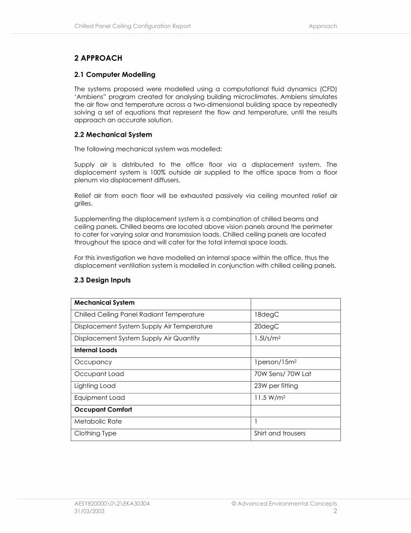
2.3 Design Inputs
Mechanical System
Chilled Ceiling Panel Radiant Temperature 18degC
Displacement System Supply Air Temperature 20degC
Displacement System Supply Air Quantity 1.5l/s/m2
Internal Loads
Occupancy 1person/15m2
Occupant Load 70W Sens/ 70W Lat
Lighting Load 23W per fitting
Equipment Load 11.5 W/m2
Occupant Comfort
Metabolic Rate 1
Clothing Type Shirt and trousers
Chilled Panel Ceiling Configuration Report Approach
AESY820000\0\2\EKA30304 © Advanced Environmental Concepts 31/03/2003 3
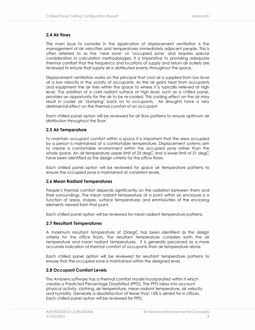
2.4 Air flows
The main issue to consider in the application of displacement ventilation is the management of air velocities and temperatures immediately adjacent people. This is often referred to as the ‘near zone’ or ‘occupied zone’ and requires special consideration in calculation methodologies. It is imperative to providing adequate thermal comfort that the frequency and locations of supply and return air outlets are reviewed to ensure that supply air is distributed evenly throughout the space. Displacement ventilation works on the principal that cool air is supplied from low level at a low velocity in the vicinity of occupants. As the air gains heat from occupants and equipment the air rises within the space to where it is typically relieved at high level. The addition of a cold radiant surface at high level, such as a chilled panel, provides an opportunity for the air to be re-cooled. This cooling effect on the air may result in cooler air ‘dumping’ back on to occupants. Air draughts have a very detrimental effect on the thermal comfort of an occupant. Each chilled panel option will be reviewed for air flow patterns to ensure optimum air distribution throughout the floor.
2.5 Air Temperature
To maintain occupant comfort within a space it is important that the area occupied by a person is maintained at a comfortable temperature. Displacement systems aim to create a comfortable environment within the occupied zone rather than the whole space. An air temperature upper limit of 25 degC and a lower limit of 21 degC have been identified as the design criteria for the office floors. Each chilled panel option will be reviewed for space air temperature patterns to ensure the occupied zone is maintained at consistent levels.
2.6 Mean Radiant Temperatures
People’s thermal comfort depends significantly on the radiation between them and their surroundings. The mean radiant temperature at a point within an enclosure is a function of areas, shapes, surface temperatures and emmissivities of the enclosing elements viewed from that point. Each chilled panel option will be reviewed for mean radiant temperature patterns.
2.7 Resultant Temperatures
A maximum resultant temperature of 23degC has been identified as the design criteria for the office floors. The resultant temperature considers both the air temperature and mean radiant temperatures. It is generally perceived as a more accurate indication of thermal comfort of occupants than air temperature alone. Each chilled panel option will be reviewed for resultant temperature patterns to ensure that the occupied zone is maintained within the designed level.
2.8 Occupant Comfort Levels
The Ambiens software has a thermal comfort model incorporated within it which creates a Predicted Percentage Dissatisfied (PPD). The PPD takes into account physical activity, clothing, air temperature, mean radiant temperature, air velocity and humidity. Generally a dissatisfaction of fewer than 15% is aimed for in offices. Each chilled panel option will be reviewed for PPD.
Chilled Panel Ceiling Configuration Report Design Concepts
AESY820000\0\2\EKA30304 © Advanced Environmental Concepts 31/03/2003 4
3 DESIGN CONCEPTS
3.1 Options
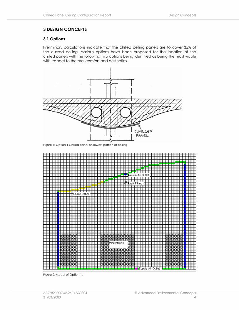
Preliminary calculations indicate that the chilled ceiling panels are to cover 35% of the curved ceiling. Various options have been proposed for the location of the chilled panels with the following two options being identified as being the most viable with respect to thermal comfort and aesthetics.
Figure 1: Option 1 Chilled panel on lowest portion of ceiling
Figure 2: Model of Option 1.

Chilled Panel Ceiling Configuration Report Design Concepts
AESY820000\0\2\EKA30304 © Advanced Environmental Concepts 31/03/2003 5
Figure 3: Option 2 Chilled panel on sloped portion of ceiling
Figure 4: Model of Option2
As detailed in the above figures, each option is modelled as a half-bay section (4.1m wide) incorporating a hanging lighting fitting, a return air grille in the ceiling space and a floor supply air diffuser adjacent to an area modelled as an occupied workstation.

Chilled Panel Ceiling Configuration Report Results
AESY820000\0\2\EKA30304 © Advanced Environmental Concepts 31/03/2003 6
4 RESULTS
4.1 Air flows
Figure 5: Option1 Air Flow Pattern
Figure 6: Option 2 Air Flow Pattern
The above results indicate that the lower chilled ceiling panels of Option 1 are creating a downward flow of air along the ceiling towards the lowest point of the curved ceiling. As air meets from both sides of the curved ceiling the air flows
Chilled Panel Ceiling Configuration Report Results
AESY820000\0\2\EKA30304 © Advanced Environmental Concepts 31/03/2003 7
converge and drop, creating a “dumping” effect which may produce down draughts. Down draughts will have a detrimental effect on an occupant’s thermal comfort, despite air temperature, as they usually occur on the back of an occupant’s neck which is an area known to be particularly sensitive to air movement. The Option 2 air flow pattern is more uniform than Option 1, with consistent air velocities and even air distribution.

Chilled Panel Ceiling Configuration Report Results
AESY820000\0\2\EKA30304 © Advanced Environmental Concepts 31/03/2003 8
4.2 Air Temperature
Figure 7: Option 1 Air Temperatures
Figure 8: Option 2 Air Temperatures
The figures above illustrates that the lower ceiling position of the chilled panels in Option 1 contribute towards a lower air temperature directly below the chilled panels. The temperature increases as you move away from the vicinity of the panel. The occupied zone air temperature has a mixed gradient of temperatures.

Chilled Panel Ceiling Configuration Report Results
AESY820000\0\2\EKA30304 © Advanced Environmental Concepts 31/03/2003 9
Option 2, however, although having slightly higher temperatures, is evenly distributed across the office floor. The occupied zone has a somewhat higher temperature than the remaining office floor area, which is as expected for a displacement ventilation system.

Chilled Panel Ceiling Configuration Report Results
AESY820000\0\2\EKA30304 © Advanced Environmental Concepts 31/03/2003 10
4.3 Mean Radiant Temperatures
Figure 9: Option 1 Mean Radiant Temperature
Figure 10: Option 2 Mean Radiant Temperature
From the above figures we note that the lower chilled panel position of Option 1 results in a lower mean radiant temperature extending to the occupied zone. The cooler radiant temperatures off the floor surfaces are the result of the floor surface temperature being low due to the supply air plenum below.

Chilled Panel Ceiling Configuration Report Results
AESY820000\0\2\EKA30304 © Advanced Environmental Concepts 31/03/2003 11
4.4 Resultant Temperatures
Figure 11: Option 1 Resultant Temperature
Figure 12: Option 2 Resultant Temperature
Option 1 indicates a lower resultant temperature below the chilled panel than Option 2. This would be due to the increased radiant effect of the chilled panel. Both options indicate similar resultant temperatures within the occupied zone.

Chilled Panel Ceiling Configuration Report Results
AESY820000\0\2\EKA30304 © Advanced Environmental Concepts 31/03/2003 12
4.5 Occupant Comfort Levels (Predicted Percentage Dissatisfied)
Figure 13: Option 1 PPD
Figure 14: Option 2 PPD
Option 1 shows a higher PPD directly below the chilled panels than Option 2. Option 2 shows a consistently low PPD across the whole floor with an even lower percentage dissatisfied within the occupied zone.

Chilled Panel Ceiling Configuration Report Results
AESY820000\0\2\EKA30304 © Advanced Environmental Concepts 31/03/2003 13
4.6 Option 2 Revised Relief Air Outlet Results
Option 2 was remodelled with a revised relief air outlet position to determine whether the relief air outlet position had a significant effect on the air flows and thermal performance of the space. The results are contained within Appendix A. The air flow patterns, mean radiant temperatures, resultant temperatures and PPD’s are very similar for both relief air outlet positions, however the warmer air temperature zone within the occupied area is slightly larger for the lower positioned relief air grille.
Chilled Panel Ceiling Configuration Report Conclusion/Recommendations
AESY820000\0\2\EKA30304 © Advanced Environmental Concepts 31/03/2003 14
5 CONCLUSION/RECOMMENDATIONS
Comparing the lower Chilled Panel position of Option 1 to the higher chilled panel position of Option 2 we obtained the following results:
• Option 2 has the superior air distribution of the two options with Option 1 potentially forming air draughts from the lowest point of the curved ceiling.
• Option 2 has a more uniform air temperature across the floor with a higher air temperature in the occupied zone. Option 1 has lower air temperatures below the chilled panel with a mixed gradient of air temperature across the office floor.
• Option 1 has a lower Mean Radiant Temperature below the chilled panel extending to the occupied zone. The lower Mean Radiant Temperature from Option 2’s chilled panels does not extend to the occupied zone.
• Option 1 has a lower resultant temperature below the chilled panels than Option 2.
• Option 1 has a higher Percentage of People Dissatisfied (PPD) directly below the chilled panels than Option 2. Option 2 has a uniform PPD across the office floor with a lower PPD recorded in the occupied zone.
The above results indicate that the chilled panel position in Option 2 is the preferred option for the development due to the superior thermal performance results outlined above. The results obtained from the investigation of relocating the relief air grille position in the Option 2 model did not result in any major changes to the Option 2 thermal comfort parameters. Subsequently it may be recommended that either relief air outlet position may be considered for the project.

Chilled Panel Ceiling Configuration Report Appendix A
AESY820000\0\2\EKA30304 © Advanced Environmental Concepts 31/03/2003 15
APPENDIX A
OPTION 2 REVISED RELIEF AIR OUTLET RESULTS

Chilled Panel Ceiling Configuration Report Appendix A
AESY820000\0\2\EKA30304 © Advanced Environmental Concepts 31/03/2003 16
Figure 15: Option 2 Revised Relief Air Outlet Model
Figure 16: Option 2 Revised Relief Air Outlet Air Flow Pattern

Chilled Panel Ceiling Configuration Report Appendix A
AESY820000\0\2\EKA30304 © Advanced Environmental Concepts 31/03/2003 17
Figure 17: Option 2 Revised Relief Air Outlet Air Temperature
Figure 18: Option 2 Revised Relief Air Outlet Mean Radiant Temperature

Chilled Panel Ceiling Configuration Report Appendix A
AESY820000\0\2\EKA30304 © Advanced Environmental Concepts 31/03/2003 18
Figure 19: Option 2 Revised Relief Air Outlet Resultant Temperature
Figure 20: Option 2 Revised Relief Air Outlet PPD