celestial navigation on the surface of mars · celestial navigation has been used reliably on earth...
TRANSCRIPT
U.S.N.A --- Trident Scholar project report; no. 284 (2001)
CELESTIAL NAVIGATION ON THE SURFACE OF MARS
By
Midshipman Benjamin P. Malay, Class of 2001 United States Naval Academy
Annapolis, Maryland
____________________________________________
Certification of Adviser Approval
Professor Richard P. Fahey Aerospace Engineering Department
_____________________________________________
___________________
Acceptance for the Trident Scholar Committee
Professor Joyce E. Shade Chair, Trident Scholar Committee
_____________________________________________
___________________
USNA-1531-2

Form SF298 Citation Data
Report Date("DD MON YYYY") 07052001
Report TypeN/A
Dates Covered (from... to)("DD MON YYYY")
Title and Subtitle Celestial navigation on the surface of Mars
Contract or Grant Number
Program Element Number
Authors Malay, Benjamin P.
Project Number
Task Number
Work Unit Number
Performing Organization Name(s) and Address(es) US Naval Academy Annapolis, MD 21402
Performing Organization Number(s)
Sponsoring/Monitoring Agency Name(s) and Address(es) Monitoring Agency Acronym
Monitoring Agency Report Number(s)
Distribution/Availability Statement Approved for public release, distribution unlimited
Supplementary Notes
Abstract
Subject Terms
Document Classification unclassified
Classification of SF298 unclassified
Classification of Abstract unclassified
Limitation of Abstract unlimited
Number of Pages 34

REPORT DOCUMENTATION PAGE
Form ApprovedOMB No. 074-0188
Public reporting burden for this collection of information is estimated to average 1 hour per response, including g the time for reviewing instructions, searching existing datasources, gathering and maintaining the data needed, and completing and reviewing the collection of information. Send comments regarding this burden estimate or any otheraspect of the collection of information, including suggestions for reducing this burden to Washington Headquarters Services, Directorate for Information Operations and Reports,1215 Jefferson Davis Highway, Suite 1204, Arlington, VA 22202-4302, and to the Office of Management and Budget, Paperwork Reduction Project (0704-0188), Washington, DC20503.
1. AGENCY USE ONLY (Leave blank) 2. REPORT DATE
7 May 20013. REPORT TYPE AND DATE COVERED
4. TITLE AND SUBTITLE
Celestial navigation on the surface of Mars
6. AUTHOR(S)
Malay, Benjamin P.
5. FUNDING NUMBERS
7. PERFORMING ORGANIZATION NAME(S) AND ADDRESS(ES) 8. PERFORMING ORGANIZATION REPORT NUMBER
9. SPONSORING/MONITORING AGENCY NAME(S) AND ADDRESS(ES) 10. SPONSORING/MONITORING AGENCY REPORT NUMBER
US Naval AcademyAnnapolis, MD 21402
Trident Scholar project report no.284 (2001)
11. SUPPLEMENTARY NOTES
12a. DISTRIBUTION/AVAILABILITY STATEMENT
This document has been approved for public release; its distributionis UNLIMITED.
12b. DISTRIBUTION CODE
13. ABSTRACT:A simple, accurate, and autonomous method of finding position on the surface of Mars currently does not exist. The goal ofthis project is to develop a celestial navigation process that will fix a position on Mars with 100-meter accuracy. Thismethod requires knowing the position of the stars and planets referenced to the Martian surface with one arcsecond accuracy. This information is contained in an ephemeris known as the Arenautical Almanac (from Ares, the god of war). NavalObservatory Vector Astrometry Subroutines (NOVAS) form the basis of the code used to generate the almanac. Planetary positiondata come the JPL DE405 Planetary Ephemeris. The theoretical accuracy of the almanac is determined mathematically andcompared with the Ephemeris for Physical Observations of Mars contained in the Astronomical Almanac. A preliminary design ofan autonomous celestial navigation system is presented. Recommendations of how to integrate celestial navigation into NASA=scurrent Mars exploration program are also discussed. This project is a useful and much-needed first step towardsestablishing celestial navigation as a practical way to find position on the surface of Mars.
15. NUMBER OF PAGES66
14. SUBJECT TERMSMars; navigation; celestial; ephemeris; surface
16. PRICE CODE
17. SECURITY CLASSIFICATION OF REPORT
18. SECURITY CLASSIFICATION OF THIS PAGE
19. SECURITY CLASSIFICATION OF ABSTRACT
20. LIMITATION OF ABSTRACT
NSN 7540-01-280-5500 Standard Form 298 (Rev.2-89) Prescribed by ANSI Std. Z39-18

1
Abstract
A simple, accurate, and autonomous method of finding position on the surface of Mars currently does not exist. The goal of this project is to develop a celestial navigation process that will fix a position on Mars with 100-meter accuracy. This method requires knowing the position of the stars and planets referenced to the martian surface with one arcsecond accuracy. This information is contained in an ephemeris known as the Arenautical Almanac (from Ares, the god of war). Naval Observatory Vector Astrometry Subroutines (NOVAS) form the basis of the code used to generate the almanac. Planetary position data come from the JPL DE405 Planetary Ephemeris. The theoretical accuracy of the almanac is determined mathematically and compared with the Ephemeris for Physical Observations of Mars contained in the Astronomical Almanac. A preliminary design of an autonomous celestial navigation system is presented. Recommendations of how to integrate celestial navigation into NASA’s current Mars exploration program are also discussed. This project is a useful and much-needed first step towards establishing celestial navigation as a practical way to find position on the surface of Mars. Keywords: MARS, NAVIGATION, CELESTIAL, EPHEMERIS, SURFACE
2
Table of Contents Page Abstract 1 List of Figures 3 1.1 Introduction 4 1.2 Goals 4 2.0 Background and Theory 4 2.1 The Navigation Problem 4 2.2 Modern Celestial Navigation 5 2.3 Basic Celestial Navigation Principles 6 3.1 Development of the Almanac 7 3.2 Basic Process 7 3.3 Time Scales 8 3.4 Areocentric Position 9 3.5 Light-Time Correction 10 3.6 Aberration 11 3.7 Gravitational Light Deflection 12 3.8 Coordinate Frames 13 3.9 Coordinate Frame Rotation and Precession 14 3.10 Nutation 15 3.11 Spherical Coordinate Systems 17 3.12 NOVAS 18 4.0 Results 19 4.1 Arenautical Almanac 19 4.2 Accuracy of the Arenautical Almanac 20 4.2.1 Theoretical Accuracy 20 4.2.2 Comparison with Ephemeris for Physical Observations 23 4.3 Overall Accuracy Assessment 24 5.0 Next Steps 25 5.1 Atmospheric Effects 25 5.2 Preliminary Design of an Autonomous Celestial Navigation System on Mars 26 5.3 Integrating Celestial Navigation into NASA’s Mars Exploration Initiative 28 6.0 Summary 29 7.0 Acknowledgements 30 References 31 Appendix A 33 Appendix B 34 Appendix C 36 Appendix D 37
3
List of Figures Page Figure 1. Circles of Equal Altitude 6 Figure 2. The Celestial Fix 7 Table 1. Predictions of ∆T for 2001 9 Figure 3. Interpolation of ∆T for 2001.0-2002.0 9 Figure 4. Areocentric Position 10 Figure 5. Light-Time Correction 11 Figure 6. Aberration 11 Figure 7. Gravitational Light Deflection 12 Figure 8. Relationship between J2000.0 and M-MMEIAUD frames 14 Figure 9. Nutation 16 Figure 10. Earth Nutation 16 Figure 11. Mars Nutation 16 Figure 12. Relationship between angular measurements on Mars 18 Table 2. Arenautical Almanac Output of Earth, “marsplan.f” 19 Table 3. Arenautical Almanac Output of Navigational Stars, “marsstar.f” 20 Table 4. Comparison between Arenautical Almanac and Ephemeris for 24 Physical Observations Figure 13. Atmospheric Refraction 25
4
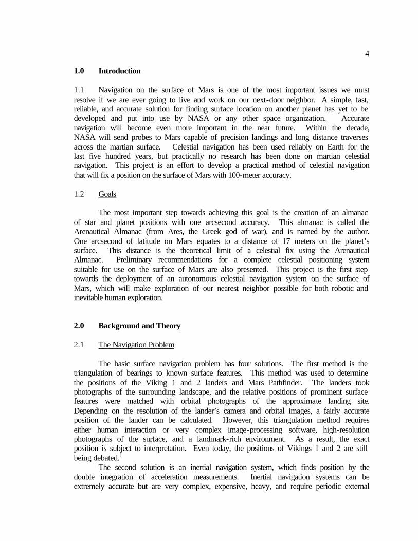
1.0 Introduction 1.1 Navigation on the surface of Mars is one of the most important issues we must resolve if we are ever going to live and work on our next-door neighbor. A simple, fast, reliable, and accurate solution for finding surface location on another planet has yet to be developed and put into use by NASA or any other space organization. Accurate navigation will become even more important in the near future. Within the decade, NASA will send probes to Mars capable of precision landings and long distance traverses across the martian surface. Celestial navigation has been used reliably on Earth for the last five hundred years, but practically no research has been done on martian celestial navigation. This project is an effort to develop a practical method of celestial navigation that will fix a position on the surface of Mars with 100-meter accuracy.
1.2 Goals
The most important step towards achieving this goal is the creation of an almanac of star and planet positions with one arcsecond accuracy. This almanac is called the Arenautical Almanac (from Ares, the Greek god of war), and is named by the author. One arcsecond of latitude on Mars equates to a distance of 17 meters on the planet’s surface. This distance is the theoretical limit of a celestial fix using the Arenautical Almanac. Preliminary recommendations for a complete celestial positioning system suitable for use on the surface of Mars are also presented. This project is the first step towards the deployment of an autonomous celestial navigation system on the surface of Mars, which will make exploration of our nearest neighbor possible for both robotic and inevitable human exploration. 2.0 Background and Theory 2.1 The Navigation Problem
The basic surface navigation problem has four solutions. The first method is the
triangulation of bearings to known surface features. This method was used to determine the positions of the Viking 1 and 2 landers and Mars Pathfinder. The landers took photographs of the surrounding landscape, and the relative positions of prominent surface features were matched with orbital photographs of the approximate landing site. Depending on the resolution of the lander’s camera and orbital images, a fairly accurate position of the lander can be calculated. However, this triangulation method requires either human interaction or very complex image-processing software, high-resolution photographs of the surface, and a landmark-rich environment. As a result, the exact position is subject to interpretation. Even today, the positions of Vikings 1 and 2 are still being debated.1
The second solution is an inertial navigation system, which finds position by the double integration of acceleration measurements. Inertial navigation systems can be extremely accurate but are very complex, expensive, heavy, and require periodic external

5
position updates that are at least as accurate as the inertial navigation system itself.2 Electronic ranging, such as the Global Positioning System (GPS) or Doppler ranging using NASA’s Deep Space Network (DSN), is the third method of navigation. The DSN is composed of several very large and expensive parabolic dish receivers that are also being used for many other NASA missions. Dedicating these resources to surface navigation on Mars is not possible, but they can be used for periodic position updates.
A GPS-like system is extremely accurate, provides a three-dimensional fix, requires little human interaction, and the receiving units are small and inexpensive. Deploying such as system requires an entire navigation infrastructure, and this option becomes extremely expensive if the infrastructure has to be built on Mars. The Jet Propulsion Laboratory in Pasadena, California is presently designing the precursor to such a global positioning system. Funding is scarce, and only one dedicated navigation satellite, if any, will be launched in the foreseeable future. This satellite will provide an accurate three-dimensional fix, but requires several passes over a surface asset to do so. This NASA mission is still in the conceptual design stage and may not be in place for another decade. However, NASA also plans to fly a small electronic ranging payload on each scientific orbiter it sends to Mars, including launch opportunities in 2001 and 2005. A lander on the surface will be able to accurately fix its position using signals from these orbiters, but again, it will take several passes overhead, and surface coverage will be highly variable.3
Celestial navigation, the fourth method, is a very attractive solution for navigation on Mars, especially in the near term while the electronic navigation infrastructure is being deployed. It is simple, accurate, reliable, inexpensive, practically independent of all external inputs, and can be made autonomous. Celestial navigation theory works the same way on Mars as it does on Earth. A surface asset coupled with a high-resolution camera, an instrument that measures the direction of the local vertical, and a computer that can generate the fix will be able to determine its position independently of ranging signals from orbiting satellites or human operators back on Earth. While the deployment of a GPS-like system is the best long-term solution of the navigation problem on Mars, it will be a decade or more before it is in place. Celestial navigation could provide the same service in the near future and provide an independent backup of GPS if and when it is finally deployed.
2.2 Modern Celestial Navigation
In a parallel development, the U.S. Navy has also recognized a need for a navigation system to backup GPS. By law, all Navy ships must have two independent means for determining position. An increasing reliance on the accurate but vulnerable GPS system has concerned naval policy makers. This situation has brought about a renaissance of celestial navigation.4 Dr. George Kaplan of the U.S. Naval Observatory has developed a new rigorous celestial navigation algorithm that is much more accurate than previous sight reduction methods. These algorithms are coded in the STELLA software package for use aboard U.S. naval ships. The algorithms maintain one arcsecond precision throughout the process, and final accuracy of the calculation is limited by the quality of the observations. The observations themselves are currently the
6
largest source of error in celestial navigation, since they are still taken with a hand-held sextant on the deck of a rolling ship. However, if the STELLA code is coupled with a modern automated star imager and an instrument that measures the local vertical, the full capability of modern celestial navigation can be realized.5 2.3 Basic Celestial Navigation Principles
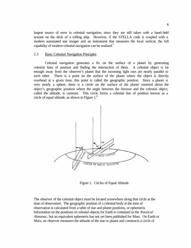
Celestial navigation generates a fix on the surface of a planet by generating
celestial lines of position and finding the intersection of them. A celestial object is far enough away from the observer’s planet that the incoming light rays are nearly parallel to each other. There is a point on the surface of the planet where the object is directly overhead at a given time; this point is called the geographic position. Since a planet is very nearly a sphere, there is a circle on the surface of the planet centered about the object’s geographic position where the angle between the horizon and the celestial object, called the altitude, is constant. This circle forms a celestial line of position known as a circle of equal altitude, as shown in Figure 1.6
The observer of the celestial object must be located somewhere along that circle at the time of observation. The geographic position of a celestial body at the time of observation is calculated from a table of star and planet positions, or ephemeris. Information on the positions of celestial objects for Earth is contained in the Nautical Almanac, but an equivalent ephemeris has not yet been published for Mars. On Earth or Mars, an observer measures the altitude of the star or planet and constructs a circle of
Figure 1. Circles of Equal Altitude

7
equal altitude about the geographic position. This is done for several different bodies. The circles will all intersect each other at a point, and this intersection is the observer’s exact position, as shown in Figure 2.7
3.0 Development of the Almanac 3.1 The Arenautical Almanac contains the positions of the navigable planets and stars referenced to the center of Mars. The concept of this martian almanac is not entirely original; it was worked on briefly during the Viking program by Dr. George Kaplan and Dr. Kenneth Seidelmann of the U.S. Naval Observatory. However, no known documentation of their work exists. I came up with the idea of a navigational almanac for Mars independently nearly twenty-five years later and was lucky enough to meet with Dr. Kaplan and Dr. Seidelmann on several occasions. They have both offered guidance and support, and I am benefiting from their expertise. 3.2 Basic Process The positions of the stars and planets are known with great accuracy with respect to the Earth. The goal of this project is to reference these positions to Mars, and this task can be accomplished mathematically while still maintaining nearly the same accuracy as in the original data. The first step of this process is to generate the areocentric positions (positions referenced to the center of Mars) of the navigable celestial objects, which
Figure 2. The Celestial Fix
8
requires several intermediate steps and corrections. The next step is to transform the coordinates of the objects from an earth-based frame to a Mars-based frame. This transformation is accomplished using a rotation matrix. A detailed description each of these steps is included in the following sections. The algorithm shown applies equally well to both planetary and stellar positions. The calculations in the algorithm are all Cartesian vector-based, even though the observer will ultimately measure an object’s angular position in spherical coordinates. Cartesian vectors are a modern approach to celestial navigation and positional astronomy. Historically, most calculations of these types have been done using spherical trigonometry, not because it is more accurate, but because the calculations can be done by hand, albeit laboriously, with logarithmic and trigonometric math tables. The vector approach is more rigorous than spherical trigonometry and much easier to understand conceptually. The vector approach is now practical as well with the advent of high-speed personal computers. All the calculations required by the almanac, even for distant stars, are done with vector-based algorithms and converted into angular quantities only during the last step. 3.3 Time Scales Since the final users of these data will be located on Earth in the foreseeable future, the most convenient timescale is a terrestrial one. Once the users of the almanac are on Mars, the almanac should be transformed into a martian time system. Several viable martian time systems have been proposed, but none of them have been accepted by the astronomical community. Until that point, the best timescale for the Arenautical Almanac is Universal Time (UT1). UT1 is tied to the diurnal motion of the stars by an equation relating it to Greenwich Mean Sidereal Time (GMST). GMST can be measured directly by meridian transits and interferometer observations of distant radio sources. UT1 is the best timescale for a navigational almanac because it is tied to the position of the stars and the rotation of Earth. UT1 is used as the time argument in the Nautical Almanac, as well as the Arenautical Almanac. The most readily available time scale on Earth is Coordinated Universal Time (UTC), which forms the basis for all civil time systems. However, UTC is simply a convenient atomic timescale and is not adaptable for use in solar system dynamics. UTC is kept to within 0.90 seconds of UT1 through the addition or subtraction of leap seconds when the need arises. The difference between UT1 and UTC is known as DUT1 and is broadcast with the UTC time signal. DUT1 is also published in the International Earth Rotation Service (IERS) Bulletin D. The value of DUT1 is variable and non-linear and subsequently cannot be predicted.8 Two other important time scales are used in the Arenautical Almanac. Barycentric Dynamical Time (TDB) is the time variable of the equations of motions of the planets about the barycenter of the solar system. The barycenter is the center of mass of the solar system and is near the center of the sun, but the actual position varies over time. TDB is a theoretical timescale used to predict where the planets will be in the future. Terrestrial Dynamical Time (TT) is another theoretical timescale used in the calculation of geocentric ephemerides of solar system bodies. TT is an intermediate time argument in many of the subroutines used to produce the Arenautical Almanac.9 The
9
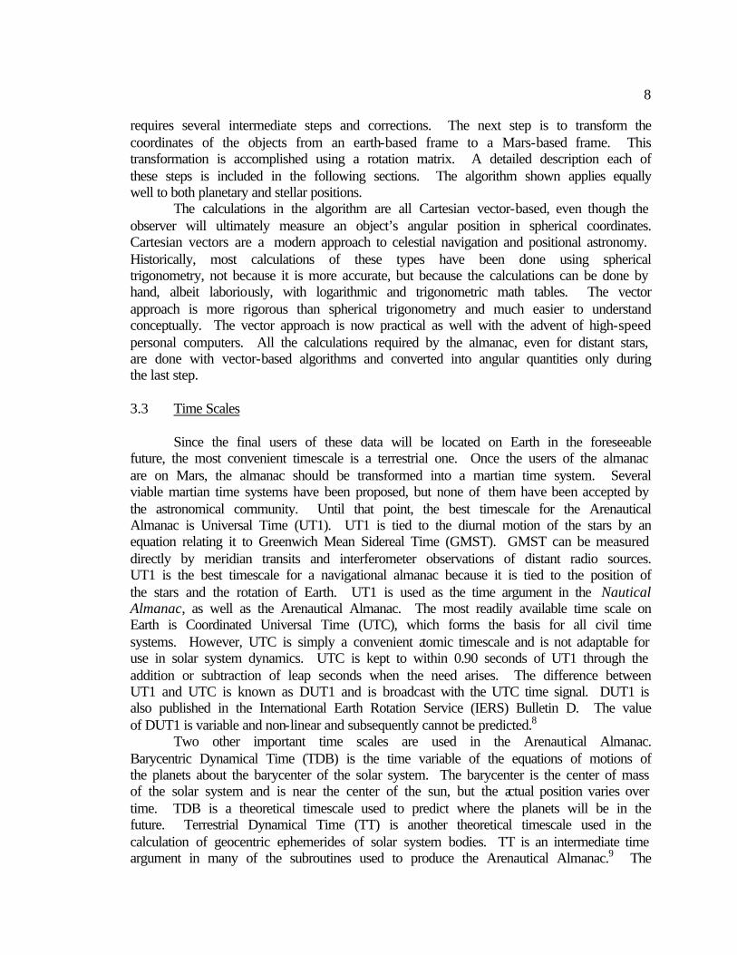
difference between TT and UT1 is known as ∆T, and its value is required to transform between the TT and UT1 timescales. The value of ∆T is variable and can only be predicted accurately approximately one year ahead of time. The predictions of ∆T for 2001 are listed in Table 1, and a fourth order polynomial equation was fitted to these points for interpolating ∆T at any time during 2001, as shown in Figure 3.10
Table 1. Predictions of ∆T for 2001
TT-UT1
y = 1.48053x4 - 8.58880x3 + 18.19387x2 - 16.47880x + 69.48400
64.05
64.1
64.15
64.2
64.25
64.3
0.8 0.9 1 1.1 1.2 1.3 1.4 1.5 1.6 1.7 1.8 1.9 2 2.1
Years past 2000 (years)
TT
-UT
1 (
se
co
nd
s)
Figure 3. Interpolation of ∆T for 2001.0-2002.0
3.4 Areocentric Position The original position data of the planets are contained in the DE405 Planetary Ephemeris. The DE405 is a database of the positions and velocities of all the planets in the solar system, referenced to the center of mass of the solar system in Cartesian coordinates using the International Celestial Reference Frame of epoch 2000.0. The
Year TT-UT1 Prediction Error 2001.0 64.0908 0.000 2001.25 64.153 0.006 2001.5 64.21 0.01 2001.75 64.22 0.02 2002.0 64.28 0.02
10
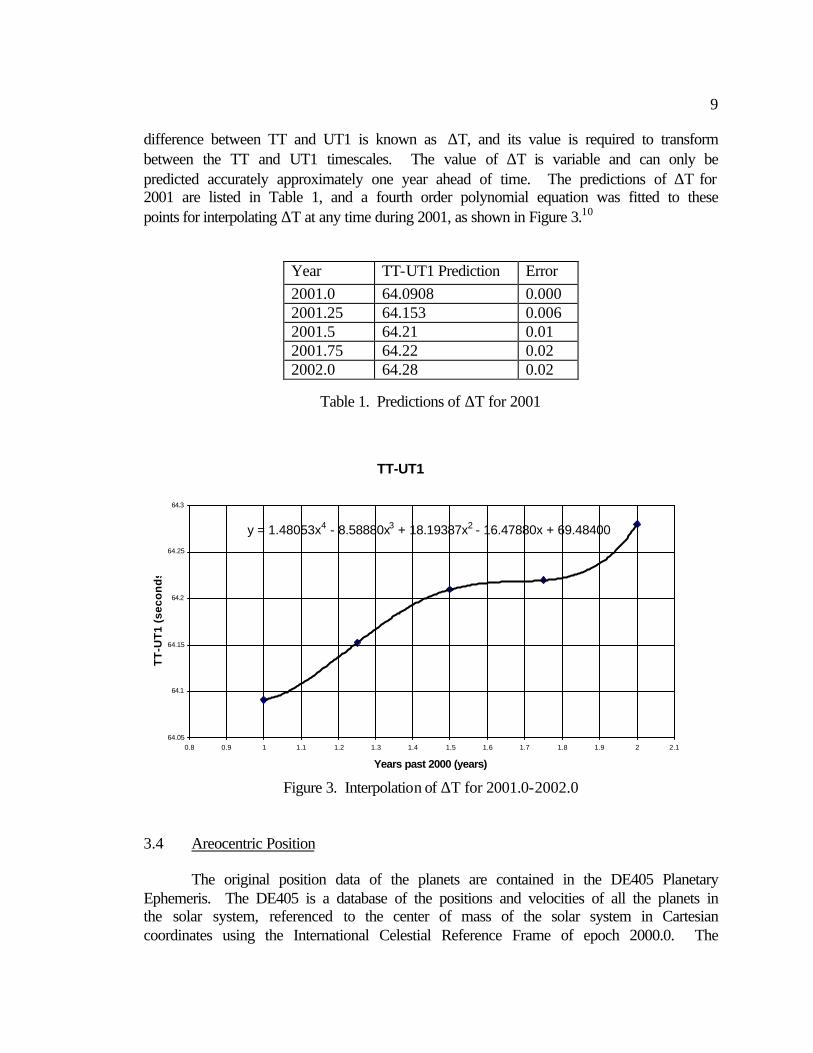
DE405 uses Barycentric Dynamical Time (TDB) scale as the time argument. This ephemeris is computer generated by the Jet Propulsion Laboratory and has better than one arcsecond accuracy for all of the relevant navigable planets. Of all the planets, Mars’ position and velocity are by far the most accurately known.11 The areocentric positions of celestial objects are easily calculated using vector addition, as shown in Figure 4.
Although this new position vector is the exact position of the target planet at the time of observation, it will appear to an observer on Mars to be in a slightly different position due to several effects: light-time correction, aberration, and gravitational light deflection. 3.5 Light-Time Correction It takes a finite amount of time for light to leave the target planet and reach the observer. During that time, the target planet will have moved by a detectable amount, as shown in Figure 5.12
Figure 4. Areocentric Position

11
The light detected by the observer was emitted by the target body at time (t-τ), where τ is the time it takes for light to reach the observer. The observer needs to know where the target body appears to be at time t ( P′(t-τ) ), not where it actually is at time t ( P(t) ). The light-time is calculated using the distance between the two objects, and the observed position is found by entering (t-τ) as the time argument in the ephemeris. 3.6 Aberration Another required correction factor is due to the motion of the observer. The observer is on a planet orbiting at high velocity around the sun, and the position of the target body will move by the amount ∆θ, as shown in Figure 6.13
Figure 6. Aberration
Figure 5. Light-Time Correction
12
Including the effects of special relativity, the angle ∆θ can be calculated from the following equation:
1 1( / ) ( / )( / )/(1 )1 /
c c cc
β β− −+ + ⋅ +=
+ ⋅1
p V p V Vp
p V (1)
where 1 21 ( / )V cβ− = − (2) In Seidelmann (1992), this equation is simplified to:
2 11( / )sin ( / ) /(1 )
2sin1 ( / )cos
V c V c
V c
θ βθ
θ
−+ +∆ =
+ (3)
21
sin sin2 ...4
V Vc c
θ θ = − + (4)
where V is the scalar velocity of the observer’s planet and c is the speed of light. Since the orbital velocity of the planet is very small compared to the speed of light, only the first term in the series is required to calculate the aberration.14 3.7 Gravitational Light Deflection
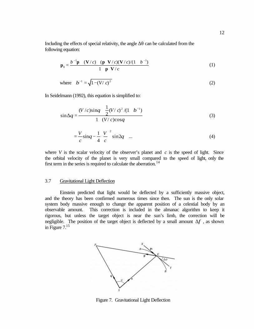
Einstein predicted that light would be deflected by a sufficiently massive object, and the theory has been confirmed numerous times since then. The sun is the only solar system body massive enough to change the apparent position of a celestial body by an observable amount. This correction is included in the almanac algorithm to keep it rigorous, but unless the target object is near the sun’s limb, the correction will be negligible. The position of the target object is deflected by a small amount ∆φ , as shown in Figure 7.15
Figure 7. Gravitational Light Deflection

13
General relativity states that:
2
2 sin1 cosc E
µ ψφψ
∆ =+
(5)
where E is the distance from the observer’s planet to the sun, µ is the sun’s gravitational constant, and c is the speed of light. The apparent position of the target planet is p1 and can be calculated by:
( )sin
φψ
× ×= + ∆1
q e pp p (6)
3.8 Coordinate Frames The almanac algorithm is not coordinate system specific, but it is convenient to use certain coordinate systems at various stages of the calculations. Coordinate frames are defined by four characteristics: a reference body, a reference plane, a reference direction, and a reference time. The reference body can be any planet in the solar system and only helps to identify the coordinate system. An earth-centered coordinate frame can be translated to Mars and still remain accurate. The reference plane is generally the equatorial plane of a planet, but it can be an orbital plane as well. Planes are defined by their normal vector, and in most cases, the normal vector is aligned with the rotational axis of the planet. The reference direction is arbitrary, but several vectors in the reference plane are well defined. Convenient reference directions include the nodes of an orbit or the intersection of two reference planes.
In addition, all objects are moving with respect to the coordinate system, but the coordinate system is moving through space as well. Two reference times must be specified when describing the position of an object: the time at which the object had the particular spatial coordinates and the reference time when the coordinate frame is defined.16 No coordinate system is truly inertial, but a coordinate system defined at a certain reference time has an exact definition that does not change. Coordinate systems based on a reference time in the past are referred to as “of epoch.” Coordinate systems that are based upon the present time are referred to as “of date.”
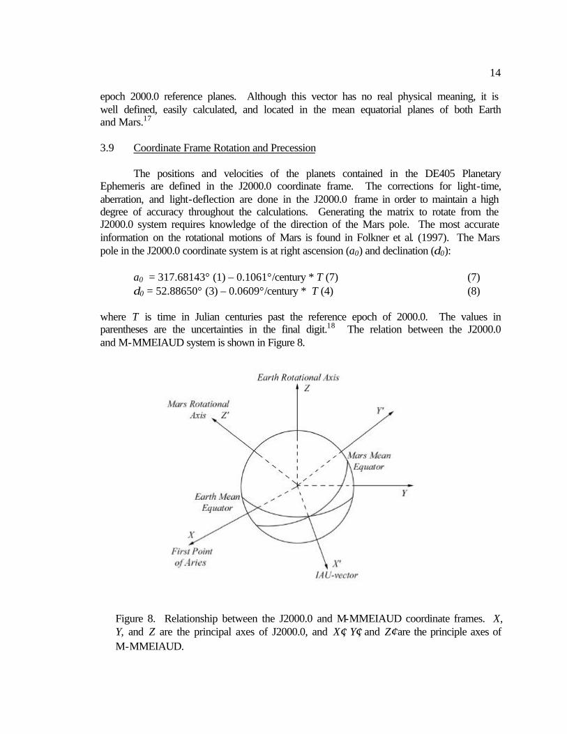
The first important coordinate-frame used in the almanac algorithm is known as the J2000.0 system. It is a terrestrial coordinate-frame defined by the earth’s mean equator with the north pole as the z-axis, the direction to the first point of Aries or vernal equinox as the x-axis, and a reference time of January 1, 2000 12:00:00 UT. The other important coordinate-frame used in the algorithm is the Mars-centered Mars Mean Equator and International Astronomical Union (IAU)-vector of Date, which is abbreviated M-MMEIAUD. This frame uses the rotational axis of Mars as the z-axis, making the equatorial plane the reference plane. The IAU-vector, the x-axis, is a vector along the intersection of the Mars Mean Equator of Date and the Earth Mean Equator of
14
epoch 2000.0 reference planes. Although this vector has no real physical meaning, it is well defined, easily calculated, and located in the mean equatorial planes of both Earth and Mars.17
3.9 Coordinate Frame Rotation and Precession The positions and velocities of the planets contained in the DE405 Planetary Ephemeris are defined in the J2000.0 coordinate frame. The corrections for light-time, aberration, and light-deflection are done in the J2000.0 frame in order to maintain a high degree of accuracy throughout the calculations. Generating the matrix to rotate from the J2000.0 system requires knowledge of the direction of the Mars pole. The most accurate information on the rotational motions of Mars is found in Folkner et al. (1997). The Mars pole in the J2000.0 coordinate system is at right ascension (a0) and declination (δ0):
a0 = 317.68143° (1) – 0.1061°/century * T (7) (7) δ0 = 52.88650° (3) – 0.0609°/century * T (4) (8)
where T is time in Julian centuries past the reference epoch of 2000.0. The values in parentheses are the uncertainties in the final digit.18 The relation between the J2000.0 and M-MMEIAUD system is shown in Figure 8.
Figure 8. Relationship between the J2000.0 and M-MMEIAUD coordinate frames. X, Y, and Z are the principal axes of J2000.0, and X′, Y′, and Z′ are the principle axes of M-MMEIAUD.
15
The time argument in the direction of the Mars pole is due to an effect known as precession. Precession is a very long period motion of the direction of the pole due to the torque of the sun and other planets on Mars’ slightly non-spherical shape. The precession will cause a change in the position of a celestial object as viewed from the planet and can be corrected for with a precession rotation matrix. However, the rate of precession is so slow that its effects can be included in the coordinate-frame rotation.
After the corrections are applied to the original position vector of the target object, the vector must be rotated from the J2000.0 frame to the M-MMEIAUD frame. The first rotation is about the Earth’s z-axis in order to align the direction of the Earth’s vernal equinox with the IAU-vector. This angle is equal to a0 + 90°. The next rotation is about the new x-axis in order to align Earth’s pole with Mars’ pole. This angle is equal as 90°- δ0. The equation for rotating a the coordinate frame from J2000.0 to M-MMEIAUD is as follows:
PM-MMEIAUD = R1(90°- δ0 ) R3(a0 + 90°) PJ2000.0 (9)
where
1 0 0
( ) 0 cos sin
0 sin cos
θ θ θθ θ
=
−
R1 and
cos sin 0
( ) sin cos 0
0 0 1
φ φφ φ φ
= −
R3 (10), (11)
3.10 Nutation
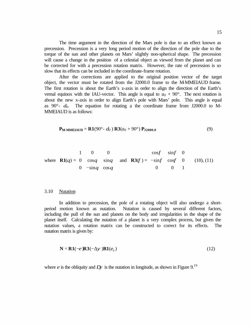
In addition to precession, the pole of a rotating object will also undergo a short-period motion known as nutation. Nutation is caused by several different factors, including the pull of the sun and planets on the body and irregularities in the shape of the planet itself. Calculating the nutation of a planet is a very complex process, but given the nutation values, a rotation matrix can be constructed to correct for its effects. The nutation matrix is given by:
0( ) ( ) ( )ε ψ ε= − −∆N R1 R3 R1 (12) where ε is the obliquity and ∆ψ is the nutation in longitude, as shown in Figure 9.19

16
The effects of nutation are easier to see visually than to explain with mathematical formulas. The following figures compare the nutations of Earth and Mars.20
Figures 10 and 11 depict the motion of each planet’s true pole about the mean pole. The most noticeable difference between the nutation of Earth and Mars is the shape of the pole’s motion. This is because nutation is the combined effect of several different factors. The magnitude of each factor varies for each planet (the Earth’s moon is much bigger than Mars’ moons for example), which shapes the nutation curve differently. Another major difference between Earth and Mars is the magnitude of nutation. The Earth’s true pole moves between -18 and +18 arcseconds in latitude, while Mars’ true pole only moves between –0.5 and +0.6 arcseconds in longitude away from the mean pole. This deviation from the Mars mean pole is very small and within the one arcsecond accuracy required by the almanac. Due to the complexities of calculating nutation, it is reasonable to ignore its effects in the Arenautical Almanac. The concept of nutation is important, however, and should not be ignored until the effects are shown to be negligible.21
Figure 10. Earth Nutation, 18 year period
Figure 11. Mars Nutation, 1 Martian sidereal year (686.93 days)
Figure 9. Nutation
17
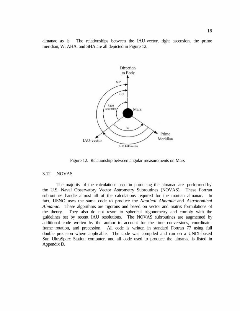
3.13 Spherical Coordinate Systems
The last step in the algorithm is to convert the M-MMEIAUD position vector from Cartesian coordinates to spherical coordinates. This transformation is required to reduce an observation into a celestial line of position. The right ascension of an object is the angle between the IAU-vector and the object, which is positive in an easterly direction. It is defined by:
a = atan2(y,x) (13) where the function atan2 calculates the angle between the positive x-axis and vector (x,y) from 0° to 360°. The declination of an object is the angle between the equatorial reference plane and object’s position vector, from -90° to +90°. It is defined by:
(( ))2 2atan2 ,z x yδδ = += + (14)
An additional coordinate system is needed to relate the M-MMEIAUD system to
the surface of Mars. The prime meridian of Mars is defined by the great circle perpendicular to the Mars mean equator that runs through the center of crater Airy-0. The angle between the IAU-vector and the prime meridian is known as W, which is defined as:
W = 176.901° (fixed) + 350.89198226°/day (8) * T (15)
where the number in parentheses is the uncertainty in the final digit and T is time in days past 2000.0.22 The definition of W is linear, which assumes a constant rotation rate of Mars. The martian day is 24 hours, 37 minutes, and 22.66376 seconds long, which is close to Earth’s day only by coincidence. The last step is to convert the angular position of the target body from right ascension and declination to a coordinate system that can be used directly in a sight reduction. The position of the body must be in angular coordinates that can be added and subtracted to latitude and longitude. On Earth, the quantity used instead of right ascension is the Greenwich Hourly Angle (GHA), the angle between the prime meridian and the target body. GHA is also equivalent to longitude on the surface of a planet. The martian equivalent of GHA is best called the Airy Hour Angle (AHA), the angle between the prime meridian of Mars and the target body. AHA is positive in the westerly direction. The AHA is tied to the rotation rate of Mars, so it changes relatively quickly at a rate of approximately 14.6°/hour. The navigational stars are nearly fixed in position and are located by the Sidereal Hour Angle (SHA), the angle between the IAU-vector and star. The AHA of a star is simply the AHA of the IAU-vector, which is equal to W, plus the SHA of the star, both of which are listed in the almanac. The declination of the object, the equivalent of latitude, does not need any modification and is listed in the
18
almanac as is. The relationships between the IAU-vector, right ascension, the prime meridian, W, AHA, and SHA are all depicted in Figure 12.
3.12 NOVAS The majority of the calculations used in producing the almanac are performed by the U.S. Naval Observatory Vector Astrometry Subroutines (NOVAS). These Fortran subroutines handle almost all of the calculations required for the martian almanac. In fact, USNO uses the same code to produce the Nautical Almanac and Astronomical Almanac. These algorithms are rigorous and based on vector and matrix formulations of the theory. They also do not resort to spherical trigonometry and comply with the guidelines set by recent IAU resolutions. The NOVAS subroutines are augmented by additional code written by the author to account for the time conversions, coordinate-frame rotation, and precession. All code is written in standard Fortran 77 using full double precision where applicable. The code was compiled and run on a UNIX-based Sun UltraSparc Station computer, and all code used to produce the almanac is listed in Appendix D.
Figure 12. Relationship between angular measurements on Mars

19
4.0 Results 4.1 Arenautical Almanac
Two programs were written in order to produce the Arenautical Almanac. Program “marsplan.f” calculates the positions of any planet over a twenty-four hour period, starting at 0 hr UT1. The user specifies the day and month of 2001 and the target body identification number as listed in the NOVAS user guide. The program calculates the observed position of the target object and the displays the position in terms of Airy Hour Angle and declination. The program also displays the Airy Hour Angle of the IAU-vector. A sample output of “marsplan.f” is shown below.
Month: 5 Day: 25 Year: 2001 Target Number: 3 AHA IAU AHA Dec UT1 Deg Min Sec Deg Min Sec Deg Min Sec 0 36 37 36 350 22 37 0 -25 0 1 51 14 50 5 0 9 0 -24 -41 2 65 52 4 19 37 41 0 -24 -21 3 80 29 17 34 15 14 0 -24 -1 4 95 6 31 48 52 46 0 -23 -41 5 109 43 45 63 30 18 0 -23 -21 6 124 20 59 78 7 51 0 -23 -1 7 138 58 13 92 45 23 0 -22 -41 8 153 35 26 107 22 56 0 -22 -22 9 168 12 40 122 0 28 0 -22 -2 10 182 49 54 136 38 1 0 -21 -41 11 197 27 8 151 15 34 0 -21 -21 12 212 4 22 165 53 7 0 -21 -1 13 226 41 35 180 30 39 0 -20 -41 14 241 18 49 195 8 12 0 -20 -21 15 255 56 3 209 45 45 0 -20 -1 16 270 33 17 224 23 19 0 -19 -40 17 285 10 31 239 0 52 0 -19 -20 18 299 47 44 253 38 25 0 -18 -60 19 314 24 58 268 15 58 0 -18 -39 20 329 2 12 282 53 31 0 -18 -19 21 343 39 26 297 31 5 0 -17 -59 22 358 16 40 312 8 38 0 -17 -38 23 12 53 53 326 46 12 0 -17 -18
Table 2. Arenautical Almanac Output of Earth, “marsplan.f”
A second program, “marsstar.f,” performs the same calculations for the fifty-seven brightest navigational stars listed in Nautical Almanac. The algorithm can be modified to work with any star database such as the Tycho-2 or Hipparchos catalogues. The inputs of the program is the day and month of 2001, and the program returns the Sidereal Hour Angle and declination of the navigational stars at 0 hr on the desired day. The number refers to each navigational star’s identification number. The stars have nearly fixed positions in the M-MMEIAUD coordinate frame since they are so distant. However, the program still corrects for gravitational light deflection, aberration,
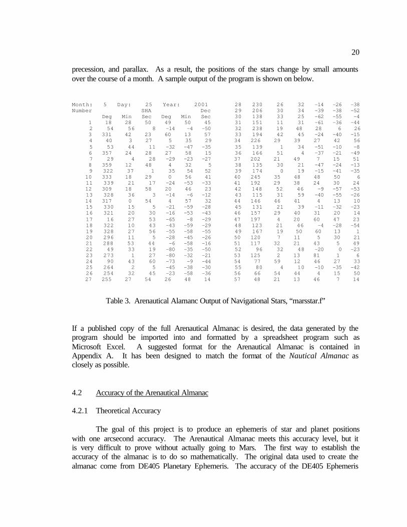
20
precession, and parallax. As a result, the positions of the stars change by small amounts over the course of a month. A sample output of the program is shown on below. Month: 5 Day: 25 Year: 2001 Number SHA Dec Deg Min Sec Deg Min Sec 1 18 28 50 49 50 45 2 54 56 8 -14 -4 -50 3 331 42 23 60 13 57 4 40 3 27 5 35 29 5 53 44 11 -32 -47 -35 6 357 24 28 27 58 15 7 29 4 28 -29 -23 -27 8 359 12 48 4 32 5 9 322 37 1 35 54 52 10 333 18 29 0 56 41 11 339 21 17 -24 -53 -33 12 309 18 58 20 46 23 13 328 36 3 -14 -6 -12 14 317 0 54 4 57 32 15 330 15 5 -21 -59 -28 16 321 20 30 -16 -53 -43 17 16 27 53 -65 -8 -29 18 322 10 43 -43 -59 -29 19 328 27 56 -55 -58 -55 20 296 11 5 -28 -45 -26 21 288 53 44 -6 -58 -16 22 49 33 19 -80 -35 -50 23 273 1 27 -80 -32 -21 24 90 43 60 -73 -9 -44 25 264 2 5 -45 -38 -30 26 254 32 45 -23 -58 -36 27 255 27 54 26 48 14
28 230 26 32 -14 -26 -38 29 206 30 34 -39 -38 -52 30 138 33 25 -62 -55 -4 31 151 11 31 -61 -36 -44 32 238 19 48 28 6 26 33 194 42 45 -24 -40 -15 34 226 29 39 27 42 56 35 139 1 34 -51 -10 -8 36 166 51 4 -37 -21 -49 37 202 21 49 7 15 51 38 135 30 21 -47 -24 -13 39 174 0 19 -15 -41 -35 40 245 35 48 48 50 6 41 192 29 38 24 30 24 42 148 52 46 -9 -57 -53 43 115 31 59 -40 -55 -26 44 146 46 41 4 13 10 45 131 21 39 -11 -32 -23 46 157 29 40 31 20 14 47 197 4 20 60 47 23 48 123 21 46 -4 -28 -54 49 167 19 50 60 13 1 50 120 7 11 5 30 21 51 117 32 21 43 5 49 52 96 32 48 -20 0 -23 53 125 2 13 81 1 6 54 77 59 12 46 27 33 55 80 4 10 -10 -35 -42 56 66 54 44 4 15 50 57 48 21 13 46 7 14
Table 3. Arenautical Alamanc Output of Navigational Stars, “marsstar.f”
If a published copy of the full Arenautical Almanac is desired, the data generated by the program should be imported into and formatted by a spreadsheet program such as Microsoft Excel. A suggested format for the Arenautical Almanac is contained in Appendix A. It has been designed to match the format of the Nautical Almanac as closely as possible. 4.2 Accuracy of the Arenautical Almanac 4.2.1 Theoretical Accuracy The goal of this project is to produce an ephemeris of star and planet positions with one arcsecond accuracy. The Arenautical Almanac meets this accuracy level, but it is very difficult to prove without actually going to Mars. The first way to establish the accuracy of the almanac is to do so mathematically. The original data used to create the almanac come from DE405 Planetary Ephemeris. The accuracy of the DE405 Ephemeris
21
is better than one arcsecond, and Mars’ position by the far most accurately known according to Giorgini et al. (1996). The error in position is assumed to be zero at the start of the algorithm. No error is introduced through the vector addition to get the areocentric position. The corrections for light time, gravitational deflection, and aberration are all performed with NOVAS subroutines. The NOVAS subroutines perform all calculations accurate to the milliarcsecond level.23 The introduced error is so small, it is assumed to be zero as well.
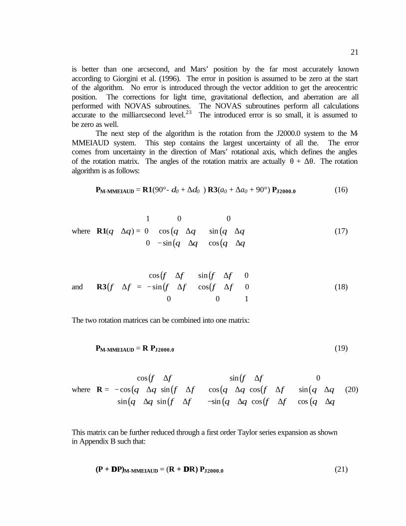
The next step of the algorithm is the rotation from the J2000.0 system to the M-MMEIAUD system. This step contains the largest uncertainty of all the. The error comes from uncertainty in the direction of Mars’ rotational axis, which defines the angles of the rotation matrix. The angles of the rotation matrix are actually θ + ∆θ. The rotation algorithm is as follows:
PM-MMEIAUD = R1(90°- δ0 + ∆δ0 ) R3(a0 + ∆a0 + 90°) PJ2000.0 (16)
where ( ) ( )( ) ( )
1 0 0
( ) 0 cos sin
0 sin cos
θ θ θ θ θ θθ θ θ θ
+ ∆ = + ∆ + ∆ − + ∆ + ∆
R1 (17)
and ( )( ) ( )( ) ( )
cos sin 0sin cos 0
0 0 1
φ φ φ φφ φ φ φ φ φ
+ ∆ + ∆ + ∆ = − + ∆ + ∆
R3 (18)
The two rotation matrices can be combined into one matrix: PM-MMEIAUD = R PJ2000.0 (19)
where ( ) ( )
( ) ( ) ( ) ( ) ( )( ) ( ) ( ) ( ) ( )
cos sin 0cos sin cos cos sin
sin sin sin cos cos
φ φ φ φθ θ φ φ θ θ φ φ θ θ
θ θ φ φ θ θ φ φ θ θ
+ ∆ + ∆ = − + ∆ + ∆ + ∆ + ∆ + ∆ + ∆ + ∆ − + ∆ + ∆ + ∆
R (20)
This matrix can be further reduced through a first order Taylor series expansion as shown in Appendix B such that: (P + ∆∆ P)M-MMEIAUD = (R + ∆∆ R) PJ2000.0 (21)
22
where ( ) ( )
( ) ( ) ( ) ( ) ( )( ) ( ) ( ) ( ) ( )
cos sin 0cos sin cos cos sin
sin sin sin cos cos
φ φθ φ θ φ θ
θ φ θ φ θ
= − −
R (22)
and ( )( )
0φ φθ φ θ φ θ
θ φ θ φ θ
∆ ∆ ≤ − ∆ + ∆ ∆ + ∆ ∆ ∆ + ∆ − ∆ + ∆ ∆
ÄR (23)
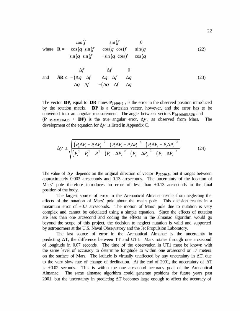
The vector ∆∆ P, equal to ∆∆ R times PJ2000.0 , is the error in the observed position introduced by the rotation matrix. ∆∆ P is a Cartesian vector, however, and the error has to be converted into an angular measurement. The angle between vectors P M-MMEIAUD and (P M-MMEIAUD + ∆∆ P) is the true angular error, ∆ψ, as observed from Mars. The development of the equation for ∆ψ is listed in Appendix C.
( ) ( ) ( )( ) ( ) ( ) ( )
2 22
22 22 2 2
y z z y z x x z x y y x
x y z x x y y z z
P P P P P P P P P P P P
P P P P P P P P Pψ
∆ − ∆ + ∆ − ∆ + ∆ − ∆∆ ≤
+ + + ∆ + + ∆ + + ∆
(24)
The value of ∆ψ depends on the original direction of vector PJ2000.0, but it ranges between approximately 0.003 arcseconds and 0.13 arcseconds. The uncertainty of the location of Mars’ pole therefore introduces an error of less than ±0.13 arcseconds in the final position of the body. The largest source of error in the Arenautical Almanac results from neglecting the effects of the nutation of Mars’ pole about the mean pole. This decision results in a maximum error of ±0.7 arcseconds. The motion of Mars’ pole due to nutation is very complex and cannot be calculated using a simple equation. Since the effects of nutation are less than one arcsecond and coding the effects in the almanac algorithm would go beyond the scope of this project, the decision to neglect nutation is valid and supported by astronomers at the U.S. Naval Observatory and the Jet Propulsion Laboratory. The last source of error in the Arenautical Almanac is the uncertainty in predicting ∆T, the difference between TT and UT1. Mars rotates through one arcsecond of longitude in 0.07 seconds. The time of the observation in UT1 must be known with the same level of accuracy to determine longitude to within one arcsecond or 17 meters on the surface of Mars. The latitude is virtually unaffected by any uncertainty in ∆T, due to the very slow rate of change of declination. At the end of 2001, the uncertainty of ∆T is ±0.02 seconds. This is within the one arcsecond accuracy goal of the Arenautical Almanac. The same almanac algorithm could generate positions for future years past 2001, but the uncertainty in predicting ∆T becomes large enough to affect the accuracy of
23
the final almanac. The almanac could be propagated further by using a theoretical time scale such as TT as the time argument, but it was desired to keep the format of the Arenautical Almanac as close to the Nautical Almanac as possible. 4.2.2 Comparison with Ephemeris for Physical Observations
One of the only methods to check the accuracy of the Arenautical Almanac with an outside source is to compare the predicted position of Earth from Mars with data contained in a section of the Astronomical Almanac called “Mars, Ephemeris for Physical Observations.” The Ephemeris for Physical Observations is not precise enough to measure the full accuracy of the Arenautical Almanac, but it makes a very useful “sanity check” to see if the almanac algorithm has any major errors. This table lists the latitude and longitude of the subearth point and the subsolar point at 0 hr TT on a given day accurate to one hundredth of a degree. The information is produced by the U.S. Naval Observatory using many of the same NOVAS subroutines as the Arenautical Almanac.
The subearth point is the point where a line connecting the center of Earth and the center of Mars would intersect the surface of Mars, as seen at time t by an observer on Earth. Similarly, the subsolar point is the point where a line connecting the center of the sun and the center of Mars would intersect the surface of Mars as seen at time t by an observer on Earth. The Earth should be directly overhead for an observer on Mars at time t + τ, where τ is the light-time between Earth and Mars at time t. The same is true of the sun for an observer standing at the subsolar point. The latitude and longitude listed in the Ephemeris for Physical Observations are in planetographic coordinates, rather than planetocentric coordinates. Planetographic coordinates take into account the non-spherical shape of the planet. Planetographic longitude, λ′, is measured positively in the direction opposite to the rotation of the planet, which is the same angular measurement as the AHA of an object. Planetocentric latitude, φ, is the same angle as declination but can be converted into planetographic latitude, φ′, by the following equation:
( )1
2
tantan
1'
f
φφ −
= −
where ( )a b
fa−
= (25), (26)
and a is the equatorial radius of the planet, and b is the polar radius of the planet.24 At time t + τ, the position of the Earth and Sun as tabulated in the Arenautical Almanac and converted into planetographic coordinates should be equal to the positions of the subearth and subsolar at time t. The position of Earth as seen from Mars was calculated with the Arenautical Almanac at 0 hr TT plus τ on several days in 2001. The positions were then converted from AHA and declination to planetographic longitude and latitude and compared with the latitude and longitude of the subearth point on Mars at 0 hr TT. The difference between the two should theoretically be zero. These values are listed in Table 4.

24
λ′ φ′ λ′ φ′ λ′ φ′ λ′ φ′
Arenautical Almanac 249.23 18.17 185.92 9.03 127.63 0.74 331.11 -0.15Ephemeris for Physical Observations 249.26 18.17 185.95 9.03 127.66 0.74 331.15 -0.14
Delta 0.03 0.00 0.03 0.00 0.03 0.00 0.04 0.01
λ′ φ′ λ′ φ′ λ′ φ′ λ′ φ′
Arenautical Almanac 11.65 6.21 24.35 -1.99 239.64 -16.63 86.09 -25.95Ephemeris for Physical Observations 11.69 6.21 24.38 -1.99 239.67 -16.63 86.12 -25.95
Delta 0.04 0.00 0.03 0.00 0.03 0.00 0.03 0.00
All values in degrees
27-May-01
02-Jul-01 16-Sep-01 07-Nov-01 29-Dec-01
All values in degrees
03-Jan-01 16-Feb-01 01-Apr-01
The values of ∆φ′ are zero for almost every date except for 27 May 2001. This one discrepancy is due to rounding in the Arenautical Almanac calculations. The ∆λ′ is 0.03° for almost every date, which would be a sizable error if real. However, after discussion with Mr. John Bangert at the U.S. Naval Observatory, it was decided that the offset is most likely a rounding error in the Ephemeris for Physical Observations, due to that table’s lower precision. The Ephemeris for Physical Observations only tabulates the values of the subearth and subsolar point to the hundredth of a degree, and the 0.03° offset is within the uncertainty of the calculations. Again, it should be stated that due to the lower number of significant digits in the Ephemeris for Physical Observations, the comparison with Arenautical Almanac data is not much more than a sanity check. It is useful for finding major errors in the theory, algorithm, and computer code. Since the deltas in latitude and longitude are so small, the Arenautical Almanac passes this test. 4.3 Overall Accuracy Assessment
The Arenautical Almanac does in fact meet the one arcsecond accuracy goal set in the beginning of the project. The NOVAS algorithms themselves do not introduce any measurable error into the final position of a celestial body on Mars. The uncertainty of the position of Mars’ pole introduces an error less than ±0.13 arcseconds. By neglecting
Table 4. Comparison between Arenautical Almanac and Ephemeris for Physical Observations
25
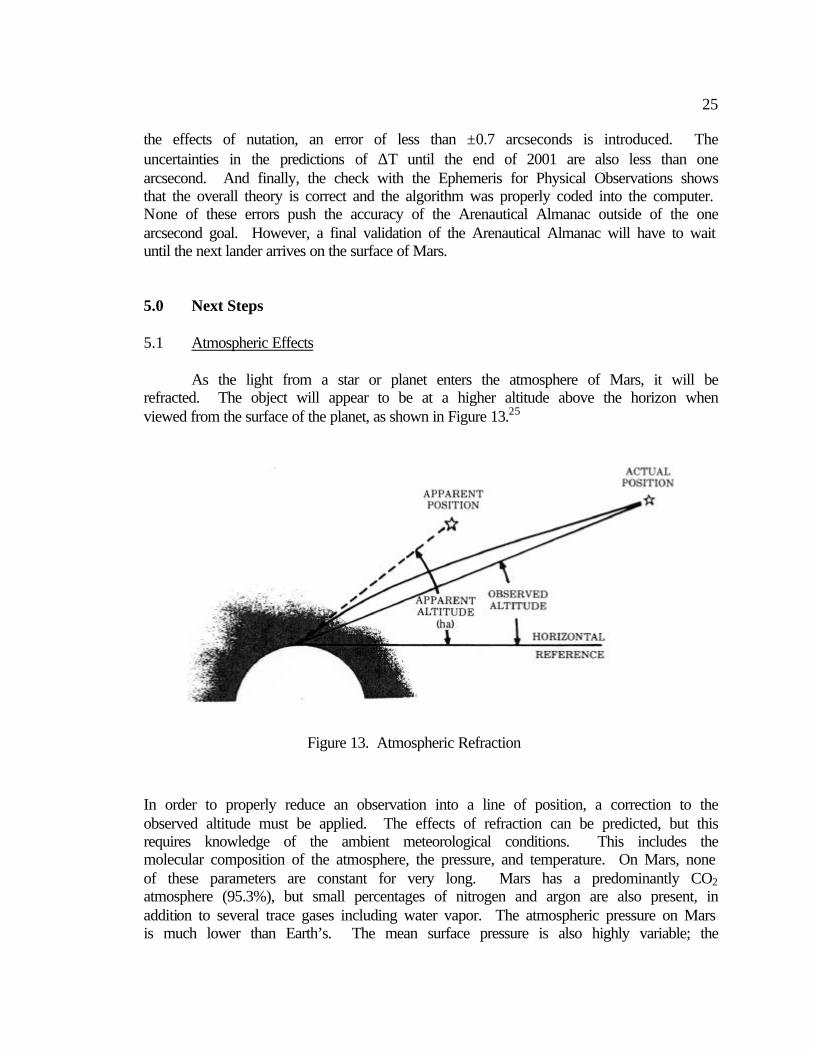
the effects of nutation, an error of less than ±0.7 arcseconds is introduced. The uncertainties in the predictions of ∆T until the end of 2001 are also less than one arcsecond. And finally, the check with the Ephemeris for Physical Observations shows that the overall theory is correct and the algorithm was properly coded into the computer. None of these errors push the accuracy of the Arenautical Almanac outside of the one arcsecond goal. However, a final validation of the Arenautical Almanac will have to wait until the next lander arrives on the surface of Mars. 5.0 Next Steps 5.1 Atmospheric Effects As the light from a star or planet enters the atmosphere of Mars, it will be refracted. The object will appear to be at a higher altitude above the horizon when viewed from the surface of the planet, as shown in Figure 13.25
In order to properly reduce an observation into a line of position, a correction to the observed altitude must be applied. The effects of refraction can be predicted, but this requires knowledge of the ambient meteorological conditions. This includes the molecular composition of the atmosphere, the pressure, and temperature. On Mars, none of these parameters are constant for very long. Mars has a predominantly CO2 atmosphere (95.3%), but small percentages of nitrogen and argon are also present, in addition to several trace gases including water vapor. The atmospheric pressure on Mars is much lower than Earth’s. The mean surface pressure is also highly variable; the
Figure 13. Atmospheric Refraction
26
Viking 1 lander measured pressures between 6 millibars and 9 millibars in comparison to Earth’s relatively constant 1000 millibars. The diurnal temperature variation is also very large, ranging from approximately 180 K to 240 K. The complications get worse near the colder poles where large amounts of carbon dioxide and water freeze out of the atmosphere and onto the surface, resulting in even lower pressures. However, if the ambient meteorological conditions can be measured or predicted at the time of observation, the atmospheric refraction can be corrected for.26 Despite these challenges, atmospheric refraction poses less of a problem for celestial navigation on Mars than it does on Earth. The pressure on the surface Mars is not even a hundredth of that on Earth on the surface, and pressure decreases exponentially with altitude. The correction for atmospheric refraction also decreases with altitude above the horizon, because the light rays travel through less air. The observer can decide to only take measurements of celestial objects above a certain altitude where atmospheric refraction is negligible. A survey into the astronomy literature also reveals several studies on the atmospheric refraction of Mars. Many of the reports are published in Russian, but some of the research and data could be used to produce an accurate correction table suitable for celestial navigation. Another issue that may be as problematic as atmospheric refraction is the prevalence of very fine dust in the martian atmosphere. The dust particles, composed mostly of iron oxides, will scatter light as it travels through the atmosphere. This effect will dim celestial objects, but might also change their observed position unpredictably. This issue certainly warrants further investigation. 5.2 Preliminary Design of an Autonomous Celestial Navigation System on Mars
Celestial navigation on the surface of Mars would not be possible without the Arenautical Almanac, but the almanac alone does not make a navigation system. This section outlines the components of an autonomous system and discusses some of the design considerations and challenges.
Celestial navigation requires measuring the altitudes of celestial bodies and reducing those observations into celestial lines of position. On the Earth, the altitude is measured from the visible horizon, which, for a ship on the ocean, is an easily observed and near inertial reference plane. An observer on the surface of Mars does not have a flat horizon because of hills, craters, rocks, and other features. However, there are substitutes for the visible horizon. Gravity will pull an object straight down, and if the direction of the local gravity vector can be measured, it would make an excellent reference direction. The altitude of a celestial body would be ninety degrees minus the angle between the body and the local vertical, which could be found with a vector dot product. Electronic instruments capable of measuring the direction of the local vertical are commonly used in cartography equipment, gravity meters, and sight levels. The accuracy of these instruments is quite amazing considering their small size, and one arcsecond is certainly attainable.
However, these instruments are extremely sensitive to external accelerations since the acceleration due to gravity is indistinguishable from any other acceleration. That means that these instruments can only be used on non-moving objects, such as an
27
immobile lander or a temporarily stopped rover. This requirement does not pose much of an operational problem, because a rover will have to stop periodically during the day to take measurements and will not travel at night due to the limited amounts of power available. These gravity-sensing instruments are well suited for use on a spacecraft since they require small mass, volume, and power budgets. If the requirement that the lander remains stationary is too much of an operational burden, an inertial navigation system (INS) could be used to provide the direction of the local vertical even while the lander is moving. This advantage comes at a higher cost, mass, and complexity. However, INS would complement a celestial navigation system very well. The INS would provide the direction of the local vertical to the celestial navigation system and keep track of where the rover is between celestial fixes. The celestial navigation system, meanwhile, would provide external updates to the INS to correct for gyroscopic drift.
The next required instrument is a sextant to measure the altitude of a celestial body. On Earth, the most common instrument is an optical sextant, but they are manually operated and have limited accuracy. The best instrument to measure the position of the stars and planets is a charged coupled device (CCD). These electronic cameras are used in star trackers that determine spacecraft attitude by measuring the positions of stars in relation to the spacecraft. They could be modified to measure the position of the stars and planets in relation to the local vertical, which is in fact a simpler problem than attitude control. Most star trackers have subarcsecond accuracy, are space qualified, and could easily be modified to work on Mars. An issue that still needs analysis is determining which frequencies of light are most easily observed through the martian atmosphere. Certain colors will be absorbed by the atmosphere and will not be observable from the surface. There may also be certain frequencies that can be seen during the daylight, allowing a celestial fix to be taken anytime. Another possibility is to use a lander’s regular camera to image celestial bodies. Currently, these instruments have slightly less than one arcsecond accuracy, and it would be difficult to modify the software to take pictures of dim objects such as stars. A star tracker has such high accuracy not because of its optics, but from the image processing software used to measure stellar positions. However, unprocessed images of celestial bodies taken by a lander’s cameras could be sent to Earth for a more thorough analysis than is currently possible autonomously. A fix could be reduced from the images and the updated position could be sent back to the lander on Mars. This is not an ideal system, but it would make a good validation of the Arenautical Almanac and other components of a celestial navigation system.
Another important instrument required for celestial navigation is an accurate clock. The time must be known to within 0.07 seconds of UT1 in order to maintain one arcsecond accuracy, and this is certainly not a difficult requirement. However, time keeping on Mars has its own challenges. First, the spacecraft clock has to be updated with UT1 on a regular basis. The lander’s clock will slowly drift away from UT1 due to clock errors and the effects of relativity. Since Mars has a smaller gravitational field than Earth, a clock on Mars will run at a different rate than it would Earth. This effect can be accounted for either mathematically or could be included in the periodic updates of UT1. If the clock was not sent periodic updates of UT1 from Earth, the uncertainty of the

28
celestial fix in longitude would get larger and larger, but uncertainty in latitude would remain largely unaffected.
The final component of an autonomous celestial navigation system is a computer that controls the other components, stores the Arenautical Almanac, and reduces the observations into a position on the surface. These calculations are not very complicated or time consuming, so the lander’s processor could probably handle the load in addition to fulfilling its other duties. The computer would use a modified version of the STELLA software for the sight reduction. A version of the Arenautical Almanac would be stored on the lander’s hard drive for easy access. The system would also require additional image processing software for the CCD sextant. The sextant will require a star recognition program to determine which bodies are being observed. This type of software already exists for spacecraft attitude control applications, and would only have to be slightly modified for use on Mars.
Overall, an autonomous celestial navigation system is a fairly simple design. None of the required components need to be invented or re-invented. They are all used in various unrelated systems but have not been merged into a celestial navigation system. Such a system could easily be tested and validated on Earth before it is sent to Mars, and there is no reason why it would not work once it gets there. Now that the Arenautical Almanac exists, celestial navigation is possible from the surface of Mars, and hopefully NASA will further develop this tool. 5.3 Integrating Celestial Navigation into NASA’s Mars Exploration Initiative The first step in turning celestial navigation into a viable system of navigation on Mars is to complete the development of atmospheric refraction corrections and conduct an analysis of the effects of atmospheric dust. The next step is validating the Arenautical Almanac on Mars. Images of celestial bodies must be taken by a lander’s camera with an accurate time stamp from a known position on the surface. A celestial fix can then be calculated and compared with the established position. There should not be much discrepancy between the two unless there is an unknown motion or irregularity in Mars’ rotation that remains undiscovered or is larger than predicted. A fix accurate to one arcsecond or seventeen meters may not be possible at first, but a decrease in accuracy of one order of magnitude is still better than any current navigation system. With the Arenautical Almanac validated on Mars, work can begin on the actual autonomous navigation system. Compared with the technical wonders aerospace engineers produce on a regular basis, this job should not be especially difficult. All spacecraft have very tight mass, power, and computation budgets, and any navigation system should not tax other systems unreasonably. Although a martian GPS system is the best solution to navigation in the long run, the development of such a system is difficult and expensive. Similar capabilities can be realized with a lot less money and time, at least in the near future when space exploration budgets are very limited. Even when construction of the martian GPS system begins, it will be several years before the infrastructure is in place. In the meantime, celestial navigation could do the job and would be a valuable backup to GPS once that service becomes available.

29
A bigger challenge is determining how to incorporate celestial navigation into the operations concept of a Mars lander. Currently, rovers on Mars are limited to short traverses across the surface. The Sojourner rover stayed within meters of the Pathfinder lander throughout its entire mission. This limitation was largely imposed by the small size of the rover and the lack of a suitable navigation system. The next generation of rovers set to launch for Mars in 2003 are to travel over one hundred meters a day, but they will use photographs of the landscape and receive detailed commands from Earth to navigate across the surface. The third generation of rovers will be much larger, more capable, and can traverse up to one kilometer each day. An autonomous navigation system would allow for much more flexible surface operations, since a rover would not have to wait for position information and commands from Earth to tell it where to go next.
The same principles that make celestial navigation possible on the surface could also be used to make precision landings from orbit. The only position information a spacecraft receives as it nears atmospheric entry is from the Deep Space Network. The DSN is highly accurate in range information, but not nearly as accurate in azimuth. This results in probable landing areas hundred of kilometers long. NASA would like to land a rover within ten kilometers of an interesting surface feature in the near future, but that capability certainly does not exist today. A celestial navigation system similar to a surface navigation system but with a horizon sensor instead of a local vertical sensor could help make precision landings possible.
Celestial navigation on Mars has many advantages in the near term. It is unfortunate that practically no research has been done on this subject, especially considering this approach’s relative simplicity, low cost, and accuracy. The fact remains that Mars landers will require some sort of navigation system in this decade. Celestial navigation is typically thought of as a relic of yesteryear, but coupled with a modern approach and modern technology, it becomes an excellent solution to a classic problem. Hopefully, this research project is the first step towards realization of celestial navigation on Mars. 6.0 Summary
The purpose of this project was to devise a method of celestial navigation that can fix a position on Mars with 100-meter accuracy. The first and most important step was to create the Arenautical Almanac, a table of stars and planet positions referenced to the center of Mars, accurate to within one arcsecond. This ephemeris was created mathematically utilizing the standard NOVAS subroutines in addition to the author’s own Fortran code. Barycentric position data contained in the DE405 Planetary Ephemeris were converted into areocentric positions and corrected for the effects of light-time, aberration, and gravitational light deflection. The positions were then rotated from the J2000.0 frame into the M-MMEIAUD frame, accounting for precession in the same step. The nutation of Mars was shown to be small enough to neglect. The theoretical accuracy of the almanac algorithm was established mathematically, and the validity of the algorithm and computer code was verified by a comparison with the Ephemeris for
30
Physical Observations. The Arenautical Almanac meets the one arcsecond goal established at the beginning of the project. Finally, a preliminary design of an autonomous celestial navigation system was presented, along with a discussion of how to incorporate this approach into NASA’s Mars exploration initiative. This project is the first step towards establishing celestial navigation as a practical way to find position on the surface of Mars. This solution is available to robotic probes now and to the inevitable human explorers soon to come. 7.0 Acknowledgements This project would not have been possible without the help of several people in particular. I would first like to thank Dr. Richard Fahey for his insight into this project, but also for his guidance and friendship during this tumultuous year. Conversations about Mars quickly changed into discussions about the Academy, graduate school, and life in general. This project would not have been a success without the very generous support of the U.S. Naval Observatory. The Arenautical Almanac grew out of initial brainstorming sessions with Dr. Kenneth Seidelmann and would not have been completed without the technical expertise of Dr. George Kaplan and John Bangert. Mr. Bangert deserves extra thanks for answering all of my many questions and emails over the course of the year. I would also like to thank Joe Guinn of the Jet Propulsion Laboratory for hosting me during a two-week visit to Pasadena last summer. He gave me an insight into NASA’s Mars exploration program I never could have gotten elsewhere, and he pointed me in the right direction at the start of my research. Finally, I would like to thank Dr. Joyce Shade for all the hard work she puts into the Trident program every day. I have really enjoyed my Trident project this year, and I learned more than I ever thought I would.

31
References
1. “Location and Geologic Setting for the Three U.S. Mars Landers.” T.J. Parker, and R.L. Kirk. Jet Propulsion Laboratory, 1998.
2. MacKenzie, Donald. Inventing Accuracy. Cambridge: MIT Press, 1990.
3. NASA Press Release. “NASA OUTLINES MARS EXPLORATION PROGRAM FOR NEXT TWO DECADES.” October 26, 2000.
4. United States. SPAWAR Systems Center and U.S. Naval Observatory. White
Paper-Response to ONR BAA 00-006. 5. Kaplan, G. New Technology for Celestial Navigation. Proceedings, Nautical
Almanac Office Sesquicentennial Symposium: USNO, 1999. 6. Hobbs, Richard R. Marine Navigation. Annapolis: Naval Institute Press, 1998.
297, Figure 16-12B. 7. ibid. 300, Figure 16-13D. 8. Seidelmann, P.K. Explanatory Supplement to the Astronomical Almanac. Mill
Valley: University Science Books, 1992. 48-54. 9. ibid. 41-44. 10. “Long Term Predictions of Delta T.” [ftp://maia.usno.navy.mil/ser7/deltat.preds].
2001. 11. Giorgini, J.D., Yeomans, D.K., Chamberlin, A.B., Chodas, P.W., Jacobson, R.A.,
Keesey, M.S., Lieske, J.H., Ostro, S.J., Standish, E.M., Wimberly, R.N., "JPL's On-Line Solar System Data Service", Bulletin of the American Astronomical Society 28(3), 1158, 1996.
12. Seidelmann, P.K. op. cit. 128, Figure 3.251.1. 13. ibid. 128, Figure 3.252.1. 14. ibid. 129. 15. ibid. 136, Figure 3.26.1. 16. ibid. 9.
32
17. Mase, Robert. Internal Document. “Update to Mars Coordinate Frame
Definitions.” Jet Propulsion Laboratory, 15 July 1999. 18. Folkner, W.M., Yoder, C.F., Yuan, D.N., Standish, E.M., Preston, R.A. “Interior
Structure and Seasonal Mass Redistributon of Mars from Radio Tracking of Mars Pathfinder.” Science 278 (5 December 1997): 1749-1752.
19. Seidelmann, P.K. op.cit. 115, Figure 3.222.1. 20. Hilton, James. “Motion of Mars’ Pole. I. Rigid Body Precession and Nutation.”
Astronomical Journal 102 (October 1991): 1510-1527. 21. ibid. 22. Folkner, W.M., Yoder, C.F., Yuan, D.N., Standish, E.M., Preston, R.A. op. cit.
1749-1752. 21. Kaplan, G. H., Hughes, J. A., Seidelmann, P. K., Smith, C. A., Yallop, B. D.
“Mean and Apparent Place Computations in the New IAU System. III - Apparent, Topocentric, and Astrometric Places of Planets and Stars.” Astronomical Journal 97 (April 1989): 1197-1210.
24. Seidelmann, P.K. op. cit. 387-391. 25. Hobbs, Richard R. op. cit. 347, Figure 19-12. 26. “Mars Fact Sheet.” [http://nssdc.gsfc.nasa.gov/planetary/factsheet/marsfact.html].
2001.