cell organelles at uncoated cryofractured surfaces...
TRANSCRIPT

J. Cell Sci. 21, 47-58 (1976) 4 7
Printed in Great Britain
CELL ORGANELLES AT UNCOATED
CRYOFRACTURED SURFACES AS VIEWED
WITH THE SCANNING ELECTRON
MICROSCOPE
P. S. WOODS AND MYRON C. LEDBETTERBiology Department, Queens College, Flushing, New York 11367, U.S.A. andBiology Department, Brookhaven National Laboratory, Upton, New York 11973,U.S.A.
SUMMARY
A method of direct visualization of cell organelles by scanning electron microscopy (SEM)is described. Plant and animal tissues fixed in glutaraldehyde and osmium tetroxide are treatedwith the ligand thiocarbohydrazide and a second osmium tetroxide solution, to increase theirosmium content. Tissues are then dehydrated, infiltrated with an epoxy monomer, and togethersolidified with dry ice and fractured. The pieces are transferred to pure acetone, critical-pointdried, attached to stubs with silver paint and viewed by SEM. The ligating procedure increasesthe osmium concentration at its original bonding site sufficiently to render the tissue electri-cally conductive, thus obviating the need for metallic coating. The organelles at the fracturedsurface are revealed in relation to their osmium incorporation rather than by surface irregu-larities as with coating methods. The image derived from the uncoated surface approaches inresolution that of transmission electron micrographs of thin sections. A portion of the imagearising from a small distance below the surface, while at progressively lower resolution,provides some 3-dimensional information about cell fine structure.
INTRODUCTION
Observation of plant or animal cell organelles by scanning electron microscopy(SEM) based on surface irregularities has been demonstrated by others using variousmethods (Guttman & Styskal, 1971; Lim, 1971; Panessa & Gennaro, 1972, 1973;Humphreys & Wodzicki, 1972; Tanaka & lino, 1972; Humphreys, Spurlock &Johnson, 1974). In one method, Tanaka & lino (1972) exposed the contents of cellsby cracking frozen, osmium-fixed tissues infiltrated with monomeric epoxy resin.These workers identified some of the organelles by small surface irregularities in theotherwise smooth break after the pieces were dried and coated with a heavy metal.We repeated this method and found by careful stereoscopic observation of pairs ofmicrographs that some of the secondary electron signal was derived from below thecoated surface, presumably from the osmium absorbed by particular structuresduring fixation. We sought ways to enhance that part of the image which comes fromthe osmium-rich organelles, while diminishing that part which shows surface irregu-larities. After several attempts we found a way to view the fractured surface directlywithout coating, thus permitting us to observe the organelles at and just beneath the

48 P. S. Woods and M. C. Ledbctter
surface at relatively high resolution. This was accomplished by using the thiocarbo-
hydrazide (TCH)-osmium ligating method developed by Seligman, Wasserkrug &
Hanker (1966) to stain tissue sections for transmission electron microscopy (TEM),
and later modified by Kelley, Dekker & Bluemink (1973) to render bulk tissues
electrically conductive for surface viewing with the SEM. Using this procedure, it
became apparent that osmium ligation in combination with resin cracking provides
a new way to study cell fine structure with the SEM. We present here a more extensive
account of our preliminary findings reported earlier (Woods & Ledbetter, 1974).
MATERIALS AND METHODS
Preparation of tissues prior to fixation
We explored the usefulness of the method for plants and animals by using corn root tipsand portions of tadpole tail. Corn (Zea mays L.) seeds were germinated in the dark at 18 °Cbetween layers of thick filter paper moistened with distilled water and grown for 8 or 9 daysprior to fixation. Frog (Rana catesbeiana Shaw) tadpoles approximately 6 cm long werecollected in the wild and maintained in the laboratory in 15-I. tanks under conditions similarto those in nature. A relaxed condition of the tail muscle was achieved prior to fixation byforcing the tadpole to succumb to exhaustion. Samples were taken from root tips and smallpieces of tadpole tail (2 mm') containing epidermis and muscle.
Buffers and washes
The buffers for the fixing solutions and washes were 005 M throughout, with Sorenson'sphosphate at pH 6-8 being used for the corn roots and cacodylate at pH 7-4 being used forthe tadpole tails. Washes in buffer were done 3 times at i-h intervals, and washes in waterwere done 4 times at 05-h intervals. Washes after OsO4 and TCH treatment were at 45 CC toensure removal of free reagent and prevent the deposition of TCH crystals in the tissue.
Preparation of the TCH
The often pinkish TCH crystals (05 g in a small beaker) were washed by repeated rinsingwith distilled water until colourless. The washed crystals in 25 ml of water were heated to60 CC for a few minutes, and then cooled to room temperature for 1 h to attain saturation atthat temperature. During preparation the solution was shielded from strong light and beforeuse was filtered by syringe through a Millipore filter of o^y-fim pore size.
Dehydration and infiltration of tissue
Dehydration of samples was done in a graded series of acetone-water mixtures at concen-trations of 10, 30, 50, 70, 90% and pure acetone, all carried out in an ice bath to minimizeosmotic effects, with changes at 05-h intervals. The specimens in pure acetone were warmedto room temperature and 2 more changes of acetone were made to assure dryness. Infiltrationwith epoxy resin monomer (Epon 812) was through a series of 25, 50, and 75% monomer inacetone at 2-h intervals, followed by pure monomer overnight and daily changes of puremonomer for 3 more days using a tissue rotator set at 1 rev/min.
Fracturing, drying and mounting of tissue on stubs
Tissues to be cracked in epoxy monomer were positioned in a shallow well drilled in a 6-mmaluminium plate with about half of the tissue projecting from the well and with a minimum ofresin left in the well. The plate with the tissue was chilled with powdered dry ice to solidify

Cell organelles viewed with SEM 49
the resin with the tissue. To do this it was found convenient to use an ice bucket with a tightlyfitted lid to prevent ice crystals from forming on the tissue. Cracking was accomplished by asingle thrust of a knife precooled with liquid nitrogen. Dry ice may be used to chill the knifeif care is taken to keep the knife thoroughly cooled prior to making the fracture. The plate andall of the cracked pieces of tissue were plunged into acetone at room temperature. The crackedtissues were collected in vials, washed a few times with pure acetone to remove the resin anddried by the critical point method of Anderson (1951) using liquid CO2. Acetone was thetransition fluid (Porter, Kelley & Andrews, 1972). The dried pieces were attached to aluminiumstubs with silver paint and examined uncoated by SEM at from 10 to 30 keV with the fractureface of the specimen oriented nearly normal to the electron beam.
Outline of the procedure
The excised tissues to be prepared for SEM were: (1) fixed in buffered glutaraldehyde(3 %) f°r J h a nd 6 % for 2 h, the latter finally heated to 45 °C for 15 min for more completefixation, cooled to room temperature and washed in buffer; (2) treated in 2% buffered OsO4overnight and washed in water at 45 °C; (3) treated with saturated TCH at room temperaturefor 3 min, heated to 45 °C for 15 min, washed with water at 45 °C and cooled to room tem-perature; (4) treated with 1 % aqueous OsO, for 1 h and rinsed with water; (5) dehydrated incold acetone; (6) infiltrated with epoxy resin monomer; (7) chilled, cracked, and washed inacetone; (8) dried by the critical point method; and (9) mounted on stubs and observed bySEM.
For some specimens steps 3 and 4 were repeated (osmium ligated twice) to increase theosmium content even further.
Procedure for TEM
Samples for TEM were processed through steps 1 through 5 (above), infiltrated in anepoxy mixture based on Luft (1961), polymerized at 60 CC for 3 days, sectioned with a diamondknife, and observed without further staining at 80 keV.
RESULTS
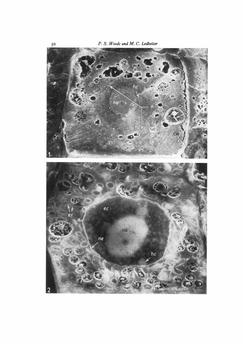
Figs. 1 and 2 compare the results achieved by the two methods of rendering tissueelectrically conductive. In Fig. 1 a xylem initial cell in interphase from a corn roottip was fractured and coated with gold according to the procedures of Tanaka &lino (1972). The limits of the cell are outlined by the wall, which appears bright dueto the roughness of the fracture through the fibrous wall. Conspicuous vacuolesappear within the cytoplasm especially in the upper portion of the figure. A largenucleus is located centrally, with its lighter nucleolus and presumed heterochromatinbodies against the darker nucleoplasm. Presumably most of the secondary electronsdetected here arise from the gold coat applied to reveal the surface and provide aconductive path for electrons; however, stereoscopic study of pairs of such imageslead us to the conclusion that a portion of the signal, notably that from parts of thenucleolus and chromatin, originates from below the coat, probably from the denserconcentrations of osmium present in these regions. The remainder of the cytoplasmshows some irregularities in the fracture plane induced by various organelles asso-ciated with such cells, but interpretation is difficult at best. In contrast, Fig. 2 showsa cell probably in interphase and is from a corn root tip rendered electrically conduc-tive by osmium ligation. The root was fractured in the same manner as that used forthe cell in Fig. 1, but in this case is viewed uncoated. In this method sufficient
P. S. Woods and M. C. Ledbetter

Cell organelles viewed with SEM 51
reduced osmium has accumulated in the specimen to provide a conductive path bywhich excess electrons may pass from the specimen to the grounded stub, thusavoiding charging effects. The image in Fig. 2 is derived almost exclusively fromsecondary electrons with little contribution from primary backscattered electrons asdetermined by the almost undetectable image displayed upon reversal of the + 300 Vfrom the collector screen to —100 V to visualize backscattered electrons. The signalof secondary electrons will vary with the concentration of osmium within the tissue,rather than with surface irregularities, as for a metal-coated specimen. This differencein the way images are formed is illustrated by the appearance of the cell wall whichhas a relatively low affinity for osmium and as a consequence appears dark in Fig. 2though bright in Fig. 1. The contents of the vacuoles appear similar with the 2methods because of their particulate nature and osmium affinity; however, thelimiting vacuolar membrane, or tonoplast, stands out in bright contrast in Fig. 2because of the high osmium affinity relative to the surrounding cytoplasm, whereassuch contrast is lacking in the metal-coated sample (Fig. 1), which shows the rough-surfaced cytoplasm simply terminating abruptly at the tonoplast.
Membranes form a prominent feature of the cytoplasm in the uncoated fracturedcell treated by the ligation method (Fig. 2), making it possible to identify suchstructures as the endoplasmic reticulum, nuclear envelope and mitochondria withcristae. These, as well as dictyosomes, and small vesicles making up the cell plateof cells in telophase have already been demonstrated (Woods & Ledbetter, 1974) insimilarly treated corn roots. This is what one would expect from the distribution ofosmium in cells as seen in thin section by TEM. Besides the highly visible membranes,the nucleolus and condensed heterochromatin bodies (barely visible in coated speci-mens) stand out in bold contrast against the darker nucleoplasm. The more diffuseeuchromatin is also visible.
In the coated specimen (Fig. 1) the image formed from secondary electrons revealschiefly surface characteristics and shows little of the underlying osmium concentra-tions; however, in the uncoated, ligated sample, the secondary electron pictureindicates osmium concentrations not only at the fracture surface, but also deeperwithin the specimen. This enhanced depth of imaging is illustrated in Figs. 3 and 4.
Fig. 1. A scanning electron micrograph of a gold-coated xylem initial cell in inter-phase from a corn root tip fixed in buffered glutaraldehyde then OsOj andfractured in frozen epoxy resin monomer. Identifiable structures are: nucleus (n),nucleolus {mi), vacuoles (i>) and cell wall (cw). The structure marked he is presumedto be heterochromatin. Other organelles of the cytoplasm though detectable are ofuncertain identity, x 3400.
Fig. 2. A scanning electron micrograph of an uncoated meristematic cell probablyin interphase from a corn root tip processed by the osmium ligation method butotherwise fixed and fractured as in Fig. 1. The richness of structure revealed incontrast to Fig. 1 is striking. The limits of the nucleus are clearly defined by itsenvelope (ne). Within the nucleoplasm the nucleolus (nu), condensed heterochromatin(lie) and diffuse euchromatin (ec) are seen in high contrast. Cytoplasmic organellesinclude: vacuoles (v), endoplasmic reticulum (er), and mitochondria (m) with cristae.x 8500.

P. S. Woods and M. C. Ledbetter

Cell organelles viewed with SEM 53
In Fig. 3 the fracture plane passes through a large filamentous mitochondrion in 3places (arrows). That portions of the mitochondrion between breaks lie below thefractured surface is obvious from the micrograph of this uncoated and ligated speci-men. From the predominant absence of condensed chromatin and general appearanceof the nucleus the cell in Fig. 3 is judged to be in interphase. In Fig. 4 there areportions of 2 cells, the upper of which is in metaphase and shows various organellesdistributed around the central zone of condensed chromosomes appearing as brightobjects lying in a darker field. The nuclear envelope is lacking, as expected. Stereoviews of pairs of micrographs of this cell give the impression that the chromosomesare rounded, with the less well defined and darker portions lying below the fracturedsurface. As is apparent in the micrograph, the microtubules of the spindle are notdistinguishable. The web-like material that is visible in the spindle region (Fig. 4)is inconsistent with the image of microtubules usually obtained by TEM. In thelower cell of this illustration the nuclear envelope is clearly intact and, from thedistribution of condensed chromatin, we estimate the cell to be in mid-prophase.
Figs. 5 and 6 are of similarly treated cells from the epidermis of a frog tadpole tailas seen respectively in thin section by TEM and in fractured surface by SEM.Fixation and ligation of the 2 samples was identical and both are viewed withoutfurther metallic staining or coating. The identifiable structures in Fig. 5 include thenucleus with its double membrane, plasma membrane, endoplasmic reticulum,mitochondria, dense pigment granules, keratin filaments, desmosomes, basal lamina,orthogonal arrays of collagen and intercellular canaliculi. Most of the structuresidentified in Fig. 5 are also seen in Fig. 6, though with reversed contrast. The generallocation of the basal lamina with its associated filaments is visible as a bright zoneadjacent to the collagen fibres. It is impossible to distinguish individual keratinfilaments or ribosomes in this micrograph (Fig. 6); however, the outer and innermembranes of the nuclear envelope including pores (arrows of Fig. 6A) are easilyvisualized.
Figs. 7 and 8 illustrate, respectively, a transmission micrograph and a scanningmicrograph of striated muscle from frog tadpole tail. All of the bands and filamentstypical of relaxed myofibrils seen in the transmission micrograph of Fig. 7 are alsovisible in the scanning micrograph of Fig. 8. These structures include the Z linesmarking the limits of the sarcomere of each myofibril, the I bands with actin filaments
Fig. 3. A scanning electron micrograph of portion of an uncoated cell in interphasefrom a corn root tip osmium ligated and processed as in Fig. 2. A large filamentousmitochondrion (m) is seen to be fractured in 3 places (arrows). Other cytoplasmicorganelles include: vacuoles (v) and endoplasmic reticulum (er). Part of the nucleuswith its nuclear envelope (ne), nucleolus (mi) and heterochromatin (he) are alsovisible. The euchromatin is highly dispersed in this nucleus, x 13000.Fig. 4. A scanning electron micrograph of portions of two uncoated cells in mitosisfrom a corn root tip osmium ligated and fractured as in Figs. 2 and 3. The upper cellis in metaphase and shows the condensed chromosomes (c) surrounded with less-densematerial. The lower cell is in mid-prophase and shows condensed chromosomes (c),nucleolus (mi) and nuclear envelope (ne). x 8500.

P. S. Woods and M. C. Ledbetter
ii!mt^:^.^^t::

Cell organdies viewed with SEM 55
extending parallel with the myofibrils and spanning part way into the A bands, themyosin filaments also extending parallel with the myofibrils and forming the A bands,the H bands bisecting the A bands and the M lines in turn bisecting the H bands.The membranes of the sarcoplasmic reticulum are visible in both micrographs.While the triads, clearly seen in Fig. 7, are not as obvious in Fig. 8, others of ourscanning micrographs show this structure more clearly.
DISCUSSION
It is worthwhile to consider the possibility that osmium depositions during theligating step do not take place exclusively at the initial sites of osmium bonding. Inall of our work we fix and ligate relatively large (2 mm3) pieces of tissue. The trans-mission micrographs of Figs. 5 and 7 are from thin sections taken deep within thetissue block. It is clear that during ligation most of the added osmium is depositedat the site where osmium was first bound to cellular components during fixation.For the most part these micrographs are typical of transmission micrographs of thinsections stained by conventional means; however, our transmission micrographs oftadpole tails consistently show fine, randomly distributed grains within the tissue.These are especially clear at high magnification as in Fig. 7. The composition andcause of their appearance is not known. It is possible that they are composed ofosmium and that they arise because of inability to remove completely either theosmic acid of the fixative, or the TCH during the ligating step; however, theirpresence in the animal but not the plant material may reflect differences in the pHor buffer systems used (cacodylate for the animal and phosphate for the plant material).Quite obviously their presence in fractured tissue would tend to degrade the imageat the cryofractured surface.
It is disappointing that ribosomes and microtubules of the spindle are not visual-ized by this method. It is reasonable to expect structures of this size (24-27 nm) tobe resolved if they are preserved by the procedure with sufficient metal attached.There is evidence that ligation may be the limiting step, in that examination of theligated material in thin section by TEM revealed that the spindle microtubules ofthe corn roots are difficult to visualize and they and ribosomes in both the corn andtadpole are poorly defined in comparison to similar material lacking the TCHtreatment.
Fig. 5. A transmission electron micrograph of portions of cells from the epidermisof a tadpole tail fixed and processed in bulk by the osmium ligation method. The thinsection received no additional metallic treatment. Structures visible include: nucleus(n), nuclear envelope (ne), plasma membrane (pm), endoplasmic reticulum (er),mitochondria (m), pigment granules (pg), keratin filaments (kf), desmosomes (d),basal lamina (bl), collagen (co) and intercellular canaliculi (ic). x 12000.
Fig. 6. A scanning electron micrograph of portions of uncoated cells from theepidermis of a tadpole tail osmium ligated and processed similarly to the plantroots of Figs. 2-4. Labelling as in Fig. 5. x 6600.Fig. 6A. An enlarged view of the nucleus of Fig. 6 showing the z unit membranes ofthe nuclear envelope and nuclear pores (arrows), x 13000.

P. S. Woods and M. C. Ledbetter

Cell organelles viewed with SEM 57
In regard to the best resolutions attained in our scanning micrographs taken at20 or 30 keV the thinnest regions of the unit membranes that make up the nuclearenvelope of the basal cell nucleus shown in Fig. 6 A were measured at approximately17 nm. Also, in Fig. 8 the smallest filaments in the I bands of this scanning micrographwere measured at approximately 15 nm. In both of these cases the values approach1 o nm which is the present limit of our SEM and possibly is a practical limit forthis method. Although the material of the I-band regions is known to be composedof actin filaments of approximately 5 nm diameter, it is assumed that the structuresvisualized in Fig. 8 represent aggregates of the smaller actin filaments rather thanindividuals.
It should be pointed out that osmium ligation in combination with resin crackingdoes not preclude getting information about the surface. Though not illustrated here,we found that SEM images of the more usual sort, restricted to surface irregularitiessuch as seen in Fig. 1, may be obtained from our uncoated, ligated samples by eithertilting the mounted specimen to steep angles, by using accelerating voltages of 5 keVor less, or by coating with metal after viewing of the uncoated sample is completed.
We chose the method derived from Tanaka & lino (1972) to fracture our tissues,but there is good reason to believe that equivalent results could be had by using themethod of Humphreys et al. (1974) in which ethanol-infiltrated tissue is fracturedafter cooling in liquid nitrogen.
Our results show that low-temperature fracturing of osmium-ligated tissue is auseful preparative method for biological material to be examined uncoated by SEM.Plant and animal material so prepared can be viewed at low magnification to studythe relationships of tissues and cells or to locate cells of particular interest. Selectedareas then can be viewed at higher magnification to study details of cell contents at aresolution approaching that of thin-sectioned material viewed by TEM. In additionsome 3-dimensional information from below the fractured surface is made availableand this can be especially useful as an aid in interpreting complex structure.
This research was carried out at Brookhaven National Laboratory under the auspices ofthe U.S. Energy Research and Development Administration. We are grateful to Mr R. N.Ruffing and Mr Walter J. Geisbusch for technical assistance rendered.
Fig. 7. A transmission electron micrograph of relaxed striated muscle from a tadpoletail fixed and processed in bulk by the osmium ligation method. The thin sectionreceived no additional metallic treatment. Structures visible include: Z lines (Z)marking the limits of the sarcomere of each myofibril, I bands (/) with actin filamentsextending parallel with the myofibrils and spanning into the A bands (̂ 4), the myosinfilaments also extending parallel with the myofibrils and forming the A bands, theH bands (H) bisecting the A bands and the M lines (M) in turn bisecting the Hbands. The sarcoplasmic reticulum (sr) and triads or tubular system (ts) are alsovisible, x 27000.Fig. 8. A scanning electron micrograph of uncoated relaxed striated muscle from atadpole tail osmium ligated twice but otherwise processed similarly to the tissuesillustrated in Figs. 2-4 and 6. x 24000.

58 P. S. Woods and M. C. Ledbetter
REFERENCES
ANDERSON, T. F. (195I). Techniques for the preservation of three dimensional structures inspecimens for the electron microscope. Trans. N.Y. Acad. Set. 13, 130-133.
GUTTMAN, H. N. & STYSKAL, R. C. (1971). Preparation of suspended cells for SEM examinationof internal cellular structures. In Scanning Electron Microscopy/i97i, 4th A. Proc. IIT Res.Inst., Chicago, 111., pp. 265-271.
HUMPHREYS, W. J., SPURLOCK, B. O. & JOHNSON, J. S. (1974). Critical point drying of ethanol-infiltrated, cryofractured biological specimens for scanning electron microscopy. InScanning Electron Microscopy/1974, 7th A. Proc. IIT Res. Inst., Chicago, 111., pp. 275-282.
HUMPHREYS, W. J. & WODZICKI, T. J. (1972). Methods for viewing by scanning electronmicroscopy the interior organization of protoplasts of plant cells. In 30th A. Proc. ElectronMicrosc. Soc. Am. (ed. C. J. Arceneaux), pp. 238-239, Los Angeles, California.
KELLEY, R. O., DEKKER, R. A. & BLUEMINK, J. G. (1973). Ligand-mediated osmium binding:its application in coating biological specimens for scanning electron microscopy. J. Ultra-struct. Res. 45, 254-258.
LIM, D. J. (1971). Scanning electron microscopic observation on non-mechanically cryo-fractured biological tissue. In Scanning Electron Microscopy/1971, 4th A. Proc. IIT Res.Inst., Chicago, 111., pp. 257-264.
LUFT, H. J. (1961). Improvements in epoxy resin embedding methods. J. biophys. biochem.Cytol. 9, 409-414.
PANESSA, B. J. & GENNARO, J. F. (1972). A method for direct observation of botanical tissueand intracellular contents by SEM. In 30th A. Proc. Electron Microsc. Soc. Am. (ed. C. J.Areceneaux), pp. 208-209. Los Angeles, California.
PANESSA, B. J. & GENNARO, J. F. (1973). Use of potassium iodide/lead acetate for examininguncoated specimens. In Scanning Electron Microscopy/1973, 6th A. Proc. IIT Res. Inst.,Chicago, 111., 395-402.
PORTER, K. R., KELLEY, D. & ANDREWS, P. M. (1972). The preparation of cultured cells andsoft tissues for scanning electron microscopy. In 5th A. Stereoscan Colloquium, KentCambridge Scientific Co., Morton Grove, 111., pp. 1—19.
SELIGMAN, A. M., WASSERKRUG, H. L. & HANKER, J. S. (1966). A new staining method (OTO)for enhancing contrast of lipid-containing membranes and droplets in osmium tetroxide-fixed tissue with osmiophilic thiocarbohydrazide (TCH). J. Cell Biol. 30, 424-432.
TANAKA, K. & IINO, A. (1972). Frozen resin cracking method for scanning electron microscopyand its application to cytology. In 30^ A. Proc. Electron Microsc. Soc. Am. (ed. C. J.Arceneaux), pp. 408-409. Los Angeles, California.
WOODS, P. S. & LEDBETTER, M. C. (1974). A method of direct visualization of plant cellorganelles for scanning electron microscopy. In 32nd A. Proc. Electron Microsc. Soc. Am.(ed. C. J. Arceneaux), pp. 122-123. St Louis, Missouri.
(Received 13 September 1975)