cell state pch_fach_dch
TRANSCRIPT

Overview of UTRA RRC connected mode
In UTRA RRC connected mode, the location of the UE is known at URA or cell level. The RRC connection mobility is handled by handover procedures, including soft handover, URA updates, and cell updates.
There are four states in UTRA RRC connected mode: Cell_DCH state, Cell_FACH state, Cell_PCH state and URA_PCH state.
Figure States within UTRA RRC connected mode illustrates the possible transitions between the different states. The dotted lines show possible transitions according to the 3GPP TS 25.331 specification, but are not implemented.
Figure: States within UTRA RRC connected mode
Table: States within UTRA RRC connected mode
Number Description
1
a) CN originated paging (MT Call)
b) random access (MO Call)
2
a) Setup of RT/NRT RB or MAC-d flow
b) Release of RT/NRT RB or MAC-d flow
c) RAB reconfiguration

Number Description
d) DCH downgrade/upgrade
e) Dynamic Link Optimisation for NRT traffic coverage
f) Bit rate reduction because of load reasons
3
a) Inactivity detection of NRT RB
b) Release of RT RB and inactive NRT RB(s) and/or signalling connection
c) Release level throughput detected
d) Low utilization detected
4
a) UL/DL data or signalling
b) RT RB setup
5
a) Cell reselection
b) Setup of NRT RB
c) Release of NRT RB
d) NRT RB reconfiguration
6
a) Activity supervision
b) Completion of Cell Update procedure
7
a) Cell reselection (moving UE)
b) Periodic cell update (stationary UE)
c) Paging response (DL data/signalling)
d) UL Access (UL data/signalling)
8
a) Activity supervision
b) Completion of URA Update procedure
9
a) URA reselection (moving UE)
b) Periodic URA update (stationary UE)
c) Paging response (DL data/signalling)
d) UL Access (UL data/signalling)
10
a) Release of the last RB
b) Release due to user inactivity
11
Same triggers for numbers 11 and 13. UE speed dependent.
a) Long inactivity of NRT RB(s) detected
b) Release of RT RB and inactive NRT RB(s) and/or signalling connection
c) HW resources at low level
12
a) Paging response (DL data volume threshold exceeded for PS NRT, and data volume for PS RT)
b) UL data transmission (Traffic Volume Indicator = ‘TRUE')
13 See number 11.

Number Description
14
a) UL access (UL data for PS RT)
b) Paging response (DL data amount threshold exceeded for PS NRT, any DL data for PS RT)
Cell_DCH state
Cell_DCH state is characterised by the allocation of a dedicated physical channel to the UE in uplink and downlink directions.
There are three ways in which a UE can enter the Cell_DCH state:
through the setup of an RRC connection by state transition from the Cell_FACH state (establishment of a dedicated physical channel)
by direct state transition from the Cell/URA_PCH state (establishment of a dedicated transport channel)
Cell_DCH state internal procedures
Transition from Cell_DCH state to Cell_FACH state
Transition procedures from Cell_DCH state to Cell_FACH state
Transition from Cell_DCH state to PCH states
Transition from Cell_DCH state to idle mode
Cell_DCH state internal procedures
In the Cell_DCH state, a number of actions can be performed without necessarily triggering any state transition. For example, the following radio bearer control procedures can be executed in Cell_DCH state:
Table: Cell_DCH state internal procedures
Action Description
Setup of RT/NRT RB If there already are active RBs in Cell_DCH state, or the UE is transferred to the Cell_DCH state because of NAS signalling in Cell_FACH state, the DCH/MAC-d flow for NRT service is set up in Cell_DCH state, when a RAB assignment request for a new NRT RB is received from the PS-CN.
Timers RANAP initiation timer (RANAPprocInitWait) and waiting time for UL/DL capacity request (UL_DLcapacityReqWait) are defined to keep the UE in Cell_DCH and supervise the downlink/uplink capacity request for NRT RB(s) after NAS signalling execution enabling the service establishment in Cell_DCH state without unnecessary state transitions.
When the PS or CS RT RB is set up, it is always set up to Cell_DCH state. If the UE is in Cell_FACH state when the RAB assignment request is received, the RL is set up first. User plane allocation and state transition from Cell_FACH to Cell_DCH is made by RRC: Radio Bearer Setup procedure.
For information on timers RANAP initiation timer (RANAPprocInitWait) for PS RT and RANAP initiation timer for CS for CS RT service, see Table RNC layer 3 and layer 2 management parameters.
Release of RT/NRT RB If another RB for CS RT or PS RT/NRT service exists when the PS RT/NRT service must be released, the PS RT/NRT RB is released by the RRC: Radio Bearer Release procedure in Cell_DCH state, when a RAB assignment request (RAB release) is received from the PS-CN.
CS RT RB is always released in Cell_DCH state by using RRC: Radio Bearer Release procedure when a RAB Assignment Request (RAB release) is received from the CS-CN. The UE is then transferred to the idle mode with the RRC: RRC Connection Release procedure, if

Action Description
there is no connection between the PS-CN and the UE.
RAB reconfiguration CN can reconfigure parameters for a RAB to reflect a change in the quality of service (QoS). It may include, for example, a change of RLC parameters, a change of the transport format set (TFS) for DCH, a change of transport format combination set (TFCS), the assignment or release of transport channel and a change of the type of transport channel used. Reconfiguration of RB(s) is executed by using a RRC: Radio Bearer Reconfiguration procedure.
In RU10 only the reconfiguration of Traffic Class, Max Bit Rate, ARP and THP of PS NRT is supported to be made by the RANAP: RAB Assignment Request (Modify) procedure.
DCH downgrade/upgrade DCH of NRT RB can be released when more capacity must be allocated for a RT RB.
Increase of the used bit rate of a radio bearer (DCH upgrade) is needed, for example, when a DCH allocated for a minimum bit rate is not sufficient for transferring downlink/uplink data.
DCH modification or release is done with an RRC: Radio Bearer Reconfiguration procedure.
Setup/release of MAC-d flow
For the PS RT service when the Streaming service setup is requested by PS-CN, or when the PS NRT service indicates UL or DL capacity need, the MAC-d flow can be setup if
the UE supports it, it is configured to the BTS, and
the maximum amount of MAC-d users is not reached
MAC-d flow is released if low or release level throughput/utilization is indicated. Also in case of overload in the cell (total transmitted power has reached the maximum allowed) the MAC-d flow can be released.
Dynamic link optimisation for NRT traffic coverage
In a feature dynamic link optimisation for NRT traffic coverage, a lower bit rate is used for NRT RB when the BTS hits its maximum downlink transmission power. In this way, the coverage of the NRT traffic can be improved. DCH modification (TFCS reconfiguration) is done with a RRC: Transport Channel Reconfiguration procedure.
Bit rate reduction because of load reasons
DCH downgrading of NRT RB can also be necessary because of load reasons. The bit rate reduction is done by restricting the UE to use only a subset of the allowed transport format combinations. A RRC: Transport Format Combination Control procedure is used for this signalling.
The Cell_DCH state is characterised by the allocation of a dedicated physical channel to the UE in uplink and downlink.
Transition from Cell_DCH state to Cell_FACH state
Transition from Cell_DCH state to Cell_FACH state is performed for the following reasons:
inactivity during service establishment phase SRBs and PS RT/NRT RBs inactivity after a packet call
SRB inactivity and NRT RBs release level throughput
SRBs inactivity and MAC-d flow low utilisation or low throughput
last CS RAB released (Iu-PS connection exists)
loss of FP-level synchronisation (transport bearer synchronisation failure)
delay of FP-level frames when UE is in SHO
loss of L1 synchronisation (radio link failure detected by the UE)
L2 signalling error (RLC unrecoverable error) detected in Cell_DCH state
Inactivity during service establishment phase
When creating a RRC connection, and after the service negotiation is carried out between the UE and the PS-CN, a service for NRT RB(s) (without the DCH allocation) is established.

If there is no activity in the established RB(s) within the duration specified by waiting time for UL/DL capacity request (UL_DLcapacityReqWait) and the inactivity of signalling link is detected (Signalling link inactivity timer (SignallingLinkInactivityTimer) also expires), state transition from Cell_DCH to Cell_FACH is initiated, and if necessary, the traffic volume measurement reporting of the UE is reconfigured.
Note The traffic volume measurement reporting parameters are not broadcast in system information, and must be configured when the first PS RB is established. For more information, see Transition from idle mode to UTRA RRC connected mode. In case of HSDPA or HSUPA, when MAC-d flow is established, no traffic volume measurements are started.
The timers for supervising RB and SRB activity during service establishment (or NAS signalling sequence, for example, SMS, RAU/LAU) are defined as follows:
Table: Timers for supervising RB and SRB activity during service establishment
Timer Setting Description
Waiting time for UL/DL capacity request (UL_DLcapacityReqWait)
5 seconds
The timer is set after a PS-RB is set up for the UE in Cell_DCH state.
The timer is stopped when any downlink/uplink activity is detected.
Range and step: 0 ... 20 s, step 0.5 s
Signalling link inactivity timer (SignallingLinkInactivityTimer)
2 seconds
The timer is used for inactivity detection of the signalling link in Cell_DCH state. The timer is set after inactivity of the signalling link is detected and reset when any activity is detected.
Range and step: 0 ... 20 s, step 0.5 s
SRB and PS RT/NRT RB inactivity in Cell_DCH state
When the UE is in Cell_DCH state, it can transmit data without a prior capacity request through the dedicated transport channel (if DCH for RT/NRT RB(s) already are allocated).
Downlink data streams (excluding the signalling link) are monitored by the MAC-d (UE-specific medium access control entity) of the RNC. If MAC-d detects inactivity in the downlink, it indicates it to the RRC entity. The RRC entity forwards this indication to the packet scheduler. The uplink inactivity detection is carried out on the frame protocol layer.
The use of the PS RT inactivity detection function is controlled by management parameter InactDetForStreamingRB (see Table RNC layer 3 and layer 2 management parameters).
Figure: Inactivity supervision of SRBs and RT/NRT RBs in Cell_DCH state

The dedicated RRC signalling entity monitors the downlink and uplink signalling message traffic. When a message is sent or received, the inactivity timer is reset.
The timers for supervising SRBs and RT/NRT RBs inactivity at the RRC entity in Cell_DCH state are defined as follows:
Table: Timers and parameters for supervising SRBs and PS RT/NRT RBs inactivity in Cell_DCH state
Timer Setting Description
InactivityTimerUplinkDCH384 (Cell_DCH state; uplink and downlink)
2 seconds
The time indicating how long the radio and transmission resources are reserved after silence detection on DCH. Timers are defined separately for each bit rate.
Note that only uplink parameters are listed here, corresponding timers are also defined for downlink direction.
Range and step: 0 s, 1 s, 2 s , 3 s, 4 s, 5 s, 6 s, 7 s, 8 s, 9 s, 10 s, 11 s, 12 s, 13 s, 14 s, 15 s, 16 s, 17 s, 18 s, 19 s, 20 s, 255 s (infinity)
The value 0FFh (infinity) = "supervision not used".
Inactivity timer for uplink 320kbps DCH (InactivityTimerUplinkDCH320)
2 seconds
See above.
Inactivity timer for uplink 256kbps DCH (InactivityTimerUplinkDCH256)
2 seconds
See above.
Inactivity timer for uplink 128kbps DCH (InactivityTimerUplinkDCH128)
2 seconds
See above.
Inactivity timer for uplink 64kbps DCH (InactivityTimerUplinkDCH64)
3 seconds
See above.
Inactivity timer for uplink 32kbps DCH (InactivityTimerUplinkDCH32)
5 seconds
See above.
Inactivity timer for uplink 16kbps DCH (InactivityTimerUplinkDCH16)
5 seconds
See above.
Inactivity timer for uplink 8kbps DCH (InactivityTimerUplinkDCH8)
5 seconds
See above.
Signalling link inactivity timer (SignallingLinkInactivityTimer) (Cell_DCH state; uplink and downlink)
2 seconds
The timer is used for inactivity detection of the signalling link in Cell_DCH state. The timer is set after inactivity of the signalling link is detected and reset when any activity detected.
Range and step: 0 ... 20 s, step 0.5 s
CellDCHtestTmr 0 minutes
When any other value than zero is set to the CellDCHtestTmr, this value is used instead of the RB/DCH-specific inactivity timers InactivityTimerUplinkDCH and InactivityTimerDownlinkDCH. The timer CellDCHtestTmr defines the maximum time allowing an inactive UE to remain in Cell_DCH state.
When the timer expires, the UE is switched to Cell_FACH state if the value of the parameter ToCellFACHinTest is 'Yes' and the procedures in Cell_FACH state continue as normal. If the ToCellFACHinTest parameter value is 'No', an Iu Release procedure is initiated and the UE is switched to idle mode.
Range: 0..60 minutes, step 1 minutes; 0 = 'Not used'.
ToCellFACHinTest 1 (Yes) When the test timer expires, the UE is switched to Cell_FACH state when the value of the parameter ToCellFACHinTest is 'Yes'. If the ToCellFACHinTest parameter value is 'No', an Iu Release procedure is initiated in the Cell_DCH state, and the UE is switched directly to idle mode.
0 (No), 1 (Yes)
InactDetForStreamingRB 1 (In use)
This parameter defines whether inactivity detection for streaming radio bearers is in use or not.
If inactivity detection is in use, the system can release user plane resources used by the inactive streaming radio bearer. If the
Timer Setting Description
resources of radio bearer are released and the need to transfer data is again detected, new resources are reserved.
Releasing of resources reserved for streaming radio bearer can cause UE to be transferred to CELL_FACH state if there are no other active radio bearers.
If there are other active radio bearers for this UE, streaming radio bearer DCH/HS-DSCH/E-DCH transport channels are released.
Inactivity detection can be used with streaming radio bearers mapped to HSPA or DCH transport channels.
0 (Not in use), 1 (In use)
If these timers expire, and no activity indications are sent by RNC's L2, the RRC entity informs the packet scheduler about this, and initiates the state transition from Cell_DCH to Cell_FACH. If there are simultaneous PS RT/NRT RBs, each RB is handled separately, and inactive DCH(s) are released (without state transition).
Note There can only be a NAS signalling sequence (RAU, SMS, etc.) performed between the UE and the PS-CN. When this sequence is completed and if the PS-CN does not release the Iu-PS connection, the RNC switches the UE to Cell_FACH state. In Cell_FACH state, it is further evaluated if the maintaining of standalone signalling connection towards PS-CN, and the use of PCH states are allowed, as described in Inactivity detection in Cell_FACH state.
SRB inactivity and NRT RBs release level throughput in Cell DCH state
The throughput measurement is done by MAC-d of RNC for each transport channel by monitoring the used bit rate. NRT DCH release can be done, if the release of both directions (uplink and downlink) are requested because of the low utilisation, or because of the inactivity timer of the NRT DCH expires (see SRB and PS RT/NRT RB inactivity in Cell_DCH state). For more information on the throughput measurement of NRT
DCH, see WCDMA RAN RRM Packet Scheduler.
Note The inactivity timer and the release throughput measurement functionality operate simultaneously and independently of each other.
When the uplink throughput goes below the release level threshold defined with the parameter DCHutilRelThrUL, the MAC-d of the RNC sends a low indication to the RRC entity. Accordingly, when the downlink bit rate throughput goes below the release level threshold, which is defined with the DCHutilRelThrDL parameter, the MAC-d of the RNC sends a low indication to the RRC entity. DCHutilRelThrUL and DCHutilRelThrDL are RNC configuration parameters.
If these indications become valid for both directions, the RRC entity informs the packet scheduler, and initiates the state transition from Cell_DCH to Cell_FACH if the signalling link is also inactive. If there are simultaneous NRT RBs, each RB is handled separately, and the low utilisation DCH(s) bit rate is downgraded to 8 kbps (without state transition). It is also possible, for example, that the inactivity timer expires in UL, and the low utilisation in DL is detected, and this triggers the state transition or bit rate downgrade to 8 kbps.
Table: Release threshold parameters for the NRT DCH utilisation measurement
Parameter Default Description
DCHutilRelThrUL 256 bps This parameter defines the release threshold for the utilisation measurement of the NRT DCH in uplink direction. The threshold is defined as a number of bits per second. The utilisation measurement measures the number of all correctly received bits during the sliding measurement window. The sliding measurement window is defined with the RNP parameter InactivityTimerUplinkDCH.
DCHutilRelThrDL 256 bps This parameter defines the release threshold for the utilisation measurement of the NRT DCH

Parameter Default Description
in downlink. The threshold is defined as a number of bits per second. The utilisation measurement measures the number of all transmitted bits during the sliding measurement window. The sliding measurement window is defined with the RNP parameter InactivityTimerDownlinkDCH.
SRBs inactivity and MAC-d flow low utilisation or low throughput in Cell DCH state
In case of HS-DSCH, the MAC-d flow utilisation and throughput are monitored by the MAC-d of the RNC. HS-DSCH is released, when either one indicates an inefficient use of resources. In case of E-DCH, only the MAC-d flow throughput is monitored by the MAC-d of the RNC, and it is released when it is indicating an inefficient use of resources. For more information on MAC-d flow measurements, see WCDMA RAN RRM HSDPA.
If either one of these indications, (low utilisation or low throughput) becomes valid in the DL direction, and also either the UL DCH or UL E-DCH throughput is below the release level threshold, or if the UL DCH inactivity timer expires, and the signalling link is also inactive, the RRC entity informs the packet scheduler and initiates the state transition from Cell_DCH to Cell FACH.
The use of the PS RT MAC-d flow inactivity detection function is controlled by management parameter InactDetForStreamingRB, (see Table RNC layer 3 and layer 2 management parameters).
Last NRT RAB released
If the RAB assignment request (RAB release) is received from the PS-CN in Cell_DCH state, and the PS-CN does not release the Iu-PS connection, the RNC switches the UE to Cell_FACH state if maintaining a standalone signalling connection towards PS-CN, and the use of PCH states are allowed. For more information on handling in Cell_FACH state, see Inactivity detection in Cell_FACH state.
Loss of FP-level synchronisation
DCH FP entities execute repeated sending of the synchronisation frames in each DCH transport bearer when there is no c-plane or u-plane data transferred during the silent mode (default). If no response is received from the peer FP entity in the BTS to the synchronisation frames, a transport bearer failure is detected (within ~4500ms). The failure is indicated to the RRC entity handling this RB.
When the failure indication is received by the RRC entity, it checks the timers T315 and T314, and depending on its value and which transport bearer the failure concerns (SRB, RT or NRT), a RRC connection re-establishment or an RRC: RRC Connection Release procedure is initiated.
Delay of FP level frames when the UE is in SHO
Frame delay is noticed when the DCH FP frame is received from a BTS outside the receiving window defined in the RNC. The late received FP frame is discarded. When the predefined number of sequential FP frames from the same RB are discarded because of late reception, a serious frame delay is detected (within ~2500 ms). The failure is indicated to the RRC entity handling this RB.
When the failure indication is received by the RRC entity, it asks for affected SHO branch removal from the HC. If removal is not possible without releasing the connection, the removal of the SHO branch is asked again if the serious frame delay is indicated again by DCH FP, or state transition to Cell_FACH is initiated.
Radio link failure
When the UE detects a radio link failure because of loss of L1 synchronisation in Cell_DCH state, the UE initiates a cell selection procedure. If a new cell is found during the time supervision, the UE changes its RRC state to Cell_FACH state, and performs a cell update procedure.
The RNC checks whether the radio links in the active set of the UE are synchronised by setting a radio link-specific "in sync"/"out of sync" status based on the indications received from the BTS(s). Radio links with "out of sync" status are not deleted immediately, since the UE has a T313-specified number of seconds to re-establish a L1 synchronisation before radio link failure criteria is fulfilled.
When all the radio links in the active set are in "out of sync" state, the RNC starts the corresponding time supervision and starts to wait for a NBAP: Radio Link Restore Indication (or RNSAP: Radio Link Restore Indication) procedure from the BTS(s) (or DRNS). Once the time supervision ends, the RNC checks the timers T315 and T314, and depending on their values and the used service (RT, NRT or both), an RRC connection re-establishment or an RRC: RRC Connection Release procedure is initiated as follows:

If T315 and T314 are set to zero, all RT and NRT radio bearers are released locally, and the Iu release request is sent to the CN(s).
If T315 and T314 > 0, the waiting of a RRC connection re-establishment is initiated, that is, a supervision timer corresponding to the UE timer T315 for PS RB(s) and T314 for CS RB(s) is started.
If T315 > 0 and T314 = 0, the waiting of a RRC connection re-establishment is initiated for PS RB(s) and the supervision timer corresponding to the UE timer T315 is started. All CS radio bearers are released locally and an Iu release request is sent to the CS CN.
If T314 > 0 and T315 = 0, the waiting of a RRC connection re-establishment is initiated for CS RB(s) and the supervision timer corresponding to the UE timer T314 is started. All PS radio bearers are released locally and Iu release request is sent to PS CN.
During T315 and/or T314, the UE must to be able to select a suitable UTRAN cell, and initiate the cell update procedure, otherwise the RNC initiates the Iu release request with cause value 'Radio Connection With UE Lost' towards the PS CN and/or CS CN.
The timers for controlling and supervising the RRC connection re-establishment are defined as follows:
Table: Timers for supervising the RRC connection re-establishment
Timer Setting Description
T315 180 seconds RRC connection re-establishment timer for AM bearers (NRT service)
Range and step: 0 s, 10 s, 30 s, 60 s, 180 s, 600 s, 1200 s, 1800 s
This timer is manageable and visible in GUI.
T314 4 seconds The RRC connection re-establishment timer for CS bearers.
Range and step: 0 (0s), 1 (2s), 2 (4s), 3 (6s), 4 (8s), 5 (12s), 6 (16s), 7 (20s).
This timer is manageable and visible in GUI.
L2 signalling error in Cell_DCH state
If the "RLC unrecoverable error" is detected by the UE in Cell_DCH state, the UE transits to Cell_FACH state, and sends a cell update message (with the cause value "RLC unrecoverable error") to the RNC, of if "RLC unrecoverable error" is detected in L2 of the RNC, it is indicated to the RNC entity.
When this indication about an L2 signalling error occurs and this indication concerns u-plane RB, that is, >RB4, or c-plane RB, <RB5, during a soft or a hard handover procedure, the RNC initiates an RLC re-establishment procedure for the UE and L2 of the RNC as described in Cell update because of RLC unrecoverable error.
If the error is indicated in c-plane RB during any other procedure than soft or hard handover, the RRC entity initiates the release of the RRC and the Iu connection. The Iu connection is released with the Iu: Release Request procedure, with the cause value "Failure in the Radio Interface Procedure".
Transition procedures from Cell_DCH state to Cell_FACH state
The state transition from Cell_DCH state to Cell_FACH state can be done with several procedures, in accordance with the 3GPP TS25.331 specification. Radio bearer reconfiguration is used for state transition from Cell_DCH to Cell_FACH.
The radio bearer reconfiguration procedure is used, since RLC parameters must be changed when the transport channel allocation is changed from DCH/DCH, HS-DSCH/DCH or HS-DSCH/E-DCH to RACH/FACH.
Figures State transition from Cell_DCH to Cell_FACH with RRC: Radio Bearer Reconfiguration procedure and State transition from Cell_DCH to Cell_FACH after the RRC: Radio Bearer Release procedure present the used RRC procedures for Cell_DCH to Cell_FACH state transition.

Figure: State transition from Cell_DCH to Cell_FACH with RRC: Radio Bearer Reconfiguration procedure
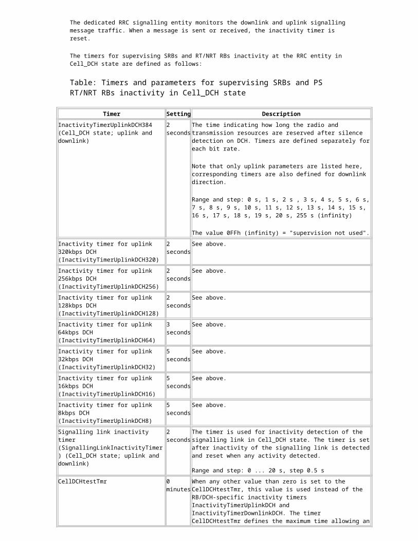
The RRC: Radio Bearer Release procedure is executed in Cell_DCH state prior to the state transition. After the RB release is completed, the UE is switched to Cell_FACH state by using the RRC: Radio Bearer Reconfiguration procedure, as presented in Figure State transition from Cell_DCH to Cell_FACH after the RRC: Radio Bearer Release procedure.

Figure: State transition from Cell_DCH to Cell_FACH after the RRC: Radio Bearer Release procedure
Transition from Cell_DCH state to PCH states
When the UE has an active PS connection and is transferred away from the Cell_DCH state (after releasing of the CS service or because of inactivity detection of PS RB(s)), the RNC performs direct switch to Cell/URA_PCH state, if all the PS RBs of the UE are inactive for a long time, or the L2 resources are at 'low' level. For more information, see Capacity, performance and overload control.
Capacity, performance and overload control
After the introduction of Cell/URA_PCH state, the average life span of the Iu connections will increase radically and the UE spends much more time in UTRA RRC connected mode than before . If the "always-ON" principle is used in the network, the mobiles nearly always are in UTRA RRC connected mode when they are switched on.
Sensible usage of the PCH states for the UEs in UTRA RRC connected mode decreases unnecessary releases and establishments of the signalling connections (RRC and Iu). Usage of PCH states clearly helps to avoid unnecessary signalling, and also internal processing in the whole network (that is, also avoids signalling overload), and shortens the setup-delays of the users actively using their services.

However, because of hardware-related resource restrictions, there is an absolute limit for the maximum number of simultaneous RRC connections. The Layer 3 load/resource handling procedure described here tries to maximise the profitable user traffic with limited hardware resources – and simultaneously takes into account that the network must never block the emergency calls.
Generally, it is very important to execute preventive load control by keeping enough safety margins to avoid more radical actions (for example, even the rejections of higher priority call establishments). Preventive actions help also to keep signalling delays shorter.
Layer 2 load/resource handling procedure
Layer 3 load/resource handling procedure
Transition from Cell_DCH state to idle mode
Transition from Cell_DCH state to idle mode is normally done, when the CN requests an Iu connection release, and the UE is not connected to another CN. Because of the Iu release request from the CN, the RNC releases the RRC connection. When the RRC connection is released, the UE is transferred to idle mode.
There are also other reasons for direct state transition from Cell_DCH state to idle mode, for example:
Radio link failure or loss of FP-level synchronisation is detected in Cell_DCH state and RRC connection re-establishment is not allowed.
Cell_FACH state cannot be used for that particular UE.
Radio link failure or loss of FP-level synchronisation detected in Cell_DCH state and RRC connection re-establishment not allowed
When all the active set radio links of the UE are in the "out of sync" state, and L1 synchronisation is not recovered within the time supervision, the RNC initiates a RRC connection re-establishment or RRC: RRC Connection Release procedure as described in Radio link failure.
When transport-bearer synchronisation loss is detected, the RNC initiates a RRC: Connection Re-establishment or RRC: Connection Release procedure, as described in Loss of FP-level synchronisation.
Cell_FACH state
As presented in the following figure, the Cell_FACH state is entered:
by transition from Cell_DCH state by transition from Cell_PCH state
by transition from URA_PCH state
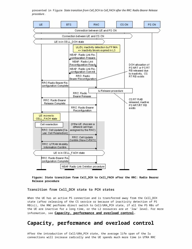
Figure: State transitions via the Cell_FACH state
In Cell_FACH state, the UE performs the following actions:
frequency division duplex (FDD) intra-frequency measurements and cell reselections inter-frequency/inter-RAT (radio access technology) measurements and cell reselections (note that FACH
measurement occasion [FMO] functionality is not supported by the RNC)
listens to all FACH transport channels on the selected secondary common control physical channel (S-CCPCH)
periodical cell updates (as defined by the timer T305)
if the UE is "out of service area" (out of coverage), it executes a cell reselection procedure, and runs timers T305 (periodical cell update), T317 (cell update when re-entering "in service area") or T307 (transition to idle mode when the UE detects "out of service area" after timer T305 has expired).
In the Cell_FACH state, the location of the UE is known at cell level in the RNC. A cell update procedure is used to report to the RNC when the UE executes cell reselection. In the Cell_FACH state, the cell update procedure replaces handover.
When the UE is switched to the Cell_FACH state (for example, Cell_DCH to Cell_FACH transition, paging the UE from the PCH states or by UE-initiated Cell/URA update), the RRC entity starts a supervision timer and waits for a periodic cell update. This timer is derived from UE parameters T305, T307, N302 and T302 (see Table UE timers and constants (on which the corresponding RNC timers are based) for “Out of Service Area” detection in Cell_FACH and Cell/URA PCH states).
If the UE is switched immediately back to the PCH states (for example, after the periodic update), the supervision timer is (re)started from the initial value, to wait for periodic cell update.
While the UE stays in the Cell_FACH state, the supervision timer is (re)started from the initial value, to wait for periodic cell update, each time a Cell/URA update is received from the UE.
If the UE - after inactivity detection in Cell_FACH state - is switched directly from Cell_DCH to the PCH states (via Cell_FACH state), the supervision timer is kept running to wait for periodic cell update.
Cell_FACH state internal procedures
Transition from Cell_FACH state to Cell_DCH state

Transition procedures from Cell_FACH state to Cell_DCH state
Transition from Cell_FACH state to Cell/URA_PCH state
Transition procedures from Cell_FACH state to Cell/URA_PCH state
Transition from Cell_FACH state to idle mode
Cell_FACH state internal procedures
Cell_FACH state is mainly a "transition state" which the UE enters from Cell_DCH or Cell/URA_PCH state, and leaves for Cell/URA_PCH or Cell_DCH states, or idle mode.
State transition from Cell_DCH state to Cell/URA_PCH state is performed through Cell_FACH state because of downlink/uplink inactivity. State transition to the opposite direction is performed because of uplink/downlink activity.
Cell_FACH state is also used to handle UE mobility (that is, Cell/URA updates) in common channel states, and for queuing of dedicated radio resources, or UE-specific layer 2 (DSP) resources.
The RRC entity allocates a cell-specific C-RNTI (Cell-RNTI) for the UE during a transition to Cell_FACH state. The C-RNTI is used as addressing information for all DCCH (dedicated control channel) and DTCH (dedicated traffic channel) data transmission through the RACH/FACH transport channels to/from the specific UE. After a successful transition from Cell_FACH state, the RRC entity releases the allocated C-RNTI.
UE-specific layer 2 resources can be released after the UE is switched to Cell/URA_PCH state. These resources must be (re)allocated before c-plane (DCCH) or u-plane (DTCH) data can be transferred in Cell_FACH state.
Data transmission in Cell_FACH state
Cell_FACH state is suitable for transmission of small user data packets in u-plane and NAS signalling messages in SRB3 and SRB4. Based on the current parameter default values with data volumes (data in RLC buffer) less than 128 bytes in u-plane and 1024 bytes in SRB3 and SRB4, RACH and FACH transport channels can be used for data transmission. For more information, see Procedures for packet data handling.
C-plane signalling in Cell_FACH state
Cell_FACH state is used also for "service establishment" for NRT RB (or NAS signalling sequence, for example, SMS, RAU/LAU) or RT call setup signalling when an inactive NRT service already exists, or there is a standalone signalling connection towards the PS-CN.
Cell update because of RLC unrecoverable error
If the number of retransmissions of the RLC RESET PDU exceeds the upper limit in UE-RLC, the UE sends a cell update message (with cause value "RLC unrecoverable error") to the RNC. The UE should indicate in the message whether the unrecoverable error exists in the signalling radio bearer SRB2, SRB3 or SRB4 or in another radio bearer (RB>4).
When this L2 signalling error occurs, the RNC initiates an RLC Re-establishment procedure for the UE.
Cell update because of cell reselection
When a cell update message is received from the UE during signalling or u-plane data transmission through another cell, the RRC entity allocates a new cell-specific temporary UE identity (C-RNTI), and switches the L2 routing towards the chosen cell.

Figure: Cell update because of cell reselection
The new C-RNTI is included in the RRC: Cell Update Confirm message, and after receiving this acknowledge and sending an RRC: UTRAN Mobility Information message to the RNC, the RNC and UE can start using the DCCH/DTCH mapped onto the RACH/FACH transport channels of the new serving cell.
The RRC entity updates the UE location information and restarts the periodic cell update supervision timer.
Periodic cell update
In practice, the time which an inactive UE is allowed to stay in Cell_FACH state, is much shorter than the interval for periodic updates (for the timer T305, the minimum possible value is 5 minutes), and thus the reception of the periodic cell update in Cell_FACH state can be considered as a failure situation. If, however, a periodic cell update in Cell_FACH state is received, the UE is immediately moved to the Cell_PCH state (if there is no suspended RRC procedure or data transfer (re)initiated to this UE).
Transition from Cell_FACH state to Cell_DCH state
State transition from Cell_FACH state to Cell_DCH state is performed, for example, because of the following reasons:
uplink/downlink data waiting for transmission establishment of a CS service (for example, AMR call setup)
use of RACH/FACH is prohibited (load reasons)
Uplink/downlink data waiting for transmission
The UE connection can be moved from Cell_FACH state to Cell_DCH state, if the RNC has user or control data waiting to be transmitted, or if the UE requests capacity. A transition occurs when a dedicated transport channel is established through explicit signalling.
The packet scheduler decides whether to allocate downlink and uplink capacity. It bases its decision on downlink traffic monitoring carried out by GTP or MAC entity, reception of measurement report message from the UE and RB type (NRT or RT).
For detailed description of downlink/uplink channel type selection, see Channel type selection.
Signalling connection establishment towards CS-CN

If the UE wants to send, for example, an SMS message (via CS-CN) or perform a NAS signalling transaction, the signalling connection is established towards the CS-CN. The RRC entity supervises the service establishment phase in the same way as in Cell_DCH state.
If the RAB must be established, for example, for adaptive multi-rate (AMR) calls, the UE is first switched to Cell_DCH state by using a RRC: Radio Bearer Reconfiguration procedure.
Transition procedures from Cell_FACH state to Cell_DCH state
The state transition from Cell_FACH state to Cell_DCH state can be done with several procedures, as specified in 3GPP TS25.331. In RU10 the RRC: Radio Bearer Reconfiguration and RRC: Radio Bearer Setup procedure is used for state transition from Cell_FACH to Cell_DCH.
An RRC: Radio Bearer Reconfiguration procedure (see Figure State transition from Cell_FACH to Cell_DCH with RRC: Radio Bearer Reconfiguration procedure) is used in all cases except when UE is in Cell_FACH state with PS service and new CS or PS RT connection is established. In that case an RRC: Radio Bearer Setup procedure is used (see Figure State transition from Cell_FACH to Cell_DCH with RRC: Radio Bearer Setup procedure as example of CS RT service establishment when UE is in Cell_FACH state with PS service).
If feature ‘HSPA Layering for UEs in Common Channels’ is activated, UEs are transferred to correct layer based on their HSDPA and HSUPA capability during a state transition from Cell_FACH to Cell_DCH state (see Figure Frequency layer change with state transition command from Cell_FACH to Cell_DCH). When the UE is either in Cell_FACH or Cell_PCH state, RNC has the information of UE HSDPA and HSUPA capability. For more information about the feature ‘HSPA Layering for UEs in Common Channels’, see WCDMA RAN RRM Handover Control.

Figure: State transition from Cell_FACH to Cell_DCH with RRC: Radio Bearer Reconfiguration procedure
Figure: State transition from Cell_FACH to Cell_DCH with RRC: Radio Bearer Setup procedure

Figure: Frequency layer change with state transition command from Cell_FACH to Cell_DCH
Transition from Cell_FACH state to Cell/URA_PCH state
Since the UE performs continuous reception of FACH in Cell_FACH state, it should be moved to the Cell_PCH state if there is not any data transmission or signalling activity for a while.
The state transition from Cell_FACH state to Cell_PCH state is performed for the following reasons:
inactivity detection in Cell_FACH state completion of Cell update/URA update procedure
Inactivity detection in Cell_FACH state
State transition to Cell/URA_PCH state because of the inactivity detection in Cell_FACH state is started when the MAC entity of the RNC indicates observed inactivity of NRT RAB(s) in uplink and downlink directions by sending the inactivity indication to the RRC entity.
PS RT RAB is inactive in common channel states (Cell_FACH, Cell/URA_PCH). State transition to Cell/URA_PCH state is allowed in the following situations:
The value of the MS activity supervision timer (MSActivitySupervision) is non-zero, indicating that Cell_PCH/URA_PCH states can be used and the UE has (inactive) PS NRT/RT-RAB(s).
The UE has only a standalone signalling connection towards the PS-CN and the initial value of the timer ‘Time supervision for inactive signalling connection’ towards the PS-CN (SignConnActivitySupervision) is non-zero, indicating that maintaining of an inactive signalling connection towards the PS-CN is allowed (and the PCH states are in use).
The UE supports the Cell/URA_PCH state.
If the above-mentioned criteria are fulfilled, the state transition from Cell_FACH state to Cell/URA_PCH state is started by the RRC entity when an inactivity indication is received from the MAC entity, and there is no RRC/RANAP procedure in progress.
Inactivity supervision is performed separately for the signalling connection to monitor signalling activity and for the PS RT/NRT-RAB(s) for data transmission activity, after the UE is switched to the PCH states.
The timers for supervising and controlling the state transition from Cell_FACH state to Cell/URA_PCH state are defined as follows:
Table: Timers for supervising and controlling the state transition from Cell_FACH state to Cell/URA_PCH state
Timer Setting Description
UL/DL activation timer (UL_DL_activation_timer) (Cell_FACH state; uplink and downlink)
2000 ms
This timer is used on MAC-c to detect idle periods on data transmission for the UE in Cell_FACH state.
Range and step: 50 ... 10000 ms, step 50 ms
ExtendedULDLActivationTmr 0 (zero) This parameter defines an extended Cell_FACH state inactivity supervision time used by the RNC (instead of the normal UL_DL_Activation_Timer obtained from the RNC-DB).
Range: 0...120s, step 1 s; 0 = ‘not in use’
MS activity supervision timer (MSActivitySupervision)
29 min This timer is used in RRC states Cell_PCH and URA_PCH for supervising the inactivity of PS RT/NRT RAB(s).
If the parameter value is set to zero, state transition to Cell_PCH/URA_PCH state is not allowed. When inactivity is detected in Cell_FACH state, the UE will be switched to the idle mode.
Range and step: 0 ... 1440 min, step 1 min
Time supervision for inactive signalling connection towards the PS-CN (SignConnActivitySupervision)
1 min This timer defines whether it is allowed to maintain an inactive signalling connection towards the PS-CN, and how long the RNC keeps the connection before the RANAP: Iu Release Request procedure.
Range and step: 0 (0 seconds), 1 (10 seconds), 2 (20 seconds), 3 (30 seconds), 4 (1 minute), 5 (2 minutes), 6 (5 minutes), 7 (10 minutes).
Default value: 4
CVUserInactInSignConnRel 1 (Yes) This parameter defines whether it is allowed to use the RANAP cause value ‘user inactivity’ in the RANAP: Iu Release Request procedure when the RNC is releasing an inactive signalling connection towards the PS-CN.
If this cause value is used, the SGSN is allowed to ignore the Iu release request (that is, the SGSN may decide whether to keep the Iu connection or release it immediately when the request is received from the RNC).
If the SGSN ignores the Iu release request, the RNC restarts the SignConnActivitySupervision. The UE is switched to the PCH state if there are no other activities (for example RT-service or signalling) in progress at this moment.
0 (No), 1 (Yes)
Completion of cell update procedure
The state transition from Cell_FACH state to Cell/URA_PCH state is done immediately (by using the RRC: Cell Update Confirm message or RRC: URA update Confirm message) after a successful Cell/URA update procedure because of cell reselection or periodic cell update if the UE was in Cell/URA_PCH before executing cell/URA update procedure. The target state after Cell/URA update procedure depends on the detection of UE mobility level (see Detecting the mobility level of UE ).

Transition procedures from Cell_FACH state to Cell/URA_PCH state
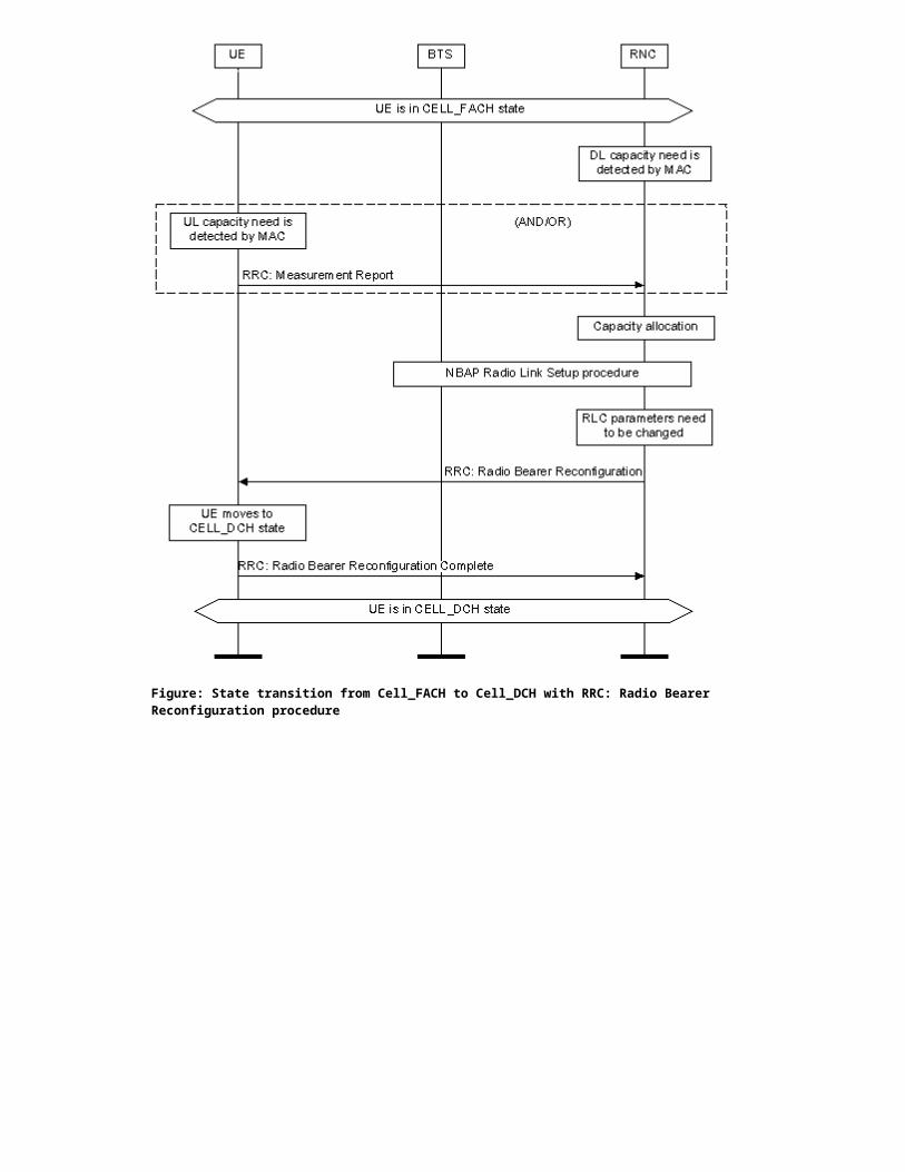
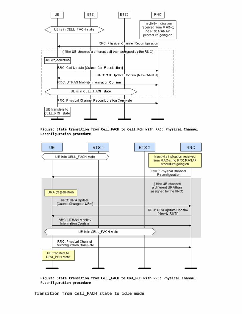
When the inactivity indication is received from the MAC, the RRC entity executes the state transition from Cell_FACH to the Cell/URA_PCH by sending an RRC: Physical Channel Reconfiguration message to the UE as presented in the Figures State transition from Cell_FACH to Cell_PCH with RRC: Physical Channel Reconfiguration procedure and State transition from Cell_FACH to URA_PCH with RRC: Physical Channel Reconfiguration procedure.
Figure: State transition from Cell_FACH to Cell_PCH with RRC: Physical Channel Reconfiguration procedure

Figure: State transition from Cell_FACH to URA_PCH with RRC: Physical Channel Reconfiguration procedure
Transition from Cell_FACH state to idle mode
The release of the RRC connection moves the UE to the idle mode. The RRC connection is released for the following reasons:
release of Iu-PS connection after releasing the last PS RAB (maintaining of a standalone signalling connection towards the PS-CN not allowed)
inactivity of the PS RT/NRT RB(s) detected in the Cell_FACH state and PCH states not used
absence of the UE detected in Cell_FACH state and time supervision for the receipt of "re-entered service area" indication from the UE is expired
Release of Iu-PS connection after releasing the last PS RAB
After releasing the last PS-RAB (or, for example, after a NAS signalling transaction), the PS-CN can decide to keep the existing Iu-PS connection for signalling purposes. In this case, there is no Iu release command received from the CN after the RANAP procedure (or signalling between the UE and the CN) is completed. The RNC supervises the resource release in this situation by using a separate supervision timer "Time supervision for inactive signalling connection" towards the PS-CN (SignConnActivitySupervision).
If the value of MS activity supervision timer (MSActivitySupervision) (see table Timers for supervising and controlling the state transition from Cell_FACH state to Cell/URA_PCH state) is non-zero and the UE has only a signalling connection towards the PS-CN, the RRC entity checks the initial value of the timer 'Time supervision for inactive signalling connection' towards the PS-CN (SignConnActivitySupervision) (see table Timers for supervising and controlling the state transition from Cell_FACH state to Cell/URA_PCH state). If the value of the timer is zero, the RRC entity initiates the release of the Iu-PS and RRC connections.
Release of inactive PS RB(s)
Release of inactive PS RT/NRT RB(s) starts when the MAC entity indicates observed inactivity in uplink and downlink directions by sending the inactivity indication to the RRC entity.
In receipt of this indication, the RRC entity checks if the initial value of the 'MS activity supervision timer' (MSActivitySupervision) (see table Timers for supervising and controlling the state transition from Cell_FACH state to Cell/URA_PCH state) timer is zero, indicating that Cell_PCH/URA_PCH states are not used. In this case the RRC entity initiates the release of the Iu and RRC connections.
Absence of the UE detected in Cell_FACH state
Detection of UE absence in Cell_FACH state concerns PS-CN and PS services only when the RRC entity has sent a downlink message, and no response is received from the UE during the RRC time supervision defined for the response. The RNC executes a local state transition to PCH states. In this case, there is no L2 routing to any cell, since a target cell is unknown. After this, the RNC uses the periodic ‘Cell/URA update wait’ timer for supervising resource release in case no "in service area indication" message is received from the UE. This timer is derived from UE parameters T305, T307, N302 and T302 (see Table UE timers and constants (on which the corresponding RNC timers are based) for “Out of Service Area” detection in Cell_FACH and Cell/URA PCH states. Downlink data and direct transfer messages received from the PS-CN are buffered while the UE is in "out of service area". Delay or service interruption caused by the "out of service area" is not allowed for CS RT services. If no response is received from the UE during the normal L3 time supervision (or a "RLC unrecoverable error" is detected in the NAS signalling), the Iu-CS connection is released already at this stage.
L2 signalling error in Cell_FACH state
When the "RLC unrecoverable error" is detected by the UE in Cell_FACH state, the UE sends a cell update message (with the cause value "RLC unrecoverable error") to the RNC. When this indication about an L2 signalling error occurs and this indication concerns u-plane RB, that is, >RB4, or c-plane RB, <RB5, the RNC initiates an RLC re-establishment procedure for the UE and the L2 of the RNC. If "RLC unrecoverable error" is detected internally in the RNC, it is indicated to the RRC entity. When the error is indicated in u-plane and/or c-plane RB, the RRC entity initiates the RLC re-establishment procedure for the UE and the L2 of the RNC when the UE sends a Cell Update message.
Cell_PCH state
The Cell_PCH state is characterised by the following:

No dedicated physical channel is allocated to the UE. The UE uses discontinuous reception (DRX) for monitoring a paging channel (PCH) through an allocated
paging indicator channel (PICH).
No uplink activity is possible.
No C-RNTI is allocated for the UE.
The location of the UE is known by the RRC layer of the RNC at cell level according to the cell where the UE last made a cell update. In the Cell_PCH state, the UE:
monitors the paging occasions according to the DRX cycle and receives paging information on the PCH listens to the BCH (broadcast channel) transport channel of the serving cell for the decoding of system
information messages
initiates a cell update procedure on cell change
initiates a cell update procedure because of periodic cell update the after timer T305 expires in the UE
initiates a cell update procedure because of uplink data transmission
If the UE is in "out of service area" (out of coverage), it executes a cell reselection procedure and runs timers T305 (periodical cell update) and T316 (out of service in PCH states).
When the UE is transferred from Cell_FACH state to Cell_PCH state, and if not already running, the RRC entity starts a supervision timer to wait for a periodic Cell/URA update. This timer is derived from UE parameters T305, T307, N302 and T302 (see Table UE timers and constants (on which the corresponding RNC timers are based) for “Out of Service Area” detection in Cell_FACH and Cell/URA PCH states, and it is stopped when the UE transfers (or is switched) to the Cell_FACH state, and (re)started when the UE is switched (back) to the PCH states.
UE-specific layer 2 resources can be released after the UE is switched to Cell_PCH state. For more information, see Layer 2 load/resource handling procedure in Capacity, performance and overload control.
The dedicated control channel (DCCH), which is one of the logical channels, cannot be used in this state. If the network wants to initiate activity, it makes a paging request on the paging control channel (PCCH), which is one of the logical channels in the known cell to initiate downlink activity.
The UE is transferred to Cell_FACH state either by a command (paging) from RNC or through any uplink access, which initiates the cell update procedure.
The release of an RRC connection is not possible in the Cell_PCH state. The UE first moves to Cell_FACH state to perform the release signalling. When the RNC initiates a RRC connection release, the UE is first transferred from Cell_PCH state to Cell_FACH state with paging procedure and the RRC connection release is executed in Cell_FACH state.
URA_PCH state
URA_PCH state is very similar to Cell_PCH state. Basically the difference is that UE executes URA Update when URA area changes and when paging is needed to be initiated it is sent to all cells within the URA area.
The URA_PCH state is characterized by the following:
No dedicated channel is allocated for the UE The UE uses DRX for monitoring a PCH through an allocated PICH
No uplink activity is possible
The location of the UE is known by UTRAN Registration Area level according to the URA where the UE last made a URA update. In URA_PCH state, the UE:
listens to the PCH transport channel for the decoding of paging and notification messages sent by the RAN,
listens to the BCH transport channel of the serving cell for the decoding of system information messages,
initiates a URA updating procedure on URA change,

initiates a periodic URA update after timer T305 has expired in UE (if configured),
initiates a Cell Update in case of paging response (via FACH state),
initiates a Cell Update in case of UL data transmission (If the UE needs to transmit anything to the RNC, it moves to the Cell_FACH state and executes a RRC: Cell Update procedure).
When UE is detected as fast moving, see Detecting the mobility level of UE, it is transferred to URA_PCH instead of Cell_PCH, where fast moving UE is causing continuously unnecessary signaling (cell is changing rapidly). If not already running, the RRC entity starts a supervision timer to wait for a periodic URA update. Handling of the timer is as in Cell_PCH state, see Cell_PCH state.
UE-specific layer 2 resources can be released after the UE is switched to URA_PCH state. For more information, see Layer 2 load/resource handling procedure in Capacity, performance and overload control.
The URA contains a set of cells. UE reads URA-identities from the broadcast channel. The mobility in this state is handled by RRC: URA Update procedure. There is no dedicated channel allocated for the UE in URA_PCH state.
UE uses discontinuous reception (DRX) and monitors paging messages from RNC. If the network wants to initiate any downlink activity, it needs to make a paging request in all cells on the PCCH logical channel within the URA where the location of the UE is known.
Any activity causes the UE to be transferred to Cell_FACH state either by a command (paging) from RNC or through any uplink access, which initiates the cell update procedure.
The release of an RRC connection is not possible in the URA_PCH state. The UE first moves to Cell_FACH state to perform the release signalling. When the RNC initiates a RRC connection release, the UE is first transferred from URA_PCH state to Cell_FACH state with paging procedure, and the RRC connection release is executed in Cell_FACH state.
Definition of the primary/secondary URAs
Eight different URAs can be defined for each cell. The first URA ID in the URA list of the cell is a Primary URA, which is assigned to the UE in this cell when the UE is registered on this URA.
The rest of the URA IDs in the URA list are Secondary URAs (URA IDs of the neighbouring/overlapping URAs to which the cell belongs to), which are broadcast on BCH of this cell.
Figure: Overlapping UTRAN Registration Areas
The figure above illustrates a definition of three overlapping URAs with the primary and the secondary URA IDs given for each cell:
URA1 includes the cells A, B, D, E, F, G, H and I URA2 includes the cells B, C, F, G, I and J
Cells F, G and I are URA2 cells, which overlap on URA1 (ID of the secondary URA defined as URA1)
Cell B is the URA1-cell overlapping on URA2, etc.
When the UE performs an URA Update through the cell D, the URA identity of URA1 is assigned to this UE (the UE is registered on URA1). If the UE is paged, the paging procedure must be executed, not only through the cells with the Primary URA-ID defined as URA1, but also through the overlapping (Secondary URA-ID) URA2-cells (F, G and I).
If the UE moves from URA1 to URA2 via the cells F and G (route: D=>E=>F=>G), the RRC:URA Update procedure is not initiated since the URA identity of URA1 is broadcast in these URA2-cells and the UE stays registered on URA1.
When the UE registered on URA2 moves to the opposite direction (route: G=>F=>E=>D), the URA Update is initiated when the UE selects the Cell E and the RNC registers the UE on URA1.
Paging (transition to Cell_FACH)
If the RRC entity has downlink signalling messages, or L2 indicated that there is downlink u-plane data in the RLC buffers to be sent to UE, the RRC entity initiates the paging procedure.
As a response to the paging procedure, the UE starts a cell update procedure. A cell update procedure can also start because of uplink data transmission in Cell/URA_PCH state.
The RNC also accepts a cell update with a cause different than paging response as a valid paging response, even if this response comes through a different cell than the UE originally was paged from.
Figure: Cell update because of paging response
The RNC responds with a 'RRC: Cell Update Confirm' message (the UE is in this case kept in Cell_FACH state), updates the location information of the UE and continues the suspended downlink procedure (for example, initiation of downlink data transfer). Note, however, that the RRC connection release can be initiated immediately without sending a 'RRC: Cell Update Confirm' message to the UE.
The Cell/URA updates received through the Iur during the paging procedure are handled separately. Depending on the received cause value and/or relocation support of the target RNC (and involved CN nodes), the RRC entity initiates a SRNS relocation, RRC connection release, or directed signalling connection re-establishment (DSCR) procedure. For more information, see Description of SRNS relocation.
If the UE is not reached with the first paging procedure, the RRC entity repeats the paging procedure. This paging retransmission is executed as defined by RNC management parameters 'Repetition interval of the first repeated connected mode paging procedure' (PageRep1stInterv) and 'Repetition interval of the second repeated connected mode paging procedure' (PageRep2ndInterv).
The parameters for controlling paging retransmission are defined in the following table.
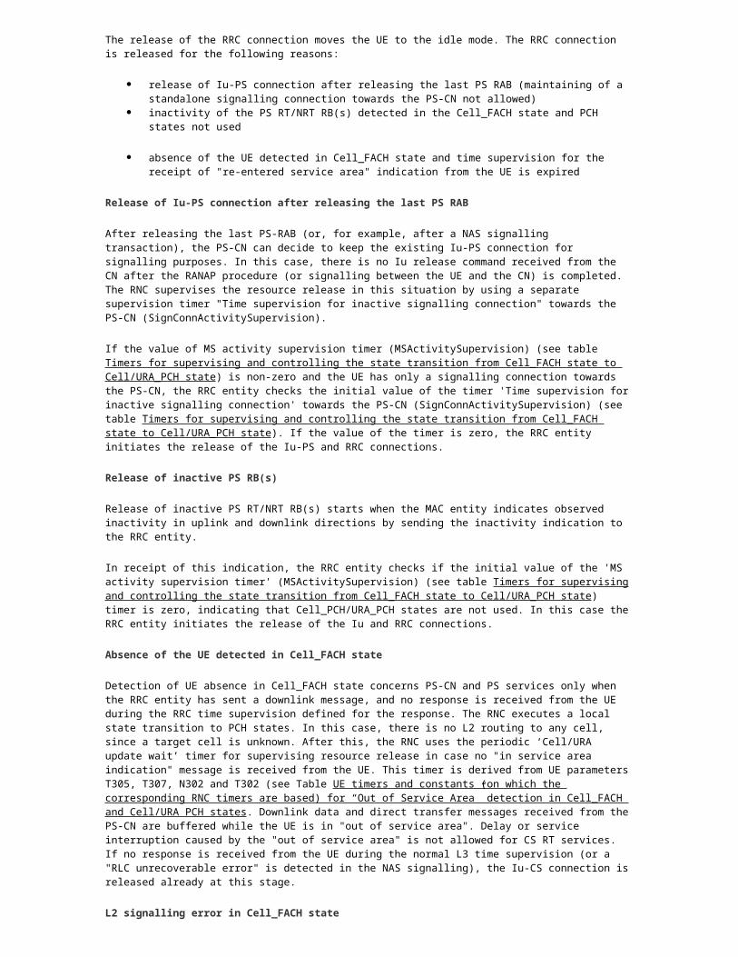
Table: Timers for controlling paging retransmission procedure for UTRA RRC connected mode UE
Parameter Default value
Definition
PageRep1stInterv 700ms The time interval between the first paging procedure and the first repeated paging procedure when no response (cell update with a cause value, for example, ‘Paging Response’) is received from the UE within the time supervision.
Value zero means that the paging procedure is not repeated.
PageRep2ndInterv 2000ms The interval between the first and the second repeated paging procedures.
If the value of PageRep1stInterv is set to zero, the RRC entity interprets also the PageRep2ndInterv as zero (regardless of the real value of the parameter).
Note The operator must set the parameters controlling paging retransmission, so that the repeated UTRAN-originated paging procedure covers the whole duration of the cell (re)selection procedure (in URA_PCH state) of the different mobile stations in the network.
Coordination of the UTRAN-originated and the CN-originated paging procedures
While the UE is in Cell_PCH or URA_PCH state, the RRC entity stores the information received in the latest RANAP: Paging procedure from the CS-CN. Paging retransmission is also used for the CN-originated paging procedures while the UE is in the PCH states.
If an UTRAN-originated paging procedure is in progress when the paging request is received from the CS-CN, the RRC entity initiates a RRC: Paging Type2 procedure by using the stored information when the UE sends a response to the UTRAN originated paging procedure in Cell_FACH state.
If the RANAP paging request is received while the UE is in "out of service area" (that is, no response received to the second repeated paging procedure), the RRC entity forwards the CS-CN page request to the UE, and stores the information received from the CN. If the RANAP paging request is received while a UTRAN-originated paging procedure is in progress, the RRC uses the information received from the CS-CN in the RRC: Paging Type1 procedure for the rest of the paging retransmissions.
If downlink data/signalling is received from the PS-CN while a CS-CN originated paging procedure is in progress, the RRC entity uses the information received from the CS-CN in the RRC: Paging Type1 procedure during the whole paging retransmission.
Paging retransmission and “Out of Service Area” detection in PCH states
When the RRC entity executes the first repeated UTRAN-originated paging procedure and no response (cell update) is received from the UE, the RRC entity starts the supervision timer based on the UE timer T316. The UE is allowed to be T316 seconds in "out of service area" without indicating this to the RNC. When the supervision timer expires, the RRC entity executes the second repeated UTRAN originated paging procedure for this UE, and waits for a paging response from the UE.
When the RRC entity executes the second repeated UTRAN-originated paging procedure and no response (cell update) is received from the UE, the RRC entity uses the periodic 'Cell/URA update wait' timer (derived from UE parameters T305, T307, N302 and T302) for supervising the resource release. When this timer expires, all reserved resources for this UE are released.
The UE timers (on which the corresponding RNC timers are based) for "out of service area" detection in Cell_FACH and Cell/URA_PCH states are defined in the following table.
Table: UE timers and constants (on which the corresponding RNC timers are based) for “Out of Service Area” detection in Cell_FACH and Cell/URA PCH states
Timer Setting Description
T316 30 seconds
This timer is started when the UE detects an "out of service area" in URA_PCH or Cell_PCH state. When the timer ("in service area" not detected) expires, the UE enters Cell_FACH state (and starts timer T317 if "out of service area" is still detected).
T317 180 This timer is started when the UE detects an "out of service area" in Cell_FACH state. When the timer

Timer Setting Description
seconds (in service area not detected) expires, the UE enters the idle mode.
The UE implementing REL4 3GPP TS 25.331 specification interprets all values of T317 as infinite.
T305 30 minutes
Periodic Cell/URA update timer
T307 30 seconds
Timer for transition to idle mode, when the timer T305 expires, and the UE detects an "out of service area".
T302 2000 ms Cell/URA update retransmission timer
Note!
The minimum value of this timer is limited to 1000 ms
N302 7 Cell/URA update retransmission counter
Note!
This parameter has a permanent value of 7 set by the system.
Out of service area detection procedures in the UE
If the UE detects "out of service area" in Cell_FACH state (unsuccessful cell (re)selection procedure), the UE starts the timer T317 and continues the cell selection procedure. Note that the UE implementing REL4 3GPP TS 25.331 specification or later interprets all values of T317 as infinity and the UE enters the idle mode only after timers T305 and T307 expire.

Figure: Out of service area detection procedure in 3GPP specifications
The procedure in Cell/URA_PCH state is generally the same as in Cell_FACH state, except that the UE uses the timer T316 instead of T317. If timer T316 expires before the UE succeeds to find a suitable cell, the UE enters the Cell_FACH state, starts timer T317, and continues the cell selection procedure as in Cell_FACH state.
Cell/URA update (transition to Cell_FACH)
In 3GPP TS 25.331, the cell update causes are defined in a priority order, and thus one cause value can include more than one reason for cell update. Possible cell update cause values and their priority order are listed in the following table.
Table: Priority order and interpretation of the cell update cause values
Cause value Possible reason for cell update
1 2 3 4 5 6 7
1 Uplink data transmission x x x x x
2 Paging response x x x x x
3 Radio link failure x x

Cause value Possible reason for cell update
1 2 3 4 5 6 7
4 Re-entering service area x x x x
5 RLC unrecoverable error x x
6 Cell reselection x x
7 Periodical cell update x
In 3GPP TS 25.331, there are only two URA update causes. Possible URA update cause values and their priority order are listed in the table below.
Table: Priority order and interpretation of the URA update cause values
Cause value Possible reason for URA Update
1 2
Change of URA x x
Periodical URA update x
The UE can send consecutive Cell/URA update messages when a different criterion is met. Handling of the cell update cause in the RNC depends on the significance of the received cause value.
For Cell/URA update retransmission procedure, the UE uses parameters T302 and N302. The cell update procedure is repeated N302 times in interval of T302. If the UE does not receive the answer (a RRC: Cell Update Confirm message) from the RNC during the retransmission procedure, the UE transfers to the idle mode.
Uplink access
When the UE is in Cell_PCH (or URA_PCH) state and the UE has uplink data to send, it initiates a cell update procedure with cause value "uplink data transmission" prior to the uplink data transfer.
After the cell update procedure is completed, the UE remains in Cell_FACH state. The UE can also be transferred directly to Cell_DCH state by RRC: Cell Update Confirm (see Transition from Cell/URA_PCH state to Cell_DCH state).

Figure: Cell update because of uplink data transmission
Periodic cell/URA update
The MS activity supervision timer (MSActivitySupervision) is always checked when the Cell/URA update message is received from the UE. The UE is immediately transferred back to Cell_PCH or URA_PCH state after the procedure is completed.
Figure: Periodic cell update
No paging procedure is triggered when the MS activity supervision timer (MSActivitySupervision) expires. User inactivity detection and a transition to the idle mode are based on the indications received from the UE.
When the UE is switched to Cell/URA_PCH state, the RRC entity starts a supervision timer (based on UE timer T305) for receipt of a periodic Cell/URA update.

If the Cell/URA update cause in the Cell/URA update message is 'periodic Cell/URA update', the RRC entity updates the UE location information and restarts the periodic ‘Cell/URA update wait’ timer if the UE is immediately switched back to the PCH states.
If the MS activity supervision timer (MSActivitySupervision) expires when the Cell/URA update message is received from the UE, the RRC entity initiates the RANAP: Iu Release Request procedure towards the PS-CN (CN is informed about the user inactivity). The PS-CN can ignore the initiated Iu release without sending a response to the RNC. In this case, the Iu-PS connection remains, state transition from Cell_FACH state to Cell/URA_PCH state is initiated, and the MS activity supervision timer (MSActivitySupervision) is restarted.
If a response to the Iu release request is received from the CN, the Iu connection is released and a RRC: RRC Connection Release procedure is initiated. After this, the UE transfers to the idle mode. This transition is made through the Cell_FACH state.
Transition from Cell/URA_PCH state to Cell_DCH state
State transition directly from Cell/URA_PCH to Cell_DCH can be made by using Cell Update confirm procedure. This is suitable for the following scenarios:
When DL data exceeding the Cell_FACH threshold on PS NRT RAB. When DL data transfer is started again on PS RT RAB.
When UL data transmission with Traffic Volume Indicator as TRUE is indicated by RRC: Cell Update message.
When the location service request with geographical measurements is received from CN.
The RNC decides on the basis of radio conditions whether it can transfer UE directly to Cell_DCH state with the RRC: Cell Update Confirm message. UE informs the CPICH Ec/No measurement result in the RRC: Cell Update message. Based on that RNC decides whether to use the direct state transition to Cell_DCH state or first take the UE in Cell_FACH state from where the UE can be transferred to Cell_DCH state.
Table: Parameters for using RRC: Cell Update Confirm for direct state transition from Cell/URA_PCH to Cell_DCH
Parameters Setting Description
Direct State Transition From Cell_PCH to Cell_DCH (CUCforPCHtoDCHallowed)
1 (true)
The direct state transition from Cell/URA_PCH to Cell_DCH activation.
The parameter defines if it is allowed to move UE directly from Cell/URA_PCH to Cell_DCH by using RRC: CELL UPDATE CONFIRM message.
Range: 0 (false), 1 (true)
CPICH Ec/No Threshold Value For CUC Usage (CUCEcNoThreshold)
25 (corresponding the measured quantity value of ~ -9dB for CPICH Ec/Io)
The parameter defines the threshold value which is compared to CPICH Ec/No measurement value received from the UE in Cell Update message.
The threshold is used to estimate if the quality of radio-path is good enough for using the RRC: CELL UPDATE CONFIRM message and UM RLC-SAP to transfer the UE directly from Cell/URA_PCH state to Cell_DCH state or not.
If the reported CPICH Ec/No < CUCEcNoThreshold, the Radio Bearer Reconfiguration procedure and AM RLC-SAP is used for the state transition procedure.
Range: 0 … 49, step 1
Downlink traffic volume low threshold for GTP-entity (TrafVolThrDLLowGTP)
128 bytes This parameter defines, in bytes, the lower traffic volume threshold of buffered RAB/tunnel-specific data in the GTP-entity for the UE in Cell/URA_PCH state. Based on this trigger UE can be transferred directly to Cell_DCH state
Range: 0 (0 bytes), 8 (8 bytes), 16 (16 bytes), 32 (32 bytes), 64 (64 bytes), 128 (128 bytes), 256 (256 bytes),

Parameters Setting Description
512 (512 bytes), 1024 (1 KB)
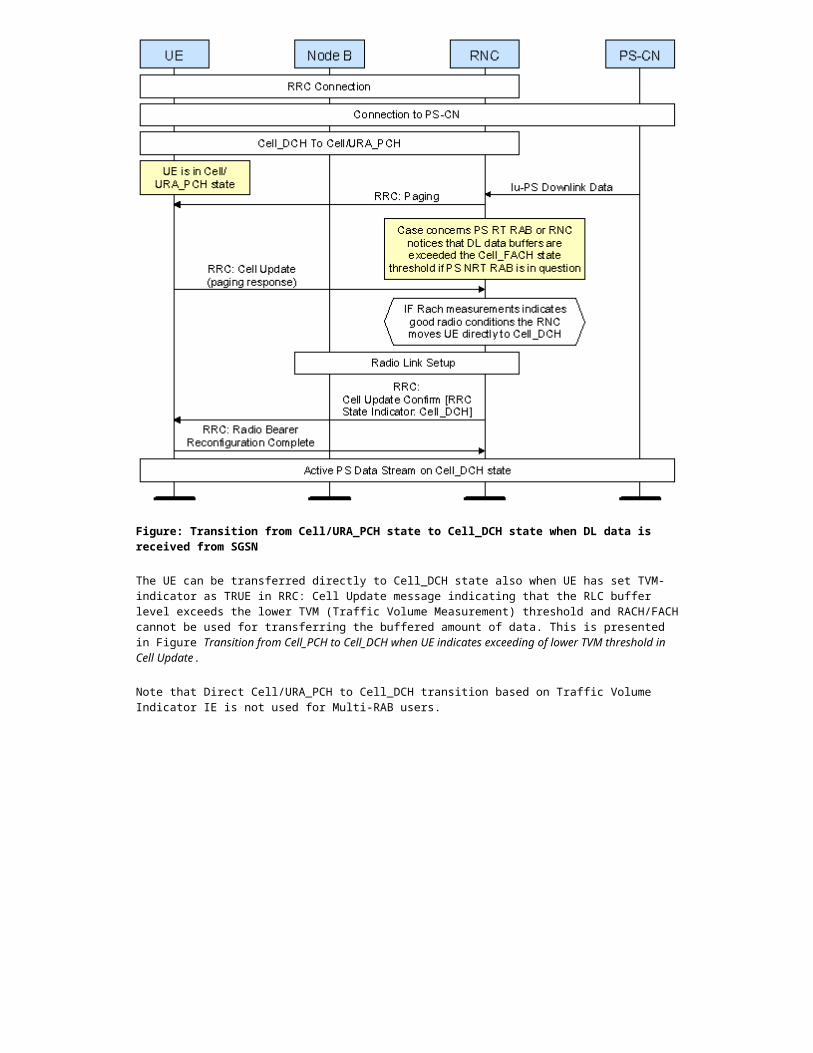
The UE can be transferred directly to Cell_DCH state when the PS-CN sends immediately a large enough amount of DL data that the Cell_FACH state traffic volume threshold is exceeded. This functionality is presented in Figure Transition from Cell/URA_PCH state to Cell_DCH state when DL data is received from SGSN.
Figure: Transition from Cell/URA_PCH state to Cell_DCH state when DL data is received from SGSN
The UE can be transferred directly to Cell_DCH state also when UE has set TVM-indicator as TRUE in RRC: Cell Update message indicating that the RLC buffer level exceeds the lower TVM (Traffic Volume Measurement) threshold and RACH/FACH cannot be used for transferring the buffered amount of data. This is presented in Figure Transition from Cell_PCH to Cell_DCH when UE indicates exceeding of lower TVM threshold in Cell Update.
Note that Direct Cell/URA_PCH to Cell_DCH transition based on Traffic Volume Indicator IE is not used for Multi-RAB users.

Figure: Transition from Cell_PCH to Cell_DCH when UE indicates exceeding of lower TVM threshold in Cell Update
When the location service request with geographical measurements is received from CN the measurements are done in Cell_DCH which will lead to RRC state transition procedure. This is presented in Figure Transition from Cell/URA_PCH to Cell_DCH when location service request received from CN.

Figure: Transition from Cell/URA_PCH to Cell_DCH when location service request received from CN
Transition from Cell_PCH state to URA_PCH state
To reduce unnecessary signalling (cell re-selections), the UE is moved to URA_PCH state when it has been detected as fast moving UE (see Detecting the mobility level of UE). The transition is made through Cell_FACH state.
Transition from URA_PCH state to Cell_PCH state
To reduce unnecessary paging signalling, the UE is moved to the Cell_PCH state when it has been detected as slow moving UE (see Detecting the mobility level of UE). The transition is made through Cell_FACH state.
Detecting the mobility level of UE
When the UE is Cell_DCH state, its location is known at cell level. The Handover Control detects the high mobility of UE by counting the active set changes needed for the UE.
If UE is detected as fast moving UE already in Cell_DCH state it is also used to predict the fast movement of UE in Cell_FACH and Cell_PCH state.
In Cell_FACH and Cell_PCH state the UE behaviour is also supervised by a counter, which counts the number of cell updates because of cell reselections. When the number of cell reselections has exceeded the limit defined by the management parameter ‘MaxCellReselections‘ in the time window defined by management parameter ‘CellReselectionObserving Time’ (see Table Timer for user inactivity detection in Cell_PCH state), the UE is detected as fast moving.

When moving the UE from Cell_FACH state to PCH states or after cell reselection triggers in Cell_PCH state, this information and the information received from Handover Control is used to define the target RRC state (Cell_PCH or URA_PCH).
When the UE is in URA_PCH state RNC observes the changes of the Cell_IDs. When Cell/URA update message is received from the same cell predefined number of times consecutively, RNC interprets the UE as slow moving UE. When target PCH state is evaluated the RNC transfers UE to Cell_PCH state instead of URA_PCH state.
Table: Parameters for detecting the high mobility of UE in Cell_FACH or Cell_PCH state
Parameters Setting Description
Max cell reselections (MaxCellReselections)
3 times
The maximum allowed number of cell reselections during Cell Reselection Observing Time in Cell_FACH or Cell_PCH state before transition to URA_PCH state.
The number of cell reselections is counted in both Cell_FACH and Cell_PCH states. When the UE is in Cell_FACH state, the value of the Max cell reselections (MaxCellReselections) during Cell Reselection Observing Time (CellReselectionObservingTime) is used when deciding a target state after the MAC-c entity has sent an inactivity indication to L3.
The value ‘0’ means that the URA_PCH state is "disabled".
Range and step: 0 ... 100 times, step 1 times
Cell Reselection Observing Time (CellReselectionObservingTime)
16 min
The timer is set when the first Cell Update message because of 'cell reselection' is received while UE is in CELL_FACH or CELL_PCH state. In expiry of the timer, the counter MaxCellReselections is reset.
Range and step: 1..60, step 1 min
Transition from Cell/URA_PCH state to the idle mode (via Cell_FACH state)
State transition from Cell/URA_PCH state to the idle mode is done for the following reasons:
release of inactive PS RT/NRT RAB(s) (user inactivity) signalling connection inactivity detection (release of inactive standalone signalling connection
towards PS-CN)
periodic cell update not received during the time supervision
Release of inactive PS RT/NRT RAB(s)
When a Cell/URA update is received from the UE in Cell/URA_PCH state and this procedure does not lead to any further (NAS) signalling/data transmission activity, the RRC entity checks the status of the MS activity supervision timer (MSActivitySupervision).
If the MS activity supervision timer (MSActivitySupervision) expires and the Cell/URA update procedure does not cause any signalling or data transmission activities (for example, because of a pending downlink procedure), the release of this UE's resources (because of user inactivity) is initiated.

Figure: Transition to idle mode because of user inactivity
The timer for supervising transition from Cell/URA_PCH state to idle mode because of the release of inactive PS RT/NRT RAB(s) is defined as follows:
Table: Timer for user inactivity detection in Cell_PCH state
Timer Setting Description
MS activity supervision timer (MSActivitySupervision)
29 min This timer is used in RRC states Cell_PCH and URA_PCH for supervising the inactivity of NRT RAB(s).
Range and step: 0 ... 1440 min, step 1 min

Figure: Attempt to release the resources because of user inactivity (ignored by the CN)
If the PS-CN ignores the Iu Release Request sent by the RNC (that is, the Iu release command message is not received during the time supervision), the transition from Cell_FACH back to the Cell_PCH/URA_PCH state is executed. After the state transition is completed, the MS activity supervision timer (MSActivitySupervision) is restarted again.
The RRC entity first checks if the number of counted cell reselections exceeds the threshold value defined by ‘Max cell reselections’ (MaxCellReselections) during time defined by Cell Reselection Observing Time (CellReselectionObservingTime) before initiating a state transition procedure. If the UE is moved to the URA_PCH state, the ‘Max cell reselections’ (MaxCellReselections) is reset.
The parameters for detecting the high mobility of UE are defined in Table Parameters for detecting the high mobility of UE in Cell_FACH or Cell_PCH state.
Release of inactive standalone signalling connection towards PS-CN
When the UE with a standalone signalling connection (that is, no PS RT/NRT-RAB(s)) towards the PS-CN is switched to the Cell/URA_PCH state, the RRC entity supervises the inactive Iu-PS connection by using the timer ‘Time supervision for inactive signalling connection towards the PS-CN’ (SignConnActivitySupervision).
When there is a NAS signalling sequence executed between the UE and the PS-CN, the supervision timer is zeroed. After the UE is switched back to the PCH states (no PS RT/NRT-RAB(s)), the ‘Time supervision for inactive signalling connection’ towards the PS-CN (SignConnActivitySupervision) is started again.
If a PS RT/NRT-RAB setup is executed before the supervision timer ‘Time supervision for inactive signalling connection towards the PS-CN’ (SignConnActivitySupervision) expires, the RRC entity stops the inactivity supervision.
When the timer ‘Time supervision for inactive signalling connection towards the PS-CN’ (SignConnActivitySupervision) expires, the RRC entity initiates a paging procedure. When the response to the paging procedure is received from the UE, the RRC executes the RANAP: Iu Release Request procedure towards the PS-CN.
Note When releasing an inactive standalone signalling connection, the cause value 'user inactivity' in the RANAP: Iu Release Request procedure can be enabled by a management parameter CVUserInactInSignConnRel.
The timer for supervising the transition from Cell/URA_PCH state to idle mode because of the release of an inactive standalone signalling connection towards PS-CN, and the usage of the cause value in RANAP: Iu Release Request procedure are defined as follows:
Table: Parameters for supervising standalone inactive signalling connection towards PS-CN
Timer Setting Description
Time supervision for inactive signalling connection towards the PS-CN (SignConnActivitySupervision)
1 min This timer defines whether it is allowed to maintain an inactive signalling connection towards the PS-CN and how long the RNC keeps the connection before the RANAP: Iu Release Request procedure.
Range and step: 0 (0 seconds), 1 (10 seconds), 2 (20 seconds), 3 (30 seconds), 4 (1 minute), 5 (2 minutes), 6 (5 minutes), 7 (10 minutes).
Default value: 4
CVUserInactInSignConnRel 1 (Yes) This parameter enables the RANAP cause value ‘user inactivity’ in the RANAP: Iu Release Request procedure when the RNC releases an inactive signalling connection towards the PS-CN.
If this cause value is used, the SGSN is allowed to ignore the Iu release request (that is, the SGSN may decide whether to keep the Iu connection or release it immediately when the request is received from the RNC).
If the SGSN ignores the Iu release request, the RNC restarts the 'SignConnActivitySupervision'. The UE is switched to the PCH state if there are no other activities (for example RT-service or signalling) in progress at that moment.
0 (No), 1 (Yes)
Periodic Cell/URA update is not received during the time supervision
When the periodic 'Cell/URA update wait' timer (no periodic Cell/URA update received) expires, the RRC entity initiates the RANAP: Iu Release Request procedure (cause value: 'radio connection with UE lost') towards the PS-CN, and all reserved resources for the UE are released. After this, if there is a cell update received from the UE, the UE will be unknown and the RRC connection is released by using cause value 'DSCR'.
Cell/URA update over Iur
The descriptions of Cell/URA updates over Iur in the following two sections do not give all the details. For a more detailed description of SRNS relocation procedures in different RRC states, and parameter settings related to this feature, see Description of SRNS relocation.

Cell update over Iur
URA update over Iur
Cell update over Iur
If the UE starts a cell update procedure in a RNC (new controlling RNC) other than the serving RNC (SRNC), the information included in the RRC: Cell Update message is transferred to the SRNC over Iur interface with an uplink signalling transfer procedure.
Figure: Cell update over Iur
The handling of cell update over Iur in the SRNC depends on the cause value in the cell update message.
Note When the SRNC Relocation procedure is not supported by the target RNC or by the involved CN node(s), the source RNC initiates a directed signalling connection re-establishment (DSCR) procedure over Iur.
In Figure Cell update over Iur, initiation and completion of a SRNC Relocation procedure because of cell update under another RNC than SRNC is presented.
After the SRNC relocation procedure is performed, and the DRNC (drift RNC) becomes the SRNC, it continues executing the cell update procedure.

URA update over Iur
The URA update procedure is normally used by the UE to inform the RNC that the UE switched to a new URA (UTRAN registration area). In this case, the procedure is triggered after cell change and after the UE decoded the URA identifier(s) valid in that cell (and no URA identifier stored in the UE is found) from the BCH.
Figure: URA update over Iur interface
The procedure can also be triggered when a URA update periodicity timer (T305) in the UE expires.
When the UE in URA_PCH state moves to the area of another RNC than the serving RNC, it triggers a URA update procedure towards this target RNC.
In this case, the DRNC forwards the received URA update message to the SRNC and the SRNC can initiate SRNS relocation, or an alternative procedure based on this URA update message.
After the SRNS relocation, the UE is always moved to Cell_PCH state.

Transition from Cell/URA_PCH state to the idle mode (via Cell_FACH state)
State transition from Cell/URA_PCH state to the idle mode is done for the following reasons:
release of inactive PS RT/NRT RAB(s) (user inactivity) signalling connection inactivity detection (release of inactive standalone signalling connection
towards PS-CN)
periodic cell update not received during the time supervision
Release of inactive PS RT/NRT RAB(s)
When a Cell/URA update is received from the UE in Cell/URA_PCH state and this procedure does not lead to any further (NAS) signalling/data transmission activity, the RRC entity checks the status of the MS activity supervision timer (MSActivitySupervision).
If the MS activity supervision timer (MSActivitySupervision) expires and the Cell/URA update procedure does not cause any signalling or data transmission activities (for example, because of a pending downlink procedure), the release of this UE's resources (because of user inactivity) is initiated.
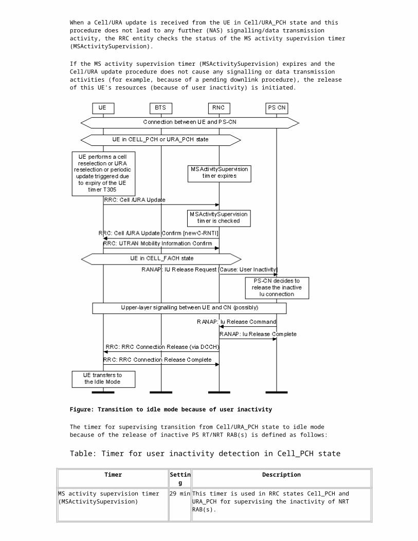
Figure: Transition to idle mode because of user inactivity
The timer for supervising transition from Cell/URA_PCH state to idle mode because of the release of inactive PS RT/NRT RAB(s) is defined as follows:
Table: Timer for user inactivity detection in Cell_PCH state
Timer Setting Description
MS activity supervision timer (MSActivitySupervision)
29 min This timer is used in RRC states Cell_PCH and URA_PCH for supervising the inactivity of NRT RAB(s).
Range and step: 0 ... 1440 min, step 1 min
Figure: Attempt to release the resources because of user inactivity (ignored by the CN)
If the PS-CN ignores the Iu Release Request sent by the RNC (that is, the Iu release command message is not received during the time supervision), the transition from Cell_FACH back to the Cell_PCH/URA_PCH state is executed. After the state transition is completed, the MS activity supervision timer (MSActivitySupervision) is restarted again.

The RRC entity first checks if the number of counted cell reselections exceeds the threshold value defined by ‘Max cell reselections’ (MaxCellReselections) during time defined by Cell Reselection Observing Time (CellReselectionObservingTime) before initiating a state transition procedure. If the UE is moved to the URA_PCH state, the ‘Max cell reselections’ (MaxCellReselections) is reset.
The parameters for detecting the high mobility of UE are defined in Table Parameters for detecting the high mobility of UE in Cell_FACH or Cell_PCH state.
Release of inactive standalone signalling connection towards PS-CN
When the UE with a standalone signalling connection (that is, no PS RT/NRT-RAB(s)) towards the PS-CN is switched to the Cell/URA_PCH state, the RRC entity supervises the inactive Iu-PS connection by using the timer ‘Time supervision for inactive signalling connection towards the PS-CN’ (SignConnActivitySupervision).
When there is a NAS signalling sequence executed between the UE and the PS-CN, the supervision timer is zeroed. After the UE is switched back to the PCH states (no PS RT/NRT-RAB(s)), the ‘Time supervision for inactive signalling connection’ towards the PS-CN (SignConnActivitySupervision) is started again.
If a PS RT/NRT-RAB setup is executed before the supervision timer ‘Time supervision for inactive signalling connection towards the PS-CN’ (SignConnActivitySupervision) expires, the RRC entity stops the inactivity supervision.
When the timer ‘Time supervision for inactive signalling connection towards the PS-CN’ (SignConnActivitySupervision) expires, the RRC entity initiates a paging procedure. When the response to the paging procedure is received from the UE, the RRC executes the RANAP: Iu Release Request procedure towards the PS-CN.
Note When releasing an inactive standalone signalling connection, the cause value 'user inactivity' in the RANAP: Iu Release Request procedure can be enabled by a management parameter CVUserInactInSignConnRel.
The timer for supervising the transition from Cell/URA_PCH state to idle mode because of the release of an inactive standalone signalling connection towards PS-CN, and the usage of the cause value in RANAP: Iu Release Request procedure are defined as follows:
Table: Parameters for supervising standalone inactive signalling connection towards PS-CN
Timer Setting Description
Time supervision for inactive signalling connection towards the PS-CN (SignConnActivitySupervision)
1 min This timer defines whether it is allowed to maintain an inactive signalling connection towards the PS-CN and how long the RNC keeps the connection before the RANAP: Iu Release Request procedure.
Range and step: 0 (0 seconds), 1 (10 seconds), 2 (20 seconds), 3 (30 seconds), 4 (1 minute), 5 (2 minutes), 6 (5 minutes), 7 (10 minutes).
Default value: 4
CVUserInactInSignConnRel 1 (Yes) This parameter enables the RANAP cause value ‘user inactivity’ in the RANAP: Iu Release Request procedure when the RNC releases an inactive signalling connection towards the PS-CN.
If this cause value is used, the SGSN is allowed to ignore the Iu release request (that is, the SGSN may decide whether to keep the Iu connection or release it immediately when the request is received from the RNC).
If the SGSN ignores the Iu release request, the RNC restarts the 'SignConnActivitySupervision'. The UE is switched to the PCH state if there are no other activities (for example RT-service or signalling) in progress at that moment.
0 (No), 1 (Yes)
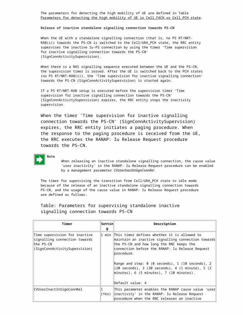
Periodic Cell/URA update is not received during the time supervision
When the periodic 'Cell/URA update wait' timer (no periodic Cell/URA update received) expires, the RRC entity initiates the RANAP: Iu Release Request procedure (cause value: 'radio connection with UE lost') towards the PS-CN, and all reserved resources for the UE are released. After this, if there is a cell update received from the UE, the UE will be unknown and the RRC connection is released by using cause value 'DSCR'.
Detecting the mobility level of UE
When the UE is Cell_DCH state, its location is known at cell level. The Handover Control detects the high mobility of UE by counting the active set changes needed for the UE.
If UE is detected as fast moving UE already in Cell_DCH state it is also used to predict the fast movement of UE in Cell_FACH and Cell_PCH state.
In Cell_FACH and Cell_PCH state the UE behaviour is also supervised by a counter, which counts the number of cell updates because of cell reselections. When the number of cell reselections has exceeded the limit defined by the management parameter ‘MaxCellReselections‘ in the time window defined by management parameter ‘CellReselectionObserving Time’ (see Table Timer for user inactivity detection in Cell_PCH state ), the UE is detected as fast moving.
When moving the UE from Cell_FACH state to PCH states or after cell reselection triggers in Cell_PCH state, this information and the information received from Handover Control is used to define the target RRC state (Cell_PCH or URA_PCH).
When the UE is in URA_PCH state RNC observes the changes of the Cell_IDs. When Cell/URA update message is received from the same cell predefined number of times consecutively, RNC interprets the UE as slow moving UE. When target PCH state is evaluated the RNC transfers UE to Cell_PCH state instead of URA_PCH state.
Table: Parameters for detecting the high mobility of UE in Cell_FACH or Cell_PCH state
Parameters Setting Description
Max cell reselections (MaxCellReselections)
3 times
The maximum allowed number of cell reselections during Cell Reselection Observing Time in Cell_FACH or Cell_PCH state before transition to URA_PCH state.
The number of cell reselections is counted in both Cell_FACH and Cell_PCH states. When the UE is in Cell_FACH state, the value of the Max cell reselections (MaxCellReselections) during Cell Reselection Observing Time (CellReselectionObservingTime) is used when deciding a target state after the MAC-c entity has sent an inactivity indication to L3.
The value ‘0’ means that the URA_PCH state is "disabled".
Range and step: 0 ... 100 times, step 1 times
Cell Reselection Observing Time (CellReselectionObservingTime)
16 min
The timer is set when the first Cell Update message because of 'cell reselection' is received while UE is in CELL_FACH or CELL_PCH state. In expiry of the timer, the counter MaxCellReselections is reset.
Range and step: 1..60, step 1 min
Transition from Cell_FACH state to Cell/URA_PCH state
Since the UE performs continuous reception of FACH in Cell_FACH state, it should be moved to the Cell_PCH state if there is not any data transmission or signalling activity for a while.
The state transition from Cell_FACH state to Cell_PCH state is performed for the following reasons:
inactivity detection in Cell_FACH state completion of Cell update/URA update procedure
Inactivity detection in Cell_FACH state
State transition to Cell/URA_PCH state because of the inactivity detection in Cell_FACH state is started when the MAC entity of the RNC indicates observed inactivity of NRT RAB(s) in uplink and downlink directions by sending the inactivity indication to the RRC entity.
PS RT RAB is inactive in common channel states (Cell_FACH, Cell/URA_PCH). State transition to Cell/URA_PCH state is allowed in the following situations:
The value of the MS activity supervision timer (MSActivitySupervision) is non-zero, indicating that Cell_PCH/URA_PCH states can be used and the UE has (inactive) PS NRT/RT-RAB(s).
The UE has only a standalone signalling connection towards the PS-CN and the initial value of the timer ‘Time supervision for inactive signalling connection’ towards the PS-CN (SignConnActivitySupervision) is non-zero, indicating that maintaining of an inactive signalling connection towards the PS-CN is allowed (and the PCH states are in use).
The UE supports the Cell/URA_PCH state.
If the above-mentioned criteria are fulfilled, the state transition from Cell_FACH state to Cell/URA_PCH state is started by the RRC entity when an inactivity indication is received from the MAC entity, and there is no RRC/RANAP procedure in progress.
Inactivity supervision is performed separately for the signalling connection to monitor signalling activity and for the PS RT/NRT-RAB(s) for data transmission activity, after the UE is switched to the PCH states.
The timers for supervising and controlling the state transition from Cell_FACH state to Cell/URA_PCH state are defined as follows:
Table: Timers for supervising and controlling the state transition from Cell_FACH state to Cell/URA_PCH state
Timer Setting Description
UL/DL activation timer (UL_DL_activation_timer) (Cell_FACH state; uplink and downlink)
2000 ms This timer is used on MAC-c to detect idle periods on data transmission for the UE in Cell_FACH state.
Range and step: 50 ... 10000 ms, step 50 ms
ExtendedULDLActivationTmr 0 (zero) This parameter defines an extended Cell_FACH state inactivity supervision time used by the RNC (instead of the normal UL_DL_Activation_Timer obtained from the RNC-DB).
Range: 0...120s, step 1 s; 0 = ‘not in use’
MS activity supervision timer (MSActivitySupervision)
29 min This timer is used in RRC states Cell_PCH and URA_PCH for supervising the inactivity of PS RT/NRT RAB(s).
If the parameter value is set to zero, state transition to Cell_PCH/URA_PCH state is not allowed. When inactivity is detected in Cell_FACH state, the UE will be switched to the idle mode.
Range and step: 0 ... 1440 min, step 1 min
Time supervision for inactive signalling connection towards the PS-CN (SignConnActivitySupervision)
1 min This timer defines whether it is allowed to maintain an inactive signalling connection towards the PS-CN, and how long the RNC keeps the connection before the RANAP: Iu Release Request procedure.
Range and step: 0 (0 seconds), 1 (10 seconds), 2 (20 seconds), 3 (30 seconds), 4 (1 minute), 5 (2 minutes), 6 (5 minutes), 7 (10 minutes).
Default value: 4
CVUserInactInSignConnRel 1 (Yes) This parameter defines whether it is allowed to use the RANAP cause value ‘user inactivity’ in the RANAP: Iu Release Request procedure when the RNC is releasing an inactive signalling connection towards the PS-CN.
If this cause value is used, the SGSN is allowed to ignore the Iu release request (that is, the SGSN may decide whether to keep the Iu connection or release it immediately when the request is received from the RNC).

Timer Setting Description
If the SGSN ignores the Iu release request, the RNC restarts the SignConnActivitySupervision. The UE is switched to the PCH state if there are no other activities (for example RT-service or signalling) in progress at this moment.
0 (No), 1 (Yes)
Completion of cell update procedure
The state transition from Cell_FACH state to Cell/URA_PCH state is done immediately (by using the RRC: Cell Update Confirm message or RRC: URA update Confirm message) after a successful Cell/URA update procedure because of cell reselection or periodic cell update if the UE was in Cell/URA_PCH before executing cell/URA update procedure. The target state after Cell/URA update procedure depends on the detection of UE mobility level (see Detecting the mobility level of UE ).