cell+phone based+wayfinding+for+the+visually+impaired
TRANSCRIPT

8/7/2019 Cell+Phone Based+Wayfinding+for+the+Visually+Impaired
http://slidepdf.com/reader/full/cellphone-basedwayfindingforthevisuallyimpaired 1/15
Cell Phone-based Waynding for the VisuallyImpaired
James Coughlan 1 , Roberto Manduchi 2 , and Huiying Shen 1
1 Smith-Kettlewell Eye Research Institute 2318 Fillmore StreetSan Francisco, CA 94115
{coughlan,hshen }@ski.org2 University of California, Santa Cruz
1156 High StreetSanta Cruz, CA 95064
Abstract. A major challenge faced by the blind and visually impairedpopulation is that of waynding – the ability of a person to nd his orher way to a given destination. We propose a new waynding aid basedon a camera cell phone, which is held by the user to nd and read aloudspecially designed machine-readable signs in the environment (labelinglocations such as offices and restrooms). Our main technical innovationis that we have designed these machine-readable signs to be detectedand located in fractions of a second on the cell phone CPU, even at adistance of several meters. A linear barcode printed on the sign is readusing novel decoding algorithms that are robust to noisy images. Theinformation read from the barcode is then read aloud using pre-recordedor synthetic speech. We have implemented a prototype system on theNokia 7610 cell phone, and preliminary experiments with blind subjectsdemonstrate the feasibility of using the system as a real-time waynding
aid.
8/7/2019 Cell+Phone Based+Wayfinding+for+the+Visually+Impaired
http://slidepdf.com/reader/full/cellphone-basedwayfindingforthevisuallyimpaired 2/15
2
1 Introduction
There are nearly 1 million legally blind persons in the United States, and up to10 million with signicant visual impairments. A major challenge faced by thispopulation is that of waynding – the ability of a person to nd his or her way toa given destination. Well-established orientation and mobility techniques usinga cane or guide dog are effective for following paths and avoiding obstacles, butare less helpful for nding specic locations or objects.
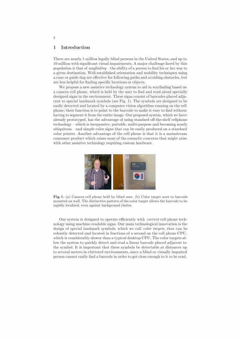
We propose a new assistive technology system to aid in waynding based ona camera cell phone, which is held by the user to nd and read aloud speciallydesigned signs in the environment. These signs consist of barcodes placed adja-cent to special landmark symbols (see Fig. 1). The symbols are designed to beeasily detected and located by a computer vision algorithm running on the cellphone; their function is to point to the barcode to make it easy to nd withouthaving to segment it from the entire image. Our proposed system, which we havealready prototyped, has the advantage of using standard off-the-shelf cellphonetechnology – which is inexpensive, portable, multi-purpose and becoming nearlyubiquitous – and simple color signs that can be easily produced on a standardcolor printer. Another advantage of the cell phone is that it is a mainstreamconsumer product which raises none of the cosmetic concerns that might arisewith other assistive technology requiring custom hardware.
Fig. 1. (a) Camera cell phone held by blind user. (b) Color target next to barcodemounted on wall. The distinctive pattern of the color target allows the barcode to berapidly localized, even against background clutter.
Our system is designed to operate efficiently with current cell phone tech-nology using machine-readable signs. Our main technological innovation is thedesign of special landmark symbols, which we call color targets , that can berobustly detected and located in fractions of a second on the cell phone CPU,which is considerably slower than a typical desktop CPU. The color targets al-low the system to quickly detect and read a linear barcode placed adjacent tothe symbol. It is important that these symbols be detectable at distances upto several meters in cluttered environments, since a blind or visually impairedperson cannot easily nd a barcode in order to get close enough to it to be read.

8/7/2019 Cell+Phone Based+Wayfinding+for+the+Visually+Impaired
http://slidepdf.com/reader/full/cellphone-basedwayfindingforthevisuallyimpaired 3/15
3
Once the system detects a color target it guides the user towards the sign byproviding appropriate audio feedback.
It is also important to be able to read the barcode from as far away aspossible (without it being unacceptably large), so that the user does not have toget too close to it. We have devised novel algorithms for reading linear barcodesphotographed by the camera cell phone under adverse – but not uncommon –conditions such as poor resolution, low light and image noise. These conditionsare all the more serious because the cell phone camera is of considerably lowerquality than a typical digital camera; low resolution, saturation and poor colordelity are particularly problematic.
We have implemented a prototype system that works with any camera cellphone running the Symbian OS. The system is set up to guide the user towardssigns using audio beeps, and reads aloud the sign information using pre-recordedspeech (which will eventually be replaced by text-to-speech). Sign informationcan either be encoded directly as ASCII text in the barcode, or can encode a
link to an information database (which is what our prototype does on a smallscale). The signs are affixed to the walls of office building corridors to label suchlocations as particular office numbers and restrooms. Preliminary experimentswith blind subjects demonstrate the feasibility of using the system as a real-timewaynding aid (see Sec. 5).
2 Related Work
A number of approaches have been explored to help blind travelers with ori-entation, navigation and waynding, most using modalities other than com-puter vision. Among the most promising include infrared signage that broad-casts information received by a hand-held receiver [6], GPS-based localization
(e.g. http://www.senderogroup.com), RFID labeling, and indoor Wi-Fi basedlocalization (based on signal strength) and database access [11]. However, eachof these approaches has signicant limitations that limit their attractiveness asstand-alone solutions. Infrared signs require costly installation and maintenance;GPS has poor resolution in urban settings and is unavailable indoors; RFIDs canonly be read at close range and would therefore be difficult to locate by blindtravelers; and Wi-Fi localization requires extensive deployment to ensure com-plete coverage, as well as a time-consuming calibration process.
Research has been undertaken on computer vision algorithms to aid in waynd-ing for such applications as navigation in traffic intersections [19] and sign read-ing [17]. The obvious advantage of computer vision is that it is designed to workwith little or no infrastructure or modication to the environment. However,none of it is yet practical for commercial use because of issues such as insuffi-cient reliability and prohibitive computational complexity (which is especiallyproblematic when using the kind of portable hardware that these applicationsrequire).
Our approach, image-based labeling, is motivated by the need for computervision algorithms that can run quickly and reliably on portable camera cell
8/7/2019 Cell+Phone Based+Wayfinding+for+the+Visually+Impaired
http://slidepdf.com/reader/full/cellphone-basedwayfindingforthevisuallyimpaired 4/15
4
phones, requiring only minor modications to the environment (i.e. posting spe-cial signs). Image-based labeling has been used extensively for product tagging(barcodes) and for robotic positioning and navigation (ducials) [4, 18, 16, 3, 14].It is important to recognize that a tag reading system must support two comple-mentary functionalities: detection and data embedding. These two functionalitiespose different challenges to the designer. Reliable detection requires unambigu-ous target appearance, whereas data embedding calls for robust spatial dataencoding mechanisms. Distinctive visual features can be used to maximize thelikelihood of successful detection. Computational speed is a critical issue for ourapplication. We argue that color targets have a clear advantage in this sensewith respect to black and white textured patterns.
Variations on the theme of barcodes have become popular for spatial in-formation encoding. Besides the typical applications of merchandise or postalparcel tagging, these systems have been demonstrated in conjunction with cam-era phones in a number of focused applications, such as linking a product or
a yer to a URL. Commercial systems of this type include the Semacode, QRcode, Shotcode and Nextcode. An important limitation of these tags is that theyneed to be seen from a close distance in order to decode their dense spatial pat-terns. Our approach addresses both requirements mentioned above by combininga highly distinctive ducial with a barcode (see Sec. 3 for details).
Direct text reading would be highly desirable, since it requires no additionalenvironment labeling. Standard OCR (optical character recognition) techniquesare effective for reading text against a blank background and at a close distance[21], but they fail in the presence of clutter [13]. Recently developed algorithmsaddress text localization in cluttered scenes [2, 9, 12, 10], but they currently re-quire more CPU power than is available in an inexpensive, portable unit: ourpreliminary tests show cell phone processing speed to be 10-20 times slower thanthat of a portable notebook computer for integer calculations (and slower still if
oating point calculations are performed). Barcodes suffer from a similar limita-tion in that they must be localized, typically by a hand-held scanner, before theycan be read. We note that our color target approach solves both the problemsof quickly localizing barcodes or text and of extracting the specic informationthat is relevant to waynding.
3 Color Targets
We have designed the color targets to solve the problem of localizing informationon signs. The targets are designed to be distinctive and difficult to confuse withtypical background clutter, and are detectable by a robust algorithm that canrun very quickly on a cell phone (i.e. up to 2 or more frames/sec. depending onresolution). Once the targets are detected, barcodes or text adjacent to them areeasily localized (see Sec. 4). A variety of work on the design and use of speciallydesigned, easily localized landmarks (i.e. ducials) has been undertaken [3, 4],but to the best of our knowledge this is the rst cell phone-based application of landmark symbols to the problem of environmental labeling.

8/7/2019 Cell+Phone Based+Wayfinding+for+the+Visually+Impaired
http://slidepdf.com/reader/full/cellphone-basedwayfindingforthevisuallyimpaired 5/15
5
We use a cascade lter design (such as that used in [20]) to rapidly detect thecolor target in clutter. The rst lter in the cascade is designed to quickly ruleout regions of the image that do not contain the target, such as homogeneousregions (e.g. blue sky or white wall without markings). Subsequent lters ruleout more and more non-target locations in the image, so that only the locationscontaining a target pass all the lter tests in the cascade (with very few falsepositives).
3.1 Color for Rapid Search
Rather than rely on generic edge-like patterns – which are numerous in almostevery image of a real scene – we select for a smaller set of edges: those at theboundaries of particular color combinations, identied by certain color gradients.Empirically we have found that red-green boundaries are comparatively rare inmost scenes compared to the incidence of general edges of all colors. A small but
signicant number of red-green boundaries are still present in non-target regions.However, we have found that the combination of three colors in a particularspatial conguration (see Fig. 2) is characterized by multiple color gradientswhich together suffice to rule out almost all false positives.
Some form of color constancy is required if color is to be a dening feature of the target under varied illumination. One solution would be to pre-process theentire image with a generic color constancy algorithm [1], but such processinggenerally makes restrictive assumptions about illumination conditions and/orrequires signicant computational resources. Fortunately, while the appearanceof individual colors varies markedly depending on illumination, color gradientstend to vary signicantly less [8]. We exploit this fact to design a cascade of ltersthat threshold certain color gradient components. The gradients are estimatedby computing differences in RGB channels among three pixels in a triangular
conguration (Fig. 2(a)). The centroid of the three pixels, ( x, y ), is swept acrossthe entire pixel lattice. Empirically, ve sequential color gradient tests suffice torule out all but a small fraction of the image pixels that do not lie on a colortarget.
The choice of gradient thresholds, and the sequence these tests appear in thecascade, were chosen empirically by taking pictures of the color target undera variety of indoor and outdoor lighting conditions: sunlight, shade, uorescentlight and tungsten (incandescent) lighting (Fig. 2(b)). Then for each color regionin each picture the mean and variance of red, green and blue channels werecalculated. Under the assumption that, for a given image, the colors in differentpatches (( R i , G i , B i ) denotes the color at point pi ) are uncorrelated, the varianceof the difference (say, of R 1 − R 2 ) is equal to the sum of the variances in each patch(the mean of R 1 − R 2 is always equal to the difference of the means in the twopatches in the same image). The ± 1σ condence interval of each difference foreach image was plotted. In practice we set T = 20 as a conservative threshold foreach lter in the cascade to handle low lighting conditions. Separate thresholdsfor each test will be investigated in future research to optimize the detection vs.false positive rate.

8/7/2019 Cell+Phone Based+Wayfinding+for+the+Visually+Impaired
http://slidepdf.com/reader/full/cellphone-basedwayfindingforthevisuallyimpaired 6/15
6
20 40 60 80 100 120 140
R1-R2
G2-G1
G2-G3
R1-R3
B3-B1
R1-R2 > T? G2-G1 > T? G2-G3 > T? R1-R3 > T? B3-B1 > T? Target Detected
No Detection
Fig. 2. Top left: Sample point locations p1 , p2 and p3 in red, green and blue regionsare dened by xed offsets relative to the center (x,y). Top right: Empirical condenceintervals of RGB channel differences between pairs of regions under different lightingconditions. Legend: brown = direct sunlight; magenta = shade; green = uorescent
light; and orange = tungsten (incandescent) lighting. Bottom: lter cascade, a sequenceof ve inequality tests based on RGB values at p 1 , p2 and p3 .
Additional post-processing is needed to rule out the few false positives thatsurvive the lter cascade. In our preliminary experiments we have implementeda grouping procedure that classies sufficiently large clusters of on-target pixelsas belonging to a single target (most false positive pixels are scattered sparselythroughout the image). Since relatively few pixels are classied as on-target inmost images, the grouping procedure adds negligible cost to the overall targetdetection algorithm. If necessary in the future we will implement additional teststo use a higher-level model to verify each candidate target (e.g. based on ttinga circle or ellipse to the edges of the hypothesized three-color region).
Fig. 3. Images with detection results drawn as white crosses superimposed on targets.
We implemented this simple prototype algorithm in C++ on a Nokia 7610 cellphone running the Symbian 7.0 OS. The camera in the phone has a maximumresolution of 1152 by 864 pixels. The algorithm detects multiple targets in afraction of a second to about half a second (depending on camera resolution).The detection is invariant to a range of scales (from about 0.5 m to as far as10 m), and accommodates signicant rotations (up to about 30 degrees in the
8/7/2019 Cell+Phone Based+Wayfinding+for+the+Visually+Impaired
http://slidepdf.com/reader/full/cellphone-basedwayfindingforthevisuallyimpaired 7/15
7
camera plane), slant and background clutter. See Fig. 3 for examples of detectionresults.
Note that the color targets need to be well illuminated to be detected, or elseimage noise will obscure the target colors. One way to overcome this limitationmight be to operate a ash with the camera, but this approach would use signif-icant amounts of battery power, would fail at medium to long range, and wouldbe annoying to other people in the environment. Another possibility might be toincrease the exposure time of the camera, but this would make the images moresusceptible to motion blur; similarly, increasing the camera gain would increasepixel noise as well as the brightness. Overall, it seems most practical to site thetargets at locations that are already well lit.
3.2 Theoretical and Empirical Bounds
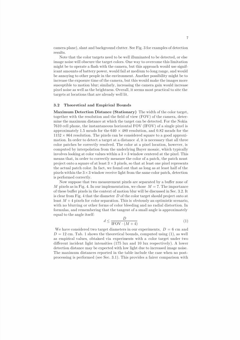
Maximum Detection Distance (Stationary) The width of the color target,together with the resolution and the eld of view (FOV) of the camera, deter-mine the maximum distance at which the target can be detected. For the Nokia7610 cell phone, the instantaneous horizontal FOV (IFOV) of a single pixel isapproximately 1.5 mrads for the 640 × 480 resolution, and 0.82 mrads for the1152 × 864 resolution. The pixels can be considered square to a good approxi-mation. In order to detect a target at a distance d, it is necessary that all threecolor patches be correctly resolved. The color at a pixel location, however, iscomputed by interpolation from the underlying Bayer mosaic, which typicallyinvolves looking at color values within a 3 × 3 window centered at the pixel. Thismeans that, in order to correctly measure the color of a patch, the patch mustproject onto a square of at least 3 × 3 pixels, so that at least one pixel representsthe actual patch color. In fact, we found out that as long as at least half of thepixels within the 3 × 3 window receive light from the same color patch, detection
is performed correctly.Now suppose that two measurement pixels are separated by a buffer zone of M pixels as in Fig. 4. In our implementation, we chose M = 7. The importanceof these buffer pixels in the context of motion blur will be discussed in Sec. 3.2. Itis clear from Fig. 4 that the diameter D of the color target should project onto atleast M + 4 pixels for color separation. This is obviously an optimistic scenario,with no blurring or other forms of color bleeding and no radial distortion. Informulas, and remembering that the tangent of a small angle is approximatelyequal to the angle itself:
d ≤D
IFOV · (M + 4)(1)
We have considered two target diameters in our experiments, D = 6 cm andD = 12 cm. Tab. 1 shows the theoretical bounds, computed using (1), as wellas empirical values, obtained via experiments with a color target under twodifferent incident light intensities (175 lux and 10 lux respectively). A lowerdetection distance may be expected with low light due to increased image noise.The maximum distances reported in the table include the case when no post-processing is performed (see Sec. 3.1). This provides a fairer comparison with

8/7/2019 Cell+Phone Based+Wayfinding+for+the+Visually+Impaired
http://slidepdf.com/reader/full/cellphone-basedwayfindingforthevisuallyimpaired 8/15
8
x x
x
Fig. 4. The layout of a 3-patch color target, with the location of the “probing” pixels.The lower two pixels are separated by a buffer of M = 7 pixels.
the model of Fig. 4, which only requires one point triplet detection. Of course,postprocessing (which is necessary to reject false positives) reduces the maximumdetection distance, since it requires that a certain number of triplets is found.The experiments were conducted while holding the cell phone still in the user’shand. Note that the experimental values, at least for the case of well lit targetand without postprocessing, do not differ too much from the theoretical bounds,which were obtained using a rather simplistic model.
D = 6 cm D = 12 cmTheor. Exp. - No PP. Exp. - PP. Theor. Exp. - No PP. Exp. - PP.
640 × 480 3.6 3.5 (3) 2.7 (2.4) 7.2 6.7 (5.7) 5.6 (4.7)1152 × 864 6.6 5.5 (4.5) 4.3 (3) 13.2 11.1 (8.5) 9.3 (6.4)Table 1. Maximum distances (in meters) for color target detection. Theoretical boundsare reported together with experimental values with and without the postprocessing(PP.) module. Values in the case of poor illumination are shown within parentheses.
Maximum Detection Distance (Panning) Searching for a color target istypically performed by pivoting the cell phone around a vertical axis (panning)while in low-res (640 × 480) mode. Due to motion, blur may and will arise,especially when the exposure time is large (low light conditions). Motion bluraffects the maximum distance at which the target can be detected. A simpletheoretical model is presented below, providing some theoretical bounds.
Motion blur occurs because, during exposure time, a pixel receives light froma larger surface patch than when the camera is stationary. We will assume forsimplicity’s sake that motion is rotational around an axis through the focal pointof the camera (this approximates the effect of a user pivoting the cell phonearound his or her wrist). If ω is the angular velocity and T is the exposure time,a pixel effectively receives light from a horizontal angle equal to IFOV + ωT .This affects color separation in two ways. Firstly, consider the vertical separationbetween the two lower patches in the color target. For the two lower probingpixels in Fig. 4 to receive light from different color patches , it is necessary that
8/7/2019 Cell+Phone Based+Wayfinding+for+the+Visually+Impaired
http://slidepdf.com/reader/full/cellphone-basedwayfindingforthevisuallyimpaired 9/15
9
the apparent image motion be less than ⌊M/ 2⌋− 13 (this formula takes the Bayercolor pattern interpolation into account). The apparent motion (in pixels) dueto panning is equal to ωT / IFOV, and therefore the largest acceptable angularvelocity is (⌊M/ 2⌋ − 1) · IFOV /T . For example, for M = 7 and T = 1 / 125 s,this corresponds to 21 .5◦ /s. The second way in which motion blur can affectthe measured color is by edge effects. This can be avoided by adding a “bufferzone” of ⌈ωT / IFOV ⌉ pixels to the probing pixels of Fig. 4. This means thatthe diameter of the target should project onto M + 2 · (2 + ⌈ωT / IFOV ⌉) pixels.Hence, the maximum distance for detection decreases with respect to the caseof Sec. 3.2.
In fact, these theoretical bounds are somewhat pessimistic, since a certainamount of motion blur does not necessarily mean that the target cannot berecognized. In order to get some more realistic gures, we ran a number of experiments, by pivoting the cell phone at different angular velocities in frontof a 12 cm target from a distance of 2 meters. Since we could neither control
nor measure exposure time, comparison with the theoretical bounds is difficult.When the color target was lit with average light intensity (88 lux), detectionwas obtained with probability larger than 0.5 at angular speeds of up to 60 ◦ /s.With lower incident light (10 lux), this value was reduced to 30 ◦ /s, presumablydue to larger exposure time.
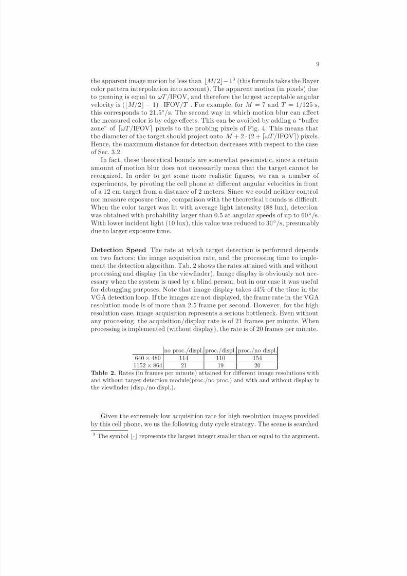
Detection Speed The rate at which target detection is performed dependson two factors: the image acquisition rate, and the processing time to imple-ment the detection algorithm. Tab. 2 shows the rates attained with and withoutprocessing and display (in the viewnder). Image display is obviously not nec-essary when the system is used by a blind person, but in our case it was usefulfor debugging purposes. Note that image display takes 44% of the time in theVGA detection loop. If the images are not displayed, the frame rate in the VGAresolution mode is of more than 2.5 frame per second. However, for the highresolution case, image acquisition represents a serious bottleneck. Even withoutany processing, the acquisition/display rate is of 21 frames per minute. Whenprocessing is implemented (without display), the rate is of 20 frames per minute.
no proc./displ. proc./displ. proc./no displ.640 × 480 114 110 154
1152 × 864 21 19 20Table 2. Rates (in frames per minute) attained for different image resolutions withand without target detection module(proc./no proc.) and with and without display inthe viewnder (disp./no displ.).
Given the extremely low acquisition rate for high resolution images providedby this cell phone, we us the following duty cycle strategy. The scene is searched
3 The symbol ⌊·⌋ represents the largest integer smaller than or equal to the argument.
8/7/2019 Cell+Phone Based+Wayfinding+for+the+Visually+Impaired
http://slidepdf.com/reader/full/cellphone-basedwayfindingforthevisuallyimpaired 10/15
10
using VGA resolution. When a target is detected over a certain number M (e.g.,M = 5) of consecutive frames, a high resolution snapshot is taken. Bar codeanalysis is then implemented over the high resolution data. The number M of frames should be large enough to allow the user to stop the panning motion,thereby stabilizing the image and reducing the risk of motion blur when readingthe bar code.
4 Barcodes
The barcode is a time-tested visual means for conveying information throughspatial patterns. The Universal Product Code (UPC) barcode represents digitsas sequences of four consecutive variable-width bars with alternating color. Morerecently, a wide variety of 2-D barcodes have been proposed (e.g., SemaCode,www.semacode.org; Datamatrix, www.tec-it.com). Some of these codes havebeen designed expressly for a camera phone (e.g., ShotCode, www.shotcode.com;ColorCode, www.colorzip.co.jp/en). The vast majority of proposed tags are in-tended for either inventory/labeling or for product promotion. In the rst case,dedicated hardware is normally used for tag reading. In the case of product pro-motion, a user is supposed to take a picture of the tag from a relatively shortdistance.
A barcode for our application should convey necessary information whilebeing easily readable from a camera phone. Detectability of the barcode, a fore-most problem for automated systems [7], is solved by means of our color targetdiscussed earlier. Once the color target has been detected, the barcode is foundwithin a “reading window” near it. The number of bits that need to be encodedin the barcode is highly variable. Only a few bits (4-5) are needed to specify acategory of locations, for example whether the tag signals an elevator, an emer-
gency exit, or a restroom. More bits are required to encode a descriptive string(e.g., the name of an office’s occupant) or a link such as a URL.For our initial experiments we used a simplied 1-D barcode. These codes
have low efficiency (in terms of bits per surface area), but this redundancy canbe exploited for increased robustness and of speed of reading. In particular, 1-Dbarcodes can be read by analyzing the brightness pattern along a line within acertain range of orientations, and multiple line readings can be used for valida-tion. The next subsection describes a simple, fast and robust algorithm for 1-Dbarcode reading that only uses xed point computation (i.e. C++ integer mathwithout any oating point computations).
4.1 Fast and Robust 1-D Barcode Reading
The barcodes used in our experiments are a simplied version of the standardUPC codes. We use only 2 bar widths, with each bar encoding 1 bit. In addition,we don’t constrain the rst bar to be of a xed (narrow) width, thereby gaining1 bit. Fixing the width of the rst bar allows UPC codes to be read by a serialscanning machine, which uses the rst bar for calibration. Instead, our system

8/7/2019 Cell+Phone Based+Wayfinding+for+the+Visually+Impaired
http://slidepdf.com/reader/full/cellphone-basedwayfindingforthevisuallyimpaired 11/15
11
learns the apparent bar widths in the image directly by the statistics of barwidths, under the assumption that there is at least one narrow and one widebar.
The two main steps of our 1-D barcode reading are: (1) Determination of eachbar’s width; (2) Determination of the correct bar width threshold for classifyingeach bar as “narrow” or “wide”. For the rst step, we have tried with twodifferent algorithms, obtaining similar results. Note that we can safely assumethat, as long as the camera is roughly horizontal, there is no need for re–orientingthe barcode, and reading can be performed along image rows. The rst algorithmidenties the maxima of the brightness derivatives along each row, and retainsonly the maxima above a certain threshold. The sign of the derivative (polarity)gives indication of whether a white or black is to the right of the maximumlocation. The second algorithm uses a version of Niblack’s algorithm for imagebinarization [15]. At each row within the reading window, we compute localbrightness mean and covariance on a 1-D moving window with size of 32 pixels.
When the variance is larger than a xed threshold (in our case, 800), the meanis used as a brightness threshold for binarization. Otherwise, the pixel is simplybinarized to 0. An example of binarization is shown in Fig. 5 (b).
20 40 60 80 100 120 140 160
20
40
60
80
100
120
140
20 40 60 80 100 120 140 160
20
40
60
80
100
120
140
20 40 60 80 100 120 140 160 180 200
20
40
60
80
100
120
20 40 60 80 100 120 140
20
40
60
80
100
120
140
Fig. 5. Illustration of stages of barcode reading algorithm. Top left (a): Original image.(Note that, in practice, smaller reading windows with size of 40 by 200 pixels are used.)Top right (b): Binarized image. Bottom left (c): detected bars, with widths quantized to“narrow” and “wide” according to chosen threshold (which is estimated independentlyfor each row). Only the rst N = 27 bars are considered. Bottom right (d): MatrixM i,j as described in the text. (In this example the barcode was decoded correctly.)
For each row within the reading window, we then compute the length of eachrun of consecutive 0 (black) and 1 (white) pixels. The main assumption hereis that the rst bar is separated from the color target by a small patch, and

8/7/2019 Cell+Phone Based+Wayfinding+for+the+Visually+Impaired
http://slidepdf.com/reader/full/cellphone-basedwayfindingforthevisuallyimpaired 12/15
12
that the colors in the target are binarized to 0. Hence, the rst (black) bar ina left–to–right scanning must be preceded by at least one white pixel. Only thewidth for at most N consecutive runs of pixels need to be computed, where N ,the number of bars in the pattern, is known in advance.
The next step consists of the estimation of the widths of the narrow bars(W n ) and of the wide bars ( W w ), whose ratio is known ( W w = 3 W n for ourpatterns). We use a simple maximum likelihood procedure for this. We denethe un–normalized negative log–likelihood of the bar ensemble given a candidatebar width W n as follows:
L(W n ) =N
i =1
min( |W (i) − W n | , |W (i) − 3W n |) (2)
where W (i) is the width of the i–th bar in the current row. The value W nthat minimizes L(W n ) represents the most likely width for the narrow bars.Accordingly, the bar width threshold is set to 0 .5(W n + W w ) = 2 W n . The searchfor the optimal width W n is performed exhaustively over a xed interval ([1,20]in our case). Since the bar widths can only take integer values, we use a stepequal to 1/3 of a pixel (which translates to a step of 1 pixel for W w ). Fig. 5 (c)shows for each row the detected bars, with widths quantized to “narrow” and“wide” according to the chosen threshold.
At this point, each row in the reading window is characterized by a binarystring (with 0 and 1 corresponding to narrow and wide bars respectively) with atmost N bits. We should expect that some (possibly more than half) of the rowsmay contain incorrect values, either because the row was partially or entirelyoutside the barcode pattern, or because of binarization and/or bar thresholding
errors. The next step consists of the determination of the “optimal” binary stringbased on a maximum voting procedure. More precisely, we consider each pair of strings (for rows i and j ) and compute the number M i,j of corresponding bitswith matching values. (This is related to the Hamming distance between the twostrings.) The string of index i with the maximum cumulative value j = i M i,jis chosen as the best representative of the string ensemble. An example of thematrix M i,j is shown in Fig. 5 (d).
This algorithm is very fast, and is applied only on the reading window, whichin our experiments had size of 40 by 200 pixels. The added computational costis negligible. The main weakness of the algorithm is that it relies entirely on acorrect brightness binarization step. Poor binarization may incorrectly join threeconsecutive bars into one (typically due to blurring) or split one bar into three(typically due to noise). As long as such phenomena are local, they are rejectedby our inter–row validation procedure. Another concern is that bar widths arequantized to an integer number of pixels. This may determine an incorrect barwidth threshold determination when the pattern is seen from a distance (andthus bars have a short apparent widths). We plan to implement a binarizationprocedure that allows for subpixel localization of bar edges.

8/7/2019 Cell+Phone Based+Wayfinding+for+the+Visually+Impaired
http://slidepdf.com/reader/full/cellphone-basedwayfindingforthevisuallyimpaired 13/15
13
5 Experiments with Blind Subjects
We have conducted three proof-of-concept experiments to demonstrate the fea-sibility of a blind person using a cell phone to obtain location information usinga color target. These experiments were performed by three blind volunteers whowere informed of the purpose of the experiments. To guide the subjects towardscolor targets using the system, we devised a simple three-pitch audio feedbackstrategy: low, medium or high tones signied the target appearing in the left,center or right part of the camera’s eld of view, respectively, and silence signiedthat no target was visible to the system. We used 640 × 480 camera resolution inthe experiments, which allowed the system to process a few frames per second.In addition, we performed the experiments with a modied color target based onfour color patches rather than three (white, green, black and red); this was donebecause we found that the low light levels which prevailed in the experimentmade it difficult to capture the blue patch in the original target. (We expect
that the results of Sec. 3.2 will be similar for the modied target, and we willinvestigate several color target pattern variants in future research.)In the rst experiment, a blind subject was seated near the wall of a confer-
ence room, and a color target was placed on another wall in one of four possiblelocations relative to the subject: left, far left, right or far right. For each trial, thecolor target location was chosen at random by the experimenter. The subject wasasked to use the cell phone target detector to identify which location the targetwas in. After a practice session, he identied the location for ten consecutivetrials without making any mistakes.
A second experiment featuring a more challenging task was conducted withanother blind subject, testing his ability to locate, walk to and touch a colortarget in an unknown location. For each trial, the experimenter placed a colortarget at a random location (at shoulder height) on the walls of an obstacle-free
conference room approximately 7 meters by 5 meters in size. Beginning in thecenter of the room, the second blind subject used the color target detector tond the color target, walk towards it and touch it. In 20 trials (after a trainingsession), it took him anywhere from 13 to 33 seconds to touch the target -signicantly faster than if he had searched the perimeter of the room for thetarget by feel alone (which would have taken on the order of minutes ratherthan tens of seconds). In 19 of the 20 trials he touched only the target, while inone trial he rst touched the wall several inches away before reaching the target.
The third experiment was designed to test the ability of a blind subject to ndlocations of interest in an office corridor using the color target system. The goalwas for him to nd four locations along either wall of a straight corridor (about 30meters long) using the cell phone system; he was advised that the labels did notcorrespond to the actual building layout, so that his familiarity with the buildingwould not affect the outcome of the experiment. A color target with 5-bit barcode was affixed at waist height near each of the four locations in the corridor.The bar codes encoded four separate numbers which were associated with fourpre-recorded sounds (”elevator,” ”restroom,” ”room 417” and ”staircase”). Thesubject was instructed to walk along the corridor to scan for all four labels.
8/7/2019 Cell+Phone Based+Wayfinding+for+the+Visually+Impaired
http://slidepdf.com/reader/full/cellphone-basedwayfindingforthevisuallyimpaired 14/15
14
When the camera was close enough to the color target, the bar code next to itwas read and the appropriate recording was played back. After a training session,the labels were moved to new locations and the subject was able to nd all fourof them in about two minutes. No false positives or false bar code readings wereencountered during the experiment.
While these experiments are preliminary, they show that blind subjects areable to use a simple cell phone interface to locate signs – at a range of distances– and that they are capable of orienting the camera properly and moving itsmoothly and slowly enough to prevent interference from motion blur. Theseresults provide direct evidence of the feasibility of our proposed system.
6 Conclusion
We have demonstrated a camera cell phone-based waynding system that allowsa visually impaired user to nd and read signs marked with color targets andbarcodes. A key challenge of the system is the limited computational power of thecell phone, which is about 10-20 times slower than a typical notebook computer.Our solution is to place a distinctive color target pattern on the sign, which maybe rapidly detected (using integer arithmetic) even in cluttered scenes. Thisswiftly guides the system to an adjacent barcode, which we read using a novelalgorithm that is robust to poor resolution and lighting. Preliminary experimentswith blind subjects conrm the feasibility of the system.
A priority for future work is to detect and read signs at greater distances.This task will become easier as higher resolution cell phone cameras becomeavailable. In addition, we will investigate variations on the color target designand improvements that will allow color target detection algorithms to reliablydetect color targets with smaller apparent size (i.e. at a greater distance). We
will also explore ways of increasing the information density of barcodes, such asthe use of 2-D barcodes. Finally, we will test the system with more blind andlow vision subjects to determine the most effective user interface, which maycombine the use of vibratory signals, audio tones and synthesized speech.
7 Acknowledgments
We would like to thank Alessandro Temil for valuable assistance with SymbianC++ programming. J.C. and H.S. were supported by the National Instituteon Disability and Rehabilitation Research (grant no. H133G030080), the NSF(grant no. IIS0415310) and the National Eye Institute (grant no. EY015187-01A2).
References
1. D.H. Brainard and W.T. Freeman. “Bayesian Color Constancy.” J. Opt. Soc. Amer.-A, 14:1393–1411, July 1997.

8/7/2019 Cell+Phone Based+Wayfinding+for+the+Visually+Impaired
http://slidepdf.com/reader/full/cellphone-basedwayfindingforthevisuallyimpaired 15/15
15
2. X. Chen and A. L. Yuille. “Detecting and Reading Text in Natural Scenes.” CVPR2004.
3. Y. Cho and U. Neumann. ”Multi-ring color ducial systems for scalable ducialtracking augmented reality”. In: Proc. of IEEE VRAIS. 1998.
4. D. Claus and A.W. Fitzgibbon. (2004) ”Reliable Fiducial Detection in NaturalScenes”, in Proc. ECCV, 2004.
5. J. Coughlan, R. Manduchi, M. Mutsuzaki and H. Shen. “Rapid and Robust Algo-rithms for Detecting Colour Targets.” 10th Congress of the International ColourAssociation, AIC Colour ’05, pp. 959 - 962. Granada, Spain. May 2005.
6. W. Crandall, B. Bentzen, L. Myers and J. Brabyn. New orientation and accessibilityoption for persons with visual impairment: transportation applications for remoteinfrared audible signage. Clinical and Experimental Optometry 2001 May, 84(3):120-131.
7. M. Fiala. ”ARTag, A Fiducial Marker System using Digital Techniques.” IEEE Proc.CVPR. San Diego, June 2005.
8. Funt, B.V., and Finlayson, G., ’Color Constant Color Indexing,’ IEEE Transactionson Pattern Analysis and Machine Intelligence, 17 (5), 522-529, May 1995.
9. J. Gao and J. Yang. “An Adaptive Algorithm for Text Detection from NaturalScenes.” CVPR 2001.
10. A.K. Jain and B. Tu. “Automatic Text Localization in Images and Video Frames.”Pattern Recognition. 31(12), pp 2055-2076. 1998.
11. A.M. Ladd, K.E. Bekris, A.P. Rudys, D.S. Wallach and L.E. Kavraki. ”On the fea-sibility of using wireless ethernet for indoor localization”, IEEE Trans. On Roboticsand Automation, 20(3):555-9, June 2004.
12. H. Li, D. Doermann and O. Kia. Automatic text detection and tracking in digitalvideos. IEEE Transactions on Image Processing, 9(1):147–156, January 2000.
13. J. Liang, D. Doermann and H. Li. ”Camera-based analysis of text and documents:a survey”, International Journal on Document Analysis and Recognition, 7:84-104,2005.
14. L. Naimark and E. Foxlin. (2002) Circular data matrix ducial system and robustimage processing for a wearable vision-inertial self-tracker. In: ISMAR.
15. M. Rohs, “Real–World Interaction with a Camera–Phone”, Second InternationalSymposium on Ubiquitous Computing Systems (UCS 2004), Tokyo, Japan.16. D. Scharstein and A. Briggs. (2001) ”Real-time recognition of self-similar land-
marks”. Image and Vision Computing 19, 763-772.17. P. Silapachote, J. Weinman, A. Hanson, R. Weiss and M. A. Mattar. “Automatic
Sign Detection and Recognition in Natural Scenes.” IEEE Workshop on ComputerVision Applications for the Visually Impaired (CVAVI ’05), in conjunction withCVPR ’05. San Diego, CA. June 20, 2005.
18. A. State et al. (1996) ”Superior augmented reality registration by integrating land-mark tracking and magnetic tracking”. In: SIGGRAPH429-438.
19. M.S. Uddin and T. Shioyama. “Bipolarity- and Projective Invariant-Based Zebra-Crossing Detection for the Visually Impaired.” IEEE Workshop on Computer VisionApplications for the Visually Impaired (CVAVI ’05), in conjunction with CVPR ’05.San Diego, CA. June 20, 2005.
20. P. Viola and M. Jones. ”Rapid Object Detection using a Boosted Cascade of SimpleFeatures.” CVPR 2001. Kauai, Hawaii. December 2001.21. A. Zandifar, P.R. Duraiswami, A. Chahine and L.S. Davis. ”A Video Based Inter-
face to Textual Information for the Visually Impaired”, Fourth IEEE InternationalConference on Multimodal Interfaces (ICMI’02).