cement and concrete research - home |...
TRANSCRIPT
Cement and Concrete Research 43 (2013) 34–50
Contents lists available at SciVerse ScienceDirect
Cement and Concrete Research
j ourna l homepage: ht tp : / /ees .e lsev ie r .com/CEMCON/defau l t .asp
Effect of microstructure on load-carrying and energy-dissipation capacities of UHPC
Jonathan J. Buck, David L. McDowell, Min Zhou ⁎The George W. Woodruff School of Mechanical Engineering, The School of Materials Science and Engineering, Georgia Institute of Technology, Atlanta, GA 30332-0405, USA
⁎ Corresponding author. Tel.: +1 404 894 3294.E-mail address: [email protected] (M. Zhou).
0008-8846/$ – see front matter © 2012 Elsevier Ltd. Allhttp://dx.doi.org/10.1016/j.cemconres.2012.10.006
a b s t r a c t
a r t i c l e i n f oArticle history:Received 9 May 2012Accepted 11 October 2012Available online xxxx
Keywords:Ultra-high-performance concrete (E)Microstructure (D)Energy dissipation (C)Load-carrying capacity (C)
The load-carrying and energy dissipation capacities of ultra-high performance concrete (UHPC) under dynamicloading are evaluated in relation tomicrostructure composition at strain rates on the order of 105 s−1 and pressuresof up to 10 GPa. Analysis focuses on deformation and failure mechanisms at themesostructural level. A cohesive fi-nite element framework that allows explicit account of constituent phases, interfaces, and fracture is used. Threemodes of energy dissipation are tracked, i.e., inelastic deformation, distributed cracking, and interfacial friction. Sim-ulations are carried out over a range of volume fractions of constituent phases. Results show that (1) volume frac-tions of the constituents have more influence on the energy-dissipation than load-carrying capacity, (2) inelasticdeformation is the source of over 70% of the energy dissipation, and (3) the presence of porosity changes the roleof fibers in the dissipation process. Microstructure–behavior relations are established to facilitate materials designfor target-specific applications.
© 2012 Elsevier Ltd. All rights reserved.
1. Introduction
Ultra-high-performance concrete (UHPC) is a relatively new and ad-vanced buildingmaterial that provides several advantages over conven-tional concrete. Benefits include significantly enhanced ductility andenergy-absorption capabilities [1–4] that lead to compressive strengthsin excess of 150 MPa and flexural strengths of over 200 times those ofconventional concrete [5]. These attributes are possible, because UHPChas several unique characteristics that set it apart from more conven-tional forms of concrete, including finer quartz aggregate, a lowerwater-to-cement ratio, and the presence of superplasticizers and fineductilemetal or polymer fibers. These properties lendUHPC to structur-al applications in which resistance to blast and impact is of paramountimportance. Designing UHPC structures that are resilient to such ex-treme loading events requires that the material has high strength, thecapacity to dissipate much of the imparted energy, and the capabilityto attenuate the stress caused by the loading. However, it is not clearhow the characteristics of UHPC at the microstructural level determinethese attributes. In particular, the effects of the constituent volumefractions on load-carrying and energy-dissipation capacities underhigh-rate loading have not been systematically quantified using realis-tic micromechanical models. Establishing these relationships is impor-tant, as the relations can be used to tailor UHPC structures to mitigatespecific threats.
The large number of design variables at the microstructural level,such as volume fractions of constituent phases, microstructuremorphol-ogy, constituent size scales, constituent behaviors, and interfacial bond-ing strength, pose a challenge in exploring microstructure-property/
rights reserved.
response relations. Developing comprehensive structure–property rela-tions, however, requires that these variables and their interactions be an-alyzed. The influence of microstructure can be investigated usingexperimental methods and/or numerical techniques. The use of experi-mental methods is expensive and lengthy for such complex systems, be-cause the number of experiments needed for such a task can quicklygrow beyond allowable financial and time constraints. Experiments arelimited to samples that are physically available and cannot be used to an-alyzematerials that do not yet exist. Additionally, deformation processesinvolved in the dynamic response of UHPC, including distributedmicrocracking, friction, and granular flow, are inherently coupled phe-nomena that are difficult to fully capture separately using experimentalmethods. Nonetheless, these processes and their interactions must bequantified to tailor materials for specific applications.
Numerical simulations offer a useful means for establishingmicrostructure–performance relations. Much of the published literatureinvolving numerical simulations of concrete implements homogenizedphenomenological constitutive relations at the macrostructural scale.For example, Mroz and Angelillo developed a rate-dependent modelfor concrete [6]. Themodel makes use of a damage surface with an asso-ciated flow rule to account for stiffness degradation. Voyiadjis andTaqieddin developed an elasto-plastic damagemodel for concrete mate-rials that uses the crack density to quantify the degradation in the elastic-ity tensor [7]. The model is capable of reproducing the post-failuresoftening behavior that is representative of concrete. A similar modelwas also developed by Fanella and Krajcinovic [8]. Grassl and Jirásek de-veloped a damage-plasticity model that incorporates the effective stressto account for plasticity and the plastic strain to account for damage [9].The model was applied on the structural scale to analyze a reinforcedconcrete column and successfully captured the qualitative nature of ex-perimental load–displacement curves. A number of other hydrocode
35J.J. Buck et al. / Cement and Concrete Research 43 (2013) 34–50
models are available for simulating the nonlinear dynamic responses ofconcrete structures [10].
Mesoscale simulations that fully account for the heterogeneous na-ture of concrete can help explain the micro-scale processes that giverise to the observed structural response on the macro-scale. Park, Xia,and Zhou [11] conducted numerical simulations at the mesoscale usinga fully dynamic finite element model to systematically study the effectof aggregate volume fraction on the strength and energy dissipation ca-pacity of plain concrete. Their micromechanical model explicitly ac-counts for the two-phase structure of cementitious matrix and quartzaggregate of plain concrete. The simulations concern strain rates on theorder of 104 s−1 and hydrostatic pressures up to 1.5 GPa. The resultsshow that an aggregate volume fraction of 42% leads to a 15% improve-ment in energy-dissipation capacity and a 30% enhancement in strengthas compared to plain mortar. Aragao et al. [12] conducted simulationsusing a cohesive finite element model to analyze fracture and failure inconcrete at the microstructural level in which the two-phase structureof cementitiousmatrix and quartz aggregate is explicitlymodeled. Cohe-sive traction and fracture energy parameters are calibrated in a mannerthat allows the model to accurately represent experimental data fromquasi-static tensile tests. Xu, Hao, and Li [13] performed a similar studyinvolving a mesoscale numerical model of fiber-reinforced concretethat provide explicit account of the matrix, aggregate, and fiber phases.The study considered the effects of aggregate and fiber size distribution,as well as fiber volume fraction, on the dynamic compressive strength offiber-reinforced concrete. The results show that fiber volume fractions inthe range of 0.6% to 1.8% do not appreciably change the compressive dy-namic inflation factor, i.e., at a given strain rate, dynamic compressivestrength is independent of fiber content. Bolander and Lim [14] devel-oped a latticemodelwith discrete representations offibers and the inter-face between fibers and the cementitious matrix to assess the effects offiber distribution on the durability mechanics of fiber-reinforcedconcrete.
Lammi et al. [15] investigated the dynamic fracture and dissipationbehavior of concrete at several levels of hierarchy of microstructure/mesostructure using a cohesive finite element model that accounts forcrack formation and frictional dissipation at crack faces. The nominalstrain rate considered is on the order of 103 s−1. Quartz aggregate andporosity are explicitly modeled, along with the interface between thephases. The volume fractions of quartz and porosity considered are inthe ranges of 0–40% and 0–5%, respectively. The results show that theconcrete with 40% aggregate by volume has a load-carrying capacitythat is up to 12.2% higher than that of pure matrix without aggregate.A porosity level of 5% decreases the load-carrying capacity by up to10.9%. Porosity is also found to have themost significant effect on energydissipation by enhancing plastic deformation.
Ellis et al. [16] carried out numerical simulations of 3D microstruc-tures with explicit resolution of porosity and steel fibers within a ce-mentitious matrix. The interface between fibers and matrix was alsoexplicitly modeled. At strain rates of 5×10²–103 s−1, increasing thefiber volume fraction from 0% to 2% is found to increase theload-carrying capacity by up to 19%. The energy dissipation is found todepend most significantly on the fiber volume fraction. In contrast,
Table 1Summary of mesoscale numerical simulations of UHPC reported in the literature.
Researchers Vfa(%) Vf
p(%)
Park, Xia, and Zhou [0, 10, 15, 22, 32, 42] –
Aragao, et al. N/A1 –
Xu, Hao, and Li 40% –
Bolander and Lim N/A1 –
Lammi, McDowell, and Zhou [10, 20, 30, 40] [0, 2.5, 5]Ellis, McDowell, and Zhou – [1,5,10]
a N/A indicates that the value was not explicitly stated in the work.
porosity has only aminor influence on energy dissipation. The foregoingmesoscale simulations are summarized in Table 1.
A number of issues have yet to be addressed. First and foremost, therehas not been a thorough and systematic characterization of the dynamicbehavior of UHPC. In particular, the material performance in relation tothe volume fractions of constituents has not been investigated over a suf-ficientlywide range. Numerical simulations are needed that consider theessential deformation mechanisms that occur at the microstructurallevel, including fracture, friction, and inelastic granular flow [17]. Thereis a lack of understanding on how these microstructural-level mecha-nisms affect macroscopic responses of the overall composites. Many ofthe analytical models developed in the open literature to characterizethese relationships require an excessive number of material parameters,some of which have no basis in the physical processes underlying thematerial behavior [18]. Consequently, these models are often applicableonly to relatively narrow ranges of compositions and loading conditionsspecific to the experiments on which the phenomenological constitutiverelations are based [19]. Additionally, there have been no studies on theattenuation of stress waves as they traverse heterogeneous UHPCmicro-structures. There have also been no studies on the relative contributionsof mechanisms for energy dissipation as a stress wave propagatesthrough the structure, which has been identified by a panel of expertsas a fundamental research need in the field of fiber-reinforced cement[20]. Also, the constituents in UHPC are known to undergo phase trans-formations under conditions with high temperatures and high pressuresresulting from loading of sufficient magnitudes. In particular, at pres-sures above 2.35 GPa, the quartz aggregate phase in concrete undergoesa phase transformation from α-quartz to coesite, which involves avolume change of 8.82%. The effects of such phase transformations ofconstituents in UHPC on the overall mechanical response of thematerialhave not been quantified. This paper focuses on the behavior withoutphase transformations. The effect of the pressure-induced α-quartz-to-coesite phase transformation of the quartz aggregate is analyzed in[21].
In the analysis conducted here, a micromechanical cohesive finite el-ementmodel (CFEM) similar to that used by Lammi et al. [15] is adoptedto allow explicit resolution of the constituents in the concrete micro-structure, including the cementitious matrix, aggregate, fibers, andvoids. Themodel also allows explicit account of crack formation and fric-tional interaction between crack surfaces that come into contact undercompression. This approach enables the contributions of different dissi-pation mechanisms (bulk inelasticity, fracture/crack formation, and in-terfacial friction) to be tracked and quantified. Additionally, thisapproach captures the interaction and coupling of the dissipation pro-cesses at the microstructural level. The composition of the microstruc-ture is systematically varied over a wide range to delineate the effectsof each material constituent. Simulations are carried out at strain rateson the order of 104 s−1. The analyses also focus on the correlation be-tween volume fractions of constituent phases andmacroscopic responsein terms of load carried, stress attenuation, crack formation, and energydissipated. The results are used to develop microstructure–performancerelationmaps that canbe used to identify desiredmaterial design param-eters for specific application conditions.
Vff(%) _ε s−1
� �Interfaces (yes/no)?
– 104 N– 0.01 Y[0.6, 1.2, 1.8] 0.45–427 NN/Aa N/A1 Y– 5×10³ Y[0, 2, 4] 5×10³ Y
0
2.5
5
10
20
30
400
2.55
7.510
(%)pfV
(%)afV
(%)ffV
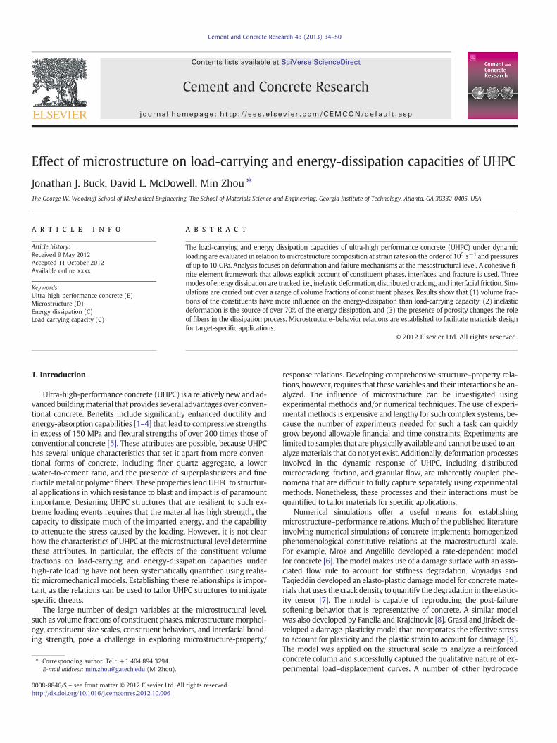
Fig. 1. Microstructure design space with combinations of constituent volume fractionsanalyzed.
Table 2Diameters of quartz, porosity, and fibers used for all mi-crostructures in the numerical simulations.
Phase Diameter (μm)
Quartz 600Porosity 100Fiber 200
36 J.J. Buck et al. / Cement and Concrete Research 43 (2013) 34–50
2. Microstructure instantiation
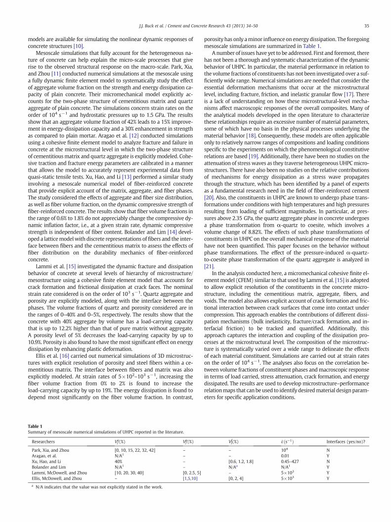
One of the goals of this work is to thoroughly characterize the dy-namic behavior of UHPC over a wide range of constituent volume frac-tions. This necessitates a large number ofmicrostructural instantiations.A total of 60 unique microstructures are generated with idealized 2Dmorphologies, reflecting all combinations of the aggregate, void, andfiber contents. The parametric range of constituent volume fractions isshown in Fig. 1. Five samplemicrostructures are shown in Fig. 2 to illus-trate the variation in the volume fractions of the constituents. The mi-crostructures analyzed are generated in a manner similar to that inLammi et al. [15]. The purpose of this study is to quantify theload-carrying and energy-dissipation capacities of UHPC as functionsof the volume fractions of phases, rather than phase size or size distribu-tion. The effect ofmorphology of the constituents is beyond the scope ofthe currentwork and is reserved for future study. Consequently, each ofthe phases has a fixed size with no deviation, as shown in Table 2. Thefibers, idealized as ellipses in 2D, are given a constant ellipticity ratioof 5:1. The microstructure samples are 5 by 20 mm in size.
Fig. 2. Microstructures with 10% aggregate, 2.5% porosity, and (a) 0% fib
3. Constitutive relations
3.1. Cementitious matrix
Cementitious materials are both pressure-sensitive and rate-sensitive, so the constitutive relation used must be able to capture bothaspects of the behavior. In this study, the Drucker–Prager model isused for the cementitious matrix [22]. The Drucker–Prager relation as-sumes the yield condition
F ¼ t−p tan βð Þ−d ≤ 0; ð1Þ
where
t ¼ 12q 1þ 1
K− 1− 1
K
� �rq
� �3� �: ð2Þ
In the above equations, p is the hydrostatic pressure, β is the internalfriction angle in themeridional stress plane, d is the yield stress of thema-terial under pure shear, q is the von Mises equivalent stress, given byq ¼ ffiffiffiffiffiffiffiffiffiffiffi
32S : S
p, K is the ratio between the yield stress in triaxial tension
and the yield stress in triaxial compression, and r is the third invariantof the deviatoric stress, given by r ¼ ffiffiffiffiffiffiffiffiffiffiffiffiffiffiffi
92S⋅S : S3
p. In the preceding
expressions, S is the deviatoric stress tensor. Parameter K allows fortension-compression asymmetry on any arbitrary π-plane. To ensure aconvex yield surface, the value of K is restricted to the range0.778≤K≤1.0. SettingK=1removes thedependence on the third invari-ant of the deviatoric stress, and Eq. (1) reduces to the classical Drucker–
ers, (b) 2.5% fibers, (c) 5% fibers, (d) 7.5% fibers, and (e) 10% fibers.
Table 4Parameters used in Johnson–Cook model for reinforcing steelfibers.
Density (g/cm3) 7.8Young's modulus E (GPa) 203Poisson's ratio ν 0.28A (Mpa) 792B (Mpa) 510n 0.26C 0.014Troom (K) 300Tmelt (K) 1793m 1.03_ε0 (s−1) 1Specific heat (J/kg-K) 477
37J.J. Buck et al. / Cement and Concrete Research 43 (2013) 34–50
Prager yield criterion [23]. Furthermore,whenK=1andβ=0, Eq. (1) re-duces to the von Mises yield criterion.
Because cementitious paste exhibits dilatation and is a non-associative material, the yield function F does not serve as the plasticflow potential. Instead, a scalar flow potential G is chosen such that
G ¼ t−p tan ψð Þ; ð3Þ
where ψ is the dilation angle. After yielding, a material with non-associated flow has the rate of plastic deformation tensor
Dpl ¼_�ε pl
c∂G∂σ ; ð4Þ
where _�ε pl is the equivalent plastic strain rate, defined by
_�ε pl ¼ffiffiffiffiffiffiffiffiffiffiffiffiffiffiffiffiffiffiffiffiffi23Dpl : Dpl
r; ð5Þ
and
c ¼ 1−13tanψ: ð6Þ
The values used for the Drucker–Prager constitutive relation inthis study are provided in Table 3 [11].
3.2. Quartz aggregate
The quartz aggregate is given rate-independent linear elastic prop-erties. The quartz aggregate is assigned an elastic modulus of 97 GPaand a Poisson's ratio of 0.08 [15]. The brittle nature of quartz suggeststhat it will fail in shear or tension. However, the presence of cohesive el-ements accounts for this mode of failure.
3.3. Steel fibers
The Johnson–Cook model is used to describe the behavior of thesteel fibers. This model allows the rate-dependent hardening behaviorof steel to be accounted for. The Johnson–Cook constitutive relationcan be expressed as
�σ �εp; ; _εp; T� � ¼ Aþ B�εn
� �1þ Clog
_εp
_ε0
� �� �1− T−Ttr
Tm−Ttr
� �m� �: ð7Þ
Here, A, B, C, andm arematerial parameters that are calibrated usingexperimental data [24]. The first expression on the right hand side ac-counts for strain hardening, the second expression accounts forstrain-rate hardening, and the third expression accounts for thermalsoftening. Model parameters are listed in Table 4. The introduction ofreinforcing steel fibers also requires the appropriate calibration of cohe-sive bonding between the fibers and the cement matrix. The peak trac-tion and fracture energy of the fiber-cement interface are in line withvalues obtained from experimental data for fiber-reinforced cement[25,26].
Table 3Parameters used in Drucker–Prager constitutive relation.
Density (g/cm3) 2.4Elastic modulus (GPa) 22.9Poisson's ratio 0.2Quasi-static compressive strength (MPa) 40Friction angle β (degrees) 28Dilation angle ψ (degrees) 20K 0.8
3.4. Interfaces
Cohesive elements are specified between all bulk elements bound-aries with the exception of elements in the fibers, which are assumedto undergo no fracture. The cohesive elements allow for damage initia-tion and development. The use of a cohesive crack zone for modelingfracture in concrete materials has a long and well-established history,dating back to the 1970s with the work by Hillerborg, Modeer, andPetersson [27]. The use of zero-thickness cohesive elements wasestablished in 1989 by Gens, Carol, and Alonso [28]. A bilinear traction–separation law is adopted to govern the behavior of the cohesive ele-ments [29]. The use of a bilinear traction–separation law to model frac-ture in concrete materials was first formulated by Petersson [30] in1981 and has seen extensive use in the time since [31].
The linear-elastic part of the traction–separation law relates thetraction vector t to the element stiffness K and the separation uresulting from the traction vector t. This relationship is given by
t ¼ Ku: ð8Þ
The above equation can be expressed in matrix form to indicatecoupling between the normal and shear components of the traction–separation relationship, i.e.,
tntstt
0@
1A ¼
Knn Kns KntKns Kss KstKnt Kst Ktt
24
35 un
usut
0@
1A: ð9Þ
Full coupling between normal and shear components in the traction–separation response is represented by the off-diagonal terms. For thepurposes of this work, an uncoupled relation is chosen, i.e.,
tntstt
0@
1A ¼
Knn 0 00 Kss 00 0 Ktt
24
35 un
usut
0@
1A: ð10Þ
Although the linear-elastic part of the response has no couplingbetween shear and normal components, damage initiation and evolu-tion have a mixed-mode form. Damage initiation follows the quadrat-ic interaction relationship shown in Eq. (11), where tn is the normalstress in a cohesive element, ts is the shear stress, and tn
0 and ts0 are
the critical values of tn and ts, respectively, which represent the cohe-sive strength. In this paper, both ts
0 and tt0 are assumed to have the
same value. Because it is not physically meaningful for compressivetractions to contribute to damage initiation, only non-negative (ten-sile) normal tractions are considered in the damage initiation rule.This is indicated by the presence of the Macaulay brackets aroundtn. Damage is initiated when
tnh it0n
� �2þ tsh i
t0s
� �2þ tt
t0t
� �2¼ 1: ð11Þ
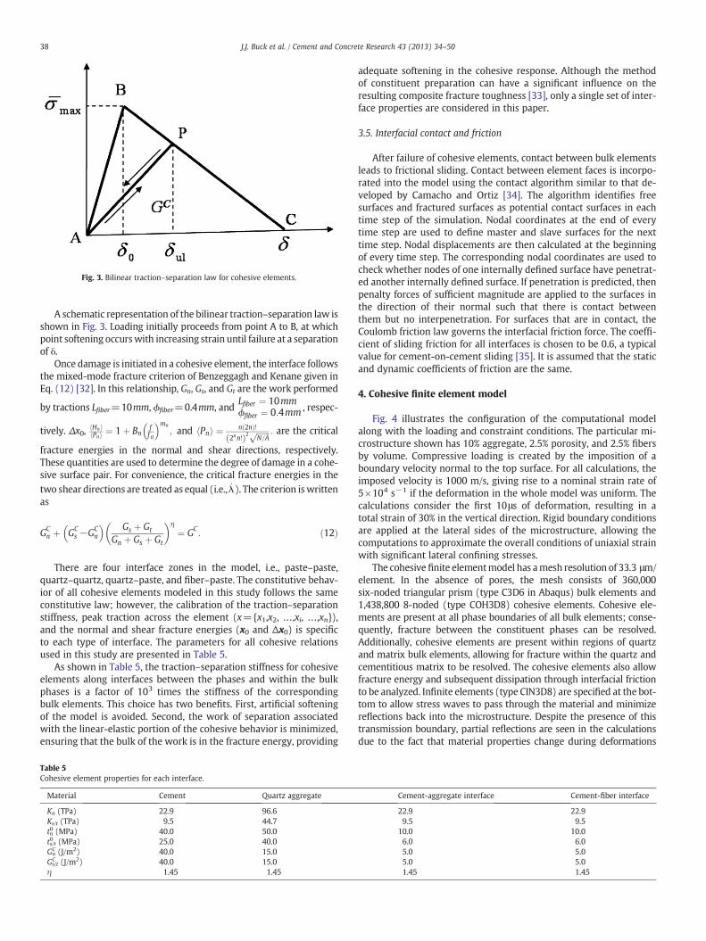
Fig. 3. Bilinear traction–separation law for cohesive elements.
38 J.J. Buck et al. / Cement and Concrete Research 43 (2013) 34–50
A schematic representation of the bilinear traction–separation law isshown in Fig. 3. Loading initially proceeds from point A to B, at whichpoint softening occurswith increasing strain until failure at a separationof δ.
Once damage is initiated in a cohesive element, the interface followsthe mixed-mode fracture criterion of Benzeggagh and Kenane given inEq. (12) [32]. In this relationship, Gn, Gs, and Gt are the work performed
by tractions Lfiber=10mm, ϕfiber=0.4mm, andLfiber ¼ 10mmϕfiber ¼ 0:4mm , respec-
tively. Δx0,Hnh iPnh i ¼ 1þ Bn
ff O
mn
; and Pnh i ¼ n 2nð Þ!2nn!ð Þ2 ffiffiffiffiffiffiffi
N=Ap : are the critical
fracture energies in the normal and shear directions, respectively.These quantities are used to determine the degree of damage in a cohe-sive surface pair. For convenience, the critical fracture energies in thetwo shear directions are treated as equal (i.e., _λ). The criterion iswrittenas
GCn þ GC
s −GCn
Gs þ Gt
Gn þ Gs þ Gt
� �η¼ GC
: ð12Þ
There are four interface zones in the model, i.e., paste–paste,quartz–quartz, quartz–paste, and fiber–paste. The constitutive behav-ior of all cohesive elements modeled in this study follows the sameconstitutive law; however, the calibration of the traction–separationstiffness, peak traction across the element (x={x1,x2, …,xi, …,xn}),and the normal and shear fracture energies (x0 and Δx0) is specificto each type of interface. The parameters for all cohesive relationsused in this study are presented in Table 5.
As shown in Table 5, the traction–separation stiffness for cohesiveelements along interfaces between the phases and within the bulkphases is a factor of 103 times the stiffness of the correspondingbulk elements. This choice has two benefits. First, artificial softeningof the model is avoided. Second, the work of separation associatedwith the linear-elastic portion of the cohesive behavior is minimized,ensuring that the bulk of the work is in the fracture energy, providing
Table 5Cohesive element properties for each interface.
Material Cement Quartz aggregate
Kn (TPa) 22.9 96.6Ks/t (TPa) 9.5 44.7tn0 (MPa) 40.0 50.0ts/t0 (MPa) 25.0 40.0GnC (J/m2) 40.0 15.0
Gs/tC (J/m2) 40.0 15.0
η 1.45 1.45
adequate softening in the cohesive response. Although the methodof constituent preparation can have a significant influence on theresulting composite fracture toughness [33], only a single set of inter-face properties are considered in this paper.
3.5. Interfacial contact and friction
After failure of cohesive elements, contact between bulk elementsleads to frictional sliding. Contact between element faces is incorpo-rated into the model using the contact algorithm similar to that de-veloped by Camacho and Ortiz [34]. The algorithm identifies freesurfaces and fractured surfaces as potential contact surfaces in eachtime step of the simulation. Nodal coordinates at the end of everytime step are used to define master and slave surfaces for the nexttime step. Nodal displacements are then calculated at the beginningof every time step. The corresponding nodal coordinates are used tocheck whether nodes of one internally defined surface have penetrat-ed another internally defined surface. If penetration is predicted, thenpenalty forces of sufficient magnitude are applied to the surfaces inthe direction of their normal such that there is contact betweenthem but no interpenetration. For surfaces that are in contact, theCoulomb friction law governs the interfacial friction force. The coeffi-cient of sliding friction for all interfaces is chosen to be 0.6, a typicalvalue for cement-on-cement sliding [35]. It is assumed that the staticand dynamic coefficients of friction are the same.
4. Cohesive finite element model
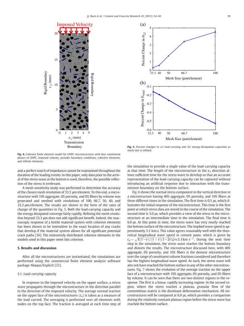
Fig. 4 illustrates the configuration of the computational modelalong with the loading and constraint conditions. The particular mi-crostructure shown has 10% aggregate, 2.5% porosity, and 2.5% fibersby volume. Compressive loading is created by the imposition of aboundary velocity normal to the top surface. For all calculations, theimposed velocity is 1000 m/s, giving rise to a nominal strain rate of5×104 s−1 if the deformation in the whole model was uniform. Thecalculations consider the first 10μs of deformation, resulting in atotal strain of 30% in the vertical direction. Rigid boundary conditionsare applied at the lateral sides of the microstructure, allowing thecomputations to approximate the overall conditions of uniaxial strainwith significant lateral confining stresses.
The cohesive finite elementmodel has amesh resolution of 33.3 μm/element. In the absence of pores, the mesh consists of 360,000six-noded triangular prism (type C3D6 in Abaqus) bulk elements and1,438,800 8-noded (type COH3D8) cohesive elements. Cohesive ele-ments are present at all phase boundaries of all bulk elements; conse-quently, fracture between the constituent phases can be resolved.Additionally, cohesive elements are present within regions of quartzand matrix bulk elements, allowing for fracture within the quartz andcementitious matrix to be resolved. The cohesive elements also allowfracture energy and subsequent dissipation through interfacial frictionto be analyzed. Infinite elements (type CIN3D8) are specified at the bot-tom to allow stress waves to pass through the material and minimizereflections back into the microstructure. Despite the presence of thistransmission boundary, partial reflections are seen in the calculationsdue to the fact that material properties change during deformations
Cement-aggregate interface Cement-fiber interface
22.9 22.99.5 9.5
10.0 10.06.0 6.05.0 5.05.0 5.01.45 1.45
Rigid B
oundaryRig
id B
ound
ary
Transmission Boundary
x1 (mm)0 1 2 3 4 5
x2
(mm
)
20
15
10
5
0
Imposed Velocity
Fig. 4. Cohesive finite element model for UHPC microstructures with four constituentphases of UHPC, imposed velocity, periodic boundary conditions, cohesive elements,and infinite elements.
(a)
(b)
Perc
ent C
hang
e in
Eto
tal
Perc
ent C
hang
e in
σ22
33.3 50 66.7 100
Mesh Size (μm/element)
33.3 50 66.7 100
Mesh Size (μm/element)
5
4
3
2
1
0
-0.1
-0.2
-0.3
-0.4
-0.5
-0.640
40
Fig. 5. Percent changes in (a) load-carrying and (b) energy-dissipation capacities asmesh size is refined.
39J.J. Buck et al. / Cement and Concrete Research 43 (2013) 34–50
and a perfectmatch of impedance cannot bemaintained throughout theduration of the loading events. In this paper, only data prior to the arriv-al of the stress wave at the bottom is used, therefore, the possible reflec-tion of the stress is irrelevant.
A mesh sensitivity study was performed to determine the accuracyof the chosenmesh resolution of 33.3 μm/element. To this end, amicro-structure with 10% aggregate, 0% porosity, and 0% fibers by volumewasgenerated and meshed with resolutions of 100, 66.7, 50, 40, and33.3 μm/element. The results are shown in the form of the rates ofchange of the quantities in Fig. 5. Both the load-carrying capacity andthe energy dissipated converge fairly rapidly. Refining themesh resolu-tion beyond 33.3 μm does not add significant benefit. Indeed, the mac-roscopic response of a brittle material system with cohesive elementshas been shown to be insensitive to the exact location of any cracksthat develop if the material system allows for all significant potentialcrack paths [36]. The extensively distributed cohesive elements in themodels used in this paper meet this criterion.
5. Results and discussion
After all the microstructures are instantiated, the simulations areperformed using the commercial finite element analysis softwarepackage Abaqus/Explicit [22].
5.1. Load-carrying capacity
In response to the imposed velocity on the upper surface, a stresswave propagates through the microstructure in the direction parallelto the direction of the imposed velocity. The average normal tractionon the upper face of the microstructures (tn) is taken as a measure ofthe load carried. The averaging is performed over all elements withnodes on the top face. The traction is averaged at each time step of
the simulation to provide a single value of the load-carrying capacityat that time. The length of the microstructure in the x2 direction al-lows sufficient time for the stress wave to develop so that an accuraterepresentation of the load-carrying capacity can be captured withoutintroducing an artificial response due to interaction with the trans-mission boundary on the bottom surface.
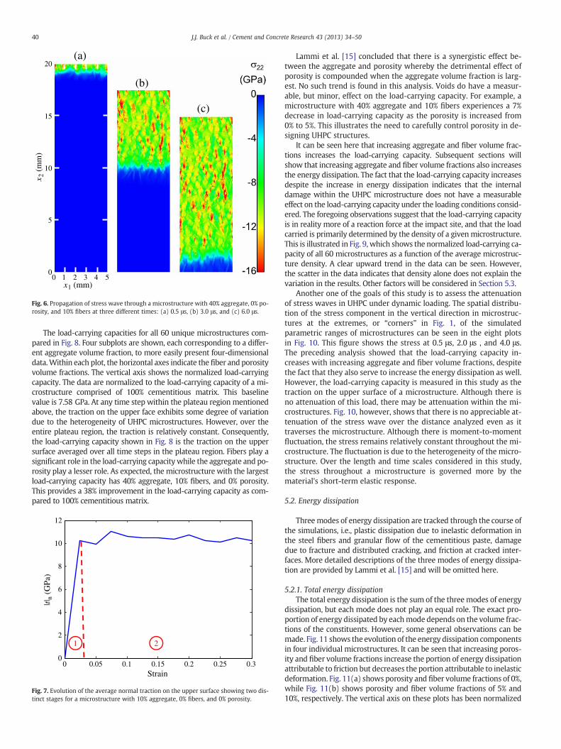
Fig. 6 shows the normal stress component in the vertical direction ina microstructure having 40% aggregate, 0% porosity, and 10% fibers atthree different times in the simulation. The first time is 0.5 μs, which il-lustrates the initial response of the microstructure. This time is the firstpoint atwhich stress data are stored in the course of the simulation. Thesecond time is 3.0 μs, which provides a view of the stress in the micro-structure at an intermediate time in the simulation. The final time is6.0 μs. At this point in time, the stress wave has very nearly reachedthe bottom surface of themicrostructure. The impliedwave speed is ap-proximately 3.3 km/s. This value agrees reasonably well with the theo-retical longitudinal wave speed in cement paste, which is given bycd ¼ ffiffiffiffiffiffiffiffiffiffiffiffiffiffiffiffiffiffiffiffiffiffiffiffiffiffiffiffiffiffiffiffiffiffiffiffiffiffiffiffiffiffiffiffiffiffiffiffiffiffiffiffiffiffi
E 1−νð Þ= 1þ νð Þ 1−2νð Þρp≈3:3km⋅s−1. During the next time
step in the simulation, the stress wave reaches the bottom boundaryand distorts the results. The microstructure discussed here, with 40%aggregate, 0% porosity, and 10% fibers is the densest microstructureover the range of constituent volume fractions considered and thereforehas the highest longitudinal wave speed. As such, the stress wave willalso not have reached the bottom surface in any of the othermicrostruc-tures. Fig. 7 shows the evolution of the average traction on the upperface of a microstructure with 10% aggregate, 0% porosity, and 0% fibersby volume. It can be seen that there are two distinct regions in the re-sponse. The first is a linear, rapidly increasing regime. In the second re-gion, where the stress reaches a plateau, granular flow of thecementitious matrix is the dominant deformation mechanism. All mi-crostructures will be compared at 6.0 μs, which provides a comparisonduring the relatively constant plateau region before the stress wave hasreached the bottom surface.
x1 (mm)0 1 2 3 4 5
x 2(m
m)
20
15
10
5
0
(a)
(b)
(c)
Fig. 6. Propagation of stress wave through a microstructure with 40% aggregate, 0% po-rosity, and 10% fibers at three different times: (a) 0.5 μs, (b) 3.0 μs, and (c) 6.0 μs.
40 J.J. Buck et al. / Cement and Concrete Research 43 (2013) 34–50
The load-carrying capacities for all 60 unique microstructures com-pared in Fig. 8. Four subplots are shown, each corresponding to a differ-ent aggregate volume fraction, to more easily present four-dimensionaldata.Within each plot, the horizontal axes indicate the fiber and porosityvolume fractions. The vertical axis shows the normalized load-carryingcapacity. The data are normalized to the load-carrying capacity of a mi-crostructure comprised of 100% cementitious matrix. This baselinevalue is 7.58 GPa. At any time step within the plateau region mentionedabove, the traction on the upper face exhibits some degree of variationdue to the heterogeneity of UHPC microstructures. However, over theentire plateau region, the traction is relatively constant. Consequently,the load-carrying capacity shown in Fig. 8 is the traction on the uppersurface averaged over all time steps in the plateau region. Fibers play asignificant role in the load-carrying capacity while the aggregate and po-rosity play a lesser role. As expected, the microstructure with the largestload-carrying capacity has 40% aggregate, 10% fibers, and 0% porosity.This provides a 38% improvement in the load-carrying capacity as com-pared to 100% cementitious matrix.
0 0.05 0.1 0.15 0.2 0.25 0.30
2
4
6
8
10
12
Strain
|t|n
(GPa
)
1 2
Fig. 7. Evolution of the average normal traction on the upper surface showing two dis-tinct stages for a microstructure with 10% aggregate, 0% fibers, and 0% porosity.
Lammi et al. [15] concluded that there is a synergistic effect be-tween the aggregate and porosity whereby the detrimental effect ofporosity is compounded when the aggregate volume fraction is larg-est. No such trend is found in this analysis. Voids do have a measur-able, but minor, effect on the load-carrying capacity. For example, amicrostructure with 40% aggregate and 10% fibers experiences a 7%decrease in load-carrying capacity as the porosity is increased from0% to 5%. This illustrates the need to carefully control porosity in de-signing UHPC structures.
It can be seen here that increasing aggregate and fiber volume frac-tions increases the load-carrying capacity. Subsequent sections willshow that increasing aggregate and fiber volume fractions also increasesthe energy dissipation. The fact that the load-carrying capacity increasesdespite the increase in energy dissipation indicates that the internaldamage within the UHPC microstructure does not have a measurableeffect on the load-carrying capacity under the loading conditions consid-ered. The foregoing observations suggest that the load-carrying capacityis in reality more of a reaction force at the impact site, and that the loadcarried is primarily determined by the density of a givenmicrostructure.This is illustrated in Fig. 9, which shows the normalized load-carrying ca-pacity of all 60 microstructures as a function of the average microstruc-ture density. A clear upward trend in the data can be seen. However,the scatter in the data indicates that density alone does not explain thevariation in the results. Other factors will be considered in Section 5.3.
Another one of the goals of this study is to assess the attenuationof stress waves in UHPC under dynamic loading. The spatial distribu-tion of the stress component in the vertical direction in microstruc-tures at the extremes, or “corners” in Fig. 1, of the simulatedparametric ranges of microstructures can be seen in the eight plotsin Fig. 10. This figure shows the stress at 0.5 μs, 2.0 μs , and 4.0 μs.The preceding analysis showed that the load-carrying capacity in-creases with increasing aggregate and fiber volume fractions, despitethe fact that they also serve to increase the energy dissipation as well.However, the load-carrying capacity is measured in this study as thetraction on the upper surface of a microstructure. Although there isno attenuation of this load, there may be attenuation within the mi-crostructures. Fig. 10, however, shows that there is no appreciable at-tenuation of the stress wave over the distance analyzed even as ittraverses the microstructure. Although there is moment-to-momentfluctuation, the stress remains relatively constant throughout the mi-crostructure. The fluctuation is due to the heterogeneity of the micro-structure. Over the length and time scales considered in this study,the stress throughout a microstructure is governed more by thematerial's short-term elastic response.
5.2. Energy dissipation
Threemodes of energy dissipation are tracked through the course ofthe simulations, i.e., plastic dissipation due to inelastic deformation inthe steel fibers and granular flow of the cementitious paste, damagedue to fracture and distributed cracking, and friction at cracked inter-faces. More detailed descriptions of the three modes of energy dissipa-tion are provided by Lammi et al. [15] and will be omitted here.
5.2.1. Total energy dissipationThe total energy dissipation is the sum of the threemodes of energy
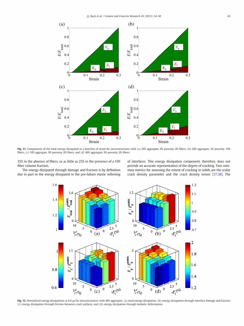
dissipation, but each mode does not play an equal role. The exact pro-portion of energy dissipated by eachmode depends on the volume frac-tions of the constituents. However, some general observations can bemade. Fig. 11 shows the evolution of the energy dissipation componentsin four individual microstructures. It can be seen that increasing poros-ity and fiber volume fractions increase the portion of energy dissipationattributable to friction but decreases the portion attributable to inelasticdeformation. Fig. 11(a) shows porosity and fiber volume fractions of 0%,while Fig. 11(b) shows porosity and fiber volume fractions of 5% and10%, respectively. The vertical axis on these plots has been normalized
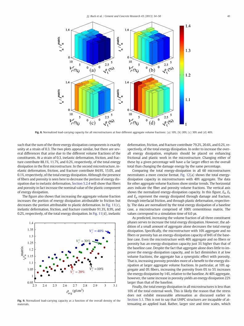
Fig. 8. Normalized load-carrying capacity for all microstructures at four different aggregate volume fractions: (a) 10%, (b) 20%, (c) 30% and (d) 40%.
41J.J. Buck et al. / Cement and Concrete Research 43 (2013) 34–50
such that the sumof the three energy dissipation components is exactlyunity at a strain of 0.3. The two plots appear similar, but there are sev-eral differences that arise due to the different volume fractions of theconstituents. At a strain of 0.3, inelastic deformation, friction, and frac-ture contribute 88.1%, 11.7%, and 0.2%, respectively, of the total energydissipation in the first microstructure. In the secondmicrostructure, in-elastic deformation, friction, and fracture contribute 84.9%, 15.0%, and0.1%, respectively, of the total energy dissipation. Although the presenceof fibers and porosity is seen here to decrease the portion of energy dis-sipation due to inelastic deformation, Section 5.2.4 will show that fibersand porosity in fact increase the nominal value of the plastic componentof energy dissipation.
The figure also shows that increasing the aggregate volume fractionincreases the portion of energy dissipation attributable to friction butdecreases the portion attributable to plastic deformation. In Fig. 11(c),inelastic deformation, friction, and fracture contribute 91.3%, 8.9%, and0.2%, respectively, of the total energy dissipation. In Fig. 11(d), inelastic
2.3 2.4 2.5 2.6 2.7 2.8 2.9 3 3.10.95
1
1.05
1.1
1.15
1.2
1.25
1.3
1.35
1.4
ρavg
(g/cm3)
mat
rix
40%afV =
30%afV =
20%afV =
10%afV =
t n/t n
Fig. 9. Normalized load-carrying capacity as a function of the overall density of thematerials.
deformation, friction, and fracture contribute 79.2%, 20.6%, and 0.2%, re-spectively, of the total energy dissipation. In order to increase the over-all energy dissipation, emphasis should be placed on enhancingfrictional and plastic work in the microstructure. Changing either ofthese by a given percentage will have a far larger effect on the overalltotal than changing the damage energy by the same percentage.
Comparing the total energy-dissipation in all 60 microstructuresnecessitates a more concise format. Fig. 12(a) shows the total energy-dissipation capacity in microstructures with 40% aggregate. The datafor other aggregate volume fractions show similar trends. The horizontalaxes indicate the fiber and porosity volume fractions. The vertical axisshows the normalized energy-dissipation capacity. In this figure, Ed, Ef,and Ep represent the energy dissipated through damage and fracture,through interfacial friction, and through plastic deformation, respective-ly. The data are normalized by the total energy dissipation of a baselinecase, a microstructure comprised of 100% cementitious matrix. Thevalues correspond to a simulation time of 6.0 μs.
As predicted, increasing the volume fraction of all three constituentphases serves to increase the total energy dissipation. However, the ad-dition of a small amount of aggregate alone decreases the total energydissipation. Specifically, the microstructure with 10% aggregate and nofibers or porosity has an energy-dissipation capacity of 84% of the base-line case. Even the microstructure with 40% aggregate and no fibers orporosity has an energy-dissipation capacity just 3% higher than that ofthe baseline case. Despite the fact that aggregate alone does little to im-prove the energy-dissipation capacity, and in fact diminishes it at lowvolume fractions, the aggregate has a synergistic effect with porosity.That is, increasing porosity providesmore of a benefit to the energy dis-sipation at larger aggregate volume fractions. In particular, at 10% ag-gregate and 0% fibers, increasing the porosity from 0% to 5% increasesthe energy dissipation by 14%, relative to the baseline. At 40% aggregate,however, the same increase in porosity yields an energy dissipation 22%larger than that of the baseline.
Finally, the total energy dissipation in all microstructures is less than10% of the total external work. This is likely the reason that the stressdoes not exhibit measurable attenuation as discussed earlier inSection 5.1. This is not to say that UHPC structures are incapable of at-tenuating an applied load. Rather, larger size and time scales, which
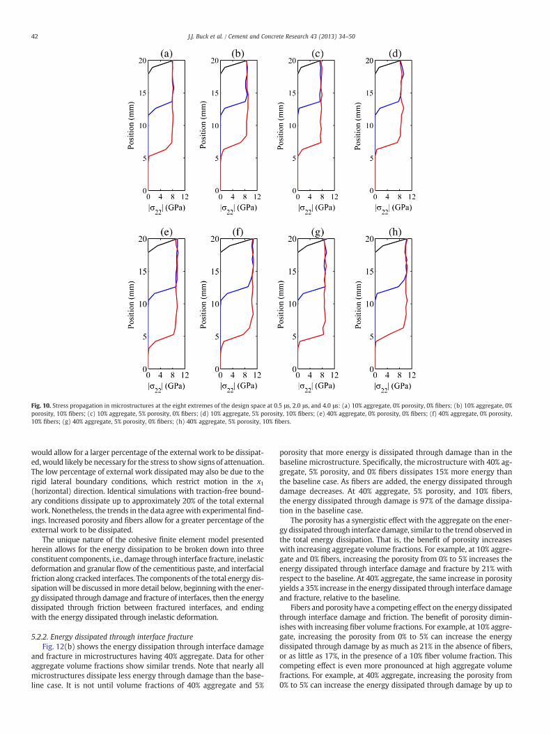
Fig. 10. Stress propagation in microstructures at the eight extremes of the design space at 0.5 μs, 2.0 μs, and 4.0 μs: (a) 10% aggregate, 0% porosity, 0% fibers; (b) 10% aggregate, 0%porosity, 10% fibers; (c) 10% aggregate, 5% porosity, 0% fibers; (d) 10% aggregate, 5% porosity, 10% fibers; (e) 40% aggregate, 0% porosity, 0% fibers; (f) 40% aggregate, 0% porosity,10% fibers; (g) 40% aggregate, 5% porosity, 0% fibers; (h) 40% aggregate, 5% porosity, 10% fibers.
42 J.J. Buck et al. / Cement and Concrete Research 43 (2013) 34–50
would allow for a larger percentage of the external work to be dissipat-ed, would likely be necessary for the stress to show signs of attenuation.The low percentage of external work dissipated may also be due to therigid lateral boundary conditions, which restrict motion in the x1(horizontal) direction. Identical simulations with traction-free bound-ary conditions dissipate up to approximately 20% of the total externalwork. Nonetheless, the trends in the data agreewith experimental find-ings. Increased porosity and fibers allow for a greater percentage of theexternal work to be dissipated.
The unique nature of the cohesive finite element model presentedherein allows for the energy dissipation to be broken down into threeconstituent components, i.e., damage through interface fracture, inelasticdeformation and granular flow of the cementitious paste, and interfacialfriction along cracked interfaces. The components of the total energy dis-sipationwill be discussed inmore detail below, beginningwith the ener-gy dissipated through damage and fracture of interfaces, then the energydissipated through friction between fractured interfaces, and endingwith the energy dissipated through inelastic deformation.
5.2.2. Energy dissipated through interface fractureFig. 12(b) shows the energy dissipation through interface damage
and fracture in microstructures having 40% aggregate. Data for otheraggregate volume fractions show similar trends. Note that nearly allmicrostructures dissipate less energy through damage than the base-line case. It is not until volume fractions of 40% aggregate and 5%
porosity that more energy is dissipated through damage than in thebaseline microstructure. Specifically, the microstructure with 40% ag-gregate, 5% porosity, and 0% fibers dissipates 15% more energy thanthe baseline case. As fibers are added, the energy dissipated throughdamage decreases. At 40% aggregate, 5% porosity, and 10% fibers,the energy dissipated through damage is 97% of the damage dissipa-tion in the baseline case.
The porosity has a synergistic effect with the aggregate on the ener-gy dissipated through interface damage, similar to the trend observed inthe total energy dissipation. That is, the benefit of porosity increaseswith increasing aggregate volume fractions. For example, at 10% aggre-gate and 0% fibers, increasing the porosity from 0% to 5% increases theenergy dissipated through interface damage and fracture by 21% withrespect to the baseline. At 40% aggregate, the same increase in porosityyields a 35% increase in the energy dissipated through interface damageand fracture, relative to the baseline.
Fibers and porosity have a competing effect on the energy dissipatedthrough interface damage and friction. The benefit of porosity dimin-ishes with increasing fiber volume fractions. For example, at 10% aggre-gate, increasing the porosity from 0% to 5% can increase the energydissipated through damage by as much as 21% in the absence of fibers,or as little as 17%, in the presence of a 10% fiber volume fraction. Thiscompeting effect is even more pronounced at high aggregate volumefractions. For example, at 40% aggregate, increasing the porosity from0% to 5% can increase the energy dissipated through damage by up to
(a) (b)
Ep
EfEd
Ep
EfEd
(c) (d)
Ep
EfEd
Ep
EfEd
Fig. 11. Components of the total energy dissipated as a function of strain for microstructures with (a) 20% aggregate, 0% porosity, 0% fibers, (b) 20% aggregate, 5% porosity, 10%fibers, (c) 10% aggregate, 0% porosity, 0% fibers, and (d) 40% aggregate, 0% porosity, 0% fibers.
43J.J. Buck et al. / Cement and Concrete Research 43 (2013) 34–50
35% in the absence of fibers, or as little as 25% in the presence of a 10%fiber volume fraction.
The energy dissipated through damage and fracture is by definitiondue in part to the energy dissipated in the pre-failure elastic softening
Fig. 12. Normalized energy dissipations at 6.0 μs for microstructures with 40% aggregate: (a)(c) energy dissipation through friction between crack surfaces, and (d) energy dissipation
of interfaces. This energy dissipation component, therefore, does notprovide an accurate representation of the degree of cracking. Two com-mon metrics for assessing the extent of cracking in solids are the scalarcrack density parameter and the crack density tensor [37,38]. The
total energy dissipation, (b) energy dissipation through interface damage and fracturethrough inelastic deformation.
44 J.J. Buck et al. / Cement and Concrete Research 43 (2013) 34–50
two-dimensional scalar crack densityDA is given byDA ¼ 1A
XNk¼1
lk2, where
A is the 2D area of averaging, lk is the half-length of the kth crack, andN isthe total number of cracks. More useful than the scalar parameter is thecrack density tensor, which provides information about the degree of an-isotropy of cracking in a solid. The components of the crack density ten-
sor are given by Dij ¼ 1A
Xnk¼1
lk2nk
i nkj where nk is the unit vector normal to
the kth crack. Provided the directional distribution of damage is ade-quately represented by a second rank tensor, the relationship betweenthe scalar crack density parameter and the tensor is simply DA=tr(D).The significance of the crack density tensor is that it provides insightinto both the extent of cracking and the degree to which it is anisotropic,which can influence the material's effective elastic properties if thecracking has a preferred orientation. For purely vertical cracking, the cor-responding crackdensity tensor only has onenon-zero component in the(1,1) position. For purely horizontal cracking, the only non-zero compo-nent of the crack density tensor is in the (2,2) position, for example.
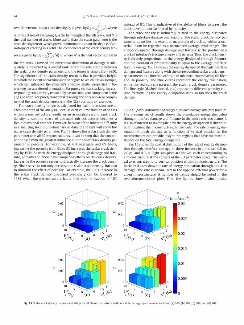
The crack density tensor is calculated for each microstructure ateach time step of the analysis. Because each volume fraction of phaseswithin a microstructure results in an associated second rank crackdensity tensor, the space of damaged microstructures becomes afive-dimensional data set. However, because of the inherent difficultyin visualizing such multi-dimensional data, the results will show thescalar crack density parameter. Fig. 13 shows the scalar crack densityparameter φ in all 60 microstructures. It can be seen that the constit-uent phase with the greatest influence on the scalar crack density pa-rameter is porosity. For example, at 40% aggregate and 0% fibers,increasing the porosity from 0% to 5% increases the scalar crack den-sity by 193%. As with the energy dissipated through damage and frac-ture, porosity and fibers have competing effects on the crack density.Increasing the porosity serves to drastically increase the crack densi-ty. Fibers serve to not only decrease the scalar crack density, but alsoto diminish the effect of porosity. For example, the 193% increase inthe scalar crack density discussed previously can be lowered to158% when the microstructure has a fiber volume fraction of 10%
Fig. 13. Scalar crack density parameter at 6.0 μs for all 60 microstructures with fou
instead of 0%. This is indicative of the ability of fibers to arrest thecrack development facilitated by porosity.
The crack density is intimately related to the energy dissipatedthrough interface damage and fracture. The scalar crack density pa-rameter quantifies the extent or magnitude of cracking within a ma-terial. It can be regarded as a normalized average crack length. Theenergy dissipated through damage and fracture is the product of acracked interface's fracture energy and its area. Thus, the crack densi-ty is directly proportional to the energy dissipated through fracture,and the constant of proportionality is equal to the average interfacefracture energy. Fig. 14 shows the energy dissipated through interfacedamage and fracture along with the corresponding scalar crack densi-ty parameter as a function of strain in microstructures having 0% fiberand 0% porosity. The blue curves represent the energy dissipation,while the red curves represent the scalar crack density parameter.The line style (dashed, dotted, etc.) represents different porosity vol-ume fractions. As the energy dissipation rises, so too does the crackdensity.
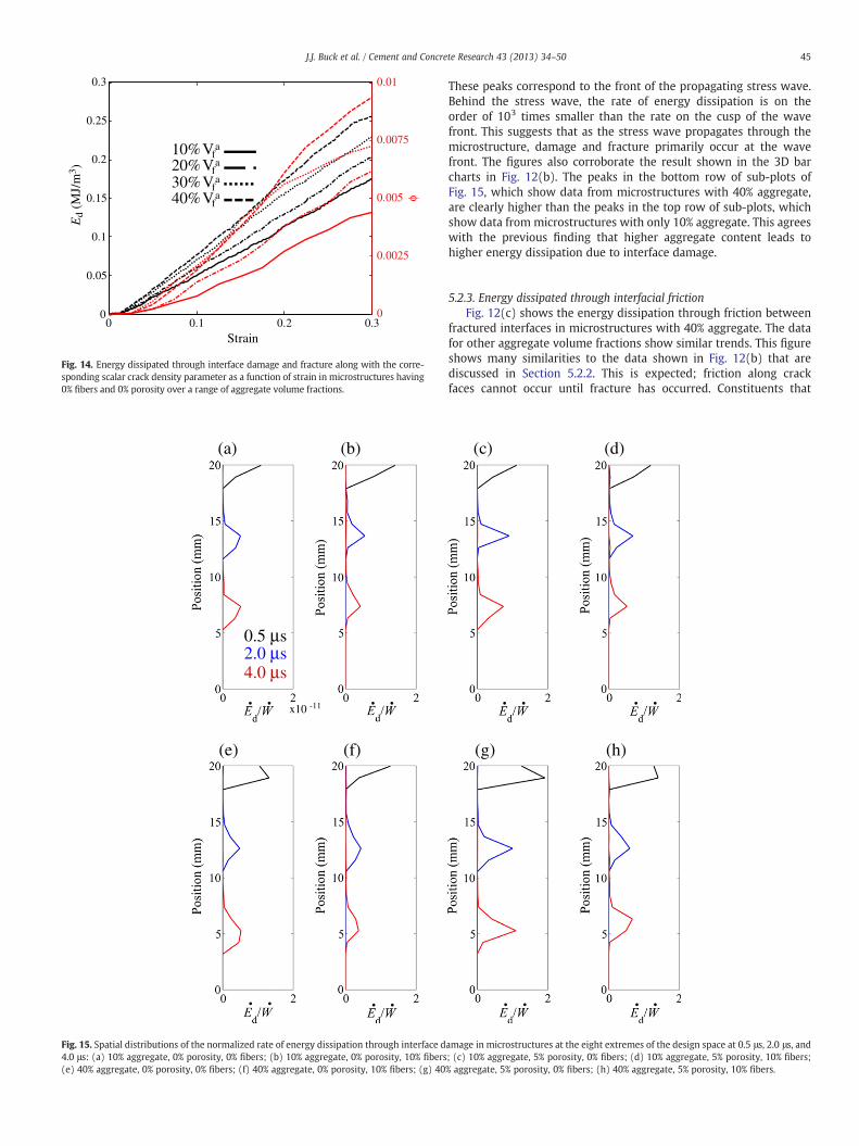
5.2.2.1. Spatial distribution of energy dissipated through interface fracture.The previous set of results shows the cumulative energy dissipatedthrough interface damage and fracture in the entire microstructure. Itis also of interest to investigate how the energy dissipation is distribut-ed throughout the microstructure. In particular, the rate of energy dis-sipation through damage as a function of vertical position in themicrostructure can provide insight into regions that have the most in-fluence on the total energy dissipation.
Fig. 15 shows the spatial distribution of the rate of energy dissipa-tion through interface damage at three instants in time, i.e., 0.5 μs,2.0 μs, and 4.0 μs. Eight sub-plots are shown, each corresponding toa microstructure at the corners of the 3D parameter space. The verti-cal axes correspond to vertical position within a microstructure. Thehorizontal axes show the rate of energy dissipation through interfacedamage. The rate is normalized to the applied external power for agiven microstructure. A number of trends should be noted in thetwo aforementioned plots. First, the figures show distinct peaks.
r different aggregate volume fractions: (a) 10%, (b) 20%, (c) 30%, and (d) 40%.
0 0.1 0.20
0.05
0.1
0.15
0.2
0.25
0.3
Strain
Ed
(MJ/
m3 )
0.0025
0.005
0.0075
0.01
10%Vfa
20%Vfa
30%Vfa
40%Vfa
0.30
Fig. 14. Energy dissipated through interface damage and fracture along with the corre-sponding scalar crack density parameter as a function of strain in microstructures having0% fibers and 0% porosity over a range of aggregate volume fractions.
(a) (b)
(e) (f)
. .
. .
. .
. .
0.5 μs 2.0 μs 4.0 μs
x10 -11
Fig. 15. Spatial distributions of the normalized rate of energy dissipation through interface d4.0 μs: (a) 10% aggregate, 0% porosity, 0% fibers; (b) 10% aggregate, 0% porosity, 10% fibers(e) 40% aggregate, 0% porosity, 0% fibers; (f) 40% aggregate, 0% porosity, 10% fibers; (g) 40
45J.J. Buck et al. / Cement and Concrete Research 43 (2013) 34–50
These peaks correspond to the front of the propagating stress wave.Behind the stress wave, the rate of energy dissipation is on theorder of 103 times smaller than the rate on the cusp of the wavefront. This suggests that as the stress wave propagates through themicrostructure, damage and fracture primarily occur at the wavefront. The figures also corroborate the result shown in the 3D barcharts in Fig. 12(b). The peaks in the bottom row of sub-plots ofFig. 15, which show data from microstructures with 40% aggregate,are clearly higher than the peaks in the top row of sub-plots, whichshow data from microstructures with only 10% aggregate. This agreeswith the previous finding that higher aggregate content leads tohigher energy dissipation due to interface damage.
5.2.3. Energy dissipated through interfacial frictionFig. 12(c) shows the energy dissipation through friction between
fractured interfaces in microstructures with 40% aggregate. The datafor other aggregate volume fractions show similar trends. This figureshows many similarities to the data shown in Fig. 12(b) that arediscussed in Section 5.2.2. This is expected; friction along crackfaces cannot occur until fracture has occurred. Constituents that
(c) (d)
(g) (h)
. .
. .
. .
. .
amage in microstructures at the eight extremes of the design space at 0.5 μs, 2.0 μs, and; (c) 10% aggregate, 5% porosity, 0% fibers; (d) 10% aggregate, 5% porosity, 10% fibers;% aggregate, 5% porosity, 0% fibers; (h) 40% aggregate, 5% porosity, 10% fibers.
(a) (b) pε(c)
2 mm
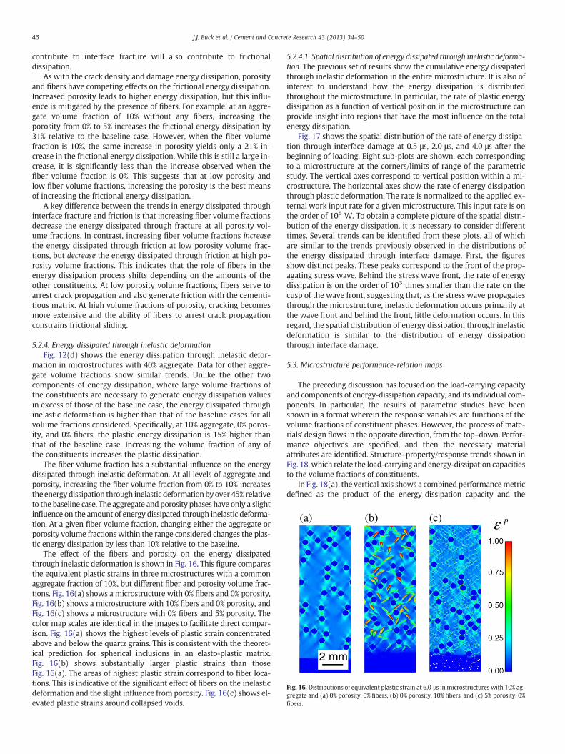
Fig. 16. Distributions of equivalent plastic strain at 6.0 μs inmicrostructures with 10% ag-gregate and (a) 0% porosity, 0% fibers, (b) 0% porosity, 10% fibers, and (c) 5% porosity, 0%fibers.
46 J.J. Buck et al. / Cement and Concrete Research 43 (2013) 34–50
contribute to interface fracture will also contribute to frictionaldissipation.
As with the crack density and damage energy dissipation, porosityand fibers have competing effects on the frictional energy dissipation.Increased porosity leads to higher energy dissipation, but this influ-ence is mitigated by the presence of fibers. For example, at an aggre-gate volume fraction of 10% without any fibers, increasing theporosity from 0% to 5% increases the frictional energy dissipation by31% relative to the baseline case. However, when the fiber volumefraction is 10%, the same increase in porosity yields only a 21% in-crease in the frictional energy dissipation. While this is still a large in-crease, it is significantly less than the increase observed when thefiber volume fraction is 0%. This suggests that at low porosity andlow fiber volume fractions, increasing the porosity is the best meansof increasing the frictional energy dissipation.
A key difference between the trends in energy dissipated throughinterface fracture and friction is that increasing fiber volume fractionsdecrease the energy dissipated through fracture at all porosity vol-ume fractions. In contrast, increasing fiber volume fractions increasethe energy dissipated through friction at low porosity volume frac-tions, but decrease the energy dissipated through friction at high po-rosity volume fractions. This indicates that the role of fibers in theenergy dissipation process shifts depending on the amounts of theother constituents. At low porosity volume fractions, fibers serve toarrest crack propagation and also generate friction with the cementi-tious matrix. At high volume fractions of porosity, cracking becomesmore extensive and the ability of fibers to arrest crack propagationconstrains frictional sliding.
5.2.4. Energy dissipated through inelastic deformationFig. 12(d) shows the energy dissipation through inelastic defor-
mation in microstructures with 40% aggregate. Data for other aggre-gate volume fractions show similar trends. Unlike the other twocomponents of energy dissipation, where large volume fractions ofthe constituents are necessary to generate energy dissipation valuesin excess of those of the baseline case, the energy dissipated throughinelastic deformation is higher than that of the baseline cases for allvolume fractions considered. Specifically, at 10% aggregate, 0% poros-ity, and 0% fibers, the plastic energy dissipation is 15% higher thanthat of the baseline case. Increasing the volume fraction of any ofthe constituents increases the plastic dissipation.
The fiber volume fraction has a substantial influence on the energydissipated through inelastic deformation. At all levels of aggregate andporosity, increasing the fiber volume fraction from 0% to 10% increasestheenergy dissipation through inelastic deformation byover 45% relativeto the baseline case. The aggregate and porosity phases have only a slightinfluence on the amount of energy dissipated through inelastic deforma-tion. At a given fiber volume fraction, changing either the aggregate orporosity volume fractions within the range considered changes the plas-tic energy dissipation by less than 10% relative to the baseline.
The effect of the fibers and porosity on the energy dissipatedthrough inelastic deformation is shown in Fig. 16. This figure comparesthe equivalent plastic strains in three microstructures with a commonaggregate fraction of 10%, but different fiber and porosity volume frac-tions. Fig. 16(a) shows a microstructure with 0% fibers and 0% porosity,Fig. 16(b) shows a microstructure with 10% fibers and 0% porosity, andFig. 16(c) shows a microstructure with 0% fibers and 5% porosity. Thecolor map scales are identical in the images to facilitate direct compar-ison. Fig. 16(a) shows the highest levels of plastic strain concentratedabove and below the quartz grains. This is consistent with the theoret-ical prediction for spherical inclusions in an elasto-plastic matrix.Fig. 16(b) shows substantially larger plastic strains than thoseFig. 16(a). The areas of highest plastic strain correspond to fiber loca-tions. This is indicative of the significant effect of fibers on the inelasticdeformation and the slight influence from porosity. Fig. 16(c) shows el-evated plastic strains around collapsed voids.
5.2.4.1. Spatial distribution of energy dissipated through inelastic deforma-tion. The previous set of results show the cumulative energy dissipatedthrough inelastic deformation in the entire microstructure. It is also ofinterest to understand how the energy dissipation is distributedthroughout the microstructure. In particular, the rate of plastic energydissipation as a function of vertical position in the microstructure canprovide insight into regions that have the most influence on the totalenergy dissipation.
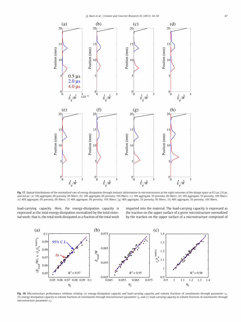
Fig. 17 shows the spatial distribution of the rate of energy dissipa-tion through interface damage at 0.5 μs, 2.0 μs, and 4.0 μs after thebeginning of loading. Eight sub-plots are shown, each correspondingto a microstructure at the corners/limits of range of the parametricstudy. The vertical axes correspond to vertical position within a mi-crostructure. The horizontal axes show the rate of energy dissipationthrough plastic deformation. The rate is normalized to the applied ex-ternal work input rate for a given microstructure. This input rate is onthe order of 105 W. To obtain a complete picture of the spatial distri-bution of the energy dissipation, it is necessary to consider differenttimes. Several trends can be identified from these plots, all of whichare similar to the trends previously observed in the distributions ofthe energy dissipated through interface damage. First, the figuresshow distinct peaks. These peaks correspond to the front of the prop-agating stress wave. Behind the stress wave front, the rate of energydissipation is on the order of 103 times smaller than the rate on thecusp of the wave front, suggesting that, as the stress wave propagatesthrough the microstructure, inelastic deformation occurs primarily atthe wave front and behind the front, little deformation occurs. In thisregard, the spatial distribution of energy dissipation through inelasticdeformation is similar to the distribution of energy dissipationthrough interface damage.
5.3. Microstructure performance-relation maps
The preceding discussion has focused on the load-carrying capacityand components of energy-dissipation capacity, and its individual com-ponents. In particular, the results of parametric studies have beenshown in a format wherein the response variables are functions of thevolume fractions of constituent phases. However, the process of mate-rials' design flows in the opposite direction, from the top–down. Perfor-mance objectives are specified, and then the necessary materialattributes are identified. Structure–property/response trends shown inFig. 18, which relate the load-carrying and energy-dissipation capacitiesto the volume fractions of constituents.
In Fig. 18(a), the vertical axis shows a combined performancemetricdefined as the product of the energy-dissipation capacity and the
(a) (b) (c) (d)
(e) (f) (g) (h)
. .
. .
. .
. .
. .
. .
. .
. .
0.5 μs 2.0 μs 4.0 μs
x10 -6
Fig. 17. Spatial distributions of the normalized rate of energy dissipation through inelastic deformation in microstructures at the eight extremes of the design space at 0.5 μs, 2.0 μs,and 4.0 μs: (a) 10% aggregate, 0% porosity, 0% fibers; (b) 10% aggregate, 0% porosity, 10% fibers; (c) 10% aggregate, 5% porosity, 0% fibers; (d) 10% aggregate, 5% porosity, 10% fibers;(e) 40% aggregate, 0% porosity, 0% fibers; (f) 40% aggregate, 0% porosity, 10% fibers; (g) 40% aggregate, 5% porosity, 0% fibers; (h) 40% aggregate, 5% porosity, 10% fibers.
47J.J. Buck et al. / Cement and Concrete Research 43 (2013) 34–50
load-carrying capacity. Here, the energy-dissipation capacity isexpressed as the total energy dissipation normalized by the total exter-nal work; that is, the total work dissipated as a fraction of the total work
0.05 0.06 0.07 0.08 0.09 0.1
0.05
0.06
0.07
0.08
0.09
0.1
(Eto
tal/W
) x
(t n/t nm
atri
x )
0.045 0.0550.045
0.055
0.065
0.075
Eto
tal/W
R2 = 0.97
fit
95% C.I.
η1
(a) (b)
Fig. 18. Microstructure performance relations relating (a) energy-dissipation capacity an(b) energy-dissipation capacity to volume fractions of constituents through microstructure pmicrostructure parameter η3.
imparted into the material. The load-carrying capacity is expressed asthe traction on the upper surface of a given microstructure normalizedby the traction on the upper surface of a microstructure comprised of
0.9 1 1.1 1.2 1.3 1.40.9
1
1.1
1.2
1.3
1.4
t n/t nmat
rix
0.065 0.075
R2 = 0.95 R2 = 0.98
η2 η3
(c)
d load-carrying capacity and volume fractions of constituents through parameter η1,arameter η2, and (c) load-carrying capacity to volume fractions of constituents through
48 J.J. Buck et al. / Cement and Concrete Research 43 (2013) 34–50
100% cementitious matrix. The horizontal axis is a parameter that de-pends on the volume fractions of the constituents in microstructures.This parameter is obtained through a linear regression analysis andtakes the form of
ETotalW
� �� tn
tmatrixn
!¼ η1 ¼ 0:048
1−Vaf
0:471−Vf
f
3:01−Vp
f
2:6 ; ð13Þ
which provides the best description of the correlation among dissipa-tion, loading carried, and microstructure.
This chart allows the identification of specificmaterialmicrostructuredesigns for any given combination of desired load-carrying capacity andenergy-dissipation. It is useful for identifying microstructure settingsthat may meet desired performance objectives and allows thetrade-offs between conflicting requirements to be explored. It shouldbe noted, however, that such maps are only applicable to loadingunder conditions of nominally uniaxial strain and consider only thevolume fractions of constituents as design variables. The relation clearlycaptures the trade-offs between energy dissipation and strength clearly,i.e., increasing the load-carrying capacity will likely reduce theenergy-dissipation capacity.
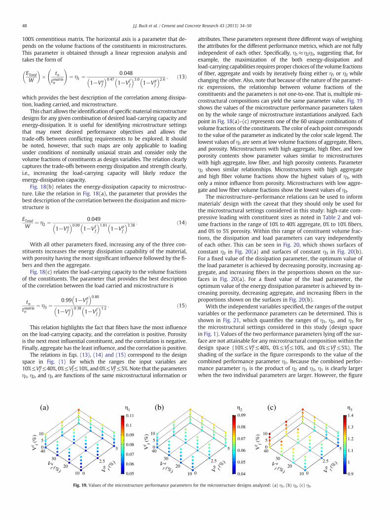
Fig. 18(b) relates the energy-dissipation capacity to microstruc-ture. Like the relation in Fig. 18(a), the parameter that provides thebest description of the correlation between the dissipation andmicro-structure is
ETotalW
¼ η2 ¼ 0:049
1−Vaf
0:091−Vf
f
1:811−Vp
f
3:38 : ð14Þ
With all other parameters fixed, increasing any of the three con-stituents increases the energy dissipation capability of the material,with porosity having the most significant influence followed by the fi-bers and then the aggregate.
Fig. 18(c) relates the load-carrying capacity to the volume fractionsof the constituents. The parameter that provides the best descriptionof the correlation between the load carried and microstructure is
tntmatrixn
¼ η3 ¼0:99 1−Vp
f
0:801−Va
f
0:381−Vf
f
1:2 : ð15Þ
This relation highlights the fact that fibers have the most influenceon the load-carrying capacity, and the correlation is positive. Porosityis the next most influential constituent, and the correlation is negative.Finally, aggregate has the least influence, and the correlation is positive.
The relations in Eqs. (13), (14) and (15) correspond to the designspace in Fig. (1) for which the ranges the input variables are10%≤Vf
a≤40%, 0%≤Vff≤10%, and 0%≤Vf
p≤5%. Note that the parametersη1, η2, and η3 are functions of the same microstructural information or
(a) (b)
0
2.5
5
10
20
30
400
5
10
η1
Vp
f (%
)V af (%)
V af (%)
Vf f (
%)
Vf f (
%)
0.05
0.06
0.07
0.08
0.09
0.1
0.11
010
20
30
400
5
10
Fig. 19. Values of the microstructure performance parameters fo
attributes. These parameters represent three different ways of weighingthe attributes for the different performance metrics, which are not fullyindependent of each other. Specifically, η1≈η2η3, suggesting that, forexample, the maximization of the both energy-dissipation andload-carrying capabilities requires proper choices of the volume fractionsof fiber, aggregate and voids by iteratively fixing either η1 or η2 whilechanging the other. Also, note that because of the nature of the paramet-ric expressions, the relationship between volume fractions of theconstituents and the parameters is not one-to-one. That is, multiple mi-crostructural compositions can yield the same parameter value. Fig. 19shows the values of the microstructure performance parameters takenon by the whole range of microstructure instantiations analyzed. Eachpoint in Fig. 18(a)–(c) represents one of the 60 unique combinations ofvolume fractions of the constituents. The color of each point correspondsto the value of the parameter as indicated by the color scale legend. Thelowest values of η1 are seen at low volume fractions of aggregate, fibers,and porosity. Microstructures with high aggregate, high fiber, and lowporosity contents show parameter values similar to microstructureswith high aggregate, low fiber, and high porosity contents. Parameterη2 shows similar relationships. Microstructures with high aggregateand high fiber volume fractions show the highest values of η3, withonly a minor influence from porosity. Microstructures with low aggre-gate and low fiber volume fractions show the lowest values of η3.
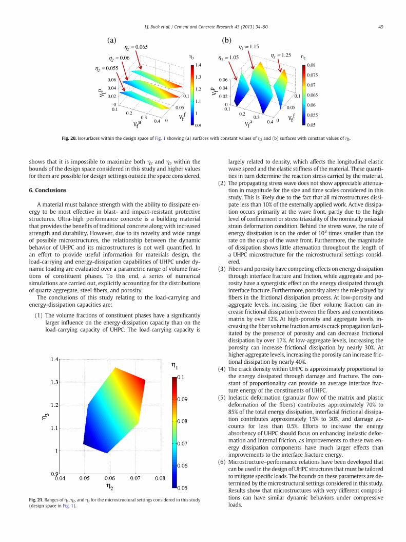
The microstructure–performance relations can be used to informmaterials' design with the caveat that they should only be used forthe microstructural settings considered in this study: high-rate com-pressive loading with constituent sizes as noted in Table 2 and vol-ume fractions in the range of 10% to 40% aggregate, 0% to 10% fibers,and 0% to 5% porosity. Within this range of constituent volume frac-tions, the dissipation and load parameters can vary independentlyof each other. This can be seen in Fig. 20, which shows surfaces ofconstant η2 in Fig. 20(a) and surfaces of constant η3 in Fig. 20(b).For a fixed value of the dissipation parameter, the optimum value ofthe load parameter is achieved by decreasing porosity, increasing ag-gregate, and increasing fibers in the proportions shown on the sur-faces in Fig. 20(a). For a fixed value of the load parameter, theoptimum value of the energy dissipation parameter is achieved by in-creasing porosity, decreasing aggregate, and increasing fibers in theproportions shown on the surfaces in Fig. 20(b).
With the independent variables specified, the ranges of the outputvariables or the performance parameters can be determined. This isshown in Fig. 21, which quantifies the ranges of η1, η2, and η3 forthe microstructural settings considered in this study (design spacein Fig. 1). Values of the two performance parameters lying off the sur-face are not attainable for any microstructural composition within thedesign space (10%≤Vf
a≤40%, 0%≤Vff≤10%, and 0%≤Vf
p≤5%). Theshading of the surface in the figure corresponds to the value of thecombined performance parameter η1. Because the combined perfor-mance parameter η1 is the product of η2 and η3, η1 is clearly largerwhen the two individual parameters are larger. However, the figure
(c)
Vp
f (%
)
Vp
f (%
)V af (%)
Vf f (
%)
2.5
5
η2
0.04
0.05
0.06
0.07
0.08
0.09
0
2.5
5
10
20
30
400
5
10
η3
0.9
1
1.1
1.2
1.3
1.4
r the microstructure designs analyzed: (a) η1, (b) η2, (c) η3.
η2 =
η2 =
η2 =
η3 = η3 = η3 =
0.10.2
0.30.4 0
0.05
0.1
0
0.02
0.04
0.06
0.10.2
0.30.4 0
0.05
0.1
0
0.02
0.04
0.06
(a) (b)
0.9
1
1.1
1.2
1.3
1.4 0.08
η2η3
0.075
0.07
0.065
0.06
0.055
0.05
0.055
1.15
1.251.05
0.065
0.06
Fig. 20. Isosurfaces within the design space of Fig. 1 showing (a) surfaces with constant values of η2 and (b) surfaces with constant values of η3.
49J.J. Buck et al. / Cement and Concrete Research 43 (2013) 34–50
shows that it is impossible to maximize both η2 and η3 within thebounds of the design space considered in this study and higher valuesfor them are possible for design settings outside the space considered.
6. Conclusions
A material must balance strength with the ability to dissipate en-ergy to be most effective in blast- and impact-resistant protectivestructures. Ultra-high performance concrete is a building materialthat provides the benefits of traditional concrete along with increasedstrength and durability. However, due to its novelty and wide rangeof possible microstructures, the relationship between the dynamicbehavior of UHPC and its microstructures is not well quantified. Inan effort to provide useful information for materials design, theload-carrying and energy-dissipation capabilities of UHPC under dy-namic loading are evaluated over a parametric range of volume frac-tions of constituent phases. To this end, a series of numericalsimulations are carried out, explicitly accounting for the distributionsof quartz aggregate, steel fibers, and porosity.
The conclusions of this study relating to the load-carrying andenergy-dissipation capacities are:
(1) The volume fractions of constituent phases have a significantlylarger influence on the energy-dissipation capacity than on theload-carrying capacity of UHPC. The load-carrying capacity is
Fig. 21. Ranges of η1, η2, and η3 for the microstructural settings considered in this study(design space in Fig. 1).
largely related to density, which affects the longitudinal elasticwave speed and the elastic stiffness of thematerial. These quanti-ties in turn determine the reaction stress carried by the material.
(2) The propagating stress wave does not show appreciable attenua-tion in magnitude for the size and time scales considered in thisstudy. This is likely due to the fact that all microstructures dissi-pate less than 10% of the externally applied work. Active dissipa-tion occurs primarily at the wave front, partly due to the highlevel of confinement or stress triaxiality of the nominally uniaxialstrain deformation condition. Behind the stress wave, the rate ofenergy dissipation is on the order of 103 times smaller than therate on the cusp of the wave front. Furthermore, the magnitudeof dissipation shows little attenuation throughout the length ofa UHPC microstructure for the microstructural settings consid-ered.
(3) Fibers and porosity have competing effects on energy dissipationthrough interface fracture and friction, while aggregate and po-rosity have a synergistic effect on the energy dissipated throughinterface fracture. Furthermore, porosity alters the role played byfibers in the frictional dissipation process. At low-porosity andaggregate levels, increasing the fiber volume fraction can in-crease frictional dissipation between the fibers and cementitiousmatrix by over 12%. At high-porosity and aggregate levels, in-creasing the fiber volume fraction arrests crack propagation facil-itated by the presence of porosity and can decrease frictionaldissipation by over 17%. At low-aggregate levels, increasing theporosity can increase frictional dissipation by nearly 30%. Athigher aggregate levels, increasing the porosity can increase fric-tional dissipation by nearly 40%.
(4) The crack density within UHPC is approximately proportional tothe energy dissipated through damage and fracture. The con-stant of proportionality can provide an average interface frac-ture energy of the constituents of UHPC.
(5) Inelastic deformation (granular flow of the matrix and plasticdeformation of the fibers) contributes approximately 70% to85% of the total energy dissipation, interfacial frictional dissipa-tion contributes approximately 15% to 30%, and damage ac-counts for less than 0.5%. Efforts to increase the energyabsorbency of UHPC should focus on enhancing inelastic defor-mation and internal friction, as improvements to these two en-ergy dissipation components have much larger effects thanimprovements to the interface fracture energy.
(6) Microstructure–performance relations have been developed thatcan be used in the design of UHPC structures thatmust be tailoredtomitigate specific loads. The bounds on these parameters are de-termined by themicrostructural settings considered in this study.Results show that microstructures with very different composi-tions can have similar dynamic behaviors under compressiveloads.
50 J.J. Buck et al. / Cement and Concrete Research 43 (2013) 34–50
Finally, it is instructive to note that the relations and results de-scribed in this paper are applicable for the design space, material set-ting and loading conditions considered. Factors not consideredinclude, e.g., the variation of pore size and fiber diameters. These fac-tors are additional dimensions in the microstructure design space andshould be considered in future studies. It is important to note thathigher temperatures can result from high strain-rate dynamicloading, leading to thermally driven events in materials. The analysisreported here does not account for processes such as temperature-induced phase transformation in the quartz aggregate and thermalsoftening of the steel fibers or cementitious matrix. The highpressures resulting from the dynamic loading can also induce phasetransformations in the constituents. The α-quartz-to-coesite phasetransformation is one such example. The effect of this phase transfor-mation is analyzed in [21] as a companion study reported in thispaper. Finally, it should be pointed out that, although the study hereconcerns only one form of UHPC, the framework developed is applica-ble to other heterogeneous materials. For example, there has beenincreasing interest in using polymeric fibers (e.g. PVA and polypro-pylene) or carbon nanofibers instead of steel fibers in UHPC. Similarstudies can be carried out for such material systems using thisframework.
Acknowledgments
This work was sponsored by the U.S. Department of Homeland Se-curity, Science and Technology Directorate, Infrastructure Protectionand Disaster Management Division: Ms. Mila Kennett, Program Man-ager. The research was performed under the direction of Dr. Beverly P.DiPaolo, Engineering Research and Development Center (ERDC), U.S.Army Corps of Engineers. Permission to publish was granted by theDirector, Geotechnical and Structures Laboratory, ERDC. Approvedfor public release; distribution is unlimited.
This research is part of a basic research demonstration project onimprovised explosive device effects and is performed in collaborationwith the ERDC — Geotechnical and Structures Laboratory (GSL), OakRidge National Laboratory, and Sandia National Laboratories.
Views expressed are solely those of the authors and do not necessar-ily reflect the opinions or policy of theU.S. Department of Homeland Se-curity, the U.S. Army Corps of Engineers, or any other agency of the U.S.government, and no official endorsement should be inferred.
The authors would also like to thank Brett Ellis and Chris Lammi fortheir contributions to the development of the concrete structure instan-tiation code used in this study. MZ also acknowledges support from theNational Research Foundation of Korea through WCU Grant No.R31-2009-000-10083-0 at Seoul National University where he is aWCU professor.
References
[1] Z. Rong, W. Sun, Y. Zhang, Dynamic compression behavior of ultra-high perfor-mance cement based composites, Int. J. Impact Eng. 37 (2010) 515–520.
[2] W. Sun, J. Lai, Dynamic mechanical behavior and durability of ultrahigh-performance cementitious composite, Key Eng. Mater. 400 (2009) 3–15.
[3] G.K. Schleyer, S.J. Barnett, S.G. Millar, G. Wight, Modeling the Response of UHPFRCPanels to Explosive Loading, in: International Conference on Structures underShock and Impact, WIT Press, Tallinn, Estonia, 2010, pp. 173–184.
[4] M. Rebentrost, G. Wight, Behavior and resistance of ultra high-performance con-crete to blast effects, in: S. Sturwald (Ed.), Second International Symposium onUltra High-Performance Concrete, Kassel University Press, Kassel, Germany,2008, pp. 735–742.
[5] B. Cavil, M. Rebentrost, V. Perry, Ductal — An Ultra-High Performance Material forResistance to Blast and Impacts, in: 1st Specialty Conference on Disaster Mitigation,Calgary, Alberta, Canada, 2006.
[6] Z. Mroz, M. Angelillo, Rate-Dependent Degradation Model for Concrete and Rock,in: International Symposium on Numerical Models in Geomechanics, Zurich,1982, pp. 208–217.
[7] G.Z. Voyiadjis, Z.N. Taqieddin, Elastic plastic and damage model for concretematerials: Part I — Theoretical formulation, Int. J. Struct. Changes Solids 1(2009) 31–59.
[8] D. Fanella, D. Krajcinovic, A micromechanical model for concrete in compression,Eng. Fract. Mech. 29 (1988) 49–66.
[9] P. Grassl, M. Jirásek, Damage-plastic model for concrete failure, Int. J. Solids Struct.43 (2006) 7166–7196.
[10] Z. Tu, Y. Lu, Evaluation of typical concrete material models used in hydrocodes forhigh dynamic response simulations, Int. J. Impact Eng. 36 (2009) 132–146.
[11] S.W. Park, Q. Xia, M. Zhou, Dynamic behavior of concrete at high strain rates andpressures: II. Numerical simulation, Int. J. Impact Eng. 25 (2001) 887–910.
[12] F.T.S. Aragao, Y.-R. Kim, J. Lee, D.H. Allen, Micromechanical model for heteroge-neous asphalt concrete mixtures subjected to fracture failure, J. Mater. Civ. Eng.23 (2011) 30–38.
[13] Z. Xu, H. Hao, H.N. Li, Mesoscale modelling of fibre reinforced concrete materialunder compressive impact loading, Constr. Build. Mater. 26 (2012) 274–288.
[14] J.E. Bolander, Y.M. Lim, Simulations of Fiber Distribution Effects in Fiber-ReinforcedCement Composites, in: AIP Conference Proceedings, 973, 2008, pp. 507–512.
[15] C. Lammi, D. McDowell, M. Zhou, Computation of the Mesoscale Dynamic Fractureand Dissipation Behavior of Concrete, Comput. Mech. (submitted for publication).
[16] B. Ellis, D. McDowell, M. Zhou, Energy Dissipation and Evolving Strength ofUltra-High-Performance Fiber-Reinforced Concrete (UHPFRC), in: 3rd InternationalSymposium on Ultra-High Performance Concrete and Nanotechnology for High Per-formance Construction Materials, Kassel, Germany, submitted for publication.
[17] E.N. Landis, J.E. Bolander, Explicit representation of physical processes in concretefracture, J. Phys. D: Appl. Phys. 42 (2009) 214002.
[18] Y. Farnam, S. Mohammadi, M. Shekarchi, Experimental and numerical investiga-tions of low velocity impact behavior of high-performance fiber-reinforced ce-ment based composite, Int. J. Impact Eng. 37 (2010) 220–229.
[19] F. Bencardino, L. Rizzuti, G. Spadea, R. Swamy, Stress–strain behavior of steelfiber-reinforced concrete in compression, J. Mater. Civ. Eng. 20 (2008) 255–263.
[20] H.W. Reinhardt, P. Rossi, R. Baggott, G. Balazs, J.E. Bolander, A.E. Brandt, M.Cheyrezy, K. Chong, L. Eredelyi, H. Krenchel, D. Lange, C. Leung, V.C. Li, H.Mihashi, A.E. Naaman, V.S. Parameswaran, H. Stang, Future research needs inthe field of HPFRCC, in: A.E. Naaman, H.W. Reinhardt (Eds.), High PerformanceFiber Reinforced Cement Composites, 2, E&FN Spon, Ann Arbor, USA, 1995, p. 463.
[21] J.J. Buck, D.L. McDowell, M. Zhou, Effect of α-quartz-to-coesite silica phase trans-formation on the dynamic behavior of UHPC, submitted for, publication.
[22] ABAQUS Theory Manual, Simulia, 2010.[23] D.C. Drucker, W. Prager, Soil mechanics and plastic analysis or limit design, Q.
Appl. Math. 10 (1952) 157–165.[24] X.Q. Zhou, V.A. Kuznetsov, H. Hao, J. Waschl, Numerical prediction of concrete
slab response to blast loading, Int. J. Impact Eng. 35 (2008) 1186–1200.[25] V. Li, Determination of interfacial debond mode for fiber-reinforced cementitious
composites, J. Eng. Mech. 120 (1994) 707–720.[26] B. Shen, G.H. Paulino, Identification of cohesive zone model and elastic parame-
ters of fiber-reinforced cementitious composites using digital image correlationand a hybrid inverse technique, Cem. Concr. Compos. 33 (2011) 572–585.
[27] A. Hillerborg, M. Modeer, P.E. Petersson, Analysis of crack formation and crackgrowth in concrete by means of fracture mechanics and finite elements, Cem.Concrete Res. 6 (1976) 773–782.
[28] A. Gens, I. Carol, E.E. Alonso, An interface element formulation for the analysis ofsoil-reinforcement interaction, Comput. Geotech. 7 (1989) 133–151.
[29] P.P. Camanho, C.G. Davila, M.F. de Moura, Numerical simulation of mixed-modeprogressive delamination in composite materials, J. Compos. Mater. 37 (2003)1415–1438.
[30] P.E. Petersson, Crack growth and development of fracture zone in plane concreteand similar materials, Lund Institute of Technology, Lund, Sweden, 1981.
[31] J. Roesler, G.H. Paulino, K. Park, C. Gaedicke, Concrete fracture prediction using bi-linear softening, Cem. Concr. Compos. 29 (2007) 300–312.
[32] M.L. Benzeggagh, M. Kenane, Measurement of mixed-mode delamination fracturetoughness of unidirectional glass/epoxy composites with mixed-mode bendingapparatus, Compos. Sci. Technol. 56 (1996) 439–449.
[33] A.B. Abell, D.A. Lange, Fracture mechanics modeling using images of fracturedsurfaces, Int. J. Solids Struct. 35 (1998) 4025–4033.
[34] G.T. Camacho, M. Ortiz, Computational modelling of impact damage in brittle ma-terials, Int. J. Solids Struct. 33 (1996) 2899–2938.
[35] In: Building Code Requirements for Structural Concrete (ACI 318–95), AmericanConcrete Institute, Farmington Hills, Michigan, 1995, p. 369.
[36] I. Carol, C.M. López, O. Roa, Micromechanical analysis of quasi-brittle materialsusing fracture-based interface elements, Int. J. Numer. Methods Eng. 52 (2001)193–215.
[37] C.M. Sayers, M. Kachanov, A simple technique for finding effective elastic constantsof cracked solids for arbitrary crack orientation statistics, Int. J. Solids Struct. 27(1991) 671–680.
[38] F. Homand, D.Hoxha, T. Belem,M.-N. Pons, N. Hoteit, Geometric analysis of damagedmicrocracking in granites, Mech. Mater. 32 (2000) 361–376.