central office grounding
TRANSCRIPT


RUS Bulletin 1751F-810 Page 2
TABLE OF CONTENTS 1. GENERAL.....................................................6 1.1 Electronic Telecommunications Systems ....................6 1.2 The Basic Grounding System ...............................6 1.3 The Single Point Grounding System ........................6 1.4 Equipment Manufacturers ..................................6 1.5 Resistance ...............................................6
2. DEFINITIONS.................................................6 2.1 Introduction .............................................6 2.2 Building Structural Ground ...............................7 2.3 Cable Entrance Ground Bar (CEGB) .........................7 2.4 Central Office Ground Field (COGF) .......................7 2.5 Collocated Switching Systems .............................7 2.6 Electrostatic Discharge (ESD) Protection .................7 2.7 Fuse Link ................................................7 2.8 Green Wire Ground ........................................7 2.9 Ground Loop ..............................................7 2.10 Ground Window Bar (GWB) .................................7 2.11 Insulating Joints .......................................7 2.12 Intermediate Ground Bar (IGB) ...........................8 2.13 Isolated Ground Zone (IGZ) ..............................8 2.14 Main Distributing Frame (MDF) ...........................8 2.15 Master Ground Bar (MGB) .................................8 2.16 MDF Ground Bar (MDFGB) ..................................8 2.17 MDF Protector Assembly ..................................8 2.18 Metallic Water Pipe .....................................8 2.19 Multigrounded Neutral (MGN) .............................8 2.20 Personnel Discharge Plates ..............................9 2.21 Single Point Grounding ..................................9 2.22 Surge Absorbers (A) .....................................9 2.23 Surge Producers (P) .....................................9
3. SINGLE POINT GROUNDING......................................9 3.1 Single Point Grounding ...................................9 3.2 Surge Potentials .........................................9 3.3 The Purpose of Single Point Grounding ....................9 3.4 MGB Bonding Configuration ...............................10 3.5 Potential of IGZ Equipment ..............................10
4. MASTER GROUND BAR (MGB)....................................10 4.1 Purpose and General Description .........................10 4.2 Surge Producers (P Section of MGB) ......................11 4.3 Surge Absorbers (The A section of MGB) ..................12 4.4 Non-IGZ Grounds (N section of MGB) ......................14 4.5 IGZ Grounds (I Section of MGB) ..........................14 4.6 Ground Resistance Objective .............................14
5. CENTRAL OFFICE GROUND WINDOW BAR (GWB).....................16 5.1 Equipment Ground Originating inside IGZ .................16 5.2 Equipment Located in a Remote Area ......................16 5.3 Connect Each GWB to the MGB .............................16 5.4 The Conductors Terminating on the GWB ...................16

RUS Bulletin 1751F-810 Page 3
5.5 The Frame Grounds of Equipment Located inside IGZ .......16
6. ISOLATED GROUND ZONE (IGZ)..................................18 6.1 Introduction ............................................18 6.2 Installation and Bonding of Metal Framework .............18
7. MAIN DISTRIBUTING FRAME (MDF)..............................18 7.1 Special Grounding Considerations ........................18 7.2 Transmission Equipment Termination and Protection .......19 7.3 Entrance and Tip Cables .................................19 7.4 Protection ..............................................21 7.5 Current Limitation ......................................22 7.6 Heat Coils ..............................................22
8. GROUNDING CONDUCTOR SIZING, ROUTING AND TERMINATING........22 8.1 Sizing of Protective Grounding Conductors ...............22 8.2 The Planning and Installation of the Wiring .............23 8.3 Stenciling and Tagging ..................................24
9. POWER SERVICE PROTECTION...................................25 9.1 The Minimum Protection for AC Power Serving Central Office Buildings ....................................................25 9.2 Power Arrester Protecting Kilowatt-hour Meter ...........25 9.3 Protecting the AC Power Service Entering a Central Office25
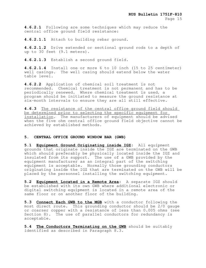
10. RADIO OR MICROWAVE INSTALLATIONS..........................26 10.1 Radio or Microwave Towers Which Are Located on or in Close Proximity to CO Buildings ..............................26 10.2 Protection of the Tower and Associated Equipment .......26 10.3 Bonding Tower Ground to CO Grounding Systems ...........26
11. ELECTROSTATIC & ELECTROMAGNETIC FIELD EFFECTS.............26 11.1 Static Electricity .....................................26 11.2 FET, MOS, and CMOS .....................................26 11.3 The Accumulation of Electrostatic Discharge by a Human Body .........................................................27 11.4 Electrostatic Conditions That Produce Equipment Problems27
12. GENERAL ENVIRONMENTAL AND HANDLING REQUIREMENTS FOR ELECTROSTATIC SENSITIVE EQUIPMENT..............................27 12.1 Proper Environmental and Handling Considerations .......27 12.2 Environmental Conditions ...............................27 12.3 Precautions for Maintenance Procedure ..................27 12.4 Precautions for Operating Motor Driven Devices .........28 12.5 Precautions for Memory Devices .........................29
13. DISCHARGE PLATES..........................................29 13.1 For Protection of Static Sensitive Equipment ...........29 13.2 Installation of Electrostatic Discharge Plates .........29 13.3 Supplemental Discharge Plates ..........................30 13.4 Warning Signs ..........................................30
APPENDIX A: VOLTAGE FROM SURGE CURRENTS.......................38 APPENDIX B: PROTECTION FOR ANTENNA INSTALLATIONS..............42 APPENDIX C: ANALYSIS OF CENTRAL OFFICE GROUNDING SYSTEMS......55 TABLES Table C-1......................................................67

RUS Bulletin 1751F-810 Page 4 FIGURES Figure 1: Master Ground Bar....................................31 Figure 2: Outdoor Grounding Conductor Connections..............32 Figure 3: Entrance and Tip Cable Arrangements..................33 Figure 4: Cable Entrance without Vault.........................34 Figure 5: Typical Power Service Protector Installation.........35 Figure 6: Central Office Protection Grounding..................36 Figure 7: Maximum Conductor Length to Meet the Grounding Conductor Resistance Objectives......................37 Figure B1: Self Supporting Tower...............................47 Figure B2: Bonding Details.....................................48 Figure B3: Guyed Tower Installation............................49 Figure B4: Pole Mounted Installation...........................50 Figure B5: Building Mounted Installation.......................51 Figure B6: Tower Ground Kit Installation.......................52 Figure B7: Entrance Grounding at Central Office................53 Figure C1: Master Grounding Bar Currents.......................64 Figure C2: CEGB Currents.......................................65 Figure C3: Undesirable Reduction in Size of Grounding Conductor...........................................66 Figure C4: Undesirable Butt-Splice.............................67 INDEX: Protection Protection, Central Office
ABBREVIATIONS
A Surge Absorbers, a section of the MGB Amperes, unit for measuring the flow of current ANSI American National Standards Institute CATV Community Antenna Television, cable CEGB Cable Entrance Ground Bar CMOS Complementary Metal Oxide Semiconductor CO Central Office COGF Central Office Ground Field ESD Electrostatic Discharge FET Field Effect Transistor GWB Ground Window Bar I IGZ Grounds section of the MGB IGB Intermediate Ground Bar IGZ Isolated Ground Zone MCM One Thousand Circular Mils

RUS Bulletin 1751F-810 Page 5
MDF Main Distributing Frame MDFB MDF Ground Bar MGB Master Ground Bar MGN Multigrounded Neutral MOS Metal Oxide Semiconductor µH Microhenries N Non-IGZ Grounds section of the MGB NEC National Electrical Code NFPA National Fire Protection Association P Surge Producers section of the MGB PVC Polyvinyl Chloride RUS Rural Utilities Service SCR Silicon Controlled Rectifier TE&CM Telecommunications Engineering and Construction Manual
DEFINITIONS
Section 2 of this bulletin is devoted to definitions.

RUS Bulletin 1751F-810 Page 6 1. GENERAL 1.1 Electronic Telecommunications Systems may experience malfunctions, erratic operation, and total disruption of service as a result of excessive induced transient voltages which may be introduced through incoming circuits, the central office grounding system, or by electrostatic action. Electronic switching systems are vulnerable to voltage sources because of the fragile nature of semiconductor components and their fast transient response characteristics. Semiconductors typically have low breakdown voltage ratings and can be permanently damaged by excessive voltage and current spikes. 1.2 The Basic Grounding System discussed in this section is primarily designed for single floor office buildings and outside cabinets which are typical in RUS financed systems. 1.3 The Single Point Grounding System described in this bulletin meets the protection requirements of most central office and other electro-optic equipment manufacturers. The described methods should be followed unless there are compelling reasons for change (see 1.4). 1.4 Equipment Manufacturers may request grounding systems that exceed those recommended herein. Manufacturers might include a rigid, low maximum resistance requirement for the equipment site ground fields or various forms of extraordinary lightning protection. 1.5 Resistance: This bulletin is based on resistance since this is a primary parameter that is readily understood. However, the essential factor in telecommunications service system protection is the grounding system impedance, especially the reactance component, of the grounding conductors. The general guidelines presented in this bulletin are based on providing a system having a relatively low overall grounding system impedance to the flow of lightning and power fault currents. 2. DEFINITIONS 2.1 Introduction: The following terms are defined as an aid to understanding their usage in this bulletin. These terms are commonly used for describing telecommunications grounding systems. Different terms have been used by individual manufacturers and operating companies other than those commonly used. Such terms are included in parentheses at the end of each definition, where applicable. 2.2 Building Structural Ground: A grounding electrode source provided by structural steel and/or reinforcing steel rods

RUS Bulletin 1751F-810 Page 7
contained within the building walls, roofs, floors, footing, or foundations. 2.3 Cable Entrance Ground Bar (CEGB): A copper ground bar to terminate incoming telephone cable shields on a common connection point. The bar is normally located close to the entrance location (Cable Vault Ground Bar). 2.4 Central Office Ground Field (COGF): A series of interconnected ground rods, buried perimeter cable or a metallic well casing for a low impedance path to earth ground (Central Office Ground Grid). 2.5 Collocated Switching Systems: Two or more switching (i.e. central office or remote switching terminals) systems at a single location. 2.6 Electrostatic Discharge (ESD) Protection: The protection of electronic components from static voltage discharges. Static charges are commonly generated by personnel or air moving in a work area where the relative humidity is low. 2.7 Fuse Link: A section of fine wire in a conductor designed to melt during a current-surge condition. This element normally protects from currents which could otherwise heat conductors and start fires. 2.8 Green Wire Ground: A normally non-current carrying conductor that protects personnel and equipment. The green color code distinguishes the lead from the current carrying grounded conductors (neutrals) which are natural, gray or white (Equipment Grounding Conductor). 2.9 Ground Loop: Ground loops exist when there is more than one electrical path to a ground connection. Such parallel paths to ground are normally not a problem if associated with nonsensitive circuitry located outside the Isolated Ground Zone (IGZ.) Ground loops are undesirable for equipment located in the IGZ. 2.10 Ground Window Bar (GWB): A copper bar for the common connection of all equipment located in the IGZ. See Green Wire Ground, Master Ground Bar. 2.11 Insulating Joints: Nonconducting inserts in metal framework of equipment located in the IGZ. These inserts insulate the IGZ equipment from outside ground connections. 2.12 Intermediate Ground Bar (IGB): A copper bar, insulated from its support, used to connect a ground wire from the Master Ground Bar (MGB) (see Ground Window Bar) to several racks or frames of equipment, usually in the non-IGZ area, but not to include battery (+) from the main power board.

RUS Bulletin 1751F-810 Page 8 2.13 Isolated Ground Zone (IGZ): A dedicated area within an office building where all equipment is electrically insulated from all external grounds except through a single ground connection between the GWB and the MGB. The isolated area should preferably extend a minimum of six feet (two meters) on all sides from the equipment frames and framework and where practical be separated from other equipment by permanent walls. The IGZ will normally house sensitive electronic components (Isolated Area). 2.14 Main Distributing Frame (MDF): A distributing frame where outside plant cables are terminated on vertical protection assemblies. Cable pairs are also cross-connected on this frame to equipment terminated on horizontal blocks. 2.15 Master Ground Bar (MGB): A copper bar used as single point connection for surge producers, surge absorbers, non-IGZ equipment grounds, and IGZ equipment grounds. The MGB is normally non-current carrying and isolated from the building/structural ground. 2.16 MDF Ground Bar (MDFGB): A copper bar commonly found at the bottom of the MDF for the connection of tip cable shields and MDF protector assemblies. It may be used as a connection point for MDF ironwork (see 7.1.3). The MDFB may be used as an MGB in small offices (Entrance Cable Protector Bar). 2.17 MDF Protector Assembly: An assembly consisting of a protector module and a connector module. 2.18 Metallic Water Pipe: An outdoor section of buried metallic water pipe at least 10 feet (3.0 meters) in length and owned by the telecommunications company. 2.19 Multigrounded Neutral (MGN): A continuous electrical conductor on a power distribution system with multiple direct connections to earth ground at multiple points. In this system, at least 4 grounds have to be provided in each mile of line (2.5 grounds in each kilometer of line), not including grounds at individual services. This multiple grounding arrangement provides a very low impedance path to earth ground for absorbing lightning and other surges. It also provides a return path for residual (unbalanced) currents resulting from less than perfect balance on associated three-phase power distribution systems. 2.20 Personnel Discharge Plates: Plates found in equipment areas containing voltage-sensitive electronic equipment. These plates are connected to ground and are used to discharge body voltages to ground rather than through sensitive electronic components by accidental contact. 2.21 Single Point Grounding: A grounding system using a single point, usually the MGB, for a zero reference potential to ground for an entire system. While the voltage at this connection point

RUS Bulletin 1751F-810 Page 9
may rise above zero volts-to-earth-ground under fault conditions, the entire system will also rise at the same rate to the same voltage. This helps minimize any circulating currents between components from lightning or power surges. 2.22 Surge Absorbers (A): Paths with a low impedance connection to a remote earth ground. A grounding element which has a low impedance path to earth ground is considered a primary surge absorber. There are three primary surge absorbers: (1) the service system ground field, (2) the power system multigrounded neutral (MGN), and (3) a metallic water system. 2.23 Surge Producers (P): Connections to metallic sources of lightning and/or power surges. For example, radio/microwave towers, telephone cable shields, telephone cable pairs and power system conductors. 3. SINGLE POINT GROUNDING 3.1 Single Point Grounding: There is a need to control the high voltage differences produced between the ends of single conductors by fast rising electrical surges. Reference Appendix A for a discussion of the voltage effects from fast rising surge currents. 3.2 Surge Potentials need to be equalized through bonding of central office or other service system ground elements. Among these ground elements are: Surge Producers (P), Surge Absorbers (A), Non-IGZ equipment grounds (N), and IGZ equipment grounds (I). See Figure 1, “Master Ground Bar.” 3.3 The Purpose of Single Point Grounding is to reduce voltage differences and control surge currents. The basic elements of a single point grounding system include the following: 3.3.1 A Master Ground Bar (MGB) with connections grouped to confine lightning and power surge activity. This is the point for establishing a common reference plane, with respect to earth ground, for the entire system. 3.3.2 A Ground Window Bar (GWB) establishes a single location for grounding sensitive electronic equipment within the IGZ. Section I of the MGB (see Section 4) provides a single-point termination and ground reference to which the GWB and associated electronic equipment are bonded. 3.3.3 An Isolated Ground Zone (IGZ) surrounds the electronic switch and other sensitive electronic equipment. The IGZ will consistently have the same voltage potential as the GWB. 3.4 MGB Bonding Configuration: A high momentary or transitory voltage rise that can occur between the point of strike and

RUS Bulletin 1751F-810 Page 10 point(s) of dissipation would result from direct or indirect lightning strike to cable or other outside plant connected to the MGB. The MGB bonding configurations illustrated, in Figure 1 and Figure 6, “Central Office Protection Grounding,” allow high current surges to be concentrated and dissipated through the P and A sections of the bar. This maintains the lowest possible electric potential at the point of MGB-GWB connection. The connection sequence of P-A-N-I as shown in Figure 1 is important to assure the overall protection effectiveness. 3.5 Potential of IGZ Equipment: All equipment in the IGZ electrically floats at essentially the same potential as the GWB when a single-point grounding is used. When all equipment is at the same potential, no damaging voltages appear across sensitive components and surge currents are eliminated. 4. MASTER GROUND BAR (MGB) 4.1 Purpose and General Description: The MGB is the hub of the basic central office grounding system. It is a common point of connection for the P-surge producers and A-surge absorbers, and equipment grounds for both the N-nonisolated and I-isolated equipment areas. The sizing of ground conductors is discussed in Section 8. The MGB is a copper bar insulated from its support. The MGB may be located either on a wall near the MDF, or on the cable vault wall. In small offices the MGB may be located on the MDF as described in 4.2.2 and 7.1.4. The various connections to the MGB should be tagged or stenciled for identification as described in 8.3. 4.2 Surge Producers (P section of MGB): The MGB is the preferred connection point for surge producers such as MDF protector ground, entrance ground bar, etc. 4.2.1 Cable Entrance Ground Bar (CEGB): The CEGB is a copper bar insulated from its support. Cable shields should be bonded directly to a CEGB in offices with a cable vault. The CEGB is connected by an insulated conductor sized according to Section 8 using the most direct route to the MGB. 4.2.2 MDF Ground Bar (MDFGB): The main frame protector blocks should be bonded directly to the MDFGB. A detailed discussion of MDF protection is found in Section 7. The MDFGB is the bonding point for terminating the MDF end of tip cable shields to ground. The MDFGB may be used as the MGB in very small offices where installation of a wall-mounted MGB is impractical. With this application, the bar should be insulated from its support and have sufficient length for the connection sequence shown1 in Figure 1. It is important, that the integrity of all sections of 1 For presentation purpose the MGB shown in Figure 6 is square shaped to neatly arrange the multitude of connections involved. In reality the MDF is a straight slab of copper not squared shaped.

RUS Bulletin 1751F-810 Page 11
the bar are preserved for the life of the ground bar arrangement. The MDFB may be insulated from its support as required by the manufacturer. 4.2.3 Radio and Microwave Equipment Grounds: Connect all indoor cabinets of the radio and microwave equipment directly to the MGB. No connections should be made to the GWB or other central office ironwork. Where the MDFGB is used as the MGB, these equipment grounds should be connected to the P section of the bar. Radio/microwave towers have their own outdoor, dedicated grounding systems. Surge voltages should be equalized by bonding the dedicated grounding system to the central office ground field outside the building for personnel safety and equipment protection. This connection is discussed in 4.3.2. 4.2.4 Standby Power Plant Framework Ground: Unless the Central Office ground field is within three feet of the generator frame, a ground rod is recommended. This ground rod should be driven into the earth as close as possible to the generator frame and where someone would be expected to be in contact with both the frame and the ground. This ground rod should be solidly bonded to the generator frame using a conductor sized according to NEC Article 250-95. 4.2.4.1 The ground rod should be installed in addition to the connection to the MGB. Because the generator frame is connected to the MGB via equipment grounding connections (the generator installer provides), the frame will be at the electrical potential of the MGB. This potential could be much different than the potential existing on the surface of the soil in the immediate vicinity of the generator. (The generator installer connects the NEC Article 250-50(a) required green wire equipment grounding conductor from the generator frame to the electric service neutral which, in turn, is connected to the MGB.) With the frame connected to the MGB without a ground rod installed, there is a possibility for a potential difference (voltage) between the frame and the soil. With the ground rod installed, the frame-to-soil potential differences are minimized. 4.2.4.2 Because one can never be certain of the exact location of buried facilities and in the interests of being consistent from installation to installation, it is better to simply standardize on and always install a ground rod. NEC Article 250-91(c), “Supplementary Grounding” discusses this permissible, not mandatory, method of augmenting the grounding. The equipment grounding conductor is detailed in Article 250-91(b). 4.3 Surge Absorbers (The A section of MGB): The MGB is the preferred connection point for the three primary surge absorbers. They are the power system multigrounded neutral, the central office ground field, and the metallic water system. Bonding of the power neutral and water pipe, on the MGB does not replace the

RUS Bulletin 1751F-810 Page 12 requirements of the National Electrical Code for separately bonding the commercial power service. 4.3.1 Multigrounded Neutral (MGN): The MGN with its multiple connections to earth throughout the power system normally has a low impedance to earth ground. Because of its low impedance the MGN is an excellent surge absorber and the most important ground connected to the MGB. The MGN may occasionally become a momentary surge producer because of nearby lightning strikes or power system transients. Refer to Section 8 for a discussion of ground system conductor sizes. In any case, the grounding conductor between the MGN and the MGB should be the same size or larger than the commercial MGN service entrance conductor to the building. Occasionally a non-MGN power system (e.g., delta or unigrounded wye system) will be encountered. A bond is still required between the central office power service grounding electrode and the MGB. Non-MGN systems do not qualify as primary surge absorbers. Therefore Non-MGN systems have to be excluded from the calculations of ground resistance discussed in 4.6.1. 4.3.2 Central Office Ground Field: The outdoor portion of the ground conductors connecting the central office ground field to the MGB should be buried a minimum of 2.5 feet (0.76 meters) below finished soil grade and should enter the building through a nonmetallic conduit. The conductor should be placed in a straight line with no splices to reduce the impedance presented to fast rising surges. See Section 8 for a discussion of grounding conductors. Lightning rods and/or radio/microwave towers should be connected to the central office ground field outside the building as described below. 4.3.2.1 Lightning Rod Ground: Lightning rod systems are grounded via a separate dedicated ground field. A bond should be installed between the central office ground field and the lightning rod ground field, to minimize inductive noise coupling, reduce the chance of flashover, and to protect personnel and equipment. A connection point between the two ground fields should be made accessible to permit temporary disconnection for earth resistance-to-earth measurements. The preferred location for this access point is above the central office ground field near where the attachment to the central office ground field is made. An easily accessible, permanent handhole closure is recommended for this connection. All conductors should follow the most direct route with a minimum of bends. See Figure 2, “Outdoor Grounding Conductor Connections,” and Figure 6, “Central Office Protection Grounding.” 4.3.2.2 Radio/Microwave Tower and Fence Ground: A bond should be made between the central office ground field and the radio/microwave tower and fence ground for the same reasons discussed above. All provisions for this grounding should be identical to those described in 4.3.2.1 and in Appendix C paragraph C.4.2. Where lightning rod, tower and fence ground

RUS Bulletin 1751F-810 Page 13
systems exist, all systems may be connected to the central office ground field in the same handhole closure. 4.3.3 Central Office Metallic Water System: It is important to bond to the central office metallic water system, where one exists, to comply with National Electrical Code (NEC) requirements. The bond to the metallic water system is also an additional low impedance connection to earth ground. When no water system is present in the building, this bonding connection is omitted. If the central office water system entrance piping includes at least 10 feet (3.0 meters) of buried metallic pipe in direct contact with earth (NEC Articles 250-80 and 250-81) from either a drilled well or public water system, it will qualify as a metallic water system. The water system metallic entrance pipe has to be owned and controlled by the telephone company, if it is to be used as a primary surge absorber. Ground wire connections should be made to the main entrance pipe of the water system. When there is a water meter or insulating joint in the pipe, a bypass bonding wire should be installed to ensure electrical continuity. Permission from the owner of the water system is required when the pipe on the street side of the meter, is not owned by the telephone company or where there is an insulated coupling at the meter. To comply with Article 250-80 of the National Electrical Code, an electrician should bond the electric service grounding system to the water piping as shown in Figure 6, “Central Office Protection Grounding.” 4.3.4 Building Structural Ground: A connection should be made to the building structural ground for earth grounding and potential equalizing. This ground is not considered to be a primary surge absorber. A low resistance path to ground is provided by reinforced concrete that is in direct contact with bare earth, such as building footings. Structural steel used in some buildings can have voltage differences from equipment frames installed in the building. These voltage differences occur when equipment frames rise in voltage because of current surges through the MGB or when lightning strikes the structure. During building construction, rebars should be lashed to steel column anchor bolts at each floor/roof level. Connection to the steel columns should be made between the nearest accessible point and the MGB. Ground wire connections should be made directly to the rebar during construction of new reinforced concrete buildings containing no steel columns. 4.4 Non-IGZ Grounds (N section of MGB): The N section is primarily a common voltage reference point to which all non-IGZ equipment frames are connected. The single-point grounding system is designed to confine all lightning and surge currents to the P and A sections of the MGB. The connections to the N section prevent voltage differences between equipment racks, etc., in the non-IGZ area. Surge currents and shock hazards for personnel in the building are thereby effectively minimized. All equipment frames, ironwork (not cable rack ironwork, see 5.5.2),

RUS Bulletin 1751F-810 Page 14 and other exposed metallic surfaces that could become energized are bonded to the MGB at this point. The N section is also the connection for equalizing voltages on the positive (+) central office power bus. This connection between the positive (+) battery terminal and the MGB is not normally a dc power current carrying conductor and is provided only for equalizing voltage differences. 4.5 IGZ Grounds (I section of MGB): The I section of the MGB normally should have the least voltage variation of any section along this ground bar. All ground connections to the GWBs are made in this section. 4.6 Ground Resistance Objective: Making a reasonable effort to meet the objective ground resistance is an important factor in implementing a single-point grounding system. Installation of a perimeter ground around and outside the building foundation perimeter is recommended. Other types of ground fields are acceptable where the ground resistance objective can be met (see 4.6.2). 4.6.1 The combined central office ground resistance from the three primary surge absorbers, as defined in 4.3, should be five ohms or less when measured at the MGB, subject to the limitations of 4.6.2. Where all three primary surge absorbers are present at a central office, the five ohm objective should be met when any two of the grounds are connected. For central office buildings where only two surge absorbers are available, the objective for the central office ground field is five ohms or less. (See Bulletin 1751F-802 for a discussion of grounding techniques.) 4.6.2 Establishment of a low resistance ground field can be difficult at the location of some rural central office buildings. The actual measured resistance to remote earth of the ground field provides a guide for determining if it is practical to attempt achieving the five ohm objective resistance. Where the measured value of the ground field alone is between five and 25 ohms, further efforts to reduce the resistance are not recommended. The work required to reduce the resistance an additional one or two ohms could be very expensive. When the actual measured resistance exceeds 25 ohms, additional effort should be made to reduce the resistance. Earth resistivity measurements should be completed at various depths and locations around the building before initiating any reduction effort. Calculation of the approximate anticipated resistance to earth based on the recorded results of the measurements should be completed for various ground configuration and electrode lengths. The results of these calculations will indicate the probability of attaining the objective ground resistance (see Bulletin 1751F-802).
RUS Bulletin 1751F-810 Page 15
4.6.2.1 Following are some techniques which may reduce the central office ground field resistance: 4.6.2.1.1 Attach to building rebar ground. 4.6.2.1.2 Drive extended or sectional ground rods to a depth of up to 30 feet (9.1 meters). 4.6.2.1.3 Establish a second ground field. 4.6.2.1.4 Install one or more 6 to 10 inch (15 to 25 centimeter) well casings. The well casing should extend below the water table level. 4.6.2.2 Application of chemical soil treatment is not recommended. Chemical treatment is not permanent and has to be periodically renewed. Where chemical treatment is used, a program should be initiated to measure the ground resistance at six-month intervals to ensure they are all still effective. 4.6.3 The resistance of the central office ground field should be determined prior to selecting the specific equipment for installation. The manufacturers of equipment should be advised when the five ohm central office ground field objective cannot be achieved by established methods. 5. CENTRAL OFFICE GROUND WINDOW BAR (GWB) 5.1 Equipment Ground Originating inside IGZ: All equipment grounds that originate inside the IGZ are terminated on the GWB which should preferably be physically located inside the IGZ and insulated from its support. The use of a GWB provided by the equipment manufacturer as an integral part of the switching equipment is acceptable. Normally those grounding conductors originating inside the IGZ that are terminated on the GWB will be placed by the personnel installing the switching equipment. 5.2 Equipment Located in a Remote Area: A separate IGZ should be established with its own GWB where additional electronic or digital switching equipment is located in a remote area of the same floor or on another floor of the building. 5.3 Connect Each GWB to the MGB with a conductor following the most direct route. This grounding conductor should be 2/0 gauge or coarser copper with a resistance of less than 0.005 ohms (see Section 8). The use of parallel conductors for redundancy is acceptable. 5.4 The Conductors Terminating on the GWB should be suitably identified as described in Paragraph 8.3.

RUS Bulletin 1751F-810 Page 16 5.5 The Frame Grounds of Equipment Located inside IGZ: The frame grounds of ONLY that switching equipment and associated electrical equipment located INSIDE the IGZ should be connected to the GWB. This includes but is not limited to those items described in the following paragraphs: 5.5.1 All metal frameworks of the switching systems (e.g., frames, cabinets, bays, etc.) should be connected to the GWB. The manufacturer's recommendations for establishing these connections should be followed. 5.5.2 The cable racks (insulated from MDF ironwork, see 7.1), static control ground mats, discharge plates, transmission equipment, and protective grounds of any other IGZ equipment that obtains power from the main power plant should also be connected to the GWB. Borrowers should comply with any special recommendations from the equipment manufacturer. 5.5.3 The manufacturer's instructions on isolation of the battery charger framework ground from the internal positive (+) chassis connection should be followed. 5.5.4 The ac conductors including the protective grounding conductors serving all 120 volt ac electrical convenience receptacles and all direct wire peripheral equipment, located in the IGZ, should be sized in accordance with normal "green wire" criteria. Each termination point should be tagged to indicate that the green wire is a GWB isolated ground wire. The manufacturer's recommendation for the metallic racks within the IGZ will determine how the green wire is handled in the IGZ. The metallic racks may be insulated from the concrete floors and reinforcing steel or connected to the green wire, depending on the manufacturer’s recommendation. Routing of the ac conduit and protective green wire ground in the manner described below ensures compliance with National Electrical Code requirements. 5.5.4.1 Racks insulated from building: The conduit carrying 120 volt ac conductors into the IGZ should be routed to a junction box located adjacent to the GWB. The green wire should be solidly connected to the junction box and a wire connection established between the junction box and the GWB. Use of metallic or non-metallic conduit for extending and bonding the ac conductors into the IGZ is at the option of the manufacturer. Where metallic conduit is used, care should be taken during installation to assure it is insulated from foreign grounds (building structural steel and reinforced concrete members) beyond the GWB. There is no need to install isolated orange convenience receptacles with this configuration since everything beyond the GWB in the IGZ is at GWB ground potential. Isolated ac ground convenience receptacles may be installed as required by the manufacturer.

RUS Bulletin 1751F-810 Page 17
5.5.4.2 Racks not insulated from building: The conduit carrying 120 volt ac conductors into the IGZ should be routed directly to the metallic racks. Since these racks are at the same ground potential as the conduit and green wire by being connected to the reinforced concrete floor, there should be no connection to the GWB. Isolated ac ground convenience receptacles may be installed as required by the manufacturer. Equipment in the IGZ should be isolated from the metallic racks which are not isolated from building grounds. 5.5.5 Where overhead lighting fixtures located in the IGZ are an integral part of, or are in electrical contact with, the equipment frame(s), the associated green protective ground wires should be connected to the GWB isolated ground wire system. For convenience, they may also be connected to the GWB where the connections above do not exist. All fixtures connected to the GWB system need to be isolated from building structural steel and reinforced concrete members. Green wires associated with lighting fixtures having no electrical contact with the equipment frames may be connected in the conventional way to the ac distribution panel ground. 5.5.6 The protective grounds for facsimile machines, computer monitors, test equipment and other ac powered devices located or used within the IGZ area are normally provided by the green wire leads in the attached power cords. The green wire pins should not be removed from the 3-wire power cords of such equipment and 2-wire adapters should not be used. 5.5.7 Every precaution should be taken to ensure the integrity of the IGZ. No foreign grounds should be permitted to come into contact with any equipment within the IGZ except through the GWB, except as indicated by the equipment manufacturer. 6. ISOLATED GROUND ZONE (IGZ) 6.1 Introduction 6.1.1 If practical, permanent markers should be placed on the floor to identify the IGZ boundaries. Paint or tape of distinctive color such as orange should be used. 6.1.2 Precautions should be taken to ensure that no permanent or temporary ground connections are permitted to cross the IGZ boundary except as defined in 5.5.4.2. 6.2 Installation and Bonding of Metal Framework: The metal framework associated with digital electronic central office equipment and associated peripheral equipment should be installed and bonded according to the manufacturer's requirements. Some manufacturers require the frames be isolated from the floor while others permit anchoring directly to the floor.

RUS Bulletin 1751F-810 Page 18 7. MAIN DISTRIBUTING FRAME (MDF) 7.1 Special Grounding Considerations are required at the MDF to control incoming surges and protect personnel. The design should provide for this with any of the existing or new MDF protectors that are available. The MDF is treated as being outside of the IGZ in all cases. Cable rack, grid or runway metal should be insulated from MDF ironwork and grounded to the GWB, see 5.5.2. 7.1.1 MDF protector assemblies may be mounted directly on the vertical frame ironwork. The assemblies mounted on each vertical frame ironwork should be interconnected with a #6 copper conductor to provide a low resistance path for surge currents. Each vertical group of protector assemblies should be connected to the MDFB with a #6 copper conductor. Alternative means of connection to the MDFB which do not rely on the frame ironwork for conducting surge currents to ground are acceptable. 7.1.2 The MDFB should be insulated from the ironwork in all cases where it is used as a MGB (see 4.2.2). The MDFB may be insulated from its support as required by the CO manufacturer. 7.1.3 Protective "ground connections" should be made between the MDFB and frame ironwork for personnel protection regardless of the type protector assemblies used. The protective ground leads should be 14 gauge and less than 12 inches (30 centimeters) in length. Paint has to be thoroughly removed at points of connections to the ironwork. One connection should be made for every 35 feet (10.7 meters) of frame length. 7.1.4 Where the MDFB is used as the MGB in very small offices (4.2.2), the protective "ground connections" (7.1.3) should be connected in the N section of the bar. The MDF protector ground should be connected to the P section of the bar. 7.2 Transmission Equipment Termination and Protection: Digital carrier equipment and sensitive electronic pair gain systems should normally be located inside the IGZ. Some carrier equipment have internal gas tubes for bypassing voltage surges to ground. Equipment of this type should be located outside the IGZ. All equipment frames located outside the IGZ should be grounded through connections at the N section of the MGB. The equipment located inside the IGZ should be grounded to the GWB. 7.2.1 Protectors for all carrier equipment are normally located on the MDF, though exceptions may be made to this rule. The protectors for some toll carrier entrance cables are mounted in the carrier bays located in a non-IGZ area. 7.2.1.1 Shields of intraoffice cable connecting the MDF to carrier equipment bays should be open at the MDF end and grounded

RUS Bulletin 1751F-810 Page 19
at one point to the MGB or GWB. This grounding arrangement provides electrostatic shielding and maintains GWB integrity. 7.2.1.2 Separation of the transmit and receive sides of the cable for T-carrier systems should be maintained. This may be accomplished by using compartmental separation or separate transmit and receive cables all the way to the MDF protector assembly. Between that point and the carrier equipment the separation is usually maintained through use of shielded jumpers, separate shielded transmit and receive cables, or multipair cables with individually shielded pairs. 7.3 Entrance and Tip Cables: The most important characteristics of tip cables, from a protection standpoint, are resistance to flammability and ease of termination. They should also be chemically compatible (i.e., should not chemically react) with the outside plant cables. They should be sized as described in 7.3.3. 7.3.1 Most RUS accepted polyvinyl chloride (PVC) insulations and jacket formulations used in telephone cables have adequate flame resistance. They can, however, be damaged chemically by cable filling compounds that are in common use. Polypropylene and polyethylene insulation, polyethylene jackets, and some filling compound types will promote combustion. Use of filled cables in switchboard rooms should be avoided because of fire hazard. Because of these considerations, nonfilled PVC insulated and jacketed cables (or other insulation with equivalent flame resistance) are preferred for use inside central office buildings and for terminations on the MDF. For compatibility reasons, polyethylene grease (low molecular weight polyethylene) and petroleum jelly (petrolatums) filled cables should not be spliced to conductors insulated with PVC. PVC jacketed tip cables currently available are not usually suitable for outdoor use because of their low resistance to ultraviolet attack and their tendency to become brittle at low temperatures. 7.3.2 The recommended procedure, for use with either filled or nonfilled 24 gauge or smaller gauge polypropylene and polyethylene insulated outside plant cables, is to use a special 22 gauge polyethylene insulated PVC covered conductor tip cable with a PVC outer jacket (ALVYNR), or equivalent, in place of PVC insulated. Only those cables that are included in the “List of Materials Acceptable for Use on Telecommunications Systems of RUS Borrowers," Informational Publication 344-2, should be used. With this arrangement, if the outside cables are filled, the outer PVC covering of the tip cable conductors can be attacked by the filling compound. The PVC covering may crack in the immediate vicinity of the splice after having been in place for sometime. Tests have shown that the polyethylene insulation on the wire beneath the PVC covering will remain intact and retain adequate dielectric strength. This provides an electrically satisfactory splice in spite of the loss of the thin PVC outer

RUS Bulletin 1751F-810 Page 20 layer. The portion of the tip cables run in the office and terminated on the MDF retain their PVC covering and remain flame resistant. 7.3.3 If the first sections of the outside plant cables are coarser than 24 gauge, an additional splice would be needed to install a fuse link between the tip cables and each outside plant cable coarser than 24 gauge. Fuse links are typically 24 gauge and have a minimum length of 4 feet (1.2 meters) as shown in Figure 3: Entrance and Tip Cable Arrangements. The additional splices are expensive and undesirable. Therefore, they should be avoided when possible. One means of avoiding the extra splice is to use a 24 gauge entrance cable between the office and riser pole, manhole or pedestal outside the office. 7.3.4 In the event that neither a cable vault nor a splicing trough exists, the outside plant cables should be brought into the central office and spliced to the ALVYNR, or equivalent, tip cables as close as practicable to the cable entrance. When this design is used, the entrance of the outside plant cable into the building and the splice itself should be enclosed in a fireproof box mounted on the inner side of the building wall as shown in Figure 4: Cable Entrance without Vault. Where this is not feasible, and a pedestal is to be used for outside plant cable termination, the following recommendations are made: 7.3.4.1 When the pedestal closest to the central office is used in place of a cable vault, the following are recommended: 7.3.4.1.1 The pedestal should be a BD-7 or larger. The steel grounding bar in the pedestal should be replaced with a tinned-copper grounding bar which will become the Cable Entrance Ground Bar (CEGB). The CEGB should be bonded to the pedestal housing. 7.3.4.1.2 The pedestal CEGB should be solidly bonded to an 8 foot (2.45 m) ground rod driven into the ground near the pedestal entry access door to be used by personnel. If multi-door access is expected, installation of a small grounding ring around the pedestal should be considered. This ring should consist of 8 foot (2.45 m) ground rods at each corner of the pedestal connected to one another using at least a #6 AWG copper conductor. 7.3.4.1.3 The CEGB should be bonded to the COGF via a 2/0 AWG insulated copper conductor using the most direct route with few or no bends. 7.3.4.1.4 If the COGF is not readily accessible, the CEGB should be connected to the P Section of the Master Ground Bar (MGB) in the central office via a copper conductor sized in accordance with paragraph 8. This conductor should enter the CO via a non-metallic conduit.

RUS Bulletin 1751F-810 Page 21
7.3.4.1.5 The outside plant cable shields should be connected (solidly bonded) to the CEGB using the proper size grounding straps, lugs, and bolts. At the pedestal the TIP cable shields should not be connected to anything and should be taped or otherwise insulated. The TIP cable shields should be grounded at the Main Distributing Frame (MDF) Ground Bar inside the CO. TIP cables outside of the CO should be installed inside weather proof conduit. 7.4 Protection: Incoming cable pairs terminated on MDF protector assemblies should be protected with protector modules. These modules, which connect an arrester between each cable conductor and ground, effectively limit foreign potentials that will reach the equipment in the office. The modules should contain white coded carbon blocks, orange coded gas tube, or other (i.e. solid state) arresters that are RUS accepted. The arresters breakdown at less than 1000 Volts under surge conditions. 7.4.1 Cable pairs associated with carrier, concentrator special circuits or other systems should be protected with orange coded gas tube or other protector modules. This equipment is tested to withstand only the maximum voltage passed by these modules. Past experience with most electronic equipment has shown there is very little margin above the test level. Other types of special high voltage gap protection as recommended by the equipment manufacturer are acceptable. 7.4.2 There have been reports of electronic equipment failures in central offices equipped with blue coded arresters. The replacement of existing blue coded with white coded carbon block arresters is essential when an existing mainframe is retained for protection of a new electronic digital switch. 7.5 Current Limitation: RUS accepted mainframe protectors are capable of carrying, without hazard, the sustained current which may result from commercial ac power contacts to outside plant cable having 22 gauge or finer wire. There are a number of MDF protectors available on the market which do not have adequate current carrying capability. It is important that the borrower's engineer ascertain that the MDF protectors delivered by the COE contractor are actually RUS accepted. 7.6 Heat Coils: Since heat coils proved to be "high maintenance" items compared to fuse links, fuse links are preferred for meeting National Electrical Code objectives in the Central Office. Heat coils should not be used with carrier frequency pairs because of high frequency attenuation. Because, the addition of heat coils increased the cost of telephone system with virtually no protection benefits, their use by RUS borrowers has been mostly eliminated.

RUS Bulletin 1751F-810 Page 22 8. GROUNDING CONDUCTOR SIZING, ROUTING AND TERMINATING 8.1 Sizing of Protective Grounding Conductors: The point of reference for sizing all protective grounding conductors except green wire conductors and dc power conductors is the MGB. To determine the appropriate conductor size first establish the actual conductor routing distance between the two points of connection via the desired route (i.e., between the MGB and CEGB). Next refer to Figure 6 to determine the resistance objective between the two points. Finally, from Figure 7: Maximum Conductor Length to Meet the Grounding Conductor Resistance Objectives, find the wire size with a maximum footage for the desired resistance objective equal to or greater than the wire distance between the two points. Use of Figure 7 or calculated resistance values are permissible in lieu of measurement. Although minimum conductor impedance is the ultimate goal in installing a grounding conductor, for purposes of ease in sizing, dc resistance of the wire is used. The resulting conductors for the dc resistances shown on Figure 6 will result in larger conductors than would otherwise be used for normal power wiring. These larger size conductors are intended to handle expected rapidly rising surges prevalent in central offices. The general guidelines in the following paragraphs are also recommended. 8.1.1 The finest recommended conductor size is 6 gauge, except for the 14 gauge protective grounds at the MDF described in 7.1.3. 8.1.2 The conductor between the MGB and GWB should always be 2/0 gauge or coarser. The suggested size provided in this paragraph pertains to protective grounding conductors only, not to dc power conductors. The maximum resistance of this conductor should be less than 0.005 ohms. 8.1.3 The conductor between the MGB and the neutral ground bar in the ac service entrance panel board should always be 2/0 or coarser. The maximum resistance of this conductor should be less than 0.005 ohms. 8.1.4 The maximum conductor resistance from the MGB to the initial point of connection with all surge producers should be less than 0.01 ohms. 8.1.5 The maximum conductor resistance from the MGB to the point of connection with all surge absorbers should be less than 0.01 ohms, except as described in 8.1.3. 8.1.6 The maximum conductor resistance from the MGB to the point of connection with all equipment grounds should be less than 0.01 ohms.

RUS Bulletin 1751F-810 Page 23
8.1.7 Where an intermediate ground bar (IGB) or connection is provided, the 0.01 ohm objective should be divided on either side of the IGB or ground connection. 8.2 The Planning and Installation of the Wiring is critical to the provision of an effective grounding system. Care should be taken to minimize induction that may appear in grounding system wiring. Recommended guidelines for installation of grounding system conductors include: 8.2.1 Grounding conductors should be insulated to permit integrity testing. Conductors should also be free of splices. If splices have to be made, only compression connectors or exothermic welding should be used. 8.2.2 Grounding conductors should be routed in a manner that will avoid sharp or right angle bends. Routes should follow the most direct path with gradual bends to minimize the inductive reactances that tend to impede surge currents and reduce the overall effectiveness of the grounding system. 8.2.3 Grounding conductors except the green wires and dc power conductors should not be routed closely parallel to other conductors in the office so as to minimize induction of surges into equipment wiring. These conductors should not be routed through cable racks or troughs, or within confines of any iron work. 8.2.4 Grounding conductors should only be placed in nonmetallic conduit. If a grounding conductor has to be routed through metallic conduit both ends of the conduit need to be bonded to the grounding conductor. In addition, grounding conductors should not be encircled with metal clamps as such clamps could create high inductive reactance that will impede the flow of surge current along the conductor. 8.2.5 Wire-to-wire and wire-to-ground rod connections should be made only with compression connectors or exothermic weld connections. Solder joints should not be used for any central office system grounding connection. 8.2.6 Wire-to-bonding-bar (busbar) connections should be made with lugs that have a compression connector or exothermic weld connection. The lugs should have bolt-on provisions for the busbar connections using copper bolts and nuts. Periodically, some of the busbar connections may be removed for test purposes. Two hole, bolted connections are recommended for terminating grounding conductors on the MGB, MDFB, GWB. 8.3 Stenciling and Tagging: It is desirable that the following stenciling and tagging be provided for simplification of maintenance and testing:

RUS Bulletin 1751F-810 Page 24 8.3.1 Permanent adhesive cable labels or suitable plastic tags should be provided on ground wire leads at all busbars to identify the origin of each conductor. 8.3.2 The location for each grounding conductor should be identified on each ground bar by permanent adhesive label or stenciling. 8.3.3 The designated P, A, N and I segments of the MGB should be clearly identified. 8.3.4 Permanent identification tags should be placed on lightning, CO and radio/microwave ground leads at their accessible points of connection to the central office ground field outside the CO building. 9. POWER SERVICE PROTECTION 9.1 The Minimum Protection for AC Power Serving Central Office Buildings should consist of a suitable arrester in the electric power secondary circuit. The borrower is responsible for determining that the characteristics of the secondary power arrester coordinate with the dielectric strength and surge current carrying ability of all items of ac powered equipment in the central office. These items would include heating, air conditioning equipment, etc. This normally means a secondary power arrester having a surge breakdown not exceeding 1800 volts peak, and a valve device to prevent power follow current. 9.2 Power Arrester Protecting Kilowatt-hour Meter: In some instances a secondary power arrester may be provided by the power company to protect its kilowatt-hour meter at the building service entrance. These devices may not be suitable for protecting central office equipment because they are usually designed to coordinate only with the dielectric strength of kilowatt-hour meters (usually 9 to 10 kV). This voltage is normally too high for telephone equipment powered by commercial AC lines. 9.3 Protecting the AC Power Service Entering a Central Office: The use of a secondary arrester to protect the ac power service entering a central office building is strongly recommended. Some secondary arresters have a rapid response and coordinate readily with normal ac powered equipment. The arresters may be mounted either at the weather head or at the load center. Others have poorer characteristics and have to be mounted at the weather head, with at least 20 feet (6.1 meters) of steel conduit separating the arrester from the load center to assure proper operation. 9.3.1 If, after the installation of a secondary arrester, power failures are still experienced from surges on the ac bus, a supplementary protector; as shown in Figure 5: Typical

RUS Bulletin 1751F-810 Page 25
Installation of Secondary Arrester and Branch Circuit Power Service Protector, should be applied to the affected branch circuit. Recommended supplementary protection consists of a maximum duty gas tube in series with self-restoring circuit breakers or an impedance, to prevent the tube from holding over after the surge has passed. 10. RADIO OR MICROWAVE INSTALLATIONS 10.1 Radio or Microwave Towers Which Are Located on or in Close Proximity to CO Buildings require special protective considerations. Their height and conductivity increases the probability of a direct lightning strike. 10.2 Protection of the Tower and Associated Equipment: Details for the protection of the tower and associated equipment are covered in Appendix B of this bulletin and in TE&CM 825 (proposed conversion to Bulletin 1751F-825). 10.3 Bonding Tower Ground and Area Fences to CO Grounding Systems: It is important for protection of the central office equipment that the tower grounding system be bonded to the CO grounding system. Fences and gates should be grounded as detailed in Appendix C paragraph C.4.2. These connections should be made outside the building as described in 4.3.2. Thus a direct strike to the tower or fence should be diverted to the grounding system rather than enter the office. 11. ELECTROSTATIC & ELECTROMAGNETIC FIELD EFFECTS 11.1 Static Electricity is the accumulation of stationary electrical charge on a body or conducting medium created by physical motion such as drawing a comb through hair. Even circulating air currents can cause a charge buildup, especially during periods of low humidity. The electrostatic charge is discharged by grounding the charge storing medium. 11.2 FET, MOS, and CMOS: Many circuit packs used in electronic, digital switching equipment contain active devices such as field effect transistors (FET), metal oxide semiconductors (MOS), and complementary metal oxide semiconductors (CMOS). These static-sensitive components can be permanently damaged when voltages higher than their breakdown point are applied to them. The human body can develop and store a charge of up to 40,000 volts by walking across a nonconductive floor during periods of low humidity. Because of this possible build up of static charge, special provisions should be applied to prevent circuit component damage from this potential hazard when handling printed circuit cards designated by the supplier to be sensitive to static discharge.

RUS Bulletin 1751F-810 Page 26 11.3 The Accumulation of Electrostatic Discharge by a Human Body may be reduced in a confined area such as a central office by increasing the relative humidity. Body electrostatic accumulation, at 60% relative humidity, is minimal. Even at this excessive humidity level there is no guarantee the electrostatic build up is eliminated. Further, the humidity may also cause equipment contamination, corrosion, or leakage path problems on the printed circuit cards and associated components. 11.4 Electrostatic Conditions That Produce Equipment Problems: There are two kinds of electrostatic conditions that produce equipment problems; direct arcs into the electronic equipment, and radiated energy that reaches circuits through electric and magnetic field coupling. Discharged electrostatic energy can create a localized voltage (electric) field and current (magnetic) field in adjacent circuit cards. Both types of fields can cause permanent equipment damage and/or logic circuit errors. 12. GENERAL ENVIRONMENTAL AND HANDLING REQUIREMENTS FOR ELECTROSTATIC SENSITIVE EQUIPMENT 12.1 Proper Environmental and Handling Considerations for electrostatic sensitive equipment are essential to prevent component damage and service systems downtime. The general procedures recommended in 12.2 and 12.3 will reduce the probability of equipment damage. 12.2 Environmental Conditions: The following environmental conditions should be maintained where possible: 12.2.1 Appropriate relative humidity levels should be maintained since static charges accumulate more readily under very dry climatic conditions. Refer to the equipment manufacturer's relative humidity recommendations. 12.2.2 Adequate air and dust filters should be installed in air ducts. 12.3 Precautions for Maintenance Procedure: The following precautions should be observed when performing building and equipment maintenance procedures: 12.3.1 Grounding straps should be worn when handling printed circuit cards designated by the manufacturer as being susceptible to damage. Refer to the equipment manufacturer's procedures relating to this subject. 12.3.2 Grounded conductive floor tiles or mats should be installed, where required. The manufacturer's recommendations should be followed for installation connection to ground, and maintenance of the floor to preserve conductivity.

RUS Bulletin 1751F-810 Page 27
12.3.3 Printed circuit cards should not be touched or handled by their components or connector pins. 12.3.4 The repair or modification of circuit cards should not be attempted in the local office. Units should be returned to the manufacturer for repair if tests have shown that particular cards are defective. An adequate stock of spares should be maintained in proper storage containers (See RUS Form 522, Bulletin 1753E-001, Part 1, Paragraph 24.6) 12.3.5 Conductive printed circuit card containers should be used as recommended by the equipment manufacturer. 12.3.6 Cards should be installed according to manufacturer’s instructions, especially where an Enable/Disable feature is provided and the manufacturer recommends that no card should be inserted or removed until the Enable/Disable switch is in the disable position and/or the card slot connection is disabled by software command. 12.3.7 Only the grounded conventional or isolated ac ground convenience outlets located in the IGZ may be used for operating tools, test equipment and custodial equipment inside the IGZ. Refer to the equipment manufacturer's instructions regarding the use of ac tools or test equipment in the equipment area. 12.3.8 Steel wool, steel wool pads or dry untreated cloths or mops for floor maintenance should not be used. 12.3.9 Defective fluorescent lighting components should be replaced. These include defective starters, flickering fluorescent tubes, or noisy ballast transformers. Failure to replace these items may introduce noise into power supply lines and systems. 12.4 Precautions for Operating Motor Driven Devices: The following precautions should be observed when operating motor driven devices in the central office building: 12.4.1 All cleaning equipment and motor driven tools should be in good working order. 12.4.2 Motor driven devices should all have grounded 3-conductor cords to bleed-off static charges or brush-noise generated radio frequency transients. 12.4.3 Motors that are not an integral part of the manufacturers equipment should not be started, operated or stopped inside the IGZ. 12.4.4 Equipment should be removed from service when adding or removing wire-wrap connections. Where this is not possible,

RUS Bulletin 1751F-810 Page 28 manual or pneumatic wire-wrapping tools with insulated bits should be used. 12.4.5 Tools with Silicon Controlled Rectifier (SCR) motor speed controls should not be used. The SCR can cause transients in the power supply line and generate magnetic fields. 12.5 Precautions for Memory Devices: The following precautions should be observed for magnetic tapes, hard drive, floppy discs, and other memory devices: 12.5.1 Motor driven equipment should not be located adjacent to tape transports or memory devices. An extra long hose should be used when vacuuming with the cleaner itself located several feet outside of the IGZ. A centralized vacuum cleaner system should be considered at least for new CO buildings. 12.5.2 Magnetic apparatus such as recording tapes and tape transports should not be exposed to the magnetic fields produced by electric motors. 12.5.3 Magnetic tapes should be stored in radio frequency tight high mu ferrous metal cabinets to avoid information loss. 13. DISCHARGE PLATES 13.1 For Protection of Static Sensitive Equipment, all personnel should fully discharge any static charge on their body before touching or handling any part of the service system. This is especially important in common control areas. Central office personnel when working in the switching area should touch the nearest discharge plate before touching any part of the service system. 13.2 Installation of Electrostatic Discharge Plates should be considered where they have not been provided by the equipment manufacturer. They should not be installed until the manufacturer has been consulted for recommendations on locations and ground connections. The shape and method of attaching the plates should be accomplished in a manner that will not create any hazard to personnel or limit access to the equipment. Personnel discharge plates should be located, where practical, at intervals within an arms length of any maintenance location. 13.3 Supplemental Discharge Plates may also be provided by: 13.3.1 Hinged metallic doors when they are grounded with a 14 gauge conductor to the building structural steel or the MGB. Conductive paint should be applied to the doors and metallic door knobs should be left bare.

RUS Bulletin 1751F-810 Page 29
13.3.2 Light switches and ac power outlets with metallic plates/covers which are electrically connected to the grounded green wire inside the electrical box. 13.4 Warning Signs: Appropriate warning signs should be posted on all equipment area entry doors and inside the CO where they can be easily seen without creating a safety hazard. The signs should be worded to warn personnel of the electrostatic sensitive area and the need for discharging body static before handling equipment.

RUS Bulletin 1751F-810 Page 30
Figure 1: Master Ground Bar
AAbsorbersSurge
PSurge
Producers
NGrounds To
Non-IGZEquipment
IEquipment
IGZ
InteriorRadio
Equipment
CEGB
MDFB
S/B Power EquipementFrame Ground
Commercial PowerMGN
Building StructureGround
CO GroundField
Water SystemIf (Available)
Equipment GroundsOutside IGZ
Refer to Paragraph 4
GWB's
Master Ground Bar (MGB)
R C M G L B W N1 N2 I1 I2 InN

RUS Bulletin 1751F-810 Page 31
Figure 2: Outdoor Grounding Conductor Connections
Outdoor Handhole
Ground Conductor toMGB CO Ground Field
Ground Conductor to
Note: End of conductors fromlightning rods and\or radio towersshould be toward CO ground field.
Ground conductors to LightningRod and\or Radio Tower ground fields.

RUS Bulletin 1751F-810 Page 32
Figure 3: Entrance and Tip Cable Arrangements
24-Gauge or Smaller, Polyethylene or Polypropylene InsulatedConductors in Filled or Nonfilled Cable. Minimum Length 4 feet (1.2 m)
MDF
22-Gauge Polyethylene InsulatedConductors with PVC Covering
22-Gauge ALVYN® Tip Cable. All Tip and\or Stub Cables Nofilled, PVC Jacketed

RUS Bulletin 1751F-810 Page 33
Figure 4: Cable Entrance without Vault
Cab
le R
ack
Pol
yeth
ylen
e In
sula
ted
PV
CC
over
ed C
ondu
ctor
s in
PV
C
Jack
eted
Tip
Cab
les
(Alv
yn®
)
MD
F V
ertic
als
Spl
ice
Clo
se a
s P
ract
icab
leto
Cab
le E
ntra
nce
Cab
le E
ntra
nce
Gro
und
Bar
Fille
d O
utsi
de P
lant
Cab
leFi
re R
esis
tant
Box
New
Cab
le E
ntra
nce
Old
Cab
le E
ntra
nce

RUS Bulletin 1751F-810 Page 34
Figure 5: Typical Power Service Protector Installation
Wea
ther
head
and
stee
lse
rvic
e en
tranc
eco
ndui
t,20
foot
(6 m
eter
)m
inim
umw
hen
requ
ired
Neu
tralPo
wer
Ser
vice
Pro
tect
or:
Item
"gg"
, RU
S Li
st o
f Mat
eria
ls (T
elep
hone
)
Item
"gg"
MG
NSe
cond
ary
Pow
er A
rrest
er:
Item
"gi",
RU
S Li
st o
f M
ater
ials
(Tel
epho
ne)
Wat
t•hou
r M
eter
Pow
er
Gro
und
To T
elep
hone
Equi
pmen
t
Ove
rcur
rent
Pr
otec
tion
D
evic
e(C
ircui
t Br
eake
r Box
)Lo
cally
Pow
ered
Tele
phon
eEq
uipm
ent
Wat
t•ho
urM
eter
Seco
ndar
y Se
rvic
eC
able
Alte
rnat
ive
Loca
tion
for S
econ
dary
Arre
ster
SUBS
CR
IBER
'S P
REM
ISES
CB
VLe
gend
CB
Circ
uit B
reak
er
V
Vol
tage
Lim
iter
Item
"gi",
Se
cond
ary
Arre
ster
Seco
ndar
y St
atio
n Pr
otec
tor
Gro
und
Rod
Prim
ary
Stat
ion
Prot
ecto
r
Ove
rcur
rent
Pr
otec
tion
Dev
ice
(Circ
uit B
reak
er
Box)
Phas
e
Item
"gi",
Se
cond
ary
Arre
ster
Equi
pmen
tG
roun
d
VV

RUS Bulletin 1751F-810 Page 35
Figure 6: Central Office Protection Grounding
Mai
nD
istri
butin
gFr
ame
(MD
F)Pr
otec
tors
Cab
le E
ntra
nce
Gro
und
Bar (
CEG
B)
Rad
ioEq
uipm
ent
Cab
inet
s
0.01
ohm
s
0.01
ohm
s
0.01
ohm
s
Stan
byPo
wer
Gen
erat
or
MD
F G
roun
d Ba
r (M
DFB
)
0.01
ohm
s
Prot
ecto
r &
Tip
Cab
leSh
ield
Gro
und
(#6
Gau
ge)
Serv
ice
Entra
nce
Pane
lBo
ard
Met
allic
Wat
erSy
stem
Gro
und
Build
ing
Stru
ctur
al
Gro
und
0.01
ohm
s
Out
door
Han
dhol
eR
adio
Mic
row
ave
Tow
er G
roun
dBu
ildin
gLi
ghtn
ing
Rod
Gro
und
0.01
ohm
s
Cen
tral O
ffice
Gro
und
Fiel
d
0.00
5 oh
ms
To G
WB
'sin
oth
er IG
Z's
0.00
5 oh
ms
Gro
und
Win
dow
Bar
(GW
B)
0.00
5 oh
ms
IGZ
0.00
5oh
ms
Elec
troni
cSw
itchi
ngEq
uipm
ent
Dig
ital C
arrie
r&
Elec
troni
c Pa
irG
ain
Equ
ipm
ent
0.01
ohm
s
0.01
ohm
s
2/0
or la
rger
0.00
5 oh
ms
0.00
5 oh
ms
2/0
or la
rger
++ -
-0.
005
ohm
s
+-
+-
+-
+
-- In
verte
rs
Cha
rger
s
Batte
ries
Mai
nPo
wer
Boar
d
Neu
tral
Gro
und
Bran
ch C
ircui
t Pan
el B
oard
+ -+ -
+ -
-
Opt
iona
l Int
erm
edia
teG
roun
d Ba
r (IG
B) &
As
soci
ated
Wiri
ng
Stan
dard
AC
R
ecep
tacl
esin
non
-IGZ
Area
s
P
R C M GL
WB
NA
N
I
N2N1
I 2I 1
Rem
ove
Stra
ps
Gre
en W
ire
Junc
tion
Box Neu
tral
MG
N
Com
mer
cial
AC P
ower
(NO
TE B
)(N
OTE
C)
Mas
ter G
roun
d B
ar (M
GB)
(NO
TE A
)
Cab
le S
hiel
d G
roun
ds (#
6 G
auge
) or
Bon
ding
Rib
bon
Car
rier P
air/G
ain
and
Oth
er
Mis
cella
neou
s E
quip
men
t
(A) M
GB
form
ed to
acc
omm
odat
e dr
awin
g si
mpl
ifica
tion.
(B) P
er 4
.3 a
nd 4
.3.3
.(C
) Rep
rese
nts
Gre
en W
ire to
IGZ.
Per
par
agra
ph 5
.4(D
) Gre
en W
ire C
onne
ctio
n pe
r 5.5
.4.1
.(E
) Per
par
agra
ph 9
.3.
(F) S
ee F
igur
e 5.
(G) P
er 4
.3.2
.
NO
TE D
To fe
ncin
g pe
r C4.
2.1
Oth
er th
an th
e w
ire c
over
ed b
y N
OTE
B, g
roun
ding
co
nnec
tions
pro
vide
d by
the
elec
trica
l con
tract
or
durin
g in
stal
latio
n of
the
elec
trtic
al s
yste
m h
ave
NO
T be
en in
clud
ed in
this
dra
win
g.
Seco
ndar
yAC Su
rge
Prot
ecto
r
(NO
TE G
)
NO
TE F
Surg
e Pr
otec
tion
MD
F iro
nwor
kSe
e 7.
1.3
and
7.1.
4
-

RUS Bulletin 1751F-810 Page 36
Figure 7: Maximum Conductor Length to Meet the Grounding Conductor Resistance Objectives
Conductor Size dc Resistance Objective Resistance(English/Metric) 0.005Ω 0.01Ω
#6 AWG 0.4110/kf 12' 24'1.348/km 3m 6m
#4 AWG 0.2548/kf 19' 38'0.8478/km 5m 11m
#3 AWG 0.2050/kf 24' 48'0.6726/km 7m 14m
#2 AWG 0.1625/kf 30' 61'0.5331/km 9m 18m
#1 AWG 0.1289/kf 38' 77'0.4229/km 11m 23m
1/0 AWG 0.1022/kf 48' 97'0.3353/km 14m 29m
2/0 AWG 0.0802/kf 62' 124'0.2631/km 18m 37m
3/0 AWG 0.0636/kf 78' 157'0.2087/km 23m 47m
4/0 AWG 0.0505/kf 99' 198'0.1657/km 30m 60m
250 MCM 0.0440/kf 113' 227'0.1444/km 34m 69m
300 MCM 0.0367/kf 136' 272'0.1204/km 41m 83m
350 MCM 0.0314/kf 159' 318'0.1030/km 48m 97m
400 MCM 0.0275/kf 181' 363'0.0902/km 55m 110m
500 MCM 0.0220/kf 227' 454'0.0722/km 69m 138m
750 MCM 0.0147/kf 340' 680'0.0482/km 103m 207m
Characteristics of Bare Copper at 68°F (20°C)

RUS Bulletin 1751F-810 Appendix A
Page 37
APPENDIX A
VOLTAGE FROM SURGE CURRENTS A1. GENERAL A1.1 Purpose: This appendix discusses the voltage effects on grounding conductors from self inductance in the presence of high surge currents with fast rise times. The discussion is designed to provide a better understanding of the basis for some of the general rules relating to routing of grounding conductors in central office buildings.
Lg =
0 2 155. λ λ
Lgλd
Lg
nd
λ
A1.2 Self-Inductance of Conductors: Every conductor has self inductance which provides an impedance to lightning and other surges. A significant voltage difference will occur between the ends of a grounding conductor during the period a surge current is flowing. This potential difference should not appear across sensitive electronic equipment. In addition, points in the overall grounding system, between which the potential can appear, should not be located so personnel can touch both simultaneously. A2. SELF-INDUCTANCE A2.1 Equation of Self-Inductance: The self-inductance ( ) of
a solid, round, non-magnetic and straight ground wire in air or plastic conduit may be approximated with:
Lg
(A1)
Where: = Self-inductance, microhenries (µH)
= Wire length, meters = Wire diameter, centimeters A2.1.1 All grounding connections in a typical small rural central office can probably be made using only #6 (0.162 inches, 0.411 centimeters in diameter) and 2/0 (0.365 inches, 0.927 centimeter in diameter) conductors. Lengths of 30 feet (9.1 meters) might be required for some connections. From equation (A1) the self-inductance for 30 feet (9.1 meters) of #6 wire is 14.9 µH and with 210 feet (63.7 meters) is 129 µH. A2.2 The self-inductance ( ) of a ground wire in steel conduit
where ends of conduit are not bonded to wire is given as:

RUS Bulletin 1751F-810 Appendix A Page 38
L nd
n ddg = +
0 2 155 1200 1
2
. λ λ λ λ
d1
d2
(A2)
Where: 1200 = estimated permeability of iron relative to air = outside diameter of conduit in centimeters = inside diameter of conduit in centimeters A2.2.1 The self-induction of the 30 feet (9.1 meters) lengths of #6 and 2/0 wire encased in unbonded rigid steel conduit with an outer diameter of 1.315 inches (3.340 centimeters) and inner diameter of 1.049 inches (2.664 centimeters) may now be determined from equation (A2). The self inductance of the #6 wire is 511 µH and 2/0 wire is 509 µH. A2.2.2 A grounding conductor 30 feet (9.1 meters) long would not likely be placed in steel conduit. A more common use of conduit is for carrying the conductor through a wall via a one foot (0.3 meters) length. A one-foot (0.3 meters) length of #6 wire through a one-foot (0.3 meters) unbonded rigid steel conduit will have a self inductance of 16.8 µH and 2/0 will have 16.8 µH. The self inductance of one-foot (0.3 meters) of wire in steel conduit is higher than for 30 feet (9.1 meters) of bare wire in air. A3. VOLTAGE LEVEL FROM SELF-INDUCTANCE A3.1 The calculation of the momentary voltage that will develop across a length of conductor using the conductor self-inductance is possible. This voltage is given by the differential relationship:
e L didt
=
eLdidt
(A3)
Where: = voltage (volts) = inductance (Henries) = change in current (Amperes) = change in time (seconds) A3.1.1 Assuming a moderate surge of 2000 peak amperes with a rise time of 10 microseconds through the 30 feet (9.1 meters) bare wire described in A2.1.1, from equation (A3), the voltage developed across the wire could be:

RUS Bulletin 1751F-810 Appendix A
Page 39
#6 = 2980 volts 2/0 = 2680 volts
A3.1.2 If this wire is placed in unbonded 30 feet (9.1 meters) rigid conduit as described in A2.2.1 the voltage developed would be:
#6 = 102,200 volts 2/0 = 101,800 volts
A3.1.3 Study of the example described in A2.2.2 where a one foot (0.3 meters) length of unbonded rigid steel conduit is used to pass the grounding conductor through a wall is more practical. From equation (A3) the voltage developed across the one foot (0.3 meters) conductor length would be 3360 volts for #6 and 3350 volts for 2/0 wire. The voltage developed across one foot (0.3 meters) of wire in conduit is 13 percent higher than for 30 feet (9.1 meters) of bare #6 wire and 25 percent higher than for 30 feet (9.1 meters) of 2/0 wire.

RUS Bulletin 1751F-810 Appendix A Page 40
This page has been intentionally left blank.

RUS Bulletin 1751F-810 Appendix B
Page 41
APPENDIX B
PROTECTION FOR ANTENNA INSTALLATIONS B1. GENERAL B1.1 This appendix provides guidelines for designing and constructing protection systems for antenna installations. It is not meant to suggest development of systems that are unreasonably expensive or otherwise impractical. Wire and ground rod sizes are presented as minima and do not preclude the use of larger sizes. B1.2 Susceptibility to Lightning Stokes: Antennas and supporting structures for microwave, mobile radio and paging systems are generally susceptible to lightning strokes because of their height and high conductivity. Rural conditions contribute even more to this susceptibility because of generally poorer grounding conditions and the lack of shielding by tall buildings. Digital central office equipment is especially vulnerable since even low voltages can severely damage components of a digital switch. B2. Protection Grounding and Bonding B2.1 Bonding of all-metal elements: Large currents caused by near or direct lightning hits to towers and associated structures can cause hazardous voltage differences between metal parts. These voltage differences result from current flowing through the resistance and inductance of these metal parts and grounding conductors. Bonding is essential to prevent voltage differences. All-metal elements of the building structure, such as steel reinforcing rods in concrete, metal sheathing, metal roof supports and trusses, and metal piping and conduit systems should be bonded to the station ground. Although it is desirable that the central office ground have low resistance, it is more important that all metal parts be bonded together to keep them at the same voltage. Thus, sensitive equipment such as digital switches can remain at the same potential relative to the rest of the office, even though there may be a rise in the overall ground potential. B2.2 Placing Grounding Conductors in Metal Conduit: Avoid placing grounding conductors in metal conduit, if possible. However, where grounding or bonding conductors are run in metal conduit to avoid mechanical damage, the conductor should be bonded to the conduit at both ends to decrease inductance and prevent arcing.

RUS Bulletin 1751F-810 Appendix B Page 42 B2.3 Buried Connections should be welded to assure a permanent low resistance. B2.4 Ground Rods should always be driven straight into the ground to achieve maximum depth and lowest resistance to ground. B3. TOWER INSTALLATIONS B3.1 Design Objective: The design objective of the tower ground is to produce a network that matches or comes close to matching the ground resistance of the central office. This match should prevent a large current from flowing into the central office by giving it a low impedance path to ground at the tower. Refer to Bulletin 1751F-802 and to the manufacturer's instructions for additional information. Every effort should be made to obtain the design objective. B3.2 Self-Supporting Tower Installations: A typical self-supporting tower installation is shown in Figure B1: Self-Supporting Tower Installation. As a minimum, these structures should have a ground rod 5/8 inch x 8 foot (1.6 centimeters x 2.4 meters) driven at the base of each footing and bonded to the tower leg with a #6 copper conductor. This conductor should gently slope downward with no sharp bends (as shown in Figure B2: Bonding Details). However, ground rods should be placed close to the tower base and the conductor dressed in a manner that will avoid accidental damage to the grounding system or injury to workers. All of these ground rods should be bonded together with a #6 bare copper conductor buried at least two feet underground. Reinforcing bars in the concrete base should be bonded to the ground rods as well as to the tower structure. Where these bars touch each other, they should be fused together to prevent arcing. Waveguide and coaxial cable should be bonded in accordance with 6.3 and 6.4. It is also necessary to bond the antenna supporting structure to the Central Office ground (see 3.4). B3.3 Guyed Tower Installations: A guyed tower installation is shown in Figure B3: Guyed Tower Installation. Guyed towers should be protected by a ground ring at least 10 feet (3 meters) across. This ring should be made of #6 bare copper conductor buried at least two feet underground and bonded to at least four 5/8 inch x 8 foot (1.6 centimeter x 2.4 meters) ground rods. The structure itself should be bonded to the ground ring by two separate connections of #6 copper conductor. If the base is concrete, the reinforcing bars should be bonded to the structure and to the ground ring. Waveguide and coaxial cable should be bonded in accordance with 6.3 and 6.4. The ground ring should also be bonded to the central office ground. A ground rod should

RUS Bulletin 1751F-810 Appendix B
Page 43
be driven at each guy anchor and bonded to the guy wire with a #6 or larger copper conductor. Multiple guy wires on the same anchor should all be bonded together and to the ground rod with a #6 conductor. B3.4 Bonding the Tower Ground to the Central Office Ground: Although the tower ground should absorb most of the lightning energy, it should be bonded to the Central Office ground to prevent a voltage difference from developing between the two. This connection should be made outside the central office building in a ground well as shown in Figure 24 of 1751F-802. Refer to Figure 6 and Table C-1 of this bulletin for proper conductor size. B4. POLE-MOUNTED ANTENNAS B4.1 A pole-mounted installation is shown in Figure B4: Pole Mounted Installation. Grounding systems for protection of pole mounted antennas need to protect both the pole and the equipment connected to the antenna. Poles that have antennas extending above the top of the pole are in a cone of protection formed by the antenna. The antenna acts as a lightning rod and needs to be appropriately grounded (see 6.2). Microwave, and other installations in which the top of the pole is exposed, need a lightning rod mounted on top of the pole extending at least 1 foot (30 cm) above the top of the pole. A down lead of #6 copper conductor should be used to connect the lightning rod or antenna to the ground ring at the base of the pole. The ground ring should consist of at least 3 ground rods separated from each other by at least 10 feet (3 meters), and bonded together with #6 bare copper conductor buried at least two feet underground. The ground ring should be bonded to the Central Office ground field external to the Central Office building. This connection should be made to a ground rod inside a ground well as shown in Figure 24 in 1751F-802. Refer to Figure 6 and Table C-1 of this bulletin for proper conductor size. B5. ANTENNA TOWERS MOUNTED ON TOP OF BUILDINGS B5.1 Grounding and Bonding of Antenna Towers: Antenna towers on top of buildings should have a ground ring of #6 copper conductor bonding the legs at their bases. #2 copper conductor down leads should be bonded to each tower leg and brought down the outside of the building to ground rods except on structural steel buildings (See Figure B5: Building Mounted Installation). These ground rods should also be bonded together with #6 bare copper conductor buried between them. This ground ring should be bonded to the central office ground in a ground well as shown in Figure 24 in Bulletin 1751F-802. A reinforced concrete building

RUS Bulletin 1751F-810 Appendix B Page 44 should have its antenna structure bonded to the reinforcing bars in the concrete. These bars should in turn be bonded to the ground ring. Reinforcing bars should be fused together wherever they touch to prevent arcing. B5.1.1 Structural steel buildings should have each leg of the tower bonded to the structural steel with #2 copper conductor. The structural steel should be bonded to the ground ring with #2 copper conductor at each corner of the building. If these bonds are made, the structural steel usually provides an adequate ground itself without use of the #2 copper conductor ground leads, down the side of the building. B5.1.2 Structural steel or reinforcing bars should be integrated into the building ground and bonded to the water system and power system neutral. B6. ANTENNAS AND CONNECTING COAXIAL TRANSMISSION LINES AND WAVEGUIDES B6.1 Antennas and connecting transmission lines need to be suitably protected from lightning without introducing significant attenuation to the radio signal. Ideally, lightning current should flow through other conductors such as metal towers and grounded down leads. However, since this is not always the case, bonding procedures have to be employed to protect equipment connected to the transmission line. B6.2 Antennas should have a good ground path to adequately dissipate lightning currents. Ground plane antennas, such as folded monopole antennas, can be directly bonded to the tower or ground down lead. Microwave horns, dishes, and reflectors should also have a direct path to ground via a grounding kit connected to the waveguide at a point close to the antenna (see 6.3). Coaxial antennas should be protected by a star gap arrester. A star gap arrester is a serrated washer connected directly to the center conductor of the antenna. Lightning surges effectively see a short circuit across the gap to ground through the outer conductor while the transmission path is left relatively unaffected. Other types of air gap arresters may also be used. One additional method employs a shorted quarter wavelength stub connected to the coaxial cable at the base of the tower or pole. The shorted end of the stub is connected to ground giving lightning a good ground path. Since the shorted stub is a quarter wavelength, it should not affect the radio signal. B6.3 Waveguides: Using a grounding kit, waveguides should be bonded to the tower or ground down lead at least at the top and bottom of the antenna structure. Grounding kits are usually available from the manufacturer. The braided conductor of the

RUS Bulletin 1751F-810 Appendix B
Page 45
grounding kit should be connected in a downward direction from the waveguide to the tower since lightning will generally not flow in an upward direction from the waveguide to the tower. A properly installed ground kit is shown in Figure B6: Tower Grounding Kit Installation. Waveguides should be bonded to the tower at points of support to prevent arcing. Ice shields or other supporting structures running between the tower and central office should he bonded to both the tower and central office ground field. A grounding kit should be used to bond waveguides to the central office and tower ground field just prior to the waveguide's entrance to the building (as shown in Figure B7: Entrance Grounding at Central Office). B6.4 Coaxial Cable: The outer conductor of the coaxial cable should be bonded to the tower or ground down lead at least at the top and bottom of the antenna structure. Non-insulated coaxial cable should also be bonded at intermediate points of support to prevent arcing. Added protection can be provided by means of a ground entry plate connected to the building (see Figure B7). All transmission lines should be bonded to the plate with grounding kits. The braided end of the grounding kit should run in a downward direction. The plate itself should be bonded to the central office and ground field by a #6 copper conductor. If convenient, this connection should also be to a ground rod in a ground well as shown in Figure 28 in Bulletin 1751F-802. B7. PROTECTION OF RADIO EQUIPMENT B7.1 Radio equipment should be integrated into the central office grounding scheme to divert lightning currents from it and the Central Office switch. Transmitters, receivers, and multiplexers should be mounted on grounded metal racks bonded to the master ground bar by a conductor or bus with a resistance no greater than 0.01 ohms (refer to Figure 6).

RUS Bulletin 1751F-810 Appendix B Page 46
Figure B1: Self-Supporting Tower
Grounding Kit
Grounding Kit
Ground Rod
0.6 meters minimum below grade
Copper
#6 Bare Copper
To Central Office Ground Field
0.01 ohms
To Central Office

RUS Bulletin 1751F-810 Appendix B
Page 47
Figure B2: Bonding Details
Preferred Method
Ground Rod
+
Unacceptablesharp bends
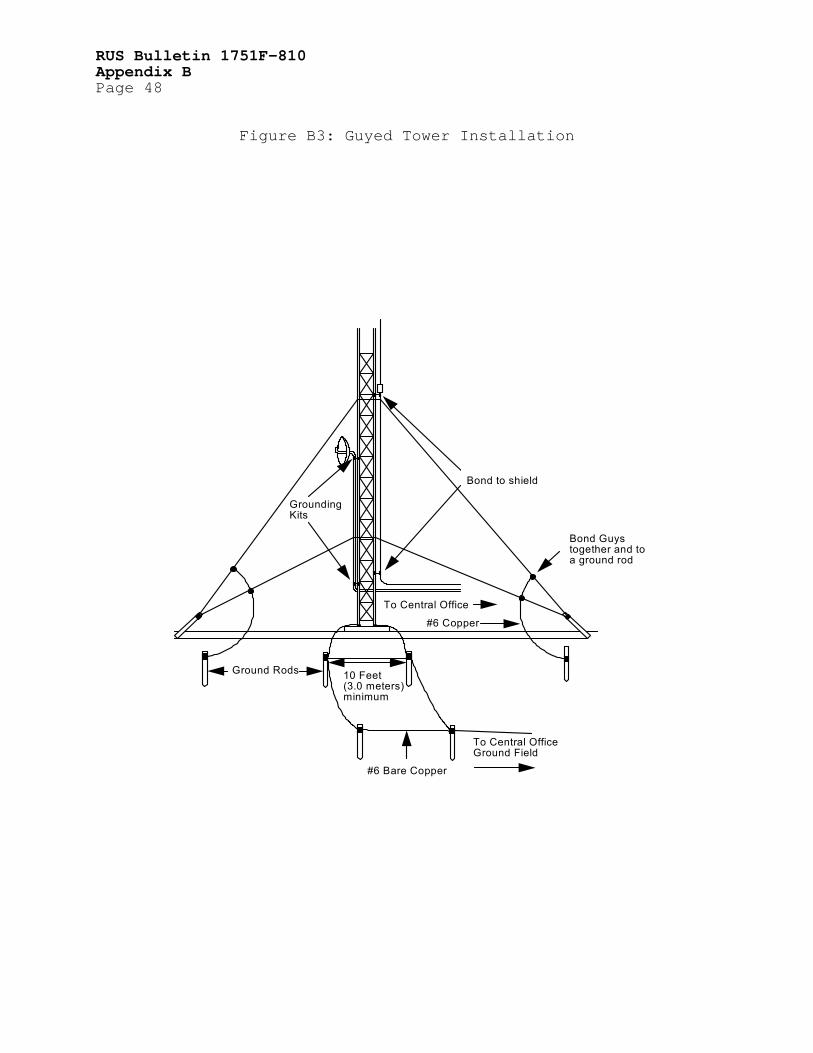
RUS Bulletin 1751F-810 Appendix B Page 48
Figure B3: Guyed Tower Installation
10 Feet(3.0 meters)minimum
#6 Bare Copper
To Central OfficeGround Field
Ground Rods
Bond to shield
GroundingKits
To Central Office
Bond Guystogether and toa ground rod
#6 Copper

RUS Bulletin 1751F-810 Appendix B
Page 49
Figure B4: Pole Mounted Installation
To Central Office
Grounding Kit
Grounding Kit
To Central Ground Field
#6 Bare Copper
Ground Rods
10 foot(3.0 meter)minimum
2 foot (0.6 meter) minimum below grade

RUS Bulletin 1751F-810 Appendix B Page 50
Figure B5: Building Mounted Installation
#6 Copper
Grounding Kits
To Central OfficeGround Field
#2 Copper
Ground Rod#6 Bare Copper2 foot (0.6 meter)minimum below grade

RUS Bulletin 1751F-810 Appendix B
Page 51
Figure B6: Tower Ground Kit Installation
Tower leg
Transmission line
Ground kits should always runin a downward direction towardground.

RUS Bulletin 1751F-810 Appendix B Page 52
Figure B7: Entrance Grounding at Central Office
Entry Plane
Manufacturer's entry boot
Transmission Line
#6 Copper
To Central OfficeGround Field
Connection to ground fieldshould be external tothe Central Office building
Grounding kits should connect tothe entry plate at a common pointand run in a downward directiontoward ground.

RUS Bulletin 1751F-810 Appendix B
Page 53
This page has been intentionally left blank.

RUS Bulletin 1751F-810 Appendix C Page 54
APPENDIX C
ANALYSIS OF CENTRAL OFFICE GROUNDING SYSTEMS C1. GENERAL C1.1 Evaluating a Central Office Grounding System: This Appendix discusses a technique for analyzing a central office grounding system. The method presented will provide information as to where there may be missing elements in a grounding system. Use of this technique is recommended for analyzing newly installed grounding systems. Further, annual analysis of all grounding systems is recommended so that any problems which may have arisen during the year may be detected and corrected. C1.2 Ammeter for Grounding System Analysis: The procedure uses a small clamp-on probe together with a portable ammeter. The ammeter should have a useful range from milliamperes to at least twenty amperes. There are several types available which are capable of completing these tests. C2. PROCEDURE C2.1 Start of Procedure: Start the analysis at the Master Ground Bar (MGB). This is the hub of the central office grounding system (the single point ground). C2.1.1 First, prepare a sketch of the MGB with all of the conductors, labeling each with the name of the ground bar to which it is connected at its other end. C2.1.2 Second, place the clamp or probe around each conductor and read the ac current. Then, record the current at the appropriate conductor on the sketch. Repeat until the current associated with each conductor has been recorded on the sketch. The completed sketch at this location will be similar to the one shown in Figure C1: Master Ground Bar Currents. C2.2 Cable Entrance Ground Bar: Proceed next to the Cable Entrance Ground Bar (CEGB) and prepare a sketch similar to the one prepared for the MGB. Then complete the measuring and recording of the conductor currents in the same manner as with the MGB. A sample CEGB sketch is shown in Figure C2: CEGB Currents. C2.3 Other Ground Bars: Complete the same operations for all of the remaining ground bars in the office: MDF Ground Bar (MDFB), Ground Window Bar (GWB), and any Intermediate Ground Bars (IGB).

RUS Bulletin 1751F-810 Appendix C
Page 55
C2.4 Checking the Conductors: During preparation of the sketches at each location, check to determine if all of the conductors are connected to the ground bar in accordance with the guidelines of this bulletin. The most critical conductors are those to the Surge Producers (interior radio equipment, cable shields, and cable pairs), and the Surge Absorbers (power neutral, Central Office ground field, and water system). C3. ANALYSIS OF THE CONDUCTOR CURRENTS C3.1 Predicting Current Levels: Prediction of the precise current level that will be flowing along each grounding conductor is not possible. These levels are determined by the amount of voltage induced in the outside telecommunications facilities from paralleling power systems. Therefore, only a comparative analysis of the recorded current values can be made. Table C-1 lists the typical range of currents for various grounding conductors. C3.2 Current Levels of Conductors Connected to Surge Absorbers: The most important factor in the analysis is the comparison of current levels on conductors connected to the Surge Absorbers (power neutral, water system, and Central Office ground field). The maximum current should be flowing on the ac bypass conductor (the conductor between the MGB and the neutral ground bar in the power system entrance panel.) Where there is a metallic water system, the next highest current should be flowing in the conductor between the MGB and the water system. There should be less current flowing on the conductor to the central office ground field than on the other two conductors. C3.2.1 Systems installed in areas where there are no metallic water systems that can be integrated into the system should have the maximum current flowing to the power system neutral via the ac bypass conductor. The current flowing to the central office ground field should be smaller than that flowing to the power system neutral as it would be in systems where all three Surge Absorbers are present. C3.2.2 Some systems will be installed in areas where not only are there no metallic water systems but, sometimes the power systems are operating with either unigrounded neutrals or in a delta configuration. In these areas, the only ground available for the central office will be the central office ground field. The level of induced power influence in these areas will normally be quite low and the measured current to the ground field will usually be in the same range as that found at all offices. C3.3 Current Flowing to Power System Neutral: The range of current that will be typically found flowing to the power system neutral will be in the range of one to twenty amperes. The

RUS Bulletin 1751F-810 Appendix C Page 56 actual level will fluctuate within this range depending on the level of power influence. C3.3.1 Current flowing toward the water system will be lower than that flowing in the ac bypass conductor. There are several factors that control the level of current in the conductor to the water system. The major factor is how extensive the metallic water system is. When the metallic portion of the system is only ten to fifteen feet (3 to 4.6 meters) in length, the current will typically be in the range of 100 to 1000 milliamperes in offices that are served by power systems that do not have a grounded neutral. Currents in this range found in offices served by grounded-neutral power systems usually indicate that one of two grounding conductors are missing or open circuited. Either the ac bypass conductor or the conductor between the water system and the neutral ground bar in the power entrance panel (required by the National Electrical Code) is missing or open circuited. This should be corrected before proceeding further. When the office is served by a grounded neutral power system or when the metallic water system covers an extensive area, the current in the conductor to the water system will be in the range of one to five amperes or more. C3.3.2 The current measured on the conductor to the central office ground field will be significantly lower than that flowing to the other Surge Absorbers in all cases. This current will typically be in the range of 100 to 500 milliamperes. C3.4 The ac Current from Power System Induction in the Outside Plant Flowing into the Central Office on the cable shields will be in the range of one to twenty amperes. This is controlled by the level of power influence and will fluctuate over a wide range during the day as power system load demand changes. This current will be measured on the conductor between the CEGB and the MGB. Where the conductor from the central office ground field enters the office in the cable vault and is connected to the CEGB, the total current to the MGB will be less than current that flows directly to the ground field from the cable shields. Because of the normal current fluctuations, the currents assumed to be flowing toward and away from each ground bar will not always add precisely. Differences as high as fifteen percent are normal. When the difference is higher than this, remeasure the currents. C3.4.1 The induced current flowing into the office on the cable pairs will normally flow to ground via the battery feeds on the line cards. This current returns to the MGB via the conductor to the positive battery terminal. Its magnitude is typically in the range of 100 to 500 milliamperes. Should a significantly higher current be measured, the ac bypass conductor is usually missing or open-circuited. Some offices have line circuits with a high impedance to ground (10,000 ohms and over). The current between

RUS Bulletin 1751F-810 Appendix C
Page 57
the positive battery terminal and the MGB in these offices will be negligible. C3.4.2 Some central offices are collocated with CATV systems. A significant current will flow into the offices on the outer shields of the coaxial cable associated with these systems. These cable shields should be integrated into the central office grounding system via the CEGB. The current from CATV systems can exceed that which is associated with the outside plant of the telecommunications system. This current will typically range from one to twenty, or more, amperes. C3.5 Current on Other Grounding Conductors: The range of current measured on all other grounding conductors associated with the grounding system will vary from a trace to several hundred milliamperes. These currents are normal and relate to how closely the equipment in the bays is associated with the outside plant. C3.6 Current on Conductor to the Ground Window Bar: There will always be some current measured on the conductor to the Ground Window Bar (GWB). This current will usually be in the range of 50 to 200 milliamperes. When, a higher current is found, the search should proceed beyond the GWB to determine why the higher current is present and whether such current is detrimental to the specific equipment installed in the office. C4. VISUAL INSPECTION C4.1 General: A visual inspection should be completed during measuring. Each grounding conductor should be traced from the ground bar to its far end. There are several items which should be closely checked during this stage of the operation. These are outlined in the following paragraphs: C4.1.1 Conductor: The conductor should be continuous, end to end, with no splices, or intermediate terminations. Also, the conductor should be sized for the distance between the two ends, as shown in Figure 7 of this bulletin. C4.1.2 Sharp Bends: There should be no sharp bends along the entire length of the conductor. Sharp bends increase the surge impedance of the conductor reducing the grounding system efficiency. C4.1.3 Grounding Conductors should not pass through any metallic conduit or pipe as this will also increase the surge impedance of the grounding conductor. Should an existing grounding conductor be found passing through a metallic pipe, solidly strap it to the pipe at each end. This will eliminate the adverse condition and provide a low impedance path for surge currents.

RUS Bulletin 1751F-810 Appendix C Page 58 C4.1.4 Copper Ground Bars in the grounding system should be mounted on insulators except for the MDFB and as noted in paragraph 7.3.4.1.2. The MDFB may be mounted directly on the metal frame. The protector strips on the MDF should be connected together with #6 solid copper wire, rather than relying on the steel frame to conduct surge currents to ground. C4.2 The Area outside the Building should also be inspected to determine that the entire grounding system has been properly integrated. The following paragraphs list those items which should be studied during the outside inspection: C4.2.1 Where a fence exists near or adjacent to a central office or similar type telecommunications facility, the following grounding provisions of a chain link post, chain link fence and, where equipped, fence barbed wire should be installed at each corner fence post, at least one fence post between corner fence posts and at each post supporting a gate, supporting a gate latch unit or a security provision providing a movable fence opening: At a point within 6 inches (15 centimeters) laterally away from a fence post or the vertical projection of the fence post, install a 6 AWG solid bare copper grounding conductor by: C4.2.1.1 Bonding one end of the conductor to the upper most strand of barbed wire, if barbed wire is not installed go to C4.2.1.3; C4.2.1.2 Interweaving the other conductor end vertically down through the remaining lower strands of barbed wire; C4.2.1.3 Bonding the conductor to the upper most horizontal rail of the chain link fence at the point on the conductor where the conductor is adjacent to the upper most fence rail when the conductor is pulled down tightly; C4.2.1.4 Interweaving the free conductor end down through the chain link fence mesh; C4.2.1.5 Bonding the conductor to the lower most fence rail of the fence at the point on the conductor where the conductor is adjacent to the upper most fence rail when the conductor is pulled down tightly; C4.2.1.6 Bonding the conductor end to an 8 foot (2.4 meters) ground rod driven into the soil approximately two feet (60 centimeters) horizontally away from the plane of the chain link fence, vertically in line with the conductor feed, and on the outside of the fence. The top of the ground rod should be one foot (30.5 centimeters below the soil surface; and

RUS Bulletin 1751F-810 Appendix C
Page 59
C4.2.1.7 Bonding at least one of the installed fence ground rods to the central office or remote access node ground field with at least a 6 AWG bare copper wire. Bonding to the ground field should be completed somewhere outside of the building, preferably in a handhold. C4.2.1.8 The bonding and grounding described in C4.2.1.1 through C4.2.1.7 should be bare copper bonding jumper. All wire to metallic post or ground rod bonding should include the options of brazing, welding, mechanical and high compression connections, and ground clamps listed for the purpose by a testing laboratory acceptable to the authority having jurisdiction. (Reference UL#96 and IEEE 837 documents.) Any tower within a fenced area shall be grounded as noted in C4.2.2. C4.2.2 Radio towers located adjacent to the central office building should have a dedicated ground field as if they were located in an isolated area (Refer to Appendix B). This ground field should be bonded to the central office ground field outside of the building. C4.2.3 Air conditioning or heating systems that are mounted on platforms, outside and adjacent to the building should also be provided with a separate dedicated ground field. This ground field should be bonded to the central office ground field outside of the building. Further, air ducts from the system that enter the building should have fiber insulating sections in them just before they enter the building. The internal duct systems should be bonded into the building steel. C4.2.4 Connections to the central office ground field, outside of the building, should be mounted in hand holes or ground wells. Refer to Bulletin 1751F-802. C5. COMMON PROBLEMS C5.1 Introduction: Several common problems listed below have been found during visual inspections of central office grounding systems. They are included in this Appendix to alert the person reviewing the grounding system to some specific items of importance. C5.2 Routing of Surge Producers and Surge Absorbers: The routing of surge-carrying grounding conductors (Surge Producers and Surge Absorbers) in cable racks and troughs parallel to signal carrying-conductors that enter the isolated zone is a rather frequently observed condition that can result in line circuit damage during periods of surge activity. Since the signaling conductors in this area are not shielded, the coupling is from the E, the voltage field, rather than the H, the magnetic field. The location of the signaling conductors is on the

RUS Bulletin 1751F-810 Appendix C Page 60 central office side of the main frame protectors and thus they are extremely vulnerable to surge damage. C5.3 Conductor Size should not change at the end of a grounding conductor routing. This will reduce the efficiency of the grounding conductor's ability to carry surge currents to ground. This condition is most frequently found in the ac bypass conductor near the point where the conductor enters the power system entrance panel, as illustrated in Figure C3: Undesirable Reduction in Size of Grounding Conductor. The ac bypass conductor should be continuous from end to end with no change in conduit or size. C5.4 Butt Splices: At some locations not only has the conductor size been reduced but an unacceptable splice is used, as shown in Figure C4: Undesirable Butt-Splice in Grounding Conductor. Surge currents will not follow a sharp turn, which presents a very high impedance to fast rising surge currents. Instead, the surge currents will seek and find another path to ground. This is likely to result in damage to the sensitive electronic equipment. Therefore, butt splices should never be used in grounding connections. C5.5 Routing the ac Bypass Conductor to a Branch Power Panel: Sometimes, the ac bypass conductor is found routed to a branch power panel rather than back to the power entrance panel. This condition can also lead to some unexpected problems. First, the size of the conductor between the branch and entrance panels is apt to be smaller than the recommended size. Second, the conductor between the two panels will be located in metallic conduit and the conductor and conduit will not be solidly bonded at each end. This will cause a high voltage differential to be present during periods of surge current. Last, the conductor between the two panels will be carrying load current from electrical service beyond the branch panel. Part of this current is likely to flow back through the MGB. Transients which can be transmitted into the switching equipment can result in damage to electronic components. These transients are caused by switching in the power loads. The ac bypass conductor should be routed in the prescribed manner for maximum protection of the switching equipment. C5.6 The protector strips at the MDF should be bonded together with a #6 solid copper conductor but inspection may find that the string of strips has not been bonded to the MDFB. This arrangement produces a high impedance to surge currents and will force the surge into the line circuit. C5.7 Secondary Power Protection: Many offices are found lacking secondary power protection. Secondary power protection is a very important aspect of Central Office protection. There is justification for using such protection regardless of the

RUS Bulletin 1751F-810 Appendix C
Page 61
lightning activity of the area since even in areas of moderate to light activity there will be an occasional thunderstorm and power system transients (switching, etc.) take place in all areas. The cost of the secondary protection is small compared to the cost of repairing damage.
TABLE C-1 TYPICAL GROUNDING CONDUCTOR CURRENT RANGES A. Office with CO ground field, MGN and metallic water system. B. Office with CO ground field and MGN. C. Office with CO ground field and metallic water system (delta or unigrounded wye connected power) D. Office with CO ground field (delta or unigrounded wye power system) Office Type: A B C D________ Conductor Between MGB and ... Power Entrance Panel Board 1-20A 1-20A 10-500mA 10-500mA Water System 1-5A 1-5A .1-1A CO Ground Field 100-500mA 100-500mA 100-500mA 100-500mA CEGB 1-20A 1-20A .2-1A 100-800mA Positive Battery 100-500mA 100-500mA 10-200mA 10-200mA GWB 0-100mA 0-100mA 0-100mA 0-100mA MDFB 100-300mA 100-300mA 50-100mA 50-100mA CXR, or other Equipment Bays 100-300mA 100-300mA 50-100mA 50-100mA C5.8 The Conductor from the Central Office Ground Field Connected to the CEGB: Sometimes, the conductor from the central office ground field is brought into the cable vault and connected to the CEGB. This configuration can be used where the conductor installed between the CEGB and the MGB is large enough to make one bar an extension of the other. This is accomplished when the conductor is at least 750 MCM. Smaller conductors may cause problems and should not be used. C5.9 Dividing the MGB into Two Bars: Some offices have an arrangement where the MGB is divided into two bars. The Surge Absorbers and Surge Producers are all connected to one bar and all other grounding conductors are connected to the other. The conductor between these two ground bars is sometimes undersized. This arrangement is acceptable if the conductor is large enough to make one bar an extension of the other. Installation of a 4/0, or larger, conductor is recommended. C5.10 Avoiding Bends: The bends placed in the conductors to improve the appearance increase the impedance to flow of surge currents and reduce the efficiency of the overall grounding system. The conductors should be connected to the ground bars and routed in the most direct manner possible with, ideally, no bends in the conductors. Where bends are necessary, they should

RUS Bulletin 1751F-810 Appendix C Page 62 be gentle so as to add minimum impedance to the flow of surge currents.

RUS Bulletin 1751F-810 Appendix C
Page 63
Figure C1: Master Grounding Bar Currents
3.5 A 250 mA 180 mA 100 mA
GWBCXR & RPTR BaysAC Bypass
3.2 A
300 mA
800 mA
300 mA 500 mA
CEGB MDFB Water Pipe
Central OfficeGround Field
+Battery

RUS Bulletin 1751F-810 Appendix C Page 64
Figure C2: CEGB Currents
4 A 350 mA
2.5 A 1.8 A
MGB
COGroundField
CableShields

RUS Bulletin 1751F-810 Appendix C
Page 65
Figure C3: Undesirable Size Reduction in Grounding Conductor
#6
#2/0
RUS Bulletin 1751F-810 Appendix C Page 66
Figure C4: Undesirable Butt-Splice
#6#2/0